

Page 1
TI00508C/07/EN/02.18
71397653
Products
Solutions Services
Technical Information
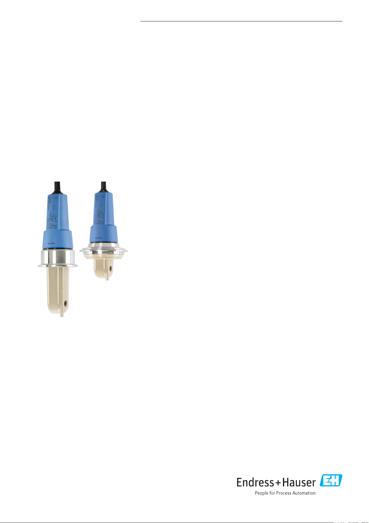
Indumax CLS54D
Hygienic inductive conductivity sensor for
applications in the food, beverage, pharmaceutical
and biotech industries
Application
The CLS54D conductivity sensor is specifically designed for use in hygienic
applications in the food, beverage and pharmaceutical industries and in
biotechnology. Thanks to its hygiene certificates and its food-safe, virgin PEEK
design without any joints or crevices, it meets the strict demands of these industries.
The CLS54 is ideal for:
• Phase separation of product/water and product/product mixtures in pipe systems
• Control of cleaning in place (CIP) processes in the return line
• Concentration control in the remaking of CIP cleaning agents
• Product monitoring in pipes, bottling plants and quality assurance
• Leakage monitoring
in the following industries:
• Dairies
• Breweries
• Beverages (water, juices, soft drinks)
• Pharmaceuticals and biotechnology
Use with Liquiline CM42, CM44x and CM14 transmitters.
Your benefits
• Unique hygienic design, therefore no risk of recontamination
• Has all the process connections commonly used in the hygiene sector
• Fast measurement with temperature response time t90 under 26 s, ensuring safe
and efficient phase separation
Other advantages of Memosens technology
• Maximum process safety
• Data security thanks to digital data transmission
• Very easy to use as sensor data saved in the sensor
• Recording of sensor load data in the sensor enables predictive maintenance
Page 2
Function and system design
1 2
3
4
5
1
3
2
Indumax CLS54D
Measuring principle
Measuring system
Inductive conductivity measurement
An oscillator (1) generates an alternating magnetic field in the primary coil (5), which induces a
current flow (4) in the medium. The strength of the current depends on the conductivity and thus on
the ion concentration in the medium. The current flow in the medium, in turn, generates a magnetic
field in the secondary coil (3). The resulting induced current is measured by the receiver (2) and used
to determine the conductivity.
1
Oscillator
2
Receiver
3
Secondary coil
4
Current flow in the medium
5
Primary coil
Advantages of inductive conductivity measurement:
• No electrodes and therefore no polarization effects
• Accurate measurement in media with a high degree of
pollution and a tendency to form buildup
• Complete galvanic isolation of the measurement and the
medium
A0024926
A complete measuring system consists of the following components at least:
• The CLS54D inductive conductivity sensor
• A transmitter, e.g. Liquiline CM44x
1 Example of a measuring system
1 Transmitter Liquiline CM44x
2 Indumax CLS54D
3 Measuring cable
2 Endress+Hauser
A0035902
Page 3

Indumax CLS54D
Communication and data processing
Communication with the transmitter
Always connect digital sensors with Memosens technology to a transmitter with Memosens
technology. Data transmission to a transmitter for analog sensors is not possible.
Digital sensors can store measuring system data in the sensor. These include the following:
• Manufacturer data
– Serial number
– Order code
– Date of manufacture
• Calibration data
– Calibration date
– Cell constant
– Delta cell constant
– Number of calibrations
– Serial number of the transmitter used to perform the last calibration
• Operating data
– Temperature application range
– Conductivity application range
– Date of initial commissioning
– Maximum temperature value
– Hours of operation at high temperatures
Reliability
Maintainability
Integrity
Dependability
Memosens technology digitizes the measured values in the sensor and transmits the data to the
transmitter via a . The result:
• Automatic error message if sensor fails or connection between sensor and transmitter is
interrupted
• Immediate error detection increases measuring point availability
Easy handling
Sensors with Memosens technology have integrated electronics that store calibration data and other
information (such as total hours of operation and operating hours under extreme measuring
conditions). Once the sensor has been connected, the sensor data are transferred automatically to
the transmitter and used to calculate the current measured value. As the calibration data are stored
in the sensor, the sensor can be calibrated and adjusted independently of the measuring point. The
result:
• Easy calibration in the measuring lab under optimum external conditions increases the quality of
the calibration.
• Pre-calibrated sensors can be replaced quickly and easily, resulting in a dramatic increase in the
availability of the measuring point .
• Maintenance intervals can be defined based on all stored sensor load and calibration data and
predictive maintenance is possible.
• The sensor history can be documented on external data carriers and in evaluation programs. Thus,
the current application of the sensors can be made to depend on their previous history.
• Measured values cannot be distorted by moisture.
• EMC safety provided by screening measures in digital measured value transmission.
Input
Measured values
Endress+Hauser 3
• Conductivity
• Temperature
Page 4
Indumax CLS54D
2
A
B
20 (0.79)
20 (0.79)
PK
85
GY
86
BN
87
WH
88
GN
97
YE
98
63 (2.48)
75 (2.95)
80 (3.15)
1
Measuring ranges
Cell constant
Temperature measurement
Electrical connection
Conductivity Recommended range: 100 μS/cm to 2000 mS/cm
(uncompensated)
Temperature –10 to +150 °C (+14 to +302 °F)
k = 6.3 cm
–1
Pt1000 (Class A according to IEC 60751)
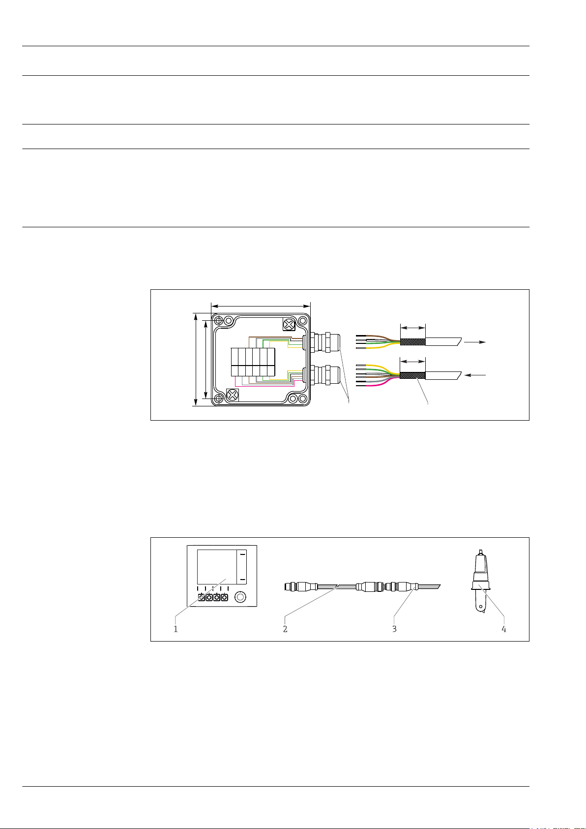
Power supply
The sensor is supplied with a fixed cable. The wiring diagram is provided in the Operating
Instructions of the transmitter used.
Connection via a junction box is necessary for a cable connection. The extension to the transmitter is
via the CYK11 cable.
A0032587
2 Connection with CYK11 cable extension via junction box, dimensions in mm (inch)
1 Cable glands - shield fixed in gland
2 Shielding
A CYK11 from transmitter
B Sensor cable
Sensors with a fixed cable and M12 plug can be extended with the CYK11 measuring cable and an
M12 socket.
A0017842
3 CYK11 for extension with M12 connection
1 Transmitter
2 CYK11 measuring cable with M12 connection
A CLS54D connecting cable with M12 plug
B Sensor CLS54D
4 Endress+Hauser
Page 5

Indumax CLS54D
> 1 m (3.3 ft)
Performance characteristics
Conductivity response time
Temperature response time
Maximum measured error
Repeatability
Orientation
t95 ≤ 2 s
t90 ≤ 26 s
< 100 °C (212 °F): ±(10 μS/cm + 0.5 % of reading), after calibration
> 100 °C (212 °F): ±(25 μS/cm + 0.5 % of reading), after calibration
0.2 % of reading + 3 µS/cm
Installation
The sensor must be completely immersed in the medium. Avoid air bubbles in the area of the sensor.
A0017691
4 Installation positions of the conductivity sensor
If the flow direction changes (after pipe bends), turbulence in the medium can result. Install the
sensor at a distance of at least 1 m (3.3 ft) downstream from a pipe bend.
The product should flow along the hole of the sensor (see the arrows on the housing). The
symmetrical measuring channel allows flow in both directions.
Endress+Hauser 5
Page 6

Indumax CLS54D
a
1
2
a [inch]
0
5
10 15
20
2525
a [mm]
0 80.
1 00.
1 20.
1 40.
f
0.20
0.39
0.59
0.79
0.98
Installation factor
The ionic current in the liquid is affected by the walls in confined
installation conditions. This effect is compensated by what is
referred to as the installation factor. The installation factor can be
entered in the transmitter for the measurement or the cell constant
is corrected by multiplying by the installation factor.
The value of the installation factor depends on the diameter and
the conductivity of the pipe nozzle as well as the distance a
between the sensor and the wall.
The installation factor f (f = 1.00) can be disregarded if the
distance to the wall is sufficient (a > 15 mm, from DN 65).
If the distance to the wall is smaller, the installation factor
increases for electrically insulating pipes (f > 1), and decreases for
electrically conductive pipes (f < 1).
It can be measured using calibration solutions, or a close
approximation can be determined from the diagram below.
A0032681
5 Installation CLS54D
a Wall distance
Air set
Ambient temperature range
Storage temperature
Humidity
Degree of protection
A0034874
6 Relationship between installation factor f and wall distance a
1 Electrically conductive pipe wall
2 Electrically insulating pipe wall
The digital sensor has already been adjusted at the factory. Onsite compensation is not required.
Environment
-20 to +60 °C (-4 to 140 °F)
-25 to +80 °C (-13 to +176 °F)
5 to 95 %
IP 68 / NEMA type 6P (1 m water column, 25 °C, 168 h)
6 Endress+Hauser
Page 7

Indumax CLS54D
A
50 70
1 01 1 05
10 30
125
90
0
–10
[° C]
9
13
[bar]
32
50
86
122
158
230
302194
257
[°F]
130.5
188.5
[psi]
6
B
1
87
14.5
p (abs.)
Process
Process temperature
Sterilization
Process pressure (absolute)
Temperature/pressure ratings
-10 to +125 °C (+14 to +257 °F)
150 °C (302 °F) / 6 bar (87 psi) absolute, (max. 60 min.)
13 bar (188.5 psi) up to 90 °C (194 °F)
9 bar (130.5 psi) at 125 °C (257 °F)
Underpressure down to 0.1 bar (1.45 psi)
Flow velocity
A0008379
7 Pressure/temperature ratings
A Temporarily for sterilization (max. 60 min.)
B MAWP (maximum allowable working pressure) according to ASME-BPVC Sec. VIII, Div 1 UG101 for CRN
registration
For low-viscosity media:
Max. 10 m/s (32.8 ft/s) For pipe diameters ≥ 80 mm (3.15 in)
Max. 5 m/s (16.4 ft/s) For pipe diameters ≥ 50 < 80 mm (≥ 1.97 < 3.15 in)
Endress+Hauser 7
Page 8

Design
1
2
3
4
Ø 6 (0.24)
11.5 (0.45)
132.5 (5.22)
58 (2.28)
78.5 (3.09)
Ø 8.9 (0.35)
10.2 (0.4)
36.5
(1.44)
16 (0.63)
A
B
Indumax CLS54D
Mechanical construction
A0035912
8 Indumax CLS54D
1 Housing
2 Temperature sensor
3 Flow opening
4 Process connection
Dimensions
Weight
9 Dimensions in mm (in)
A Long version
B Short version
0.3 to 0.5 kg (0.66 to 1.1 lb.) depending on version plus cable
A0035913
8 Endress+Hauser
Page 9

Indumax CLS54D
A 5A
M 5V
SMS C 1S
B 5C
V 4A
Materials
Surface roughness
Process connections
In contact with medium Virgin PEEK
Not in contact with medium PPS-GF40
SMS coupling: stainless steel 1.4301 (AISI 304) or
1.4307 (AISI 304L)
Sanitary coupling: stainless steel 1.4404 (AISI 316L)
Cable gland: PEEK
Seals: FKM,
Cable: TPE
Ra ≤ 0.8 μm (smooth, injection-molded PEEK surface) at surfaces in contact with medium
Chemical resistance
AA5 Aseptic coupling DIN 11864-1 form A, for pipe according to DIN 11850, DN 50 (the sensor has
the shape of the aseptic liner)
MV5 Sanitary connection DIN 11851, DN 50
SMS SMS coupling 2"
CS1 Clamp ISO 2852 (also for TriClamp, DIN 32676), 2" (long design)
BC5 NEUMO BioControl D50, for pipe connection DN 40 (DIN 11866 series A, DIN 11850), DN 42.4
(DIN 11866 series B, DIN EN ISO 1127) or 2" (DIN 11866 series C, ASME-BPE)
VA4 Varivent N DN 40 to 125
1) The sanitary connection DIN 11851 is generally not considered to be hygienic. With the SKS Siersma
adapter, this process connection meets the requirements of the 3-A standard.
2) Does not meet the hygienic requirements of EHEDG.
3) Only hygienic in conjunction with Hyjoin PEEK/stainless steel ring made by Hyjoin Ltd., UK, and KALREZ
seal by Dupont
2)
1)
3)
Medium Concentration PEEK
Caustic soda NaOH 0 to 15 % 20 to 90 °C (68 to 194 °F)
Nitric acid HNO
3
0 to 10 % 20 to 90 °C (68 to 194 °F)
Endress+Hauser 9
A0035914
Page 10

Medium Concentration PEEK
Phosphoric acid H3PO
Sulfuric acid H2SO
Peracetic acid H3C-CO-OOH 0.2 % 20 °C (68 °F)
4
4
0 to 15 % 20 to 80 °C (68 to 176 °F)
0 to 30 % 20 °C (68 °F)
Certificates and approvals
Indumax CLS54D
mark
Declaration of Conformity
The product meets the requirements of the harmonized European standards. As such, it complies
with the legal specifications of the EU directives. The manufacturer confirms successful testing of the
product by affixing to it the mark.
Hygiene FDA
All materials in contact with the product are listed by the FDA.
3-A
Certified according to 3-A Standard 74- ("3-A Sanitary Standards for Sensor and Sensor Fittings and
Connections Used on Milk and Milk Products Equipment").
Biological reactivity (USP class VI) (optional)
Biological reactivity test certificate (Certificate of Compliance) according to USP (United States
Pharmacopoeia) part<87> and part <88> class VI with lot number traceability of materials in contact
with the medium.
10 Endress+Hauser
Page 11

Indumax CLS54D
Ordering information
Product page
Product Configurator
Scope of delivery
www.endress.com/cls54D
On the product page there is a Configure button to the right of the product image.
1. Click this button.
The Configurator opens in a separate window.
2. Select all the options to configure the device in line with your requirements.
In this way, you receive a valid and complete order code for the device.
3. Export the order code as a PDF or Excel file. To do so, click the appropriate button on the right
above the selection window.
For many products you also have the option of downloading CAD or 2D drawings of the
selected product version. Click the CAD tab for this and select the desired file type using
picklists.
The scope of delivery includes:
• Sensor in the version ordered
• Operating Instructions
Accessories
The following are the most important accessories available at the time this documentation was
issued.
For accessories not listed here, please contact your Service or Sales Center.
‣
Cable extension
Calibration solutions
Memosens data cable CYK11
• Extension cable for digital sensors with Memosens protocol
• Product Configurator on the product page: www.endress.com/cyk11
Technical Information TI00118C
Conductivity calibration solutions CLY11
Precision solutions referenced to SRM (Standard Reference Material) by NIST for qualified
calibration of conductivity measuring systems in accordance with ISO 9000
• CLY11-B, 149.6 μS/cm (reference temperature 25 °C (77 °F)), 500 ml (16.9 fl.oz)
Order No. 50081903
• CLY11-C, 1.406 mS/cm (reference temperature 25 °C (77 °F)), 500 ml (16.9 fl.oz)
Order No. 50081904
• CLY11-D, 12.64 mS/cm (reference temperature 25 °C (77 °F)), 500 ml (16.9 fl.oz)
Order No. 50081905
• CLY11-E, 107.00 mS/cm (reference temperature 25 °C (77 °F)), 500 ml (16.9 fl.oz)
Order No. 50081906
Technical Information TI00162C
Endress+Hauser 11
Page 12

www.addresses.endress.com
 Loading...