

Page 1
BA01149C/07/EN/07.19
71454911
2019-10-31
Products Solutions Services
Operating Instructions
Smartec CLD18
Conductivity measuring system
Page 2

Page 3

Smartec CLD18 Table of contents
Table of contents
1 About this document ........... 4
1.1 Warnings ........................... 4
1.2 Symbols used ........................ 4
1.3 Symbols on device .................... 5
2 Basic safety instructions ....... 5
2.1 Requirements for personnel ........... 5
2.2 Designated use ...................... 5
2.3 Workplace safety .................... 5
2.4 Operational safety ................... 7
2.5 Product safety ....................... 7
2.6 IT security .......................... 7
3 Product description ............. 8
3.1 Product design ....................... 8
4 Incoming acceptance and
product identification .......... 9
4.1 Incoming acceptance ................. 9
4.2 Product identification ................. 9
4.3 Scope of delivery .................... 10
4.4 Certificates and approvals ............ 11
5 Installation .................... 11
5.1 Installation conditions ............... 11
5.2 Mounting the compact device ......... 17
5.3 Post-installation check ............... 17
9 Diagnostics and
troubleshooting ............... 34
9.1 General troubleshooting ............. 34
9.2 Troubleshooting instructions ......... 34
9.3 Queued diagnostic messages .......... 35
10 Maintenance .................. 38
10.1 Maintenance tasks .................. 38
11 Repair .......................... 39
11.1 General notes ...................... 39
11.2 Return ............................ 39
11.3 Disposal ........................... 39
12 Accessories .................... 40
12.1 Calibration solutions ................ 40
13 Technical data ................. 40
13.1 Input .............................. 40
13.2 Output ............................ 41
13.3 Power supply ....................... 41
13.4 Performance characteristics .......... 42
13.5 Environment ....................... 42
13.6 Process ............................ 43
13.7 Mechanical construction ............. 44
Index ................................. 48
6 Electrical connection .......... 17
6.1 Connecting the transmitter ........... 17
6.2 Ensuring the degree of protection ..... 21
6.3 Post-connection check ............... 21
7 Operation options ............. 22
7.1 Overview of operating options ........ 23
7.2 Structure and function of the operating
menu ............................. 24
8 Commissioning ................ 25
8.1 Switching on the measuring device .... 25
8.2 Display settings (Display menu) ....... 25
8.3 Configuring the measuring device ..... 26
8.4 Advanced settings .................. 26
8.5 Calibration (Calibration menu) ........ 31
Endress+Hauser 3
Page 4
About this document Smartec CLD18
1 About this document
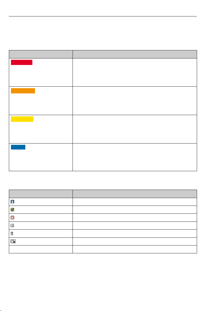
1.1 Warnings
Structure of information Meaning
DANGER
L
Causes (/consequences)
If necessary, Consequences of noncompliance (if applicable)
Corrective action
‣
WARNING
L
Causes (/consequences)
If necessary, Consequences of noncompliance (if applicable)
Corrective action
‣
CAUTION
L
Causes (/consequences)
If necessary, Consequences of noncompliance (if applicable)
Corrective action
‣
NOTICE
Cause/situation
If necessary, Consequences of noncompliance (if applicable)
Action/note
‣
This symbol alerts you to a dangerous situation.
Failure to avoid the dangerous situation will result in a fatal or serious injury.
This symbol alerts you to a dangerous situation.
Failure to avoid the dangerous situation can result in a fatal or serious injury.
This symbol alerts you to a dangerous situation.
Failure to avoid this situation can result in minor or more serious injuries.
This symbol alerts you to situations which may result in damage to property.
1.2 Symbols used
Symbol Meaning
Additional information, tips
Permitted or recommended
Not permitted or not recommended
Reference to device documentation
Reference to page
Reference to graphic
Result of a step
4 Endress+Hauser
Page 5
Smartec CLD18 Basic safety instructions
1.3 Symbols on device
Symbol Meaning
Reference to device documentation
2 Basic safety instructions
2.1 Requirements for personnel
• Installation, commissioning, operation and maintenance of the measuring system may be
carried out only by specially trained technical personnel.
• The technical personnel must be authorized by the plant operator to carry out the specified
activities.
• The electrical connection may be performed only by an electrical technician.
• The technical personnel must have read and understood these Operating Instructions and
must follow the instructions contained therein.
• Faults at the measuring point may only be rectified by authorized and specially trained
personnel.
Repairs not described in the Operating Instructions provided must be carried out only
directly at the manufacturer's site or by the service organization.
2.2 Designated use
The compact measuring system is used for inductive conductivity measurement in liquids with
medium to high conductivity.
Use of the device for any purpose other than that described, poses a threat to the safety of
people and of the entire measuring system and is therefore not permitted.
The manufacturer is not liable for damage caused by improper or non-designated use.
NOTICE
Applications outside specifications!
Incorrect measurements, malfunctions and even measuring point failure could result
Use the product only in accordance with the specifications.
‣
Pay attention to the technical data on the nameplate.
‣
2.3 Workplace safety
As the user, you are responsible for complying with the following safety conditions:
• Installation guidelines
• Local standards and regulations
Endress+Hauser 5
Page 6

Basic safety instructions Smartec CLD18
Electromagnetic compatibility
• The product has been tested for electromagnetic compatibility in accordance with the
applicable international standards for industrial applications.
• The electromagnetic compatibility indicated applies only to a product that has been
connected in accordance with these Operating Instructions.
6 Endress+Hauser
Page 7

Smartec CLD18 Basic safety instructions
2.4 Operational safety
Before commissioning the entire measuring point:
1. Verify that all connections are correct.
2. Ensure that electrical cables and hose connections are undamaged.
3. Do not operate damaged products, and protect them against unintentional operation.
4. Label damaged products as defective.
During operation:
If faults cannot be rectified:
‣
products must be taken out of service and protected against unintentional operation.
2.5 Product safety
The product is designed to meet state-of-the-art safety requirements, has been tested, and
left the factory in a condition in which it is safe to operate. The relevant regulations and
international standards have been observed.
2.6 IT security
We only provide a warranty if the device is installed and used as described in the Operating
Instructions. The device is equipped with security mechanisms to protect it against any
inadvertent changes to the device settings.
IT security measures in line with operators' security standards and designed to provide
additional protection for the device and device data transfer must be implemented by the
operators themselves.
Endress+Hauser 7
Page 8
Product description Smartec CLD18
1
2
3
4
5
6
7
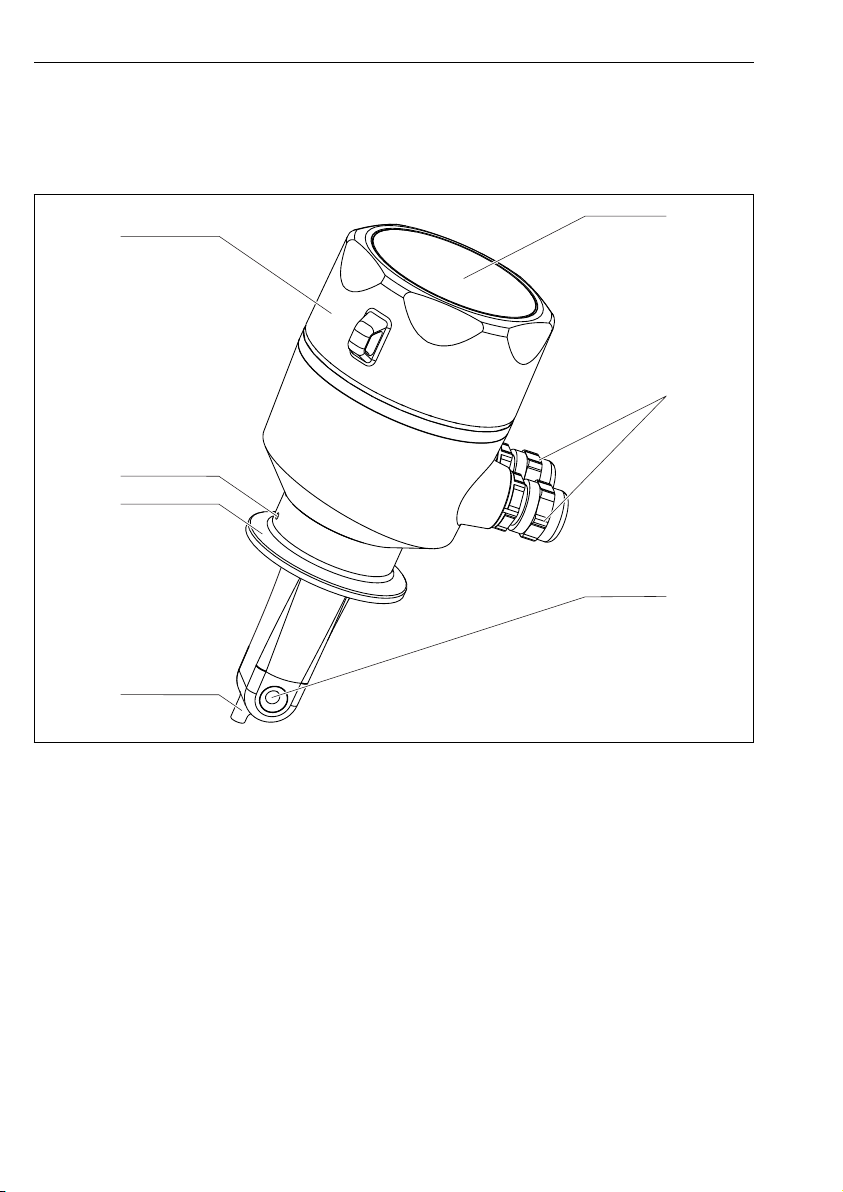
3 Product description
3.1 Product design
1 Elements
1 Temperature sensor
2 Process connection
3 Leakage bore (offset by 90° in relation to the flow direction)
4 Removable housing cover
5 Window for display
6 Cable glands (M12)
7 Flow opening of sensor
8 Endress+Hauser
A0019184
Page 9

Smartec CLD18 Incoming acceptance and product identification
4 Incoming acceptance and product identification
4.1 Incoming acceptance
1. Verify that the packaging is undamaged.
Notify the supplier of any damage to the packaging.
Keep the damaged packaging until the issue has been resolved.
2. Verify that the contents are undamaged.
Notify the supplier of any damage to the delivery contents.
Keep the damaged goods until the issue has been resolved.
3. Check that the delivery is complete and nothing is missing.
Compare the shipping documents with your order.
4. Pack the product for storage and transportation in such a way that it is protected
against impact and moisture.
The original packaging offers the best protection.
Make sure to comply with the permitted ambient conditions.
If you have any questions, please contact your supplier or your local Sales Center.
Technical data→ 40
4.2 Product identification
4.2.1 Nameplate
The nameplate provides you with the following information on your device:
• Manufacturer identification
• Order code
• Extended order code
• Serial number
• Firmware version
• Ambient and process conditions
• Input and output values
• Measuring range
• Safety information and warnings
• Protection class
Compare the information on the nameplate with the order.
‣
Endress+Hauser 9
Page 10

Incoming acceptance and product identification Smartec CLD18
4.2.2 Product identification
Product page
www.endress.com/CLD18
Interpreting the order code
The order code and serial number of your product can be found in the following locations:
• On the nameplate
• In the delivery papers
Obtaining information on the product
1. Go to www.endress.com.
2. Call up the site search (magnifying glass).
3. Enter a valid serial number.
4. Search.
The product structure is displayed in a popup window.
5. Click on the product image in the popup window.
A new window (Device Viewer) opens. All of the information relating to your
device is displayed in this window as well as the product documentation.
Manufacturer's address
Endress+Hauser Conducta GmbH+Co. KG
Dieselstraße 24
D-70839 Gerlingen
4.3 Scope of delivery
The delivery comprises:
• A Smartec CLD18 measuring system in the version ordered
• Operating Instructions BA01149C/07/EN
10 Endress+Hauser
Page 11

Smartec CLD18 Installation
4.4 Certificates and approvals
4.4.1 Declaration of Conformity
The product meets the requirements of the harmonized European standards. As such, it
complies with the legal specifications of the EU directives. The manufacturer confirms
successful testing of the product by affixing to it the mark.
4.4.2 Hygiene FDA
All materials in contact with the product are FDA-listed materials (apart from the PVC process
connections).
EHEDG
Certified cleanability according to EHEDG Type EL Class I.
When using the sensor in hygienic applications, please note that the cleanability of the
sensor also depends on the way the sensor is installed. To install the sensor in a pipe, use
the appropriate and EHEDG-certified flow vessels for the particular process connection.
3-A
Certified according to 3-A Standard 74- ("3-A Sanitary Standards for Sensor and Sensor
Fittings and Connections Used on Milk and Milk Products Equipment").
EC Regulation No. 1935/2004
The sensor meets the requirements of EC Regulation No. 1935/2004 on materials and articles
intended to come into contact with food.
4.4.3 Pressure approval
Canadian pressure approval for pipes according to ASME B31.3
5 Installation
5.1 Installation conditions
5.1.1 Installation instructions
For a 3-A compliant installation, the following must be noted:
After the instrument is installed its hygienic integrity shall be maintained. The
instrument shall be installed with the leakage detection at the lowest point of the
assembly. Furthermore all process connections must be 3-A compliant.
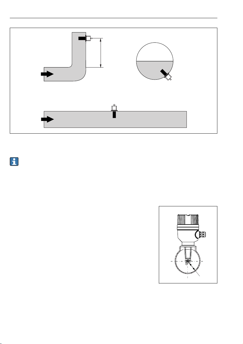
Orientations
The sensor must be completely immersed in the medium. Avoid air bubbles in the area of the
sensor.
Endress+Hauser 11
Page 12
Installation Smartec CLD18
> 1 (3.3)
a
A0037970
2 Orientation of conductivity sensors. Engineering unit: m (ft)
If the flow direction changes (after pipe bends), turbulence in the medium can result.
Install the sensor at a distance of at least 1 m (3.3 ft) downstream from a pipe bend.
‣
The product should flow along the hole of the sensor (see the arrows on the housing). The
symmetrical measuring channel allows flow in both directions.
In confined installation conditions, the walls affect the ionic
current in the liquid. This effect is offset by what is referred to
as the installation factor. The installation factor can be entered
in the transmitter for the measurement or the cell constant is
corrected by multiplying by the installation factor.
The value of the installation factor depends on the diameter
and the conductivity of the pipe nozzle as well as the distance a
between the sensor and the wall.
The installation factor can be disregarded (f = 1.00) if the
distance to the wall is sufficient (a > 20 mm, from DN 60).
If the distance to the wall is smaller, the installation factor
increases for electrically insulating pipes (f > 1) and decreases
for electrically conductive pipes (f < 1).
It can be measured using calibration solutions, or a close
approximation can be determined from the following diagram.
12 Endress+Hauser
A0037972
3 Installation of CLD18
a Wall distance
Page 13
Smartec CLD18 Installation
1
2
a [inch]
0
10
20 30
40
a [mm]
0.95
1 00.
1.05
f
0.39
0.79
1.18
1.57
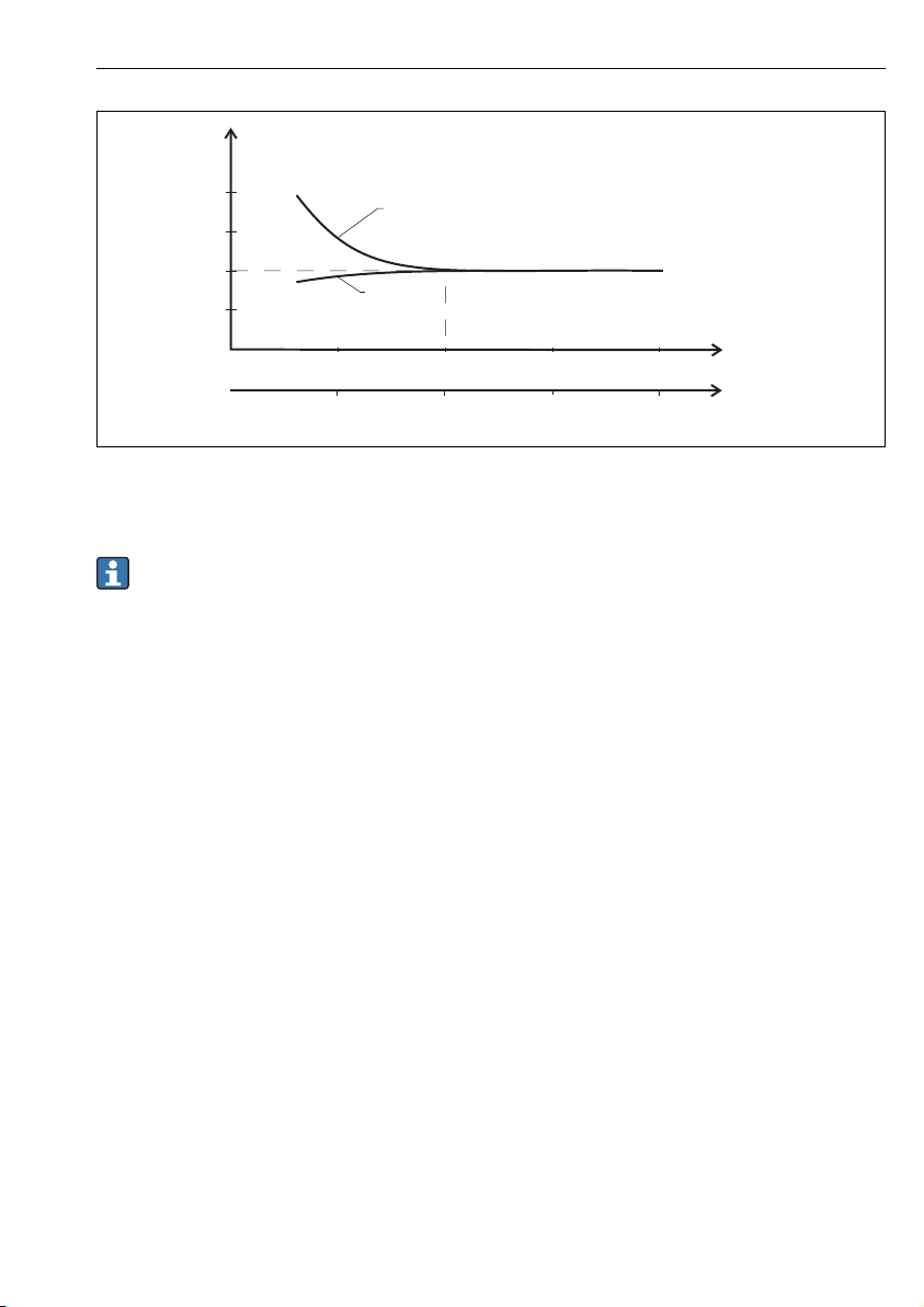
A0020517
4 Relationship between installation factor f and wall distance a
1 Electrically conductive pipe wall
2 Electrically insulating pipe wall
Install the measuring system in such a way that the housing is not exposed to direct
sunlight.
Endress+Hauser 13
Page 14
Installation Smartec CLD18
28 (1.10)
73.5
(0.91)
86 (3.39)
136.5 (5.37)
101.7 (4.00)
28 (1.10)
78 (3.07)
85 (3.35)
6
53.3
(2.10)
127 (5.00)
69 (2.72)
112 (4.41)
85 (3.35)
114.5 (4.51)
53.3
(2.10)
69
(2.72)
5.2
20.5
(0.81)
123 (4.84)
12.3 (0.49)
17.1 (0.67)
32.8 (1.29)
123 (4.84)
A A
B B
C
D
(0.24)
(2.89)
(0.20)
23
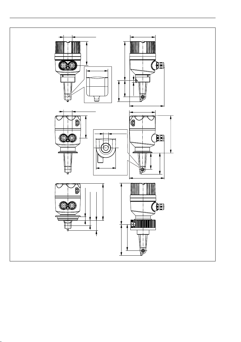
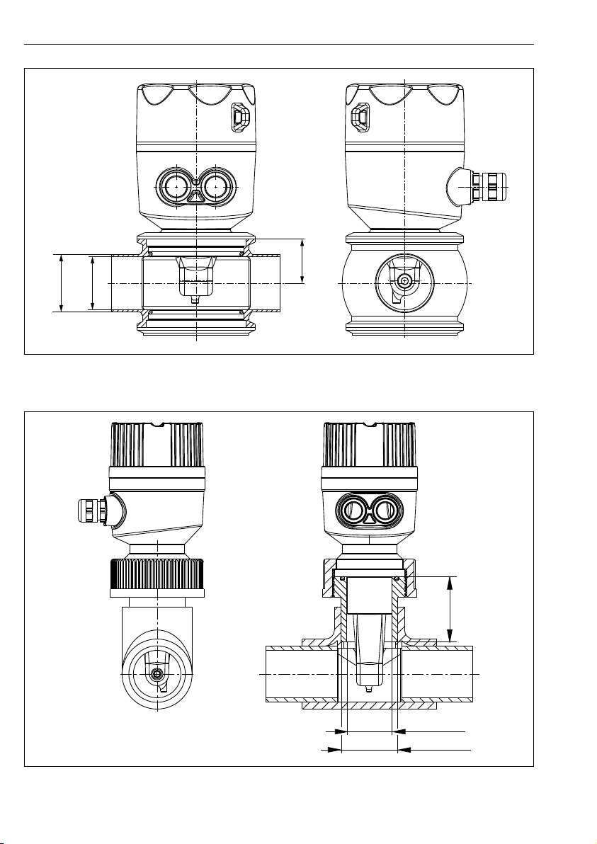
5 Dimensions and versions (examples). Dimensions: mm (in)
A Plastic housing with thread G 1½
B Stainless steel housing with ISO 2852 clamp 2"
C Stainless steel housing with Varivent DN 40 to 125
D Plastic housing with coupling nut 2¼" PVC
A0018942
14 Endress+Hauser
Page 15
Smartec CLD18 Installation
51 (2.01)
Ø 44.3
(1.74)
Ø 48.3
(1.90)
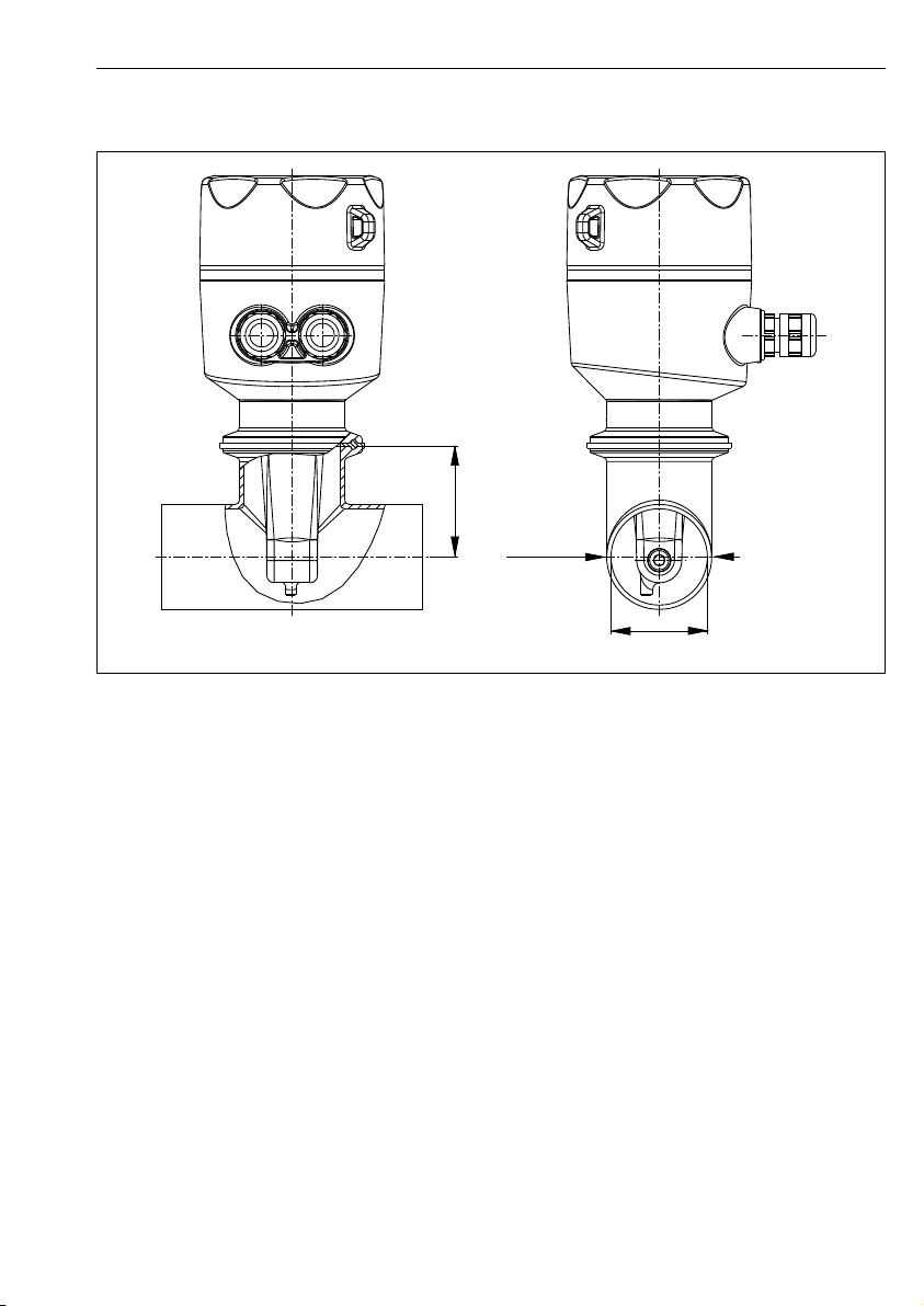
5.1.2 Installation examples
A0019302
6 Installation in DN 40 pipe with Tri-Clamp 2" process connection. Dimensions: mm (in)
Endress+Hauser 15
Page 16
Installation Smartec CLD18
31
(1.22)
Ø 38
(1.50)
Ø 41
(1.61)
57.5
(2.26)
Ø 40 (1.58)
Ø 50 (1.97)
A0022166
7 Installation in DN 40 pipe with Varivent process connection. Dimensions: mm (in)
8 Installation in DN 40 pipe with 2¼" PVC coupling nut process connection. Dimensions: mm (in)
16 Endress+Hauser
A0024073
Page 17

Smartec CLD18 Electrical connection
5.2 Mounting the compact device
Choose the installation depth of the sensor in the medium such that the coil body is
‣
completely immersed in the medium.
Pay attention to the information on wall clearance → 11
1. Mount the compact device directly on a pipe nozzle or tank nozzle via the process
connection.
2. For the 1½" threaded connection, use a Teflon tape to seal the connection and an
adjustable pin wrench (DIN 1810, flat face, size 45 to 50 mm (1.77 to 1.97 in)) to
tighten it.
3. When installing, align the compact device in such a way that the medium flows through
the flow opening of the sensor in the direction of medium flow. Use the arrow on the
nameplate to help you align the device.
4. Tighten the flange.
5.3 Post-installation check
1. Following installation, check the compact device for damage.
2. Ensure that the compact device is protected against direct sunlight.
6 Electrical connection
WARNING
L
Device is live!
Incorrect connection may result in injury or death!
The electrical connection may be performed only by an electrical technician.
‣
The electrical technician must have read and understood these Operating Instructions and
‣
must follow the instructions contained therein.
Prior to commencing connection work, ensure that no voltage is present on any cable.
‣
6.1 Connecting the transmitter
WARNING
L
Risk of electric shock!
At the supply point, the power supply must be isolated from dangerous live cables by
‣
double or reinforced insulation in the case of devices with a 24 V power supply.
Endress+Hauser 17
Page 18

Electrical connection Smartec CLD18
Lf
mA
mA
X
I ut1O
I ut2O
L
MRS
Alarm Out
6.1.1 Direct connection of the cables
A0033106
9 Electrical connection
18 Endress+Hauser
Page 19

Smartec CLD18 Electrical connection
-
+
L
L
L+
L-
Out+
Out-
MRS+
MRS-
I ut1-O
I ut2+O
I ut1+O
I ut2-O
X
1
2
A0029684
10 Terminal assignment
IOut1
Current output conductivity (active)
IOut2 Current output temperature (active)
Out Alarm output (open-collector)
MRS Binary input (measuring range switch)
L+/L- Power supply
X Grounding pin (flat male tab 4.8 mm)
1 Cover on electronics box
2 Electronics box
NOTICE
Removing the electronics box will destroy the sensor connection!
The electronics box must not be removed under any circumstances.
‣
Do not open the cover on the electronics box.
‣
The recommended cable cross-section for the connecting cables is 0.5 mm2. The
maximum cable cross-section is 1.0 mm2.
Connect the transmitter of the compact device as follows:
1. Unscrew the housing cover.
Endress+Hauser 19
Page 20

Electrical connection Smartec CLD18
3
2
1
4
4
3
2
1
7
6
5
8
2. Guide the connecting cables through the cable glands.
3. Connect the cables as per the terminal assignment diagram.
4. Connect the protective ground to the terminal pin for the housing ground.
6.1.2 Connection via M12 connector
A0033108
11 View of connector, 4-pin, data cable (at device)
1 IOUT1+ Conductivity 3 IOUT2- Temperature
2 IOUT2+ Temperature 4 IOUT1- Conductivity
12 View of connector, 8-pin, power supply/controller (at device)
1 L+ Power supply 5 Out+ Alarm output+
2 L- Power supply 6 Out- Alarm output3 MRS+ Binary input 7 GND Functional ground
4 MRS- Binary input 8 GND Functional ground
20 Endress+Hauser
A0033109
Page 21

Smartec CLD18 Electrical connection
6.2 Ensuring the degree of protection
Guarantee the degree of protection as follows:
1. Verify that the O-ring is seated correctly in the housing cover.
2. Screw the housing cover tight until the stop.
3. Screw the cable glands tight.
6.3 Post-connection check
Once you have performed the electrical connections, carry out the following checks :
Instrument status and specifications Notes
Are the transmitter and cables free from damage on the outside? Visual inspection
Electrical connection Notes
Are the installed cables strain-relieved and not twisted?
Is the cable run correct, without loops and cross-overs?
Are the signal cables correctly connected as per the wiring diagram?
Are all the cable entries fitted, tightened and leak-proof?
Are the PE distributor blocks grounded (if present)? Grounding is carried out at the point
of installation.
Endress+Hauser 21
Page 22

Operation options Smartec CLD18
E
+
_
ESC
- -
Main µS/cm
1
2
3
4
7 Operation options
13 Display and keys of the CLD18
1 Parameters
2 Measured value
3 Unit
4 Operating keys
The ASTN display (Advanced Super Twisted Nematic) is split into two sections. The segment
section displays the measured value. The dot-matrix section displays the parameter and unit.
The operating texts are displayed in English.
In the event of an error the device automatically alternates between displaying the error and
the measured value.
A0018963
22 Endress+Hauser
Page 23

Smartec CLD18 Operation options
E
7.1 Overview of operating options
• Open the Configuration menu
• Confirm the entry
• Select a parameter or submenu
A0029236
Within the Configuration menu:
• Gradually select the specified menu items / characters for the
parameter
• Change the selected parameter
A0029235
Outside the Configuration menu:
Display enabled and calculated channels, as well as minimum and
maximum values, for all the active channels.
Press both keys simultaneously (< 3 s) to quit the setup without
saving any changes.
Always quit menu items / submenus at the end of the menu via "x Back".
Symbols in the editing mode:
Accept entry.
A0020597
If this symbol is selected, the entry is applied at the position specified by the user, and you quit editing mode.
Reject entry.
If this symbol is selected, the entry is rejected and you quit editing mode. The previously set text remains.
A0020598
Jump one position to the left.
A0020599
If this symbol is selected, the cursor jumps one position to the left.
Delete backwards.
If this symbol is selected, the character to the left of the cursor position is deleted.
A0020600
Delete all.
if this symbol is selected, the entire entry is deleted.
A0020601
Endress+Hauser 23
Page 24

Operation options Smartec CLD18
7.2 Structure and function of the operating menu
The operating functions of the compact measuring device are divided into the following
menus:
Display Settings for the device display: contrast, brightness, time for alternating measured values on the display
Setup Device settings
Calibration Perform sensor calibration*
Diagnostics Device information, diagnostics logbook, sensor information, simulation
* The air set and the correct cell constant have already been configured at the factory for the
Smartec CLD18. A sensor calibration is not necessary during commissioning.
24 Endress+Hauser
Page 25

Smartec CLD18 Commissioning
8 Commissioning
8.1 Switching on the measuring device
1. Familiarize yourself with the operation of the transmitter before it is first switched on.
After power-up, the device performs a self-test and then goes to the measuring
mode.
2. If you are commissioning the device for the first time, Setup program the as described in
the following sections of the Operating Instructions.
8.2 Display settings (Display menu)
1. Use the 'E' key to call up the main menu.
The menu appears on the display Display.
2. Press the 'E' key again to open the menu.
3. Use the option, Back which can be found at the bottom of each menu, to move up a
level in the menu structure.
Parameter Possible settings Description
Contrast 1 to 7
Default: 5
Brightness 1 to 7
Default: 5
Alternating time 0, 3, 5, 10 s
Default: 5
Setting for the contrast
Setting for the brightness of the display
Alternating time between the two measured values
0 means that the values do not alternate on the display
Endress+Hauser 25
Page 26

Commissioning Smartec CLD18
8.3 Configuring the measuring device
1. Use the 'E' key to call up the main menu.
2. Navigate through the available menus with the '+' and '–' keys.
3. Press the 'E' key to open the desired menu.
4. Use the option, Back which can be found at the bottom of each menu, to move up a
level in the menu structure.
Default settings are in bold.
Parameter Possible settings Description
Current range 4-20 mA
0-20 mA
Out1 0/4 mA 0 to 2000000 μS/cm
0 μS/cm
Out1 20 mA 0 to 2000000 μS/cm
0 μS/cm
Select the current range.
‣
Enter the measured value at which the min. current value (0/4 mA) is
‣
present at the transmitter output.
Enter the measured value at which the max. current value (20 mA) is
‣
present at the transmitter output.
Out2 0/4 mA -50 to 250 °C
0.0 °C
Out2 20 mA -50 to 250 °C
100.0 °C
Damping main 0 ... 60 s
0 s
Extended setup
Manual hold Off, On Function for freezing the current and alarm outputs
Enter the measured value at which the min. current value (0/4 mA) is
‣
present at the transmitter output.
Enter the measured value at which the max. current value (20 mA) is
‣
present at the transmitter output.
Damping value for the conductivity measured value
Advanced settings→ 26
8.4 Advanced settings
1. Use the 'E' key to call up the main menu.
2. Navigate through the available menus with the '+' and '–' keys.
3. Press the 'E' key to open the desired menu.
4. Use the option, Back which can be found at the bottom of each menu, to move up a
level in the menu structure.
Default settings are in bold.
Parameter Possible settings Description
System General settings
Device tag Customized text
Max. 16 characters
Enter the device designation
26 Endress+Hauser
Page 27

Smartec CLD18 Commissioning
Parameter Possible settings Description
Temp. unit °C
°F
Hold release 0 to 600 s
0 s
Alarm delay 0 to 600 s
0 s
Input Setting for the inputs
Cell const. Read only Displays the cell constant
Inst. factor 0.1 to 5.0
1.0
Unit Auto, μS/cm, mS/cm Unit of conductivity
Damping main 0 ... 60 s
0 s
Temp. comp. Off, Linear Setting for temperature compensation
Alpha coeff. 1.0 to 20.0 %/K
2.1 %/K
Ref. temp. +10 to +50 °C
25 °C
Process check The process check checks the measuring signal for stagnation. An
Function On, Off
Duration 1 to 240 min
60 min
Observation width 1 to 20 %
0.0 %
Analog output Setting for analog outputs
Current range 4-20 mA
0-20 mA
Out1 0/4 mA 0 to 2000000 μS/cm
0 μS/cm
Out1 20 mA 0 to 2000000 μS/cm
0 μS/cm
Out2 0/4 mA -50 to 250 °C
0.0 °C
Out2 20 mA -50 to 250 °C
100.0 °C
Setting for the temperature unit
Prolongs the device hold when the hold condition no longer
applies
Time delay after which an alarm is output
This suppresses alarm conditions that are present for a period
that is shorter than the alarm delay time.
The effects of the distance from the wall can be corrected
with the installation factor → 29
"auto" automatically switches between μS/cm and mS/cm.
Setting for the damping
Coefficient for linear temperature compensation
Enter the reference temperature
alarm is triggered if the measuring signal does not change over a
specific period (several measured values).
Switch the process check on or off.
‣
The measured value must change within this time as otherwise
an error message is triggered.
Bandwidth for the process check
Current range for analog output
Enter the measured value at which the min. current value
‣
(0/4 mA) is present at the transmitter output.
Enter the measured value at which the max. current value
‣
(20 mA) is present at the transmitter output.
Enter the measured value at which the min. current value
‣
(0/4 mA) is present at the transmitter output.
Enter the measured value at which the max. current value
‣
(20 mA) is present at the transmitter output.
Endress+Hauser 27
Page 28

Commissioning Smartec CLD18
Parameter Possible settings Description
MRS
Setting for measuring range switching → 31
Out1 0/4 mA 0 to 2000000 μS/cm
0 μS/cm
Out1 20 mA 0 to 2000000 μS/cm
0 μS/cm
Out2 0/4 mA -50 to 250 °C
0.0 °C
Out2 20 mA -50 to 250 °C
100.0 °C
Damping main 0 ... 60 s
0 s
Alpha coeff. 1.0 to 20 %/K
2.1 %/K
Factory default Factory settings
Please confirm No
No, Yes
Enter the measured value at which the min. current value
‣
(0/4 mA) is present at the transmitter output.
Enter the measured value at which the max. current value
‣
(20 mA) is present at the transmitter output.
Enter the measured value at which the min. current value
‣
(0/4 mA) is present at the transmitter output.
Enter the measured value at which the max. current value
‣
(20 mA) is present at the transmitter output.
Setting for the damping
Coefficient for linear temperature compensation
28 Endress+Hauser
Page 29

Smartec CLD18 Commissioning
1
2
a [inch]
0
10
20 30
40
a [mm]
0.95
1 00.
1.05
f
0.39
0.79
1.18
1.57
8.4.1 Installation factor
In confined installation conditions, the conductivity measurement in the liquid is affected by
the pipe walls. This effect is offset by the installation factor. The cell constant is corrected by
multiplying by the installation factor.
The value of the installation factor depends on the diameter and the conductivity of the pipe
nozzle as well as the sensor's distance to the wall.
The installation factor f (f = 1.00) can be disregarded if the distance to the wall is sufficient
(a>20 mm (0.79 in), from DN60).
If the distance to the wall is small, the installation factor increases for electrically insulating
pipes (f > 1), and decreases for electrically conductive pipes (f < 1).
It can be measured using calibration solutions, or a close approximation determined from the
following diagram.
14 Relationship between the installation factor (f) and the distance from wall (a)
1 Electrically conductive pipe wall
2 Electrically insulating pipe wall
Endress+Hauser 29
A0020517
Page 30

Commissioning Smartec CLD18
k(T) k(T )
0
(1+
=
(T - T ))
0
a
.
.
8.4.2 Temperature compensation
The conductivity of a liquid depends heavily on the temperature, as the mobility of the ions
and the number of dissociated molecules are temperature-dependent. In order to compare
measured values, they must be referenced to a defined temperature. The reference
temperature is 25 °C (77 °F).
The temperature is always specified when the conductivity is specified. k(T0) represents the
conductivity measured at 25 °C (77 °F) or referenced back to 25 °C (77 °F).
The temperature coefficient α represents the percentage change in the conductivity per degree
of temperature change. The conductivity k at the process temperature is calculated as follows:
A0009163
Where
k(T) = conductivity at process temperature T
k(T0) = conductivity at process temperature T
0
The temperature coefficient depends on both the chemical composition of the solution and on
the temperature, and is between 1 and 5 % per °C. The electrical conductivity of the majority
of diluted saline solutions and natural waters changes in a close-to-linear fashion.
Typical values for the temperature coefficient α:
Natural waters
Approx. 2 %/K
Salts (e.g. NaCl) Approx. 2.1 %/K
Alkali (e.g. NaOH) Approx. 1.9 %/K
Acids (e.g. HNO3) Approx. 1.3 %/K
30 Endress+Hauser
Page 31

Smartec CLD18 Commissioning
8.4.3 Measuring range switch (MRS)
Measuring range switching involves a parameter set changeover for two substances:
• in order to cover a large measuring range
• in order to adjust temperature compensation in the event of a product change
The two analog outputs can each be configured with two parameter sets.
• Parameter set 1:
• The parameters for the current outputs and the damping can be set Setup in the menu.
• The alpha coefficient for temperature compensation can be set Setup/Extended setup/
Input in the menu.
• Parameter set 1 is active if the "MRS" binary input is Low .
• Parameter set 2:
• The parameters for the current outputs, the damping and the alpha coefficient for
temperature compensation can be configured Setup/Extended setup/Remote switch in
the menu.
• Parameter set 2 is active if the "MRS" binary input High is .
The settings for parameter set 1 are also listed in Extended setup/Analog output the
menu.
Technical data→ 41
8.5 Calibration (Calibration menu)
In the case of the Smartec CLD 18, the air set and the correct cell constant have already been
configured at the factory. A sensor calibration is not necessary during commissioning.
8.5.1 Types of calibration
The following types of calibration are possible:
• Cell constant with calibration solution
• Air set (residual coupling)
8.5.2 Cell constant
General
The calibration of a conductivity measuring system is always performed in such a way that the
suitable calibration solutions determine or verify the exact cell constant. This process is
described in the standards EN 7888 and ASTM D 1125, for example, and the method for
producing a number of calibration solutions is explained.
Endress+Hauser 31
Page 32

Commissioning Smartec CLD18
Calibrating the cell constant
With this type of calibration, enter a reference value for the conductivity.
‣
In the result, the device calculates a new cell constant for the sensor.
First switch off the temperature compensation:
1. Select the menu Setup/Extended setup/Input/Temp. comp. .
2. Off Select .
3. Return to the menu Setup .
Perform the calculation of the cell constant as follows:
1. Select the menu Calibration/Cell const. .
2. Cond. ref. Select and enter the value of the standard solution.
3. Place the sensor in the medium.
4. Start the calibration.
"Wait calib." - wait for calibration to end. The new value is displayed after the
calibration.
5. Press the Plus key.
"Save calib data?"
6. Yes Select .
"Calib successful"
7. Switch the temperature compensation back on.
32 Endress+Hauser
Page 33

Smartec CLD18 Commissioning
8.5.3 Air set (residual coupling)
For physical reasons, the calibration line goes through zero in the case of conductive sensors
(a current flow of 0 corresponds to a conductivity of 0). When working with inductive sensors,
the residual coupling between the primary coil (transmitter coil) and secondary coil (receiver
coil) must be taken into account or compensated for. The residual coupling is not only caused
by the direct magnetic coupling of the coils but also by crosstalk in the supply cables.
As is the case with the sensors, the cell constant is then determined using a precise calibration
solution.
To perform an airset, the sensor must be dry.
Perform an airset as follows:
1. Calibration/Airset Select .
The current value is displayed.
2. Press the Plus key.
"Keep sensor in air"
3. Keep the dried sensor in air and press the Plus key.
"Wait calib." - wait for calibration to end. The new value is displayed after the
calibration.
4. Press the Plus key.
"Save calib data?"
5. Yes Select .
"Calib successful"
6. Press the Plus key.
The device switches back to the measuring mode.
Endress+Hauser 33
Page 34

Diagnostics and troubleshooting Smartec CLD18
9 Diagnostics and troubleshooting
9.1 General troubleshooting
User interface Cause Solution
No measured value displayed No power supply connected Check the device's power supply.
Power is supplied, device is defective The device must be replaced.
Diagnostic message is displayed
9.2 Troubleshooting instructions
1. Use the 'E' key to call up the main menu.
2. Navigate through the available menus with the '+' and '–' keys.
3. Press the 'E' key to open the desired menu.
4. Use the option, Back which can be found at the bottom of each menu, to move up a
level in the menu structure.
Parameter Possible settings Description
Current diag. Read only Displays the current diagnostic message
Last diag. Read only Displays the last diagnostic message
Diag. logbook Read only Displays the last diagnostic messages
Device info Read only Displays device information
Sensor info Read only Displays sensor information
Simulation
Analog out 1 Off
0 mA, 3.6 mA, 4 mA, 10 mA, 12 mA,
20 mA, 21 mA
Analog out 2 Off
0 mA, 3.6 mA, 4 mA, 10 mA, 12 mA,
20 mA, 21 mA
Alarm out Off
Active
Inactive
Reset device
Diagnostic messages → 35
Outputs a corresponding value at the "Analog out 1"
output.
Outputs a corresponding value at the "Analog out 2"
output.
34 Endress+Hauser
Page 35

Smartec CLD18 Diagnostics and troubleshooting
9.3 Queued diagnostic messages
The diagnostic message consists of a diagnostic code and a message text. The diagnostic code
consists of the error category as per Namur NE 107 and the message number.
Error category (letter in front of the message number):
• F = Failure, a malfunction has been detected
The measured value of the affected channel is no longer reliable. Look for the cause in the
measuring point. If a control system is connected, it must be switched to manual mode.
• M = Maintenance required, action should be taken as soon as possible
The device still measures correctly. Immediate measures are not necessary. Proper
maintenance efforts may prevent a possible malfunction in the future.
• C = Function check, waiting (no error)
Maintenance work is being performed on the device. Wait until the work has been
completed.
• S = Out of specification, the measuring point is being operated outside your specification
Operation is still possible. However, you run the risk of increased wear, shorter operating
life or reduced measurement accuracy. Look for the cause in the measuring point.
Diagnostic code Message text Description
F61 Sensor elec. Sensor electronics defective
Remedy:
Contact the Service Department
F62 Sens. Connect Sensor connection
Remedy:
Contact the Service Department
F100 Sensor comm. Sensor not communicating
Possible reasons:
No sensor connection
Remedy:
Contact the Service Department
F130 Sensor supply Sensor check
F143 Selftest Sensor self-test error
F152 No airset Sensor data
No conductivity displayed
Possible reasons:
• Sensor in air
• Sensor defective
Remedy:
• Check sensor installation
• Contact the Service Department
Remedy:
Contact the Service Department
No calibration data available
Remedy:
Perform an air set
Endress+Hauser 35
Page 36

Diagnostics and troubleshooting Smartec CLD18
Diagnostic code Message text Description
F523 Cell constant Sensor calibration warning
F524 Cell constant Sensor calibration warning
F845 Device id Incorrect hardware configuration
F847 Couldn’t save param Incorrect parameters
F848 Calib AO1 Incorrect calibration values for analog output 1
F849 Calib AO2 Incorrect calibration values for analog output 2
F904 Process check Process check system alarm
Invalid cell constant, max. range reached
Remedy:
• Enter cell constant as per factory specifications
• Contact the Service Department
Min. possible cell constant is undershot
Remedy:
• Enter cell constant as per factory specifications
• Contact the Service Department
Measuring signal has not changed for a long time
Possible reasons:
• Contaminated sensor, or sensor in air
• No flow to sensor
• Sensor defective
• Software error
Remedy:
• Check electrode system
• Check sensor
• Restart device
Diagnostic code Message text Description
C107 Calib. active Sensor calibration is active
Remedy:
Wait for calibration to be finished
C154 No calib. data Sensor data
C850 Simu AO1 Simulation of analog output 1 is active
C851 Simu AO2 Simulation of analog output 2 is active
36 Endress+Hauser
No calibration data available, factory settings are used
Remedy:
• Check the calibration information of the sensor
• Contact the Service Department
Page 37

Smartec CLD18 Diagnostics and troubleshooting
Diagnostic code Message text Description
S844 Process value Measured value outside the specified range
Possible reasons:
• Sensor in air
• Incorrect flow to sensor
• Sensor defective
Remedy:
• Increase process value
• Check electrode system
Diagnostic code Message text Description
M500 Not stable Sensor calibration aborted
M526 Cell constant Sensor calibration warning
M528 Cell constant Sensor calibration warning
Main measured value fluctuating
Possible reasons:
• Sensor in air
• Sensor fouled
• Incorrect flow to sensor
• Sensor defective
Remedy:
• Check sensor
• Check installation
Invalid cell constant, max. range reached
Remedy:
• Repeat the calibration
• Enter cell constant as per factory specifications
• Contact the Service Department
Min. possible cell constant is undershot
Remedy:
• Repeat the calibration
• Enter cell constant as per factory specifications
• Contact the Service Department
Endress+Hauser 37
Page 38

Maintenance Smartec CLD18
10 Maintenance
WARNING
L
Risk of injury if medium escapes!
Before each maintenance task, ensure that the process pipe is unpressurized, empty and
‣
rinsed.
The electronics box does not contain any parts that the user must maintain.
• The cover on the electronics box may be opened only by Endress+Hauser Service staff.
• The electronics box may be removed only by Endress+Hauser Service staff.
10.1 Maintenance tasks
10.1.1 Cleaning the housing
Clean the front of the housing using commercially available cleaning agents only.
‣
The front of the housing is resistant to the following in accordance with DIN 42 115:
• Ethanol (for a short time)
• Diluted acids (max. 2% HCl)
• Diluted bases (max. 3% NaOH)
• Soap-based household cleaning agents
When performing any work on the device, bear in mind any potential impact this may have
‣
on the process control system or on the process itself.
NOTICE
Prohibited cleaning agents!
Damage to the housing surface or housing seal
Never use concentrated mineral acids or alkaline solutions for cleaning.
‣
Never use organic cleaners such as benzyl alcohol, methanol, methylene chloride, xylene or
‣
concentrated glycerol cleaner.
Never use high-pressure steam for cleaning.
‣
38 Endress+Hauser
Page 39

Smartec CLD18 Repair
11 Repair
The O-ring is defective if medium escapes from the leakage hole.
Contact the E+H Service department to replace the O-ring.
‣
11.1 General notes
Only use spare parts from Endress + Hauser to guarantee the safe and stable functioning of
‣
the device.
Detailed information on the spare parts is available at:
www.endress.com/device-viewer
11.2 Return
The product must be returned if repairs or a factory calibration are required, or if the wrong
product was ordered or delivered. As an ISO-certified company and also due to legal
regulations, Endress+Hauser is obliged to follow certain procedures when handling any
returned products that have been in contact with medium.
To ensure the swift, safe and professional return of the device:
Refer to the website www.endress.com/support/return-material for information on the
‣
procedure and conditions for returning devices.
11.3 Disposal
The device contains electronic components. The product must be disposed of as electronic
waste.
Observe the local regulations.
‣
Endress+Hauser 39
Page 40

Accessories Smartec CLD18
12 Accessories
The following are the most important accessories available at the time this documentation
was issued.
For accessories not listed here, please contact your Service or Sales Center.
‣
12.1 Calibration solutions
Conductivity calibration solutions CLY11
Precision solutions referenced to SRM (Standard Reference Material) by NIST for qualified
calibration of conductivity measuring systems in accordance with ISO 9000:
• CLY11-C, 1.406 mS/cm (reference temperature 25 °C (77 °F)), 500 ml (16.9 fl.oz)
Order No. 50081904
• CLY11-D, 12.64 mS/cm (reference temperature 25 °C (77 °F)), 500 ml (16.9 fl.oz)
Order No. 50081905
• CLY11-E, 107.00 mS/cm (reference temperature 25 °C (77 °F)), 500 ml (16.9 fl.oz)
Order No. 50081906
For further information on "Calibration solutions", see the Technical Information
13 Technical data
13.1 Input
13.1.1 Measured variable
Conductivity
Temperature
13.1.2 Measuring range
Conductivity:
Temperature: –10 to 130 °C (14 to 266 °F)
40 Endress+Hauser
Recommended range: 200 μS/cm to 1000 mS/cm
(uncompensated)
Page 41

Smartec CLD18 Technical data
13.1.3 Binary input
The binary input is used for measuring range switching.
Voltage range 0 V to 30 V
Voltage High Min. 12 V
Voltage Low max. 9.0 V
Current consumption at 24 V 30 mA
Undefined voltage range 9.0 to 12 V
13.2 Output
13.2.1 Output signal
Conductivity:
Temperature: 0 / 4 to 20 mA, galvanically isolated
13.2.2 Load
Max. 500 Ω
13.2.3 Characteristic
Linear
13.2.4 Signal resolution
Resolution:
Accuracy: ± 20 μA
13.2.5 Alarm output
The alarm output is implemented as an "open collector".
Max. current
Max. voltage 30 V DC
Error or device without supply voltage Alarm output blocked (0 mA)
No error Alarm output open (up to 200 mA)
0 / 4 to 20 mA, galvanically isolated
> 13 bit
200 mA
13.3 Power supply
13.3.1 Supply voltage
24 V DC ± 20 %, protected against reverse polarity
13.3.2 Power consumption
3 W
Endress+Hauser 41
Page 42

Technical data Smartec CLD18
13.3.3 Cable specification
Recommendation 0.5 mm
max. 1.0 mm
2
2
13.3.4 Overvoltage protection
Overvoltage category I
13.4 Performance characteristics
13.4.1 Response time
Conductivity: t95 < 1.5 s
Temperature: t90 < 20 s
13.4.2 Maximum measured error
Conductivity:
Temperature: ± 1.5 K
Signal outputs ± 50 μA
13.4.3 Repeatability
Conductivity:
13.4.4 Cell constant
11.0 cm
-1
± (2.0 % of measured value + 20 µS/cm)
max. 0.5 % of measured value ± 5 µS/cm ± 2 digits
13.4.5 Temperature compensation
Range
–10 to 130 °C (14 to 266 °F)
Types of compensation • None
• Linear with user-configurable temperature
coefficient
13.4.6 Reference temperature
25 °C (77 °F)
13.5 Environment
13.5.1 Ambient temperature range
Stainless steel process connection:
PVC process connection: –10 to 60 °C (14 to 60 °F)
42 Endress+Hauser
–20 to 60 °C (–4 to 140 °F)
Page 43

Smartec CLD18 Technical data
13.5.2 Storage temperature
Stainless steel process connection: –25 to 80 °C (–13 to 176 °F)
PVC process connection: –10 to 60 °C (14 to 140 °F)
13.5.3 Humidity
≤ 100 %, condensating
13.5.4 Climate class
Climate class 4K4H as per EN 60721-3-4
13.5.5 Degree of protection
IP 69k as per EN 40050:1993
Degree of protection NEMA TYPE 6P as per NEMA 250-2008
13.5.6 Shock resistance
Complies with IEC 61298-3, certified up to 5 g
13.5.7 Vibration resistance
Complies with IEC 61298-3, certified up to 5 g
13.5.8 Electromagnetic compatibility
Interference emission as per EN 61000-6-3:2007 + A1:2011 and EN 55011:2009 + A1:2010
Interference immunity as per EN 61326-1:2013
13.5.9 Degree of contamination
Pollution level 2
13.5.10 Altitude
<2000 m (6500 ft)
13.6 Process
13.6.1 Process temperature
Stainless steel process connection:
–10 to 110 °C (14 to 230 °F)
Max.130 °C (266 °F) up to 60 minutes
PVC process connection:
–10 to 60 °C (14 to 140 °F)
13.6.2 Absolute process pressure
Stainless steel process connection:
13 bar (188.5 psi), abs to up to 50 °C (122 °F)
Endress+Hauser 43
Page 44

Technical data Smartec CLD18
p (abs.)
T
[bar]
[°C]
6
13
130
110
[psi]
188.5
87
T
[°F]
230
266
50
122
A
60
140
9
130.5
1
2
1
14.5
7.75 bar (112 psi), abs at 110 °C (230 °F)
6.0 bar (87 psi), abs at 130 °C (266 °F) max. 60 minutes
1 to 6 bar (14.5 to 87 psi), abs in CRN environment tested with 50 bar (725 psi)
PVC process connection:
9 bar (130.5 psi), abs to up to 50 °C (122 °F)
6.0 bar (87 psi), abs at 60 °C (140 °F)
1 to 6 bar (14.5 to 87 psi), abs in CRN environment tested with 50 bar (725 psi)
13.6.3 Pressure-temperature ratings
15 Pressure-temperature ratings
1 Stainless steel process connection
2 PVC process connection
A Process temperature increased briefly (max. 60 minutes)
13.6.4 Flow velocity
max. 10 m/s (32.8 ft/s) for low-viscosity media in pipe DN 50
13.7 Mechanical construction
13.7.1 Dimensions
→ 11
44 Endress+Hauser
A0030822-EN
Page 45

Smartec CLD18 Technical data
13.7.2 Weight
Stainless steel housing: up to 1.870 kg (4.12 lbs)
Plastic housing: up to 1.070 kg (2.36 lbs)
13.7.3 Materials
In contact with medium
Sensor: PEEK (polyetheretherketone)
Process connection: Stainless steel 1.4435 (AISI 316 L), PVC-U
Seal: EPDM
Not in contact with medium
Stainless steel housing: Stainless steel 1.4308 (ASTM CF-8, AISI 304)
Plastic housing: PBT GF20, PBT GF10
Seals: EPDM
Window: PC
Cable glands: PA, TPE
Endress+Hauser 45
Page 46

Technical data Smartec CLD18
53.3
(2.10)
(2.72)
69
53.3
(2.10)
(2.72)
69
53.3
(2.10)
(2.72)
69
GGE / GCP
MDK
MEK
MOK
MQK MXK
MYK
TXJ TDK
17.1
(0.67)
(1.29)
32.8
TSK
LQP
Ø 39.7
(1.56)
7 (0.28)
32.7
(1.29)
86 (3.39)
101.7 (4.00)
Ø 48.5
(1.90)
Ø 92 (3.62) Ø 78 (3.07)
Ø 92 (3.62) Ø 78 (3.07) Ø 82 (3.23)
Ø 94 (3.70)
Ø 84 (3.31)
Ø 64 (2.52)
Ø 84 (3.31)
Ø 83 (3.27)
13.7.4 Process connections
16 Process connections, dimensions in mm (inch)
46 Endress+Hauser
A0018955
Page 47

Smartec CLD18 Technical data
GGE
GCP
MDK
MEK
MOK
MQK
MXK
MYK
TXJ
TDK
TSK
LQP
Thread G1½
Thread G1½ PVC
Aseptic DIN 11864-1-A DN 50
Aseptic DIN 11864-1-A DN 40
Dairy fitting DIN 11851 DN 50
Dairy fitting DIN 11851 DN 40
Dairy fitting DIN 11853 -2 DN 40
Dairy fitting DIN 11853 -2 DN 50
SMS 2"
Tri-Clamp ISO 2852 2"
Varivent N DN 40 to 125
Coupling nut 2¼" PVC
13.7.5 Temperature sensor
Pt1000
Endress+Hauser 47
Page 48

Index Smartec CLD18
Index
A
Accessories ..................... 40
Advanced Setup .................. 26
Air set ........................ 33
Application examples ............... 15
C
Calibration ..................... 31
Cell constant .................... 31
Certificates and approvals .............11
Cleaning the housing ............... 38
Commissioning ...................25
D
Declaration of Conformity .............11
Designated use ....................5
Device configuration ................26
Device diagnostics ................. 34
Diagnostic messages ................35
Diagnostics ..................... 34
Display settings ...................25
Disposal ....................... 39
E
Electrical connection ................17
Ensuring the degree of protection ........ 21
I
Incoming acceptance ................ 9
Installation ................... 11, 17
Installation conditions ...............11
Installation examples ............... 15
Installation factor ................. 29
Interpreting the order code ............ 10
IT security measures .................7
M
Maintenance .................... 38
Manufacturer's address .............. 10
Measuring range switch ..............31
Menu .........................26
Calibration .................. 31
Diagnostics .................. 34
Display .....................25
Setup ......................26
Menus ........................ 24
MRS ......................... 31
N
Nameplate ...................... 9
O
Operating keys ................... 23
Operation ...................... 22
Operational safety ..................7
Orientations .....................11
P
Post-connection check ...............21
Post-installation check .............. 17
Power up ...................... 25
Product description ................. 8
Product identification ................ 9
Product page .................... 10
Product safety .................... 7
R
Repair ........................ 39
Residual coupling ..................33
Return ........................ 39
S
Safety instructions ..................5
Scope of delivery .................. 10
Symbols ........................ 4
T
Technical data ................... 40
Temperature compensation ............30
Troubleshooting .................. 34
Troubleshooting instructions ...........34
W
Warnings ....................... 4
Wiring ........................17
Workplace safety .................. 5
48 Endress+Hauser
Page 49

Page 50

Page 51

Page 52

*71454911*
71454911
www.addresses.endress.com
 Loading...