

Page 1
BA00135C/07/EN/13.15
71293522
Products Solutions Services
Operating Instructions
Dipfit CLA111
Immersion and installation assembly for conductivity
measurement
Page 2

Table of contents Dipfit CLA111
Table of contents
1 Document information .............. 3
1.1 Safety information ...................... 3
1.2 Symbols .............................. 3
2 Basic safety instructions ............ 4
2.1 Requirements for personnel ............... 4
2.2 Designated use ........................ 4
2.3 Occupational safety ..................... 4
2.4 Operational safety ...................... 5
2.5 Product safety ......................... 5
3 Incoming acceptance and product
identification ....................... 6
3.1 Incoming acceptance .................... 6
3.2 Product identification .................... 6
3.3 Scope of delivery ....................... 7
4 Installation ........................ 8
4.1 Installation conditions ................... 8
4.2 Installing the assembly ................. 11
4.3 Installing the sensor ................... 14
4.4 Post-installation check .................. 14
5 Electrical connection .............. 14
5.1 Connecting the sensor .................. 15
5.2 Post-connection check .................. 16
6 Maintenance ...................... 17
6.1 Servicing the assembly .................. 17
6.2 Cleaning the sensor .................... 17
7 Repairs ........................... 18
7.1 Spare parts .......................... 18
7.2 Return .............................. 18
7.3 Disposal ............................ 18
8 Accessories ....................... 19
8.1 Installation accessories ................. 19
8.2 Sensors ............................. 19
8.3 Extension cable ....................... 20
8.4 Chemoclean .......................... 20
9 Technical data .................... 21
Index .................................. 22
2 Endress+Hauser
Page 3
Dipfit CLA111 Document information
1 Document information
1.1 Safety information
Structure of information Meaning
DANGER
L
Causes (/consequences)
Consequences of non-compliance
(if applicable)
Corrective action
‣
WARNING
L
Causes (/consequences)
Consequences of non-compliance
(if applicable)
Corrective action
‣
CAUTION
L
Causes (/consequences)
Consequences of non-compliance
(if applicable)
Corrective action
‣
NOTICE
Cause/situation
Consequences of non-compliance
(if applicable)
Action/note
‣
This symbol alerts you to a dangerous situation.
Failure to avoid the dangerous situation will result in a fatal or serious
injury.
This symbol alerts you to a dangerous situation.
Failure to avoid the dangerous situation can result in a fatal or serious
injury.
This symbol alerts you to a dangerous situation.
Failure to avoid this situation can result in minor or more serious injuries.
This symbol alerts you to situations which may result in damage to
property.
1.2 Symbols
Symbol Meaning
Additional information, tips
Permitted or recommended
Not permitted or not recommended
Reference to device documentation
Reference to page
Reference to graphic
Result of a step
Endress+Hauser 3
Page 4

Basic safety instructions Dipfit CLA111
2 Basic safety instructions
2.1 Requirements for personnel
• Installation, commissioning, operation and maintenance of the measuring system may
be carried out only by specially trained technical personnel.
• The technical personnel must be authorized by the plant operator to carry out the
specified activities.
• The electrical connection may be performed only by an electrical technician.
• The technical personnel must have read and understood these Operating Instructions
and must follow the instructions contained therein.
• Measuring point faults may be repaired only by authorized and specially trained
personnel.
Repairs not described in the Operating Instructions provided may only be carried out
directly by the manufacturer or by the service organization.
2.2 Designated use
The assembly is suitable for universal use in water and wastewater applications. Thanks to
its design, it can be used in pressurized systems (→ 21).
Use of the device for any purpose other than that described, poses a threat to the safety of
people and of the entire measuring system and is therefore not permitted.
The manufacturer is not liable for damage caused by improper or non-designated use.
2.3 Occupational safety
As the user, you are responsible for complying with the following safety conditions:
• Installation guidelines
• Local standards and regulations
4 Endress+Hauser
Page 5

Dipfit CLA111 Basic safety instructions
2.4 Operational safety
1. Before commissioning the entire measuring point, verify that all connections are
correct. Ensure that electrical cables and hose connections are undamaged.
2. Do not operate damaged products, and safeguard them to ensure that they are not
operated inadvertently. Label the damaged product as defective.
3. If faults cannot be rectified:
Take the products out of operation and safeguard them to ensure that they are not
operated inadvertently.
2.5 Product safety
The product is designed to meet state-of-the-art safety requirements, has been tested, and
left the factory in a condition in which it is safe to operate. The relevant regulations and
European standards have been observed.
Endress+Hauser 5
Page 6

Incoming acceptance and product identification Dipfit CLA111
3 Incoming acceptance and product
identification
3.1 Incoming acceptance
1. Verify that the packaging is undamaged.
Notify your supplier of any damage to the packaging.
Keep the damaged packaging until the matter has been settled.
2. Verify that the contents are undamaged.
Notify your supplier of any damage to the delivery contents.
Keep the damaged products until the matter has been settled.
3. Check the delivery for completeness.
Check it against the delivery papers and your order.
4. Pack the product for storage and transportation in such a way that it is protected
against impact and moisture.
The original packaging offers the best protection.
The permitted ambient conditions must be observed (see "Technical data").
If you have any questions, please contact your supplier or your local sales center.
3.2 Product identification
3.2.1 Nameplate
The nameplate provides you with the following information on your device:
• Manufacturer identification
• Extended order code
• Serial number
• Ambient and process conditions
• Safety information and warnings
Compare the data on the nameplate with your order.
3.2.2 Product identification
Product page
www.endress.com/cla111
Interpreting the order code
The order code and serial number of your product can be found in the following locations:
• On the nameplate
• In the delivery papers
Obtaining information on the product
1. Go to the product page for your product on the Internet.
2. In the navigation area on the right-hand side, select "Check your device features"
under "Device support".
An additional window opens.
3. Enter the order code from the nameplate into the search field.
You will receive information on each feature (selected option) of the order code.
6 Endress+Hauser
Page 7

Dipfit CLA111 Incoming acceptance and product identification
3.3 Scope of delivery
The delivery comprises:
• Assembly in the version ordered
• Measuring cable with connector for two-electrode sensor CLS21
• O-ring for sensors CLS21 and CLS21D
• Operating Instructions
If you have any questions, please contact your supplier or your local sales center.
Endress+Hauser 7
Page 8
Installation Dipfit CLA111
1000, 2000, 500 ... 3000 (39.4, 78.7, 19.7 to 118)
140 (5.51)
Ø 220 (8.66)
194 (7.64)
Ø 63 (2.48)
Ø 76
(2.99)
Ø 60 (2.36)
Ø 151 (5.94)
68 (2.68)
28 (1.1)
1000, 2000, 500 ... 3000 (39.4, 78.7, 19.7 to 118)
140 (5.51)
Ø 220 (8.66)
194 (7.64)
Ø 63 (2.48)
Ø 60 (2.36)
Ø 151 (5.94)
68 (2.68)
28 (1.1)
Ø 76
(2.99)
36 (1.42)
140 (5.51)
194 (7.64)
68
(2.68)
Ø 76
(2.99)
28
(1.1)
250 ... 2950
(9.84 ... 116)
205 (8.07)
85
(3.35)
Ø90
(3.54)
????? ()
24 (0.94)
67
(2.64)
148/153*
(5.83/6.02*)
CLS21
CLR30 CLS50
4 Installation
4.1 Installation conditions
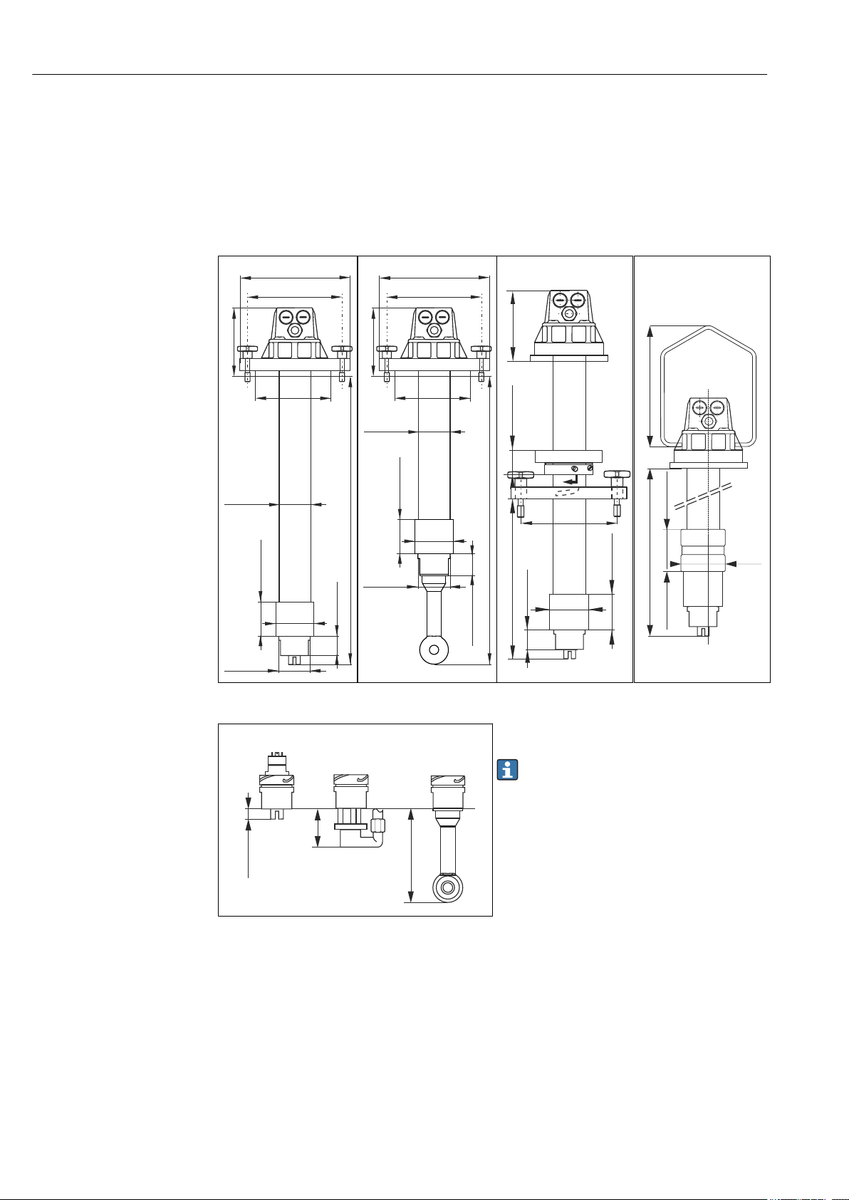
4.1.1 Dimensions
1 CLA111-A/C with
CLS21D/21
8 Endress+Hauser
5 Length below the sensor holder
* PEEK version
2 CLA111-A/C with
CLS50D/50
A0007462
3
CLA111-B
All dimensions in mm (inch)
* Illustrations with CLS21D/21
Immersion length is the same when CLS50D/50 is
installed. The length of the assembly pipe changes
accordingly → 2.
*
4
CLA111-D
*
Page 9

Dipfit CLA111 Installation
Ø18(0.71)
24(0.94)
133(5.24)
180(7.09)
220(8.66)
a
a
194(7.64)
133(5.24)
180(7.09)
220(8.66)
Ø18(0.71)
24(0.94)
A0007041
6 Pressurized flange DN 100
for CLA111-C
7 Flange DN 100 for
CLA111-A/B
A0007046
All dimensions in mm (inch) a = bore holes for cross formed screws
Endress+Hauser 9
Page 10

Installation Dipfit CLA111
5
4.1.2 Measuring system
8 Example of a measuring system
1 Assembly holder CYH112 (with chain) 4 Sensor CLS50D
2 Sensorkabel CYK10 (CLS21D) bzw. Festkabel
(CLS50D)
3 Transmitter CM442 with weather protection
cover
5 Sensor CLS21D
6 Assembly CLA111-D (with suspension bracket)
A0026966
10 Endress+Hauser
Page 11

Dipfit CLA111 Installation
1 2
3
4
5
6
7
8
9
10
11
12
1 2
3
6
4
5
6
4.2 Installing the assembly
4.2.1 Versions with a flange
A0007455
9 Version A and C with flange DN 100
1 Phillips screw (x 4)
2 Assembly head
3 Dummy plug
4 Quick connect coupling for Chemoclean cleaning
5 Connection pipe with pipe unions for Chemoclean
cleaning
6 Sensor holder
7 Spray head for Chemoclean cleaning
8 Sensor holder with fixing bolts for Chemoclean
spray head CLR30
9 Assembly pipe
10 Flange DN 100 , A: standard , C: pressurized flange
11 Cross formed screws (not for pressurized version)
12 Gland Pg 13.5
10 Version B with adjustable flange DN 100
1 Adjustable flange adapter (2 half-shells)
2 O-ring for tolerance compensation
3 Tensioning screws (x 2)
4 Flange DN 100
5 Sensor holder
6 Bayonet lock
Installing the assembly with flange DN 100 (version A and C)
Use the drawing as a guide (→ 9).
‣
A0007459
Endress+Hauser 11
Page 12

Installation Dipfit CLA111
1 2
3
4
Installing the assembly with adjustable flange DN 100 (version B)
1
Phillips screws
2
Half-shells
3
Assembly pipe
4
"Final position" marker
A0007049
11 Adjustable flange adapter
1. Mount the flange DN 100 on the frame.
2. Fit the half-shells (→ 11, item 2) of the adapter in the desired position on the
pipe.
3. Tighten the half-shells with the two Phillips screws (item 1).
4. Insert the O-ring into the O-ring groove (adjustable flange adapter on outside).
5. Insert the assembly into the ready-mounted flange DN 100.
6. Holding the assembly by the assembly head, screw the assembly clockwise into the
bayonet lock as far as the "final position" marker (item 4).
Removing the assembly
1. Leave the mounted flange DN 100 on the frame.
2. Holding the assembly by the assembly head, screw the assembly counter-clockwise
out of the bayonet lock and remove the assembly from the medium.
12 Endress+Hauser
Page 13

Dipfit CLA111 Installation
1 2
3
4
5
6
7
8
9
4.2.2 Version with suspension bracket
1
Suspension bracket
2
Dummy plug Pg 16
3
Assembly head
4
Weight (half-shells)
5
Sleeve
6
Sensor CLS50
7
Sensor holder
8
Cable clamp for fixing the half-shells
9
Gland Pg 13.5
A0007460
12 Version with suspension bracket
Installing the assembly in the measuring point
1. You can install the assembly on the basin.
To do so, suspend the assembly from the chain retainer CYH112.
The mounting chain enables a flexible immersion depth.
2. The weight (item 4) is required to stabilize the assembly.
Push the weight down as far as the sleeve (item 5).
3. Then fix the cable clamp (item 8).
Endress+Hauser 13
Page 14

Electrical connection Dipfit CLA111
4.3 Installing the sensor
4.3.1 CLS21D and CLS21
1. Unscrew the sensor holder from the bayonet lock.
2. Push the O-ring over the threaded shaft of the sensor.
3. Screw the sensor into the sensor holder from above.
Connect the sensor cable (→ 15).
4. Screw the sensor holder into the bayonet lock.
4.3.2 CLS50D and CLS50
1. Unscrew the sensor holder from the bayonet lock.
2. Push the O-ring over the threaded shaft of the sensor.
3. Guide the sensor cable through the sensor holder and the assembly pipe and screw
the sensor into the sensor holder from below.
4. Screw the sensor holder into the bayonet lock.
4.4 Post-installation check
1. After mounting, check all the connections to ensure they are secure and leak-tight.
2. Check the hoses for damage.
5 Electrical connection
WARNING
L
Device is live
Incorrect connection may result in injury or death.
The electrical connection may be performed only by an electrical technician.
‣
The electrical technician must have read and understood these Operating Instructions
‣
and must follow the instructions contained therein.
Prior to commencing connection work, ensure that no voltage is present on any cable.
‣
14 Endress+Hauser
Page 15

Dipfit CLA111 Electrical connection
1
2
3
4
5
6
1
2
3 4
5
6
7
BK
BU
YE
BN
GN
WH
YE
1
2
3
5.1 Connecting the sensor
Connecting the CLS21D, CLS50D or CLS50
The sensor can be connected to a variety of transmitters.
Pay attention to the connection instructions, e.g. for the terminal assignment, in the
Operating Instructions of the transmitter used.
1. Guide the sensor cable from the sensor through the sensor holder and assembly pipe
to the assembly head and through the Pg 13.5 cable gland to the outside.
2. Connect the sensor cable directly to the transmitter.
Connecting the CLS21
A special measuring cable is included with the assembly delivery to connect the CLS21
sensor. Connect this cable to the terminals in the assembly head.
A0007457
14 Terminals
1 Measuring cable CYK71 (to transmitter)
2 Terminals
3 Measuring cable (to sensor)
A0007456
13 Measuring cable connection for CLS21
1 Assembly head cover
2 Terminals
3 Assembly head
4 Measuring cable connector
5 Sensor CLS21
6 Sensor holder
1. Unscrew the cover (→ 13, item 1) of the assembly head (item 3).
2. Push the measuring cable supplied through the assembly pipe from below.
3. Connect the cable to the terminals in the assembly head (→ 14, item 2 and 3).
4. Attach the connector (→ 13, item 4) of the cable to the sensor plug-in head (item
5).
5. Screw the sensor holder (item 6) into the bayonet lock of the assembly pipe.
Endress+Hauser 15
Page 16

Electrical connection Dipfit CLA111
6. Mount a Pg 13.5 cable gland in the assembly head cover.
7. Guide the measuring cable CYK71 (not included in the delivery for the assembly)
through the Pg gland.
8. Connect the cable to the terminals (→ 14, item 1 and 2).
9. Screw the assembly head cover onto the assembly head.
5.2 Post-connection check
Device condition and specifications Notes
Are the outside of the sensor, assembly, cable undamaged? Visual inspection
Electrical connection Notes
Are the installed cables strain-relieved and not twisted?
Is a sufficient length of the cable cores stripped, and is it
positioned in the terminal correctly?
Are all the screws terminals properly tightened? Tighten
Are all cable entries mounted, tightened and leak-tight? For lateral cable entries, make sure the
Are all cable entries installed downwards or mounted laterally?
Check the fit (by pulling gently)
cables loop downwards to allow water to
drip off
16 Endress+Hauser
Page 17

Dipfit CLA111 Maintenance
6 Maintenance
WARNING
L
Risk of injury if medium escapes
Before every maintenance task make sure that the process pipe or container is empty
‣
and rinsed.
Take all the necessary precautions in time to ensure the operational safety and reliability
of the entire measuring system.
NOTICE
Effects on process and process control
When carrying out any work on the system, take into account possible repercussions
‣
for process control or the process itself.
For your own safety, only use genuine accessories. With genuine parts, the function,
‣
accuracy and reliability are also ensured after maintenance work.
6.1 Servicing the assembly
The assembly must be serviced at regular intervals. The frequency and type of servicing
depend on the medium.
1. Remove buildup on the assembly from time to time.
2. Keep O-rings and sealing surfaces clean.
3. Replace damaged O-rings.
Versehen Sie trockene O-Ringe mit einem dünnen Fettfilm (z.B. Syntheso Glep).
4. Replace damaged parts of the assembly.
Most common types of fouling and suitable cleaning agents
Fouling Suitable cleaning agent
Greases and oils Agents containing surfactants (alkaline agents) or water-soluble
organic solvents (halogen-free, e.g. ethanol)
Limescale deposits, metal hydroxide
buildup, lyophobic biological buildup
Sulfide deposits Mixture of 3% hydrochloric acid and thiocarbamide (commercially
Protein buildup Mixture of 3% hydrochloric acid and pepsin (commercially available)
Fibers, suspended substances Pressurized water, possibly surface-active agents
Light biological buildup Pressurized water
WARNING
L
Solvents containing halogens and acetone
Gesundheitsgefährdung durch Einatmen, können Krebs verursachen (z.B. Chloroform) und
Kunststoffteile der Armatur oder Sensors zerstören (Aceton).
Never use acetone or any solvents containing halogens.
‣
Approx. 3% hydrochloric acid
available)
6.2 Cleaning the sensor
You must clean the sensor:
• Before every calibration
• Regularly during operation
• Before returning it for repairs
Endress+Hauser 17
Page 18

Repairs Dipfit CLA111
1 2
3
4
You can remove the sensor and clean it manually. Alternatively you can use the
Chemoclean automatic spray cleaning system for cyclic sensor cleaning. The complete
cleaning system includes:
• Spray head CLR30
• Cleaning injector CYR10
• Cleaning control, e.g. internally via transmitter Liquisys CLM223/253 with a Plus
Package.
7 Repairs
7.1 Spare parts
A0007491
15 Spare parts
7.2 Return
Item
No.
1 Conductivity sensor cable; 3 m with straight connector for
2 O-ring; ID = 28.17; W = 3.53; OD = 35.23; EPDM 50051753
3 PP sensor holder G¾ (without accessories) for CLS50D/
3 Kit for PP sensor holder G1
4 O-ring; ID = 53.57; W = 3.53; OD = 60.63; VITON 50009289
Description and contents Order No.
50015632
CLS21
51500640
CLS50 installation
50074080
• O-ring; ID = 53.57; W = 3.53; OD = 60.63; VITON
• O-ring; ID = 28.17; W = 3.53; OD = 35.23; EPDM
• Cable; 3 m with straight connector for CLS21
The product must be returned if repairs or a factory calibration are required, or if the
wrong product was ordered or delivered. As an ISO-certified company and also due to legal
regulations, Endress+Hauser is obliged to follow certain procedures when handling any
returned products that have been in contact with medium.
To ensure swift, safe and professional device returns, please read the return procedures
and conditions at www.endress.com/support/return-material.
7.3 Disposal
The device contains electronic components and must therefore be disposed of in
accordance with regulations on the disposal of electronic waste.
18 Endress+Hauser
Observe the local regulations.
Page 19

Dipfit CLA111 Accessories
300 (11.8)
300 (11.8)
165 (6.50)
52.5 (2.07)
30 (1.18)
40 (1.57)
10 (0.39) 10 (0.39)
10 (0.39)
30 (1.18)
2 x M10
144 (5.67)
4 x Ø9 (0.35)
150 (5.91)
35 (1.38)
150 (5.91)
10 (0.39)
10 (0.39)
7.5 (0.30)
15 (0.59)
8 Accessories
The following are the most important accessories available at the time this
documentation was issued. For accessories not listed here, please contact your service
or sales office.
8.1 Installation accessories
Flexdip CYH112
• Modular holder system for sensors and assemblies in open basins, channels and tanks
• For Flexdip CYA112 water and wastewater assemblies
• Can be affixed anywhere: on the ground, on the capstone, on the wall or directly onto
railings.
• Stainless steel version
• Product Configurator on the product page: www.endress.com/cyh112
Technical Information TI00430C
Mounting frame
For CPA111, CPA510, CPA530 and CLA111
• Material: stainless steel 1.4301 (AISI 304)
• Order number: 50066561
A0007060
16 Mounting frame in mm (inch)
Adjustable flange adapter DN 100
• For CPA111 and CLA111 for variable immersion depths
• Order number: 50070514
Flange DN 100, unpressurized
• For CPA111 and CLA111 suitable for adjustable flange adapter
• Order number: 50066632
8.2 Sensors
Condumax CLS21D/ CLS21
• Two-electrode sensor in plug-in head version and fixed cable version
Endress+Hauser 19
• Product Configurator on the product page: www.endress.com/CLS21d or
www.endress.com/CLS21
Technical Information TI00085C
Page 20

Accessories Dipfit CLA111
48(1.89)
Ø10(0.39)
Indumax CLS50D/ CLS50
• High-durability inductive conductivity sensor
• For standard and hazardous area applications
• With Memosens technology (CLS50D)
• Product Configurator on the product page: www.endress.com/cls50d or
www.endress.com/cls50
Technical Information TI00182C
8.3 Extension cable
Memosens data cable CYK11
• Extension cable for digital sensors with Memosens protocol
• Product Configurator on the product page: www.endress.com/cyk11
Technical Information TI00118C
Measuring cable CYK71
• Unterminated cable for connecting analog sensors and for extending sensor cables
• Sold by the meter, order numbers:
– Non-Ex version, black: 50085333
– Ex-version, blue: 50085673
8.4 Chemoclean
Chemoclean CLR30
Automatic spray cleaning system for cleaning the sensors CLS21/CLS21D
Order according to product structure
Materials in contact with the medium
Spray head PP-GF20
O-rings EPDM / VITON
Operating data
Process pressure Max. 4 bar (58 psi) absolute, at 20 °C
Process temperature Max. 80 °C (176 °F) at ambient
Cleaner pressure 4 to 6 bar (58 to 87 psi) absolute, at
(68 °F)
pressure
20 °C (68 °F)
20 Endress+Hauser
Page 21

Dipfit CLA111 Technical data
9 Technical data
9.1 Environment
Ambient temperature range
-10 to +80 °C (+10 to +180 °F)
9.2 Process
Process temperature -10 to +80 °C (+10 to +180 °F)
Process pressure
CLA111-A/B/D Unpressurized
CLA111-C Max. 5 bar (72 psi) abs. at 20 °C (68 °F),
9.3 Mechanical construction
Dimensions → 8
Weight Approx. 4.0 kg (8.8 lbs)
Materials
Sensor holder PP-GF 20
Immersion tube PP
O-ring VITON
Only version CLA111-D:
Half-shells Cast iron, PVC-coated
Cable clamp Stainless steel 1.4401 (AISI 316)
unpressurized up to 80 °C (176 °F)
Cable entries 1 x Pg 13.5 and 2 x Pg 16
Sensors suitable for use CLS21D, CLS21, CLS50D, CLS50
Immersion depth Standard 1000 mm (39.4 inch), 2000 mm (78.8 inch)
Other length 500 to 3000 mm (19.7 to 118 inch)
Process connections CLA111-A Flange DN 100, additionally with captive cross
formed screws
CLA111-B Adjustable flange DN 100
CLA111-C Pressurized flange DN 100
CLA111-D Stainless steel suspension bracket (1.4571 (AISI 316
Ti))
Endress+Hauser 21
Page 22

Index Dipfit CLA111
Index
A
Ambient temperature range ................... 21
Assembly
Installation ............................. 11
Servicing ............................... 17
C
Check
Connection ..............................16
Installation ............................. 14
Chemoclean ............................... 20
D
Designated use .............................. 4
Disposal .................................. 18
E
Electrical connection ......................... 14
I
Incoming acceptance ......................... 6
Installation
Check ..................................14
Installation conditions ...................... 8
Installing the assembly ..................... 11
Sensor ................................. 14
Installation conditions
Dimensions .............................. 8
Measuring system ........................ 10
T
Technical data
Environment ............................ 21
Mechanical construction ....................21
Process ................................ 21
U
Use .......................................4
M
Maintenance ...............................17
N
Nameplate ................................. 6
P
Process pressure ............................ 21
Process temperature ......................... 21
Product identification ......................... 6
R
Repairs ................................... 18
Return ................................... 18
S
Safety information ........................... 3
Safety instructions ............................4
Scope of delivery ............................. 7
Sensor
Accessories ............................. 19
Cleaning ............................... 17
Connecting ..............................15
Installing ............................... 14
Spare parts ................................ 18
Suspension bracket .......................... 13
Symbols ................................... 3
22 Endress+Hauser
Page 23

Page 24

*71293522*
71293522
www.addresses.endress.com
 Loading...