

Products Solutions Services
Operating Instructions
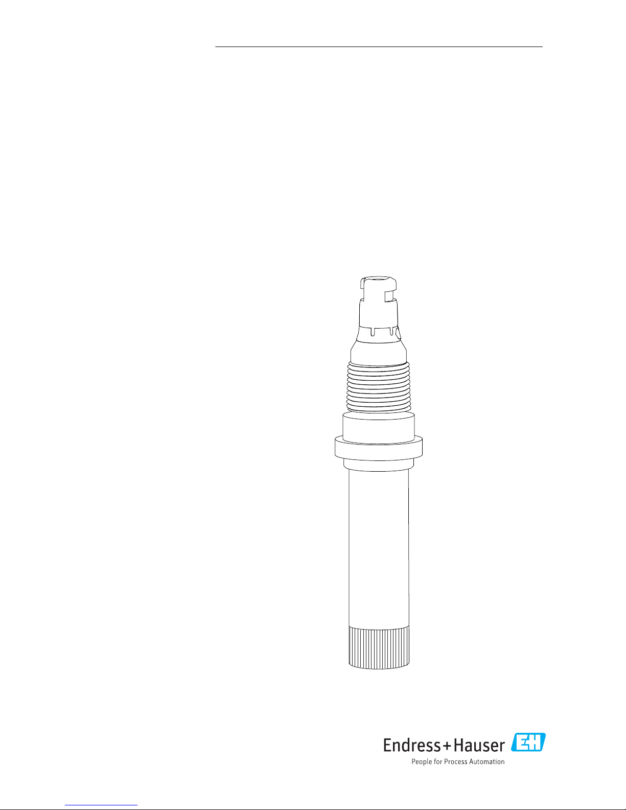
Chloromax CCS142D
Digital sensor with Memosens technology for
determining free chlorine
BA00419C/07/EN/15.17
71378188
AUTHORIZED DISTRIBUTOR:
InstrumentsAndControl.com
Houston, Texas USA
sales@InstrumentsAndControl.com
281-609-7170


Chloromax CCS142D Table of contents
Endress+Hauser 3
Table of contents
1 Document information ......... 4
1.1 Warnings ........................... 4
1.2 Symbols used ........................ 4
2 Basic safety instructions ....... 6
2.1 Requirements for the personnel ........ 6
2.2 Designated use ...................... 6
2.3 Occupational safety .................. 6
2.4 Operational safety ................... 7
2.5 Product safety ....................... 7
3 Product description ............. 8
3.1 Product design ....................... 8
4 Incoming acceptance and
product identification ......... 13
4.1 Incoming acceptance ................ 13
4.2 Product identification ................ 13
5 Installation .................... 16
5.1 Installation conditions ............... 16
5.2 Mounting the sensor ................ 18
5.3 Post-installation check ............... 19
6 Electrical connection .......... 20
6.1 Connecting the sensor ............... 20
6.2 Ensuring the degree of protection ..... 20
6.3 Post-connection check ............... 20
7 Commissioning ................ 22
7.1 Function check ..................... 22
7.2 Sensor polarization .................. 22
7.3 Calibrating the sensor ............... 22
8 Diagnostics and
troubleshooting ............... 24
9 Maintenance .................. 26
9.1 Maintenance schedule ............... 26
9.2 Maintenance tasks .................. 26
10 Repair .......................... 31
10.1 Spare parts ........................ 31
10.2 Return ............................ 31
10.3 Disposal ........................... 31
11 Accessories .................... 32
11.1 Device-specific accessories ............ 32
12 Technical data ................. 33
13 Installation and operation in
hazardous environment Class
I Div. 2 .......................... 36
Index ................................. 38
Document information Chloromax CCS142D
4 Endress+Hauser
1 Document information
1.1 Warnings
Structure of information Meaning
L
DANGER
Causes (/consequences)
If necessary, Consequences of noncompliance (if applicable)
‣
Corrective action
This symbol alerts you to a dangerous situation.
Failure to avoid the dangerous situation will result in a fatal or serious injury.
L
WARNING
Causes (/consequences)
If necessary, Consequences of noncompliance (if applicable)
‣
Corrective action
This symbol alerts you to a dangerous situation.
Failure to avoid the dangerous situation can result in a fatal or serious injury.
L
CAUTION
Causes (/consequences)
If necessary, Consequences of noncompliance (if applicable)
‣
Corrective action
This symbol alerts you to a dangerous situation.
Failure to avoid this situation can result in minor or more serious injuries.
NOTICE
Cause/situation
If necessary, Consequences of noncompliance (if applicable)
‣
Action/note
This symbol alerts you to situations which may result in damage to property.
1.2 Symbols used
Symbol Meaning
Additional information, tips
Permitted or recommended
Not permitted or not recommended
Reference to device documentation
Reference to page
Reference to graphic
Result of a step

Chloromax CCS142D Document information
Endress+Hauser 5
1.2.1 Symbols on the device
Symbol Meaning
Reference to device documentation

Basic safety instructions Chloromax CCS142D
6 Endress+Hauser
2 Basic safety instructions
2.1 Requirements for the personnel
Installation, commissioning, operation and maintenance of the measuring system may be
carried out only by specially trained technical personnel.
‣
The technical personnel must be authorized by the plant operator to carry out the specified
activities.
‣
The electrical connection may be performed only by an electrical technician.
‣
The technical personnel must have read and understood these Operating Instructions and
must follow the instructions contained therein.
‣
Measuring point faults may be repaired only by authorized and specially trained personnel.
Repairs not described in the Operating Instructions provided must be carried out only
directly at the manufacturer's site or by the service organization.
2.2 Designated use
Drinking water, process water and bathing water must be disinfected through the addition of
appropriate disinfectants such as chlorine gas or inorganic chlorine compounds. The dosing
quantity involved must be adapted to continuously fluctuating operating conditions. Too low
concentrations in the water could jeopardize the effectiveness of the disinfection process. Too
high concentrations can lead to signs of corrosion and have an adverse effect on taste, while
also generating unnecessary costs.
The sensor was specifically developed for this application and is designed for continuous
measurement of free chlorine in water. In conjunction with measuring and control equipment,
it allows optimum control of the disinfection process.
Use of the device for any purpose other than that described, poses a threat to the safety of
people and of the entire measuring system and is therefore not permitted.
The manufacturer is not liable for damage caused by improper or non-designated use.
2.2.1
Hazardous environment in accordance with cETLus NI Cl. I, Div. 2
1)
‣
Please note the control drawing and the specified application conditions in the appendix of
these Operating Instructions and follow the instructions.
2.3 Occupational safety
As the user, you are responsible for complying with the following safety conditions:
• Installation guidelines
• Local standards and regulations
1) Only if connected to CM444R-EA* or CM448R-EA*

Chloromax CCS142D Basic safety instructions
Endress+Hauser 7
Electromagnetic compatibility
• The product has been tested for electromagnetic compatibility in accordance with the
applicable European standards for industrial applications.
• The electromagnetic compatibility indicated applies only to a product that has been
connected in accordance with these Operating Instructions.
2.4 Operational safety
Before commissioning the entire measuring point:
1. Verify that all connections are correct.
2. Ensure that electrical cables and hose connections are undamaged.
3. Do not operate damaged products, and protect them against unintentional operation.
4. Label damaged products as defective.
During operation:
‣
If faults cannot be rectified:
products must be taken out of service and protected against unintentional operation.
2.4.1 Special instructions
‣
Do not operate the sensors under process conditions where it is expected that osmotic
conditions will cause electrolyte components to pass through the membrane and into the
process.
Use of the sensor for its intended purpose in liquids with a conductivity of at least 10 nS/cm
can be classified as electrostatically safe.
2.5 Product safety
The product is designed to meet state-of-the-art safety requirements, has been tested, and
left the factory in a condition in which it is safe to operate. The relevant regulations and
European standards have been observed.
Product description Chloromax CCS142D
8 Endress+Hauser
3 Product description
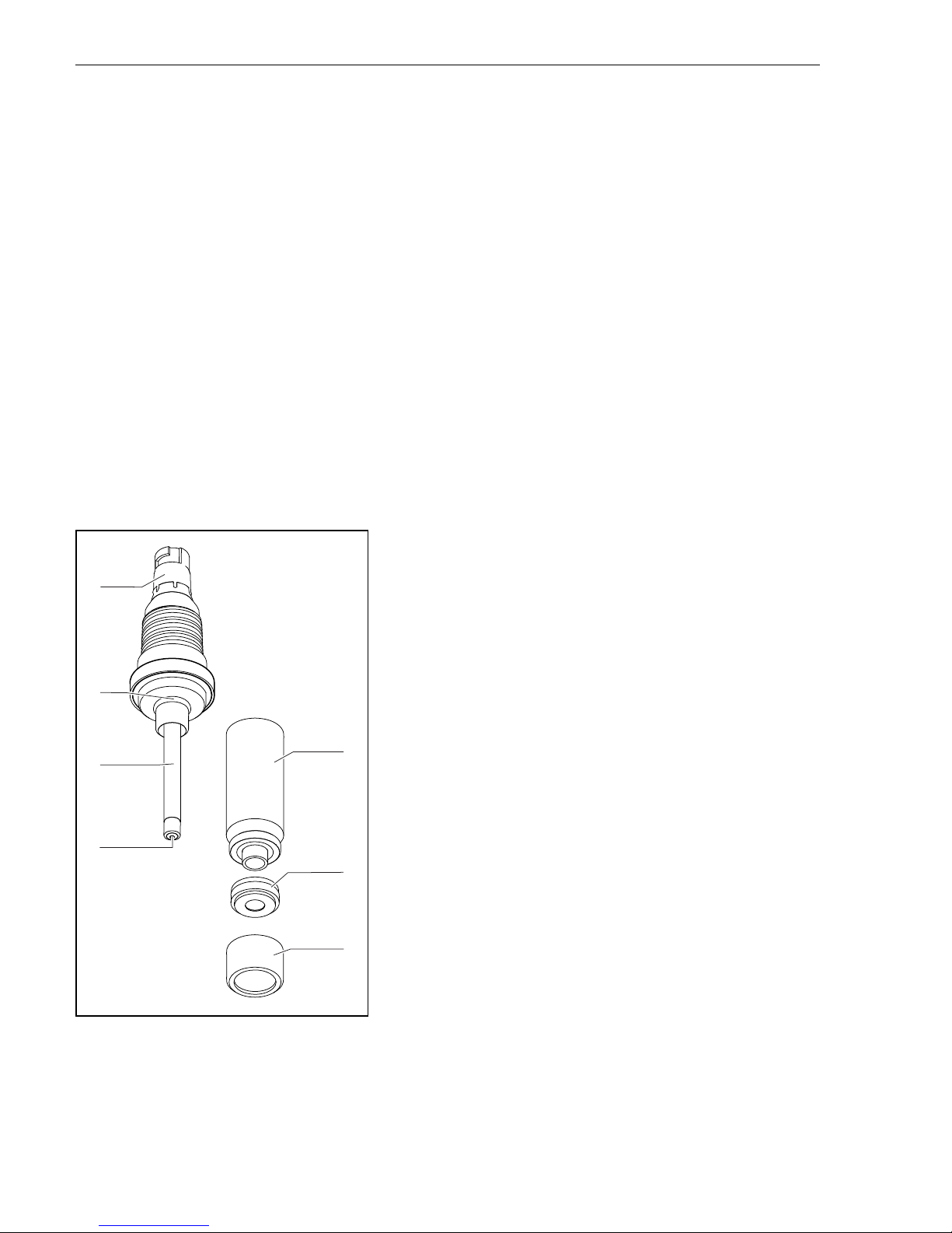
3.1 Product design
The sensor consists of the following function units:
• Measuring chamber
– To protect the anode or cathode from the medium
– With a large volume of electrolyte for a long service life in combination with the large
anode and the small cathode
• Sensor shaft with
– Large anode
– Cathode embedded in plastic
– Temperature sensor
• Membrane cap with
– Robust PTFE membrane
– Special support grid between cathode and membrane for a specified and constant
electrolyte film and thus a relatively constant indication even at varying pressures and
flows
3
4
5
6
7
1
2
A0026479
1 Sensor structure
1 Memosens plug-in head
2 O-ring
3 Large anode, silver/silver chloride
4 Gold cathode
5 Measuring chamber
6 Membrane cap with dirt-repellent membrane
7 Screw cap for securing the membrane cap
3.1.1 Measuring principle
Free chlorine is determined as hypochlorous acid according to the amperometric measuring
principle.

Chloromax CCS142D Product description
Endress+Hauser 9
The hypochlorous acid (HOCl) contained in the medium diffuses through the sensor
membrane and is reduced to chloride ions (Cl-) at the gold cathode. At the silver anode, silver
is oxidized to silver chloride. Electron donation at the gold cathode and electron acceptance at
the silver anode causes a current to flow which is in proportion to the concentration of free
chlorine in the medium at constant conditions.
The concentration of hypochlorous acid depends on the pH value. This dependency can be
compensated for by measuring the pH value in the flow assembly.
The transmitter uses the current signal to calculate the measured variable for concentration in
mg/l.
3.1.2 Effects on the measuring signal
pH value
pH-dependency
Molecular chlorine (Cl2) is present at pH values < 4. Consequently, hypochlorous acid (HOCl)
and hypochlorite (OCl– remain within the range of pH 4 to 11 as components of free chlorine.
As hypochlorous acid splits up (dissociates) with an increasing pH value to form hypochlorite
ions (OCl–) and hydrogen ions (H+), the amounts of the individual components of free
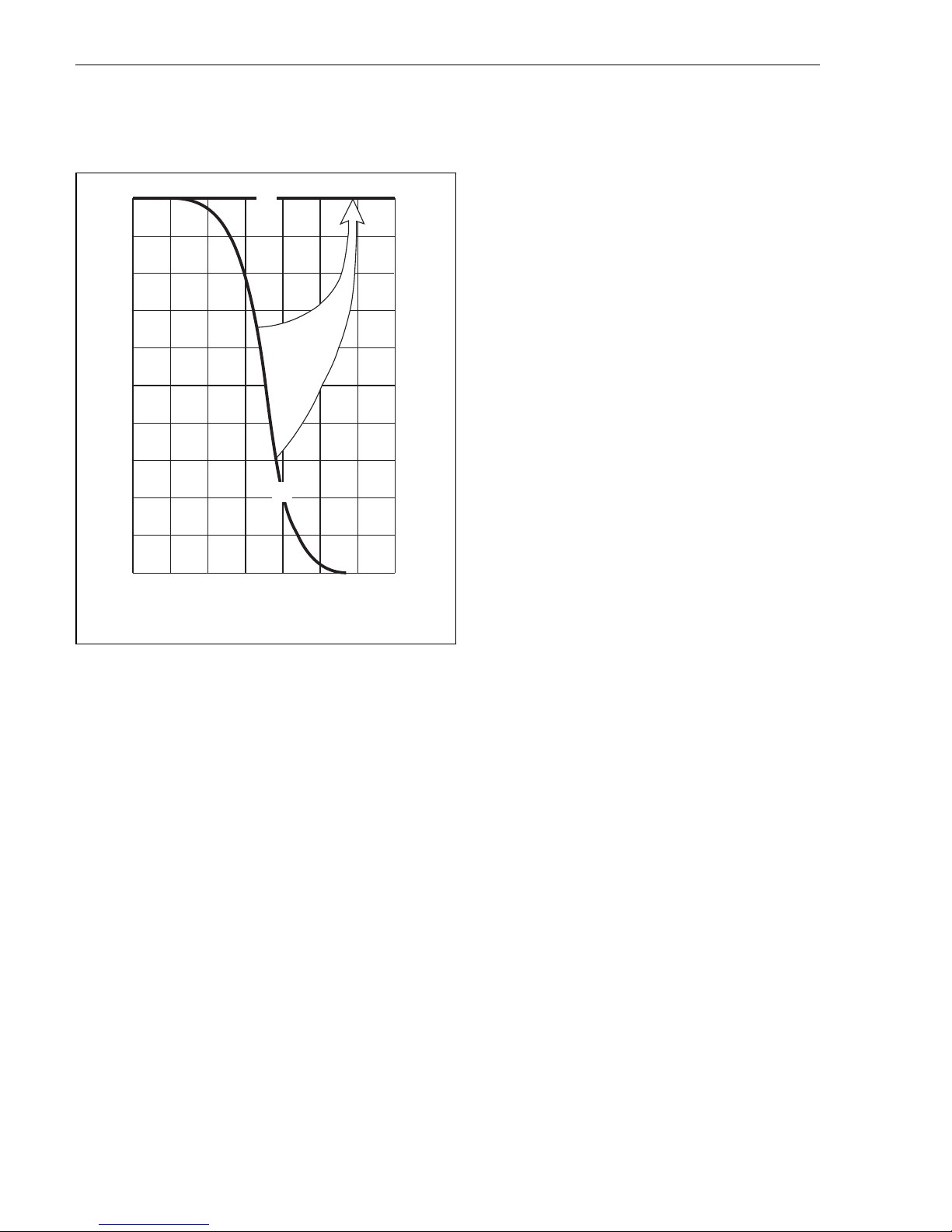
Product description Chloromax CCS142D
10 Endress+Hauser
effective chlorine change with the pH value. For example, if the proportion of hypochlorous
acid is 97 % at pH 6, it drops to approx. 3 % at pH 9.
%
100
80
60
40
20
0
4
5 6 7 8 9 10 11
100
%
80
60
40
20
0
A
pH
OCl
-
HOCl
C
B
A0002017
2 Principle of pH compensation
A Measured value with pH compensation
B Measured value without pH compensation
C pH compensation
For amperometric measurement using the CCS142D chlorine sensor, only the amount of
hypochlorous acid is selectively measured. This works as a powerful disinfectant in a watery
solution. In contrast to this, hypochlorite is an extremely weak disinfectant. Therefore, when
used as a disinfectant at higher pH values, the effectiveness of chlorine is limited. As
hypochlorite ions cannot permeate the sensor membrane, the sensors do not record this
value.
pH compensation of chlorine sensor signal
To calibrate and verify the chlorine measuring system, a colorimetric reference measurement
must be carried out using the DPD method. Free chlorine reacts with diethyl-pphenylendiamine to form a red dye. The intensity of the red color increases proportionally to
the chlorine content. With the DPD method, the sample is buffered to a pH value of approx.
6.3. Therefore, the pH value of the sample is not included in the DPD measurement. Due to
the buffer function in the DPD method, all components of free effective chlorine are recorded
and thus the total free chlorine is measured.
If pH compensation is switched on in the transmitter, the sum of hypochlorous acid (HOCl)
and hypochlorite corresponding to the DPD measurement is calculated from the chlorine

Chloromax CCS142D Product description
Endress+Hauser 11
sensor's measuring signal that corresponds to hypochlorous acid (HOCl) and by taking into
account the pH value in the range of pH 4 to 9. For this calculation, the curve is stored in the
transmitter.
When free chlorine is measured with pH compensation switched on, always perform
calibration in pH-compensated mode.
When you use pH compensation, the measured chlorine value that is displayed and applied to
the device output corresponds to the DPD measured value even if the pH values fluctuate. If
you do not use pH compensation, the measured chlorine value corresponds to the DPD
measurement only if the pH value remains unchanged compared with the calibration.
Without pH compensation, the chlorine measuring system must be recalibrated when the pH
value changes.
Accuracy of pH compensation
The accuracy of the pH-compensated measured chlorine value is derived from the sum of
several individual deviations (chlorine, pH, temperature, DPD measurement etc.).
High levels of hypochlorous acid (HOCl) during chlorine calibration have a positive effect on
accuracy, whereas low levels of hypochlorous acid have a negative effect. The inaccuracy of
the pH-compensated measured chlorine value increases the greater the pH difference
between measuring mode and chlorine calibration or the more inaccurate the underlying
individual measured values are.
Calibration taking into account the pH value
The reference measurement (DPD method, photometer) determines the total free chlorine by
buffering to pH 6.3. In contrast to this, amperometric measurement determines only the HOCl
component.
During operation, pH compensation is effective up to a pH value of 9. However, there is hardly
any HOCl left at this pH value, and the measured current is very low. At this point, pH
compensation has the effect of increasing the measured HOCl value to the actual value of the
free chlorine. Calibration of the complete measuring system makes sense only if the medium
has a pH value up to 8 or 8.2.
Sensor pH value HOCl content Uncompensated value Compensated value
CCS142D-G 8.2 15 % 12 nA 80 nA
CCS142D-A 8.0 20 % 4 nA 20 nA
Above these pH values, the total error of the measuring system is unacceptably high.
Flow
The minimum flow velocity of the membrane-covered sensor is 15 cm/s (0.5 ft/s).
When using the CCA250 flow assembly, this corresponds to a flow rate of 30 l/h (8 gal/h)
(upper edge of float at level of red bar mark).
At higher flow rates, the measuring signal is virtually flow-independent. However, if the flow
rate falls below the specified value, the measuring signal depends on the flow.

Product description Chloromax CCS142D
12 Endress+Hauser
The installation of an INS proximity switch in the assembly enables reliable detection of this
prohibited operating status, thus triggering an alarm or causing the dosing process to be
switched off if necessary.
Temperature
Changes in the temperature of the medium affect the measured value:
• Increases in temperature result in a higher measured value (approx. 4 % per K)
• Decreases in temperature result in a lower measured value
Use of the sensor in conjunction with the Liquiline enables automatic temperature
compensation (ATC). In this case, the temperature does not need to remain constant, and a
recalibration in the event of temperature changes is not required.
1. If automatic temperature compensation is disabled at the transmitter, maintain the
temperature following calibration at a constant level.
2. Otherwise, recalibrate the sensor.
 Loading...