

Endress+Hauser Ceraphant T PTC31, Ceraphant T PTP31, Ceraphant T PTP35 Operating Instructions Manual
Page 1
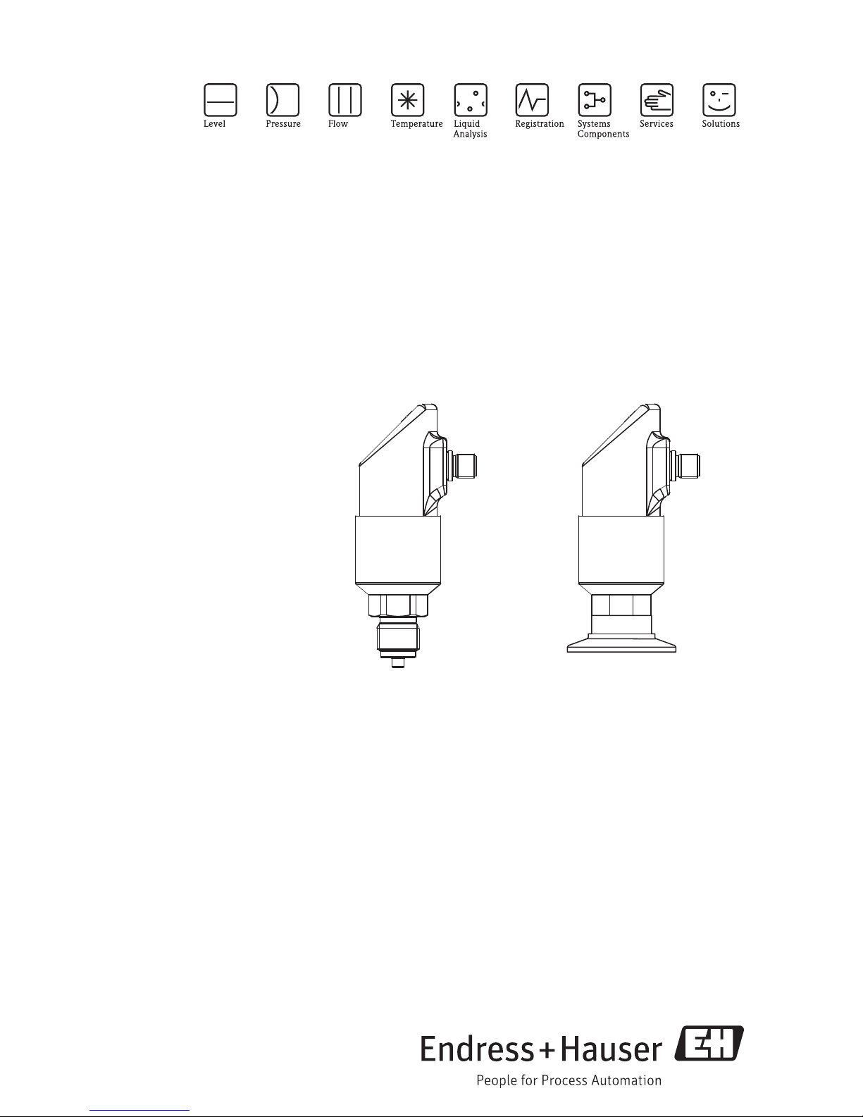
Operating Instructions
Ceraphant T PTC31, PTP31, PTP35
Process pressure measurement
AUTHORIZED DISTRIBUTOR:
InstrumentsAndControl.com
Houston, Texas USA
sales@InstrumentsAndControl.com
832-615-3588
Page 2
TAG No.: XXX000
Ser. No.: X000X000000
Order code 00X00-XXXX0XX0XXX
www.endress.com/deviceviewer Endress+Hauser Operations App
Serial number
Ceraphant T PTC31, PTP31, PTP35
A0023555
2 Endress+Hauser
Page 3

Ceraphant T PTC31, PTP31, PTP35 Table of contents
Table of contents
1 Safety instructions . . . . . . . . . . . . . . . . . . . . . . . . . . . . . . . . . . . . . . . . . . . . . . . . . 4
1.1 Designated use . . . . . . . . . . . . . . . . . . . . . . . . . . . . . . . . . . . . . . . . . . . . . . . . . . . . . . . . . . . . . . . . . . . . . . . . . . . 4
1.2 Installation, commissioning and operation . . . . . . . . . . . . . . . . . . . . . . . . . . . . . . . . . . . . . . . . . . . . . . . . . . . . . . . 4
1.3 Operational and process safety . . . . . . . . . . . . . . . . . . . . . . . . . . . . . . . . . . . . . . . . . . . . . . . . . . . . . . . . . . . . . . . 4
2 Identification . . . . . . . . . . . . . . . . . . . . . . . . . . . . . . . . . . . . . . . . . . . . . . . . . . . . . 5
2.1 Nameplate . . . . . . . . . . . . . . . . . . . . . . . . . . . . . . . . . . . . . . . . . . . . . . . . . . . . . . . . . . . . . . . . . . . . . . . . . . . . . . 5
2.2 CE mark, declaration of conformity . . . . . . . . . . . . . . . . . . . . . . . . . . . . . . . . . . . . . . . . . . . . . . . . . . . . . . . . . . . 6
2.3 Registered trademarks . . . . . . . . . . . . . . . . . . . . . . . . . . . . . . . . . . . . . . . . . . . . . . . . . . . . . . . . . . . . . . . . . . . . . 6
3 Installation . . . . . . . . . . . . . . . . . . . . . . . . . . . . . . . . . . . . . . . . . . . . . . . . . . . . . . 7
3.1 Incoming acceptance, storage . . . . . . . . . . . . . . . . . . . . . . . . . . . . . . . . . . . . . . . . . . . . . . . . . . . . . . . . . . . . . . . . 7
3.2 Installation instructions . . . . . . . . . . . . . . . . . . . . . . . . . . . . . . . . . . . . . . . . . . . . . . . . . . . . . . . . . . . . . . . . . . . . 7
3.3 Post-installation check . . . . . . . . . . . . . . . . . . . . . . . . . . . . . . . . . . . . . . . . . . . . . . . . . . . . . . . . . . . . . . . . . . . . . 8
4 Wiring. . . . . . . . . . . . . . . . . . . . . . . . . . . . . . . . . . . . . . . . . . . . . . . . . . . . . . . . . . 9
4.1 DC voltage version with M12 connector . . . . . . . . . . . . . . . . . . . . . . . . . . . . . . . . . . . . . . . . . . . . . . . . . . . . . . . 9
4.2 DC voltage version with valve connector . . . . . . . . . . . . . . . . . . . . . . . . . . . . . . . . . . . . . . . . . . . . . . . . . . . . . . . 9
4.3 DC voltage version with cable . . . . . . . . . . . . . . . . . . . . . . . . . . . . . . . . . . . . . . . . . . . . . . . . . . . . . . . . . . . . . . 10
4.4 Supply voltage . . . . . . . . . . . . . . . . . . . . . . . . . . . . . . . . . . . . . . . . . . . . . . . . . . . . . . . . . . . . . . . . . . . . . . . . . . 10
4.5 Current consumption . . . . . . . . . . . . . . . . . . . . . . . . . . . . . . . . . . . . . . . . . . . . . . . . . . . . . . . . . . . . . . . . . . . . . 10
4.6 Post-connection check . . . . . . . . . . . . . . . . . . . . . . . . . . . . . . . . . . . . . . . . . . . . . . . . . . . . . . . . . . . . . . . . . . . . 10
5 Operation . . . . . . . . . . . . . . . . . . . . . . . . . . . . . . . . . . . . . . . . . . . . . . . . . . . . . . 11
5.1 On-site operation . . . . . . . . . . . . . . . . . . . . . . . . . . . . . . . . . . . . . . . . . . . . . . . . . . . . . . . . . . . . . . . . . . . . . . . . 11
5.2 Operation with personal computer . . . . . . . . . . . . . . . . . . . . . . . . . . . . . . . . . . . . . . . . . . . . . . . . . . . . . . . . . . . 14
6 Commissioning . . . . . . . . . . . . . . . . . . . . . . . . . . . . . . . . . . . . . . . . . . . . . . . . . . 16
6.1 Function check . . . . . . . . . . . . . . . . . . . . . . . . . . . . . . . . . . . . . . . . . . . . . . . . . . . . . . . . . . . . . . . . . . . . . . . . . 16
6.2 Basic settings . . . . . . . . . . . . . . . . . . . . . . . . . . . . . . . . . . . . . . . . . . . . . . . . . . . . . . . . . . . . . . . . . . . . . . . . . . . 16
6.3 Output setting . . . . . . . . . . . . . . . . . . . . . . . . . . . . . . . . . . . . . . . . . . . . . . . . . . . . . . . . . . . . . . . . . . . . . . . . . . 17
6.4 Service function setting . . . . . . . . . . . . . . . . . . . . . . . . . . . . . . . . . . . . . . . . . . . . . . . . . . . . . . . . . . . . . . . . . . . 19
7 Maintenance . . . . . . . . . . . . . . . . . . . . . . . . . . . . . . . . . . . . . . . . . . . . . . . . . . . . 20
7.1 Exterior cleaning . . . . . . . . . . . . . . . . . . . . . . . . . . . . . . . . . . . . . . . . . . . . . . . . . . . . . . . . . . . . . . . . . . . . . . . . 20
8 Accessories . . . . . . . . . . . . . . . . . . . . . . . . . . . . . . . . . . . . . . . . . . . . . . . . . . . . . 21
8.1 Process connection . . . . . . . . . . . . . . . . . . . . . . . . . . . . . . . . . . . . . . . . . . . . . . . . . . . . . . . . . . . . . . . . . . . . . . . 21
8.2 Welding bosses . . . . . . . . . . . . . . . . . . . . . . . . . . . . . . . . . . . . . . . . . . . . . . . . . . . . . . . . . . . . . . . . . . . . . . . . . 25
8.3 Electrical connection . . . . . . . . . . . . . . . . . . . . . . . . . . . . . . . . . . . . . . . . . . . . . . . . . . . . . . . . . . . . . . . . . . . . . 26
8.4 ReadWin . . . . . . . . . . . . . . . . . . . . . . . . . . . . . . . . . . . . . . . . . . . . . . . . . . . . . . . . . . . . . . . . . . . . . . . . . . . . . . 27
9 Trouble-shooting . . . . . . . . . . . . . . . . . . . . . . . . . . . . . . . . . . . . . . . . . . . . . . . . . 28
9.1 Errors and warnings . . . . . . . . . . . . . . . . . . . . . . . . . . . . . . . . . . . . . . . . . . . . . . . . . . . . . . . . . . . . . . . . . . . . . 28
9.2 Repair . . . . . . . . . . . . . . . . . . . . . . . . . . . . . . . . . . . . . . . . . . . . . . . . . . . . . . . . . . . . . . . . . . . . . . . . . . . . . . . . 29
9.3 Return . . . . . . . . . . . . . . . . . . . . . . . . . . . . . . . . . . . . . . . . . . . . . . . . . . . . . . . . . . . . . . . . . . . . . . . . . . . . . . . . 29
9.4 Disposal . . . . . . . . . . . . . . . . . . . . . . . . . . . . . . . . . . . . . . . . . . . . . . . . . . . . . . . . . . . . . . . . . . . . . . . . . . . . . . . 29
9.5 Change status (release) . . . . . . . . . . . . . . . . . . . . . . . . . . . . . . . . . . . . . . . . . . . . . . . . . . . . . . . . . . . . . . . . . . . . 29
9.6 Change status - history . . . . . . . . . . . . . . . . . . . . . . . . . . . . . . . . . . . . . . . . . . . . . . . . . . . . . . . . . . . . . . . . . . 30
10 Technical data . . . . . . . . . . . . . . . . . . . . . . . . . . . . . . . . . . . . . . . . . . . . . . . . . . . 30
Index . . . . . . . . . . . . . . . 31
Endress+Hauser 3
Page 4

Safety instructions Ceraphant T PTC31, PTP31, PTP35
1 Safety instructions
1.1 Designated use
The Ceraphant T is a pressure switch for measuring and monitoring absolute and gauge
pressures. The device has been safely built with state-of-the-art technology and meets the
applicable requirements and EC Directives. It can, however, be a source of danger if used
incorrectly or for anything other than the designated use.
1.2 Installation, commissioning and operation
Installation, electrical connection, commissioning, operation and maintenance of the measuring
system must be carried out by trained, qualified specialists authorised to perform such work by
the facility's owner-operator. The specialist must have read and understood these Operating
Instructions and must follow the instructions they contain. The device may only be modified and
repair work carried out if this is explicitly permitted in the Operating Instructions. Damaged
devices which could be a source of danger may not be commissioned and must be labelled and
identified as defective.
1.3 Operational and process safety
Explosion-hazardous areas:
The Ceraphant T is not approved for use in Ex-areas.
Alternative monitoring measures have to be taken while configuring, testing or servicing the
device to ensure the operational and process safety.
Warning!
#
Only disassemble the device in pressurless condition!
4 Endress+Hauser
Page 5
Ceraphant T PTC31, PTP31, PTP35 Identification
1
2
3
4
5
9
10
10 10
8
6
7
11
12
13
Ceraphant T
Made in Germany D-79689 Maulburg
p:
TAG:
Mat:
Ser.-No.:
Rel.:
Order Code:
MWP:
U:
I out:
15
L–
L+
2
1
3
4
14
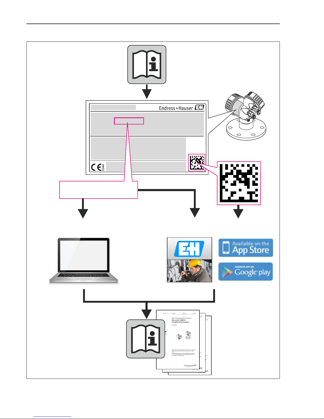
2 Identification
The following options are available for identification of the measuring device:
• Nameplate specifications
• Order code with breakdown of the device features on the delivery note
• Enter serial numbers from nameplates in W@M Device Viewer
(www.endress.com/deviceviewer): All information about the measuring device is displayed.
For an overview of the technical documentation provided, enter the serial number from the
nameplates in the W@M Device Viewer (www.endress.com/deviceviewer).
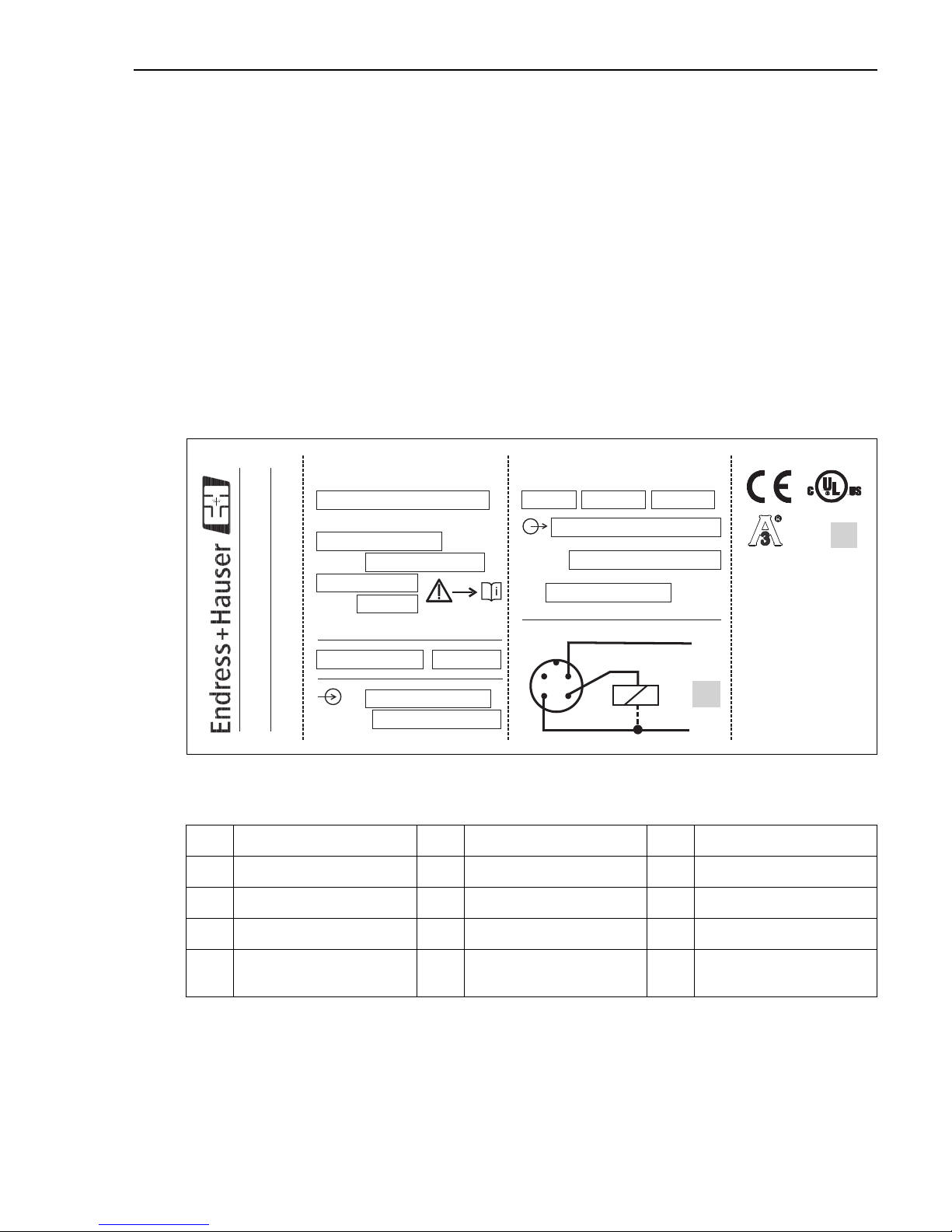
2.1 Nameplate
To identify your device, compare the complete order code and the version information on the
delivery papers with the data on the nameplate.
Fig. 1: Explanation of the nameplate - see table below
1 Order code 6 Degree of protection 11 Electronics
2 Serial number 7 Degree of protection 12 Current output
3 TAG number 8 Sensor range 13 Supply voltage
4 TAG number 9 Max. operating pressure 14 Connection diagram
5 Release number
(change status)
Note!
!
Endress+Hauser 5
• The release number indicates the change status of the device. A change in the last two figures
does not have any affect on the compatibility - see also Chap. 9.5.
10 Wetted materials 15 Approvals
P01-PTx3xxxx-18-xx-xx-xx-001
Page 6

Identification Ceraphant T PTC31, PTP31, PTP35
• The MWP (maximum working pressure) is specified on the nameplate. This value refers to a
reference temperature of +20 °C (68 °F) and may be applied to the device for an unlimited
time.
The test pressure (Over Pressure Limit OPL) corresponds to 1.5 times the MWP and may be
applied for a limited time only in order to avoid lasting damage.
2.2 CE mark, declaration of conformity
The device is designed to meet state-of-the-art safety requirements, has been tested and left the
factory in a condition in which it is safe to operate. The device complies with the applicable
standards and regulations as listed in the EC declaration of conformity and thus complies with
the statutory requirements of the EC Directives. Endress+Hauser confirms the successful testing
of the device by affixing to it the CE mark.
2.3 Registered trademarks
Ceraphire®
Registered trademark of Endress+Hauser GmbH+Co.KG, Maulburg, Germany
ReadWin®
Registered trademark of Endress+Hauser Wetzer GmbH+Co.KG, Nesselwang, Germany
LEXAN®
Registered trademark of General Electric Plastics B.V., Bergen op Zoom, Netherlands
THERMOPLAST
®
Registered trademark of Kraiburg TPE GmbH, Waldkraiburg, Germany
6 Endress+Hauser
Page 7
Ceraphant T PTC31, PTP31, PTP35 Installation
➀
➁
➂➂
➀
➁
➀
➁
3 Installation
3.1 Incoming acceptance, storage
• Incoming acceptance:
Check the packaging and the device for damage. Check that the goods delivered are complete
and nothing is missing.
•Storage:
Storage temperature -40...+85 °C (-40 to +185 °F)
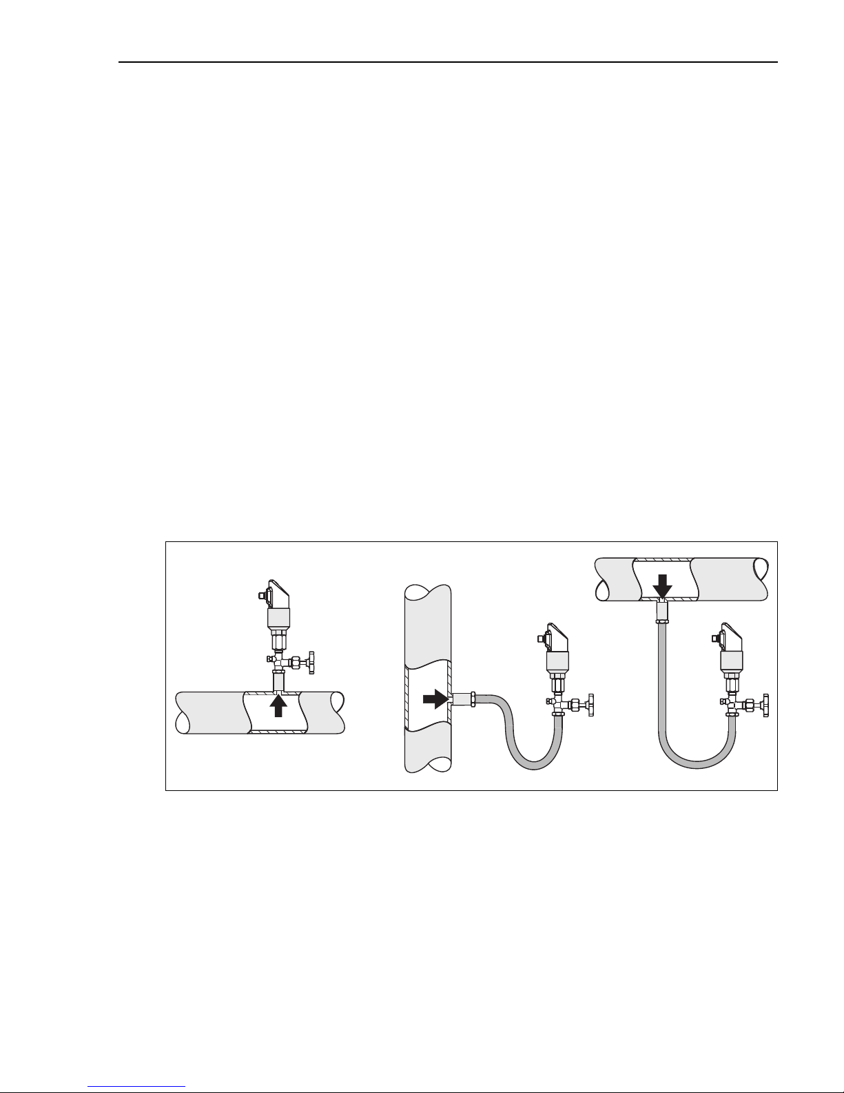
3.2 Installation instructions
For typical possibilities for installing the Ceraphant T - see the diagram below:
• Pressure measurement in gases (left)
Mount Ceraphant T with shut-off assembly above the sampling nozzle so that any condensate
can drain off into the process.
• Pressure measurement in steam (centre)
Mount Ceraphant T with U-pipe above the sampling nozzle. Fill the U-pipe with fill fluid
before commissioning.
• Pressure measurement in liquids (right)
Mount Ceraphant T below or at the same level as the sampling nozzle.
Fig. 2: Possibilities for installing to measure pressure in gases, steam and liquids.
➀ Ceraphant T
➁ Shut-off assembly
➂ U-pipe
Endress+Hauser 7
P01-PTx3xxxx-11-xx-xx-xx-001
Page 8

Installation Ceraphant T PTC31, PTP31, PTP35
3.2.1 Mounting instructions
• Do not mount the device in the product flow or at a point where it could be affected by
pressure pulses
• Calibration and functional testing are easier if the device is mounted downstream of a shut-off
assembly
• The orientation of the Ceraphant T can result in zero point shift, i.e. in an unpressurised state,
the measured value does not display zero. This zero point shift can be corrected - see
"Operation" section
• The on-site display can be rotated electronically 180° - see "Operation" section
• The housing can be rotated up to 310°
• Process connection G ½A, flush mounted, max. torque 40 Nm (29.5 lbf ft) (with PTP31)
3.3 Post-installation check
After installing the device, carry out the following checks:
• Are all screws firmly tightened?
8 Endress+Hauser
Page 9
Ceraphant T PTC31, PTP31, PTP35 Wiring
4...20mA
4...20mA
L–
L–L–
L–
L+
L+L+
L+
2
22
2
1
11
1
3
33
3
4
44
4
R1
➀
Diag.R1
R1
A1
A2
A2’
A3’
A3
1
3
L–
L+
2
R
B
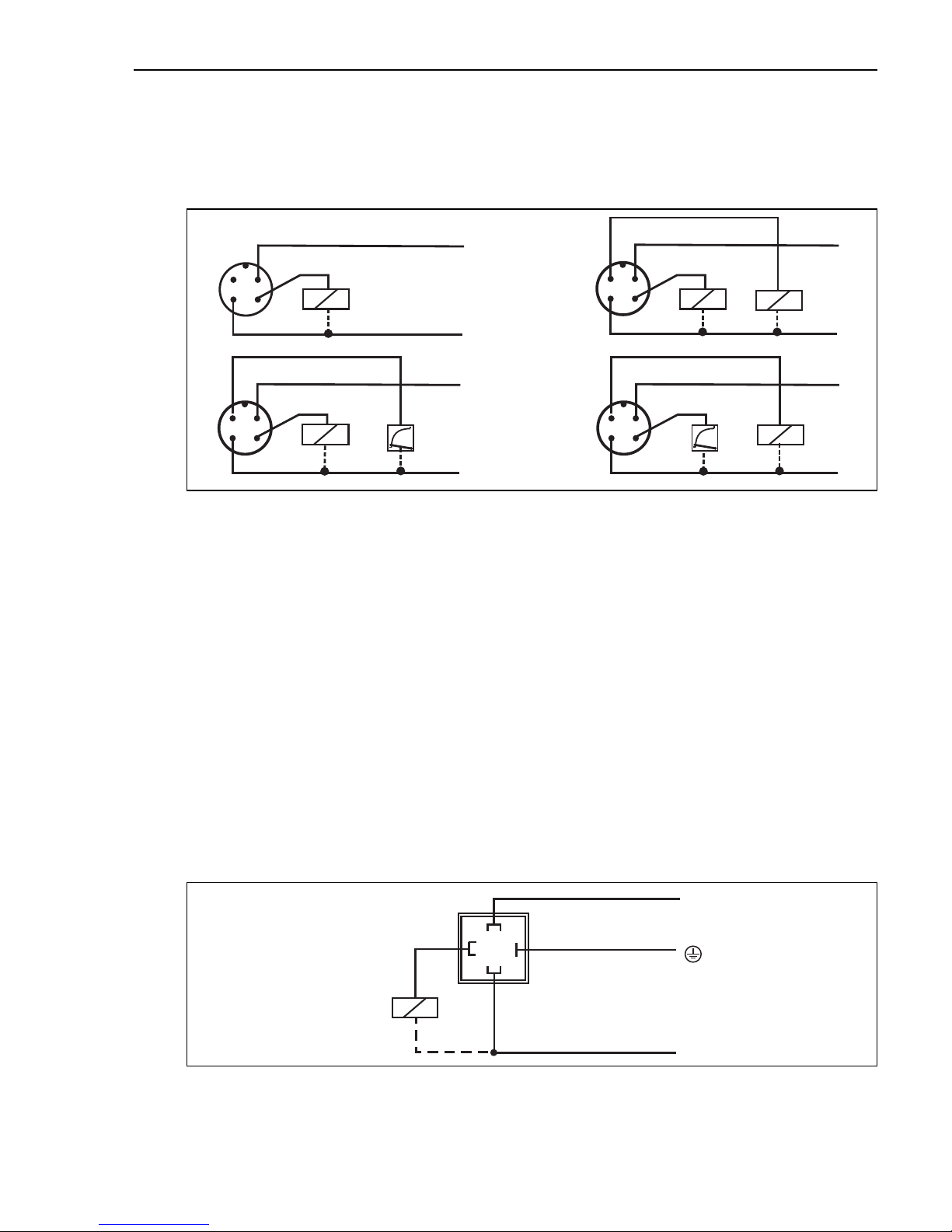
4 Wiring
4.1 DC voltage version with M12 connector
"
!
Fig. 3: Ceraphant T with M12x1 connector
P01-PTx3xxxx-04-xx-xx-xx-002
A1: 1x PNP switch output
A2: 2x PNP switch outputs R1 and m (R2)
A2’: 2x PNP switch outputs R1 and m (diagnosis/break contact with adjustment "DESINA")
A3: PNP switch output with additional analog output (active)
A3’: PNP switch output with additional analog output (active) (PIN assignment with "DESINA" setting)
Caution!
To avoid the analog input damaging of a PLC, do not connect the active PNP switch output of
the device to the 4...20 mA input of a PLC.
Note!
DESINA (see Chap. 6.2 Basic settings):
R2 = Diagnosis/break contact (more informations about DESINA see www.desina.de)
4.2 DC voltage version with valve connector
Endress+Hauser 9
Fig. 4: Ceraphant T with valve connector
B: 1x PNP switch output
P01-PTx3xxxx-04-xx-xx-xx-003
Page 10
Wiring Ceraphant T PTC31, PTP31, PTP35
L–
L–
L–
L–
L+
L+
L+
L+
R1
R1
Diag.
4...20mA
4...20mA
R1
➀
WH
WH
WH
BU
GNYE
GNYE
GNYE
GNYE
BU
BU
BU
BN
BN
BN
BN
BK
BK
BK
BK
C1
C2
C2’
C3
C3’
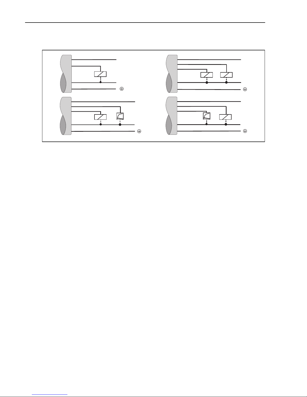
4.3 DC voltage version with cable
Fig. 5: Ceraphant T with cable connection
C1: 1x PNP switch output
C2: PNP switch outputs R1 and m(R2)
C2’: PNP switch outputs R1 and m (diagnosis/break contact with adjustment "DESINA")
C3: PNP switch output with additional analog output (active)
C3’: PNP switch output with additional analog output (active) (assignment with "DESINA" setting)
2
Cable specification: all three versions 5-core, 4 x 0.2 mm
–Core colours: BN = brown, BK = black, WH = white, BU = blue, GNYE = green/yellow
Caution!
"
(25 AWG), PE 0.75 mm2 (18 AWG)
P01-PTx3xxxx-04-xx-xx-xx-004
To avoid the analog input damaging of a PLC, do not connect the active PNP switch output of
the device to the 4...20 mA input of a PLC.
4.4 Supply voltage
DC voltage version
12...30 V DC
4.5 Current consumption
Without load < 60 mA, with reverse polarity protection
4.6 Post-connection check
10 Endress+Hauser
Perform the following checks after completing electrical installation of the device:
• Does the supply voltage match the specifications on the nameplate?
• Is the device connected as per Chap. 4.1/ Chap. 4.2/ Chap. 4.3?
• Are all screws firmly tightened?
As soon as voltage is applied to the device, the connected on-site display lights up.
Page 11

Ceraphant T PTC31, PTP31, PTP35 Operation
Operating key
Communications jack
for personal computer
Digital display
Yellow LEDs for switching states
LED on = switch closed
LED off = switch open
LED for status
Green = ok
Red = error
Red/green-blinking
= warning
E
22.07
bar
5 Operation
5.1 On-site operation
The Ceraphant T is operated by means of three keys.
!
Note!
Only use instruments with a blunt tip for operation (e.g. ballpoint pen).
Sharp instruments (e.g. needles, tweezers, pins) can destroy the operating unit.
Fig. 6: Position of operating elements and possibilities for display
Background illumination of the digital display:
–White = OK status
–Red = error status
The digital display and the light emitting diodes (LED) support navigation in the operating menu.
Endress+Hauser 11
P01-PTx3xxxx-19-xx-xx-en-003
Page 12

Operation Ceraphant T PTC31, PTP31, PTP35
A
B
E
E
E
E
E
E
E E E E
5
5
2
>3s
>3s
3
1
6
7
E
4
SAVE
bar
5.1.1 Navigating in the operating menu
P01-PTx3xxxx-19-xx-xx-xx-005
!
Fig. 7: Navigating in the operating menu
A Function group selection
B Function selection
➀ Enter the operating menu
– press the E key for longer than 3 s
➁ Select the "Function group" with the + or - key
➂ Select the "Function" with the E key
➃ Enter or change parameters with the + or - key
– then return to "Function" with th e E key Note: If software locking i s en abled, it must be disabled before making
entries or changes by entering the code selected
➄ Press the E key several times to return to the "Function group"
➅ Jump back to the measuring position (Home position)
– press the E key for longer than 3 s
➆ Query to save data (select "YES" or "NO" with the + or - key)
– confirm with the E key
Note!
Changes to the parameter settings only become effective if you choose s "YES" when asked to
save data.
12 Endress+Hauser
Page 13

Ceraphant T PTC31, PTP31, PTP35 Operation
5.1.2 Structure of the operating menu
The structure below shows all the possible fields of the operating menu.
Fig. 8: Operating menu: A function groups, B functions, C settings
Endress+Hauser 13
P01-PTx3xxxx-19-xx-xx-xx-100
Page 14

Operation Ceraphant T PTC31, PTP31, PTP35
USB
1
2
3
5.2 Operation with personal computer
The device can be configured with the configuration software ReadWin® 2000 or FieldCare.
For the connection between the USB port of the computer and the device a configuration kit
(e.g. TXU10 or FXA291)) is necessary.
Fig. 9: Operation with PC
➀ Personal computer with configuration software ReadWin 2000 or FieldCare
➁ Configuration kit (USB interface) TXU10-AA or FXA291 with USB connection
➂ Ceraphant T with communication jack
P01-PTx3xxxx-19-xx-xx-xx-004
Fig. 10: Device configuration with ReadWin
14 Endress+Hauser
Page 15

Ceraphant T PTC31, PTP31, PTP35 Operation
5.2.1 Additional operating options
In addition to the operating options listed in the previous "On-site operation" section, the
ReadWin 2000 or FieldCare configuration software provides further information on the
Ceraphant T:
Function group Description
SERV Number of switch changes for output 1
Number of switch changes for output 2
Device status
Last error to occur
INFO Tag number
Order code
Limit switch serial number
Sensor serial number
!
Electronics serial number
Device release
(change status)
Hardware version
Software version
5.2.2 Operating Instructions for ReadWin
Comprehensive information on the ReadWin configuration software may be found in the
Operating Instructions BA00137R/09/en (refer to www.readwin2000.com).
5.2.3 Operating Instructions for FieldCare
FieldCare is an universal configuration software based on FDT/DTM technology.
Note!
• To configure the Ceraphant T with FieldCare the "PCP (ReadWin) Communication DTM" and
the Ceraphant T device-DTM are required.
• All devices with software version 1.01.00 or higher can be configured with FieldCare.
• The device supports only offline configuration and up-/download of parameters. The online
configuration is not supported.
• Detailed information concerning FieldCare may be found in the operation manual BA00027S
or see: www.endress.com.
Endress+Hauser 15
Page 16

Commissioning Ceraphant T PTC31, PTP31, PTP35
6 Commissioning
6.1 Function check
Carry out a post-installation and a post-connection check as per the checklist before
commissioning the device.
• "Post-installation check" see Chap. 3.3 checklist
• "Post-connection check" see Chap. 4.6 checklist
6.2 Basic settings
Base Basic settings
Technical unit Select technical unit:
bar
psi
kPa/MPa
%
Configure zero point Offset:
±20 % URL
Accept zero point Current value as zero point (Offset
max. ±20 % URL)
1)
Display PV
Damping:
display value, output signal
DESINA
Factory setting: NO
: measured value display
PVRO: measured value display
rotated 180°
SP: set switch point display
SPRO: set switch point display
rotated 180°
OFF: display off
OFFR: display off rotated 180°
0...40 s
in increments of 0.1 s
Connection in accordance with
DESINA guidelines
(see Chap. 4)
16 Endress+Hauser
Page 17

Ceraphant T PTC31, PTP31, PTP35 Commissioning
t
t
1
2
3
4
p
a
b
p
SP
SP
RSP
RSP
0
0
0
0
1
1
1
1
Base Basic settings
!
The procentage specification applies to the upper range limit.
1) Factory setting
Note!
6.3 Output setting
• Hysteresis function: The hysteresis function enables two-point control via a hysteresis.
Depending on the pressure p, the hysteresis can be set via the switch point SP and the
switch-back point RSP.
• Window function: Enables the monitoring of a process pressure range.
The hysteresis of the switch points SP and RSP is less than 0.1 % URL. Under rough
EMC-conditions quick switching is possible if the measured value is near to SP or RSP. Setting
a damping of 0.1 s will avoid this effect.
• NO contact or NC contact: This switch function is freely selectable.
• Factory setting (if no customer-specific settings have been ordered):
Switch point SP 1: 45 %; Switch-back point RSP 1: 44.5 %
Switch point SP 2: 55 %; Switch-back point RSP 2: 54.5 %
Analog output: LRV 0 %; URV 100 %
• Range of adjustment: LRL = Lower Range Limit; URL = Upper Range Limit;
LRV = Lower Range Value; URV = Upper Range Value
Endress+Hauser 17
Fig. 11: a) Hysteresis function
b) Window function
➀ Windows NC contact switch status
➁ Hysteresis NC contact switch status
➂ Windows NO contact switch status
➃ Hysteresis NO contact switch status
SP switch point
RSP switch-back point
P01-PTx3xxxx-05-xx-xx-xx-001
Page 18

Commissioning Ceraphant T PTC31, PTP31, PTP35
OUT/OUT2 Output/output 2
1)
Switching characteristic HYNO
Hysteresis/NO contact
HYNC:
Hysteresis/NC contact
WINO:
Window/NO contact
WINC:
Window/NC contact
4...20 mA:
Analog output (only if
available)
Switch point value Switch point 0.5...100 %
URL
in increments of 0.1 % of
selected unit (min.
0.001 bar (0.015 psi))
Switch-back point value Switch-back point
0...99.5 % URL
in increments of 0.1 % of
selected unit (min.
0.001 bar (0.015 psi))
:
Switch point delay Delay time
0...99 s
in increments of 0.1 s
factory setting: 0.0
Delay time
Switch-back point delay
!
• Adjustment of measuring ranges with negative gauge pressure up to 4 bar (60 psi) in increments of min. 0.01 mbar
• Min. distance between SP and RSP: 0.5% URL
1) Factory setting
Note!
(0.15 psi).
0...99 s
in increments of 0.1 s
factory setting: 0.0
18 Endress+Hauser
Page 19

Ceraphant T PTC31, PTP31, PTP35 Commissioning
,
4 - 20 Analog output
Value for 4 mA
(LRV)
Value for 20 mA
(URV)
Pressure applied for
4 mA (LRV)
Pressure applied for
20 mA (URV)
Error current Current value in event of
!
Turndown up to 4:1, LRV must be lower than URV
1) Factory setting
Note!
Enter lower range value in
increments of 0.1 % of
selected unit
Enter upper range value in
increments of 0.1 % of
selected unit
Take pressure value as
lower range value
Take pressure value as
upper range value
error:
MIN = 3.6 mA
1)
= 21.0 mA
MAX
HOLD = last value
6.4 Service function setting
• Locking code
A locking code already assigned can only be changed by first entering the old code for enabling
the device.
SERV Service functions
Security locking Locking against undesired
configuration
Locking code Freely selectable code
1...9999
0 = no locking
Reset Reset all entries to the
factory setting
Revision counter Increases by 1 with each
configuration
Last device status Displays the last device
status to occur 0
Endress+Hauser 19
Page 20

Maintenance Ceraphant T PTC31, PTP31, PTP35
,
SERV Service functions
Simulation
output 1 or 2
Max. indicator Display of max. measured
Min. indicator Display of min. measured
7Maintenance
Ceraphant T requires no maintenance.
7.1 Exterior cleaning
OFF: No simulation
OPEN: Switch output
open
CLOS: Switch output
closed
3.5: Simulation values for
analog output in mA
(3.5/4.0/8.0/12.0/16.0/
20.0/21.7)
process value
process value
Please note the following points when cleaning the device:
• The cleaning agents used should not attack the surface and the seals.
• Mechanical damage to the process isolating diaphragm, e.g. due to pointed objects, must be
avoided.
• Observe degree of protection. See therefor nameplate if necessary (Page 5).
20 Endress+Hauser
Page 21

Ceraphant T PTC31, PTP31, PTP35 Accessories
M24x1.5
PTC31
PTP31, PTP35
2
3
4
5
1
8 Accessories
8.1 Process connection
• Ceraphant T PTC31:
The sensor module and the process connection are connected together and cannot be
separated.
• Ceraphant T PTP31, PTP35:
The process connection is an adapter and the sensor module has an adapter thread. As a result,
the process connection can easily be changed at a later stage.
Exceptions:
Process connection G ½A flush mounted, Clamp ½ and G 1A and 400 bar (6000 psi) sensors.
Fig. 12: Process connection
➀ Sensor module PTC31
➁ Sensor module PTP31 and PTP35
➂ Adapter with threaded connection (apart from G ½A flush mounted)
➃ Adapter with Clamp connection (apart from Clamp ½")
➄ Adapter with hygiene connection (apart from G 1A)
Endress+Hauser 21
P01-PTx3xxxx-06-xx-xx-xx-006
Page 22

Accessories Ceraphant T PTC31, PTP31, PTP35
PTP31
PTP35
1
1
2
2
3
3
8.1.1 Adapter change
The adapter can be changed on PTP31 and PTP35.
!
Fig. 13: Changing the adapter
P01-PTx3xxxx-17-xx-xx-xx-001
➀ Sensor module with adapter thread
➁ Standard O-ring
➂ Adapter
Please note the following when changing the adapter:
• Use a new O-ring. Diameter 15.54 (0.61 in) x 2.62 mm (0.1 in).
With either EPDM 70 Shore FDA or FKM 70 Shore material.
• The device (sensor module) can be fixed in place with an open-ended wrench AF 27mm.
• The adapter can be screwed on with an open-ended wrench AF 28mm or AF 32mm
(depending on the process connection).
The maximum torque is 80 Nm (59 lbs ft). The thread can become loose if exposed to severe
strain through pressure and temperature. For this reason, the air-tightness must be checked
regularly and the thread tightened if necessary.
• When changing the adapter, make sure that the process isolating diaphragm of the sensor is
not damaged.
Note! O-ring change:
We recommend to change the O-ring in the same time frame as of all other sealings in your
process.
22 Endress+Hauser
Page 23

Ceraphant T PTC31, PTP31, PTP35 Accessories
Ø17.3 (0.7)
1/2"NPT
Ø11.4 (0.45)
25.15
(0.99)
DA
CA
Ø23 (0.9)
15.5
(0.61)
1/4 NPT
Ø11.4 (0.45)
Ø26 (1.02)
34 (1.34)
15.5
(0.61)
7/16-20 UNF
BA
DD
Ø23 (0.9)
15.5
(0.61)
M12x1.5
34 (1.34)
34 (1.34)
47 (1.85)
Ø17.5 (0.69)
Ø23 (0.9)
G1/4
3 (0.12)
3 (0.12)
Ø6 (0.24)
Ø3 (0.12)
Ø17.5 (0.69)
G1/2A
20 (0.79)
Ø11.4 (0.45)
G1/4A
Ø3 (0.12)
AC
AD
AE
AF
34 (1.34)
45 (1.77)
15.5
(0.61)
12
(0.47)
34 (1.34)
42 (1.65)
G1/2A
20 (0.79)
mm (inch
)
8.1.2 Adapter versions
• PTP31: order numbers for thread adapter versions.
Version AC: order no. 52023980
Version AD: order no. 52023981
Version AE: order no. 52023982
Version AF: order no. 52023983
Version BA: order no. 52023984
Version CA: order no. 52023985
Version DA: order no. 52023986
Version DD: order no. 52023987
Endress+Hauser 23
P01-PTx3xxxx-06-xx-xx-xx-020
Page 24

Accessories Ceraphant T PTC31, PTP31, PTP35
DB
DL
8.5 (0.3)
17 (0.7)
Ø56.5 (2.2)
Ø64 (2.5)
10 (0.4)
17 (0.7)
SW28
AF28
SW32
AF32
Ø43.5 (1.7)
Ø50.5 (2.0)
mm
(inch)
Ø50 (2)
Ø66 (2.6)
Ø61,5 (2.4)
Ø66,2 (2.6)
Ø82 (3.2)
Ø100 (3.9)
LB
PH
KL
PL
HL
LL
Ø68 (2.7)
Ø84 (3.3)
18 (0.7)
Ø51 (2)
Ø68 (2.7)
Ø39 (1.5)
Ø56 (2.2)
17(0.7)
19 (0.7)
Ø54.85 (2.16)
SW32
AF32mm
17 (0.7)
mm
(inch)
SW32
AF32mm
17(0.7)
SW32
AF32mm
• PTP35: order numbers for Clamp adapter
versions (EHEDG, 3A).
Version DB: order no. 52023994
Version DL: order no. 52023995
Optional with inspection certificate 3.1:
Version DB: order no. 52024001
Version DL: order no. 52024002
P01-PTx3xxxx-06-xx-xx-xx-009
• PTP35: order numbers for hygiene
adapter versions (EHEDG, 3A).
Version LB: order no. 52023996
Version LL: order no. 52023997
Version PH: order no. 52023999
Version PL: order no. 52023998
Version HL: order no. 52024000
Version KL: order no. 52026997
Optional with inspection certificate 3.1:
Version LB: order no. 52024003
Version LL: order no. 52024004
Version PH: order no. 52024006
Version PL: order no. 52024005
Version HL: order no. 52024007
Version KL: order no. 52026999
8.1.3 O-ring for adapter change
P01-PTx3xxxx-06-xx-xx-xx-010
• O-ring 15.54 x 2.62 mm (0.61 x 0.1 in), EPDM 70 Shore FDA, order number 52024267
• O-ring 15.54 x 2.62 mm (0.61 x 0.1 in), FKM 70 Shore, order number 52024268
24 Endress+Hauser
Page 25

Ceraphant T PTC31, PTP31, PTP35 Accessories
ø50 (1,97)
30
(1.18)
27.5
(1.08)
mm
(inch)
ø60 (2.4)–0.4
24.6 (0.97)
29.6 (1.2)
ø41 (1.6)
G1
mm (inch)
8.2 Welding bosses
8.2.1 Welding boss with sealing taper
• Welding boss for flush mounting process
connection G1A with metallic sealing
taper (version BA for PTP35)
Material: AISI 316L
Order number: 52005087
• Optional with inspection certificate 3.1
Order number: 52010171
• Welding aid (Dummy) for welding the
welding boss without any problems, order
number 52005087 or 52010171
Material: brass
Order number: 52005272
P01-Pxxxxxxx-00-xx-00-xx-00 1
8.2.2 Welding boss with sealing surface
• Welding boss for flush mounting process
connection G1 A (ISO 228) with sealing
surface (version BB for PTP35)
Material: AISI 316L
Order number: 52001051
• Seal (enclosed): silicone O-ring
FDA approved materials according to
21 CFR Part 177.1550/2600
• Optional with inspection certificate 3.1
Order number: 52011896
P01-PMP13xxx-00-xx-00-xx-002
Endress+Hauser 25
Page 26

Accessories Ceraphant T PTC31, PTP31, PTP35
20 (0.8)
41 (1.6)
35 (1.4)
14.8 (0.6)
mm (inch)
ye2
ye1
gn
2
R
R
2 (wh)
1
1 (bn)
3
3 (bu)
4
4 (bk)
L–
L+
8.3 Electrical connection
8.3.1 Plug-in jack, connecting cable
• M12x1 plug-in jack. Connection to
M12x1 housing connector
Materials: Body PA, coupling nut Cu Zn,
brass, nickeled.
Protection: IP 67 (fully locked).
Order number: 52006263
• M12x1 plug-in jack, elbowed
Connection to M12x1 housing connector
Materials: Body PBT/PA, coupling nut
GD-Zn, brass, nickeled
Protection: IP 67 (fully locked)
Order number: 51006327
P01-PMP13xxx-00-xx-00-xx-003
• Cable, 4 x 0.34 mm2 (22 AWG)
with M12 socket,
elbowed, screw plug, length 5 m (16 ft)
Materials: Body PUR; coupling nut
Cu Zn/Ni, brass, nickeled; cable: PVC
Protection: IP 67 (fully locked)
Order number: 52010285
2
• Cable, 4 x 0.34 mm
(22 AWG) with
M12 socket, with LED, elbowed, screw
plug, PVC cable. For devices with switch
output only.
Materials: Body PVC, coupling nut 316L,
Protection: IP 69K (fully locked)
Order number: 52018763
P01-Pxxxxxxx-00-xx-00-xx-00 2
P01-PTx3xxxx-07-xx-xx-xx-001
26 Endress+Hauser
Page 27

Ceraphant T PTC31, PTP31, PTP35 Accessories
8.4 ReadWin
• Configuration kit for
PC-programmable
transmitters. Setup program and
interface cable for PCs with USB
port. Adapter for transmitters with
4-pin post connector.
Order code: TXU10-AA
®
•ReadWin
configuration kit or it can be
downloaded free of charge directly
from the internet at the following
address:
www.readwin2000.com
2000 is supplied with the
P01-PTxx3xxx-00-xx-00-xx-001
Endress+Hauser 27
Page 28

Trouble-shooting Ceraphant T PTC31, PTP31, PTP35
9 Trouble-shooting
9.1 Errors and warnings
If an error in the device occurs, the colour of the status LED changes from green to red and the
background illumination of the digital display changes from blue to red. The measured value and
message are displayed alternately. The display shows:
• E-code for errors. In the event of error messages, the measured value is uncertain.
• W-code for warnings. In the event of a warning, the measured value is reliable.
E-Code Explanation Remedy
E011 Device configuration defective Reset device (see Chap. 6.4)
E012 Error in measurement or
pressure out of specification
E019 Power supply outside specification Check operating voltage
E015
E020
E021
E022 Power is only supplied to the device via the
E025 Switching contact 1 is not open although it
E026 Switching contact 2 is not open although it
E040 VCC (controller voltage) is out of working area Return device to Endress+Hauser
E042 Output current can no longer be generated (only
E044 Output current drifts too much (±0.5 mA) Return device to Endress+Hauser
Memory error Return device to Endress+Hauser
communication interface (measurement is
deactivated)
should be
should be
for 4 to 20 mA output, e.g. load at analog output
too high or open analog output)
Check pressure, return device to Endress+Hauser
where necessary
Check operating voltage
Switching contact defective.
Return device to Endress+Hauser
Switching contact defective.
Return device to Endress+Hauser
Check load; switch off analog output via
configuration if it isn’t required (see
Chap. 6.3)
W-Code Explanation Remedy
W107 Simulation active Switch off the output simulation for output 1 and
W202 Pressure outside the sensor range Operate the device in the specified pressure range
W209 Device starts
W210 Configuration modified (warning code will be
displayed for 15 s approx.)
28 Endress+Hauser
output 2
Page 29

Ceraphant T PTC31, PTP31, PTP35 Trouble-shooting
W-Code Explanation Remedy
W212 Sensor signal outside the permitted range Operate the device in the specified pressure range
W250 Number of switch cycles exceeded Replace the device
W270 Short-circuit and overload at output 1 Check output wiring. Extend the load resistance
at output 1
W280 Short-circuit and overload at output 2 Check output wiring. Extend the load resistance
at output 2
9.2 Repair
A repair is not planned.
9.3 Return
The measuring device must be returned if repairs or a factory calibration are required, or if the
wrong measuring device has been ordered or delivered. According to legal regulations,
Endress+Hauser, as an ISO-certified company, is required to follow certain procedures when
handling returned products that are in contact with medium.
To ensure swift, safe and professional device returns, please read the return procedures and
conditions on the Endress+Hauser website at www.services.endress.com/return-material
9.4 Disposal
When disposing, ensure that the materials of the device components are separated and processed
accordingly.
9.5 Change status (release)
The release number on the nameplate and in the Operating Instructions indicates the change
status of the device: X.YY. (example 1.02. ).
X Change in the main version.
Compatibility no longer provided. Device and Operating Instructions change.
YY Compatibility provided. Operating Instructions change.
Endress+Hauser 29
Page 30

Technical data Ceraphant T PTC31, PTP31, PTP35
9.6 Change status - history
Release no. device Changes
1.00
1.01 New analog electronics
1.02 Modification sensor units
1.03 Internal device modification
1.04 Internal device modification
1.05 Internal device modification
10 Technical data
For technical data, please refer to the Technical Information Ceraphant T TI00384P.
30 Endress+Hauser
Page 31

Ceraphant T PTC31, PTP31, PTP35 Index
Index
A
Adapter change . . . . . . . . . . . . . . . . . . . . . . . . . 22
Adapter versions . . . . . . . . . . . . . . . . . . . . . . . . 23
Additional operating options . . . . . . . . . . . . . . . 15
M
Mounting instructions . . . . . . . . . . . . . . . . . . . . . 8
N
Navigating in the operating menu . . . . . . . . . . . 12
O
Operating Instructions for FieldCare. . . . . . . . . . 15
Operating Instructions for ReadWin . . . . . . . . . . 15
O-ring for adapter change . . . . . . . . . . . . . . . . . 24
P
Plug-in jack, connecting cable . . . . . . . . . . . . . . 26
S
Structure of the operating menu. . . . . . . . . . . . . 13
W
Welding boss with sealing surface . . . . . . . . . . . 25
Welding boss with sealing taper . . . . . . . . . . . . . 25
Endress+Hauser 31
Page 32

www.endress.com/worldwide
KA00225P/00/EN/16.15
71302114
71302114
FM+SGML 9.0
 Loading...