

Page 1

UltraProteus
Operation Manual
© 1994 E-mu Systems, Inc.
All Rights Reserved
FI434 Rev. A
Manual - Riley Smith
E-mu World Headquarters
E-mu Systems, Inc. U.S.A.
P.O. Box 660015
Scotts Valley, CA USA
95067–0015
Telephone: 408-438-1921
Fax: 408-438-8612
Important Notice:
In order to obtain warranty service on your UltraProteus unit, the serial number sticker must be intact and you must
have a sales receipt or other proof of purchase. If there is no serial number sticker on UltraProteus, please contact
E-mu Systems at once.
This product is covered under one or more of the following U. S. patents: 3,969,682; 3,986,423; 4,404,529;
4,506,579; 4,699,038; 4,987,600; 5,013,105; 5,072,645; 5,111,727 and foreign patents and/or pending
patents. UltraProteus is a registered trademark of E-mu Systems, Inc.
Europe, Africa, Middle East
E-mu Systems, Ltd.
Suite 6, Adam Ferguson House
Eskmills Industrial Park
Musselburgh, East Lothian
Scotland, EH21 7PQ
Telephone: 44-31-653-6556
Fax: 44-31-665-0473
PRINTED AND MADE IN THE USA
Page 2
IMPORTANT SAFETY INSTRUCTIONS
Use in countries other than the U.S.A. may require the use of a different line
cord or attachment plug, or both. To reduce the risk of fire or electric shock,
refer servicing to qualified service personnel. To reduce risk of fire or electric
shock do not expose this product to rain or moisture.
WARNING: READ THIS FIRST!
GROUNDING INSTRUCTIONS
This product must be grounded. If it should malfunction or break down,
grounding provides a path of least resistance for electric current, reducing the
risk of electric shock. This product is equipped with a cord having an equipment-grounding conductor and a grounding plug. The plug must be plugged
into an appropriate outlet properly installed and grounded in accordance with
all local codes and ordinances.
DANGER
Improper connection of equipment grounding conductor can result in the risk
of electric shock. Check with a qualified electrician or service personnel if you
are in doubt as to whether the product is properly grounded. Do not modify the
plug provided with this product — if it will not fit the outlet, have a proper
outlet installed by a qualified technician.
CAUTION
If the UltraProteus (model number 9053), is rack mounted, a standard 19-inch
open frame rack must be used.
USER-MAINTENANCE INSTRUCTIONS
1. UltraProteus should be kept clean and dust free. Periodically wipe the unit
with a clean, lint free cloth. Do not use solvents or cleaners.
2. There are no user lubrication or adjustment requirements.
In this document, whenever the
word “UltraProteus” is
mentioned, we are referring to
the UltraProteus Synthesizer by
E-mu Systems, Inc.
This symbol is intended to alert
the user to the presence of
important operating and
maintenance (servicing)
instructions in the literature
accompanying the appliance.
3. Refer all other servicing to qualified service personnel.
INSTRUCTIONS PERTAINING TO A RISK OF FIRE, ELECTRIC SHOCK, OR
INJURY TO PERSONS
WARNING; When using electric products, basic precautions
should always be followed, including the following:
1. Read all instructions before using UltraProteus.
2. To reduce the risk of injury, close supervision is necessary when UltraProteus
is used near children.
3. Do not use UltraProteus near water — for example near a bathtub, washbowl,
kitchen sink, in a wet basement, on a wet bar, or near or in a swimming pool.
4. UltraProteus should be situated so that its location or position does not
interfere with its proper ventilation.
This symbol is intended to alert
the user to the presence of
uninsulated dangerous voltage
within the product's enclosure
that may be of sufficient
magnitude to constitute a risk of
electric shock to persons.
i
Page 3

SAVE THESE INSTRUCTIONS
5. UltraProteus should be located away from heat sources such as radiators, heat
registers, fireplaces, stoves, or ovens.
6. UltraProteus should only be connected to a power supply of the type described in the operating instructions and as marked on the product.
7. This product, in combination with an amplifier, headphones, and speakers,
may be capable of producing sound levels that could cause full or partial
hearing loss or damaged equipment. Do not operate for long periods of time
at high volume levels or at a level that is uncomfortable. Additionally, care
must be taken when programming any of the filters contained herein using
extreme operating parameters. This action could also produce signals which
result in unacceptable high sound levels as noted previously. If you experience any hearing loss or ringing of the ears consult your physician.
8. UltraProteus may be equipped with a polarized line plug (one blade wider that
the other). This is a safety feature. If you are unable to insert this plug into
the outlet, do not defeat the safety purpose of the plug. Contact an electrician
to replace your obsolete outlet.
9. The power supply cord of UltraProteus should be unplugged from the outlet
when left unused for a long period of time.
10. Care should be taken so that objects do not fall and liquids are not spilled
into the enclosure of UltraProteus through openings.
11. The product should be serviced by qualified service personnel when:
A. The power supply cord has been damaged; or
B. Objects have fallen on, or liquid has been spilled into the product; or
C. The product has been exposed to rain; or
D. The product does not appear to operate normally or exhibits a
marked change in performance; or
E. The product has been dropped or the enclosure damaged.
12. All servicing should be referred to qualified service personnel.
SAVE THESE INSTRUCTIONS
ii
Page 4

INTRODUCTION & BASIC SETUP 1
Introduction .................................................................................................................... 3
Getting Started ................................................................................................................ 4
Connection Instructions .................................................................................................... 5
Background - About Sampling.......................................................................................... 9
TABLE OF CONTENTS
BASIC OPERATION
Main Controls ................................................................................................................ 12
Selecting MIDI Channels................................................................................................. 14
Selecting Presets/Hyperpresets ...................................................................................... 14
Adjusting Volume & Pan Position .................................................................................... 14
Memory Card ................................................................................................................ 15
Midimap Selection ......................................................................................................... 15
Multi-Timbral Operation................................................................................................. 16
Playing the Demo Sequences ......................................................................................... 16
Master Menu ................................................................................................................. 17
Enabling the Master Menu ............................................................................................. 19
Master Tune .................................................................................................................. 19
Transpose...................................................................................................................... 19
User Key Tuning ............................................................................................................ 20
Global Bend .................................................................................................................. 20
Global Velocity Curve ..................................................................................................... 20
MIDI Mode .................................................................................................................... 22
MIDI Mode Change ........................................................................................................ 22
MIDI Program Change Map............................................................................................ 23
MIDI Controller Assign ................................................................................................... 24
MIDI Footswitch Control ................................................................................................. 24
Send MIDI Data ............................................................................................................. 24
Sysex Packet Delay ....................................................................................................... 25
Proteus Sysex................................................................................................................ 26
Auto Select .................................................................................................................... 26
Compare Mode .............................................................................................................. 26
Viewing Angle ............................................................................................................... 26
Midimap Menu .............................................................................................................. 27
The Midimap ................................................................................................................. 29
Enabling the Midimap Menu........................................................................................... 30
Midimap Select .............................................................................................................. 30
Midimap Name.............................................................................................................. 31
Program to Channel Assign ............................................................................................ 31
Volume, Pan & Output Mix ............................................................................................ 31
11
iii
Page 5

TABLE OF CONTENTS
MIDIMAP MENU (cont)
MIDI Enables ................................................................................................................. 33
Bank Select ................................................................................................................... 33
Program Map Select ...................................................................................................... 34
FX A.............................................................................................................................. 34
FX B.............................................................................................................................. 35
FX Amount .................................................................................................................... 35
FX Output Select ............................................................................................................ 36
Save Midimap ............................................................................................................... 36
EFFECTS SECTION
Where are the Effects? ................................................................................................... 39
Effects Output Routing ................................................................................................... 40
UltraProteus Effects Bus Architecture .............................................................................. 40
Effect Programming Instructions..................................................................................... 41
Reverb .......................................................................................................................... 42
Stereo Flanger ............................................................................................................... 46
Stereo Phaser ................................................................................................................ 48
Stereo Chorus ................................................................................................................ 49
Stereo Delay ................................................................................................................. 50
Stereo Cross Delay......................................................................................................... 51
Stereo Echo ................................................................................................................... 52
“B” Effects .................................................................................................................... 53
Stereo Fuzz ................................................................................................................... 54
Ring Modulator ............................................................................................................. 55
HYPERPRESET MENU
The Hyperpreset ............................................................................................................ 59
Enabling the Hyperpreset Menu ..................................................................................... 59
Hyperpreset Name ........................................................................................................ 60
Preset to Zone Assignment ............................................................................................. 60
Zone Volume and Pan.................................................................................................... 61
Zone Key Range ............................................................................................................ 61
Zone Velocity Range ...................................................................................................... 62
Zone Velocity Offset ...................................................................................................... 63
Zone Transpose ............................................................................................................. 63
Zone Pitch Tune............................................................................................................. 63
Hyperpreset Portamento Mode....................................................................................... 64
Free-Run Function Generator ......................................................................................... 64
Save Hyperpreset .......................................................................................................... 66
37
57
iv
Page 6

TABLE OF CONTENTS
PRESET PROGRAMMING
Starting to Program ....................................................................................................... 69
Modulation.................................................................................................................... 70
Modulation Sources ....................................................................................................... 71
Footswitch Modulation ................................................................................................... 72
Midipatch ...................................................................................................................... 72
Envelope Generators...................................................................................................... 73
Low Frequency Oscillators .............................................................................................. 75
Function Generators ...................................................................................................... 76
Filter Modulation ........................................................................................................... 84
Parametric Filters .......................................................................................................... 87
The UltraProteus Filter ................................................................................................... 88
The Z-Plane Filter .......................................................................................................... 89
Another View ................................................................................................................. 92
UltraProteus Signal Flow ................................................................................................ 93
Note-On Modulation Control........................................................................................... 94
Realtime Modulation Control .......................................................................................... 95
Key Number .................................................................................................................. 96
Velocity Curves .............................................................................................................. 96
MIDI Realtime Controls .................................................................................................. 97
67
PRESET MENU
Enabling the Preset Menu ............................................................................................ 101
Preset Name ............................................................................................................... 102
Primary Instrument ..................................................................................................... 102
Secondary Instrument.................................................................................................. 102
Volume ....................................................................................................................... 103
Pan ............................................................................................................................. 103
Key Range .................................................................................................................. 103
Primary Key Range ..................................................................................................... 104
Secondary Key Range .................................................................................................. 104
Transpose.................................................................................................................... 105
Coarse Pitch Tuning ..................................................................................................... 105
Fine Pitch Tuning ......................................................................................................... 105
Alternate Envelope On/Off .......................................................................................... 105
Primary Alternate Envelope Parameters ....................................................................... 106
Secondary Alternate Envelope Parameters .................................................................... 106
Double + Detune......................................................................................................... 106
Sound Delay................................................................................................................ 107
Sound Start ................................................................................................................. 107
99
v
Page 7

TABLE OF CONTENTS
PRESET MENU (cont)
Sound Reverse ............................................................................................................ 107
Nontranspose .............................................................................................................. 108
Loop Enable ................................................................................................................ 108
Loop Offset ................................................................................................................. 108
Solo Mode ................................................................................................................... 109
Solo Mode Priority ....................................................................................................... 110
Portamento Rate ......................................................................................................... 110
Portamento Shape ....................................................................................................... 110
Portamento Mode ........................................................................................................ 111
Crossfade Mode ........................................................................................................... 111
Crossfade Direction ...................................................................................................... 112
Crossfade Balance and Amount .................................................................................... 112
Cross-switch Point ........................................................................................................ 113
Primary Filter Type ...................................................................................................... 113
Secondary Filter Type .................................................................................................. 113
Filter Level .................................................................................................................. 113
Morph Offset ............................................................................................................... 114
Filter Frequency Tracking ............................................................................................. 114
Filter Transform 2........................................................................................................ 115
Filter Reverse .............................................................................................................. 116
Auxiliary Envelope ...................................................................................................... 116
LFO 1 & 2 - Shape & Amount ....................................................................................... 117
LFO 1 & 2 - Rate, Delay & Variation ............................................................................. 117
Function Generator 1 and 2 ......................................................................................... 118
Note-On Modulation Control......................................................................................... 122
Realtime Modulation Control ........................................................................................ 123
Footswitch Control ....................................................................................................... 124
Pitch Bend Range ........................................................................................................ 124
Pressure Amount ......................................................................................................... 124
MIDI Controller Amount ............................................................................................... 124
Velocity Curve ............................................................................................................. 125
Keyboard Center ......................................................................................................... 126
Keyboard Tuning ......................................................................................................... 126
Mix Select ................................................................................................................... 127
Save Preset ................................................................................................................. 127
vi
Page 8

TABLE OF CONTENTS
COPY MENU
Enabling the Copy Menu .............................................................................................. 131
Copy Preset ................................................................................................................. 131
Copy Layer.................................................................................................................. 132
Copy Filter .................................................................................................................. 132
Copy LFO .................................................................................................................... 132
Copy Function Generator ............................................................................................. 133
Copy Auxiliary Envelope .............................................................................................. 133
Copy Note-On Control .................................................................................................. 133
Copy Realtime Control ................................................................................................. 133
Copy Hyperpreset ........................................................................................................ 134
Copy Zone................................................................................................................... 134
Copy Free-Run Function Generator ............................................................................... 134
Copy Midimap ............................................................................................................. 134
Copy Channel .............................................................................................................. 135
Copy Effects ................................................................................................................ 135
Copy Program Change Map.......................................................................................... 135
Copy Bank .................................................................................................................. 136
129
STEP-BY-STEP
Forward ...................................................................................................................... 139
Editing Presets............................................................................................................. 139
Starting From Scratch .................................................................................................. 140
The Instrument ............................................................................................................ 140
Volume ....................................................................................................................... 141
Pan ............................................................................................................................. 141
Transpose.................................................................................................................... 141
Coarse Tuning ............................................................................................................. 142
Fine Tuning ................................................................................................................. 142
Alternate Volume Envelope .......................................................................................... 143
Anatomy of an Envelope.............................................................................................. 144
Sound Delay................................................................................................................ 145
Sound Start ................................................................................................................. 145
Application: Sound Splicing .......................................................................................... 146
Time to Save?.............................................................................................................. 147
LFO Modulation ........................................................................................................... 147
Modulating Modulators ................................................................................................ 150
The UltraProteus Filter ................................................................................................. 151
Just Do It .................................................................................................................... 152
Filter Filosophy............................................................................................................ 154
137
vii
Page 9

TABLE OF CONTENTS
STEP-BY-STEP (cont)
Morphology ................................................................................................................ 157
Using UltraProteus with a Sequencer ............................................................................ 158
More Advanced Sequencing ......................................................................................... 159
REFERENCE SECTION
Factory RAM Presets - Bank 0 ...................................................................................... 162
Factory ROM Presets - Bank 1 ...................................................................................... 163
Instrument Listing........................................................................................................ 164
B3 Wave Diagrams ...................................................................................................... 171
Instrument Locations ................................................................................................... 172
Percussion Instrument Locations ................................................................................... 173
Z-Plane Filter Descriptions............................................................................................ 178
Loop Offset Sample Locations....................................................................................... 235
Function Generator Curves ........................................................................................... 239
Function Generator, LFO & Envelope Specifications ....................................................... 247
Technical Specifications ................................................................................................ 248
MIDI Implementation Chart.......................................................................................... 249
MIDI Specifications ...................................................................................................... 250
SysEx Tutorial ............................................................................................................. 277
INDEX
WARRANTY
161
281
285
viii
Page 10

UltraProteus INTRO/BASIC SETUP
Chapter 1: Basic Setup 1
Page 11

UltraProteus Operation Manual2
Page 12

PHONES
VOLUME
UltraProteus
C01 VOL127 PAN=P
195 Star Ship
HYPERPRESETMIDIMAP COPY
DEMO
CURSOR
HOME/ENTER
POWER
DATA
MIDI
<>
PRESETMASTER
UltraProteus
UltraProteus is a new type of music synthesizer which upholds the legendary
Proteus tradition of crystal-clear sounds while significantly furthering the
evolution of electronic sound synthesis.
Many electronic instruments today involve the technology of sampling, where
sounds are digitally recorded and played back at different pitches. Sampling has
the advantage of highly accurate and realistic sound. One disadvantage of
sampling is that once the sounds are recorded, it is difficult to change them in
any significant way.
INTRODUCTION
THIS SYMBOL APPEARS
THOUGHOUT THE MANUAL TO
HIGHLIGHT ADDITIONAL
INFORMATION RELATING TO THE
OPERATION OF ULTRAPROTEUS.
UltraProteus incorporates the E-mu Z-Plane filter, which has the ability to
smoothly change its function over time. This ultra-powerful device can accurately simulate the resonance of musical instruments, the human voice or
create entirely new timbres. The Z-Plane filter is composed of up to eight
complex filters for unprecedented control over subtle aspects of the sound.
UltraProteus contains sixteen megabytes of Pop, Rock, Orchestral and World
samples from the Proteus family of instruments. In addition, it includes hot
™
new drum sounds, new waveforms, and the Proformance
stereo grand piano.
This amazing array of sounds can be combined or spliced, modulated and then
shaped through one of 288 Z-Plane filters. Sampled sounds can be re-shaped
and expressively controlled, allowing you to articulate the subtle nuances of
complex instruments.
The 16 bit sound samples are arranged into 256 preset locations, 128 of which
are user-programmable. 128 user-programmable Hyperpresets allow ultraflexible keyboard mapping of presets. The optional memory card lets you create
an expandable library of your favorite presets and hyperpresets.
UltraProteus features two studio-quality effects processors with 28 different
effects to choose from. Hyperpresets allow you to have up to 32 different sounds
on the keyboard at one time in any desired arrangement. Sounds can be placed
side by side or layered with velocity control. The ability to respond multitimbrally to all 16 MIDI channels makes UltraProteus ideally suited for multitrack sequencing and composing using a MIDI sequencer.
THIS SYMBOL APPEARS
THOUGHOUT THE MANUAL
TO WARN YOU OF
POTENTIALLY CONFUSING
OPERATING PROCEDURES.
Other features include 3 stereo outputs for individually processing sounds (also
configurable as 6 polyphonic submixes with fully programmable panning),
integral sends and returns to allow the addition of external effects units without
the need for a separate mixer, user definable alternate tuning, and of course, an
extensive MIDI implementation.
Chapter 1: Basic Setup 3
Page 13
INSTRUMENT
INSTRUMENT
PRESET
PRIMARY
SECONDARY
GETTING STARTED
• RAM PRESETS CAN BE
MOVED, ERASED OR MODIFIED
AS DESIRED.
• ROM PRESETS CANNOT BE
MOVED OR ALTERED UNLESS
THEY ARE FIRST COPIED TO A
RAM LOCATION.
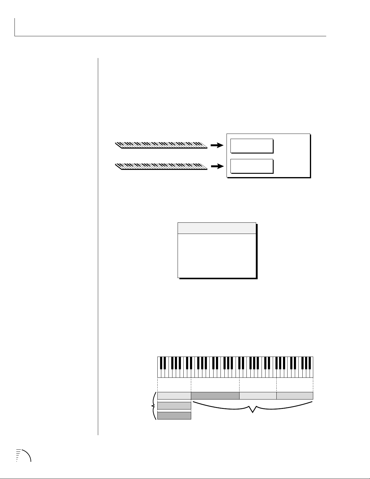
In its most basic form, UltraProteus is organized as shown in the diagram
below. Complete acoustic instrument samples and electronically created sounds
are used as raw material to form Presets.
The Preset is a complete set of all program functions and combinations for a
complete UltraProteus sound. Each preset consists of one or two Instruments.
An Instrument is a complete set of samples or a digital waveform which covers
the entire keyboard range. An instrument can be assigned to each of the Primary and Secondary layers of the preset.
The primary and secondary layers of the preset are essentially two instruments
with complete modulation controls. The memory is organized into banks of 128
programmable RAM presets, unalterable ROM presets and Hyperpresets.
Bank Contents
-
RAM Presets
O
-
ROM Presets
1
-
RAM Hyperpresets
2
-
Card Presets
3
-
Card Hyperpresets
4
• HYPERPRESETS ARE GROUPS
OF PRESETS ARRANGED ON THE
KEYBOARD TO FORM SPLITS OR
LAYERS.
• MEMORY CARD - ALLOWS
YOU TO EASILY LOAD AND SAVE
ADDITIONAL PRESETS AND
HYPERPRESETS.
A Hyperpreset is a combination of up to sixteen presets arranged either side by
side on the keyboard (to create a keyboard split) or on top of each other (to
create a denser sound). Each preset in a hyperpreset is assigned to a keyboard
Zone, with an associated key range, volume, pan, tuning and transpose setting.
In addition, each zone can be assigned to a velocity range so that different
presets can play depending on the key velocity. There are 128 Hyperpreset
locations available to store your own custom keyboard setups.
- Layer -
Presets Assigned
to the same
Keyboard Range
(3 Zones)
Preset
Preset
Preset
(Zone) (Zone)
Preset
Preset
- Keyboard Split -
Presets Placed
Adjacent to Each Other
(Zone)
Preset
UltraProteus Operation Manual4
Page 14
100-250VAC 50/60 Hz ~
Aux. or
Tape In
MIDI Controller
(MIDI Keyboard, Sequencer, etc.)
Control
Pedal
E-MU SYSTEMS, INC.
Scotts Valley, California U.S.A.
WARNING: TO REDUCE THE RISK OF FIRE
OR ELECTRIC SHOCK, DO NOT EXPOSE
THIS PRODUCT TO RAIN OR MOISTURE.
Male RCA plug
to
Male Phono Plug
MIDI Out
MIDI
To
Main Outs
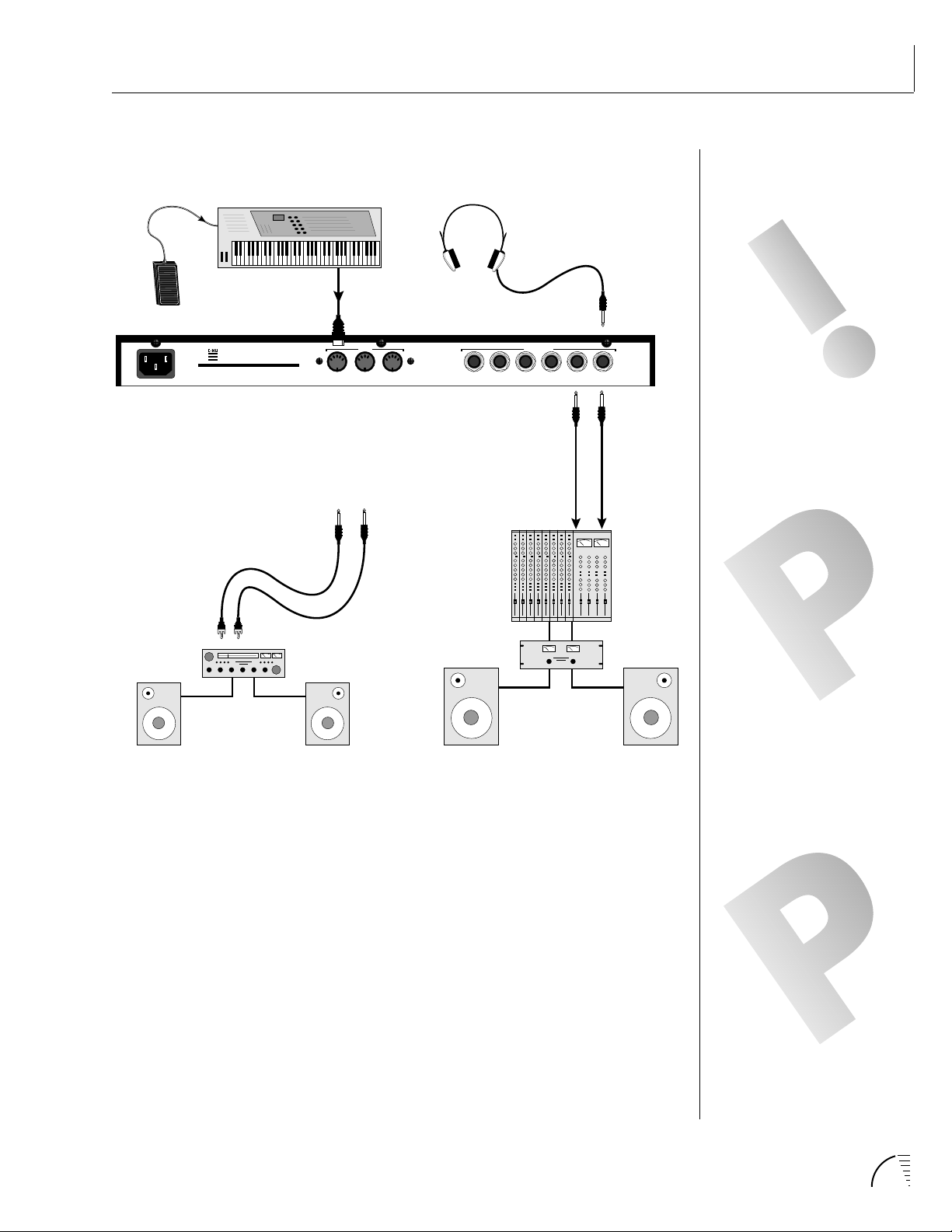
CONNECTION INSTRUCTIONS
SETUP #1 BASIC SETUP
The Headphone
Output is located
on the Front Panel
OUTPUTS
THRUOUTIN
R - SUB2 - L R - SUB1 - L R - MAIN - L
Mixer
Amp
MONO STEREO
Main Outs to Mixer In
THE HEADPHONE OUTPUT
MONITORS THE MAIN
OUTPUTS ONLY. THE SUBMIX
OUTPUTS DO NOT FEED INTO
THE HEADPHONE OUTPUT.
IF ULTRAPROTEUS DOES NOT
SEEM TO BE RESPONDING
CORRECTLY, MAKE SURE THAT
BOTH ULTRAPROTEUS AND YOUR
MIDI CONTROLLER ARE SET TO
THE SAME MIDI CHANNEL.
Speakers
Home Stereo
System
Home Studio
System
MIDI In
UltraProteus is controlled by MIDI messages received at the MIDI In connector.
Connect the MIDI In of the UltraProteus to the MIDI Out connector of a MIDI
controller such as a MIDI keyboard, MIDI wind controller or MIDI guitar
controller.
Audio Outputs
UltraProteus is a high quality, stereo audio device. In order to reproduce its
wide dynamic range and frequency response, use a high quality amplification
and speaker system such as a keyboard amplifier or home stereo system. A
stereo setup is highly desirable because of the added realism of stereophonic
sound. Headphones can be used if an amplifier and speaker system is not
available. Plug stereo headphones into the headphone jack located on the left
side of the front panel. The Right Main output jack serves as a mono output
when the Left Main plug is not plugged in. The Left Main output jack serves as a
stereo output when the Right Main plug is not plugged in.
MOST ULTRAPROTEUS FACTORY
PRESETS ARE PROGRAMMED TO
RESPOND TO PEDAL CONTROL.
SET YOUR KEYBOARD TO
TRANSMIT PEDAL ON
CONTROLLER #4, OR SEE “MIDI
REALTIME CONTROLLERS” IN THIS
MANUAL FOR ADDITIONAL
INFORMATION.
Chapter 1: Basic Setup 5
Page 15
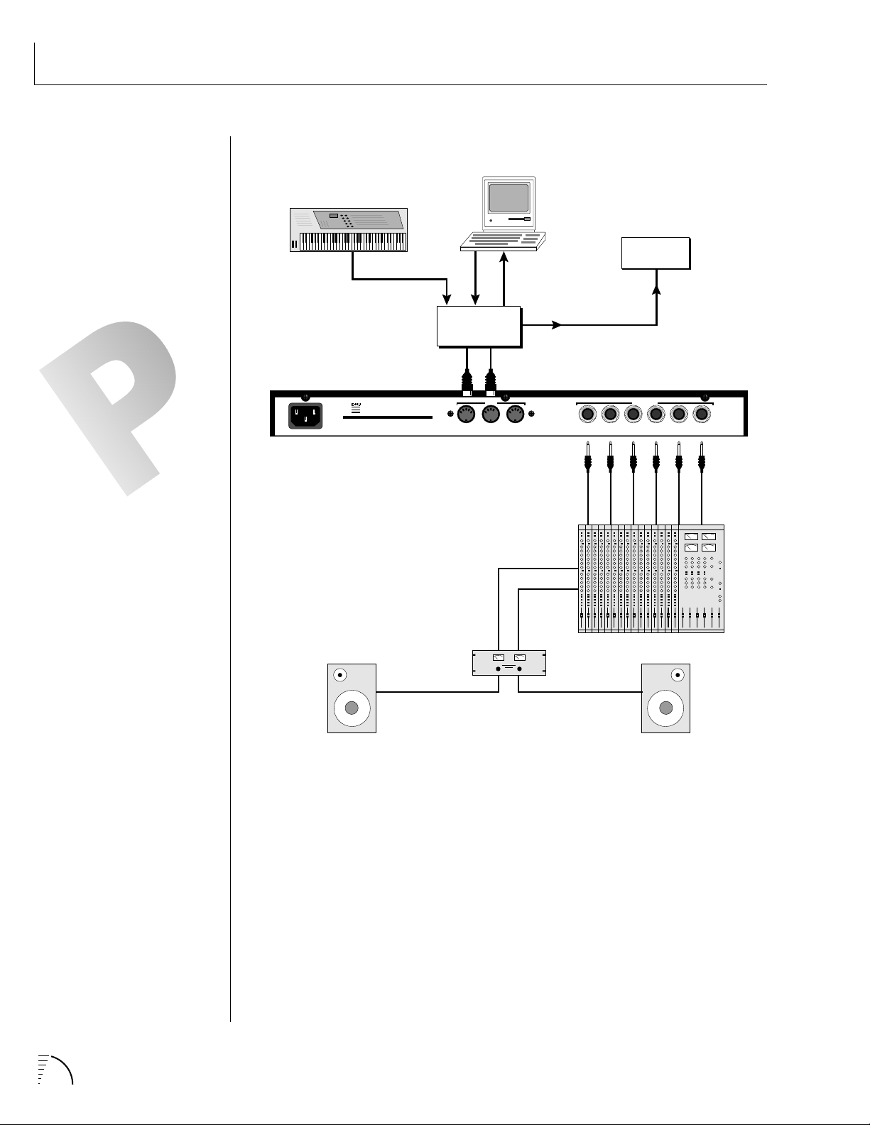
CONNECTION INSTRUCTIONS
SETUP #2 STUDIO SETUP
MANY OF THE ULTRAPROTEUS
FACTORY PRESETS HAVE BEEN
PROGRAMMED TO USE A FOOT
PEDAL CONTROLLER. TO USE
THIS EXCITING FEATURE, SET
YOUR MIDI CONTROLLER TO
TRANSMIT THE FOOTPEDAL ON
CONTINUOUS CONTROLLER
NUMBER 4. (This is the default
value, which can be be changed to
any controller number.)
MIDI Controller
(MIDI Keyboard, Sequencer, etc.)
MIDI Out
E-MU SYSTEMS, INC.
Scotts Valley, California U.S.A.
WARNING: TO REDUCE THE RISK OF FIRE
100-250VAC 50/60 Hz ~
OR ELECTRIC SHOCK, DO NOT EXPOSE
THIS PRODUCT TO RAIN OR MOISTURE.
MIDI
Out
MIDI Switcher
Out In
MIDI
OutInIn
THRUOUTIN
MIDI
In
Computer
Out
Additional
MIDI
Devices
MIDI In
OUTPUTS
R - SUB2 - L R - SUB1 - L R - MAIN - L
Effects-Only
MONO STEREO
Dry-Only
Main Outputs
MIDI In
In this setup, UltraProteus is controlled by MIDI messages received at the
MIDI In connector which have been routed by a MIDI switcher. The MIDI
switcher allows any MIDI controller such as a MIDI keyboard, MIDI wind
controller or a computer to be easily connected.
MIDI Out
The MIDI Out jack is normally used to transmit MIDI System Exclusive data to
a computer or other device.
Audio Outputs
UltraProteus has three sets of programmable stereo outputs; Main, Sub 1, and
Sub 2. Sub 1 is a non-effects output, Sub 2 is an effects-only output. Specific
UltraProteus presets (or MIDI channels) can be routed to one of these stereo
pairs in order to be further processed or mixed separately.
UltraProteus Operation Manual6
Page 16
CONNECTION INSTRUCTIONS
MIDI Controller
(MIDI Keyboard, Sequencer, etc.)
MIDI Out
E-MU SYSTEMS, INC.
Scotts Valley, California U.S.A.
WARNING: TO REDUCE THE RISK OF FIRE
100-250VAC 50/60 Hz ~
OR ELECTRIC SHOCK, DO NOT EXPOSE
THIS PRODUCT TO RAIN OR MOISTURE.
Sub Output
Return
(To Main Output)
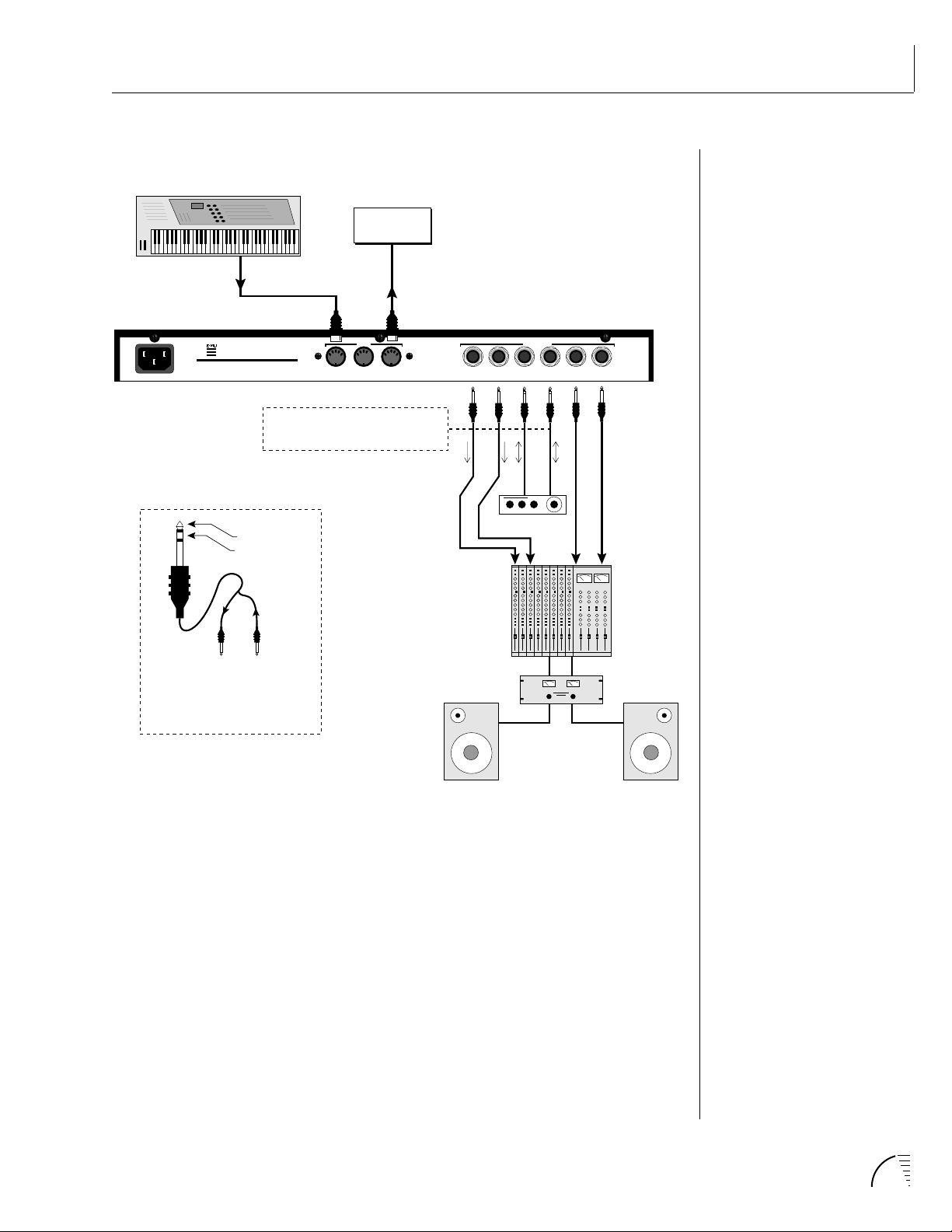
SETUP #3 PERFORMANCE SETUP
Additional
MIDI
Devices
MIDI In
MIDI
THRUOUTIN
Sub Outs 1 = NO Internal Effects
Sub Outs 2 = From Internal Effects
OUTPUTS
R - SUB2 - L R - SUB1 - L R - MAIN - L
Send
Effect Device
MONO STEREO
Send/Return
Main Outs to Mixer In
Tip Ring
To Effect From Effect
SEND/RETURN CABLE
Signal is sent out on tip of plug and
returned to main outputs via ring of plug.
MIDI In
UltraProteus is controlled by MIDI messages received at the MIDI In connector.
Connect the MIDI In of UltraProteus to the MIDI Out connector of a MIDI
controller such as a MIDI keyboard, MIDI wind controller or MIDI guitar
controller.
MIDI Thru
The MIDI Thru jack is used to connect additional MIDI devices onto the MIDI
chain. MIDI Thru transmits an exact copy of the messages received at the MIDI
In jack.
Audio Outputs
Each of the Sub 1 and Sub 2 output jacks on the UltraProteus are stereo jacks.
The tip of each jack (accessed when a standard phone plug is inserted) is the left
or right output of that group. If a stereo plug is inserted, the Ring of the stereo
plug serves as a signal Return which sums into the Main outputs. The Sub 1
outputs bypass the internal effects. Sub 2 are the outputs of the internal effects.
Chapter 1: Basic Setup 7
Page 17
CONNECTIONS
Therefore, the Sub 1 and Sub 2 jacks can serve as effect sends and returns in
order to further process selected instruments and then return them to the main
mix.
The diagram shows the Sub 1 and Sub 2 jacks being used as send/returns in
order to further process selected UltraProteus presets without using the effects
bus on the mixing board. In a pinch, the effect returns could also be used to
sum additional instruments into the main outputs.
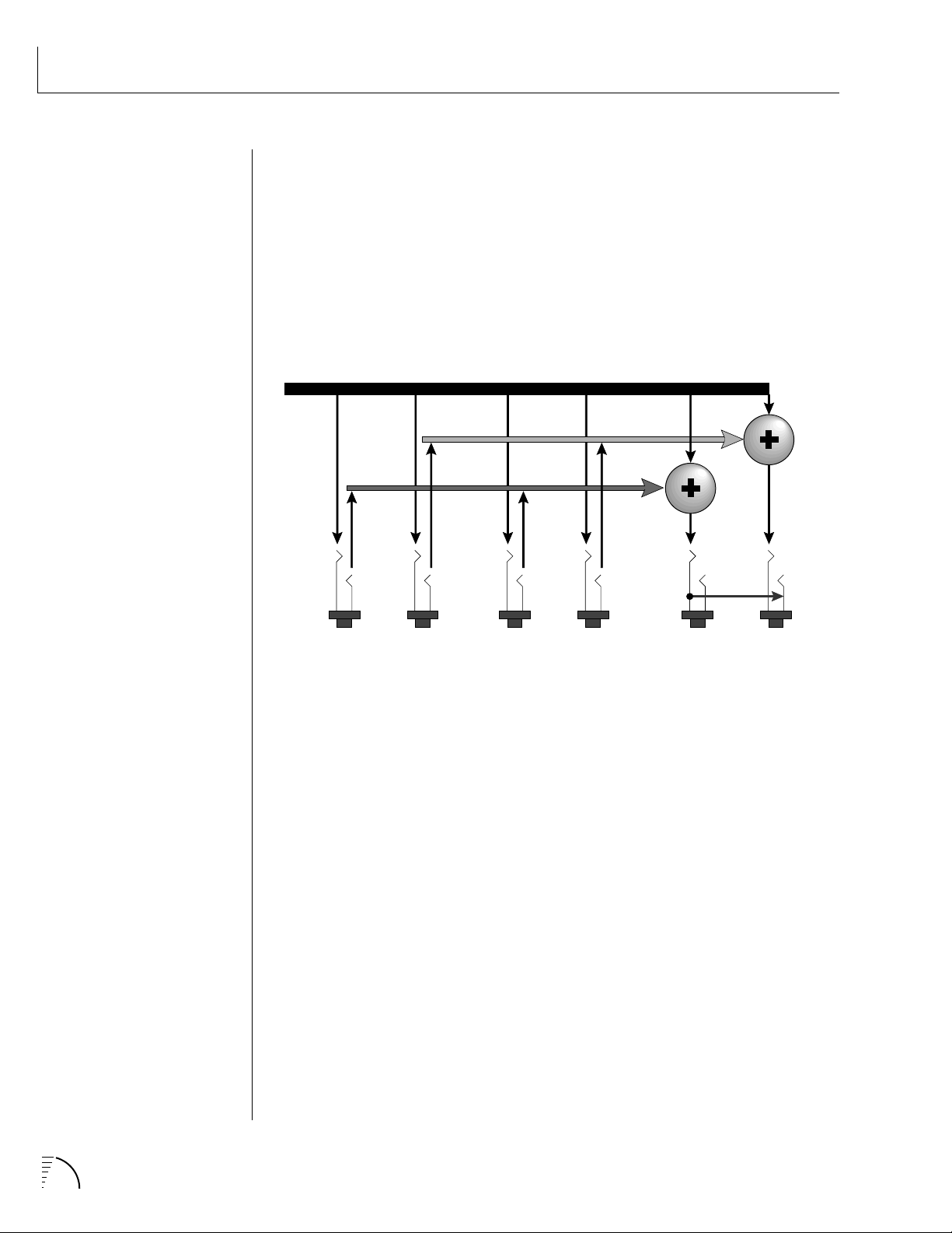
UltraProteus Output Section
L Bus
R Bus
Tip
RL RL RL
Ring
Tip
Ring
Tip
Ring
Tip
Ring
Tip Tip
Ring
SUB 2 SUB 1 MAIN
The Sub 1 and Sub 2 jacks can be used as effect returns to the Main Outputs.
POWER UP!
The power switch is located on the right side of the front panel. UltraProteus
and its MIDI controller may be turned on in any order. When power is applied,
the liquid crystal display will light, indicating that UltraProteus is operating.
You may have noticed that there is no 110/220 Volt power selector switch on
UltraProteus.
UltraProteus automatically switches itself for 110 or 220 Volt
operation.
UltraProteus Operation Manual8
Page 18
ABOUT SAMPLING
UltraProteus utilizes digital recording of acoustic sounds for the basis of each
Instrument. This is similar to a tape recorder except that inside the
UltraProteus, the sounds are permanently recorded on digital memory chips.
Sound and instrument waveforms are first sampled into the Emulator III, our
top of the line, 16 bit stereo digital sampler. After the sounds and waveforms
have been truncated, looped and processed, they are permanently encoded into
the UltraProteus ROM (Read Only Memory) chips.
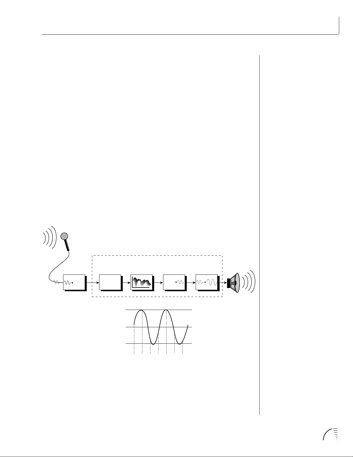
Conceptually, the sampling process is very simple, as shown in the Basic Sampling System diagram. As a sound wave strikes the diaphragm of a microphone,
a corresponding voltage is generated. To sample the sound, the voltage level is
repeatedly measured over time and the corresponding data values are stored in
memory. To play the sound back, the numbers are read back out of memory,
modified by the Z-plane filter, converted back into voltages, then amplified and
fed to a speaker which converts the voltage back into sound waves. Of course,
playing back 32 channels at different pitches tends to complicate matters, but
this is basically how it works.
BACKGROUND
Analog/Digital
Converter
1011001
Basic Sampling System
UltraProteus
Memory
10100101001
01010010100
10101010100
10101001010
3V
0V
-3V
Z-Plane Filter Amplifier
Digital/Analog
Converter
1011001
-1V -2V3V-1V-2V3V1V
Chapter 1: Basic Setup 9
Page 19

UltraProteus Operation Manual10
Page 20
UltraProteus BASIC OPERATION
11Chapter 2: Basic Operation
Page 21
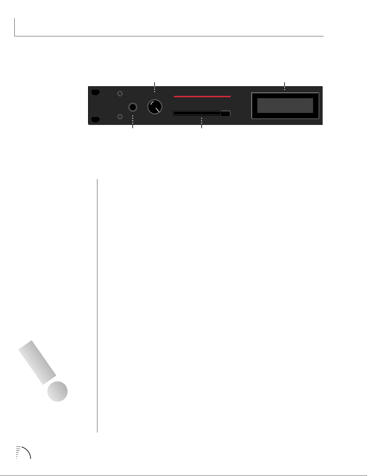
MAIN CONTROLS
VOLUME
CONTROL
DISPLAY
PHONES
HEADPHONE
JACK
VOLUME
UltraProteus
CARD
SLOT
C01 VOL127 PAN=P
1
021 Real:Z Piano
Volume Control
This is the master volume control for all audio outputs. Note: For maximum
dynamic range, set this control at full level.
Card Slot
The card slot accepts RAM and ROM cards containing additional presets,
hyperpresets and midimaps.
Master Menu Select Button
The Master menu contains global parameters which affect the entire machine.
The LED to the left of the button indicates that you are in the Master menu.
THE COMPARE FEATURE MUST
BE TURNED ON IN THE
MASTER MENU.
12 UltraProteus Operation Manual
Midimap Menu Select Button
A Midimap is a set of parameters used to configure UltraProteus to other MIDI
gear such as a sequencer or keyboard setup. The 16 Midimaps contain digital
effects setting as well as assignments of presets/hyperpresets to MIDI channels.
An LED to the left of the button indicates that you are working in the Midimap
menu.
Preset Menu Select Button
The Preset menu is used when you want to create or modify a preset. The LED
to the left of the button indicates that you are working in the Preset menu. To
Compare an edited preset with the unedited version, simply exit Preset Edit
mode. The stored preset will be heard whenever the main screen is selected.
Changing the preset will erase the edited version.
Hyperpreset Menu Select Button
The Hyperpreset menu is used to place presets at certain locations on the
keyboard to create custom keyboard layouts. The LED to the left of the button
indicates that you are working in the Hyperpreset menu.
Page 22
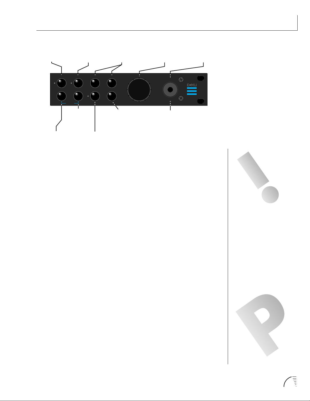
MAIN CONTROLS
MASTER
MENU
MIDIMAP
MENU
PRESET
PRESETMASTER
HYPERMIDIMAP COPY
DEMO
HYPER-
PRESET
MENU
MENU
<>
COPY
BUTTON
CURSOR
CONTROLS
CURSOR
HOME/ENTER
HOME/ENTER
BUTTON
DATA ENTRY
CONTROL
DATA
POWER
MIDI
MIDI
ACTIVITY
LED
POWER
SWITCH
Demo Sequence Select
UltraProteus contains two play-only sequences to demonstrate the range of
sounds. Press and hold the Midimap and the Hyperpreset buttons simultaneously
to select the Demo Sequence selection screen.
YOU MUST HOLD THE
MIDIMAP AND HYPERPRESET
BUTTONS FOR
APPROXIMATELY TWO
SECONDS TO START THE
DEMO SEQUENCES.
Cursor Control
These buttons move the cursor to the next parameter on the display in a clockwise or counter-clockwise direction. (The cursor is the little flashing line underneath one of the parameters in the display.) Press either cursor control button
repeatedly until the cursor is underneath the desired parameter.
Copy Button
The copy menu allows you to copy selected groups of parameters between
Presets, Hyperpresets, and Midimaps.
Home/Enter Button
The Home/Enter button is used to confirm a particular operation or to return
the cursor the “Home” position in the upper left corner (main screen-lower left).
The LED flashes to indicate that UltraProteus is waiting for your response.
Data Entry Control
The data entry control is a stepped, variable control which is used to change
parameter values. The control increments or decrements the current value one
unit with each click. This control incorporates acceleration (values advance
faster if the control is turned quickly).
Power Switch
Switches AC power to UltraProteus On and Off.
THE CURSOR CAN ALSO BE
MOVED BIDIRECTIONALLY USING
THE DATA ENTRY CONTROL
WHILE THE RIGHT CURSOR
BUTTON IS HELD DOWN. (I.E.
PRESS AND HOLD THE CURSOR
BUTTON AND TURN THE DATA
ENTRY KNOB.)
MIDI Activity LED
Indicates that MIDI data is being received.
13Chapter 2: Basic Operation
Page 23
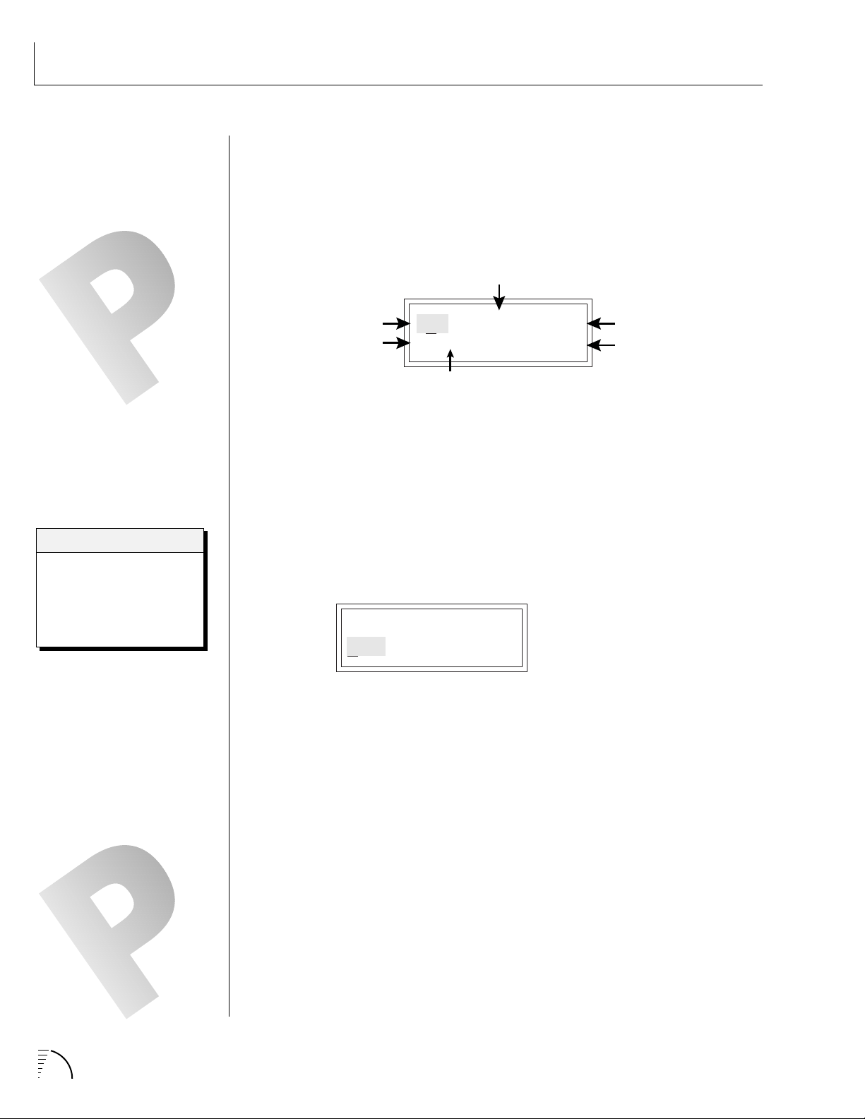
BASIC OPERATION
MIDI Channel
Program No.
Volume
Stereo Position
Program Name
Bank No.
IF ULTRAPROTEUS IS NOT
RESPONDING PROPERLY OR
PLAYS THE WRONG PRESET,
MAKE SURE THAT BOTH
ULTRAPROTEUS AND YOUR MIDI
CONTROLLER ARE SET TO THE
SAME MIDI CHANNEL AND THAT
THE MIDI VOLUME IS TURNED UP.
FOR MORE INFORMATION
ABOUT MIDI, SEE MIDI REALTIME
CONTROLS ON PAGE 97.
Bank Contents
-
RAM Presets
O
-
ROM Presets
1
-
RAM Hyperpresets
2
-
Card Presets
3
-
Card Hyperpresets
4
MIDI CHANNEL SELECTION
Press the cursor key repeatedly until the cursor is underneath the channel
number. (The cursor is the little flashing line underneath one of the parameters
in the display.) Rotate the data entry control to select MIDI channel 01-16. As
the channel is changed, the display will change to show the preset/hyperpreset,
volume and pan associated with the displayed channel.
C01 VOL127 PAN=P
0
000 Preset Name
PRESET/HYPERPRESET (PROGRAM) SELECTION
Press the cursor key repeatedly (or press Home/Enter) until the cursor is
underneath the program number. A Program is a Preset or a Hyperpreset. As
the data entry control is rotated, the program number and name will change.
The displayed program will be assigned to the displayed MIDI channel. Programs are arranged into banks of 128, as shown in the diagram at left. Banks
can be selected independently of the program number by pressing the Home/
Enter button while turning the data entry knob.
C01 VOL127 PAN=P
0
000 Program Name
÷ MIDI Channel Parameters
÷ Preset/Hyperpreset Name
CHANNEL PAN SHOULD
NORMALLY BE SET TO “P”
UNLESS REALTIME CONTROL OF
PANNING IS DESIRED. IF PAN IS
SET TO “0”, STEREO EFFECTS
CREATED IN THE PRESET WILL BE
LOST.
14 UltraProteus Operation Manual
CHANNEL VOLUME
Press the cursor key repeatedly until the cursor is underneath the volume value.
Rotate the data entry control to select volume 000-127. (This is the same
parameter as MIDI volume control #7, and changes made over MIDI will be
shown in the display.)
CHANNEL PAN
Press the cursor key repeatedly until the cursor is underneath the pan value.
Rotate the data entry control to select pan values -7 to +7 or “P”. When “P” is
selected, the pan value specified in the preset is selected. Any other value will
override the pan parameter in the preset. (This is the same parameter as MIDI
pan control #10, and changes made over MIDI will be shown in the display.)
Page 24
BASIC OPERATION
MEMORY CARD
The memory card is a convenient method of saving and transferring presets and
hyperpresets. Insert the card firmly into the slot on the front panel with the
label facing up. Press the eject button to release the card. A RAM card stores 128
presets, 128 hyperpresets and 16 midimaps. RAM cards may be Write-Protected
by moving the little switch on the end of the card. If a memory card is NOT
inserted, the display reads “ --noCard-- ” for banks 3 & 4 and the list of selectable midimaps shrinks to 16.
MIDIMAP SELECTION
A Midimap is a set of parameters which can be used as a pre-sequence setup,
storing the program and other parameters for each MIDI channel or it could be
used as an “Effects Preset”, since each Midimap stores a complete effects setup.
There are 16 Midimaps in UltraProteus and an additional 16 Midimaps can be
stored on a memory card.
To Select a Midimap
Press the Midimap key, lighting the LED. The current screen will be the
one most recently selected since powering up UltraProteus. The first
screen in the menu is Midimap Select. Move the cursor to the lower line
and use the data entry control to select one of the 16 Midimaps. The
Home/Enter LED will be flashing. Press the Home/Enter key to load the
new Midimap.
RAM CARDS CAN BE USED TO
STORE YOUR OWN PRESETS,
HYPERPRESETS AND MIDIMAPS.
ROM CARDS CONTAIN
PRE-RECORDED PRESETS,
HYPERPRESETS AND MIDIMAPS.
YOU CANNOT SAVE DATA TO A
ROM CARD.
RAM CARDS NEED TO BE
INITIALIZED BEFORE THEY
ARE FIRST USED. THEY
DISPLAY WILL PROMPT YOU
TO INITIALIZE A BLANK
CARD.
MIDIMAP SELECT
M00 -defMIDIMap-
MIDIMAP
16 Channels
MIDI CHANNEL 1
PROGRAM
VOLUME
PAN
MIDI
ENABLES
BANK
SELECT
Simply scrolling through the list DOES NOT change the Midimap. You must
move the cursor down to line two and press Enter. Try out the different
Midimaps and notice that the effects change with each one.
MIX
SELECT
Main
Sub 1
FX A
FX B
EFFECT
A
EFFECT
B
A
O
M
U
O
T
U
P
N
U
T
T
THE “CURRENT MIDIMAP” IS
REMEMBERED ON POWERDOWN, EVEN THOUGH YOU
MAY NOT HAVE SAVED IT. THIS
EFFECTIVELY GIVES YOU A TOTAL
OF 17 INTERNAL MIDIMAPS.
15Chapter 2: Basic Operation
Page 25

BASIC OPERATION
MULTI-TIMBRAL OPERATION
Multi-timbral operation means that the UltraProteus can play more than one
sound at the same time. To access multiple presets on different MIDI channels
simultaneously, follow these instructions:
1. Set the MIDI mode to MULTI-Mode, using the MIDI mode function in the
Master menu (page 22).
2. Decide which MIDI channels you wish the UltraProteus to receive, and
turn “All Messages” Off for the MIDI channels that you DO NOT want
UltraProteus to receive using the MIDI Enables in the Midimap menu
(page 33). Turning “All Messages Off” turns that channel Off.
If you do not turn any channels Off, UltraProteus will receive all 16
MIDI channels simultaneously!
3. Select the desired preset or hyperpreset for each of the MIDI channels you
wish the UltraProteus to receive using the Preset/Hyperpreset -> MIDI
Channel selection screen in the Midimap menu (page 31).
4. Save the Midimap using the last screen in the Midimap menu.
5. UltraProteus will now respond multi-timbrally on the MIDI channels you
have specified.
6. The effects can be programmed and each MIDI channel assigned to an
effects bus if so desired. The volume and pan position can be adjusted for
each MIDI channel in the Midimap Volume and Pan screen. Remember to
SAVE the Midimap or all of your work will be LOST when you select
another Midimap.
PLAYING THE DEMO SEQUENCES
UltraProteus contains a play-only sequencer with 2 different sequences to give
you an idea of what is possible using this amazing instrument. Press and hold
both the Midimap and Hyper buttons. The sequence will start momentarily.
Press the Enter button to stop the sequence. Press the right cursor button to
advance to the next sequence. Sequences will cycle automatically.
16 UltraProteus Operation Manual
DEMO 1 2
ENTER=Stop >=Nxt
Page 26
UltraProteus MASTER MENU
Page 27

18 UltraProteus Operation Manual
Page 28

The Master menu contains functions that affect the overall operation of
UltraProteus. For example, changing the Master Tune will change the tuning of
all the presets, not just the one currently displayed.
To enable the Master menu
Press the Master button, lighting the LED. The current screen will be the
one most recently selected since powering up UltraProteus. The Cursor
will appear underneath the first character of the screen heading on line
one.
To select a new screen
Press the Home/Enter button or press the Cursor key repeatedly until the
cursor is underneath the screen title heading. Rotate the data entry
control to select another screen.
To modify a parameter
Press the Cursor button repeatedly (or hold the right cursor key while
turning the data entry control) until the cursor is underneath the parameter value. Rotate the data entry control to change the value.
MASTER MENU
To return to the main screen
Press the Master button, turning off the LED.
MASTER MENU FUNCTIONS
Master Tune
Master Tune adjusts the overall tuning of all presets so that UltraProteus can be
tuned to other instruments. The master tuning range is ± 1 semitone in 1/64th
semitone increments. A master tune setting of “+00” would indicate that the
UltraProteus is perfectly tuned to concert pitch (A=440 Hz).
MASTER TUNE
+63
Transpose
This function transposes the key of UltraProteus in half-step intervals. The
transpose range is ± 12 semitones or one octave.
TRANSPOSE
+12 semitones
19Chapter 3: Master Menu
Page 29
MASTER MENU
APPLICATION: THE USER KEY
TUNING CAN BE USED TO TUNE
INDIVIDUAL PERCUSSION
INSTRUMENTS.
IT IS POSSIBLE TO TUNE THE
PITCH UP SO HIGH THAT THE
RANGE OF ULTRAPROTEUS'
PITCH SHIFTER IS EXCEEDED.
IF THE PITCH WILL NOT GO
ANY HIGHER, TRY USING THE
TRANSPOSE CONTROL
INSTEAD OF COARSE
TUNING.
User Key Tuning
In addition to standard twelve tone equal temperament, UltraProteus contains
four additional preset tuning tables (Just C, Vallotti, 19 tone, and Gamelan) and
one user definable tuning. User Key Tuning allows you to alter the parameters
of the user definable tuning stored in memory. The initial frequency of every
key can be individually tuned, facilitating the creation of microtonal scales.
Using the cursor key and the data entry control, select the key name, the MIDI
key number and the fine tuning. The key name is variable from C-2 to G8.
Coarse Tuning (which also happens to be the MIDI key number) is variable
from 0 to 127. The fine tuning is variable from 00 to 63 in increments of 1/64 of
a semitone (approx. 1.56 cents). For each preset, the specific tuning table is
selected in the Preset menu.
USER KEY TUNING
Key Name
Key:C1 036-00
Fine Tuning
Coarse Tuning
Global Bend
This function sets the range of the pitch wheel controller only when Pitch
Wheel is routed to control pitch . The maximum pitch bend range is ± 12
semitones. This function only affects presets which have their individual pitch
bend range set to global.
IN ORDER FOR THE PITCH WHEEL
TO CONTROL PITCH, IT MUST BE
ROUTED TO THIS DESTINATION
IN THE REALTIME MODULATION
CONTROL SCREEN.
ALSO: THE AMOUNT PARAMETER
IN THE MODULATION SCREEN
WILL HAVE NO EFFECT WHEN
THE PITCH WHEEL IS USED TO
CONTROL PITCH.
GLOBAL BEND
±12 semitones
Global Velocity Curve
Incoming velocity data can be modified by a velocity curve in order to provide
different types of dynamics in response to your playing or to better adapt to a
MIDI controller. This function allows you to select one of eight global velocity
curves or leave the velocity data unaltered (off). Global velocity curve only
affects presets which have their individual velocity curve set to global.
GLOBAL VEL CURVE
8
20 UltraProteus Operation Manual
Page 30
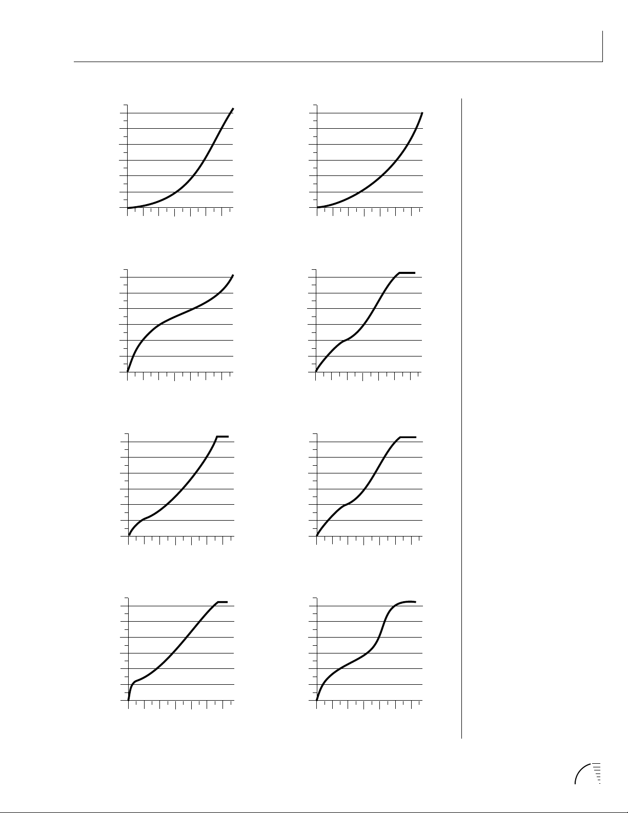
GLOBAL VELOCITY CURVES
MASTER MENU
120
100
80
60
40
Result Velocity
20
0
Curve 1
20
0
Played Velocity
120
100
80
60
40
Result Velocity
20
0
20
0
Played Velocity
120
100
80
60
40
Result Velocity
20
40
100
120
80
60
Curve 2
0
20
0
40
60
120
100
80
Played Velocity
120
100
80
Curve 3
40
100
120
80
60
60
40
Result Velocity
20
0
20
0
40
Curve 4
120
100
80
60
Played Velocity
120
100
80
60
40
Result Velocity
20
0
20
0
Played Velocity
120
100
80
60
40
Result Velocity
20
0
20
0
Played Velocity
120
100
80
Curve 5
40
100
120
80
60
60
40
Result Velocity
20
0
20
0
Curve 6
40
100
120
80
60
Played Velocity
120
100
80
Curve 7
40
60
120
100
80
60
40
Result Velocity
20
0
20
0
Curve 8
40
60
120
100
80
Played Velocity
21Chapter 3: Master Menu
Page 31

MASTER MENU
MONO MODE FUNCTIONS THE
SAME WAY AS SOLO “WIND”
MODE.
MIDI Mode
This function selects one of the four MIDI receive modes and the MIDI system
exclusive ID number.
Omni mode
UltraProteus responds to note information on all MIDI channels and plays
the preset currently displayed in the main screen.
Poly mode
UltraProteus only responds to note information received on the currently
selected MIDI channel (the “basic channel”, displayed on the main screen)
and plays that channel’s associated preset.
Multi mode
UltraProteus responds to data on any combination of MIDI channels and
plays the specific preset associated with each of the MIDI channels.
Mono mode
UltraProteus responds to data on any combination of MIDI channels but
plays each channel monophonically. If a new note on a channel is played
before the last note is released, the envelopes will not be retriggered. Mono
mode is particularly useful with alternate controllers such as MIDI guitars,
etc.
Device ID
This function allows an external programming unit to distinguish between
multiple UltraProteus units. In the case of multiple UltraProteus units,
each unit should have a different device ID number.
WARNING: MIDI SYSEX DATA
WILL NOT BE TRANSFERRED
BETWEEN TWO
ULTRAPROTEUS UNITS
UNLESS THE ID NUMBERS OF
BOTH UNITS MATCH.
MIDI MODE ID
Omni 00
MIDI Mode Change
This function selects whether or not MIDI mode change commands are accepted or ignored when received over MIDI (see MIDI Mode).
MIDI MODE CHANGE
Disabled
22 UltraProteus Operation Manual
Page 32

MIDI Program Change Map
Incoming MIDI program changes can be remapped to a different numbered
preset. This is a handy feature when you want a specific MIDI program number
sent from the master synth to be linked with a specific preset or hyperpreset on
UltraProteus. For example, the Program Change Map could be set to call up
preset 12 whenever UltraProteus receives program change number 26. Any
preset or hyperpreset in UltraProteus can be mapped to any incoming MIDI
program change number. There are four separate Program Change Maps
available. This feature also allows you to call up presets in any bank, which are
not accessible through a standard MIDI program change. Note: The Program
Map only operates if it is selected in the Midimap and if the Bank Select function in the Midimap is set to bank 0.
PROG CHG MAP #1
026 > 012
0
MASTER MENU
THE BANK SELECT FUNCTION IS
LOCATED IN THE MIDIMAP
MENU.
0 1 2 3 4 5 6 7 8 9
00 01 02 03 04 05 06 07 08 09
44 191 50 01 15 88 151 78 320 88
10
Selected
Program
34 73 106 55 43 75 120 121 511
20
30 31 32 33 34 35 36 37 38 39
30
40 41 42 43 44 45 46 47 48 49
40
50 51 52 53 54 55 56 57 58 59
50
60 61 62 63 64 65 66 67 68 69
60
70 71 72 73 74 75 76 77 78 79
70
80 81 82 83 84 85 86 87 88 89
80
90 91 92 93 94 95 96 97 98 99
90
100 101 102 103 104 105 106 107 108 109
100
110 111 112 113 114 115 116 117 118 119
110
120
120 121 122 123 124 125 126 127
12
Mapped
Program
This chart shows how MIDI preset changes can be re-mapped. In this example,
program changes 10-29 have been re-mapped. All other programs will be selected
normally.
23Chapter 3: Master Menu
Page 33

MASTER MENU
A FEW OF THE
STANDARDIZED MIDI
CONTROLLER NUMBERS ARE
LISTED BELOW.
1 - MODULATION WHEEL OR
LEVER
2 - BREATH CONTROLLER
3 - AFTERTOUCH: REV 1 DX7
4 - FOOT PEDAL
5 - PORTAMENTO TIME
6 - DATA ENTRY
7 - VOLUME
8 - BALANCE
9 - UNDEFINED
10 - PAN
11 - EXPRESSION
MIDI Controller Assign
UltraProteus allows you to assign up to four realtime control sources from your
MIDI controller. These control sources could be modulation wheels, data sliders
or whatever. In this screen, you set up which controllers will be received by the
UltraProteus. What effect the controller will have is programmed separately for
each preset. The UltraProteus MIDI controllers are each assigned a letter, A-D.
Each controller letter can be assigned to a MIDI realtime controller from 00-31.
Note: If controller numbers 7 or 10 are selected, they will override the standard
MIDI volume and pan control routings. For more information, see MIDI
Realtime Controls in the Programming Basics section.
CONTROLLER# ABCD
01 02 03 04
MIDI Footswitch Control
Like the MIDI Controllers, 3 MIDI footswitches can be assigned to MIDI footswitch numbers. Footswitches can be assigned numbers from 64-79. Destinations for the footswitch controllers are programmed in the Preset menu.
A FEW OF THE
STANDARDIZED MIDI SWITCH
NUMBERS ARE LISTED
BELOW.
64 - SUSTAIN SWITCH (ON/OFF)
65 - PORTAMENTO (ON/OFF)
66 - SOSTENUTO (ON/OFF)
67 - SOFT PEDAL (ON/OFF)
69 - HOLD PEDAL 2 (ON/OFF)
WARNING: WHEN
TRANSFERRING SYSEX DATA
FROM ONE ULTRAPROTEUS
TO ANOTHER, THE ID
NUMBERS OF BOTH UNITS
MUST MATCH.
FOOTSW CTL# 123
64 65 66
Send MIDI Data
This function will send MIDI System Exclusive data to the MIDI Out port of
UltraProteus. The MIDI data can either be sent to a computer/sequencer or to
another UltraProteus. Using the cursor key and the data entry control, select
the type of MIDI data you wish to transmit.
SEND MIDI DATA
RAM Presets
The Enter LED will be flashing. Press the Enter button to confirm the operation. To receive MIDI data, simply send the MIDI data into UltraProteus from
another UltraProteus or your sequencer. The choices are listed on the following
page:
24 UltraProteus Operation Manual
Page 34

MASTER MENU
RAM Presets............................................ Transmits all the user RAM presets.
ROM Presets ...................................... Transmits all the factory ROM presets.
Card Presets ...................................... Transmits all the memory card presets.
RAM Hypers .................................. Transmits all the user RAM hyperpresets.
Card Hypers............................ Transmits all the memory card hyperpresets.
RAM MIDI Maps......................................... Transmits all the user MIDI maps.
Card MIDI Maps ........................Transmits all the memory card MIDI maps.
Program Change Maps..................Transmits all the program change maps.
Master Settings .....................Transmits all parameters in the Master menu
except tuning table, program change map & viewing angle.
The “scratch” Midimap is also transmitted.
Tuning Table ......................................... Transmits only the user tuning table.
All RAM Data.................... Transmits all the user RAM data in the machine.
Individual Program ..... Transmits only the specified preset or hyperpreset.
Individual Midimap ............................ Transmits only the specified midimap.
TO RECORD MIDI DATA
INTO A SEQUENCER:
1. SETUP SEQUENCER TO
RECEIVE SYSTEM EXCLUSIVE
DATA.
2. PLACE SEQUENCER INTO
RECORD MODE, THEN SEND
MIDI DATA.
TO RECEIVE MIDI DATA
FROM A SEQUENCER:
1. SIMPLY PLAY BACK THE
SEQUENCE INTO
ULTRAPROTEUS.
WARNING: SEND DATA
FROM YOUR SEQUENCER
AS YOU WOULD A
REGULAR SEQUENCE.
SENDING DATA IN ONE
HUGE CHUNK MAY CLOG
THE ULTRAPROTEUS INPUT
BUFFER.
Individual Program Change Map ......Transmits the specified program map.
When Individual Programs, Midimaps or Program Change Maps are received via
SysEx, they are placed in their proper locations.
Sysex Packet Delay
Errors can sometimes occur when transferring Sysex data from UltraProteus to
a computer because the computer cannot process and store the incoming data
fast enough. This function allows you to change the amount of delay between
MIDI Sysex data packets so that the input buffer of your computer does not
overflow. The default speed is 300 delay units. A setting of “000” allows full
speed MIDI Sysex. If you are having data transmission errors, increase the delay
until the problem disappears.
SYSEX PKT DELAY
300
A MIDIMAP RECEIVED BY
ULTRAPROTEUS DOES NOT
CHANGE THE “SCRATCH”
MIDIMAP UNLESS IT IS
CURRENTLY SELECTED. YOU
MUST SELECT THE MIDIMAP
FOR IT TO BE ACTIVE. SEE
PAGE 159.
THE INDIVIDUAL MIDIMAPS AND
PROGRAM CHANGE MAPS ARE
LOCATED AFTER THE INDIVIDUAL
PROGRAMS (KEEP SCROLLING).
TURN “KEYBOARD THRU”
MODE OFF ON YOUR
SEQUENCER WHEN
TRANSFERRING SYSEX DATA
OR A MIDI FEEDBACK LOOP
MAY RESULT.
25Chapter 3: Master Menu
Page 35

MASTER MENU
Proteus Sysex
When this function is turned On, Proteus presets can be transferred over MIDI
into UltraProteus. It also allows the use of Proteus patch editing programs.
Instrument numbers will be translated into UltraProteus equivalents. Parameters which are unique to UltraProteus will, of course, NOT be transferred. This
function defaults to Off to avoid unplanned conflicts with Proteus Sysex transfers.
PROTEUS SYSEX
Off
Auto Select
When editing a parameter which involves the keyboard, such as a zone range,
the parameter can be automatically selected simply by playing the keyboard.
This is a handy feature for “power programmers”, but can sometimes be confusing. Therefore, Auto-Select can be turned On or Off. Auto-Select affects the
following parameters: User Key Tuning, Zone Select, Key Range, Midimap,
Preset & Hyperpreset Naming, Cross-switch Point, Keyboard Center.
IF ULTRAPROTEUS DOES NOT
RESPOND TO EXTERNAL
PRESET EDITORS, TURN THE
COMPARE FUNCTION OFF.
AUTO-SELECT
Off
Compare
This function turns the Compare feature (accessed by pressing the Preset
button when editing) On or Off. If Compare is turned On, changes made via
MIDI SysEx will not be heard except when the Preset menu is enabled.
COMPARE
On
Viewing Angle
This function allows you to change the viewing angle of the display so that it
may be easily read from either above or below. The angle is adjustable from +7
to -8. Positive values will make the display easier to read when viewed from
above. Negative values make the display easier to read from below.
VIEWING ANGLE
+7
26 UltraProteus Operation Manual
Page 36

UltraProteus MIDIMAP MENU
27Chapter 4: Midimap Menu
Page 37

28 UltraProteus Operation Manual
Page 38

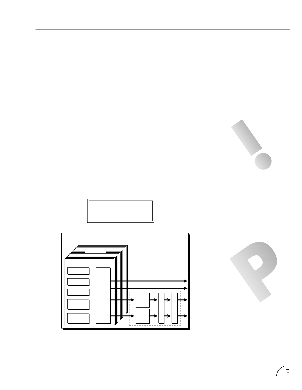
THE MIDIMAP
A Midimap is a group of parameters which you might associate with a specific
sequence or song. You can also use the Midimaps as “Effects Presets” for your
favorite effects setups. The Midimap contains all the pre-sequence setup information, such as the program (preset or hyperpreset) for each MIDI channel,
effects settings, etc. There are 16 Midimaps in UltraProteus and an additional 16
can be stored on a memory card.
MIDIMAP
16 Channels
MIDI CHANNEL 1
MIDIMAP MENU
PROGRAM
VOLUME
PAN
MIDI
ENABLES
BANK
SELECT
MIX
SELECT
Main
Sub 1
FX A
FX B
EFFECT
A
EFFECT
B
O
A
M
O
N
U
T
U
T
P
U
T
Midimaps are often used with UltraProteus connected to an external
sequencer in MULTI mode. Multi mode allows UltraProteus to receive MIDI data
on all 16 channels simultaneously. UltraProteus can store 16 different
Midimaps. The two digital effects processors are also part of the Midimap.
MIDI Map
MIDI Map Name
Program
Volume
Pan
Mix Select
MIDI Enables
Bank Select
12 Characters
for 16 MIDI Channels
for 16 MIDI Channels
for 16 MIDI Channels
for 16 MIDI Channels
for 16 MIDI Channels
for 16 MIDI Channels
MIDIMAPS CAN ALSO BE
CHANGED USING A SYSEX
PARAMETER CHANGE
COMMAND. SEE PAGE 159.
Program Change Map
Effect A
Effect B
Effect Amount
Effect Output Select
Off, 1-4
Effect Select & Parameters
Effect Select & Parameters
Wet/Dry Mix, A->B Amount
Main, Sub 1, Sub 2
29Chapter 4: Midimap Menu
Page 39

MIDIMAP MENU
SELECTING A NEW MIDIMAP
WILL OVERWRITE THE
“CURRENT” OR “SCRATCH”
MIDIMAP.
To enable the Midimap menu
Press the Midimap button, lighting the LED. The current screen will be
the one most recently selected since powering up UltraProteus. The cursor
will appear underneath the first character of the screen heading on line
one.
To select a Midimap
Press the Home/Enter button or press the cursor key repeatedly until the
cursor is underneath the screen title heading. The first screen in the list is
“Midimap Select”. Move the cursor to the lower line of the display and use
the data entry control to select the desired Midimap. The Home/Enter LED
will be flashing. Press Home/Enter to load the Midimap.
To select a new screen
Press the Home/Enter button or press the cursor key repeatedly until the
cursor is underneath the screen title heading. Rotate the data entry
control to select another screen.
To modify a parameter
Press the cursor button repeatedly (or hold the cursor key while turning
the data entry control) until the cursor is underneath the parameter value.
Rotate the data entry control to change the value.
To return to Program Select mode
Press the Midimap button, turning off the LED.
MIDIMAP MENU FUNCTIONS
Midimap Select
This is where you select one of the 16 Midimaps. You can use the Midimaps to
setup a particular sequence or song. Position the cursor under the Midimap
number and use the data entry control to select the Midimap. The Home/Enter
LED will be flashing. You MUST press Enter to load the Midimap.
MIDIMAP SELECT
M00 Cool FX
30 UltraProteus Operation Manual
Page 40

Midimap Name
This function allows you to name each of the 16 Midimaps with a name of up to
12 characters. Position the cursor underneath the character location and use
the data entry control to change the character. The keyboard can also be used to
select characters.
This screen displays the current Midimap. The Midimap Select screen is the last
screen in the menu.
MIDIMAP NAME
M15 New Song
Preset/Hyper to MIDI Channel Assign
This function allows you to assign a preset or hyperpreset (program) to each
MIDI channel for the currently selected Midimap.
Position the cursor under the channel number and use the data entry control to
change the MIDI channel. Position the cursor under the program number and
use the data entry control to change the program assigned to each MIDI channel.
MIDIMAP MENU
THE AUTO-SELECT FEATURE IN
THE MASTER MENU MUST BE
TURNED ON IN ORDER TO
USE THE KEYBOARD FOR
NAMING MIDIMAPS.
Preset/Hyperpreset No.
Assigned to MIDI Channel
PRESET/HYPER C01
0
061 Space Wash
MIDI Channel
Volume, Pan & Output Mix
This function sets the Volume, Pan Position and Output Mix for each MIDI
channel in the selected Midimap. Volume allows you to adjust the relative
volume between programs. Pan allows you to position each program in the
stereo field. The Volume control acts as an attenuator on the program volume.
It cannot increase the volume past the setting programmed in the program.
▼ The Pan control Overrides the pan value programmed in the program.
Volume
for MIDI Channel
Stereo Pan Position
for MIDI Channel
VOL PAN MIX C01
127 =P FxA
MIDI Channel
Output Mix Select
for MIDI Channel
THE MIDI CHANNEL SHOWN
IN THE RIGHT SIDE OF THE
SCREEN IS NOT THE MIDI
BASIC CHANNEL, ONLY THE
ONE BEING EDITED IN THE
MIDIMAP.
CHANNEL PAN SHOULD
NORMALLY BE SET TO “P”
UNLESS REALTIME CONTROL OF
PANNING IS DESIRED. IF PAN IS
SET TO “0”, STEREO EFFECTS
CREATED IN THE PRESET WILL BE
LOST.
31Chapter 4: Midimap Menu
Page 41

MIDIMAP MENU
The Output Mix allows you to selectively route the program through one of the
effects processors or direct it to a pair of output jacks (for each of the 16 MIDI
channels). An additional selection called Preset or “P”, allows the selection to be
made in the preset (Mix Output). Thus effects and outputs can be selected
according to MIDI channel or by preset.
Position the cursor under the channel number and use the data entry control to
change the MIDI channel. Position the cursor under the volume, pan or mix
and use the data entry control to change the value. The volume and pan values
are the same ones shown in the main screen.
The diagram below shows the function of Output Mix Select.
PLEASE NOTE THAT THE SUB 2
OUTPUT IS AN “EFFECTS ONLY”
OUTPUT.
MIDI Channel 1
MIDI Channel 2
MIDI Channel 3
MIDI Channel 16
Preset
= FXA
Mix
Select
M
A
I
N
S
U
B
F
X
A
Output
Select
OUTPUT SECTION
& EFFECTS PROCESSORS
M
A
I
N
S
U
B
1
FXA
S
U
B
2
The Output Mix Select (for each MIDI channel) selects which bus in the Output Section
will be used.
32 UltraProteus Operation Manual
F
X
B
FXB
Page 42

MIDI Enables
The MIDI enables allow you to enable or filter out specific MIDI messages on a
per-channel basis. MIDI messages that can be filtered include:
MIDIMAP MENU
All Messages
Program Change
Bank Select
Volume Control
Pan Control
The “All Messages” filter is useful when you have other MIDI devices connected
and do not want UltraProteus to respond to the MIDI channels reserved for
other devices. Messages will be passed when On and filtered out when turned
Off.
(turns channel off)
(controller #7)
(controller #10)
Pitch Wheel
Mono Pressure
Key Pressure
Controllers A-D
Footswitches 1-3
MIDI ENABLES C01
AllMessages On
Bank Select
The MIDI specification only allows for 128 presets per MIDI channel. This
function selects which bank of 128 presets will be used for incoming MIDI
program change commands. Banks can be set for each MIDI channel. This
function allows you to access all presets and hyperpresets in UltraProteus
without using a MIDI Bank Select command.
THE CHANNEL PAN CONTROL
CAN BE DISABLED TO PREVENT
INCOMING MIDI MESSAGES
FROM ALTERING STEREO
EFFECTS PROGRAMMED IN THE
PRESETS.
BANK SELECT C01
0
MIDI Chan. Bank# Type
Channel 1 Bank 0 RAM Presets
Channel 2 Bank 2 RAM Hyperpresets
Channel 3 Bank 1 ROM Presets
Channel 16 Bank 0 RAM Presets
33Chapter 4: Midimap Menu
Page 43

MIDIMAP MENU
THE PROGRAM CHANGE MAPS
ARE LOCATED IN THE MASTER
MENU.
Program Map Select
There are four Program Maps in UltraProteus. Program Maps allow incoming
MIDI program changes to be translated into another number. For example, a
program map could be set up so that program number 12 is selected whenever
program change number 26 is received at the MIDI in port. The Program Map
Select function allows you to select one of the four Program Maps to be used in
the currently selected Midimap or turn the Program Map function Off. Note:
The Program Map only operates if it is turned On and the Bank Select function
is set to bank 0.
PROG CHG MAP
Off
0 1 2 3 4 5 6 7 8 9
00 01 02 03 04 05 06 07 08 09
44 191 50 01 15 88 151 78 320 88
10
12
Mapped
Program
Selected
Program
34 73 106 55 43 75 120 121 511
20
30 31 32 33 34 35 36 37 38 39
30
40 41 42 43 44 45 46 47 48 49
40
50 51 52 53 54 55 56 57 58 59
50
60 61 62 63 64 65 66 67 68 69
60
70 71 72 73 74 75 76 77 78 79
70
80 81 82 83 84 85 86 87 88 89
80
90 91 92 93 94 95 96 97 98 99
90
100 101 102 103 104 105 106 107 108 109
100
110 111 112 113 114 115 116 117 118 119
110
120
120 121 122 123 124 125 126 127
This chart shows how MIDI preset changes can be re-mapped. In this example program
changes 10-29 (darkened area) have been re-mapped. All other programs will be
selected normally.
FX A
This function allows you to select which effect is active on Effect Processor A.
Processor A effects include several types of reverb as well as other effects such as
delays, chorus, flanger, and phase shifter. Each effect has one or more adjustable parameters which are accessed by moving the cursor to the lower line. See
the Effects section for detailed information on these functions.
34 UltraProteus Operation Manual
FXA: Room
Decay Time 100
Page 44

FX B
This function allows you to select which effect is active on Effect
Processor B. Processor B effects include echo, delay, chorus, phase shifter,
distortion and ring modulator. Each effect has one or more adjustable parameters which are accessed by moving the cursor to the lower line. See the Effects
section for detailed information on these functions.
FXB:StereoFlange
LFO Rate 050
FX Amount
This function allows you to adjust the ratio of dry (unprocessed) to wet (processed) signal coming out of the effect processor. A setting of 100% indicates
that all of the signal is being processed by the effect. The B->A parameter allows
you to adjust the amount of effect B which will be fed through the A effect.
If B->A is set to one value above 100%, the word “Only” is displayed and the B
amount changes to Off. This disconnects effect B from the main outputs and
routes ALL of effect B through effect A.
MIDIMAP MENU
FX AMOUNT A:50%
B->A:0% B:75%
EFFECTS AMOUNT
sum
A
B
FXA
B ➞ A
Amount
FXB
IF THE B->A AMOUNT IS SET
TO “ONLY”, NO SOUND
WILL RESULT IF “NO
EFFECT” IS SELECTED FOR
EFFECT A
sum
Wet/Dry Mix
sum
Wet/Dry Mix
35Chapter 4: Midimap Menu
Page 45

MIDIMAP MENU
FX Output Select
This function selects which pair of output jacks each effect processor will be
routed. This is shown in the diagram on page 32 by the 3-way switches after
each effect processor.
FX OUTPUT SELECT
A:Main B:Sub 1
Save Midimap
Changes made to a Midimap are not made permanent until the Midimap is
Saved. To save a Midimap, move the cursor to the bottom line and select one of
the 16 locations with the data entry control. The Enter LED will be flashing.
Pressing the Home/Enter switch will confirm the operation. Writing to a
Midimap location erases the existing Midimap in that location. Make sure that
the location does not contain information you want to keep.
Save MIDIMAP to
M00 -defMIDIMap-
36 UltraProteus Operation Manual
Page 46

UltraProteus EFFECTS SECTION
37Chapter 5: Effects Section
Page 47

38 UltraProteus Operation Manual
Page 48

Where are the Effects?
The effects in UltraProteus are separate from the preset. This is similar to an
external effects unit except that the signal path is kept in the digital domain to
maintain excellent sound quality.
MIDIMAP
FX SETTINGS
Effect
Preset
The Effects section in UltraProteus is located external to the preset in the Midimap
menu.
A
Effect
B
EFFECTS SECTION
The effects section is located within the Midimap. There are 16 Midimaps (and
16 more on a memory card) which store different effects setups. You could
think of a Midimap as an Effects Preset (although they store other parameters as
well).
MIDIMAP 00
16 MIDI Channels
MIDI
Channel
01
FX
Main
Sub1
A
B
Preset
FX SETTINGS
Effect
A
Effect
B
16
For each of the 16 MIDI channels, you may select: Effect A, Effect B, the Main
Outputs (with no effect), the Sub 1 Output (with no effect), or you may choose
to use the Mix Select programmed as part of the preset. Therefore you can select
effects routings by MIDI channel or by preset. The choice is up to you.
39Chapter 5: Effects Section
Page 49

EFFECTS SECTION
EFFECTS OUTPUT ROUTING
The diagram below shows how the effects section is integrated into the output
jack routing scheme. The mix bus can be selected either by the preset or by
MIDI channel. When “Preset” is selected, the MIX SELECT programmed in the
preset is used.
MIDI Channel 1
MIDI Channel 2
MIDI Channel 3
MIDI Channel 16
Preset
= FXA
Mix
Select
M
A
I
N
S
U
B
F
X
A
F
X
B
Output
Select
OUTPUT SECTION
& EFFECTS PROCESSORS
M
A
I
N
S
U
B
1
FXA
S
U
B
2
FXB
ULTRAPROTEUS EFFECT BUS ARCHITECTURE
The two stereo effect processors on UltraProteus are designated as A and B
effects. “A” effects contain Reverb and other effects. The “B” effects do not
include Reverbs, but include a host of other great effects which are listed on
page 53.
Each effect has its own set of control parameters which are appropriate to that
particular effect. For both the A and B effects there is an amount parameter
which determines the relative mix of the processed and unprocessed signals
(wet/dry mix). The output of the B effect can also be routed back through
processor A. In addition, the stereo submix outputs (Sub 1) can be used to
externally process selected presets.
40 UltraProteus Operation Manual
Page 50

TO PROGRAM AN EFFECT:
1) Press the MIDIMAP button lighting the LED.
2) Slowly turn the data entry knob clockwise until you find the screen shown
below. Select one of the effect processors in the Mix Selection. This selects
the input to the effect processors.
EFFECTS SECTION
VOL PAN MIX C01
127 =P FXA
3) Set the FX Amount for the A or B effect. This adjusts the ratio of effected to
un-effected signal. B->A allows you to route the output of effect B through
effect A (set the MIX to effect B).
FX AMOUNT A:50%
B->A:0% B:50%
EFFECTS AMOUNT
sum
FXA
B ➞ A
FXB
Wet/Dry Mix
sum
Wet/Dry Mix
sum
A
Amount
B
THE DIAGRAM ON THE PREVIOUS
PAGE ILLUSTRATES THE
FUNCTION OF MIX SELECT.
SETTING THE B->A PERCENTAGE
TO MAXIMUM SELECTS “ONLY”
WHICH DISCONNECTS EFFECT B
FROM THE MAIN OUTPUTS AND
ROUTES ALL OF THE SIGNAL
THROUGH EFFECT A.
IF THE B->A AMOUNT IS SET
TO “ONLY”, NO SOUND
WILL RESULT IF “NO
EFFECT” IS SELECTED FOR
EFFECT A
4) Select the desired Effect and program the appropriate parameters.
FXA:Echo
L Delay Time 255
5) Set the FX Output if you want to use the Sub 1 or Sub 2 outputs.
41Chapter 5: Effects Section
Page 51

EFFECTS SECTION
A EFFECTS
Room
Warm Room
Small Rooms 1 & 2
Halls 1, 2 & 3
Chambers 1 & 2
Plates 1 & 2
Early Reflections 1-4
Reverse Early Refl.
B EFFECTS
Fuzz
Fuzz Lite
Stereo Flange
Phaser
Stereo Chorus
Delay
Cross Delay
Ring Modulator
Rain & Shimmer
Stereo Flange
Phaser
Stereo Chorus
Delay
Cross Delay
Echo
REVERB
Reverberation is a simulation of a natural space such as a room or hall. The
reverb effects in UltraProteus simulate various halls, chambers, rooms and
reverberation plates. In addition, there are several other reverb effects such as
Early Reflections and Rain. There is only one adjustable parameter on the
reverbs - Decay Time. Decay time is the length of time that it takes for the
reflected sound from the walls of the room to die away. In general, the larger
the room, the longer the decay time.
The diagram below breaks down the reverberated sound into its component
parts. After an initial pre-delay period, the echoes from the closest walls or
ceiling are heard. These first echoes or the early reflection cluster, vary greatly
depending on the type of room. Roughly 20 milliseconds after the reflection
cluster, the actual reverberation begins and decays according to the time set by
the decay time parameter.
AMPLITUDE
Pre
Delay
42 UltraProteus Operation Manual
Cluster
Floor, Wall &. Ceiling
Reflections
ReverbReflex
TIME
Decay Time
Thousands of
Very Complex
Reflections
Page 52

Room programs simulate small rooms with high frequency absorption caused
by drapes and furniture.
Plates simulate plate type reverbs with their tight, dense early reflections and
sharp reverb build-up.
Chambers simulate medium sized rooms with hard reflective surfaces.
Hall programs recreate the open, spacious ambience of large concert halls.
Early Reflection programs consist of the reflection cluster only without the
reverb decay. These effects are similar to a multiple tap delay line and have a
single adjustable parameter - Ambience.
The special reverbs Rain & Shimmer are variations of the early reflection
programs and consist of a dense group of short echoes followed by longer
echoes.
FXA:Hall 1
Decay Time: 165
EFFECTS SECTION
Place the cursor underneath the reverb name and use the data entry control to
change the type of reverb. Moving the cursor to the lower line allows you to
change the decay time of the reverb. The decay times of the reverb programs
range from 10-255. The ambience control of the Early Reflection programs
range from 0-100.
Room
A bright, medium sized room. The apparent source position is fairly close to the
listener. Suitable for use with 100% wet mix setting for adding ambience.
Warm Room
This reverb is similar to “Room” with more high frequency absorption, slightly
larger size and a more distant source position.
Small Room 1
This reverb is also to “Room” with shorter initial reflections, shorter decay
times and higher reflection density, due to the reduced room size. The apparent
source position is closer to the listener.
Small Room 2
This reverb is a variation of “Small Room 1” with greater high frequency damping and a more distant source position.
Hall 1
Hall 1 is a large, highly reverberant space with auditorium-like acoustics. Like
all the Hall programs, “Hall 1” exhibits a warm, distant ambience with slow
reflection density buildup. With the decay parameter set to maximum, “infinite”
reverberation effects can be obtained. Adjustment of wet-dry mix can be used to
position the listener from the “front row” (≈25%) to “back of the balcony”
(≈100%).
43Chapter 5: Effects Section
Page 53

EFFECTS SECTION
Hall 2
This reverb is similar to “Hall 1”, but harder and brighter, with more pronounced slap echoes that come from parallel reflecting surfaces in the room.
Hall 2 also exhibits a pronounced reverb “bloom” or late-reflection buildup. A
50% wet mix creates the optimum “close” distance adjustment.
Hall 3
Hall 3 is similar to “Hall 2”, but with larger scale stadium-like acoustics. Hall 3
is warmer than Hall 2 (more high frequency damping) and does not display the
obvious early reflections and slap echoes. It also exhibits a distinct predelay of
approximately 100 milliseconds and a pronounced late reflection buildup both
of which contribute to the impression of a large space. Wet mix values of 10% to
50% are most appropriate, although a setting of 100% produces an effective
cave simulation.
Chamber 1
A simulation of a bright, medium-sized chamber reverb or recital hall with hard
walls. Early reflections are very prominent, with high reflection density. Moderately long decays are possible at the maximum decay setting.
Chamber 2
Similar to “Chamber 1” but with a much warmer sound. The wet mix adjustment provides an effective control over the apparent source location from close
(10%) to very distant (100%).
Plate 1
Simulates a plate reverb unit. Gives a tight, bright, slightly metallic sound.
Reflection buildup is very rapid, with high density. Early reflections are minimized.
Plate 2
An effect similar to Plate 1, but slightly warmer with less density.
44 UltraProteus Operation Manual
Page 54

EARLY REFLECTION GROUP
All Early Reflection programs have a single Ambience parameter which adds
diffusion to the individual reflections. Lower ambience settings cause reflections to become more discrete, simulating harder reflecting surfaces. The early
reflection programs are simulations of increasingly large acoustic spaces, from a
small studio (Early Refl 1) to a large room like a sound stage (Early Refl 4). The
wet mix control acts effectively as source distance control. In general, lower mix
amounts are more effective as the room size increases.
Early Reflection 1
Early Reflection 2
Early Reflection 3
Early Reflection 4
Reverse Early Reflection
More of a special effect than an acoustic simulation, Reverse ER contains a set
of exponentially increasing delay taps, creating a kind of “zip” sound at low
Ambience settings. At maximum ambience and lower wet mix values, the sound
is more authentically acoustic, with a long, delayed reflection “bloom”. The
effect is similar to a large but well damped parking garage.
EFFECTS SECTION
SPECIAL REVERBS
These special reverbs all have a single Decay Time parameter.
Rain
Similar to a repeating delay, but with complex spatial and filtering effects
occurring across the stereo panorama. The effect on percussive sounds might be
likened to a bucket of marbles raining down on a galvanized steel roof.
Shimmer
Distantly related to the Rain effect, Shimmer causes input signals to be progressively diffused in time and space across the stereo panorama. The spatial diffusion is accompanied by a flanging effect. The program is highly responsive to
left or right-panned inputs. A stunning special effect with percussive sounds,
and especially through headphones.
45Chapter 5: Effects Section
Page 55

EFFECTS SECTION
Stereo Flanger
A flanger consists of a short audio delay line whose output is mixed together
with the original signal. Mixing the delayed and original signals together results
in multiple frequency cancellations creating a comb filter effect as shown in the
diagram below. Since the flanger is a type of filter, it works best with harmonically rich sounds such as strings.
AMPLITUDE (dB)
FREQUENCY (log)
The flanging effect was originally created using two tape recorders playing
identical recordings. By exactly synchronizing the two decks and then slowing
the speed of one by grasping the tape reel flanges, the flanging effect was born.
The flanger in the UltraProteus is a stereo device consisting of two separate
delay lines controlled by a single set of controls. The block diagram of the
flanger is shown below.
R Input
Feedback
Amount
L Input
+-
Delay
0-6.5 mS
Delay
0-6.5 mS
R Output
L Output
46 UltraProteus Operation Manual
Minimum
Delay
LFO
Rate
LFO
Depth
LFO
Page 56

A Minimum Delay control serves to tune the flanger. In other words, it adjusts
the placement of the comb filter notches. The initial delay is variable from 26
microseconds to 6.5 milliseconds.
FXA:StereoFlange
Min Delay 100
A Low Frequency Oscillator (LFO) varies this initial delay setting, changing
the frequency of the notches and adding animation to the sound. The LFO Rate
controls the rate of change and the LFO Depth controls how much the delay is
changed by the LFO. The LFO adds to the initial delay time so that with LFO
Depth set to 255 the maximum delay time is 13 milliseconds.
FXA:StereoFlange
LFO Rate 038
EFFECTS SECTION
FXA:StereoFlange
LFO Depth 150
The Feedback control sends some of the delayed signal through the delay line
again. When positive feedback is used (values +1 to +127), the comb filter
notches are deepened; when negative feedback is used (values -1 to -127)
resonant peaks are formed between the notches which increase with the
amount of negative feedback.
FXA:StereoFlange
Feedback -127
47Chapter 5: Effects Section
Page 57

EFFECTS SECTION
Stereo Phaser
The stereo phaser is an effect similar to the flanger although much more subtle.
The phaser creates a swirly animation when used with harmonically rich sounds
such as strings and voices. It can also be used like a chorus to thicken-up a thin
sound.
R Input
Feedback
Amount
L Input
+-
Minimum
Freq.
LFO
Rate
Phase
Shifter
Phase
Shifter
LFO
R Output
L Output
LFO
Depth
FXA:Phaser
LFO Rate 060
FXA:Phaser
Min Freq 015
48 UltraProteus Operation Manual
FXA:Phaser
LFO Depth 100
FXA:Phaser
Feedback 064
Page 58

Stereo Chorus
The function of a chorus device is to thicken the sound or to make one voice
sound like many. The way the effect is achieved is by mixing one or more
delayed versions of the signal in with the original. The delay times used are too
short to be perceived as a an echo, but long enough so that comb filtering does
not occur. In addition, the delay time is varied to simulate the random differences which occur when multiple instruments are playing together. A slight
amount of feedback improves the effect by creating multiple images of the
sound as it recirculates again and again. The delay times are slightly different
for each channel and the LFO phase is inverted on the right channel to help
contribute to the overall chorus effect. The LFO Rate and Depth settings are
critical to achieving a realistic effect with faster LFO Rates generally requiring
less LFO Amount and vice-versa.
The stereo chorus in the UltraProteus is very similar to the stereo flanger except
that the delay time is longer. The delay times for the stereo chorus range from
13 milliseconds to 52 milliseconds, compared with the 26 microsecond to 6.5
millisecond range of the flanger.
EFFECTS SECTION
R Input
Feedback
Amount
+-
L Input
Minimum
Delay
LFO
Rate
Chorus simulates the effect of multiple instruments playing by creating multiple
copies of the sound using a varying delay time and feedback.
Delay
13-52 mS
Delay
13-52 mS
LFO
R Output
L Output
LFO
Depth
49Chapter 5: Effects Section
Page 59

EFFECTS SECTION
FXA:StereoChorus
LFO Rate 050
FXA:StereoChorus
LFO Depth 050
FXA:StereoChorus
Min Delay 036
FXA:StereoChorus
Feedback +100
Delay
The delay line is a stereo effect which can be used for doubling, echoes or fixed
formant comb filtering with completely independent delay time and tap levels
for the left and right sides. The delay is shown in the diagram below.
Right
Delay
Right
Tap Level
R Input
Feedback
Amount
+-
L Input
The Delay Time parameter is independently variable from 0 to 209 milliseconds
for both the left and right channels. The Tap Level parameters control the
amount of signal from the left and right delays as well as how much signal from
each is supplied to the feedback control. Feedback controls how many echoes
are produced. A setting of 0 produces only one echo. The delay line is incredibly
Left
Delay
Delay
Delay
Left
Tap Level
R Output
L Output
50 UltraProteus Operation Manual
Page 60

stable even with large amounts of feedback. This quality allows the delay line to
be used as a resonator, where it acts as a kind of oscillator when excited by an
input signal. Infinite delay effects are also possible without the risk of runaway.
The stereo delay can function as two independent delay lines by panning the
primary and secondary instruments to the extreme left and right.
EFFECTS SECTION
FXA:Delay
L DelayTime 060
FXA:Delay
L Tap Level 120
FXA:Delay
R DelayTime 120
FXA:Delay
R Tap Level 120
FXA:Delay
Feedback 255
Cross Delay
Cross Delay is identical to the normal delay line except that the output paths
and the feedback paths cross over to the opposite channel in order to produce a
ping-pong type of effect when reproduced in stereo. Delay time is adjustable
from 0 to 209 milliseconds. The Cross Delay is shown in the diagram below.
R Input
Feedback
Amount
L Input
Right
Delay
+-
Left
Delay
Delay
Delay
Right
Tap Level
R Output
L Output
Left
Tap Level
51Chapter 5: Effects Section
Page 61

EFFECTS SECTION
Echo
The Echo produces echoes up to 400 milliseconds in length (twice that of the
Delay and Cross Delay effects). The feedback path is independent of the output
level and contains a low pass filter which simulates an analog tape echo. The left
and right signals are kept completely independent throughout the effect and
have separate controls except the feedback amount control which affects both
channels.
R Input
Feedback
Amount
L Input
Right
Delay
+-
Left
Delay
Delay
Delay
Low
Pass
Low
Pass
Right
Tap Level
R Output
L Output
Left
Tap Level
FXA:Echo
L DelayTime 120
FXA:Echo
L Tap Level 127
52 UltraProteus Operation Manual
FXA:Echo
R DelayTime 100
FXA:Echo
R Tap Level 127
FXA:Echo
Feedback 100
Page 62

B EFFECTS
The B effects include Stereo Flanger, Stereo Chorus, Phaser, Fuzz, Ring Modulator, Delay, Cross Delay and Fuzz Lite. Some of the B effects such as the Fuzz
and the Ring Modulator are a bit bizarre (you won't want to use them on every
sound), but can be used to create some truly amazing effects. The B effects can
additionally be routed through the A effect as shown in the diagram below.
Simple effects such as Fuzz can take on a completely new character when
routed through the Reverb.
EFFECTS AMOUNT
sum
sum
A
FXA
Wet/Dry Mix
EFFECTS SECTION
B ➞ A
Amount
B
FXB
sum
Wet/Dry Mix
Stereo Delay B
The B Delay is identical to the delay line in the A effect group except that the
maximum delay time is 104 milliseconds (instead of 209 milliseconds). This
delay is useful for short echoes, slapback and doubling effects, as well as for
fixed formant comb filtering. Like Stereo Delay A, the feedback parameter is
extremely stable even with high amounts, making it useful as a resonator for
“infinite” delays.
Stereo Cross Delay B
The B Cross Delay is identical to the cross delay line in the A effect group except
that the maximum delay time is 104 milliseconds (instead of 209 ms). This
delay is useful for short ping-pong echoes, stereo slapback and doubling effects.
53Chapter 5: Effects Section
Page 63

EFFECTS SECTION
STEREO FUZZ
The Stereo Fuzz introduces a controlled distortion to any signal passing
through it. Distortion creates harmonics by clipping the top of the wave when it
exceeds a certain level. Sine waves are transformed into square waves and
complex waves take on noise-like qualities. There are two types of fuzz in
UltraProteus: Fuzz and Fuzz Lite.
Fuzz
This Fuzz is probably the grungiest fuzz you have ever heard. Two filters, one at
the input and one at the output of the fuzz, allow you to control the amount
and type of harmonics added to the sound. The Input Filter controls the
amount of harmonics produced by the fuzz and the Output Filter removes
harmonics at the output, smoothing the sound. Higher values allow more
harmonics to pass. The level of the input sound greatly affects the amount of
fuzz, so that UltraProteus' envelopes can now control harmonic content as well
as the volume. Output Volume sets the output level of the fuzz. There are two
complete fuzz effects, controlled by the same set of controls as shown in the
diagram below.
L Input
Input
Filter
(LowPass) (LowPass)
Input
Filter
(LowPass) (LowPass)
Fuzz
Fuzz
Output
Filter
Output
Filter
Output
Volume
Output
Volume
R OutputR Input
L Output
Two independent sounds can be processed by panning primary and secondary to
opposite sides, or a single sound can be routed through both sides. If a single
sound is panned slightly off center, the fuzz will act slightly differently on each
side because of the difference in level.
Fuzz Lite
This is a more restrained type of fuzz utilizing “soft-clipping”. As the level
increases, the waveform through Fuzz Lite becomes somewhat squared. As
signal level is increased further, it transforms into a square wave. There is no
Output Volume control on Fuzz Lite.
Fuzz
Experiment with the way the input and output filters work on the sound. Fuzz
is a specialized effect, not for every situation, but another powerful tool in your
arsenal.
54 UltraProteus Operation Manual
Lite
Page 64

Ring Modulator
A Ring Modulator is a device which takes two signals and multiplies them
together into one resultant signal containing only the sum and difference
frequencies of the two input waves. The original frequencies are not output!
However, every harmonic of each signal multiplies every other, according to its
amplitude. As a result, ring modulators tend to generate a lot of non-harmonic
frequencies which can sound very bell-like or out of tune.
Left
(pri)
200 Hz
AMPLITUDE
200
FREQUENCY (Hz)
EFFECTS SECTION
Right
(sec)
800 Hz
AMPLITUDE
800
FREQUENCY (Hz)
Result
600 &
1000 Hz
This diagram shows the result of Ring Modulating two sine waves with frequencies of
200 Hz and 800 Hz. Only the Sum and Difference frequencies of 1000 Hz and 600 Hz
will result.
AMPLITUDE
200 600 800 1000
FREQUENCY (Hz)
55Chapter 5: Effects Section
Page 65

EFFECTS SECTION
R
L
R Output
L Output
Ring
Modulator
Pan
R
Pri
DCA
Pan
L
Sec
DCA
There are no controls on the ring modulator as shown by the block diagram
below. The left and right outputs are simply multiplied together to form a
monophonic output.
Ring
Modulator
R Input
L Input
By routing the preset (or MIDI channel) to effect B and panning to opposite
sides (shown below), two different waves can be ring modulated. Ring modulation works well with simple waves such as sine waves and the harmonic waveforms. Also, try complex waves modulated with sine waves. (Play chords!)
Complex waveforms tend to sound rather noise-like.
R Output
L Output
Pan the primary and secondary instruments to left and right in the pan screen,
then move to the Effect B screen and select Ring Modulator. There are no
parameters to adjust in this effect so the lower line of the display reads: None.
56 UltraProteus Operation Manual
FXB:RingModulate
None ---
Page 66

UltraProteus HYPERPRESET MENU
57Chapter 6: Hyperpreset Menu
Page 67

58 UltraProteus Operation Manual
Page 68

THE HYPERPRESET
A Hyperpreset is a group of one to sixteen presets which have been assigned to
areas of the keyboard in order to have more than one sound available at once.
Presets are assigned to ranges of the keyboard called Zones and may include 1key
or all 128 keys. Zones may be placed adjacent to each other (to create a split
keyboard) or may overlap (to create fat, layered sounds). Each zone has its own
volume, pan, transpose, tuning and velocity range.
(3 Zones) (Zone) (Zone) (Zone)
Preset
Presets Placed
Preset- Layer -
Presets Assigned
to the same
Keyboard Range
Preset
Preset
Preset
Preset
- Keyboard Split -
Adjacent to Each Other
HYPERPRESET MENU
AN ADDITIONAL 128
HYPERPRESETS CAN BE STORED
ON A MEMORY CARD.
Up to sixteen presets can be assigned to the keyboard in any desired arrangement
To enable the Hyperpreset menu
Press the Hyper button, lighting the LED. The current screen will be the
one most recently selected since powering up UltraProteus.
The Hyperpreset to be edited will be the LAST one selected or edited. The
cursor will appear underneath the first character of the screen heading on
line one.
To select a new screen
Press the Home/Enter button or press a cursor button repeatedly until the
cursor is underneath the screen title heading. Rotate the data entry
control to select another screen.
To modify a parameter
Press the Cursor button repeatedly (or hold the right cursor button while
turning the data entry control) until the cursor is underneath the parameter value. Rotate the data entry control to change the value.
To compare an edited Hyperpreset with the unedited original
Press the Hyper button, turning off the LED. The unedited Hyper is now
active. Changing the Hyperpreset number will erase the edit. To hear the
edited hyperpreset again, press the Hyper button, lighting the LED.
IN ORDER TO HEAR THE
HYPERPRESET AS YOU EDIT
IT, YOU MUST HAVE IT
ASSIGNED TO A MIDI
CHANNEL IN THE MAIN
SCREEN.
COMPARE MODE MUST BE
TURNED ON IN THE MASTER
MENU FOR THE COMPARE
FEATURE TO WORK.
To return to the main screen
Press the Hyper button, turning off the LED.
59Chapter 6: Hyperpreset Menu
Page 69

HYPERPRESET MENU
HYPERPRESET MENU FUNCTIONS
Hyperpreset Name
Hyperpreset Name allows you to name each of the 128 hyperpresets with a
name of up to 12 characters. Position the cursor under the character location
and use the data entry control to change the character. The keyboard can also
be used to select characters. The chart below shows the keyboard character
assignments.
HYPERPRESET NAME
2
000 Bass/Lead
IF THE AUTO-SELECT
FUNCTION (IN THE MASTER
MENU) IS TURNED ON,
ZONES WILL BE SELECTED AS
THE KEYBOARD IS PLAYED. IN
THE CASE OF OVERLAPPING
ZONES, THE LOWEST ZONE
NUMBER WILL BE SELECTED.
VELOCITY WILL SELECT THE
ZONE IF VELOCITY
SWITCHING HAS BEEN
PROGRAMMED.
%
(
#
!
&
b
l
a
n
k
+
"
'
$
)
4
/
-
0
,
.
9
5
2
7
3
8
6
1
*
;=@
:
<
B
?
D
A
>
C
GIL
E
F
N
Q
J
O
K
H
P
M
SUX
T
R
Z
Y
V
[
W
¥
_ad
]
^
f
c
h
`
e
b
g
kmp
i
j
r
n
s
o
l
t
q
wy|
u
v
->
x
}
z
<-
{
Preset to Zone Assignment
This function allows you to select the preset which will be assigned to each of
the sixteen keyboard zones. Position the cursor under the zone number and use
the data entry control to change the zone number. Position the cursor under
the preset number and use the data entry control to change the preset associated with each zone. Any preset can be assigned to a zone. Set the preset number of unused zones to Off (located below preset 000).
PRESET Z01
0
003 Multi/Split
60 UltraProteus Operation Manual
Page 70

Zone Volume and Pan
This function sets the Volume and Pan position for each zone. Volume allows
you to adjust the relative volume between presets and pan allows you to change
the position of each zone in the stereo field. The Volume control acts as an
attenuator on the preset volume. It cannot increase the volume past the setting
programmed in the preset. The Pan control adds algebraically to the pan value
programmed in the preset. Therefore if the preset pan setting is -7, (full left) a
hyperpreset pan setting of +14 would move the sound to (+7) the extreme right
side of the stereo field.
Position the cursor under the zone number and use the data entry control to
change the zone number. Position the cursor under the volume or pan number
and use the data entry control to change the value for each zone.
VOLUME PAN Z01
127 +00
HYPERPRESET MENU
Zone Key Range
Key range sets the keyboard range associated with each of the sixteen possible
zones. The key range of each zone can be set anywhere from key C-2 to G8.
UltraProteus Keyboard Range
MIDI
Key #
Key
Name
By placing the key ranges next to each other on the keyboard, multiple instruments can be accessed simultaneously. This is called “splitting” the keyboard
because the keyboard is literally split up into different sections each containing
a different sound.
If multiple presets are placed on the same range of the keyboard, they will all be
played simultaneously. This is called “layering” since multiple presets are
layered on top of one another. This results in a very dense, “fat” sound.
0 12 24 36 48 60 72 84 96 108 120 127
C-2 C-1 C0 C1 C2 C3 C4 C5 C6 C7 C8
= Standard 5 Octave Keyboard Range
KEY RANGE Z01
C-2 -> G8
61Chapter 6: Hyperpreset Menu
Page 71

HYPERPRESET MENU
Key Range
Zone 1
Zone 2
Preset #1
Preset #2
LAYERING TWO PRESETS
Zone #1
Key Range
Zone #2
Key Range
CREATING A SPLIT KEYBOARD
Zone Velocity Range
Each zone can be given its own velocity range so that different presets will be
selected according to the keyboard velocity. Imagine two presets assigned to the
same keyboard range. If one preset were assigned the velocity range 000 to 64,
and the other to velocity range 65 to 127, key velocities below 65 would select
the first preset and key velocities 65 and above would select the second preset.
Because there are sixteen possible zones, presets can be layered 16 deep!
High Velocities
Play this Preset
Low Velocities
Play this Preset
Zone Velocity Range allows you to select different preset layers according to key
velocity.
62 UltraProteus Operation Manual
VEL RANGE Z01
low:000 hi:127
Preset
Preset
(Velocity Range 065-127)
(Velocity Range 001-064)
Page 72

Zone Velocity Offset
This function works in conjunction with the Zone Velocity Range feature and
adds a programmable offset value to the velocity value applied to the preset. The
velocity offset is variable for each zone from -126 to +126.
Suppose that a preset is assigned a velocity range of 000-026 (see previous
screen). If the preset was programmed with velocity to volume or tone, the low
velocity range will make the preset soft and muted. By offsetting the velocity
value to the preset by +100, the preset will receive velocity values of 100-126
instead of 000-026 and the preset will sound normal again.
VEL OFFSET Z01
+000
Zone Transpose
The key of each zone can be transposed in half-step intervals. The range of the
transpose function is ±36 semitones (three octaves up or down). Transpose
shifts the relative position of the keyboard in relation to middle C rather than
actually changing the tuning of the zone.
HYPERPRESET MENU
TRANSPOSE Z01
+36
Zone Pitch Tune
The tuning of each zone can be adjusted in coarse and fine increments. The
coarse tuning adjustment tunes the zone in semitone increments. This is
different from the transpose function in that the sounds are actually retuned,
rather than having the relative key position changed. This control can produce
radical timbre shifts in the sampled sounds. The range of the coarse tuning
control is ±36 semitones (±3 octaves). The fine tuning control changes the
pitch in 1/64 semitone increments (approx. 1.56 cents). The fine tuning range is
±1 semitone.
PITCH TUNE Z01
crse+36 fine+64
IF THE AUTO-SELECT
FUNCTION (IN THE MASTER
MENU) IS TURNED ON,
ZONES WILL BE SELECTED AS
THE KEYBOARD IS PLAYED.
63Chapter 6: Hyperpreset Menu
Page 73

HYPERPRESET MENU
Hyperpreset Portamento Mode
This function sets the number of notes that will be affected by portamento for
all presets in a hyperpreset which have portamento turned On. It works exactly
the same as preset portamento mode, but controls the mode for the
hyperpreset.
If the Portamento Mode is set to two keys and a three-note chord is played, only
two of the notes will glide. Notes will glide from the previous note or notes
played. By setting the number of keys to match the number of notes in your
chords, smooth glides between those chords can be accomplished without
having notes glide in from random starting points. The number of keys can be
set from mono to five-note polyphonic.
PORTAMENTO MODE
Poly 2 keys
THE FUNCTION GENERATOR
SHAPES ARE DIAGRAMMED ON
PAGE 239 OF THIS MANUAL.
Free-Run Function Generator
The function generator is another kind of modulation source which is much
more programmable than an envelope generator or an LFO (although it can
function as either). The function generator can be used when you want the type
of complex control that a normal AHDSR envelope cannot provide. See the
Function Generator description in the Preset Programming section for complete details.
Segment Number
Value/Shape
L7
T7
L6
T8
L8
T1
Parameter
L1
T2 T3
FREE-RUN FG S1
Level +127
L3
L5
T4
T5
L4
T6
Function Generators contain up to eight segments, each with a level, time, shape, and
conditional jump parameter. The Free-Run FG is a kind of “Master” controller which
can control all presets contained in a hyperpreset.
64 UltraProteus Operation Manual
L2
Page 74

Hyperpresets contain a slightly different version of the function generator called
a Free-Running Function Generator or Free-Run FG. There is one Free-Run FG
per hyperpreset (effectively one per MIDI channel). What the Free-Run FG
actually controls is programmed in the preset itself.
The Free-Run FG differs from the other FGs in two fundamental ways. There is
one Free-Run FG per Hyperpreset which can modulate any presets in the hyper
which have the Free-Run FG assigned. This differs from the 2 function generators in the preset which are completely independent from note to note. Because
the Free-Run FG is like a global modulation source, it can be used when you
want to modulate multiple sounds in the same way. The Free-Run FG is
only active when playing a Hyperpreset.
When Presets are Selected,
the Free-Run
Function Generator has No Effect
Function Generator ONLY works
The Free-Run
in a Hyperpreset.
HYPERPRESET MENU
••• SEE THE PROGRAMMING
BASICS SECTION OF THIS
MANUAL FOR ADDITIONAL
INFORMATION ON THE
FUNCTION GENERATORS.
Preset 1
Morph
Free-Run
FG
Preset 2
Volume
Free-Run
FG
Preset 1
Morph
Free-Run
Hyperpreset
Preset 2
Volume
FG
Free-Run
FG
Free-Run
FG
Free-Run
FG
Hyperpreset
The Free-Run Function Generator only works in a Hyperpreset, even though the
modulation routing is made in the preset.
For example, you could program the Free-Run FG to be an LFO and modulate
the pitch. All the voices in all presets in that hyperpreset with Free-Run FG
assigned would modulate up and down in unison.The Free-Run FG begins the
instant the hyperpreset is selected and continues to run until stopped by its
programming or when another hyperpreset is selected. If the Free-Run FG
is not programmed to loop, it simply runs to the last segment and stops! Because it continually runs (if so programmed) and is not
started at the beginning of a note like the preset function generators, it is called
“free-running”.
65Chapter 6: Hyperpreset Menu
Page 75

HYPERPRESET MENU
The functions of the Free-Run FG are almost identical to the preset FG's except
that the conditional jumps are more limited. The conditional jumps are listed
below.
Never................................. Never jumps. Always goes on to next segment.
Always End ...................... Always jumps at the end of the current segment.
Note On End ....................Jumps at the end of the segment if the note is still on.
Note On Imm. .................. Jumps immediately if the note is still on.
Note Off End .................... Jumps at the end of the segment if the note is off.
Note Off Imm. ................. Jumps immediately if the note is off.
Footsw. 1-3 End .............. Jumps at the end of the segment if the selected
Footswitch is pressed.
Footsw. 1-3 Imm. ........... Jumps immediately if the selected Footswitch is
pressed.
Save Hyperpreset
Changes made to a hyperpreset are NOT made permanent until the hyperpreset
is Saved. To save a hyperpreset, move the cursor to the bottom line and select
the location for the new hyperpreset with the data entry control. The Enter LED
will be flashing. Pressing the Enter switch will confirm the operation. Any of
the hyperpreset locations may be selected. Saving to a hyper erases the existing
hyper in that location. Make sure that the destination does not contain information you want to keep.
SAVE HYPER to...
2
000 SynBass/Lead
66 UltraProteus Operation Manual
Page 76

PRESET PROGRAMMING
UltraProteus PRESET PROGRAMMING
67Chapter 7: Preset Programming
Page 77

PRESET PROGRAMMING
68 UltraProteus Operation Manual
Page 78

This chapter explains how preset sounds are constructed in UltraProteus. It also
contains important background information on the various programming
aspects of the instrument.
If you are new to synthesizers and electronic music, you may need more
background information than this manual provides. There are many books
dedicated to synthesizer basics and MIDI available through your local music
dealer. Magazines such as
available at most newstands, contain current information on the subject, as
well as valuable programming tips.
Your initial involvement with UltraProteus will most likely consist of using the
existing presets and selecting MIDI channels. While the factory presets are very
good, there are probably some things you would like to change, perhaps the
LFO speed, the filter brightness, or the attack time. You may also want to make
your own custom presets using complex modulation routings. There are 128
user locations (000°-127°) available to store your own creations or edited
factory presets.
Keyboard and Electronic Musician, which are
PRESET PROGRAMMING
Editing Presets
It’s easy to create new presets by using the Preset Edit menu to modify existing
presets. This is really the best way of getting aquainted with UltraProteus. If you
don't like the results, simply change the preset momentarily and you'll be back
to the original sound. Changes are not made permanent until you SAVE a
preset. Therefore, you can experiment all you want with Presets, Hyperpresets
or Midimaps without worrying about losing a sound.
The Copy menu is another way to edit presets. Elements of a preset can be
quickly copied to another to create a new hybrid preset.
We encourage you to actually try out the different functions as you read about
them. Hearing what a control actually does will remove a lot of the mystery
associated with it. The chapter entitled “Step-By-Step” walks you through many
of the basic programming functions. Read this chapter first, however, since it
contains important information that you need to know.
UltraProteus has an extensive modulation implementation using two multiwave LFO’s (Low Frequency Oscillators), three envelope generators, two multisegment function generators and the ability to respond to multiple MIDI
controllers. You can simultaneously route any combination of these control
sources to multiple destinations.
69Chapter 7: Preset Programming
Page 79

PRESET PROGRAMMING
MODULATION
Modulation means to dynamically change a parameter, whether it be the
volume (amplitude modulation), the pitch (frequency modulation), or whatever.
Turning the volume control on your home stereo rapidly back and forth would
be an example of amplitude modulation. To modulate something we need a
modulation source and a modulation destination. The source is your hand
turning the knob, and the destination is the volume control. If we had a device
that would automatically turn the volume control, we would also call that
device a modulation source.
UltraProteus is designed so that for each of the variable parameters, such as the
volume, there is an initial setting which can be changed by a modulation
source. Therefore in the case of volume, we have an initial volume and we can
change or modulate that volume with a modulation source. Positive modulation
Adds to the initial amount. Negative modulation Subtracts from the initial
amount.
The main modulation sources on UltraProteus are Envelope Generators, Func-
tion Generators and Low Frequency Oscillators. In the example above, an
envelope generator could be routed to automatically turn the volume control as
programmed by the envelope. Or, a low frequency oscillator could be routed to
automatically turn the volume control up and down in a repeating fashion.
Turning the volume control back and forth on your home stereo is an example of
Amplitude Modulation.
70 UltraProteus Operation Manual
Page 80

MODULATION SOURCES
UltraProteus uses three kinds of modulation sources.
NOTE-ON MODULATION CONTROL
Values which are generated at the start of a note and do not change during the
note.
Keyboard Key
Which key is pressed.
Key Velocity
How fast the key is pressed.
Pitch Wheel, Control A-B-C-D, Mono Pressure, Free-Run Func. Generator
These are variable controls which are measured only once at
Note-On time.
REALTIME MODULATION CONTROL
Values which can be continuously changed during the entire duration of the
sound.
PRESET PROGRAMMING
Pitch Wheel
A synthesizer pitch bend wheel.
Miscellaneous Controllers (A-B-C-D)
Any type of MIDI continuous controller data.
Keyboard Pressure (mono aftertouch)
Key Pressure applied after the key is initially pressed.
Polyphonic Key Pressure
Key Pressure from a controller capable of generating polyphonic pressure
data.
Low Frequency Oscillators (2 per preset)
Generate repeating waves.
Envelope Generators (3 per preset)
Generate a programmable “contour” which changes over time when a key
is pressed.
Function Generators (2 per preset)
Generate complex programmable shapes which begin when a key is
pressed.
SEE THE END OF THIS CHAPTER
FOR MORE INFORMATION ON
MIDI CONTROLLERS A-B-C-D.
Free-Running Function Generators (1 per hyperpreset)
Generate complex programmable shapes which begin whenever a
hyperpreset is selected.
71Chapter 7: Preset Programming
Page 81

PRESET PROGRAMMING
FOOTSWITCH MODULATION
Changes a parameter when one of the three footswitches is pressed. The
footswitches can be programmed to switch: Sustain (pri/sec/both), Alternate
Volume Envelope (pri/sec/both), Alternate Volume Release (pri/sec/both), CrossSwitch between the primary and secondary instruments, or Portamento On or
Off (pri/sec/both).
In addition, the footswitches can be used to execute conditional jumps in any of
the function generators.
MIDIPATCH
Connecting a modulation Source to a Destination is called a Patch.
UltraProteus lets you connect the modulation sources in almost any possible
way to the modulation destinations. You can even modulate other modulators.
Each patch also has an amount parameter which determines “how much”
modulation is applied to the destination. The modulation amount can be
positive or negative and will either add or subtract from the initial value.
In order to create a modulation patch, you must connect a modulation Source
to a modulation Destination using either the Note-On, Realtime or Footswitch
Control screens. Think of it like connecting a cord. You must connect both ends
of the cord for the cord to work. There are 10 Note-On connections and 10
Realtime connections per preset.
Amount +/-
Modulation
Source
LFO 1
+-
Destination
Primary
Volume
Sources
LFO 1
LFO 2
Aux Env
Wheel
Pressure
MIDI
etc.
Destinations
Pitch
X-Fade
Volume
LFO Amt.
Filter Fc
Attack
etc.
72 UltraProteus Operation Manual
Page 82

ENVELOPE GENERATORS
An envelope can be described as a “contour” which can be used to shape the
sound in some way over time. There are two different envelope generators on
UltraProteus. The Alternate Volume Envelope generator controls the volume of
the primary or secondary instrument over time and has 5 stages: Attack, Hold,
Decay, Sustain, and Release. There is also an Auxiliary Envelope generator
which is a general purpose envelope and can be routed to any realtime control
destination. The Auxiliary Envelope has an additional delay stage before the
attack. The time of each stage can be adjusted to create myriad envelope shapes,
which in turn shape the sound over time.
•␣ The way the volume of a sound changes over time determines how we perceive
that sound. For example, a bell struck with a hammer is instantly at full volume, then slowly dies away. A bowed violin sound fades in more slowly and dies
away slowly. Using the Alternate Volume Envelope, you can simulate different
types of instrument volume envelopes by programming them appropriately. By
routing the Auxiliary Envelope to control the pitch (realtime control screen)
you can easily hear the shape of the envelopes you are creating.
PRESET PROGRAMMING
SHORTENING THE RELEASE
TIMES OF THE ALTERNATE
ENVELOPE CAN ALLEVIATE
CHANNEL “RIPOFF” PROBLEMS.
ULTRAPROTEUS EXAMINES THE
ALTERNATE ENVELOPE TO
DETERMINE IF A CHANNEL CAN
BE REUSED.
The envelope generator parameters can be described as follows. Refer to the
diagrams on the following page.
Delay
The time between when a key is played and when the attack phase begins.
Attack
The rate at which the envelope will go from zero to the peak (full) level.
Hold
The time the envelope will stay at the peak level before starting the decay
phase.
Decay
The rate at which the envelope will go from the peak level to the sustain
level.
Sustain
The level at which the envelope remains as long as a key is held down.
Release
The rate at which the envelope will fall to the zero level after the key is
released.
Piano
Organ
Strings
Percussion
THE GENERALIZED ENVELOPE
SHAPES OF A FEW TYPES OF
SOUNDS ARE SHOWN ABOVE.
73Chapter 7: Preset Programming
Page 83

PRESET PROGRAMMING
AUXILIARY ENVELOPE GENERATOR
level
time
key
down
D
e
l
a
y
A
t
t
a
c
k
H
o
l
d
D
e
c
a
y
Sustain
released
key
R
e
l
e
a
s
e
1) When a key is pressed, the envelope generator waits for the specified Delay time, then begins to increase at
the Attack rate.
2) At full level, it waits for the specified Hold time before gliding down at the Decay rate, coming to rest at the
Sustain level.
3) The envelope remains at the Sustain level until the key is released, then it glides back down to zero at the
programmed Release rate.
level
When the key is released, the Release phase immediately begins.
74 UltraProteus Operation Manual
time
key
down
AHR
key
released
Page 84

LOW FREQUENCY OSCILLATORS (LFOs)
A Low Frequency Oscillator or LFO is simply a wave which repeats at a slow
rate. The UltraProteus has two multi-wave LFOs for each of its 32 channels. The
LFO waveforms are: Triangle, Sine, Square, Sawtooth, and Random, which is a
random “sample and hold” type of wave.
By examining the diagram of the LFO waveforms, you can see how the LFO will
affect a modulation destination. Suppose we are modulating the pitch of an
instrument. The sine wave looks smooth, and will smoothly change the pitch.
The square wave changes abruptly, and will abruptly change the pitch from one
pitch to another. The sawtooth wave smoothly decreases, then abruptly changes
back up. The sound’s pitch will follow the same course. Controlling the pitch of
an instrument is an easy way to hear the effects of the LFO waves.
PRESET PROGRAMMING
Triangle
Sine
Square
Sawtooth
Random
Like the Auxiliary Envelope, the LFOs can be routed to control any realtime
functions such as Pitch, Filter, Panning, or Volume. A common use for the LFO
is to control the pitch of the sound (LFO ➡ Pitch). This effect is called vibrato
and is an important performance parameter. Many presets use this routing with
the modulation wheel controlling “how much” LFO modulation is applied.
Another common effect, Tremolo, is created by controlling the volume of a
sound (LFO ➡ Volume) with the LFO.
Another use for the LFOs might be to add a slight bit of animation to the sound
by routing the LFO to control the filter. In this example, the LFO amount would
be set low, for a subtle effect.
When the amount of an LFO is a negative value, the LFO shape will be inverted.
For example, inverting the sawtooth wave produces a wave that smoothly
increases, then instantly resets down.
Sawtooth
Negative Amount
+-
Inverted Sawtooth
75Chapter 7: Preset Programming
Page 85

PRESET PROGRAMMING
Segment Number
Function Generator
1 or 2
FUNC GEN F1S1
Level +127
Parameter
Value/Shape
FUNCTION GENERATOR
The Function Generator is another kind of modulation source which is much
more programmable than an envelope generator or an LFO although it can
function as either. The function generator can be used when you want the type
of complex control that a normal AHDSR envelope cannot handle. Refer to the
diagram below.
L1
T1
T2 T3
L2
The function generator can have up to eight segments, each with a Level and a
Time parameter. The level parameter can be either positive or negative. Each
segment of the function generator can also have a different Shape. There are 63
different shapes to choose from, many of which have unusual shapes or are
random in nature.
L3
T4
L4
T5
L5
T6
L6
T7
L7
T8
L8
FUNC GEN F1S1
Shape Linear
THE FUNCTION GENERATOR
SHAPES ARE DIAGRAMMED IN
THE REFERENCE SECTION OF
THIS MANUAL.
ROUTING THE FUNCTION
GENERATOR TO CONTROL
PITCH MAKES IT EASY TO HEAR
WHAT YOU ARE DOING.
Chaos
l
a
i
t
n
e
n
o
p
x
E
Linear
E
x
p
+
1
The function generator also has the ability to jump from one segment to another based on certain programmable conditions. For example, the function
generator could be programmed to jump back to segment 5 if the key is held,
but jump to segment 8 whenever the key is released.
Jump if
Note On
23
1
4
5
6
7
Jump if
Note Off
8
76 UltraProteus Operation Manual
Page 86

The jumps are called Conditional Jumps because they only jump if a certain
condition is met. For example, the function generator can be programmed to
jump to another segment only if the key is still being held. Otherwise it will
continue on to the next segment. Each of the eight segments can have a conditional jump to any segment (including itself).
Conditional Jumps can be programmed to jump to the destination segment
immediately or they can wait until the end of the current segment before jumping. The possible conditional jumps are as follows:
Never............................ Never jumps. Always goes on to next segment.
Always End ................. Always jumps at the end of the current segment.
Note On End ............... Jumps at the end of the segment if the note is still on.
Note On Immed. ......... Jumps immediately if the note is still on.
Note Off End ............... Jumps at the end of the segment if the note is off.
Note Off Immed. ........ Jumps immediately if the note is off.
PRESET PROGRAMMING
A CONDITIONAL JUMP ALWAYS
GOES TO THE BEGINNING OF
THE DESTINATION SEGMENT.
LFO 1 or 2 End .......... Jumps at the end of the segment if the value of the
selected LFO is equal or greater than the
conditional value.
Footsw. 1-3 End ......... Jumps at the end of the segment if the selected Foot-
switch is pressed.
Footsw. 1-3 Immed.... Jumps immediately if the selected Footswitch is pressed.
Velocity End ................ Jumps at the end of the segment if the velocity value is
greater than a positive conditional value or less than a
negative conditional value. See below.
Key End ....................... Jumps at the end of the segment if the note value is
greater than a positive conditional value or less than a
negative conditional value. See below.
FUNC GEN F1S1
CondValue +064
When the value is Positive, a jump
occurs if the velocity or key number is
Greater than value shown.
REMEMBER TO TURN UP THE
LFO AMOUNT WHEN USING
LFOS AS CONDITIONALS.
FUNC GEN F1S1
CondValue -064
When the value is Negative, a jump
occurs if the velocity or key number is
Less than value shown (ignoring the
sign).
77Chapter 7: Preset Programming
Page 87

PRESET PROGRAMMING
DRAWING YOUR FUNCTION
GENERATOR IDEAS ON PAPER
FIRST WILL SIMPLIFY THE
PROGRAMMING PROCESS.
WHEN ONE SEGMENT JUMPS
TO ANOTHER AT A DIFFERENT
LEVEL, A SMOOTH TRANSITION
IS MADE BETWEEN THE TWO.
THE TIME TO THE END OF THE
DESTINATION SEGMENT
REMAINS AS SPECIFIED.
In the example below, a standard ADSR envelope generator has been programmed. Segments 5-8 have been set to zero since they are not used. In
addition, all conditional jumps for segments 5-8 have been set to “Never ”.
If Note Off
Jump to 4 at End of Segment
2
3
If Note On
Immediately Jump to 3
1
4
If Note Off
Immediately Jump to 4
5678
The “Note Off End” conditional at segment 1 will cause a jump to the beginning
of segment 4 if the note has been released. Because of the “End”, it will always
finish its cycle first. Segment 2 is set for “Note Off Immediate” and will immediately jump to the beginning of segment 4 if the note is released. Segment 3 is
set for a “Note On Immediate” jump which causes it to constantly jump back to
the beginning of its cycle unless the note is released.
Programming the function generators can get a little complicated. For this reason it is
suggested that you draw out your ideas on paper beforehand. Remember that you always
jump to the beginning of a segment.
A conditional jump could be programmed to skip a group of segments based on
the key velocity. In the example below, segments 2 and 3 would only be played if
the velocity value were 84 or above. Velocity values below 84 would cause the
function generator to jump to segment 4.
Jump to Segment 4
if Velocity is less than 84
1
78 UltraProteus Operation Manual
23
4
65
7
8
Page 88

In the example below the function generator becomes a complex LFO through
the use of an “Always End” jump which always forces a jump back to segment 1
from the end of segment 5. Thus the function generator constantly repeats
forming a low frequency oscillator.
Always Jump to 1 at End of Segment
3
PRESET PROGRAMMING
12
4
5
FUNCTION GENERATOR DELTA & RANDOM LEVEL
There are 3 additional options in the function generator level screen, Delta Level
(level change), Random, and Random Delta (random change). To access the
Delta Level parameter, turn the level value of a function generator one unit past
+127. The delta (∆) symbol appears in the value field.
FUNC GEN F1S1
Level ∆-127
Delta Level causes the level to change by the specified amount instead of
going to an absolute level value. If Level 1 was set to +127 and Level 2 was ∆-
027, then the resulting level 2 value would be +100 (127-27=100).
The ∆ Level parameter can be quite useful when looping segments. In the
example below, segment 3 has a level of ∆ -016 and loops back to itself as long as
the key is held. Because the level is a change rather than an absolute amount,
the level decreases by -16 each time the segment loops.
127
112
96
80
64
48
32
16
112
-016
080
If Note On
Jump to 3
000
79Chapter 7: Preset Programming
Page 89

PRESET PROGRAMMING
A slightly more complex example could use non-linear segment shapes or
multiple segments in the loop. In the example below, the function generator
decays with a zig-zag pattern when the note is released.
+127
127
112
96
80
64
48
32
16
To access the Random parameter, turn the level value of a function generator
one unit past ∆ +127. The random (r) symbol appears in the value field.
+32
-32
If Note Off
Jump to 2
-32
Etc.
000
FUNC GEN F1S1
Level r-127
A random level allows the function generator to go to a random value which
does not exceed the random level specified. If a random level of +48 were
programmed, the level could go to any value between 0 and +48. If a value of 48 were programmed, the level could go to any value between 0 and -48. The
random level parameter then, is a limit on the degree of randomness and is
useful for creating smooth, random curves. Smooth random curves can be used
synthesize natural sounds by slightly changing the timbre of a sound in a nonconsistent manner. In the example below, the function generator will follow a
random course within the limits of ±48.
ALWAYS END MEANS ALWAYS
JUMP AT THE END OF THE
SEGMENT.
80 UltraProteus Operation Manual
+48
-48
r
48
32
16
0
-16
-32
-48
+48
Always Jump at End
r
=
-48
Etc.
Page 90

To access the Random Delta parameter, turn the level value of a function
generator one unit past r +127. The random delta (r ∆) symbol appears in the
value field.
FUNC GEN F1S1
Level r∆-127
A Random Delta level allows the function generator to change by a random
amount which does not exceed the random change specified. If a random delta
of +16 were programmed, the level could change by any value between 0 and
+16. If a value of -16 were programmed, the level could change by any value
between 0 and -16.
PRESET PROGRAMMING
64
48
r
32
+16
16
0
-16
-32
-48
-64
In the example above, the random delta values are set to +16 and -16 and
segment 2 always loops back to segment 1. Note that the level may exceed the
values of ± 16 as long as the amount of change in one segment does not exceed
these values. The example above shows a smooth random generator whose rate
of change is limited to ±16.
=
r
-16
Always Jump at
End
Meandering
Random
Control
Etc.
FREE-RUNNING FUNCTION GENERATOR
Hyperpresets contain a slightly different version of the function generator called
a Free-Running Function Generator or Free-Run FG. The Free-Run FG is only
active when a Hyperpreset is in use, even though its destination is programmed
in the preset itself. The Free-Run FG differs from the other FGs in two fundamental ways.
There is one Free-Run FG per Hyperpreset which can modulate any presets in
the Hyperpreset which have the Free-Run FG assigned. This differs from the 2
function generators in the preset which are completely independent from note
to note. Because the Free-Run FG is like a global modulation source, it can be
used when you want to modulate multiple sounds in the same way.
81Chapter 7: Preset Programming
Page 91

PRESET PROGRAMMING
If the Free-Run FG were to be programmed as an LFO and to modulate the
pitch, all the voices in all presets in that hyperpreset with the Free-Run FG
assigned to pitch would modulate up and down in unison.
FREE-RUN FUNCTION GENERATOR
HYPERPRESET
Preset Preset Preset Preset
MIDI
CHANNEL
Free-Run
Func Gen
There is one Free-Run Function Generator per MIDI channel which can affect any or
all presets in a Hyperpreset. The Free-Run Function Generator begins running the
instant the Hyperpreset is selected.
VERSUS
PRESET FUNCTION GENERATORS
UltraProteus
Voice
Preset
Function
Generator
UltraProteus
Voice
Preset
Function
Generator
UltraProteus
Voice
Preset
Function
Generator
UltraProteus
Voice
Preset
Function
Generator
2 independent
FG's per voice.
Function Generators
start at Note-On time
& are not synced
with each other.
There are two Function Generators per Preset which start at the time a note is pressed.
82 UltraProteus Operation Manual
Page 92

PRESET PROGRAMMING
When Presets are Selected,
the Free-Run
Function Generator has No Effect
Preset 1
Morph
Free-Run
FG
Preset 2
Volume
Free-Run
FG
Function Generator ONLY works
The Free-Run
in a Hyperpreset.
Hyperpreset
Preset 1
Morph
Free-Run
FG
Preset 2
Volume
Free-Run
FG
Free-Run
FG
Free-Run
FG
Hyperpreset
The Free-Run Function Generator only works in a Hyperpreset, even though the
modulation routing is made in the preset.
The Free-Run FG begins the instant the Hyperpreset is selected and continues
to run until stopped by its programming or when another Hyperpreset is
selected. If the Free-Run FG is not programmed to loop, it
simply runs to the last segment and stops! Because it continually
runs (if so programmed) and is not started at the beginning of a note like the
preset function generators, it is called “free-running”.
The functions of the Free-Run FG are almost identical to the preset FG's except
that the conditional jumps are more limited. The conditional jumps are listed
below.
Never...............................Never jumps. Always goes on to next segment.
Always End .................... Always jump at the end of the current segment.
Note On End ..................Jumps at the end of the segment if the note is still on.
Note On Imm. ................ Jumps immediately if the note is still on.
Note Off End .................. Jumps at the end of the segment if the note is off.
Note Off Imm. ...............Jumps immediately if the note is off.
Footsw. 1-3 End ............Jumps at the end of the segment if the selected Foot-
switch is pressed.
Footsw. 1-3 Imm. .........Jumps immediately if the selected Footswitch is
pressed.
83Chapter 7: Preset Programming
Page 93

PRESET PROGRAMMING
83Chapter 7: Preset Programming
Page 94

PRESET PROGRAMMING
FILTER MODULATION
The block diagram of a single channel is shown below.
R
Instrument
Tone
The Tone filter is a simple low-pass tone control which can be used to darken
the tone of an instrument. The Z-Plane filter is an ultra-powerful synthesizer
filter which can dramatically alter the sound of an instrument.
To understand how a filter works we need to understand what makes up a sound
wave. A sine wave is the simplest form of sound wave. Any waveform except a
sine wave can be analyzed as a mix of sine waves at specific frequencies and
amplitudes.
Z-Plane
Filter
DCA
Pan
L
Any waveform can be analyzed as a mixture of sine waves.
One way to represent complex waveforms is to use a chart with frequency on
one axis and amplitude on the other. Each vertical line of the chart represents
one sine wave at a specific amplitude and frequency.
100
80
60
40
Amplitude
20
40 80 160 360 720 1440 2880
...
Frequency
84 UltraProteus Operation Manual
Page 95

WHAT IS A FILTER?
Most of the instruments in UltraProteus are complex waves containing many
sine waves of various amplitudes and frequencies. A filter is a device which
allows us to remove certain components of a sound depending on its frequency. For example, a Low Pass Filter lets the low frequencies pass and
removes only the high frequencies.
100
Cutoff Frequency
PRESET PROGRAMMING
80
60
40
Amplitude
20
Output of Filter
40 80 160 360 720 1440 2880
Low Pass
Filter
...
Frequency
A filter that lets only the high frequencies pass is called a High Pass Filter.
100
80
60
40
Amplitude
20
Initial Frequency
Filter Output
High Pass
Filter
40 80 160 360 720 1440 2880
...
Frequency
A filter which only lets a certain band of frequencies pass is called a Bandpass
Filter.
100
80
60
Center Frequency
Filter
Output
Band Pass
Filter
40
Amplitude
20
40 80 160 360 720 1440 2880
Frequency
...
85Chapter 7: Preset Programming
Page 96

PRESET PROGRAMMING
A Notch Filter is just the opposite of a bandpass filter and is used to eliminate a
narrow band of frequencies.
Another control found on traditional filters is called Q or resonance. A lowpass
filter with a high Q would emphasize the frequencies around the cutoff frequency. The chart below shows how different amounts of Q affect the low pass
filter response. In terms of sound, frequencies around the cutoff will tend to
“ring” with high Q settings. If the filter is slowly swept back and forth, with a
high Q, various overtones will be “picked out” of the sound and amplified as the
resonant peak sweeps over them. Bells and gongs are real world examples of
sounds which have a high Q.
Low Q Med Q High Q
Amplitude
Frequency
Another characteristic of a filter is the number of poles it contains. Traditional
synthesizer filters were usually either 2-pole or 4-pole filters. The number of
poles in a filter describes the steepness of its slope. The more poles, the steeper
the filter's slope and the stronger the filtering action. The tone controls on your
home stereo are probably one-pole or two-pole filters. Parametric equalizers are
usually either two-pole or three-pole filters. In terms of vintage synthesizers,
Moog and ARP synthesizer filters used 4-pole filters, Oberheim synthesizers
were famous for their 2-pole filter sound.
Amplitude
4-pole
Lowpass
2-pole
Lowpass
86 UltraProteus Operation Manual
Frequency
Page 97

Using a filter, we now have a way to control the harmonic content of a sampled
sound. As it turns out, even a simple low pass filter can simulate the response of
many natural sounds.
For example, when a piano string is struck by its hammer, there are initially a
lot of high frequencies present. If the same note is played softer, there will be
fewer of the high frequencies generated by the string. We can simulate this
effect by routing the velocity of the keyboard to control the amount of high
frequencies that the low pass filter lets through. The result is expressive, natural
control over the sound.
If an envelope generator is used to control the cutoff frequency of a low pass
filter, the frequency content can be varied dynamically over the course of the
note. This can add animation to the sound as well as simulate the response of
many natural instruments.
PARAMETRIC FILTERS
A more complex type of filter is called a parametric filter. A parametric filter
gives you control over three basic parameters of the filter. The three parameters are: Frequency, Bandwidth, and Boost/Cut. The Frequency parameter
allows you to select a range of frequencies to be boosted or cut, the Bandwidth
parameter allows you to select the width of the range, and the Boost/Cut parameter either boosts or cuts the frequencies within the selected band by a specified
amount. Frequencies not included in the selected band are left unaltered. This
is different from a band pass filter which attenuates (reduces) frequencies
outside the selected band.
PRESET PROGRAMMING
+18 dB
Freq.
Boost
Parametric
Filter
0 dB
Amplitude
Bandwidth
Cut
-18 dB
Frequency
The parametric filter is quite flexible. Any range of frequencies can be either
amplified or attenuated. Often times, several parametric sections are cascaded
(placed one after another) in order to create complex filter response curves.
87Chapter 7: Preset Programming
Page 98

PRESET PROGRAMMING
If four parametric filter sections were cascaded, it would be possible to create
the following complex filter response.
4 Parametric Equalizers
20
15
10
5
dB Magnitude
0
-5
500 10,000 15,000
Linear Frequency - Hertz
20,000
Many natural instruments have complex resonances which are based on their
soundboard or tube size. The resonance shown above would be impossible to
create using a normal synthesizer filter.
THE ULTRAPROTEUS FILTER
The UltraProteus filter is actually much more complex than the four parametric
sections described above. As an example of its power, the diagram below shows
one of the possible ways that the UltraProteus filter can be configured. This
amount of filtering is unprecedented in all of electronic music history.
(Especially when you consider that we are only talking about one of the 32
channels.)
6 Parametric Equalizer Sections1 Low Pass
Section
In Out
Fc Q Fc
Bw
Gain
Fc
Bw
Gain
Fc
Bw
Gain
Fc
Bw
Gain
Fc
Bw
Gain
Fc
Bw
Gain
Right away you can see that we now have 20 different parameters to control. Ah,
there's the catch. How can all these parameters be effectively controlled? 20
envelope generators? We don't think so.
88 UltraProteus Operation Manual
Page 99

Consider, as an example, the human vocal tract, which is a type of complex filter
or resonator. There are dozens of different muscles controlling the shape of the
vocal tract. When speaking, however, we don't think of the muscles, we just
remember how it feels to form the vowels. A vowel is really a configuration of
many muscles, but we consider it a single object. In changing from one vowel to
another, we don't need to consider the frequencies of the resonant peaks! You
remember the shape of your mouth for each sound and interpolate between
them.
THE Z-PLANE FILTER
In a simple UltraProteus filter, we would start with two complex filters and
interpolate between them using a single parameter. Refer to the diagram below.
Morph
B Filter
PRESET PROGRAMMING
Amplitude
A Filter
Morph
Frequency
The UltraProteus Z-plane filter has the unique ability to change its function over time.
Filters A and B represent two different complex filters. By changing a single
parameter, the Morph, many complex filter parameters can now be changed
simultaneously. Following along the Morph axis you can see that the filter
response smoothly interpolates between the two filters. This is the essence of
the Z-plane filter. Through the use of interpolation, many complex parameters
are condensed down into one manageable entity.
This Z-Plane filter sweep can be controlled by an envelope or function generator, an LFO, modulation wheels or pedals, keyboard velocity, key pressure, etc.
In fact, any of the modulation sources can control the Z-Plane filter.
89Chapter 7: Preset Programming
Page 100

PRESET PROGRAMMING
Because creating the complex filtering is difficult and very time consuming, we
have created hundreds of filters and installed them permanently in ROM for
your use. You simply select and use the filters in a manner similar to choosing
an instrument. Because there are so many types of filters to choose from, the
number of possible permutations is staggering. For example, you could play a
guitar sound through a vocal tract filter and create a talking guitar sound. Or
you could have an acoustic guitar whose body shape changes as you play.
In the current example, two complex filters were created and the Morph parameter was used to interpolate between them. This is the simplest way to visualize
a UltraProteus filter
Morph
SEE THE STEP-BY-STEP CHAPTER
FOR MORE INFORMATION ON
THE Z-PLANE FILTERS.
The next logical extension of this two filter model would be to add yet another
filter pair. The diagram below shows an example using four filters. Now we have
two parameters that can be controlled.
Morph
(Envelope,
Wheel,
LFO, etc.)
Frequency Tracking
(Set at Note-On Time)
The diagram above, adds a Frequency Tracking parameter which varies the
frequency of the filter. If we had set the frequency tracking and morph parameters as shown in the diagram above, the dot would represent the resulting filter
position: a mixture of all four, but closest in nature to the left rear filter.
In the UltraProteus filter there is only one parameter that can be continuously
varied in realtime and that is the Morph parameter. Other filter parameters,
such as Frequency Tracking, can only be changed at note-on time.
90 UltraProteus Operation Manual
 Loading...