

Page 1
Owner’s ManualOwner’s Manual
Page 2
Owner’s Manual
© 2006 E-MU Systems
All Rights Reserved
Revision: D
E-MU World Headquarters
E-MU Systems
1500 Green Hills Road
Scotts Valley, CA 95066
USA
Asia Pacific, Africa, Middle East
Creative Technology Ltd
31 International Business Park
Creative Resource, Singapore 609921
SINGAPORE
Europe
Creative Labs (Ireland) Ltd
Ballycoolin Business Park
Blanchardstown, Dublin 15
IRELAND
Japan
Creative Media K. K.
Kanda Eight Bldg., 3F
4-6-7 Soto-Kanda
Chiyoda-ku, Tokyo 101-0021
JAPAN
2 E-MU Systems
Page 3

TABLE OF CONTENTS
Introduction .................................................................................5
Package Includes: ......................................................................... 6
Computer Requirements ............................................................... 7
Windows ..........................................................................................................7
OS X .................................................................................................................7
Software Installation .................................................................... 8
Windows XP ......................................................................................................8
Note About Windows Logo Testing ................................................................8
Uninstalling all Audio Drivers and Applications ................................................8
Macintosh OS X .................................................................................................9
Uninstalling the Audio Drivers and Applications ............................................11
Connection Diagrams ................................................................. 12
Main Panel Controls ................................................................... 14
Input/Output .............................................................................16
E-MU USB Audio Control Panel ...................................................18
S/PDIF .............................................................................................................19
Synchronizing the 0404 with other Digital Devices ..........................................20
Direct Monitoring .......................................................................21
Tutorials .....................................................................................22
Introduction ....................................................................................................22
Before you Begin... ......................................................................................22
Getting Started with Steinberg Cubase LE (Windows) .......................................22
1 - Setting up Cubase LE ..............................................................................22
2 - Basic Multitrack Recording .......................................................................24
3 - Recording a MIDI Track using Proteus VX .................................................26
Getting Started with Cakewalk Sonar LE (Windows) .........................................29
1 - Setting up Sonar LE .................................................................................29
2 - Basic Multitrack Recording .......................................................................32
3 - Recording a MIDI Track using Proteus VX .................................................34
Getting Started with Ableton Live Lite 4 (Windows/OS X) .................................38
Before you Begin: ........................................................................................38
1 - Setting up the Preferences .......................................................................38
2 - Playing Audio Clips ..................................................................................40
3 - Recording Audio into Ableton Live ...........................................................41
4 - Running Proteus VX VSTi from Ableton Live (Windows only) .....................42
Other Cool Tips ............................................................................................46
0404 USB 2.0 Owner’s Manual 3
Page 4

Using Dolby AC-3 Pass-through .................................................. 47
Troubleshooting .........................................................................48
Internet References .........................................................................................50
Forums ........................................................................................................ 50
Technical Specifications .............................................................. 51
Declaration of Conformity .......................................................... 53
Index ......................................................................................... 55
4 E-MU Systems
Page 5
Introduction
INTRODUCTION
Thanks for your purchase of the E-MU 0404 USB 2.0 Audio/MIDI Interface. This
interface brings an unparalleled level of USB audio quality to the Mac or PC, with
pristine 24-bit/192kHz A/D and D/A converters, ultra-low jitter clock, and XTC™
Class-A, ultra-low noise mic/line/hi-Z preamps. The signal-to-noise specs of the
E-MU 0404 USB 2.0 are unmatched by any other USB interface on the market!
From its plug-and-play functionality and hands-on ergonomic design, to professional features like zero-latency direct monitoring, S/PDIF and MIDI interfaces, the
0404 USB will forever change your expectations of USB audio. The 0404 USB also
comes complete with the powerful E-MU Production Tools Software Bundle so
that you have everything you need to create, record, edit, mix and burn your music
right out of the box.
Some of the other key features are detailed below:
• Switchable Analog Soft-Limiting and true 48 Volt Phantom Power on both
analog inputs.
• Record and Playback support for a multitude of sample rates: 44.1k, 48k,
88.2k, 96k, 176.4k, 192k. (176.4k &192k available on PC version only)
• Independent ground lift switches for both analog inputs help to solve
potential ground loop problems
• Studio-Grade Headphone Amplifier with level control
• Main Output level control
• Stereo S/PDIF digital interface features coaxial and optical connectors for easy
hookup to your other digital gear
• AC-3/DTS passthrough via the digital S/PDIF outputs
NOTE
There are some limitations
when operating at higher
sample rates. See page 18
for details.
0404 USB 2.0 Owner’s Manual 5
Page 6

Package Includes:
PACKAGE INCLUDES:
• E-MU 0404 USB 2.0 AudioPod
•USB Cable
• Universal Power Adaptor
• Quick Start Installation Guide
E-MU Software/Manual CD-ROM (OS X /Windows)
• Window XP and x64 Drivers
•Mac OS X Drivers
• Owner’s Manual and Tutorials
E-MU Production Tools Software Bundle CD-ROM (Windows)
• Cakewalk Sonar LE
• Steinberg Cubase LE
• Steinberg Wavelab Lite
• Celemony Melodyne essential
• IK Multimedia AmpliTube LE
• SFX Machine LT
• Minnetonka diskWelder BRONZE (5-burn trial)
E-MU Proteus VX CD-ROM (Windows)
• E-MU Proteus VX (with over 100 sounds)
E-MU Production Tools Software Bundle CD-ROM (OS X)
• BIAS Peak Express
• Celemony Melodyne essential
• IK Multimedia AmpliTube LE
• SFX Machine LT
• Minnetonka diskWelder BRONZE (5-burn trial)
Ableton Live Lite for E-MU CD-ROM (OS X, Windows)
• Ableton Live Lite
6 E-MU Systems
Page 7

Computer Requirements
COMPUTER REQUIREMENTS
The minimum computer system requirements for the E-MU 0404 USB 2.0 are
listed below.
Windows
• Intel® or AMD® processor — 1.2 GHz or faster
• Intel, AMD, or 100% compatible motherboard & chipset
• Microsoft® Windows® XP (SP 2 or greater) or Windows XP x64
• 1 available (Hi-Speed) USB 2.0 port *
•256 MB System RAM
• 900 MB of free hard disk space for full installation
• CD-ROM/CD-RW or DVD-ROM drive required for software installation
• XVGA Video (1024 x 768)
OS X
• Apple® Macintosh® G4 — 800 MHz or faster
• Apple Macintosh OS X (10.4.3 or greater)
• 1 Available (Hi-Speed) USB 2.0 port †
• 512 MB System RAM
• 500 MB of free hard disk space for full installation
• CD-ROM/CD-RW or DVD-ROM drive required for software installation
• XVGA Video (1024 X 768)
* When using a USB 1.1 port, performance is limited to16-bit and 44.1/48 kHz recording
and playback.
† USB 1.1 is not supported on the Macintosh
0404 USB 2.0 Owner’s Manual 7
Page 8

Software Installation
SOFTWARE INSTALLATION
Windows XP
Follow these instructions to install the 0404 USB 2.0 software and E-MU
Production Tools software bundle on a Windows XP computer.
1. First connect the 0404 USB 2.0 to your computer using the supplied USB
cable, and turn it on. Connect the 5VDC Adapter as shown on page 12
2. If Windows prompts you with an Add New Hardware Wizard, click Cancel.
3. Insert the E-MU Software/Manual Installation CD into your CD-ROM drive. If
Windows AutoPlay mode is enabled for your CD-ROM drive, the CD starts
running automatically. If not, from your Windows desktop, click Start->Run
and type d:\setup.exe (replace d:\ with the drive letter of your CD-ROM
drive). You can also simply open the CD and double-click Setup.exe.
4. The installation splash screen appears. Follow the instructions on the screen to
complete the installation. You will have the option to install 0404 USB 2.0,
and Adobe Acrobat Reader.
5. Choose “Continue Anyway” when you encounter the “Windows Logo
Testing” warning screen. See the note below.
6. When prompted, restart your computer.
7. Be sure to register your 0404 USB 2.0 so we can advise you of future software
updates and special offers. You can register online at: www.emu.com/register
.
8. Your 0404 USB 2.0 is now ready to use.
9. Insert the Windows Production Tools Software Bundle CD-ROM into your
CD-ROM drive.
10. The installation splash screen appears. Follow the instructions on the screen to
complete the installation.
Note About Windows Logo Testing
When you install the 0404 USB 2.0 drivers, you will see a dialog box that informs
you that the driver has not passed Windows Logo testing.
However, the 0404 USB 2.0 drivers have been rigorously tested using the same test
procedures that a signed driver requires, and it passes in all important categories,
including those that measure the relative stability of the driver. So, it is perfectly
safe to install these drivers on your computer.
Uninstalling all Audio Drivers and Applications
At times you may need to uninstall or reinstall the 0404 USB 2.0 application and
device drivers to correct problems, change configurations, or upgrade outdated
drivers or applications. Before you begin, close the E-MU USB 2.0 Audio control
application. Applications running during the uninstallation will not be removed.
1. Click Start -> Control Panel.
2. Double-click the Add/Remove Programs icon.
3. Click the Install/Uninstall tab (or Change or Remove Programs button).
4. Select the E-MU 0404 USB 2.0 entry and then click the Change/Remove
button.
5. In the InstallShield Wizard dialog box, select the Remove ALL option.
6. Click the Yes button.
7. Restart your computer when prompted.
You may now re-install existing or updated E-MU device drivers or applications.
8 E-MU Systems
Page 9

Software Installation
Macintosh OS X
Follow these instructions to install the 0404 USB 2.0 drivers and software on a
Macintosh OS X computer. First, connect the 0404 USB 2.0 to your computer as
shown on page 12
Install the 0404 USB 2.0 Software
1. Insert the E-MU Software/Manual CD-ROM into your CD-ROM drive.
2. Double-click on the E-MU icon on the desktop.
3. Double-click on the Install icon to start the installation.
4. The installation Welcome screen appears. Follow the instructions on the
screen.
5. When the Authenticate dialog box appears, enter the administrator password
you chose when you installed OS X.
6. Continue to follow the instructions on the screen to continue the installation.
You will be given the option to install:
• Easy Install: Installs the following applications and drivers.
E-MU 0404 USB 2.0: USB Drivers and Control Application
• Custom Install: allows you to choose which components are installed.
7. Easy Install is recommended. The software will be quickly installed. When
prompted, restart your computer.
.
8. Be sure to register your 0404 USB 2.0 so we can advise you of future software
updates and special offers. You can register online at: www.emu.com/register
Set-up the 0404 USB 2.0 as your Default Audio Device
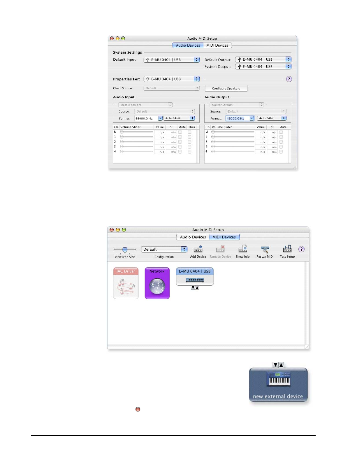
9. Click Go -> Utilities from the menu bar.
10. Double-click Audio MIDI Setup, then click the Audio Devices button if it’s
not already selected. The window shown on the following page appears.
11. Select the 0404 USB 2.0 for the following: Default Input, Default Output,
System Output, Properties For.
12. Play a song on iTunes to verify that the 0404 USB 2.0 is the default device for
audio playback.
13. Quit iTunes.
0404 USB 2.0 Owner’s Manual 9
Page 10
Software Installation
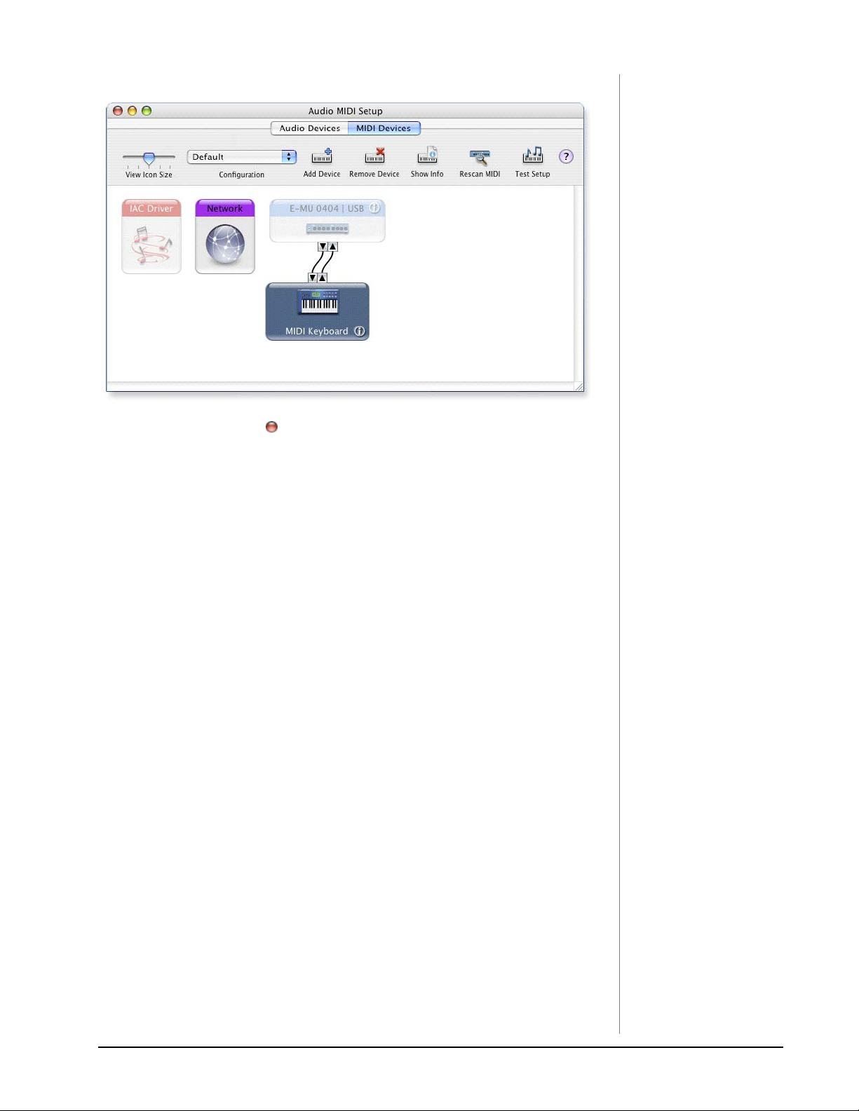
Setup the MIDI Devices
If you plan to use a MIDI keyboard, now would be a good time to set up your MIDI
devices. Connecting a MIDI keyboard will allow you to use the virtual instruments
provided in the software bundle and get the most out of your purchase.
14. Click the MIDI Devices button. The window shown below appears.
15. Click the Add Device button. A new external
device icon like the one shown at left appears.
16. Double-click on the new external device if you
want to set the MIDI Keyboard Properties. You
have the option to name and change the icon
for the device. Click Apply, then click the Close
button to close the Properties window.
17. Connect the new external device to the E-MU 0404 USB by dragging between
the input and output connectors.
10 E-MU Systems
Page 11
Software Installation
18. The window below shows a properly connected MIDI device.
19. Press the close button to close the Audio MIDI Setup window.
Install the Production Tools Software Bundle
20. Insert the Macintosh Production Tools CD into your CD-ROM drive.
21. Double-click on the installer package.
22. The installation splash screen appears. Follow the instructions on the screen.
23. Continue to install applications from the bundle as desired,
Uninstalling the Audio Drivers and Applications
At times you may need to uninstall or reinstall the 0404 USB 2.0 application and
device drivers to correct problems, change configurations, or upgrade outdated
drivers or applications. Before you begin, close the E-MU USB 2.0 Control Panel
application. Applications running during the uninstallation will not be removed.
1. Open the Applications folder.
2. Open the Creative Professional folder.
3. Open the E-MU USB Audio folder.
4. Click the E-MU USB Audio Uninstaller and follow the instructions.
0404 USB 2.0 Owner’s Manual 11
Page 12
Connection Diagrams
NOTE
The universal power
adapter comes with several
types of snap-on plugs.
Use the type of plug
appropriate for your
country.
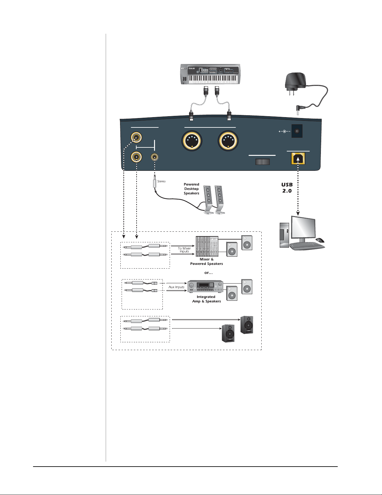
CONNECTION DIAGRAMS
MIDI Keyboard
MIDI
Out
MIDI
5VDC Adapter
In
WARNING!
Use only a USB 2.0 certified
Hi-Speed cable (like the
one supplied) for the USB
connection. Using a USB
1.1 cable may cause erratic
behavior and degraded
performance.
Outputs
L
R
1/4” TRS male to 1/4” TRS male
male RCA adapter
1 Main
(balanced)
1/4” TS male to
(unbalanced)
MIDI
In
Out
Power
Off On
5 VDC
USB 2.0
Computer
1/4” TRS male to 1/4” TRS male
(balanced)
(Note: TRS = Tip-Ring-Sleeve, TS = Tip-Sleeve)
Powered Speakers
12 E-MU Systems
Page 13

Connection Diagrams
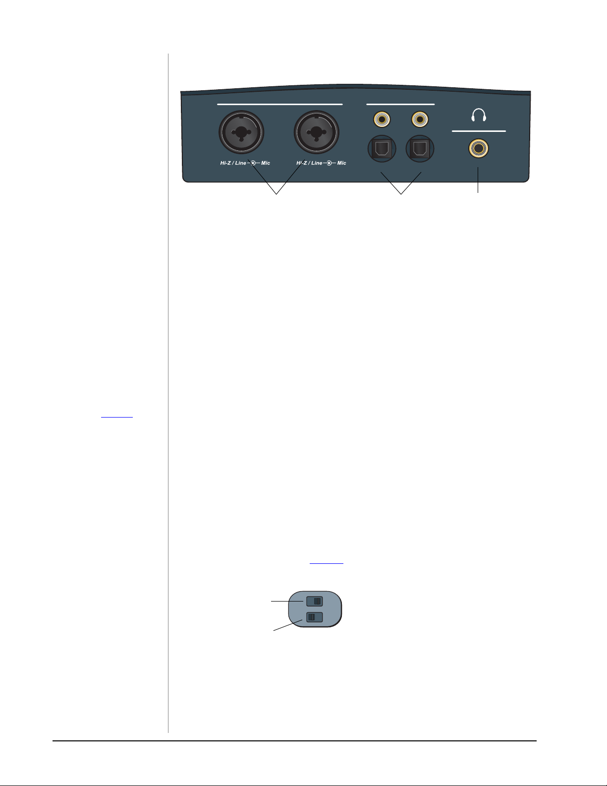
Analog Inputs/Outputs & S/PDIF
Stereo
Headphones
Instrument
Mic / Hi-Z / Line
A
B
CD Player
Any Dig ital Audio Devi ce with S/PDIF Out
Microphone
S/PDIF
Headphone
In
Out
Volume
Audio/Video Receiver
Any Dig ital Audio Devi ce with S/PDIF In
The Mic/Hi-Z/Line Inputs accept any balanced or unbalanced instrument, line level signal or
microphone. The coaxial/optical S/PDIF inputs and outputs allow you to interface with
external digital audio equipment.
0404 USB 2.0 Owner’s Manual 13
Page 14
Main Panel Controls
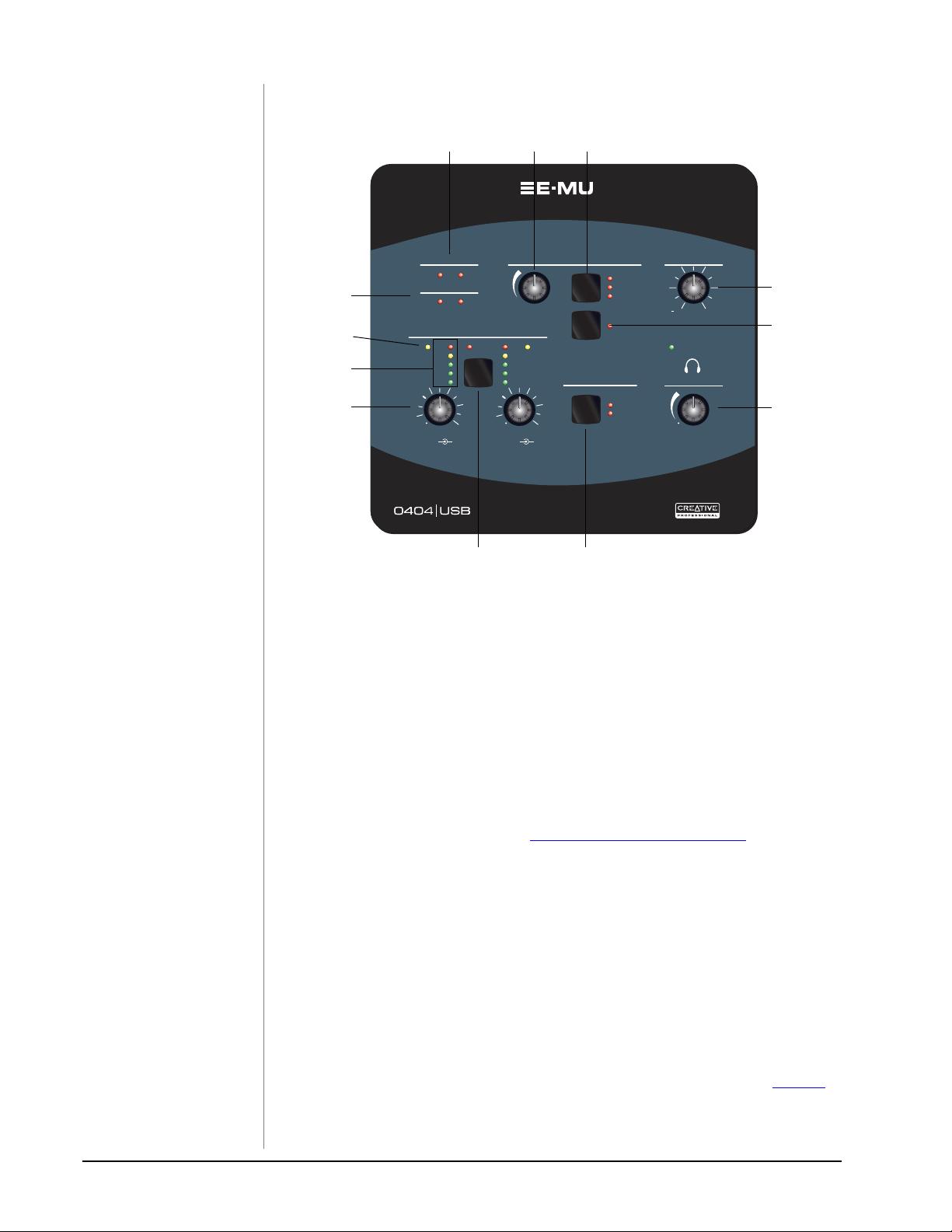
MAIN PANEL CONTROLS
1
MIDI
MIDI
InOut
Sync Status
6
7
8
9
Sync Status
Int
Ext
Mic / Hi-Z / Line
Mic / Hi-Z / Line
48V On
-3
-6
-12
-18
00
+65 +65
Hi-Z / Line
A
Mic
10
Hi-Z / Line
B
2 3
Level
SLSL
ClipClip
-3
-6
-12
-18
Mic
Direct Monitor
Direct Monitor
11
S/PDIF
Main
S/PDIF
Off
Mono On
Coaxial
Optical
Main Output
∞
Level
Power On
Headphone
Level
5
+0dB
4
12
1. MIDI In/Out Activity Indicators
These indicators light when data is being sent or received from the MIDI
ports.
2. Direct Monitor Level Control
This encoder controls the mix of the input signal into the output from full
level to off.
3. Direct Monitor Output Switch & Indicators
Turns direct monitoring on or off and allows you to send the direct monitor
signal to either the Main output or the S/PDIF output. The direct monitor
signal is a mix of all inputs. See “
Direct Monitoring” on page 21.
4. Mono Switch (Direct Monitor)
When on, the left and right direct monitor channels are summed to mono.
This feature is useful when the two inputs are being used for separate
instruments.
5. Main Output Level
Controls the Main Output level.
6. Sync Status Indicators
Indicates if the digital clock source is set to internal or external.
Select External Sync in the E-MU USB 2.0 Audio Control Panel to select
external clock. The External LED will flash if sync is not valid. See page 19
for additional information about using digital inputs.
14 E-MU Systems
Page 15
Main Panel Controls
7. Soft Limit LEDs
The Soft Limit LEDs indicate that the signal level is being soft limited. When
enabled in the E-MU USB 2.0 Audio Control Panel, the analog soft limiters
begin to gently turn down the gain whenever the signal level goes above -12
dBFS. The soft limiters allow you to run a hotter signal without fear of
clipping.
8. Signal Level & Clip Indicators
The LED signal level indicators show the signal level for both analog inputs.
The red clip indicators momentarily remain on whenever your input level
exceeds 0 dBFS. With a proper signal level, the yellow -3dB LED will come on
occasionally, but the red clip LED should never light.
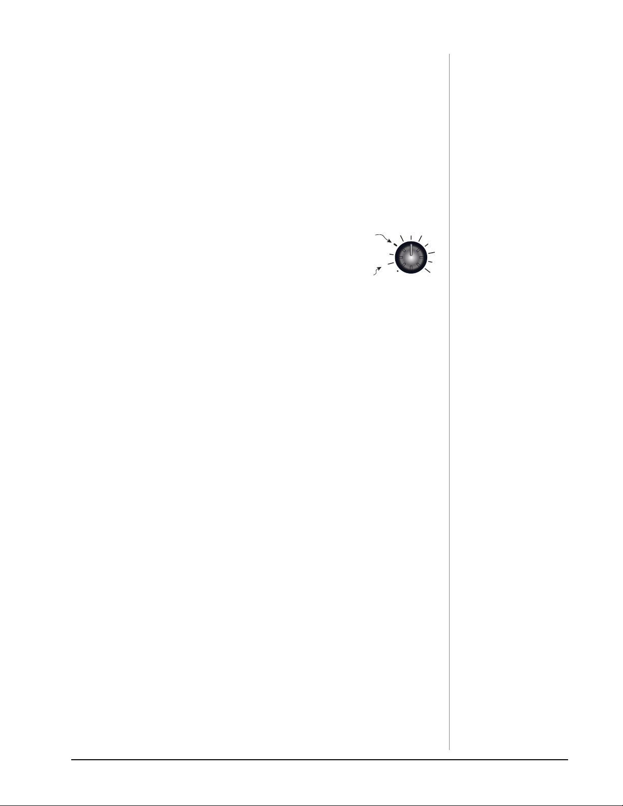
9. Input Level Gain Controls
The preamp level controls set the input gain from 0dB
to +65dB. The wide mark indicates the 0dB/unity
setting when using unbalanced input cables. The 0dB
mark indicates unity gain when using balanced input
cables.
0dB/Unity
(Unbalanced)
0dB/Unity
(Balanced)
0
+65
10. 48V On Switch & LED
This switch enables +48 Volts to both XLR inputs for powering microphones
that require phantom power. The red LED indicates that phantom power is
on.
11. S/PDIF Mode
Coaxial or Optical. This button selects between coaxial cable or optical inputs
for the S/PDIF digital interface. Both outputs are always active.
12. Headphone Level Control
This knob controls the volume of the Headphone output.
WARNING!
Some microphones cannot
tolerate phantom power
and may be damaged.
Check your microphone’s
specifications and requirements before using
phantom power.
0404 USB 2.0 Owner’s Manual 15
Page 16
Input/Output
INPUT/OUTPUT
NOTE
Unbalanced cables provide
6dB less level than
balanced cables. Adjust the
level using the input gain
control. See page 15
more information.
for
Mic / Hi-Z / Line
A
B
1
S/PDIF
Headphone
In
Out
23
1. Mic / Hi-Z / Line Inputs
These Neutrik combination jacks can be used either as balanced microphone
inputs, Hi-Z guitar pickup inputs or line level inputs.
XLR Connectors - Use for dynamic or condenser microphones.
(1=gnd, 2=hot, 3=cold)
1/4 inch Jacks - Center opening. Use for electric musical instruments
(i.e. guitar, bass, etc.), or line-level signals. The inputs are balanced, but you
can use either balanced (TRS = tip-ring sleeve) or unbalanced (TS= tip-sleeve)
cables for line-level signals (tip=hot, ring=cold, sleeve=gnd).
2. S/PDIF In/Out
Each jack carries two channels of digital audio data from external devices such
as external A/D-D/A converters or other digital devices with S/PDIF. Both the
coaxial (RCA) jacks and the optical ports carry identical data. Select the
output format you want to use in the E-MU USB 2.0 Control Panel (AES/EBU
or S/PDIF).
3. Headphone Output
The headphone output is designed to drive stereo headphones with 1/4”
stereo plugs. If your headphones have a smaller 1/8” plug, use a commonly
available plug adapter.
Ground Lift Switches
There are “ground lift” switches for both analog inputs located on the bottom
of the unit. These switches can be used to safely stop the hum if a ground loop
occurs in your setup. See page 48
No Input Ground
for more information.
A-GND LIFT
B-GND LIFT
Grounded Input
The input ground is lifted when the A or B slide switch is closest to the
GND LIFT label.
16 E-MU Systems
Page 17
Input/Output
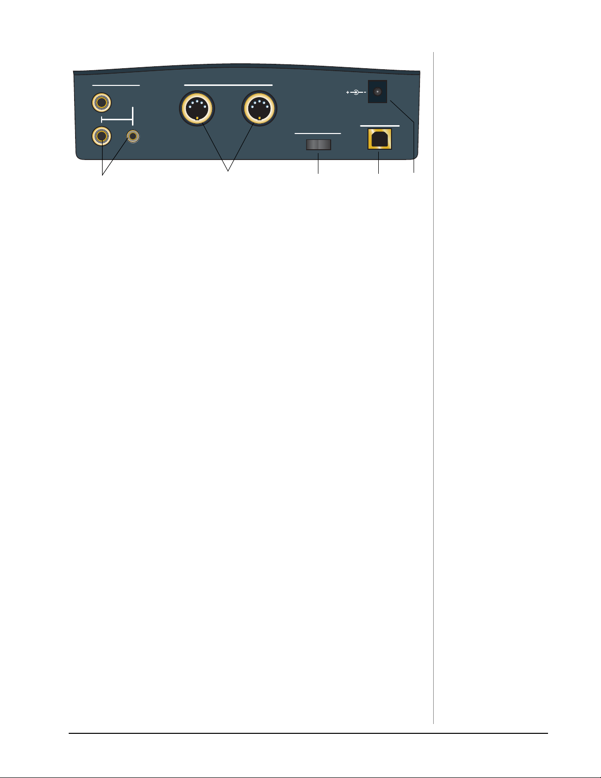
Outputs
L
R
1 Main
4
MIDI
In
Out
5
Power
Off On
6
5 VDC
USB 2.0
7
4. Main Outputs
The main outputs are normally connected to your monitoring system. The
signal is duplicated on a stereo 1/8¨ jack for easy connection to desktop
stereo speakers.
Use TS unbalanced cables for consumer-level line signals and TRS balanced
cables for pro-level line signals. Balanced cables provide +6dB more output.
5. MIDI In/Out
The MIDI input and output ports allow you to interface any type of MIDI
equipment such as keyboards, effect units, drum controllers (anything with
MIDI).
6. On/Off Switch
This switch turns the 0404 USB 2.0 on or off. Don’t cycle the power on and
off quickly or the internal computer may lock up. Wait a second or two
between power cycles.
8
7. USB
Connects the 0404 USB 2.0 to the USB 2.0 port on your computer via the
supplied USB cable and provides two-way, hi-speed communication. The
0404 USB 2.0 is NOT powered via USB and uses an external power adapter in
order to maintain the highest level of audio quality.
8. Power: 5 Volts DC
The 0404 USB 2.0 is powered from a +5VDC Adapter (supplied).
NOTE to PC Users:
When using a USB 1.1 port,
performance is limited to
16-bit and 44.1/48 kHz
recording and playback.
0404 USB 2.0 Owner’s Manual 17
Page 18

E-MU USB Audio Control Panel
E-MU USB AUDIO CONTROL PANEL
After you have successfully installed the audio drivers, launch the E-MU USB
Audio control panel. The E-MU USB Audio control panel is shown below.
• Windows:The E-MU USB Audio control icon will be visible in the Taskbar,
which is normally located in the bottom right of the screen. It can
also be launched from the Start Menu
(All Programs, Creative Professional, E-MU USB Audio Application).
• OS X The E-MU USB Audio control application is located in the Applications folder . You can also open the E-Control Application using
the icon on the desktop.
23
1
4
5
NOTE
There are some limitations
when operating at higher
sample rates.
PC at 174.4/192kHz
• No Direct Monitor
• Stereo I/O only
• MIDI Disabled
Mac
• 88.2/96k - Stereo I/O only
• 176.4/192k - Disabled
6
11
7
8
9 10
1. Skin
Choose between different appearances for the E-MU USB Audio control
panel.
2. View
Hide the application (Ctrl+H, Windows) You can restore the application by
clicking the E-MU icon in the System Tray (Windows), or by clicking the
E-MU icon in the Dock (OS X).
3. Help
About E-MU 0404 USB 2.0, Audio control, Launch Manual, Check Updates
4. Device
If you are using more than one E-MU USB Audio device, you can choose
which unit is currently being controlled.
5. Sample Rate
Allows you to set the system sample rate: 44.1kHz, 48kHz, 88.2kHz, 96kHz,
176.4kHz or 192kHz.
6. Sync Source
Selects internal or external sync.
18 E-MU Systems
Page 19

E-MU USB Audio Control Panel
7. Digital Input Status
Displays the sample rate of external sync source, if used.
8. S/PDIF Output Format
Selects between S/PDIF or AES/EBU format for the S/PDIF output. This sets
the S/PDIF-AES status bit, but doesn’t affect the signal level.
9. Soft Limit
Enables or disables the analog peak limiters on the inputs. Soft limiting
allows you to record a hotter signal without clipping. The soft limiters
gradually engage at -12 dBFS. Signal levels below -12 dBFS are unaffected.
10. Tool Tips
Enables or disables pop-up tool tips about E-MU USB Audio control
functions.
11. Lock Indicator
Indicates that the 0404 USB 2.0 is locked to an external clock source.
S/PDIF
S/PDIF (which stands for Sony/Philips Digital Interface Format) carries two
channels of digital audio at sample rates of up to 96kHz, and also carries an
embedded clock for synchronization. The 0404 USB 2.0 provides two types of
S/PDIF: Coaxial or Optical.
The Coaxial interface has an advantage of using commonly available RCA-type
connectors. However, high-quality cable should be used to avoid data dropouts
and interference from radio frequency radiation. Coaxial S/PDIF uses a transformer on the transmitting end to prevent ground loops, but ground loops may
still occur, mainly because of improper S/PDIF implementation on some
equipment.
TIP . . .
The following functions are
stored in non-volatile
memory if the unit is left
powered on for 5 seconds
after the setting is changed.
• Phantom Power on/off
• Soft Limit on/off
• S/PDIF Output Routing
• Sync Source
NOTE
The S/PDIF digital input is
not available at 176.4 or
192 kHz.
The Optical interface is immune to radio interference and also prevents ground
loops between different pieces of equipment. On the downside, optical fiber is
generally more expensive than coaxial cable. For best performance use high-quality
glass cables. Plastic fiber lightpipes work well for short distances.
Using External Synchronization to S/PDIF
To synchronize to an “External” S/PDIF sync source, you must use the 0404 USB
Control Panel to set the sample rate to match the external device, then switch to
external sync. In addition, the S/PDIF source must be chosen by pressing the
S/PDIF button to specify Coaxial or Optical input.
Refer to the information on the following page for additional information about
S/PDIF synchronization.
S/PDIF to Analog / Analog to S/PDIF converter
The 0404 USB can be also used as a standalone S/PDIF -> Analog or Analog ->
S/PDIF converter.
Analog Input to S/PDIF: Attach analog device to Dock A/B (Left/Right); enable
direct monitoring (set to S/PDIF). Analog input will be mirrored to S/PDIF out.
S/PDIF to Analog: Attach a S/PDIF source, power cycle the device, and set direct
monitor to “Main”.
TIP . . .
The 0404 automatically sets
its sample rate and locks to
the source if a S/PDIF
source is present at powerup.
If you are having a difficult
time setting up S/PDIF sync,
connect the source, then
power cycle the 0404 USB.
It should automatically sync.
0404 USB 2.0 Owner’s Manual 19
Page 20

E-MU USB Audio Control Panel
Synchronizing the 0404 with other Digital Devices
When interconnecting two digital audio devices using a digital interface such as
S/PDIF, the two devices must be properly synchronized. Unsynchronized digital
audio will result in random clicks, pops and dropouts, or even no audio at all.
Two digital devices are properly synchronized when one unit is supplying the
master clock to the other unit (the slave) and the slave is set to receive external
clock. Make sure you set the sync source to External and set the sample rate to
match the external device in the E-MU 0404 USB Control Panel. The diagrams
below show two ways to synchronize an external device.
NOTE to PC Users:
S/PDIF is only available for
recording via ASIO and
Kernal Streaming, you
cannot record S/PDIF with
MME applications.
• The digital audio input is UNSYNCED if BOTH Sync Status LEDS are on.
• The internal and external sample rates are mismatched if the “Ext” LED is
flashing.
0404 USB 2.0
Slave
S/PDIF
(Optical)
In Out
External Device supplies Master Clock
(via S/PDIF)
The S/PDIF cable carries two
channels of audio data and
an embedded clock.
or
In Out
S/PDIF
(Coax)
Set 0404 USB 2.0 to receive:
External Sync
0404 USB 2.0
Master
S/PDIF
(Optical)
In Out
In Out
S/PDIF
(Coax)
Master
This S/PDIF cable carries two
channels of audio data.
Slave
This S/PDIF cable carries an embedded
clock signal from 0404 USB 2.0.
S/PDIF Out
External A-D Converter
(or other digital audio device)
0404 USB 2.0 supplies Master Clock
(via S/PDIF)
Set this device to receive:
External S/PDIF Sync
S/PDIF In
S/PDIF Out
External A-D Converter
(or other digital audio device)
The Sync Status indicators on the 0404 USB 2.0 function as follows:
INT solid ................................Internally sync’d, no external digital input detected.
INT solid + EXT blinking ....Internally sync’d, external digital input of different
sample rate detected; MUTE S/PDIF input
INT solid + EXT solid ...........Internally sync’d, external digital input of same
sample rate detected.
EXT solid ...............................Externally sync’d; valid S/PDIF input present
20 E-MU Systems
Page 21
Direct Monitoring
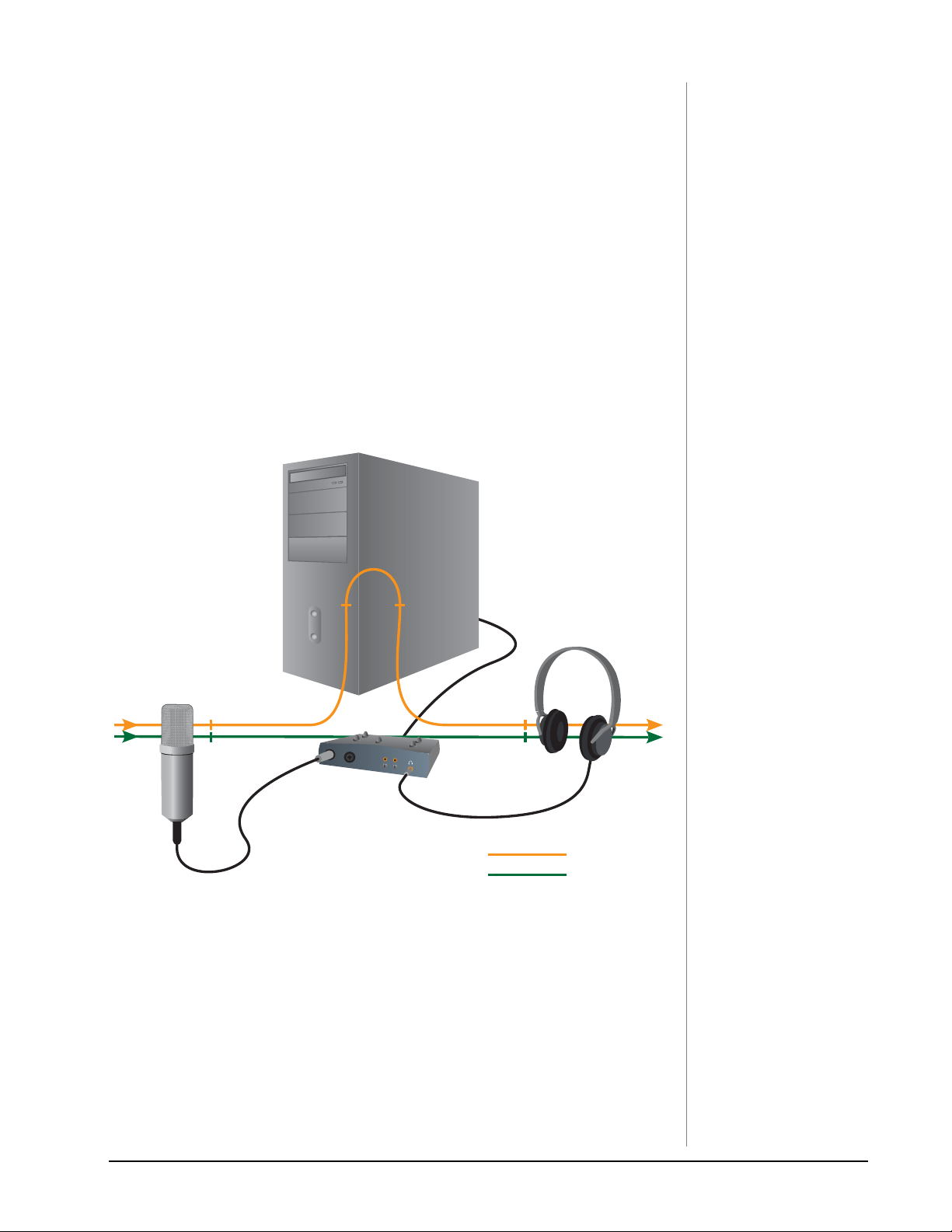
DIRECT MONITORING
Direct monitoring allows you to monitor inputs without having any software
open. It can also be used as an alternative to software monitoring if you desire the
lowest latency monitoring possible.
When using a computer for digital recording, an audible time delay occurs while
the audio signal is being input to the computer, processed by the software and then
returned to the output for monitoring. This time delay is called Latency.
Latency becomes a problem when you have to use high buffer settings to conserve
CPU resources. Because the 0404 USB 2.0 has hardware direct monitoring, you can
enjoy zero latency regardless of your buffer setting.
The Direct Monitor feature connects the input signals to the selected outputs when
recording so that you can hear your performance without delay. The Direct
Monitor level control lets you adjust the volume of the input signal in relation to
the recorded tracks.
Direct monitoring is controlled manually from the Direct Monitor switch on the
0404 USB 2.0. It’s not necessary to turn it on in your recording application.
Latency (delay)
NOTE to PC Users:
Direct monitoring is not
available at 176.4 or
192 kHz.
Software Monitoring
Direct Monitoring
Direct Monitoring allows you to listen to the direct sound of your instrument during
recording, without the delay incurred by going to the computer and back.
Direct Monitoring vs. Software Monitoring
Direct monitoring is lower latency and can also be used without software running
(or even without a computer!).
Software monitoring has the advantage of allowing audio effects or EQ added in
the host software to be heard on the output. Its round-trip latency depends on
what latency is chosen. If you choose to software monitor, make sure to disable
direct monitoring. If both are enabled, you will experience a ‘comb filter’ or
doubling effect.
0404 USB 2.0 Owner’s Manual 21
Page 22

Tutorials
WARNING!
Windows Users - After
checking your audio, be
sure to quit Windows Media
Player.
TUTO RI ALS
Introduction
This guide contains step-by-step walk-throughs of basic recording operations using
your E-MU 0404 USB 2.0 interface with software applications for your Windows or
Macintosh computer. We encourage you to perform the steps on your computer as
you read so that you become familiar with the process. The first tutorial only takes
about half an hour to complete, by which time you’ll know how to make a multitrack recording.
NEED MORE HELP?
If you need additional help with the bundled applications, please see
• Windows: Program Files\Creative Professional\E-MU 0404
USB\Documents\ 3rdParty.htm.
• OS X: Applications Drive\Library\Documentation\E-MU 0404 USB
Before you Begin...
• You should have already installed the E-MU software on your computer
• You should hear the computer sounds coming out of the E-MU 0404 USB 2.0
and your speakers when you play a CD or an MP3 using Windows Media
Player or iTunes. If not, make sure your E-MU 0404 USB 2.0 is properly
connected according to the diagram on page 12
• A source of audio should be connected to the inputs (a microphone, musical
instrument, or CD/MP3 player).
.
TIP . . .
If you have two or more
hard disks, it’s better to
store audio files on a disk
that isn’t running your
OS.
Getting Started with Steinberg Cubase LE (Windows)
Steinberg Cubase LE is a 24-bit, multi-track audio/MIDI sequencer with highquality effects, automation, virtual instruments (VSTi), and many other professional features.
The following step-by-step tutorials are designed to get you recording as quickly as
possible. After you have finished the tutorial we encourage you to read the Cubase
LE PDF manual in order to learn about the many features of this powerful
program.
1 - Setting up Cubase LE
Follow these instructions carefully to ensure that Cubase LE runs smoothly the first
time. Cubase LE will remember these settings, so you’ll only have to do this once.
1. Open Cubase LE from the Start menu. An ASIO multimedia driver test dialog
box will pop up to ask if you want to run the ASIO test. Choose No, because
you won’t be using the driver anyway.
2. Select New Project from the File menu.
3. Select Empty and click OK.
4. A Select Directory pop-up dialog box
will appear. Choose a location on your
hard disk where you want to store your
audio files, then click OK.
5. The Cubase LE Project window appears.
22 E-MU Systems
Page 23

Tutorials
6. Select Device Setup… from the Devices menu.
7. Select VST Multitrack from the Devices list.
8. In the Setup section of the dialog box, select ASIO E-MU 0404|USB. A pop up
dialog box asks, if you want to keep or switch the ASIO driver. Select Switch.
Buffer Latency Setting
9. Click the Control Panel button. The popup dialog box shown at right appears.
10. Set the ASIO Buffer Latency as low as
your computer will allow and click OK.
(10ms is a good starting point.)
A low latency setting is important to
assure fast response when using virtual
instruments and to minimize delay when
monitoring through Cubase. If you hear crackles or other audio problems, try
increasing the Buffer Size.
11. Close the Device Setup screen by clicking OK.
12. Note: If the Cubase LE application crashes for any reason, it is recommended
that you re-boot the computer.
13. Select Project Setup from the Project menu. This is where you set the Sample
Rate and Record Format (bit depth), among other things. Set the Record
Format to 24-bits and the Sample Rate to 44.1kHz.
0404 USB 2.0 Owner’s Manual 23
Page 24

Tutorials
14. Select VST Inputs from the Devices menu. This is where you enable the inputs
you wish to use. Make the inputs active.
2 - Basic Multitrack Recording
This tutorial assumes you’re using a single input or a pair of inputs. For more
advanced recording, refer to the Cubase LE manual.
Add an Audio Track
1. From the Cubase LE menu bar, select Project, Add Track, Audio. An audio
track is added to the project window.
NOTE
If the Inputs aren’t available,
check Devices, VST Inputs.
Inspector button
Track InputMonitor
Stereo/Mono button
2. The screen shows the “A” input of the 0404 USB. Note that IN 1 is shown in
the Track Input field (Input A =IN1, Input B =IN2). If you want to record in
stereo, turn the Stereo/Mono button On and select IN 1 + IN 2 for the Track
Input.
3. Make sure the Monitor button is OFF. You will be monitoring the input
through the E-MU 0404 USB 2.0.
24 E-MU Systems
Page 25

Tutorials
4. Press the Direct Monitor button on your E-MU 0404 USB 2.0. The LED
should show Main. If you are recording a mono track, set Direct Monitor to
Mono by pressing the Mono On button.
Get Ready To Record
5. Plug in your instrument or microphone and set the input gain control for a
good signal level. The meters should show signal activity, but the clip LED
should never come on.
6. You should be hearing your instrument or microphone through your monitor
speakers or headphones. If not, go back to steps 4 and 5.
7. Optional Step - Metronome: To toggle the Metronome on and off, press C on
the computer keyboard. To adjust the metronome output level, press the
transport Play control, then select Metronome Setup... from the Transport
menu. Use the volume slider to set the desired metronome level.
8. Press the Go to Start button .
9. Make sure the Record Enable button on the track is on (it should be by
default).
Record Enable
10. Press the Record button on the Cubase transport control panel. The button
turns red and you’re recording.
Direct Monitor
Main
S/PDIF
Off
NOTE
Turning on the metronome
adds a 2-bar lead-in before
recording begins.
Record
PlayStopGo to Start
11. When you’re finished recording your track, press the Spacebar, or press the
Stop button on the Cubase Transport Control.
12. Press the Go to Start button .
13. Press the Spacebar or press the Play button to play back your new Track.
Record Another Track
14. Press the Go to Start button .
15. Drag the audio chunk you just recorded down below itself and release the
mouse button. A new track is automatically created with your recording. This
is by far the quickest and easiest way to set up a new track in Cubase. Now
you’re all set to record again on Track 1.
Drag
16. Press the Record button on the Cubase transport control panel and you’re
recording again. You’ll hear your first track playing along with you.
17. Repeat steps 12-14 to record more audio tracks.
18. Press the Mute button to silence any tracks you don’t want to hear.
0404 USB 2.0 Owner’s Manual 25
Page 26

Tutorials
3 - Recording a MIDI Track using Proteus VX
You’ll need a MIDI keyboard (or other MIDI input device) for this tutorial.
Make the Connections
1. Connect the MIDI out of your MIDI keyboard to the MIDI input of the 0404
USB 2.0.
2. From the Project menu, select Add Track, MIDI.
The Cubase Project Window should now look more or less like the one below
with one or more Audio tracks and one MIDI track:
MIDI Track
3. Click the Devices menu, and select VST Instruments.
26 E-MU Systems
Page 27

Tutorials
4. From the VST Instruments window, select E-MU, then ProteusVX .
The VST Instruments window now looks like this.
Edit Button
5. Take a look at the Inspector area on the left side of the Cubase LE project
window. Make sure the input to the MIDI track is connected to the E-MU 0404
USB 2.0.
6. The Output is not yet connected to anything. Click on the Output and select
ProteusVX.
Input
7. Click the Edit button of the VST Instruments window to open Proteus VX.
Alternatively, you could click on the Edit button of the track Inspector to open
Proteus VX.
8. Next, you have to load the Proteus X Composer bank. Select Open from the
File menu. and locate the Proteus X Composer sound bank. The banks is
installed here: “Program Files/Creative Professional\ E-MU Sound
Central\Proteus X Composer.” Loading takes a few seconds.
9. Bring up the mini keyboard by clicking the icon on Proteus VX and play a
few notes. You should be hearing sound. If not, verify that the 0404 USB 2.0 is
properly configured.
10. Play your MIDI controller and verify that it plays Proteus VX.
11. Change the Preset using the inc/dec keys of the prg: field of the inspector.
The preset on Proteus VX should change to follow the one
in Cubase LE. If not, make sure the Receive Program Changes box is checked
in Proteus VX (Options, Preferences..., MIDI).
12. Feel free to play around for awhile and don’t worry about losing anything.
Nothing is made permanent until you Save the bank, so have fun.
0404 USB 2.0 Owner’s Manual 27
Page 28

Tutorials
To Record a MIDI Track
13. Make sure the Record Enable button on the MIDI track is on (it should be by
default).
Record Enable
14. Click Record on the Cubase LE Transport control and start playing your MIDI
controller.
Record
15. Press Stop when you’re finished recording the first track.
16. Press the Go To Start button .
17. Press Play on the Cubase Transport to play back your track.
To Record a M I D I Tr ack on another MIDI Channel
Proteus VX VSTi can play back up to 16 MIDI tracks at once. It’s much more efficient to
use several channels on one VSTi than to use multiple VSTi’s with one channel each.
18. From the Project menu, select Add Track,
MIDI. Notice that the channel number in
the Inspector section is now set to chn:2.
Channel
19. Select Proteus VX as the Output destination in the Inspector section.
20. Select a new Preset for this track using the
inc/dec keys of the prg: field of the inspector.
21. When you’re ready, click Record on the Cubase LE Transport and start playing.
22. Click Stop when you’re finished recording, press the Go to Start button on
the transport, then Play. Proteus VX now plays both MIDI channels.
On Your Own
Cubase LE and Proteus VX include excellent online documentation and help files.
Take the time to learn all the features of these powerful programs, and most of all
have fun.
28 E-MU Systems
Page 29

Tutorials
Getting Started with Cakewalk Sonar LE (Windows)
Sonar LE is a 24-bit multi-track audio/MIDI sequencer with high-quality effects,
automation, virtual instruments (VSTi/DXi), and many other professional features.
IMPORTANT: During installation of Sonar LE you will be asked to run the
Cakewalk VST Adapter. You must do this in order for Sonar to recognize Proteus
VX or any other VST plug-ins.
The following step-by-step tutorials are designed to get you recording on Sonar LE.
After you finish the tutorial we encourage you to read the Sonar LE PDF manual in
order to learn about the many features of this comprehensive program.
1 - Setting up Sonar LE
Follow these instructions carefully to ensure that Sonar LE runs smoothly the first
time. Sonar LE will remember these settings, so you’ll only have to do this once.
Run Sonar LE for the first time
1. Open Sonar LE from the Start menu or by double-clicking on the desktop
shortcut. The first time you run Sonar LE, the following dialog box appears:
2. Click No to close the dialog box. (The tests do not apply to the 0404 USB 2.0.)
Sonar LE opens and the following dialog box appears.
3. Click Close to close the dialog box. The Sonar Project Window appears.
0404 USB 2.0 Owner’s Manual 29
Page 30

Tutorials
Setup the Audio Options
4. From the Options menu, select Audio. The following dialog box appears.
5. Click on the Advanced Tab to access the next window.
6. Select ASIO as the Driver Mode and click OK. You’ll get a pop-up dialog box
explaining that the ASIO settings won’t take effect until the next time you start
Sonar LE.
7. Close Sonar LE completely and restart the application.
30 E-MU Systems
Page 31
Tutorials
Return to the Audio Setup Options
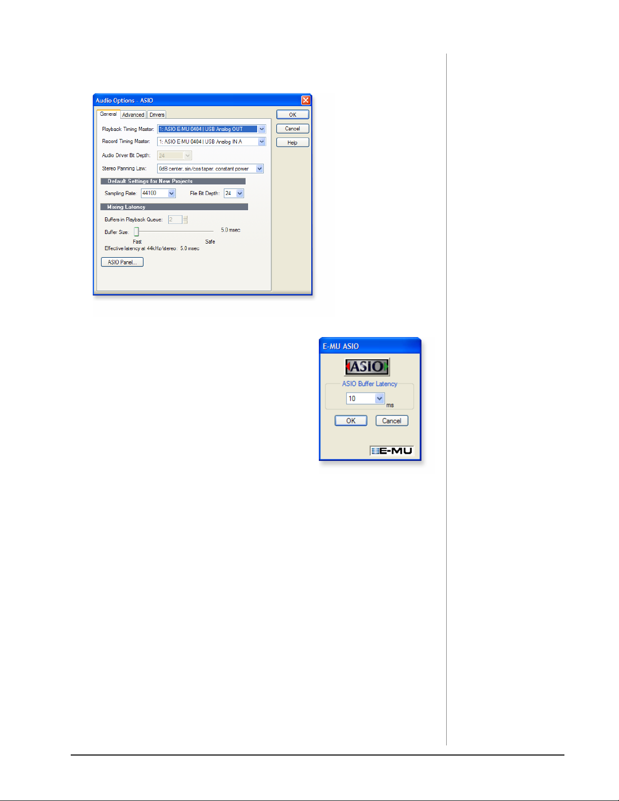
8. Once Sonar LE has restarted, select Audio from the Options menu.
9. Click the ASIO Panel. The pop-up dialog box
shown at right appears.
10. Set the ASIO Buffer Latency as low as your
computer will allow. A low latency setting is
important to assure fast response when using
virtual instruments and to minimize delay when
monitoring through Sonar LE. If you hear
crackles or other audio problems, try increasing
the Buffer Size.
11. Close the Audio Options screen by clicking OK.
Note: If the Sonar LE application crashes for any
reason, it is recommended that you re-boot the
computer.
Set the Location of your Audio Files
12. From the Options menu, select Global.
13. Select Audio Data, then select a location for the Global Audio Folder.
TIP . . .
If you have two or more
hard disks, it’s better to store
audio files on a disk that
isn’t running your OS.
0404 USB 2.0 Owner’s Manual 31
Page 32

Tutorials
2 - Basic Multitrack Recording
This tutorial assumes you’re using a single input or pair of inputs. For more
advanced recording, refer to the Sonar LE manual. Sonar opens by default with
with 2 audio tracks and 2 MIDI tracks.
The Sonar Project Window
Inspector Restore Strip Size
Track Record Enable
Step 3
1. Click the Restore Strip Size
button for Track 1. This reveals
the input and output routing of
the track. The E-MU 0404 USB
2.0 will already be selected as the
Input
Output
Click
Here
output destination.
2. Select the input source by clicking on the small triangle on the input field. If
you wish to record a mono signal on the “A” input of the 0404 USB, select Left
ASIO E-MU 0404 USB Analog In A. To record both inputs in stereo select
Stereo ASIO E-MU 0404 USB Analog In A.
3. The Input Echo button should be OFF. You will be monitoring the input
through the E-MU 0404 USB 2.0.
4. Press the Direct Monitor button on your E-MU 0404 USB 2.0. The LED
should show Main. If you are recording a mono track, set Direct Monitor to
Mono by pressing the Mono On button.
TIP . . .
If you don’t see meter
activity on the track, check
the Input for the track.
Make sure you are selecting
the proper input source.
5. Press the Track Record Enable button for the track. (See the diagram
above.) The track turns a dull red color to indicate that it is record-enabled.
You should now see activity on the Track Input Meter when feeding a signal
into the 0404 USB 2.0.
6. If your input signal is either too weak or too strong, adjust the input level
control on the 0404 USB 2.0.
32 E-MU Systems
Page 33

Tutorials
7. Optional Step - Metronome: First, select Toolbars from the View menu and
check the Metronome Toolbar. Next turn Metronome During Record On by
clicking the button.
Record a Track
8. Press Record on the Sonar LE Transport control and start playing.
Stop
Return-To-Zero
Record
Play
9. Press Stop when you’re finished recording the first track.
10. Press Play on the Sonar LE Transport to play back your track.
11. If you want to dump the track and start over, Right-click over the waveform
display in the track and choose Delete.
Record Another Track
12. Select Track 2 and click the Restore Strip Size button to expose the input
and output routing.
13. Set the Input source for the track. Click on the little triangle on the right
side of the track Input box.
14. Disable record for Track 1 by clicking on the Track Record button Off.
15. Enable recording for Track 2 by clicking on the Track Record button On.
16. Press the transport Record button and you’re recording.
TIP . . .
You can create a new track
by selecting Clone, from the
Track menu. This handy
feature duplicates the
currently selected track
complete with input/output
routings.
Hot Tip: A quick way to record additional tracks using the same input is to simply
drag the Part (audio region) you just recorded up or down to another track in the
Sonar Project Window, then just hit Record again and go. (Choose Blend Old and
New when asked in the Drag & Drop Options.)
Save your Project
17. Choose Save As… from the Sonar LE File menu to save your project. Choose a
name and location that will make the project easy to find later.
0404 USB 2.0 Owner’s Manual 33
Page 34

Tutorials
3 - Recording a MIDI Track using Proteus VX
These instructions explain how to start Proteus VX from within Sonar LE. You’ll
need a MIDI keyboard (or other MIDI input device) for this tutorial.
• Important: If Sonar was installed BEFORE Proteus VX VSTi, you will have to
run the Cakewalk VST Adapter before Sonar can use the VSTi. (Start,
Programs, Cakewalk, Cakewalk VST Adapter).
1. Connect the MIDI output of your MIDI keyboard to the MIDI input of the
0404 USB 2.0.
Select the Virtual Instrument
2. Select Synth Rack from the View menu. The following window appears:
Click Here
3. Click on the
+ symbol to add an instrument. Follow the path shown above
and select Proteus VX from the list of VST instruments. The following pop-up
dialog box appears.
4. Select the default options (MIDI Source Track & First Synth Output) as shown.
Click OK to continue. (This may a take a few seconds.)
5. Proteus VX now appears in the Synth rack and two new tracks have been
added to the bottom of the track list. (You may have to scroll down to see the
new tracks.)
New Proteus VX Tracks
Audio Output from Proteus VX
MIDI input to Proteus VX
Click Here to view the strip controls.
34 E-MU Systems
Page 35
Tutorials
The MIDI Connection
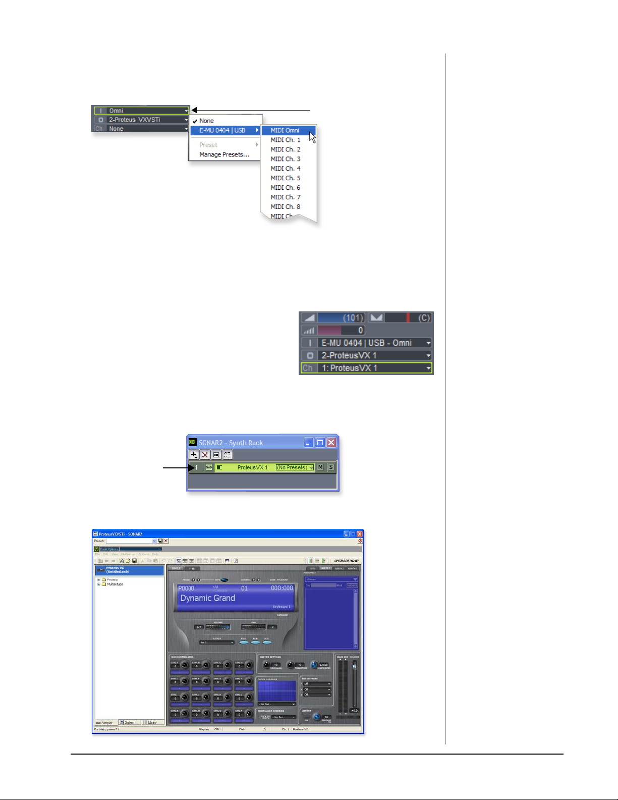
6. Select the blue MIDI Input track by clicking on it. The MIDI Input connection
appears in the strip to the left of the MIDI tracks.
MIDI Input Select
7. The E-MU 0404 USB 2.0 should already be selected as the MIDI input in
Omni mode as shown above. “MIDI Omni” allows Proteus VX VSTi to receive
on all 16 MIDI channels from your MIDI keyboard. (Proteus VX VSTi is
“multi-timbral” and can assign a different preset to each of the 16 MIDI
channels.)
8. Set the MIDI Channel for the track to
channel 1 as shown at right. This “rechannelizes” the incoming MIDI data on any
MIDI channel to channel 1.
Open Proteus VX
9. Double-click on the number (or on the Proteus VX name) to open the Proteus
VX editor.
Synth Rack with Proteus VX
Double-Click Here
to Open Proteus VX
10. After a few seconds, the Proteus VX application window shown below appears.
TIP . . .
Check the Sonar MIDI
Monitor in the SysTray to
verify that you’re receiving
MIDI.
0404 USB 2.0 Owner’s Manual 35
Page 36

Tutorials
Play the Proteus X Composer Bank.
11. Select the 16 channel tab. This page allows you to select presets for all 16 MIDI
channels.
16 Channel Tab
Select Preset
12. Select a preset for MIDI Channel 1 by clicking the little triangle.
13. Play your MIDI keyboard and verify that it plays Proteus VX.
14. Feel free to play around for awhile selecting presets and exploring Proteus VX.
Don’t worry about losing anything. Nothing is made permanent until you
Save the bank, so have fun.
To Record a M I D I Tr ack
15. Minimize the Proteus VX window by pressing the minimize button .
16. Record-Enable the MIDI Track by pressing the track Record button (R). The
track turns a dull red color to indicate that it is record-enabled.
• Important: Be sure to turn Track Record Enable OFF for any tracks you don’t
want to record on, such as previously recorded tracks.
Track R e c o rd Ena b l e
17. Press Record on the Sonar LE Transport control and start playing.
18. Press Stop when you’re finished recording the first track.
19. Press Play on the Sonar LE Transport to play back your track.
To Record a M I D I Tr ack on another MIDI Channel
Proteus VX VSTi can play back up to 16 MIDI tracks at once. It’s much better to use
several channels on one VSTi than to use multiple VSTi’s with one channel each.
20. Select MIDI Track from the Insert menu.
36 E-MU Systems
Page 37

Tutorials
21. Select the MIDI input for the new MIDI track. Select MIDI Omni as you did
before.
22. Select Proteus VX as the Output destination for the track.
23. Select MIDI Channel 2 in the Ch. field as shown below.
Input Select
Output Select
MIDI Ch. Select
Chan. 2
Selected
24. Restore Proteus VX by clicking on the Restore Up button on the minimized
Proteus FX window. Select a preset for channel 2 by clicking the little triangle
on channel 2 in the 1-16 channel view of Proteus VX.
25. Play your MIDI keyboard to listen to the presets during the selection process.
Click OK when you’ve made your selection.
26. Record Enable the track by pressing the Track Record Enable button . If
you want to record multiple tracks simultaneously, simply turn Record Enable
on for each track you wish to record.
27. Press Record on the Sonar LE Transport control and start playing.
28. Press Stop when you’re finished recording the second track.
On Your Own
Now that you’ve had a taste of Proteus VX, please read the Proteus VX Operation
Manual PDF to learn all about this exceptional instrument. Sonar LE also includes
useful online documentation and help files to help you learn about the features of
this powerful program.
0404 USB 2.0 Owner’s Manual 37
Page 38

Tutorials
NOTE
The first time you run Live,
you may get the message,
”Audio is disabled. Please
choose an audio output
device from the Audio
Preferences.” Simply follow
the instructions in “1-Setting
up the Preferences” to
correct the situation.
Getting Started with Ableton Live Lite 4 (Windows/OS X)
This guide contains a basic walk-through of Ableton Live Lite 4 (E-MU Edition) to
get you recording and playing back audio. A Proteus VX tutorial is also included for
Windows users. We encourage you to perform the steps on your computer as you
read so that you can “learn by doing.”
Ableton Live Lite 4 is an innovative composition and performance tool. Live
combines digital recording, virtual instruments, and digital effects with an original
interface design that many people find more intuitive than traditional designs.
The following step by step tutorials are designed to get you recording as quickly as
possible. After you’ve finished the tutorial we encourage you to follow Ableton
Live’s excellent interactive Lessons and read the Ableton Live reference manual pdf
in order to learn more about the program.
Before you Begin:
• You should have already installed the 0404 USB 2.0 and software on your
computer according to the instructions in your printed “Getting Started”
manual.
• You should have already installed the Ableton Live Lite 4 software on your
computer according to the instructions provided with the Ableton software.
• You should hear sounds from Ableton Live Lite 4 when you play the Ableton
demo.
• You should have your MIDI keyboard connected if you want to record MIDI.
1 - Setting up the Preferences
Unlock Ableton Live Lite 4 for E-MU by following the instructions in the Preferences menu. (Windows - Options menu, Preferences; OS X - Live menu, Preferences)
Read the following instructions to configure the Audio and MIDI preferences. Live
will remember these settings, so you’ll only have to do this once.
Set up the Plug-ins
The following steps allow Ableton Live Lite 4 to find the VST Plug-ins and Proteus
VX.
1. Click on the Plug-ins tab of the Preferences dialog box under the Options
menu (Windows) or Live menu (OS X). The following screen appears.
WindowsOS X
Steinberg\VSTplugins
Turn O n :
Then Re-Scan Plug-ins
Use Audio Units &
Use VST Plug-in System Folders
Locate:
38 E-MU Systems
Page 39

Tutorials
OS X Users
2. Turn on Use Audio Units.
3. Turn on Use VST Plug-in System Folders.
4. Press the Re-scan Plug-ins button. (You may have to wait a few seconds.)
Windows Users
5. Press the Browse button, then locate VST Plug-ins located in the Steinberg
folder. (Default path: C:\Program Files\Steinberg\VstPlugIns\)
6. After selecting the VST plug-ins folder, press OK. (You may have to wait a few
seconds while Ableton locates the plug-ins.)
Set up the Audio Parameters
7. Click the Audio tab of the Preferences dialog box. The Audio Setup page
appears.
WindowsOS X
Set up the Audio Parameters as shown above.
8. Windows Users: Select ASIO and ASIO E-MU 0404|USB as the Audio Device.
OS X Users: Select Core Audio and E-MU 0404|USB as the Audio Device.
NOTE
Windows Users: If the plugins do not appear after
selecting the proper folder,
press the Re-scan button.
Set up the MIDI Parameters
9. Click the MIDI/Sync tab of the Preferences dialog box. The MIDI Setup page
appears.
Close
Close
WindowsOS X
Select
MIDI
Interface
NOTE
Live enables every MIDI
input by default
10. The 0404|USB should appear in the list. Make sure it’s selected.
11. Preference Setup is now complete. Click the close button to close the window.
0404 USB 2.0 Owner’s Manual 39
Page 40

Tutorials
Click Here
File Browser 1
Open Folder
Starter Sets
Open Folder
breaks Sounds
Drag & Drop
Drum Clips
2 - Playing Audio Clips
Ableton Live Lite contains a bunch of great pre-recorded audio clips. In this short
section, you’ll learn to select and play clips.
1. Select New Live Set from the File menu. A new Ableton Live set opens with
two audio tracks and two MIDI tracks such as the one shown below. If the
window doesn’t look like the one below, click the Session View button.
Session View Button
Note...
On the Macintosh,
the folder “Starter
Sets” is located
inside the “Demos
and Tutorials” folder.
Show/Hide In/Out Section
2. Follow the three steps shown above in the diagram to open the “breaks
Sounds” folder. Note: On the Macintosh, the folder “Starter Sets” is located
inside the “Demos and Tutorials” folder.
3. Drag and drop the drums01-1.wav and drums01.wav clips over to Audio
Track 1.
4. Now click on the Clip Launch Button (little triangle) on one of the
clips you just dragged over. The loop begins playing. To stop playing, press the
Stop button on the transport.
5. Click the Clip Launch Button on the other clip. The new clips begins as soon
as the first one is finished.
6. Try out more pre-recorded audio clips. (To delete a clip, just select it and press
Delete.)
7. Press the Stop button in the Transport to stop playing.
8. When you’re finished exploring, and are ready to go on to the next tutorial,
just make sure that you have at least one drum clip in Audio Track 1 and one
empty slot in Audio Track 2.
40 E-MU Systems
Page 41

Tutorials
3 - Recording Audio into Ableton Live
1. Select an empty Audio Track with no clips.
2. From the View Menu on Ableton Live, select In/Out.
(Alternatively, you could also click the “Show/Hide In/Out Section
button” as shown in the diagram on the previous page.) Several
more options now appear in the mixer strips.
3. Input channels 1/2 are selected by default (stereo). If you
want to record a mono track select input 1 or 2 from the
drop-down menu.
4. Feed an input signal into the 0404 USB 2.0 from a guitar, keyboard, CD player
or other audio source. A mini-meter appears in the input selection field.
The mini-meter should appear green. If not, reduce the input level.
5. Press the Arm Session Record button located at the bottom of the strip.
The button turns red. You should now hear your input signal if Monitor is set
to Auto.
6. Start one of the Drum Clips and practice playing along with a short riff.
7. When you’re ready to record, click on the empty circle in one of the empty
clips in Track 2. Recording begins immediately. After recording a bar or two,
hit the Space Bar to Stop.
NOTE
Direct monitoring can be
turned Off on the 0404 USB
2.0 since we’re monitoring
through Ableton Live
(Auto).
8. Double-click on the audio clip you just recorded and it appears below the
mixer section as shown below. Play both clips back by clicking Play button
above the mixer section. Make sure your recorded loop plays in time with the
drums. If not, delete the audio clip and re-record it.
9. Click and drag the 1 Warp Marker over to the beginning of your recording as
shown below.
1 Warp Marker
TIP . . .
If your clip doesn’t loop,
make sure the Loop button
is pressed.
10. Next, drag the Loop End marker to make your loop the desired length.
Loop End Marker
11. Press Play. Your loop should now play in time with the drum loop.
0404 USB 2.0 Owner’s Manual 41
Page 42

Tutorials
NOTE
These instructions also
apply to Proteus X or
Emulator X.
4 - Running Proteus VX VSTi from Ableton Live (Windows only)
These instructions explain how to run Proteus VX from within Ableton Live Lite 4.
Ableton Live’s forte is making it easy to combine pre-recorded audio and MIDI
clips in new and exciting ways. In this tutorial, you’ll learn how to use a MIDI
keyboard or the pre-recorded MIDI loops that come with Ableton Live Lite 4 to
play Proteus VX.
1. Select New Live Set from the File menu. A new Ableton Live set opens with
two audio tracks and two MIDI tracks such as the one shown below. If the
window doesn’t look like the one below, click the Session View button.
1. Click
Here
to open
Plug-ins
2. Drag
Proteus VX
3. Drop Here
Session View button
Select Proteus VX as a Virtual Instrument
2. Click on the Plug-in Device Browser button on the left side of the window.
The list of Ableton Plug-ins appears at the left side of the window.
3. Select Proteus VX from the Plug-ins list and drag it
over the MIDI Track heading as shown above. Wait a
second or two, then you’ll see the Proteus VX VSTi
appear in the MIDI Track View area below the mixer.
Load the Proteus VX Bank
4. Click on the wrench icon on Proteus VX in the area
below the mixer. See the image at right.
Step 2:
Plug-in Device Browser
Step 4:
Select Wrench Icon
42 E-MU Systems
Page 43

Tutorials
5. The Proteus VX application window shown below appears.
Mini Keyboard
Load the Proteus X Composer Bank
6. Proteus VX is now running, but you need to load a bank of sounds.
7. Choose Open from the File menu on Proteus VX. Locate and load the Proteus
X Composer bank, which is located here: (“Program Files/Creative Professional/E-MU Sound Central”). This big bank takes a few seconds to load.
Play the Proteus X Composer Bank
8. Bring up the mini keyboard by clicking the icon on Proteus VX and play a
few notes.
9. Change the Preset using the preset inc/dec keys. Cool sounds!
Whenever you’re ready, drag the Proteus VX window off to the side so you can
access the Ableton window.
10. From the View Menu on Ableton Live, select In/Out. Several
more options now appear in the mixer strips.
11. Select E-MU 0404 in the “MIDI From” field and turn Monitor
On as shown at right. Now you can use your MIDI keyboard.
12. Feel free to play around for awhile and don’t worry about
losing anything. Nothing is made permanent until you Save
the bank.
13. When you’re ready to move on, set the Monitor to Auto, select preset P0004 A
KuStq, then close the Proteus VX editor by clicking on the close box .
TIP . . .
If you’re not hearing sound,
go to the Ableton Preferences and make sure that
the Driver Type is set to
ASIO and the Audio Device
is set to ASIO E-MU
0404|USB.
Play MIDI Clips
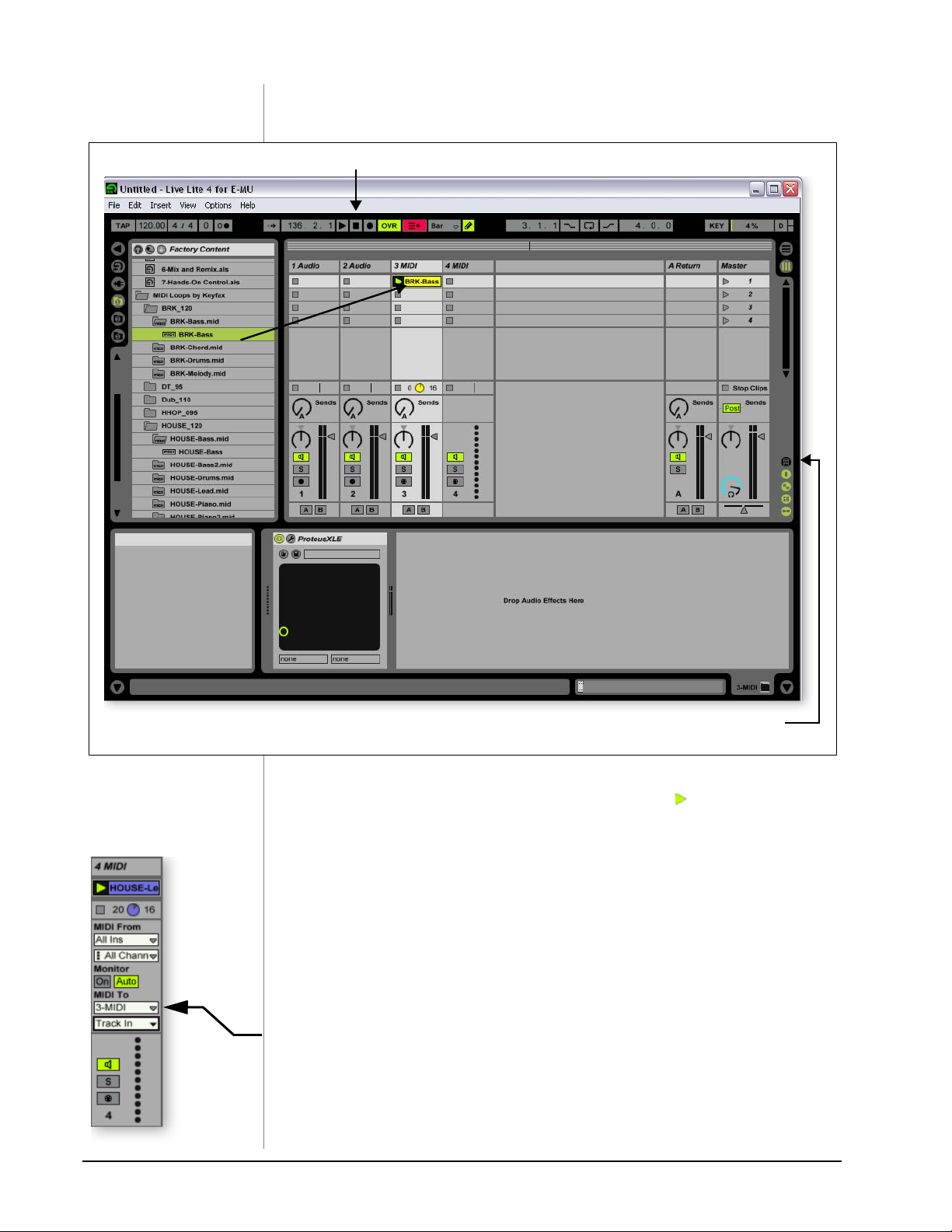
14. Locate MIDI Loops by Keyfax in the Factory Content section of the Ableton
Live Lite 4 Browser.
15. Click on the folder to open it. You’ll see a bunch of other folders.
16. Open the first folder, BRK_120. Next, open the next folder BRK-Bass.mid.
Now, you’ll see a MIDI file named BRK-Bass.
Step 14:
Locate MIDI Loops
0404 USB 2.0 Owner’s Manual 43
Page 44
Tutorials
17. Click and drag BRK-Bass over one of the clip slots in the 3 MIDI strip as
shown below.
Stop
Select
3-MIDI
Show/Hide In/Out Section
18. Now click on the Clip Launch Button (little triangle) on the MIDI clip you
just dragged over. The MIDI bass loop begins playing the bass preset on
Proteus VX. To stop playing, press the Stop button.
19. Find some other MIDI loops and drop them into the other slots of the track.
Hint: look in different folders. Click on the Clip Launch Buttons to switch
between clips.
Add Another MIDI Track
Ableton Live Lite 4 allows four MIDI tracks, so let’s play a different MIDI loop and
sound on track 4 MIDI.
20. Choose a different MIDI loop such as House-Lead, (located in the HOUSE-
120 folder) and drop it onto one of the 4 MIDI clip slots.
21. Currently, the MIDI To box reads “No Output”. Instead, select 3-MIDI.
Another option box labeled “Track In” now appears beneath 3-MIDI.
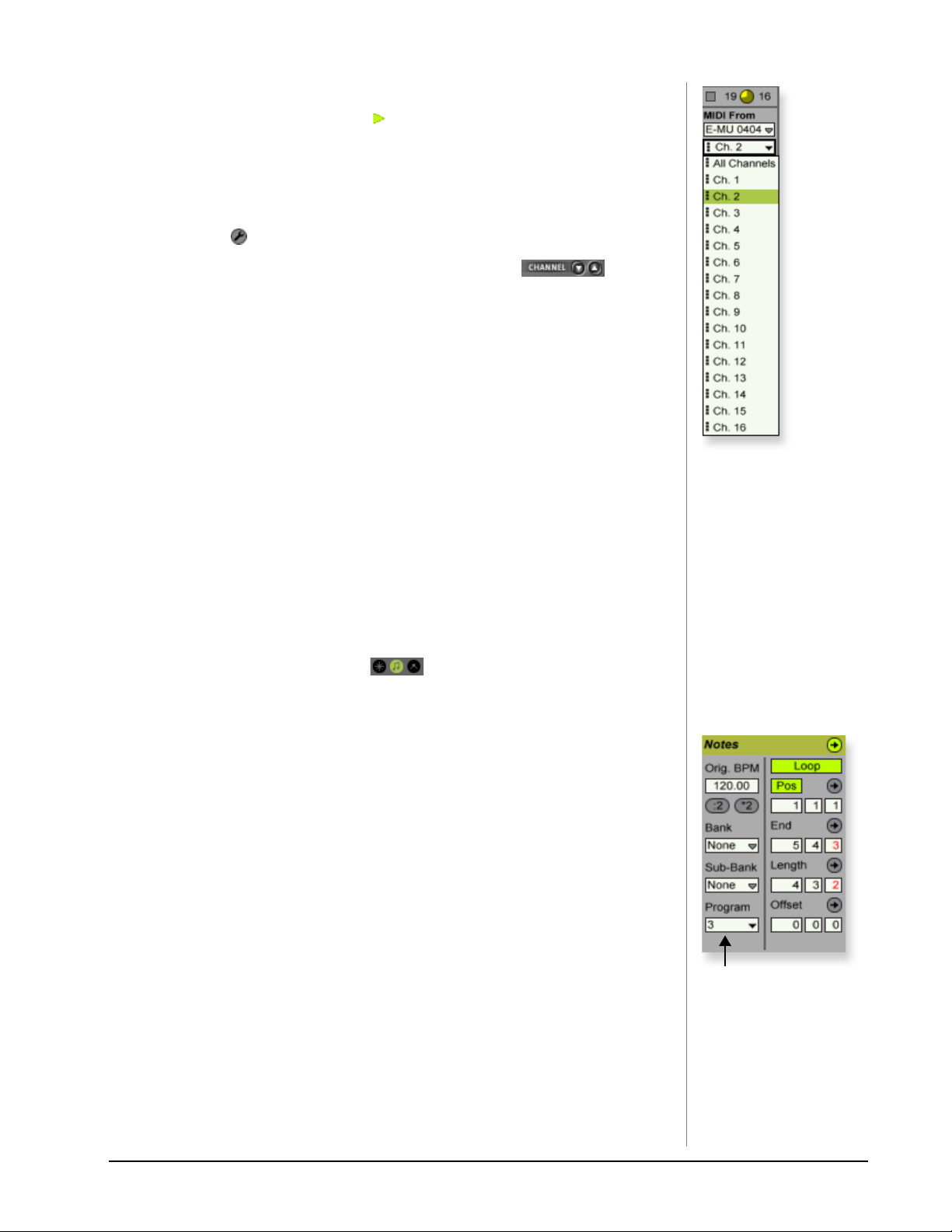
22. Click on the Track In box to see the list of MIDI channels.
44 E-MU Systems
Page 45
Tutorials
23. Select MIDI Channel 2 as shown at right.
24. Click on the Clip Launch Button on the 4 MIDI clip to get it started. You
won’t hear anything because you haven’t yet assigned a preset to MIDI
channel 2 on Proteus VX.
Choose a Sound for MIDI Channel 2
25. Click on the 3 MIDI heading to show the Proteus VX VSTi. Next, click on the
wrench icon again (in the MIDI Track View) to open Proteus VX.
26. Select MIDI Channel 2 using the channel inc/dec keys .
27. Select a Preset on Channel 2. Place the cursor in the preset number field and
use the up/down arrow keys on your computer keyboard to scroll through the
list until you find a preset you like.
• Note: There are several ways to select presets. See the Proteus VX Operation
manual for details.
28. Now you should be hearing the sound you chose on channel 2. If not, check
to make sure both clips are playing (green triangle). Each clip plays a different
preset.
Add MIDI Clips
29. Drop a few more MIDI clips into both MIDI channel slots. Play around with
the Clip Launch buttons.
Preset Change
Here’s another way to change the MIDI Program (Preset in E-MU speak) without
going into the Proteus VX editor.
30. Double-click on one of the currently playing MIDI clips. The Clip View
appears at the bottom of the window.
31. Select the Show/Hide Notes Box located in the lower left corner of
the Clip View window. The Notes box appears in the Clip View section.
32. Select a Program number. You’ll hear the Proteus VX sound change. Keep
selecting until you find one you like.
• Hint: Use the Up/Down Arrow keys to select Programs. Use Sub-Banks 2-8
to select presets higher than 128.
33. As an added bonus of selecting programs this way, the program (sound) you
selected is now associated with the MIDI clip. Whenever you select this MIDI
clip, the sound will also be selected.
34. Select another clip and assign a different program number. Notice that the
Preset changes when you switch back and forth between clips.
Save the Set
35. Save your work by selecting Save Live Set As… from the File menu. The next
time you load the set, the Proteus VX bank will automatically load as well.
Record a MIDI Track using your MIDI Keyboard
NOTE
Proteus VX sounds are
called Presets or Programs.
Ableton Live Programs are
offset by +1 from Proteus
VX.
Notes Box
Select
Preset
36. You can use the MIDI Track you set up on MIDI channel 2. Make sure there is
at least one empty slot in the MIDI track. (Select and hit backspace to delete a
clip.)
0404 USB 2.0 Owner’s Manual 45
Page 46

Tutorials
37. Set up the MIDI track as shown at left.
a. Select the 0404|USB in the “MIDI from” field.
b. Set the input to listen to MIDI channel 2.
c. Monitor should be set to Auto.
d. This field routes the MIDI data to track 3 (which contains Proteus VX).
e. Set the output to MIDI channel 2.
f. Turn record On (red).
38. Set your MIDI Keyboard to transmit on MIDI channel 2.
39. Play the keyboard. You should hear Proteus VX playing the last sound you
selected on channel 2. Go ahead and change the sound if you wish. (Doubleclick the top of Track 3, then click the Wrench icon on the Device Title Bar.
Make sure you’re changing the sound on channel 2.)
Ready to Record
a
b
c
d
e
40. Start up the bass line on track 3 MIDI and practice playing along with it.
41. Optional: You can set the Global Quantization value to time correct your
playing. Set it to anything other than “None”.
Quantize
42. Click one of the round MIDI Clip Record buttons to begin recording.
43. Click the Clip Launch button, the Clip Stop button, or the Spacebar to stop
recording.
f
On Your Own
Now you’ve had a taste of what Proteus VX and Ableton Live Lite 4 can do. But
don’t stop now! Read the Proteus VX Operation Manual pdf to learn all about this
exceptional instrument.
Ableton Live Lite 4 includes several excellent hands-on tutorials to help you learn
all the features of this ground-breaking music application.
Other Cool Tips
• To control Proteus VX with the knobs on your MIDI keyboard:
Go to the MIDI Preferences on Proteus VX (Options, Preferences, Controllers
tab) and make sure the MIDI Continuous Controller numbers match the ones
your keyboard is sending. You can change the controller numbers on either
your MIDI keyboard or Proteus VX, just as long as they both match.
• To control Proteus VX with the Assignable X/Y Controls in Live:
Simply select the Proteus VX Channel and Proteus VX controller letter A-M for
each axis of the X/Y controller. Open Proteus VX to see what controllers A-M
are controlling. For more information about MIDI controllers please refer to
the Proteus VX pdf manual.
Assign Controllers
46 E-MU Systems
Page 47

Using Dolby AC-3 Pass-through
USING DOLBY AC-3 PASS-THROUGH
The coaxial or optical digital output of the E-MU 0404 USB 2.0 can pass Dolby
AC-3 encoded 5.1 surround sound audio from your computer to an AC-3 decoder
such as a surround sound AV receiver. This feature allows you to watch DVDs on
your computer and enjoy 5.1 surround sound.
To utilize this feature you’ll need:
• DVD playback software that supports Dolby Digital 5.1
(such as WinDVD for the PC or DVD Player on the Mac)
• An AC-3 decoder such as an AV receiver or preamplifier.
• A surround sound playback system.
To Listen to a DVD in 5.1 Surround Sound
1. Connect the S/PDIF coaxial or optical output of the 0404 USB 2.0 to the
digital input of your AC-3 receiver.
WinDVD
2. Make sure the 0404 USB 2.0 is the Default Sound Playback Device” in the
“Sounds and Audio Devices” Control Panel on your PC.
3. Setup your DVD software to, “Output digital S/PDIF to external processor.”
Mac DVD Player
4. Select Preferences... located under DVD Player on the Menu Bar.
5. Select the Disc Setup tab.
6. Select Digital Out - E-MU 0404 USB 2.0 as the Audio Output.
7. Click OK
Receiver
0404 USB 2.0 Control Panel
8. Set your AV receiver to input from the
proper digital input.
9. Play the DVD. You should be hearing
audio through your system.
10. When the 0404 USB 2.0 is receiving
AC-3, the Direct Monitor and S/PDIF
LEDs will NOT be lit. In addition the
Sample Rate and Sync Source fields in
the Control Panel application will be
greyed out. Otherwise, the 0404 USB
2.0 is not receiving valid AC-3.
TIP . . .
If you don’t get AC-3
passthrough, turn off the
DVD player, then set the
sample rate of the 0404
USB to match the sample
rate of the DVD (usually
48kHz).
0404 USB 2.0 Owner’s Manual 47
Page 48

Troubleshooting
TROUBL ESHOO TING
Can’t hear Windows Media Player in Windows
If you have, or ever have had, another audio device installed in your PC, you may
have to set the E-MU 0404 USB 2.0 as the “Default Audio Device”.
1. Open the Control Panel, then select Sounds and Audio Devices.
2. Click the Audio tab and select the E-MU 0404 USB 2.0 as the Default device
under Sound Playback.
3. Click the Volume button under Sound Playback and turn up Wave volume.
You cannot record or monitor ASIO and WAVE at the same time. The first audio
application you open controls the E-MU 0404 USB 2.0.
Lost Communication
Should you lose communication between your E-MU 0404 USB 2.0 and an audio
application (Ableton Live, Cubase, Sonar, etc.), the E-MU 0404 USB 2.0 drivers
may need to be re-selected in your application.
1. Go to your application's I/O settings, de-select the E-MU 0404 USB 2.0 for
both input and output.
2. Apply these changes and exit the dialog.
3. Re-enter the application's preference settings and re-select the E-MU 0404 USB
2.0 drivers. If this doesn’t work, the application may need to be restarted.
Ground Loops
In digital audio devices and computers, audio ground loops may appear as pitched
tones, digital hash in the background, as well as the familiar 60 cycle hum.
Ground loops are caused by a difference in ground potential between two pieces of
equipment. Computer audio devices are particularly susceptible to ground loops
because most computers were not designed with high quality audio in mind.
The E-MU 0404 USB 2.0 contains built-in “ground lift” switches for both analog
inputs in order to safely break the loop if a ground loop occurs in your setup.
No Input Ground
A-GND LIFT
B-GND LIFT
Grounded Input
The ground-lift switches are located on the bottom of the unit, close to the front
panel. The input ground is lifted when the A or B slide switch is closest to the GND
LIFT label.
Pops & Crackles
Pops and crackling noises in the audio are most often caused by having the ASIO
Buffer Size set too low. Adding audio tracks and VST plug-ins increases the load on
your computer’s CPU. If your computer cannot keep up with all the tasks you are
asking it to perform, pops and crackles may occur. In effect, increasing the ASIO
buffer gives your computer “more time” to complete its assigned tasks. The
hardware Direct Monitor feature of the 0404 USB 2.0 allows you to increase the
ASIO Buffer setting without the associated latency problems during recording and
overdubbing.
USB hubs can create problems with digital audio and should be avoided whenever
possible.
48 E-MU Systems
Page 49

Troubleshooting
No S/PDIF I/O (OS X)
S/PDIF is not available at the 88.2/96 kHz sample rates. When these higher sample
rates are selected in the OSX Audio MIDI Setup, 2-channel mode is automatically
selected. When you switch the sample back to 44.1/48 kHz, 2-channel mode
remains in effect. To remedy the situation:
1. Click Go -> Utilities from the menu bar.
2. Double-click Audio MIDI Setup.
3. Select the 44.1/48 kHz sample rate and select 4-ch-24bit for the Audio Input
and Audio Output.
Simultaneous WDM/ASIO/AC-3 Playback (Windows only)
The 0404 USB 2.0 only supports playing back 1 stream format at a time. Each of
the 3 mentioned stream types has a priority associated with it. If a higher priority
stream type is opened while a lower priority stream is already playing, the lower
priority stream will stop playing. The stream priorities, from highest to lowest, are
AC-3, ASIO, WDM.
USB 2.0 vs. USB 1.1 Operation (Windows only)
The 0404 can operate in USB 2.0 or USB 1.1 mode. 96 kHz and 192 kHz sample
rates are only available while operating in USB 2.0. The included E-MU USB Audio
Control panel software includes an indicator to let the user know which mode the
device is running in.
0404 USB comes up in USB 1.1 mode (Windows only)
Always turn the 0404 USB power off before connecting or disconnecting the USB
cable. Hot-plugging the unit with the power on can cause the 0404 to power-up in
USB 1.1 mode. If you see the Windows message, "This device could perform
faster…", simply turn power off, wait a few seconds, then turn power on again.
0404 USB 2.0 Owner’s Manual 49
Page 50

Troubleshooting
Internet References
The internet contains vast resources for the computer musician. A few useful sites
are listed here, but there are plenty more. Check it out.
Software Updates, Tips & Tutorials . http://www.emu.com/support
Setting up a PC for Digital Audio .... http://www.musicxp.net
MIDI Basics.......................................... Search for “MIDI Basics” (many sites)
MIDI & Audio Recording................... http://www.midiworld.com
MIDI & Audio Recording................... http://www.synthzone.com
Sonar Users Group............................ http://www.cakewalknet.com/index.php
Cubase, ASIO & Digital Audio.......... http://www.steinberg.net
ASIO, Cubase & Digital Audio.......... http://www.steinbergusers.com/cubasele/
le_support.php
Cubase Users Group .......................... http://www.groups.yahoo.com/group/
cubase/messages
Forums
Unofficial E-MU Forum..................... http://www.productionforums.com/emu
Sound-On-Sound Forum .................. http://www.soundonsound.com
Computer Music Forum .................... http://www.computermusic.co.uk/main.asp
Home Recording Forum.................... http://homerecording.com/bbs
Studio Central Forum ........................ http://www.tweakheadz.com
KVR Forum .......................................... http://www.kvr-vst.com/forum/search.php
MIDI Addict Forum ........................... http://forum.midiaddict.com/search.php
Sound Card Benchmarking............... http://audio.rightmark.org
Driver Heaven Forum ........................ http://www.driverheaven.net
50 E-MU Systems
Page 51

Technical Specifications
TECHNICAL SPECIFICATIONS
General
Sample Rates: 44.1, 48, 88.2, 96, 176.4, 192kHz from internal crystal with no
sample rate conversion.
(Note: 176.4k & 192k sample rates not supported on Macintosh)
Bit Depth: 24-bit I/O, 32-bit processing
USB 2.0 Hi-Speed
Full 24-bit resolution at all sample rates
4in/4 out channels from 44.1-96kHz
2 in/2 out channels from 176.4-192kHz (MIDI disabled at 176.4-192kHz)
Zero-latency direct hardware monitoring (Disabled at 176.4/192kHz)
ASIO2, WDM MME, Apple Core Audio and Core MIDI drivers
AC3 and DTS Passthru supported
Anti-Pop speaker protection minimizes noise during power on/off
Ultra-low jitter clock subsystem
<500ps RMS in PLL mode (48kHz, Coaxial S/PDIF Sync)
Combo Microphone Preamplifier/Hi-Z/Line Inputs (2)
Type: E-MU XTC™ combo mic preamplifier and Hi-Z/line input w/ Soft Limiter
A/D converter: AK5385A
Gain Range: +60dB
Frequency Response: (min gain, 20Hz-20kHz) +0.0/-0.16dB
Stereo Crosstalk: (1kHz min gain, -1dBFS) < -110dB
Hi-Z Line Input
Input Impedance: 1Mohm
Max Level: +12dBV (14.2dBu)
Dynamic Range: (A-weighted, 1kHz, min gain) 113dB
Signal-to-Noise Ratio: (A-weighted, min gain) 113dB
THD+N: (1kHz at -1dBFS, min gain) -101dB (.0009%)
Microphone Preamplifier
Input Impedance: 1.5Kohms
Max Level: +6dBV (+8.2dBu)
EIN: (20Hz-20kHz, 150ohm, unweighted) -127dBu
Signal-to-Noise Ratio: (A-weighted, min gain) 112.5dB
THD+N: (1kHz at -1dBFS, min gain) -101dB (.0009%)
Phantom Power: 48V
Soft Limiter: 5dB max compression (software selectable)
0404 USB 2.0 Owner’s Manual 51
Page 52

Technical Specifications
Analog Line Outputs (2)
Type: balanced, AC-coupled, 2-pole low-pass differential filter
D/A converter: AK4396
Level (auto detect):
Professional: +12dBV max (balanced)
Consumer: +6dBV max (unbalanced)
Frequency Response: (20Hz - 20kHz) 0.06/-.035dB
Dynamic Range: (1kHz, A-weighted) 117dB
Signal-to-Noise Ratio: (A-weighted) 117dB
THD+N: (1kHz at -1dBFS) -100dB (.001%)
Stereo Crosstalk: (1kHz at -1dBFS) < -114.5dB
Headphone Amplifier
Type: Class-A power amplifier
D/A converter: AK4396 (shared with Line Out)
Gain Range: 60dB
Maximum Output Power: 20mW
Output impedance: 22 Ohms
Frequency Response: (20Hz–20kHz) +0.06/-0.035dB
Dynamic Range: (A-weighted) 114dB
Signal-to-Noise Ratio: (A-weighted) 114dB
THD+N: (1kHz, max gain): 600ohm load -95.5dB (.0018%)
Stereo Crosstalk: (1kHz at -1dBFS, 600 ohm load) < -85dB
Digital I/O
S/PDIF
2 in/2 out coaxial (transformer coupled)
2 in/2 out optical
AES/EBU or S/PDIF format (software selectable)
MIDI
1 in, 1 out
Synchronization
Internal crystal sync at: 44.1, 48, 88.2, 96, 176.4, 192kHz
External sample rate sync via:
Optical S/PDIF (44.1 – 96kHz)
Coaxial S/PDIF (44.1 – 96kHz)
Weight / Dimensions
Weight: 1.685 lb / 0.764kg
Dimensions: W: 7.25” (184 mm) H: 2.0” (50.8 mm) L: 7.0” (177.8 mm)
52 E-MU Systems
Page 53

Declaration of Conformity
DECLARATION OF CONFORMITY
Trade N a m e: E-MU Systems
Model No.: EM8761
Responsible Party: E-MU Systems
Address: 1500 Green Hills Road, Suite 101
Scotts Valley, CA 95066 U.S.A.
This device complies with Part 15 of the FCC rules. Operation is subject to the
following two conditions: (1) This device may not cause harmful interference, and
(2) this device must accept any interference received, including interference that
may cause undesired operation.
CAUTION
You are cautioned that any changes or modifications not expressly approved in
this manual could void your authority to operate this equipment.
Note:
This equipment has been tested and found to comply with the limits for a Class B
digital device, pursuant to Part 15 of the FCC Rules. These limits are designed to
provide reasonable protection against harmful interference in a residential installation. This equipment generates, uses, and can radiate radio frequency energy
and, if not installed and used in accordance with the instructions, may cause
harmful interference to radio communications. However, there is no guarantee
that interference to radio or television reception, which can be determined by
turning the equipment off and on, the user is encouraged to try to correct the interference by one or more of the following measures:
• Reorient or relocate the receiving antenna.
• Increase the separation between the equipment and receiver.
• Connect the equipment into an outlet on a circuit different from that to
which the receiver is connected.
• Consult the dealer or an experienced radio/TV technician for help.
The supplied interface cables must be used with the equipment in order to comply
with the limits for a digital device pursuant to Subpart B of Part 15 of FCC Rules.
0404 USB 2.0 Owner’s Manual 53
Page 54

Declaration of Conformity
Compliance Information
United States Compliance Information
FCC Part 15 Subpart B Class B using:
CISPR 22 (1997) Class B
ANSI C63.4 (2001) method
FCC Site No. 958979
Canada Compliance Information
ICES-0003 Class B using:
CISPR 22 (1997) Class B
ANSI C63.4 (2001) method
Industry of Canada File No. IC 5933
European Union Compliance Information
EN55024 (1998 w/A1:01 & A2:03)
EN55022 (1998) Class B
Australia/New Zealand Compliance Information
AS/NZS CISPR 22 (2002) Class B using:
EN55022 (1998) Class B
Japan Compliance Information
VCCI (April 2000) Class B using:
CISPR 22 (1997) Class B
ANSI C63.4 (2001) method
VCCI Acceptance Nos. R-2160 & C-2332
Attention for the Customers in Europe
This product has been tested and found compliant with the limits set out in the
EMC Directive for using connection cables shorter than 3 meters (9.8 feet).
Notice
If static electricity or electromagnetism causes data transfer to discontinue midway
(fail), restart the application or disconnect and connect the USB cable again.
54 E-MU Systems
Page 55

Index
INDEX
Numerics
48V On Switch & LED
5 Volt DC Power Jack
5.1 Surround Sound, passthrough
60 Cycle Hum, eliminating
A
Ableton Live Lite 4 for E-MU
changing presets
playing MIDI clips
running Proteus VX in
setting up
Ableton Live Lite 4, tutorial
AC-3 Passthrough
Add Track, Cubase LE
Analog to S/PDIF Converter
ASIO Buffer Latency
38
15
17
48
45
43
42
38
47
26, 28
19
23, 31
47
Devices
Devices Menu, Cubase LE
Digital Input Status
Direct Monitoring
Dolby AC-3
DVD, playing
E
E-Control Application
E-MU ASIO
External Sync to S/PDIF
External Synchronization
G
Ground Lift Switches
Ground Loops
Guitar, connecting
H
Headphone Level Control
Headphone Output
Hum, eliminating
26
19
21
controls
vs software monitoring
14
47
47
18
Cubase LE
Sonar LE
23
30
19
48
48
16
16
48
23
21
19
15
B
Balanced Cables
Blinking External Sync LED
C
Clicks & Pops, cause
Clip Indicators
Computer Requirements
Connection Diagram
Continuous Controller numbers
Control Panel
Controls
Cubase LE
D
Device Select, E-Control
Device Setup, Cubase LE
14
project window
setting up
tutorial
16
20
20
15
7
12
23
22
22
22
18
23
46
I
Input Level Controls
Input/Output
Inspector, Cubase LE
L
Latency
Lock Indicator
Lost Communication
M
MIDI
activity indicators
channels, using multiple
clips, Ableton Live
connection
continuous controller numbers
in/out jacks
16
21
adding
playing
Cubase LE
Sonar LE
15
27
19
48
14
45
43
27
35
17
28, 36, 45
46
0404 USB 2.0 Owner’s Manual 55
Page 56

Index
track
adding in Ableton Live Lite
recording in Cubase LE
recording in Sonar LE
Monitor Button, Cubase LE
Monitoring, direct
Monitoring, direct vs software
Mono Switch
Multitrack Recording
Cubase LE
Sonar LE
O
Options Menu, Sonar LE
Output Level Control, 0404
Outputs
P
Package Contents
Playing Audio Clips, Ableton Live Lite
Pops & Crackles
Power Switch
Preset Changes, Ableton Live Lite
Project Window, Cubase LE
Proteus VX
Proteus X Composer Bank, loading
R
Recording Audio
Recording MIDI
17
application window
using with Ableton Live Lite
using with Cubase LE
using with Sonar LE
Ableton Live Lite
into Cubase LE
into Sonar LE
Cubase LE
Sonar LE
21
14
24
32
8
20, 48
17
41
24
32
26
34
24
30, 31
14
22
35
26
34
44
28
36
21
45
42
43
40
Signal Level Indicators
Simultaneous WDM/ASIO/AC-3 Playback
Skin, selecting
Soft Limit Control
Software Installation
Mac OSX
Windows XP
Sonar LE
multitrack recording
project window
Sub-Bank, Ableton Live Lite
Surround Sound
Sync Status Indicators
Synchronizing
using external clock
T
Technical Specifications
Track Record Enable Button, Sonar LE
Troubleshooting
Tutorials
Ableton Live Lite 4
Cakewalk Sonar LE
Proteus VX with Ableton Live Lite
Proteus VX with Cubase LE
Proteus VX with Sonar LE
Steinberg Cubase LE
U
Uninstalling Drivers & App
USB 1.1 port
USB 1.1 Warning Message
USB 2.0 vs. USB 1.1 Operation
USB Jack
V
VST Instruments
VST Plug-ins, locating in Ableton Live Lite
18
9
19, 20
22
17
17
15
19
8
32
32
45
47
14, 20
19
51
32, 37
48
38
29
42
26
29
22
8, 11
49
49
26
49
38
S
S/PDIF
description
in/out
mode button
output format
S/PDIF to Analog Converter
Save Live Set, Ableton Live Lite
Save Project, Sonar LE
56 E-MU Systems
19
16
15
19
19
45
33
W
WDM/ASIO/AC-3 Playback
Windows Logo Testing Note
Windows Media Player, no audio
X
X/Y Controller, Ableton Live Lite
49
8
48
46
 Loading...