

Page 1
Quick Start Guide
Quick Start Guide
0404
Quick Start Guide - 0
Page 2
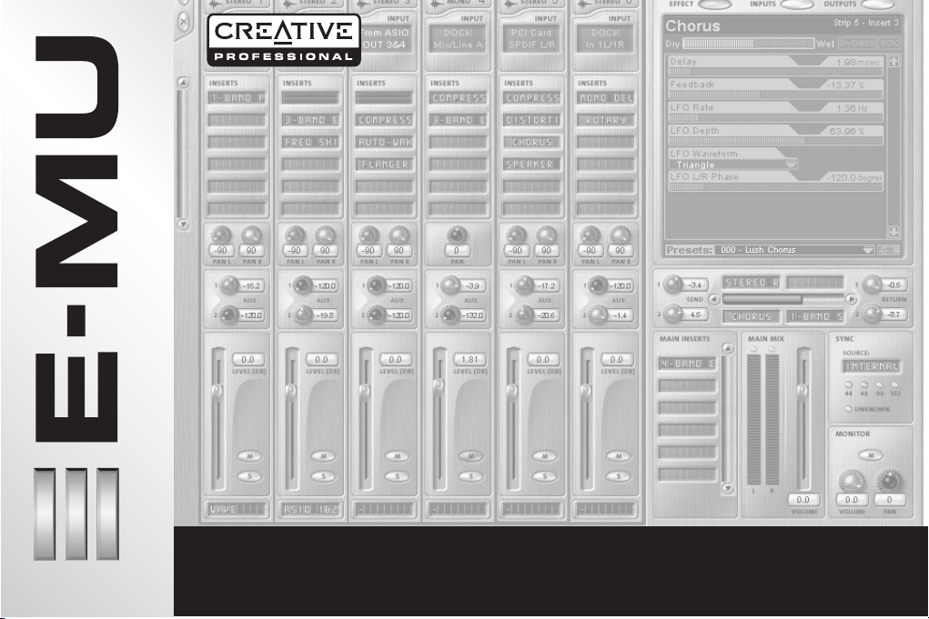
Creative Professional
1- Introduction
Thank you for purchasing the E-MU 0404 Digital Audio System. We’ve designed this E-MU Product to be logical, intuitive
and above all, to provide you with pristine sound quality. This audio interface features studio-quality, 24-bit/96kHz multichannel recording and playback and built-in, hardware-based effects, S/PDIF (coaxial & optical) digital interface, as well as
MIDI I/O.
System Requirements
• Genuine Intel® Pentium® III, AMD® K6® class processor operating at 500 MHz or faster
• Intel, AMD or 100% compatible motherboard & chipset
• Windows 2000 SP4, or Windows XP SP1
• 128 MB RAM
• 500 MB of free hard disk space for full installation.
• Available PCI 2.1 compliant slot (Two slots needed for E-MU 0404 and Sync Daughter Card)
• XVGA Video (1024 x 768)
• CD-ROM drive required for software installation.
• Headphones or amplified speakers
Other applications may have higher system requirements.
Package Contents
E-MU 0404
• E-MU 0404 PCI card
• (1) Digital Breakout Cable
• (1) Analog Breakout Cable (1/4”)
• E-MU Digital Audio Systems Software/Driver Installation CD-ROM
• Owner’s Manual (on CD)
• Quick Start guide
1 - E-MU 0404 Digital Audio System
Page 3

Safety First!
As you install hardware components, observe the following general precautions to avoid damage to your equipment and
yourself.
• To avoid possible permanent damage to your hardware, make sure that all connections are made to the E-MU 0404
card with the host computer’s power off.
• Unplug the computer’s power cable to make sure that the computer is not in sleep mode.
• Take care to avoid static damage to any components of your system. Internal computer surfaces, the E-MU 0404 PCI
board and the interfaces are susceptible to electrostatic discharge, commonly known as “static”. Electrostatic discharge can damage or destroy electronic devices. Here are some procedures you can follow when handling electronic devices in order to minimize the possibility of causing electrostatic damage:
• Avoid any unnecessary movement, such as scuffing your feet when handling electronic devices, since most movement can generate additional charges of static electricity.
• Minimize the handling of the PCI card. Keep it in its static-free package until needed. Transport or store the board
only in its protective package.
• When handling a PCI card, avoid touching its connector pins. Try to handle the board by its edges only.
• Before installing a PCI card into your computer, you should be grounded. Use a ground strap to discharge any static
electric charge built up on your body. The ground strap attaches to your wrist and any unpainted metal surface
within your computer.
• Before connecting a cable to your interface or between PCI cards, touch the connector sleeve of the cable to the
sleeve of the jack to which you’ll be connecting the cable in order to discharge any static build-up.
Getting More Information
Refer to the various online Help files and the Owner’s Manual (on CD) for detailed information on the E-MU Digital Audio
System and various software applications.
Technical Support
As the E-MU Digital Audio System expands, you’ll want to keep up with the latest software and new options for your E-MU
Digital Audio System. You can find all of this—plus other helpful information—at www.emu.com. Refer to your Owner’s
Manual on CD for the technical support phone number.
Quick Start Guide - 2
Page 4
2 - Hardware Installation
Creative Professional
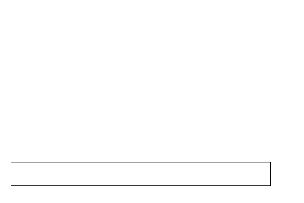
Metal brackets
PCI slots
ISA slots
Step 1: Prepare your Computer
1. Turn off your computer and all peripheral devices.
2. Touch a metal plate on your computer to ground yourself and to discharge any static electricity, and then unplug the power cord from the wall outlet.
3. Remove the computer cover.
4. Remove the metal bracket from any available PCI slot. If you are installing a Sync Card as
well, remove the bracket from two adjacent PCI slots. See the figure at left.
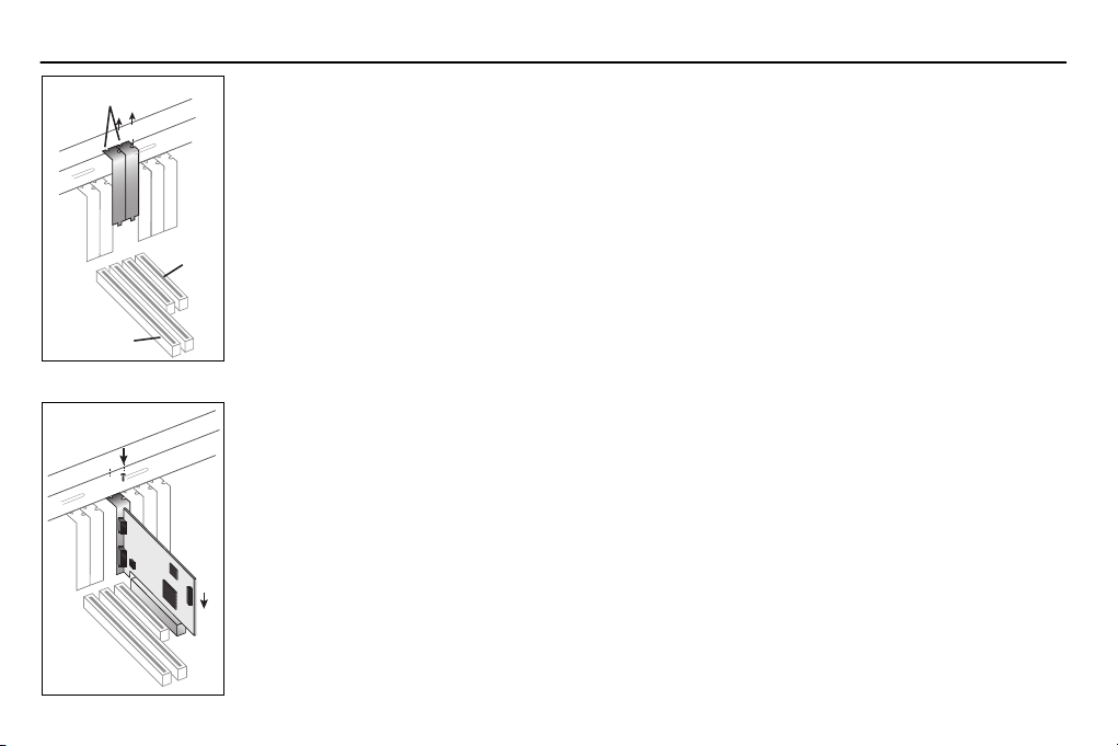
Step 2: Install the E-MU 0404 PCI card
1. Align the E-MU 0404 PCI card with the slot and press gently but firmly down into the slot as
shown in the figure opposite.
2. Do not force the E-MU 0404 card into the slot. Make sure that the gold finger connector of
the card is aligned with the PCI bus connector on the motherboard before you insert the
card into the PCI slot. If it doesn’t fit properly, gently remove it and try again.
3. Secure the card to the slot using a screw (if necessary).
3 - E-MU 0404 Digital Audio System
Page 5

Step 3 - How to Install the E-MU Sync Daughter Card
Note:
These steps are for E-MU Sync Daughter Card owners only, otherwise skip to step 4 below.
1. Connect the ribbon cable provided with the kit between the E-MU 0404 card and the Sync Daughter Card as shown in
figures below. The cable is keyed so it cannot be incorrectly inserted. Seat the connectors firmly in the sockets and
arrange the cable neatly.
2. Secure the E-MU Sync Card into the slot next to the E-MU 0404 card using a second screw (if necessary).
E-MU Sync Daughter Card
(Optional)
Step 4 - Close the Computer
1. Replace the cover to your computer.
2. Plug the power cord and your peripheral devices into your computer and turn on your computer.
Quick Start Guide - 4
Page 6

3 - Software Installation
Creative Professional
Installing and Uninstalling the E-MU 0404 Drivers and Applications
The first time you restart your PC after installing the E-MU 0404 PCI card, you will need to install the Patchmix DSP software
and E-MU 0404 PCI card drivers.
Windows 2000 or Windows XP
1. After you have installed your audio card, turn on your computer. Windows automatically detects your audio card and
searches for device drivers.
2. When prompted for the audio drivers, click the
3. Insert the E-MU Digital Audio Systems Software/Driver Installation CD-ROM into your CD-ROM drive.
If Windows AutoPlay mode is enabled for your CD-ROM drive, the CD starts running automatically. If not, from your
Windows desktop, click
CD-ROM drive). You can also simply open the CD and double-click
4. The installation splash screen appears. Follow the instructions on the screen to complete the installation.
5. Choose “Continue Anyway” when you encounter the “Windows Logo Testing” warning screen.
6. When prompted, restart your computer.
Start->Run
(The software is not compatible with other versions of Windows.)
and type
Cancel
d:\ctrun\ctrun.exe
button.
(replace
Ctrun.exe
d:\
with the drive letter of your
located in the CTRun folder.
(Info on last page.)
Uninstalling all Audio Drivers and Applications
At times you may need to uninstall or reinstall some or all of the audio card's applications and device drivers to correct problems, change configurations, or upgrade outdated drivers or applications. Before you begin, close all audio card
applications. Applications still running during the uninstallation will not be removed.
1. Click
2. Double-click the
3. Click the
4. Select the E-MU 0404 PCI card entry, or the application entry and then click the
5. In the
6. Click the
7. Restart your computer when prompted.
8. You may now re-install existing or updated E-MU 0404 PCI card device drivers or applications.
5 - E-MU 0404 Digital Audio System
Start
->
Settings
Install/Uninstall
InstallShield Wizard
Yes
button.
->
Add/Remove Programs
Control Panel
tab (or
dialog box, select the
.
Change or Remove Programs
icon.
Remove
option.
button).
Add/Remove
button.
Page 7

4 - E-MU 0404 PCI Card
The E-MU 0404 PCI card contains E-MU’s powerful E-DSP chip. The powerful hardware DSP on this card leaves more power
free on your CPU for additional software plug-ins and other tasks.
Connections
ANALOG
DIGITAL
Connect to
Analog
Breakout Cable
Connect to
Digital
Breakout Cable
Analog
Connector
Digital Audio
& MIDI
Connector
(MIDI & S/PDIF)
Connect the analog breakout cable to the PCI Card.
• Connect the supplied 1/4” jack breakout cable to the analog connections of your
audio system or mixer. See diagrams on the followng pages.
Connect the digital breakout cable, which provides MIDI In & Out and S/PDIF In & Out
(2-channels optical or coaxial) to the PCI Card.
• MIDI input and output ports allow you to interface any type of MIDI equipment
such as keyboards, effect units, drum or guitar controllers. The MIDI drivers were
installed when you installed your PatchMix DSP software and the MIDI ports will
appear in your system control panel under “Sounds and Audio Devices”.
• S/PDIF digital I/O can be used for the reception and/or transmission of digital
data from external digital devices such as a DAT machine, an external analog-todigital converter or an external signal processor equipped with digital inputs and
outputs.
S/PDIF can be transmitted and received via the RCA coaxial connectors or TOSLINK
optical connectors on the Digital Breakout Cable. Optical connections have certain
advantages such as immunity to electrical interference and ground loops. The optical
S/PDIF and RCA coaxial S/PDIF inputs cannot be used simultaneously, however both
S/PDIF outputs are available simultaneously (carrying the same signal).
The S/PDIF out can be configured in either Professional or Consumer mode with
24-bits of resolution. The S/PDIF input and outputs support 44.1kHz, 48kHz and
96kHz sample rates.
Quick Start Guide - 6
Page 8

Creative Professional
Analog Output Connections
Analog
Breakout
Cable
L
Out
R
7 - E-MU 0404 Digital Audio System
or...
Mixer
To Mixer Inputs
Amp
Aux Inputs on Home Stereo
Speakers
Volume
Integrated
Amplifier
& Speakers
Page 9

Analog Input Connections
Analog
Breakout
Cable
Audio Component
Mixer
In
L
R
Electronic Keyboard
REAL TIME CONTROLLERS
ASSIGNABLE KEYS
PRESET
SAMPLE
SEQUENCER
EMULATOR
Microphone
LEVEL
EXIT
ENTER
PAGE
PRESET SELECT
RETURN
0.987654321
Electric Instrument
Instr. Preamp
Quick Start Guide - 8
Page 10
Creative Professional
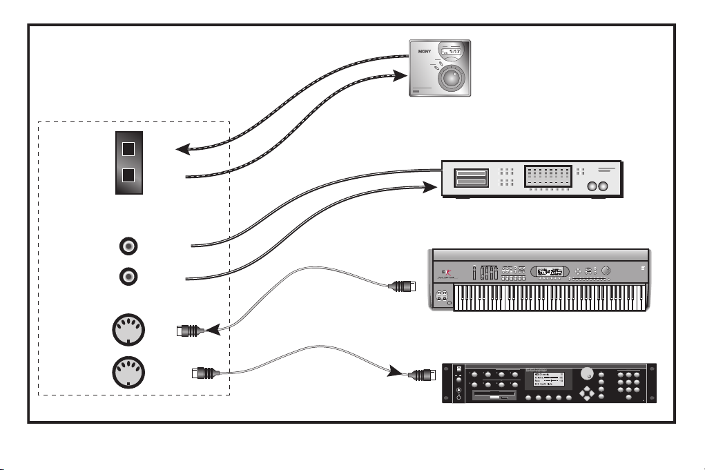
Digital Connections
Digital
Breakout Cable
S/PDIF
(Optical)
S/PDIF
(Coax)
MIDI
In
Out
In
Out
In
Out
Optical
Coaxial
MIDI Out
Out
Portable
Digital Recorder
In
DAT / CD / DVD
Any Digital Audio Device with S/PDIF
Out
In
MIDI Keyboard
REAL TIME CONTROLLERS
ASSIGNABLE KEYS
PRESET
SAMPLE
SEQUENCER
EMULATOR
MIDI Sound Module
SAMPLE
MASTER/GLOBAL
TRANSPOSE DIGITAL PROCESSINGSAMPLE MANAGEMENT
I
O
PRESET
MULTIMODE
PRESET MANAGEMENT DYNAMIC PROCESINGPRESET DEFINITION
MIDI In
VOLUME
DRIVE SELECT LOAD SAVE AUDITION TRIGGER MODE
LEVEL
EXIT
ENTER
PAGE
PRESET SELECT
RETURN
0.987654321
TRIGGERS
INC/YES
ABC
DEF
123
DEC/NO
JKL
MNO
GHI
456
ENTER
TUV
WXY
PRS
789
ESCAPE
QZ
0
MIDI
9 - E-MU 0404 Digital Audio System
Page 11

The E-MU Sync Card
(Optional Accessory)
The Sync Card provides Word Clock in and out, SMPTE (LTC) in and out and an additional MIDI output for transmitting MIDI
Time Code (MTC). MIDI Time Code is a special rendering of SMPTE that can be transmitted over MIDI cables.
Word Clock is a standard means of synchronizing two or more pieces of digital equipment at the system sample rate
(44.1kHz, 48kHz or 96kHz). To avoid data corruption, digital equipment MUST be synchronized to each other.
Recording equipment can also be synchronized using SMPTE or MTC sync so that two audio recorders or an audio and
video recorder can lock together as a single machine. For more information, please refer to your Owner’s Manual (on CD).
Connections
Word Clock In: Receives word clock (sample clock) from another digital device such
Word Clock Inputs
and Outputs
SMPTE In/Out
MTC Out
as a digital video deck, digital recorder or digital mixer.
Word Clock Out: Sends word clock (sample clock) to another digital recorder. Word clock
is always output, whether it is generated by the internal clock or passed through from
the word clock input.
The SMPTE Input converts incoming SMPTE longitudinal time code (LTC) to MIDI Time
Code (MTC) and passes this information to the host computer to be used by a sequencer
or audio recorder application. When your computer application is the “Master”, MTC
generated by the computer application is converted into SMPTE and sent out to another
SMPTE device such as another audio recorder to synchronize it with the sequencer.
This output transmits MIDI Time Code to another computer or audio recorder. The
source of the MTC can be from the sequencer or SMPTE in.
Quick Start Guide - 10
Page 12

Note about Windows™ Logo Testing:
The Digital Audio System drivers are not signed because the driver does not support some of the consumer audio features
that the Microsoft driver signing program requires, most notably Digital Rights Management.
However, the Digital Audio System drivers have been rigorously tested using the same test procedures that a signed driver
requires, and it passes in all important categories, including those that measure the relative stability of the driver. So, it is
perfectly safe to install these drivers on your computer.
Notice
Information in this document is subject to change without notice and does not represent a commitment on the part of
E-MU Systems, Inc. No part of this manual may be reproduced or transmitted in any form or by any means, electronic or
mechanical, including photocopying and recording, for any purpose without the written permission of E-MU Systems, Inc.
The software described in this document is furnished under a license agreement and may be used or copied only in accordance with the terms of the license agreement. It is against the law to copy the software on any other medium except as
specifically allowed in the license agreement. The licensee may make one copy of the software for backup purposes only.
E-MU is a registered trademark of E-MU Systems, Inc. in the United States and/or other countries.
Copyright © 2004 by E-MU Systems, Inc. All rights reserved.
Version 1.00
April, 2004
 Loading...