

Page 1

EAOM-210 FLJ.eng / ver 0.0
Pages 1 / 132
EAOM-210 FLJ
AUTOMATIC TRANSFER & SWITCHING UNIT
FOR DIESEL/GAS GENERATORS WITH J1939 FOR ECUs
User Manual
EMKO ELEKTRONIK A.S.
Demirtas Org. San. Bolg.
Karanfil Sk. No: 6 TR
16369 Bursa / TURKEY
Page 2

EAOM-210 FLJ.eng / ver 0.0
Pages 2 / 132
Section 1 Introduction .............................................................................................. 4
Section 2 Installation ............................................................................................... 7
2.1 Unit Configuration ...................................................................................................... 7
2.2 Mechanical Installation ................................................................................................ 7
Figure 2.3 Side view. ................................................................................................................................... 8
2.3 Electrical Connections.................................................................................................. 8
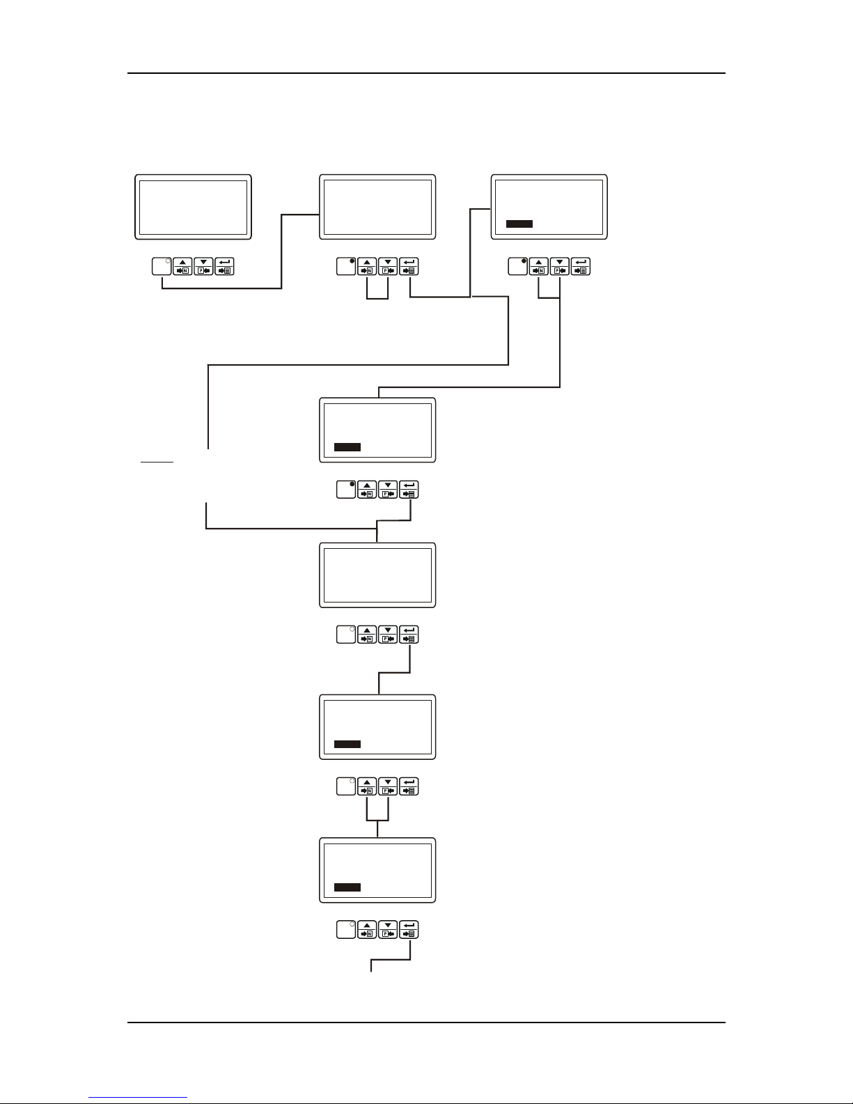
Figure 2.4 Rear view. .................................................................................................................................. 8
Figure 2.5 EAOM-210 FLJ three phase connections schematic. ......................................................... 10
Table 2.1 Unit wiring ................................................................................................................................. 12
Table 2.2 Unit wiring description ............................................................................................................ 14
Electronic Engines (ECUs) and EAOM-210FLJ unit............................................................................ 16
Section 3 Definition Of Front Panel And Programming.....................................................18
3.1 Front Panel Description ...............................................................................................18
3.2 Programming Procedure ..............................................................................................20
3.3 Accessing to the Operator Parameters............................................................................20
3.3.1 Changing and Saving Operator Parameter Values.................................................................. 22
3.4 Accessing to the Technician Parameters .........................................................................24
3.4.1 Changing and Saving Technician Parameter Values .............................................................. 33
3.5 Programmable function definitions ................................................................................35
3.6 Pc Interface ..............................................................................................................94
3.6.1 Technical Specifications............................................................................................................... 94
3.6.2 RS-232 Serial Interface, Programming The Device Over PC or Modem ............................ 94
3.6.2.1 Cable Connection Between RS-232 Terminal of the Device and PC.............................. 94
3.6.3 Installation Instruction ................................................................................................................. 94
3.6.3.1 Minimum system requirements .................................................................. 94
3.6.3.2 Installing EAOM-210 FLJ configuration software ............................................. 94
3.6.3.3 To Run EAOM-210 FLJ configuration software ................................................ 95
3.6.4 Description ...................................................................................................................................... 97
3.6.4.1 Main Menu........................................................................................... 97
File Menu.................................................................................................................................. 97
Window Menu .......................................................................................................................... 98
Program Menu ......................................................................................................................... 98
Observation Menu ................................................................................................................... 99
Operator Parameters Menu................................................................................................. 103
Technician Parameters Menu ............................................................................................. 104
Adjustment Page (Calibration) Menu ................................................................................ 106
Communication Settings Menu ........................................................................................... 106
Help Menu .............................................................................................................................. 107
Section 4 Commissioning ........................................................................................ 108
4.1 Manual operation.....................................................................................................108
4.2 Auto Operation ........................................................................................................ 109
4.3 Test Mode Operation ................................................................................................109
Section 5 Operation .............................................................................................. 110
5.1 Controls and Indicators ............................................................................................. 110
5.1.1 LCD Display Description: ............................................................................................................... 110
5.1.2 Failure Indicators Description: .................................................................................................... 123
Page 3

EAOM-210 FLJ.eng / ver 0.0
Pages 3 / 132
5.2 Mode transition .......................................................................................................124
5.3 Manual Start ...........................................................................................................124
5.4 Manual Stop ............................................................................................................ 124
5.5 Auto Operation ........................................................................................................ 124
5.6 Test Operation ........................................................................................................125
5.6.1 Exercise Function ........................................................................................................................ 125
Section 6 Fault Finding .......................................................................................... 126
6.1 General.................................................................................................................. 126
6.2 Error Messages ........................................................................................................ 126
Table 6.1 Fault finding ....................................................................................128
Section 7 Block Diagram......................................................................................... 129
Section 8 Specifications & Ratings ............................................................................ 130
Page 4

EAOM-210 FLJ.eng / ver 0.0
Pages 4 / 132
Section 1 Introduction
The EAOM-210 FLJ provides for automatic transfer of a load from mains to generator in the
event of a mains failure. Intended for unattended operation, it is able to detect failure of
any phase of the mains and to start and switch over to a generator if the mains voltage
goes outside pre-set limits. Both automatic and manual control is possible. A test mode is
also available which allows the generator to be run without taking the load.
The unit monitors J1939 ECU messages and provides remote start/stop control via J1939
protocol (supported ECUs: Volvo EMS2, Volvo EDC4, Perkins and standard messages)
The unit sends alarm information to pre-defined GSM number via GSM modem.
The user may control the device, failure reset, change working mode, engine start, engine
stop, access the parameters of device, change the parameters and enquire information
about generator’s active status by sending and receiving SMS.
The unit enables continuous communication with build in ethernet and dial-up modem
facility. EAOM-210FLJ PC software offers remote control & visualisation and maintenance
management multiple Gen-Sets from a central computer via internet or local ethernet
network. Software also observes for alarms and archieves them. The failures and alarms
traced by EAOM-210FLJ PC software can be sent to 3 GSM numbers pre-defined in software
for your information.
The unit monitors generator operation and gives warning of any faults that are detected.
The unit monitors:
• Engine speed
• Engine Oil pressure
• Coolant temperature
• Fuel Level
• Battery voltage
• Charge generator voltage
• Engine run time
• Number of starts
• Next maintenance
• Number of engine runs
• Mains volts (L1-N, L2-N, L3-N)
• Mains volts (L1-L2, L2-L3, L3-L1)
• Mains phase-phase average volt
• Mains phase-neutral average volt
• Mains Hz
• Generator volts (L1-N, L2-N, L3-N)
• Generator volts (L1-L2, L2-L3, L3-L1)
• Generator phase-phase average volt
• Generator phase-neutral average volt
• Generator Hz
• Generator apparent power S1 (kVA)
• Generator apparent power S2 (kVA)
• Generator apparent power S3 (kVA)
• Generator total apparent power (kVA)
• Generator active power P1 (kW)
Page 5

EAOM-210 FLJ.eng / ver 0.0
Pages 5 / 132
• Generator active power P2 (kW)
• Generator active power P3 (kW)
• Generator total active power (kW)
• Generator reactive power Q1 (kVAr)
• Generator reactive power Q2 (kVAr)
• Generator reactive power Q3 (kVAr)
• Generator total reactive power (kVAr)
• Generator active energy (kWh)
• Generator reactive energy (kVArh)
• Generator power factor PF1
• Generator power factor PF2
• Generator power factor PF3
• Load current (IL1, IL2, IL3, IT)
• Earth current (IEA)
It controls:
• Engine fuel supply or engine stopping
• Starter motor
• Alarm horn
• Automatic generator start and load transfer on mains failure
• Mains Open, Mains Close, Generator Open and Generator Close contactors
EAOM-210 FLJ features a 128x64 Dot-matrix LCD display, including:
• Mains volts (L1-N, L2-N, L3-N)
• Mains volts (L1-L2, L2-L3, L3-L1)
• Mains phase-phase average volt
• Mains phase-neutral average volt
• Mains Hz
• Generator volts (L1-N, L2-N, L3-N)
• Generator volts (L1-L2, L2-L3, L3-L1)
• Generator phase-phase average volt
• Generator phase-neutral average volt
• Generator apparent power S1 (kVA)
• Generator apparent power S2 (kVA)
• Generator apparent power S3 (kVA)
• Generator total apparent power (kVA)
• Generator active power P1 (kW)
• Generator active power P2 (kW)
• Generator active power P3 (kW)
• Generator total active power (kW)
• Generator reactive power Q1 (kVAr)
• Generator reactive power Q2 (kVAr)
• Generator reactive power Q3 (kVAr)
• Generator total reactive power (kVAr)
• Generator active energy (kWh)
• Generator reactive energy (kVArh)
• Generator power factor PF1
• Generator power factor PF2
• Generator power factor PF3
Page 6

EAOM-210 FLJ.eng / ver 0.0
Pages 6 / 132
• Engine Rpm
• Load Amps (IL1, IL2, IL3, IT)
• Earth current (IEA)
• Engine Oil pressure
• Coolant temperature
• Fuel Level
• Battery voltage
• Charge generator voltage
• Real Time
• Engine run time
• Next maintenance hour
• Next maintenance month
• Number of engine runs
• Number of engine starts
• J1939 values (speed, oil pressure, coolant temperature and working hour)
• J1939 SPN and FMI (Active Faults DM1 via J1939)
• J1939 SPN1, FMI1 and OC1 (Active Faults DM1 with the Multipacket Transport via
J1939)
• J1939 SPN2, FMI2 and OC2 (Active Faults DM1 with the Multipacket Transport via
J1939)
• J1939 SPN3, FMI3 and OC3 (Active Faults DM1 with the Multipacket Transport via
J1939)
• Error messages (if available)
• Event Logs
• Working modes
• Program parameters
The unit is extensively programmable through the front panel, with password protection on
two levels. Operational parameters can also be monitored and controlled from a PC via a
built-in RS232 port.
If the engine fails to start on the first attempt, further attempts are made up to a
programmed number of times or until successful.
If a fault is detected, the unit shuts down the engine and indicates the failure by flashing a
relevant fault LED.
Emergency stop input provide for remote control of the engine.
The user configurable inputs 4 and 5 can be programmed to perform 26 different functions.
Other four user configurable inputs can be programmed to perform 25 different functions.
Four user configurable relay outputs can be programmed for 95 different functions.
Page 7
EAOM-210 FLJ.eng / ver 0.0
Pages 7 / 132
Section 2 Installation
Before beginning installation of this product, please read the instruction
manual and warnings below carefully.
A visual inspection of this product for possible damage occurred during shipment is
recommended before installation. It is your responsibility to ensure that qualified
mechanical and electrical technicians install this product.
If there is danger of serious accident resulting from a failure or defect in this unit , power
off the system and separate the electrical connection of the device from the system.
Keep the power off until all of the wiring is completed so that electric shock and trouble
with the unit can be prevented.
2.1 Unit Configuration
The unit can be programmed using the buttons and display on the front panel or EAOM-210
FLJ software. Refer to Section 3 Definition Of Front Panel And Programming for details.
2.2 Mechanical Installation
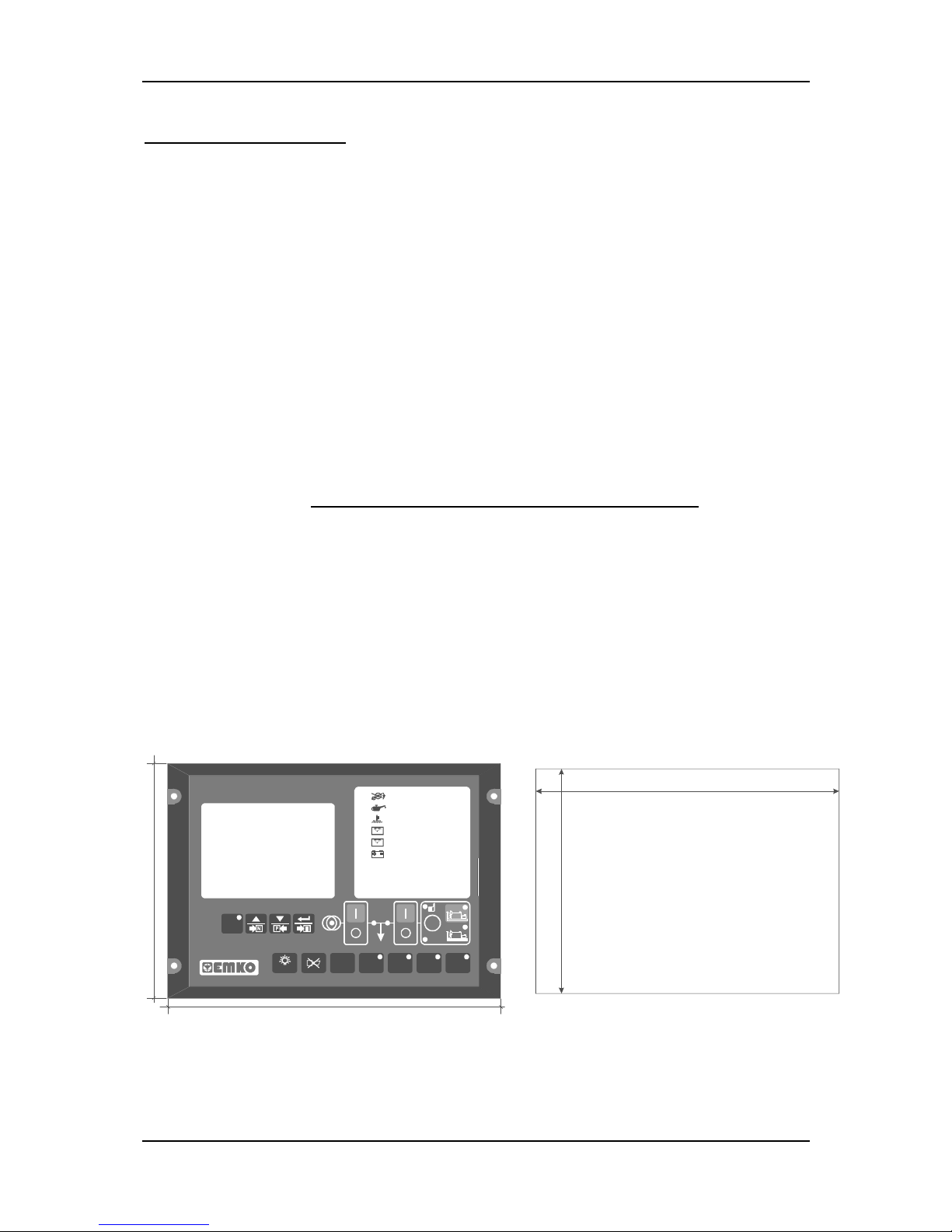
The unit is designed for panel mounting. Fixing is by four screw fixings. ( See Figure 2.1)
1. Insert the unit in the panel cut-out from the front.
2. Insert the fixings in the slotted at the corners of the unit and tighten the fixing screws
to secure the unit against the panel.
During the equipment is putted in hole on the metal panel while mechanical
installation some metal burrs can cause injury on hands, you must be careful.
1
4
4
m
m
204mm
186mm
138mm
V
HIGH TEMPERATURE
FAILED TO START
LOW OIL PRESSURE
SPEED FAILURE
VOLTAGE FAILURE
CHARGING FAIL
RPM
MAINS
MANUAL
TESTAUTOOFFRESET
TEST
PROG
EAOM - 210 FL
STOP
START
G
ENGINE
RUNNING
LOAD
Figure 2.1 Front view. Figure 2.2 Panel cut-out
Page 8
EAOM-210 FLJ.eng / ver 0.0
Pages 8 / 132
7
m
m
1
9
m
m
3
4
.
5
m
m
89.5mm
29mm
144mm
C
A
N
L
C
A
N
H
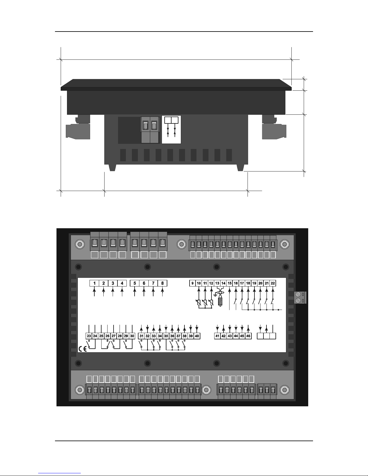
Figure 2.3 Side view.
2.3 Electrical Connections
1
5263748
9
3531 41
10
3632 42
11
3733 43 45
12
3834 44 46
RS-232
13
39 40
14231524162517261827192820
29 30
21 22
C
H
A
R
G
E
G
E
N
.
D
+
(
W
.
L
.
)
C
O
N
F
. I
N
P
U
T
3
- BATTERY
E
.
S
T
O
P
L
1
MAINS
L2
L3
N
L1
L2L3N
GENERATOR
C
O
M
M
O
N
L
E
V
E
L
S
E
N
D
E
R
T
E
M
P
.
S
E
N
D
E
R
O
I
L
P
R
E
S
.
S
E
N
D
E
R
MAGNETIC
PICKUP
(Max. 10kHz)
S
G
NGN
D
C
O
N
F
. I
N
P
U
T
4
C
O
N
F
. I
N
P
U
T
5
C
O
N
F
. I
N
P
U
T
6
5A @
250 V 5A @
250 V 5A @
250 V 5A @
250 V
MAINS OPEN
CONTACTOR
MAINS CLOSE
CONTACTOR
GEN. OPEN
CONTACTOR
GEN. CLOSE
CONTACTOR
MAXIMUM
300 V
(Ph - N)
MAXIMUM
300 V
(Ph - N)
LOW OIL PRES.
OR CONF. INPUT 1
+
B
A
T
T
E
R
Y
-
B
A
T
T
E
R
Y
C
O
N
F
.
O
U
T
-
4
C
O
N
F
.
O
U
T
-
3
C
O
N
F
.
O
U
T
-
2
+
B
A
T
T
E
R
Y
16A @
250 V
16A @
250 V
16A @
250 V
5A @
250 V 5A @
250 V 5A @
250 V
+
B
A
T
T
E
R
Y
S
O
L
E
N
O
I
D
S
T
A
R
T
BATTERY
VOLTAGE
8-32 V
ICOMIL2IL3IEA
LOAD
IL1
H
O
R
N
O
U
T
O
R
C
O
N
F
.
O
U
T
-
1
H
I
G
H
T
E
M
P
.
O
R
C
O
N
F
.
I
N
P
U
T
2
+BATTERY
*
*
IT CAN BE U SED
AS A DIGITAL INPUT
BY SELECTING
FROM THE PROG RAM
PARAMETERS
*
C
H
A
R
G
E
G
E
N
.
D
+
(
W
.
L
.
)
C
O
N
F
. I
N
P
U
T
3
- BATTERY
E
.
S
T
O
P
L
1
MAINS
L2
L3
N
L1
L2L3N
GENERATOR
L
E
V
E
L
S
E
N
D
E
R
T
E
M
P
.
S
E
N
D
E
R
O
I
L
P
R
E
S
.
S
E
N
D
E
R
MAGNETIC
PICKUP
(Max. 10kHz)
S
G
N
G
N
D
C
O
N
F
. I
N
P
U
T
6
5A @
250 V 5A @
250 V 5A @
250 V 5A @
250 V
MAINS OPEN
CONTACTOR
MAINS CLOSE
CONTACTOR
GEN. OPEN
CONTACTOR
GEN. CLOSE
CONTACTOR
MAXIMUM
300 V
(Ph - N)
MAXIMUM
300 V
(Ph - N)
LOW OIL PRES .
OR CONF. INPUT 4
+
B
A
T
T
E
R
Y
-
B
A
T
T
E
R
Y
C
O
N
F
.
O
U
T
-
4
C
O
N
F
.
O
U
T
-
3
C
O
N
F
.
O
U
T
-
2
+
B
A
T
T
E
R
Y
16A @
250 V
16A @
250 V
16A @
250 V
5A @
250 V 5A @
250 V 5A @
250 V
+
B
A
T
T
E
R
Y
S
O
L
E
N
O
I
D
S
T
A
R
T
BATTERY
VOLTAGE
8-32 V
ICOMIL2IL3IEA
LOAD
IL1
H
O
R
N
O
U
T
O
R
C
O
N
F
.
O
U
T
-
1
H
I
G
H
T
E
M
P
.
O
R
C
O
N
F
.
I
N
P
U
T
5
+BATTERY
*
*
IT CAN BE U SED
AS A DIGITAL INPUT
BY SELECTING
FROM THE PROG RAM
PARAMETERS
*
- BATTERY
NC
C
O
N
F
. I
N
P
U
T
2
C
O
N
F
. I
N
P
U
T
1
RS 232
COMMUNICATION
G
N
DRXTX
Figure 2.4 Rear view.
Page 9

EAOM-210 FLJ.eng / ver 0.0
Pages 9 / 132
Only qualified personnel and technicians trained specially should work on this
equipment. This equipment contains internal circuits with voltage dangerous
to human life. There is severe danger for human life in the case of unauthorized
intervention.
Keep the power off until all of the wiring is completed so that electric shock and
trouble with the unit can be prevented.
Page 10
EAOM-210 FLJ.eng / ver 0.0
Pages 10 / 132
1 52 63 25
M
a
g
n
e
t
i
c
P
i
c
k
u
p
29 74 26
1
4
1
3
30 8
L
1
G
E
N
E
R
A
T
O
R
Maximum ~300VMaximum ~300V
MAINS
L2L3N
40393231 33 34
M
M
a
i
n
s
C
o
n
t
a
c
t
o
r
C
l
o
s
e
R
e
l
a
y
O
u
t
.
L
O
A
D
G
G
e
n
.
C
o
n
t
a
c
t
o
r
C
l
o
s
e
R
e
l
a
y
O
u
t
.
L1L2L3
N
E
l
e
c
t
r
i
c
a
l
i
n
t
e
r
l
o
c
k
M
e
c
h
a
n
i
c
a
l
i
n
t
e
r
l
o
c
k
4
3
4
4
4
5
4
6
*
IT CAN BE USED
AS A DIGITAL INPUT
BY SELECTING
FROM THE PROGRAM
PARAMETERS
2
2
1
2
B
A
T
T
E
R
Y
-
2
1
1
1
2
0
1
0
1
9
1
8
1
7
1
6
1
5
B
A
T
T
E
R
Y
+
*
*
B
A
T
T
E
R
Y
-
G
e
n
.
C
o
n
t
a
c
t
o
r
O
p
e
n
R
e
l
a
y
O
u
t
.
M
a
i
n
s
C
o
n
t
a
c
t
o
r
O
p
e
n
R
e
l
a
y
O
u
t
.
BATTERY -
BATTERY +
Configurable Output-2
Configurable Output-3
Configurable Output-4
BATTERY +
Horn or Configurable Output-1
Start
Solenoid
BATTERY +
E. Stop
Configurable Input-1
Configurable Input-2
Configurable Input-3
Low Oil Pres.
Or Configurable Input-4
High Temp.
Or Configurable Input-5
Configurable Input-6
GND
SGN
D+(W.L.)
Charge Gen.
Oil Pressure
Temperature
Level
FUSE-7
FUSE-8
FUSE-9
16A
16A
16A
FUSE-6
FUSE-5
FUSE-4
FUSE-11
FUSE-10
FUSE-3
FUSE-2
FUSE-1
5A
5A
5A
5A
4
1
4
2
2
1
Expansion I/O Module and / or
J1939 ECUs
KLM4
CANH
CANL
COM1
RS-232
RX
TX
GND
3
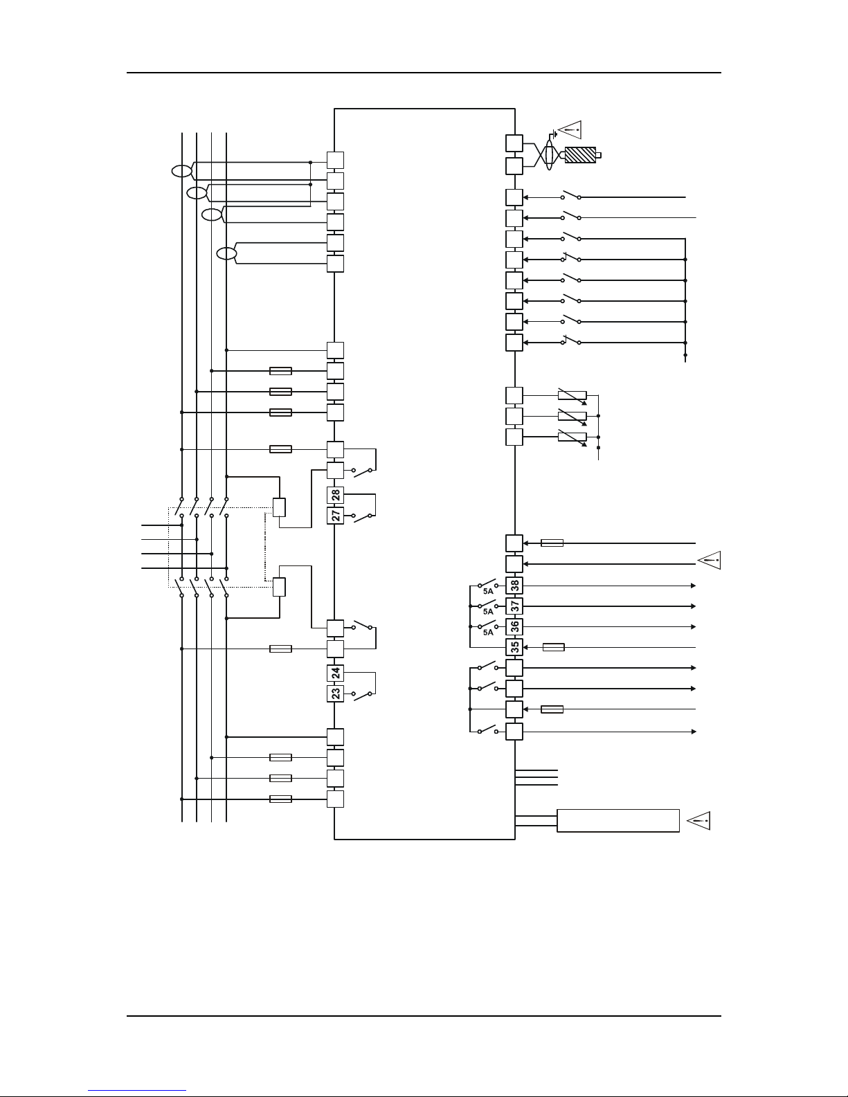
Figure 2.5 EAOM-210 FLJ three phase connections schematic.
FUSE-1, FUSE-2, FUSE-3, FUSE-4, FUSE-5, FUSE-6, FUSE-7 1 A. T
FUSE-8 should meet the current required by configurable output-2, 3, 4 – 15 A.T max
FUSE-9 should meet the current required by solenoids (Max. 16 A. T)
FUSE-10, FUSE-11 Max. 5A. T
Page 11

EAOM-210 FLJ.eng / ver 0.0
Pages 11 / 132
1-
2-
Connect the unit as shown in the appropriate diagram. Be sure to connect
the battery supply the right way round and battery negative should be
grounded. The connectors can be unplugged from the rear of the unit to
facilitate connection.
Screened cable must be used for connecting the Magnetic Pickup,
ensuring that the screen is grounded at one end ONLY.
3 The CAN interface requires that a 120 Ohms terminator is fitted to each
end of the communications link. This termination resistor is fitted internally
into the unit. So it is not required externally.
-
Page 12

EAOM-210 FLJ.eng / ver 0.0
Pages 12 / 132
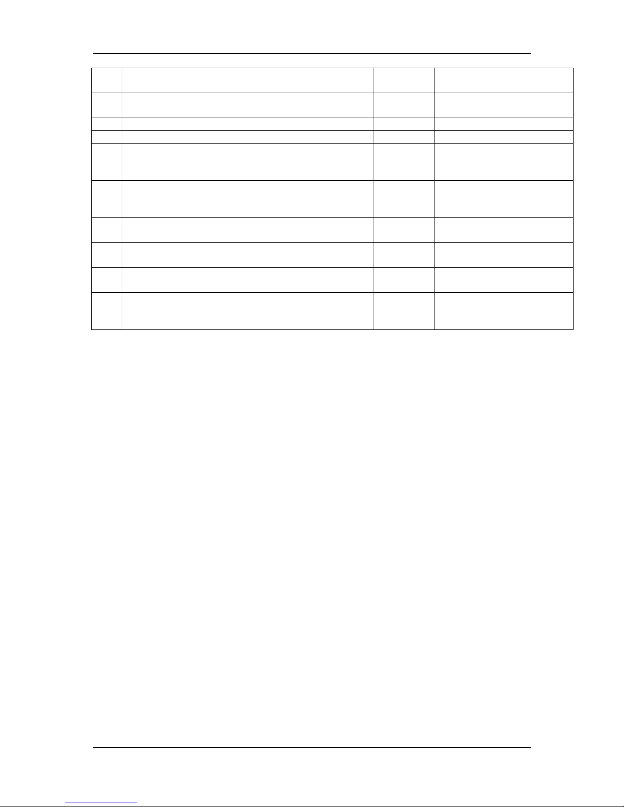
Table 2.1 shows the connections and recommended cable sizes. Table 2.2 describes
the functions of the connections.
Table 2.1 Unit wiring
Pin Description Cable Size
(mm²)
Notes
1 Mains voltage input (L1) 2,5
2 Mains voltage input (L2) 2,5 3 phase applications only.
3 Mains voltage input (L3) 2,5 3 phase applications only.
4 Mains voltage neutral 2,5
5 Alternator voltage input (L1) 2,5
6 Alternator voltage input (L2) 2,5 3 phase applications only.
7 Alternator voltage input (L3) 2,5 3 phase applications only.
8 Alternator voltage neutral 2,5
9 Not connected
10 Fuel level sender 1
Connect to fuel level
sender
11 Coolant temperature sender 1
Connect to Coolant
temperature sender
12 Low oil pressure sender 1
Connect to Low oil pressure
sender
13
14
Input from magnetic pick-up 1
Connect to magnetic pick-
up device
15 Input from charge generator 1 NC to “0” volt.
16 Configurable input-6 1 Switch to “BATTERY +”.
17 High temperature or configurable input-5 1 Switch to “0” volt.
18 Low oil pressure or configurable input-4 1 Switch to “0” volt.
19 Configurable input-3 1 Switch to “0” volt.
20 Configurable input-2 1 Switch to “0” volt.
21 Configurable input-1 1 Switch to “0” volt.
22 Input from emergency stop 1 NC to “0” volt. When the
switch is opened, the
engine is stopped.
23 Mains Contactor Open Relay Output 2,5
24 Mains Contactor Open Relay Output 2,5
25 Mains Contactor Close Relay Output 2,5
26 Mains Contactor Close Relay Output 2,5
27 Gen. Contactor Open Relay Output 2,5
28 Gen. Contactor Open Relay Output 2,5
29 Gen. Contactor Close Relay Output 2,5
30 Gen. Contactor Close Relay Output 2,5
31 Output to fuel / stop solenoid 2,5 16 A. Max.
DC supply from Pin 32
32 +Battery supply input 2,5 Supplies to Pin 31,33,34
33 Output to start 2,5 16 A. Max.
DC supply from Pin 32
34 Horn or configurable relay output-1 2,5 16 A. Max.
DC supply from Pin 32
35 +Battery supply input 2,5 Supplies to Pin 36,37,38
36 Configurable relay output-2 2,5 5 A. Max.
DC supply from Pin 35
Page 13
EAOM-210 FLJ.eng / ver 0.0
Pages 13 / 132
37 Configurable relay output-3 2,5 5 A. Max.
DC supply from Pin 35
38 Configurable relay output-4 2,5 5 A. Max.
DC supply from Pin 35
39 - Battery supply to EAOM-210 FLJ 2,5 Supplies to unit
40 + Battery supply to EAOM-210 FLJ 2,5 Supplies to unit
41 CT Secondary for Earth current 2,5 Connect to secondary of
Earth current monitoring
CT
42 CT Secondary for Earth current 2,5 Connect to secondary of
Earth current monitoring
CT
43 CT Secondary for load L3 2,5 Connect to secondary of
load L3 monitoring CT
44 CT Secondary for load L2 2,5 Connect to secondary of
load L2 monitoring CT
45 CT Secondary for load L1 2,5 Connect to secondary of
load L1 monitoring CT
46 Common for load L1, L2, L3 2,5 Connect to secondary of
load common monitoring
CT
Page 14

EAOM-210 FLJ.eng / ver 0.0
Pages 14 / 132
Table 2.2 Unit wiring description
Pin Function
1 L1
2 L2
3 L3
Mains voltage inputs. Used to detect failure for controlling automatic transfer of load
to alternator. Pins 2 and 3 not used on single phase applications.
4 Mains voltage neutral
5 L1
6 L2
7 L3
Alternator voltage inputs. Unit can be programmed to use frequency of alternator
output to detect when engine has started. Pins 6 and 7 not used on single phase
applications.
8 Alternator voltage neutral
9 Not connected
10 Fuel level sender
11 Coolant temperature sender
12 Low oil pressure sender
13 Magnetic input +ve. An AC signal from the magnetic pick-up +ve for speed sensing.
14 Magnetic input –ve. An AC signal from the magnetic pick-up -ve for speed sensing.
15 Input from charge generator. Can be used to detect when engine has started.
16
Configurable input-6. This is a negative switched configurable input, see Digital
Configurable Input-6 Page Section for options available. It is possible to configure input to
be a normally closed signal or a normally open signal.
17
High Temperature or Configurable input-5. This is a negative switched. If Configurable
input-5 is not selected as High Temperature, It is possible to configure input to be a
normally closed signal or a normally open signal. See Digital Configurable Input-5 Page
Section for options available.
18
Low Oil Pressure or Configurable input-4. Normally closed contact. Switch to 0V. If
Configurable input-4 is not selected as Low Oil Pressure, It is possible to configure input to
be a normally closed signal or a normally open signal. See Digital Configurable Input-4 Page
Section for options available.
19
Configurable input-3. This is a negative switched configurable input, see Digital
Configurable Input-3 Page Section for options available. It is possible to configure input to
be a normally closed signal or a normally open signal.
20
Configurable input-2. This is a negative switched configurable input, see Digital
Configurable Input-2 Page Section for options available. It is possible to configure input to
be a normally closed signal or a normally open signal.
21
Configurable input-1. This is a negative switched configurable input, see Digital
Configurable Input-1 Page Section for options available. It is possible to configure input to
be a normally closed signal or a normally open signal.
22
Input from emergency stop switch. Normally closed contact. Switch to 0V. when the switch
is opened, the engine is stopped.
23
Mains Contactor Open Relay Output. See Breakers Page Section for options available. Volts
free contacts to 24.
24
Mains Contactor Open Relay Output. See Breakers Page Section for options available. Volts
free contacts to 24.
25
Mains Contactor Close Relay Output. See Breakers Page Section for options available. Volts
free contacts to 26.
26
Mains Contactor Close Relay Output. See Breakers Page Section for options available. Volts
free contacts to 25.
27
Gen. Contactor Open Relay Output. See Breakers Page Section for options available. Volts
free contacts to 28.
28
Gen. Contactor Open Relay Output. See Breakers Page Section for options available. Volts
free contacts to 27.
Page 15

EAOM-210 FLJ.eng / ver 0.0
Pages 15 / 132
29
Gen. Contactor Close Relay Output. See Breakers Page Section for options available. Volts
free contacts to 30.
30
Gen. Contactor Close Relay Output. See Breakers Page Section for options available. Volts
free contacts to 29.
31
Output to fuel / stop relay. DC supply from Pin 32. Controls fuel to engine or controls
engine stopping.
32 +Battery supply input. Supplies to Pin 31,33,34
33 Output to start relay. DC supply from Pin 32. Controls starter motor.
34
Horn or configurable relay output-1. DC supply from Pin 32. See Configurable Output-1 Page
Section for options available.
35 +Battery supply input. Supplies to Pin 36,37,38
36
Configurable relay output-2. DC supply from Pin 35. See Configurable Output-2 Page Section
for options available.
37
Configurable relay output-3. DC supply from Pin 35. See Configurable Output-3 Page Section
for options available.
38
Configurable relay output-4. DC supply from Pin 35. See Configurable Output-4 Page Section
for options available.
39 - Battery input supplies EAOM-210 FLJ
40 + Battery input supplies EAOM-210 FLJ
41 CT Secondary for Earth current (IEA).
42 CT Secondary for Earth current (IEA).
43 CT Secondary for load L3.
44 CT Secondary for load L2.
45 CT Secondary for load L1.
46 CT Secondary for load common.
Page 16

EAOM-210 FLJ.eng / ver 0.0
Pages 16 / 132
Electronic Engines (ECUs) and EAOM-210FLJ unit
Volvo EMS2:
Fitted to Volvo Penta engine types : TAD734, TAD940, TAD941, TAD1640, TAD1641,
TAD1642
EAOM-210FLJ
Terminal
Volvo EMS2
Connector
Terminal
Notes
Conf. Output-3 6 Please select the relevant engine and
configurable output 3 to be “ECU
STOP”
Conf. Output-2 5 Please select the relevant engine and
configurable output 2 to be “ECU
POWER”
3 DC Supply negative
4 DC Supply positive
CAN H 1 (High)
J1939 + Use only screened 120Ω
impedance cable approved specifically
for use in CanBus applications.
CAN L 2 (Low)
J1939 – Use only screened 120Ω
impedance cable approved specifically
for use in CanBus applications.
Volvo EDC4:
Fitted to Volvo Penta engine types : TD520, TAD520 (optional), TD720, TAD720 (optional),
TAD721, TAD722
EAOM-210FLJ
Terminal
Volvo EDC4
Connector
Terminal
Notes
Start (crank) Output Connects directly to engine starter
solenoid.
Fuel Output Use to control a 30A
external slave relay to
supply DC battery power
to pin 14. Fuse at 16
amps.
1 Connects directly to battery negative
CAN H 12 (High)
J1939 + Use only screened 120Ω
impedance cable approved specifically
for use in CanBus applications.
CAN L 13 (Low)
J1939 – Use only screened 120Ω
impedance cable approved specifically
for use in CanBus applications.
Page 17
EAOM-210 FLJ.eng / ver 0.0
Pages 17 / 132
PERKINS:
Perkins engines fitted with the ADEM3 / ADEM4: 2306, 2506, 1106, 2806
EAOM-210FLJ
Terminal
PERKINS
Customer Interface
Connector
Notes
Fuel Output 1, 10, 15, 33, 34 Powers up ECU and enables the
injectors.
Start (crank) Output Connects directly to engine starter
solenoid.
CAN H 31 (High)
J1939 + Use only screened 120Ω
impedance cable approved specifically
for use in CanBus applications.
CAN L 32 (Low)
J1939 – Use only screened 120Ω
impedance cable approved specifically
for use in CanBus applications.
Page 18
EAOM-210 FLJ.eng / ver 0.0
Pages 18 / 132
Section 3 Definition Of Front Panel And Programming
3.1 Front Panel Description
OFF
TEST
AUTO
TEST
MANUAL
RESET
PROG
START
MAINS
LOAD
STOP
N P
2
3 4
5
6
7
8
9
101112
17
18
20
19
21
22
2928272624
13
31
30
1
14 15 16
23
25
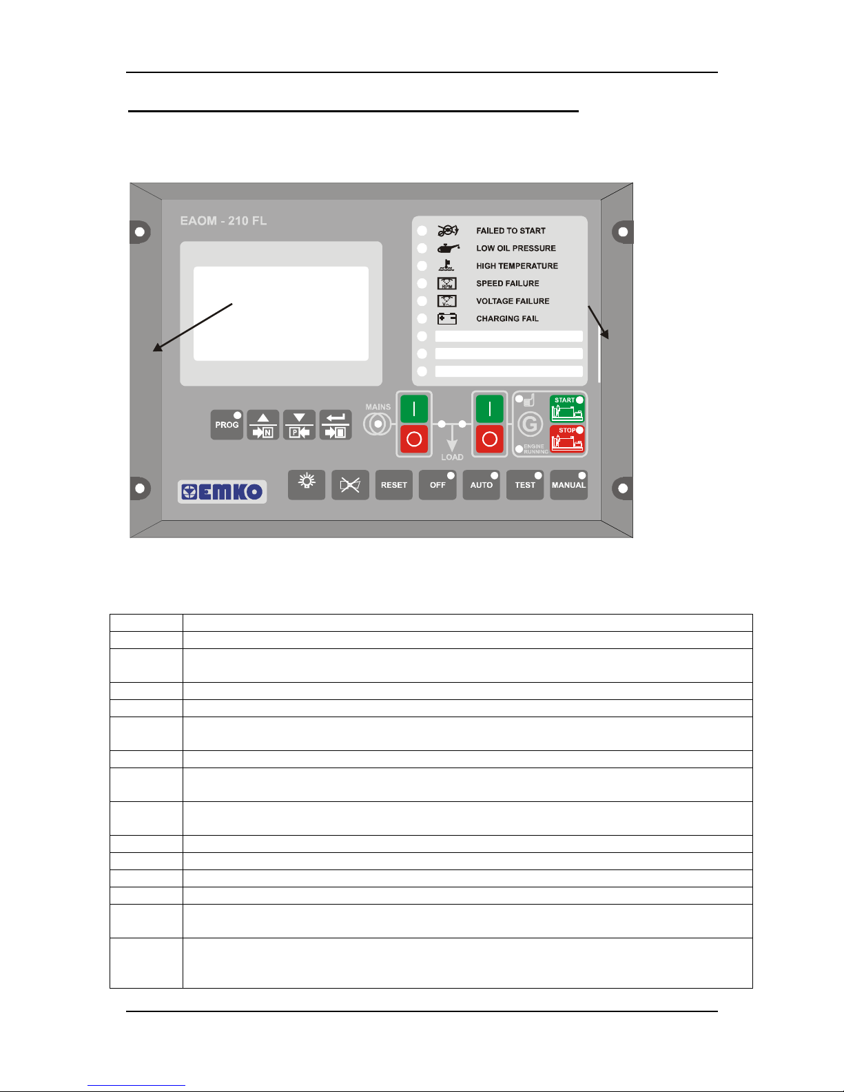
Number Comment:
1 The red LED illuminates only when the EAOM-210 FLJ in the Programming Mode.
2
The green LED indicates that Mains voltage and frequency is within limits and is ready
to take over the load.
3 The LED shows that the load is connected to the mains. It’s colour is green.
4 The LED shows that the load is supplied from the generator. It’s colour is green.
5
The green LED indicates that Generator Voltage is within limits and is ready to take
over the load.
6 The green LED indicates that the engine has started and is running.
7
In the MAN, AUTO and TEST modes, the green LED indicates that the engine is starting
up or is running.
8
In the MAN, AUTO and TEST modes, the red LED indicates that the engine has stopping
or stopped.
9 This red LED shows that the unit is in the OFF mode.
10 This red LED shows that the unit is in the AUTO mode.
11 This red LED shows that the unit is in the TEST mode.
12 This red LED shows that the unit is in the MANUAL mode.
13
When this button is pressed, the unit goes into its PROGRAMMING Mode and LED (1)
illuminates.
14
This button is used for showing next working screen in normal operation. In
Programming mode, it operates as an page changing function or increment function
(increase value).
Page 19

EAOM-210 FLJ.eng / ver 0.0
Pages 19 / 132
Number Comment:
15
This button is used for showing previous working screen in normal operation. In
Programming mode, it operates as an page changing function or decrement function
(decrease value).
16
This button is used for rotating between Event Log screens in normal operation, and
between programming parameters in programming mode.
17 This button closes the mains contactor, only operative when manual mode is selected.
18 This button opens the mains contactor, only operative when manual mode is selected.
19
This button closes the alternator contactor, only operative when manual mode is
selected.
20
This button opens the alternator contactor, only operative when manual mode is
selected.
21 The START button is used for starting the engine when the unit is in the Manual Mode.
22 The STOP button is used for stopping the engine when the unit is in the Manual Mode.
23 The LAMP TEST button illuminates all LED indicators.
24 This button will silence the alarm horn after a failure has been detected.
25 This button will reset the controller after a failure has been detected.
26 The OFF button is used for changing operating mode of the unit to the OFF Mode.
27 The AUTO button is used for changing operating mode of the unit to the AUTO Mode.
28 The TEST button is used for changing operating mode of the unit to the TEST Mode.
29 The MAN button is used for changing operating mode of the unit to the MANUAL Mode.
30
128x64 Dot matrix LCD Display. This is used for displaying the electrical measurements
during normal operation (features explained in section 5.1.1.), and editing/inspecting
programming parameters in program mode.
31 Failure Indicators. Detailed information available in section 5.1.2.
Page 20
EAOM-210 FLJ.eng / ver 0.0
Pages 20 / 132
3.2 Programming Procedure
Many of the unit functions can be set by programming. Programming can be
carried out only while the unit is in OFF mode. Press the OFF (26) button. If the engine
is running, it will stop and the LED (9) lights on.
The parameters have been divided into groups according to their functions. Every group
has a title and firstly user must determine the title (page) for accessing to the parameters.
Refer to the parameters section for detailed information about parameters.
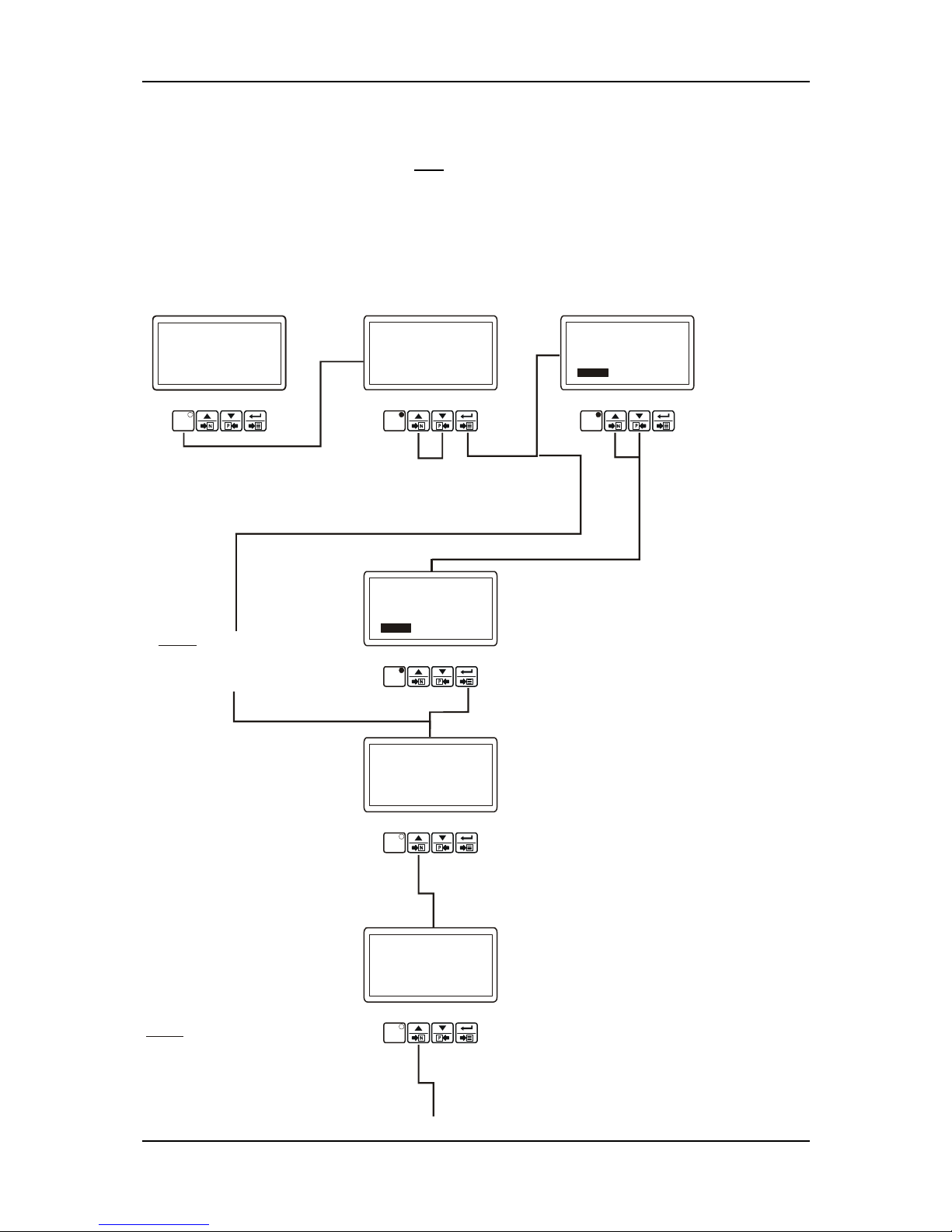
3.3 Accessing to the Operator Parameters
OPERATOR SECTION
PASSWORD
0
PROG
Operation Screen
Note1:
If Enter button is
pressed and the operator
password is zero, Password
screen is ignored.
OPERATOR PASSWORD
When the prog button is
pressed, password is
asked for accessing to
parameters.
User can access to operator parameters by
entering operator or technician password.
This selection is done with increment and
decrement buttons.
Enter
password with
increment and
decrement
buttons.
Press the Enter button to
confirm password. If the
password is incorrect, the
unit will drop out of
program mode.
Note2:
When Password
message is shown, parameters
can be seen by pressing Enter
button without entering operator
password. But user can not
change the parameters.
Operator and technician
can access to this page.
MAINS LEVELS Page
PROG
OPERATOR SECTION
PROG
OPERATOR SECTION
PASSWORD
161
PROG
OPERATOR SECTION
MAINS LEVELS PAGE
PROG
OPERATOR SECTION
GEN.VOLT.LEVELS PAGE
PROG
Operator or technician
can access
to the following page by pressing
increment button
Operator and technician
can access to this page.
Operator or technician can access
to the following page by pressing
increment button
GENERATOR VOLTAGE
LEVELS Page
MAINS & LOAD
L12: 380Vac I1: 126A
Fq:50.0Hz
AUTO
L23: 380Vac I2: 126A
L31: 380Vac I3: 126A
IT: 378A
IEA: 63A
CRANKNG ATTEMP
OVER SPEED PREALARM!
Page 21
EAOM-210 FLJ.eng / ver 0.0
Pages 21 / 132
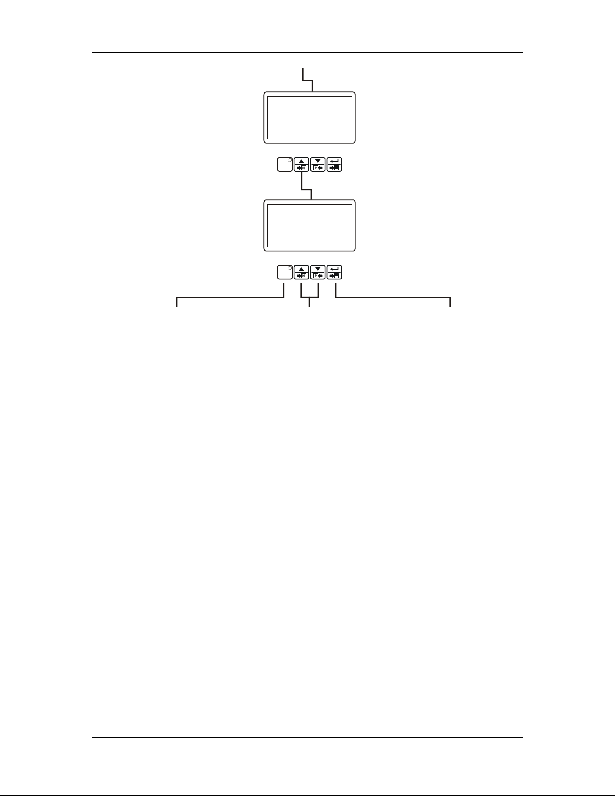
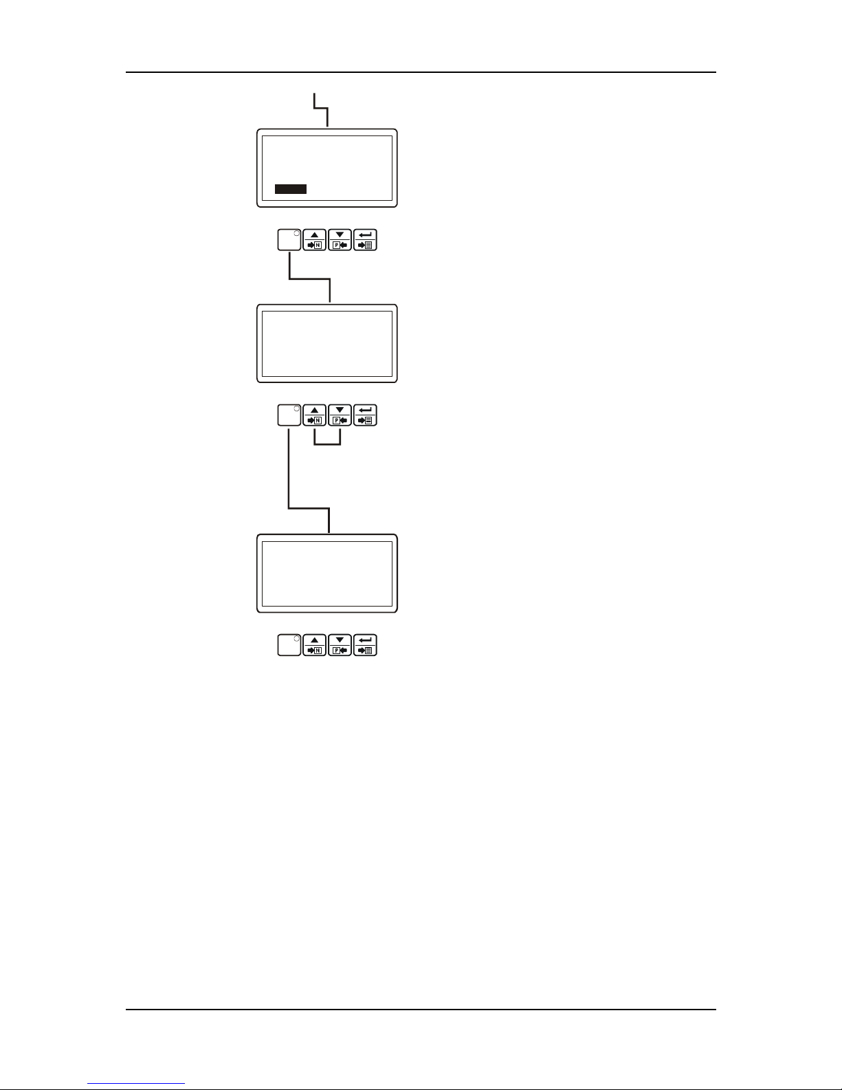
Press prog button to exit
from Program Mode and
turn to operation screen.
Operator and technician can access to this
page
Operator or technician can access to the
following page by pressing increment button
Continue to press increment and
decrement buttons to change the
page.
GENERATOR FEQUENCY
LEVELS Page
Operator and technician can access to this
page
GENERATOR CURRENT/POWER
LEVELS Page
By pressing ENTER button,
user can access to all
parameters in related page.
OPERATOR SECTION
GEN.FREQ.LEVELS PAGE
PROG
Operator or technician can access to the
former page by pressing decrement button
OPERATOR SECTION
GEN.CUR/POW.LVL PAGE
PROG
Operator or technician can access to the
former page by pressing decrement button
If the sensing options generator
frequency parameter(Gen1) in
Miscellaneous page(Gen) is disable,
this page is ignored.
Page 22
EAOM-210 FLJ.eng / ver 0.0
Pages 22 / 132
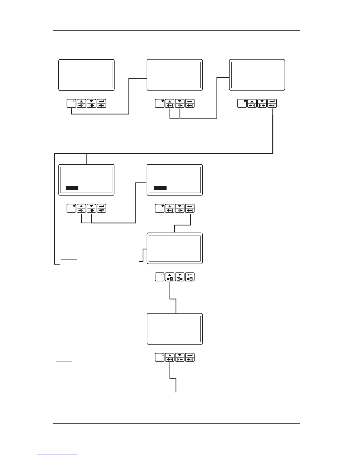
3.3.1 Changing and Saving Operator Parameter Values
Example-1 : To change Mains Under Voltage parameter in ”MAINS LEVELS PAGE”, user must
access to “MAINS LEVELS PAGE” page firstly.
OPERATOR SECTION
PASSWORD
0
PROG
Operation Screen
OPERATOR PASSWORD
When the prog button is
pressed, password is
asked for accessing to
parameters.
User can access to operator parameters by
entering operator or technician password.
This selection is done with increment and
decrement buttons.
Enter
password with
increment and
decrement
buttons.
Press the Enter button to
confirm password. If the
password is incorrect, the
unit will drop out of
program mode.
Operator and technician
can access to this page.
MAINS LEVELS Page
PROG
OPERATOR SECTION
PROG
OPERATOR SECTION
PASSWORD
161
PROG
OPERATOR SECTION
MAINS LEVELS PAGE
PROG
OPERATOR SECTION
MAINS LEVELS PAGE
MAINS UNDER VOLTAGE
Vac 320
PROG
Press Enter button to access
to first parameter in Mains
Levels page.
Mains Under Voltage parameter
Parameter can be changed with
increment and decrement buttons
OPERATOR SECTION
MAINS LEVELS PAGE
MAINS UNDER VOLTAGE
Vac 322
PROG
Press Enter button to confirm the
changed value and access to the
following parameter.
Note1:
If Enter button is
pressed and the operator
password is zero, Password
screen is ignored.
MAINS & LOAD
L12: 380Vac I1: 126A
Fq:50.0Hz
AUTO
L23: 380Vac I2: 126A
L31: 380Vac I3: 126A
IT: 378A
IEA: 63A
CRANKNG ATTEMP
OVER SPEED PREALARM!
Page 23
EAOM-210 FLJ.eng / ver 0.0
Pages 23 / 132
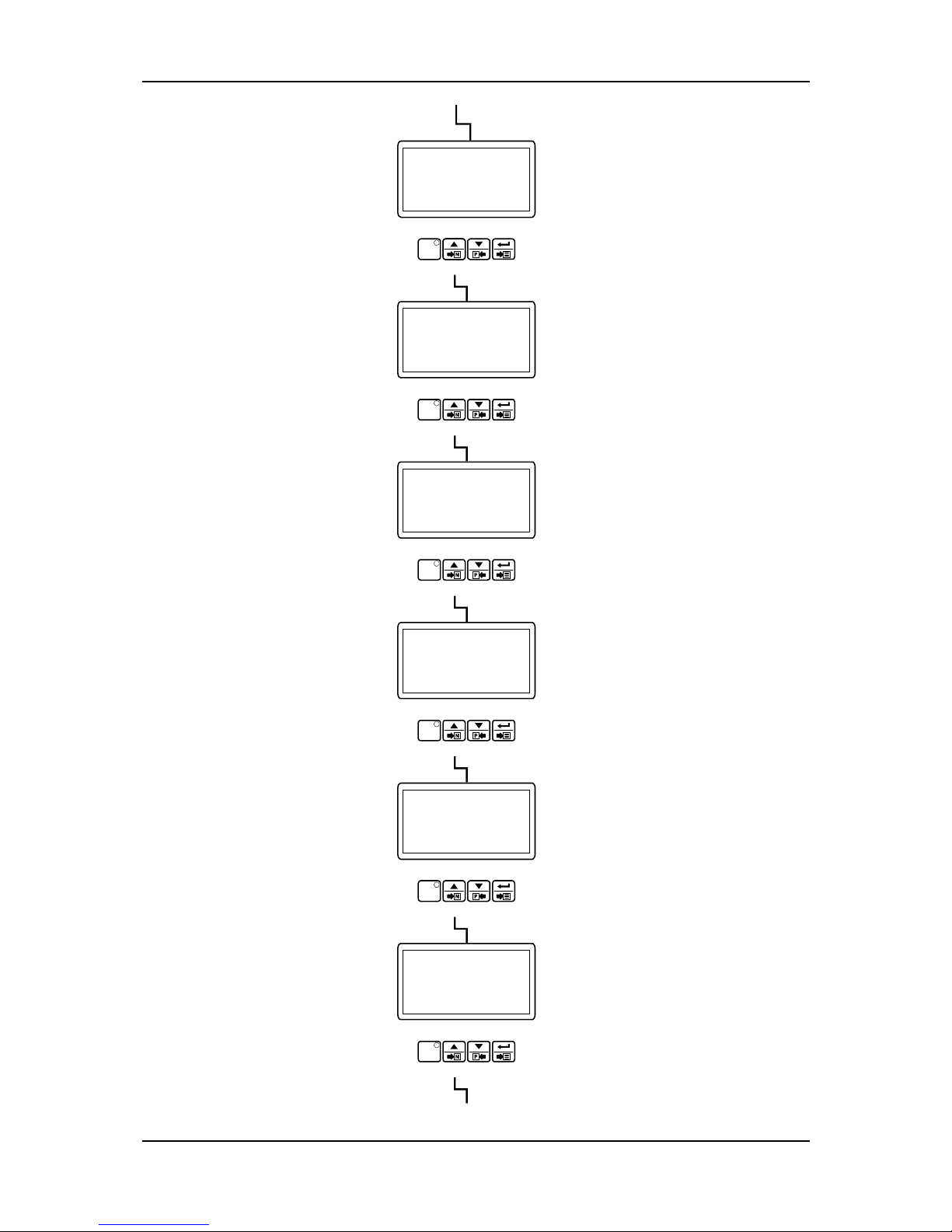
OPERATOR SECTION
MAINS LEVELS PAGE
MAINS UNDER V.RET.
Vac 340
PROG
Mains Under Voltage Return
parameter
MAINS LEVELS Page
When Prog button is pressed,
related page can be accessed.
OPERATOR SECTION
MAINS LEVELS PAGE
PROG
If Prog button is pressed
again, operation screen is
shown.
Continue to press increment and decrement
buttons to change the page.
Operation Screen
PROG
MAINS & LOAD
L12: 380Vac I1: 126A
Fq:50.0Hz
AUTO
L23: 380Vac I2: 126A
L31: 380Vac I3: 126A
IT: 378A
IEA: 63A
CRANKNG ATTEMP
OVER SPEED PREALARM!
Page 24
EAOM-210 FLJ.eng / ver 0.0
Pages 24 / 132
3.4 Accessing to the Technician Parameters
TECHNICIAN SECTION
PROG
Operation Screen
When the prog button is
pressed, password is
asked for accessing to
parameters.
PROG
OPERATOR SECTION
PROG
TECHNICIAN PASSWORD
Press the Enter button to
confirm password. If the
password is incorrect, the
unit will drop out of
program mode.
TECHNICIAN SECTION
PASSWORD
162
PROG
User can access to technician parameters
by entering technician password. This
selection is done with increment and
decrement buttons.
Press the Enter button.
TECHNICIAN SECTION
PASSWORD
0
PROG
Enter password with
increment and
decrement buttons.
Note1:
If Enter button is pressed
and the technician password is
zero, Password screen is ignored.
TECHNICIAN SECTION
GEN.CUR/POW.ACT.PAGE
PROG
Note2:
When Password
message is shown, parameters
can be seen by pressing Enter
button without entering
password. But user can not
change the parameters.
technician
GENERATOR CURRENT/POWER
ACTIONS Page
TECHNICIAN SECTION
MISCELLANEOUS PAGE
PROG
Technician
can access to the
following page by pressing
increment button
Technician
can access to the
following page by pressing
increment button
MISCELLANEOUS Page
Operator can not
access to this page.
Operator can not
access to this page.
MAINS & LOAD
L12: 380Vac I1: 126A
Fq:50.0Hz
AUTO
L23: 380Vac I2: 126A
L31: 380Vac I3: 126A
IT: 378A
IEA: 63A
CRANKNG ATTEMP
OVER SPEED PREALARM!
Page 25
EAOM-210 FLJ.eng / ver 0.0
Pages 25 / 132
TECHNICIAN SECTION
ENGINE STAR.OPT PAGE
PROG
Technician
can access to the former
page by pressing decrement button.
Operator can not access to this page.
Technician can access to the following
page by pressing increment button.
ENGINE STARTING OPTIONS Page
ENGINE CRANK DISCONNECT Page
GENERATOR SPEED SETTINGS Page
If the sensing options pick up
parameter(Gen2) in Miscellaneous
page(Gen) is disable, this page is
ignored.
ENGINE PLANT BATTERY Page
ANALOGUE INPUTS Page
TECHNICIAN SECTION
ENG.CRANK DISCN.PAGE
PROG
Technician
can access to the former
page by pressing decrement button.
Operator can not access to this page.
Technician can access to the following
page by pressing increment button.
TECHNICIAN SECTION
GEN.SPED SETING PAGE
PROG
Technician
can access to the former
page by pressing decrement button.
Operator can not access to this page.
Technician can access to the following
page by pressing increment button.
TECHNICIAN SECTION
ENG.PLANT BATTR PAGE
PROG
Technician
can access to the former
page by pressing decrement button.
Operator can not access to this page.
Technician can access to the following
page by pressing increment button.
TECHNICIAN SECTION
ANALOGUE INPUTS PAGE
PROG
Technician
can access to the former
page by pressing decrement button.
Operator can not access to this page.
Technician can access to the following
page by pressing increment button.
TECHNICIAN SECTION
ANALG.SENDR LIN.PAGE
PROG
Technician
can access to the former
page by pressing decrement button.
Operator can not access to this page.
Technician can access to the following
page by pressing increment button.
ANALOGUE SENDER
LINEARISATIONS Page
Page 26
EAOM-210 FLJ.eng / ver 0.0
Pages 26 / 132
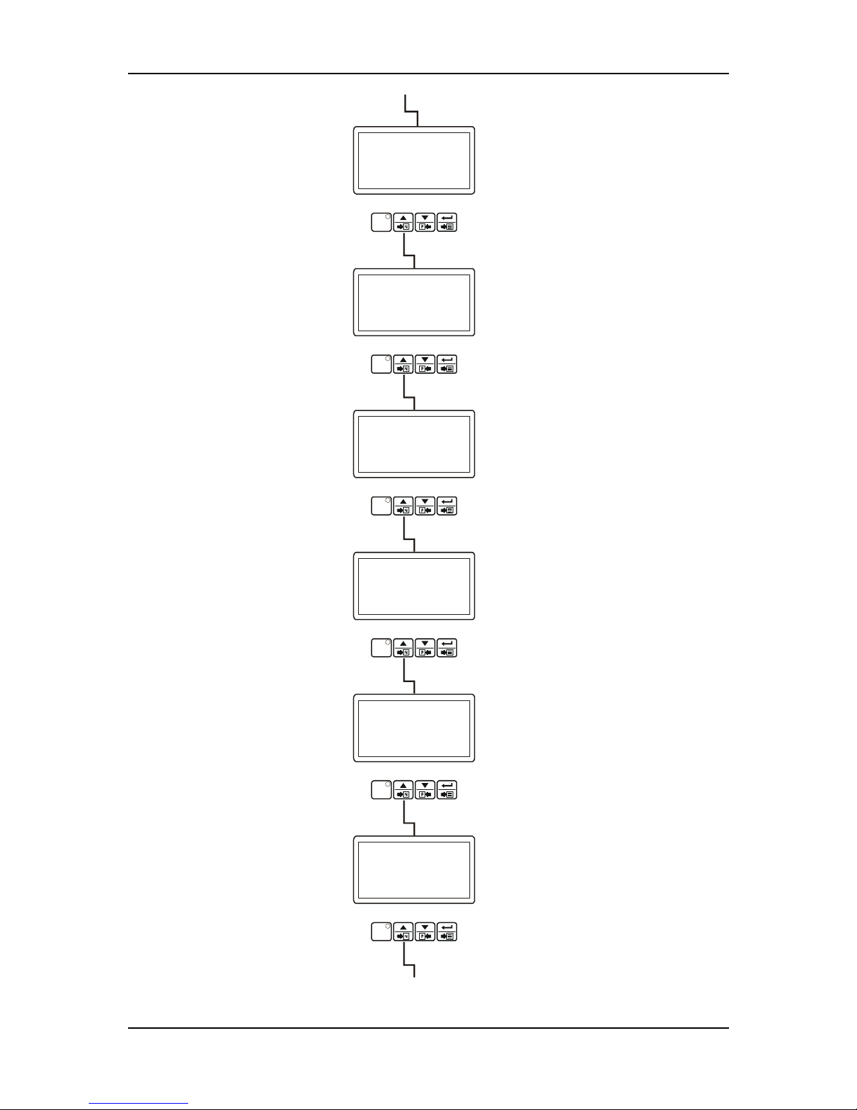
TECHNICIAN SECTION
CANBUS CONFIG. PAGE
PROG
Technician
can access to the former
page by pressing decrement button.
Operator can not access to this page.
Technician can access to the following
page by pressing increment button.
TECHNICIAN SECTION
CAN ERROR SET PAGE
PROG
Technician
can access to the former
page by pressing decrement button.
Operator can not access to this page.
Technician can access to the following
page by pressing increment button.
TECHNICIAN SECTION
PAGEDIG.CNF.INPUT-1
PROG
Technician
can access to the former
page by pressing decrement button.
Operator can not access to this page.
Technician can access to the following
page by pressing increment button.
TECHNICIAN SECTION
PAGEDIG.CNF.INPUT-2
PROG
Technician
can access to the former
page by pressing decrement button.
Operator can not access to this page.
Technician can access to the following
page by pressing increment button.
TECHNICIAN SECTION
PAGEDIG.CNF.INPUT-3
PROG
Technician
can access to the former
page by pressing decrement button.
Operator can not access to this page.
Technician can access to the following
page by pressing increment button.
TECHNICIAN SECTION
PAGEDIG.CNF.INPUT-4
PROG
Technician
can access to the former
page by pressing decrement button.
Operator can not access to this page.
Technician can access to the following
page by pressing increment button.
CANBUS & J1939 ERROR Page
DIGITAL CONFIGURABLE
INPUT-2 Page
DIGITAL CONFIGURABLE
INPUT-1 Page
DIGITAL CONFIGURABLE
INPUT-3 Page
DIGITAL CONFIGURABLE
INPUT-4 Page
CANBUS CONFIGURATION Page
Page 27
EAOM-210 FLJ.eng / ver 0.0
Pages 27 / 132
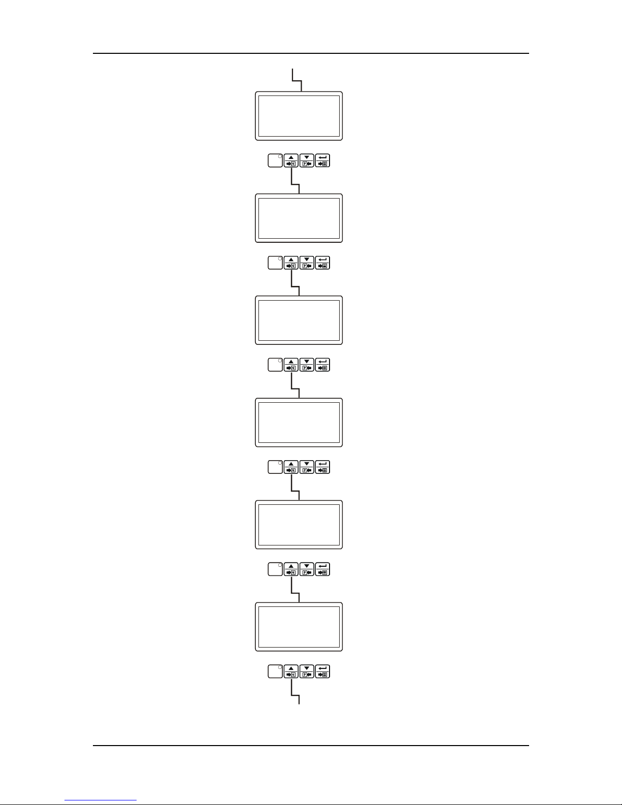
TECHNICIAN SECTION
DIG.CNF.INPUT-5 PAGE
PROG
Technician
can access to the former
page by pressing decrement button.
Operator can not access to this page.
Technician can access to the following
page by pressing increment button.
TECHNICIAN SECTION
PAGEDIG.CNF.INPUT-6
PROG
Technician
can access to the former
page by pressing decrement button.
Operator can not access to this page.
Technician can access to the following
page by pressing increment button.
TECHNICIAN SECTION
EXP PAGE.CNF.INPUT-1
PROG
Technician
can access to the former
page by pressing decrement button.
Operator can not access to this page.
Technician can access to the following
page by pressing increment button.
TECHNICIAN SECTION
EXP PAGE.CNF.INPUT-2
PROG
Technician
can access to the former
page by pressing decrement button.
Operator can not access to this page.
Technician can access to the following
page by pressing increment button.
TECHNICIAN SECTION
EXP PAGE.CNF.INPUT-3
PROG
Technician
can access to the former
page by pressing decrement button.
Operator can not access to this page.
Technician can access to the following
page by pressing increment button.
TECHNICIAN SECTION
EXP PAGE.CNF.INPUT-4
PROG
Technician
can access to the former
page by pressing decrement button.
Operator can not access to this page.
Technician can access to the following
page by pressing increment button.
EXPANSION CONFIGURABLE
INPUT-2 Page
EXPANSION CONFIGURABLE
INPUT-1 Page
EXPANSION CONFIGURABLE
INPUT-3 Page
EXPANSION CONFIGURABLE
INPUT-4 Page
DIGITAL CONFIGURABLE
INPUT-5 Page
If the Expansion Module Selection
parameter in CanBus Configuration
page is disable, this page is ignored.
If the Expansion Module Selection
parameter in CanBus Configuration
page is disable, this page is ignored.
If the Expansion Module Selection
parameter in CanBus Configuration
page is disable, this page is ignored.
If the Expansion Module Selection
parameter in CanBus Configuration
page is disable, this page is ignored.
DIGITAL CONFIGURABLE
INPUT-6 Page
Page 28
EAOM-210 FLJ.eng / ver 0.0
Pages 28 / 132
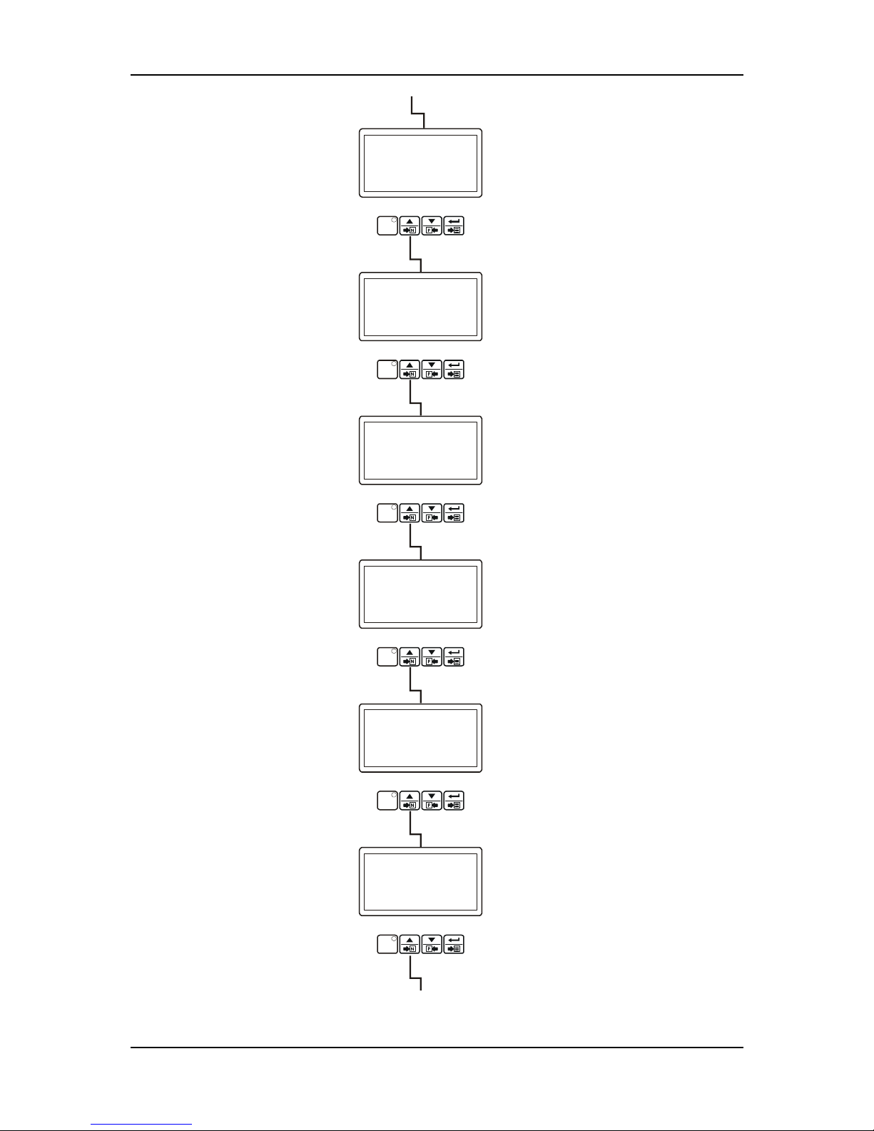
TECHNICIAN SECTION
EXP.CNF.INPUT-5 PAGE
PROG
Technician
can access to the former
page by pressing decrement button.
Operator can not access to this page.
Technician can access to the following
page by pressing increment button.
TECHNICIAN SECTION
EXP.CNF.IN PAGEPUT-6
PROG
Technician
can access to the former
page by pressing decrement button.
Operator can not access to this page.
Technician can access to the following
page by pressing increment button.
TECHNICIAN SECTION
EXP.CNF.IN PAGEPUT-7
PROG
Technician
can access to the former
page by pressing decrement button.
Operator can not access to this page.
Technician can access to the following
page by pressing increment button.
TECHNICIAN SECTION
PAGEEXP.CNF.INPUT-8
PROG
Technician
can access to the former
page by pressing decrement button.
Operator can not access to this page.
Technician can access to the following
page by pressing increment button.
TECHNICIAN SECTION
CONFIG.OUTPUT-1 PAGE
PROG
Technician
can access to the former
page by pressing decrement button.
Operator can not access to this page.
Technician can access to the following
page by pressing increment button.
TECHNICIAN SECTION
CONFIG.OUTPUT-2 PAGE
PROG
Technician
can access to the former
page by pressing decrement button.
Operator can not access to this page.
Technician can access to the following
page by pressing increment button.
EXPANSION CONFIGURABLE
INPUT-5 Page
If the Expansion Module Selection
parameter in CanBus Configuration
page is disable, this page is ignored.
CONFIGURABLE OUTPUT-1 Page
EXPANSION CONFIGURABLE
INPUT-6 Page
EXPANSION CONFIGURABLE
INPUT-7 Page
If the Expansion Module Selection
parameter in CanBus Configuration
page is disable, this page is ignored.
If the Expansion Module Selection
parameter in CanBus Configuration
page is disable, this page is ignored.
CONFIGURABLE OUTPUT-2 Page
EXPANSION CONFIGURABLE
INPUT-8 Page
If the Expansion Module Selection
parameter in CanBus Configuration
page is disable, this page is ignored.
Page 29
EAOM-210 FLJ.eng / ver 0.0
Pages 29 / 132
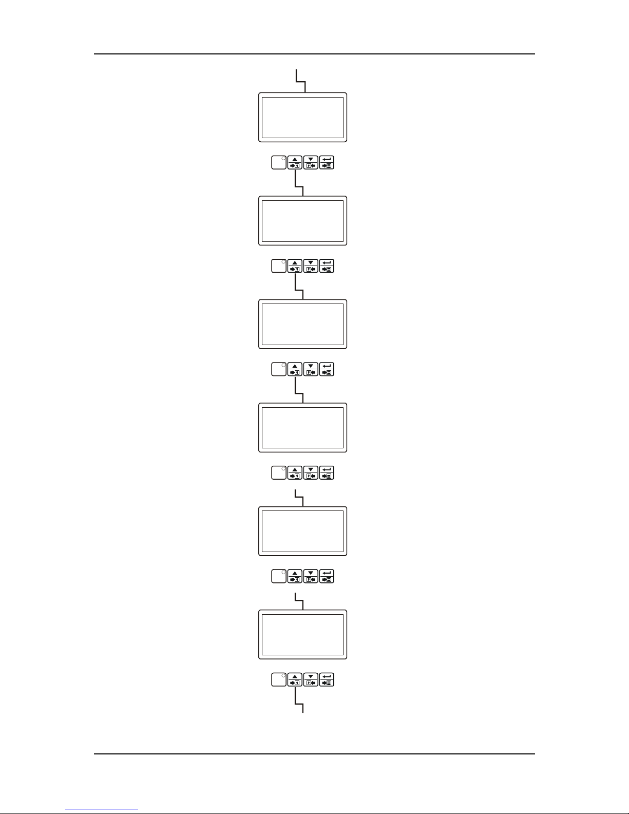
TECHNICIAN SECTION
CONFIG.OUTPUT-3 PAGE
PROG
Technician
can access to the former
page by pressing decrement button.
Operator can not access to this page.
Technician can access to the following
page by pressing increment button.
TECHNICIAN SECTION
PAGECONFIG.OUTPUT-4
PROG
Technician
can access to the former
page by pressing decrement button.
Operator can not access to this page.
Technician can access to the following
page by pressing increment button.
TECHNICIAN SECTION
EXP.CONFG.OUT PAGE
-1
PROG
Technician
can access to the former
page by pressing decrement button.
Operator can not access to this page.
Technician can access to the following
page by pressing increment button.
TECHNICIAN SECTION
EXP.CONFG.OUT-2 PAGE
PROG
Technician
can access to the former
page by pressing decrement button.
Operator can not access to this page.
Technician can access to the following
page by pressing increment button.
TECHNICIAN SECTION
EXP.CONFG.OUT-3 PAGE
PROG
Technician
can access to the former
page by pressing decrement button.
Operator can not access to this page.
Technician can access to the following
page by pressing increment button.
TECHNICIAN SECTION
EXP.CONFG.OUT-4 PAGE
PROG
Technician
can access to the former
page by pressing decrement button.
Operator can not access to this page.
Technician can access to the following
page by pressing increment button.
EXPANSION CONFIGURABLE
OUTPUT-4 Page
If the Expansion Module Selection
parameter in CanBus Configuration
page is disable, this page is ignored.
CONFIGURABLE OUTPUT-3 Page
EXPANSION CONFIGURABLE
OUTPUT-1 Page
If the Expansion Module Selection
parameter in CanBus Configuration
page is disable, this page is ignored.
EXPANSION CONFIGURABLE
OUTPUT-2 Page
EXPANSION CONFIGURABLE
OUTPUT-3 Page
If the Expansion Module Selection
parameter in CanBus Configuration
page is disable, this page is ignored.
If the Expansion Module Selection
parameter in CanBus Configuration
page is disable, this page is ignored.
CONFIGURABLE OUTPUT-4 Page
Page 30
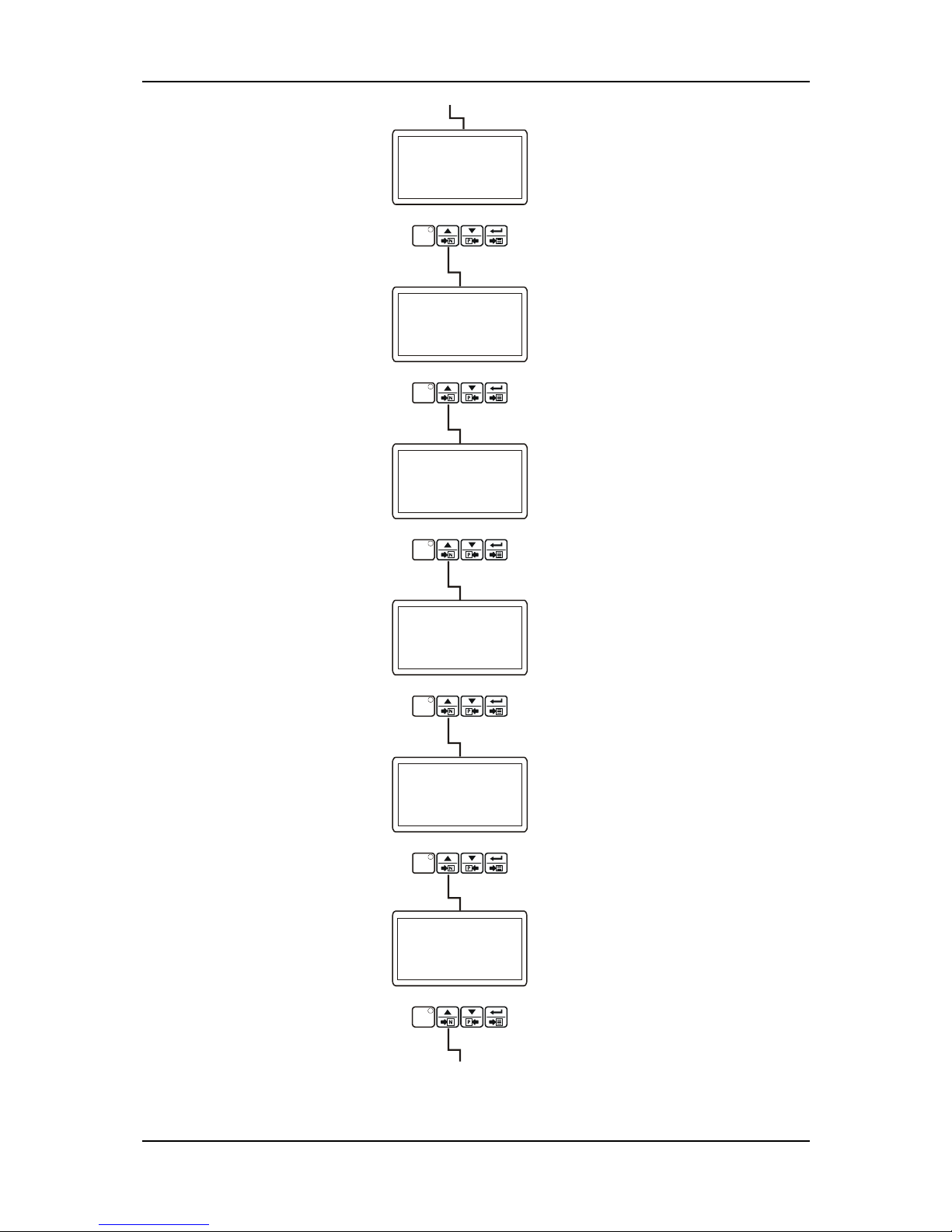
EAOM-210 FLJ.eng / ver 0.0
Pages 30 / 132
TECHNICIAN SECTION
EXP.CONFG.OUT-5 PAGE
PROG
Technician
can access to the former
page by pressing decrement button.
Operator can not access to this page.
Technician can access to the following
page by pressing increment button.
TECHNICIAN SECTION
EXP.CONFG.OUT PAGE
-6
PROG
Technician
can access to the former
page by pressing decrement button.
Operator can not access to this page.
Technician can access to the following
page by pressing increment button.
TECHNICIAN SECTION
EXP.CONFG.OUT PAGE
-7
PROG
Technician
can access to the former
page by pressing decrement button.
Operator can not access to this page.
Technician can access to the following
page by pressing increment button.
TECHNICIAN SECTION
EXP.CONFG.OUT-8 PAGE
PROG
Technician
can access to the former
page by pressing decrement button.
Operator can not access to this page.
Technician can access to the following
page by pressing increment button.
TECHNICIAN SECTION
START TIMERS PAGE
PROG
Technician
can access to the former
page by pressing decrement button.
Operator can not access to this page.
Technician can access to the following
page by pressing increment button.
EXPANSION CONFIGURABLE
OUTPUT-5 Page
If the Expansion Module Selection
parameter in CanBus Configuration
page is disable, this page is ignored.
EXPANSION CONFIGURABLE
OUTPUT-6 Page
If the Expansion Module Selection
parameter in CanBus Configuration
page is disable, this page is ignored.
EXPANSION CONFIGURABLE
OUTPUT-7 Page
If the Expansion Module Selection
parameter in CanBus Configuration
page is disable, this page is ignored.
START TIMERS Page
EXPANSION CONFIGURABLE
OUTPUT-8 Page
If the Expansion Module Selection
parameter in CanBus Configuration
page is disable, this page is ignored.
TECHNICIAN SECTION
LOAD/STP.TIMERS PAGE
PROG
Technician
can access to the former
page by pressing decrement button.
Operator can not access to this page.
Technician can access to the following
page by pressing increment button.
LOAD/STOPPING TIMERS Page
Page 31
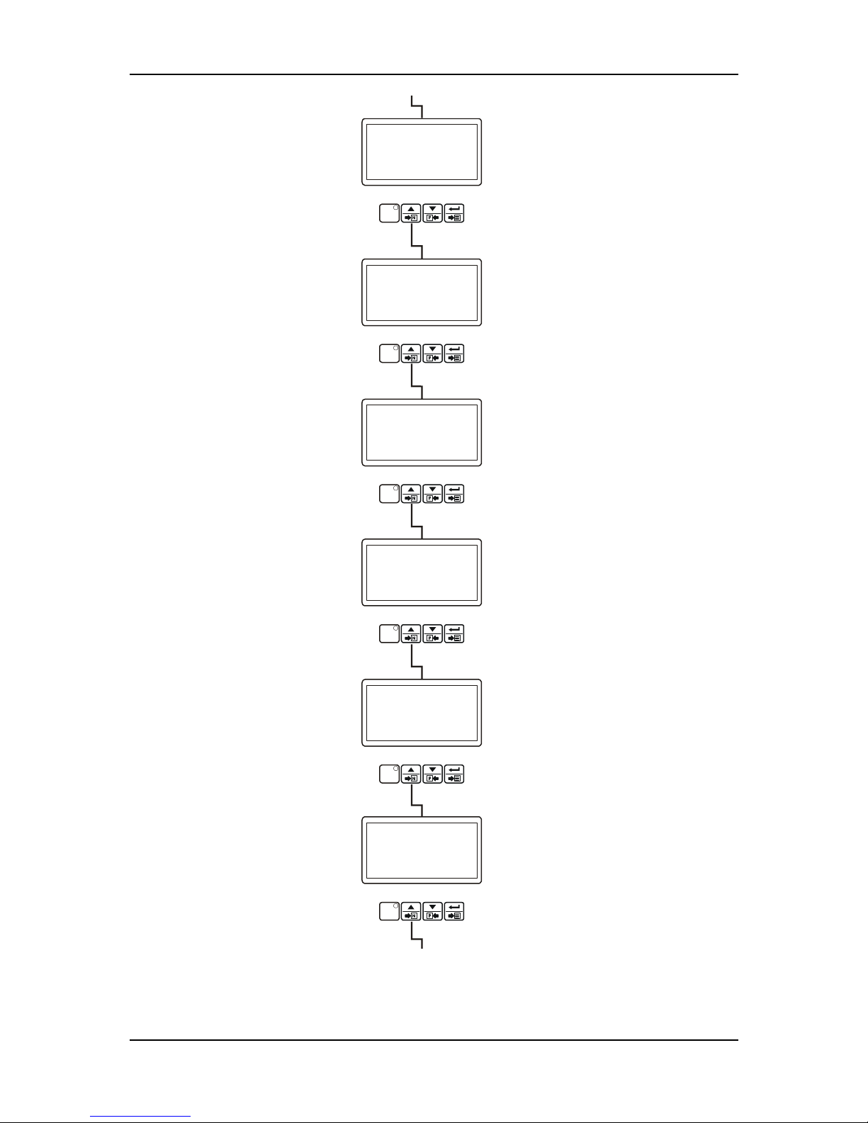
EAOM-210 FLJ.eng / ver 0.0
Pages 31 / 132
TECHNICIAN SECTION
BREAKERS PAGE
PROG
Technician
can access to the former
page by pressing decrement button.
Operator can not access to this page.
Technician can access to the following
page by pressing increment button.
BREAKERS Page
ENGINE MAIN TENANCE ALARM Page
LED-1,2,3 CONFIGURATION Page
COMMUNICATION Page
TECHNICIAN SECTION
LCD CONFIG.PAGE
PROG
Technician
can access to the former
page by pressing decrement button.
Operator can not access to this page.
Technician can access to the following
page by pressing increment button.
TECHNICIAN SECTION
ENG.MAINT.ALARM PAGE
PROG
Technician
can access to the former
page by pressing decrement button.
Operator can not access to this page.
Technician can access to the following
page by pressing increment button.
TECHNICIAN SECTION
COMMUNICATION PAGE
PROG
Technician
can access to the former
page by pressing decrement button.
Operator can not access to this page.
Technician can access to the following
page by pressing increment button.
TECHNICIAN SECTION
CONFIG. LED-123 PAGE
PROG
Technician
can access to the former
page by pressing decrement button.
Operator can not access to this page.
Technician can access to the following
page by pressing increment button.
LCD CONFIGURATION Page
WORKING CALENDAR & EXERCISE
Page
TECHNICIAN SECTION
WR.CALENDR&EXER.PAGE
PROG
Technician
can access to the former
page by pressing decrement button.
Operator can not access to this page.
Technician can access to the following
page by pressing increment button.
Page 32
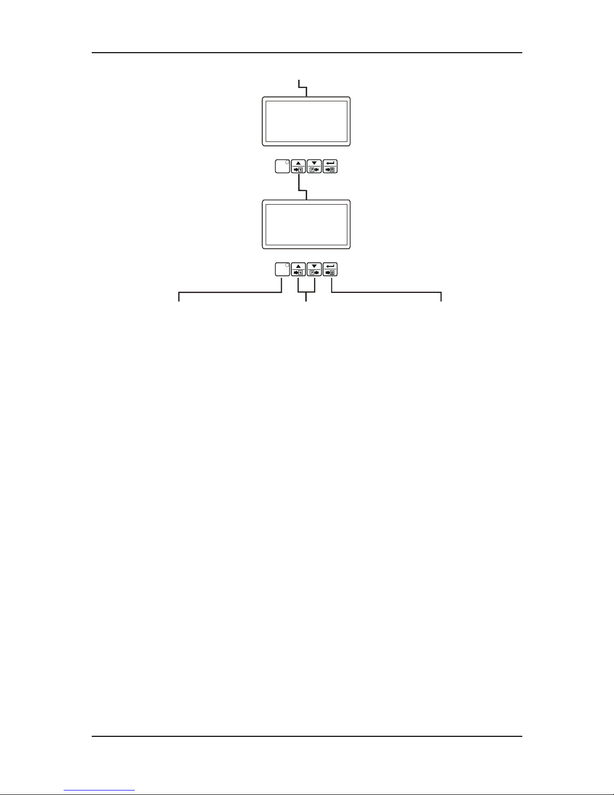
EAOM-210 FLJ.eng / ver 0.0
Pages 32 / 132
DATE SETUP Page
PASSWORD Page
TECHNICIAN SECTION
DATE SETUP PAGE
PROG
Technician
can access to the former
page by pressing decrement button.
Operator can not access to this page.
Technician can access to the following
page by pressing increment button.
TECHNICIAN SECTION
PASSWORD PAGE
PROG
Operator can not access to this page.
Press prog button to exit
from Program Mode and
turn to operation screen.
Continue to press increment and
decrement buttons to change the
page.
By pressing ENTER button,
user can access to all
parameters in related page.
Page 33
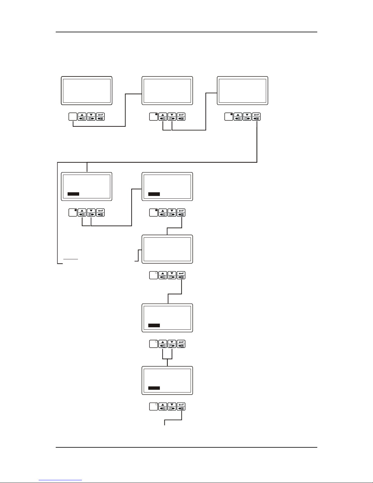
EAOM-210 FLJ.eng / ver 0.0
Pages 33 / 132
3.4.1 Changing and Saving Technician Parameter Values
Example-1 : To change CT Primary parameter in ”GENERATOR CURRENT/POWER ACTIONS
PAGE”, user must access to “GEN.CUR/PW.ACT.PAGE” firstly.
TECHNICIAN SECTION
PROG
When the prog button is
pressed, password is
asked for accessing to
parameters.
PROG
OPERATOR SECTION
PROG
TECHNICIAN PASSWORD
Press the Enter button to
confirm password. If the
password is incorrect, the
unit will drop out of
program mode.
TECHNICIAN SECTION
PASSWORD
162
PROG
User can access to technician parameters
by entering technician password. This
selection is done with increment and
decrement buttons.
Press the Enter button.
TECHNICIAN SECTION
PASSWORD
0
PROG
Enter password with
increment and
decrement buttons.
Note1:
If Enter button is pressed
and the technician password is
zero, Password screen is ignored.
TECHNICIAN SECTION
GEN.CUR/POW.ACT.PAGE
PROG
GENERATOR CURRENT/POWER
ACTIONS Page
Operator can not
access to this page.
TECHNICIAN SECTION
GEN.CUR/POW.ACT.PAGE
CT PRIMARY
Vac 100
PROG
Press Enter button to access to
first parameter in Generator
Current/Power Actions page.
Parameter can be changed with
increment and decrement buttons
Press Enter button to confirm the
changed value and access to the
following parameter.
CT Primary parameter
TECHNICIAN SECTION
GEN.CUR/POW.ACT.PAGE
CT PRIMARY
Vac 500
PROG
Operation Screen
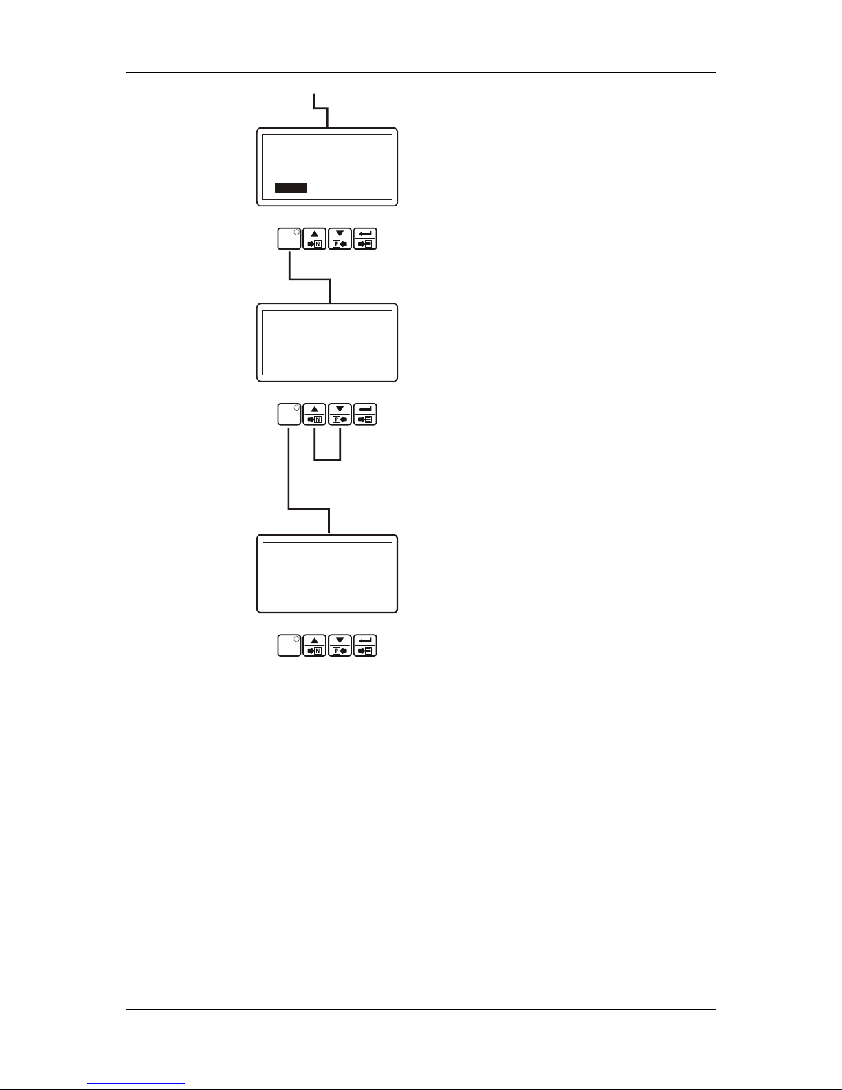
MAINS & LOAD
L12: 380Vac I1: 126A
Fq:50.0Hz
AUTO
L23: 380Vac I2: 126A
L31: 380Vac I3: 126A
IT: 378A
IEA: 63A
CRANKNG ATTEMP
OVER SPEED PREALARM!
Page 34
EAOM-210 FLJ.eng / ver 0.0
Pages 34 / 132
When Prog button is pressed,
related page can be accessed.
If Prog button is pressed
again, operation screen is
shown.
Continue to press increment and decrement
buttons to change the page.
Operation Screen
CT Primary (Earth Fault) parameter
TECHNICIAN SECTION
GEN.CUR/POW.ACT.PAGE
EARTH FAULT CT PRIM
Vac 100
PROG
TECHNICIAN SECTION
GEN.CUR/POW.ACT.PAGE
PROG
GENERATOR CURRENT/POWER
ACTIONS Page
PROG
MAINS & LOAD
L12: 380Vac I1: 126A
Fq:50.0Hz
AUTO
L23: 380Vac I2: 126A
L31: 380Vac I3: 126A
IT: 378A
IEA: 63A
CRANKNG ATTEMP
OVER SPEED PREALARM!
Page 35

EAOM-210 FLJ.eng / ver 0.0
Pages 35 / 132
3.5 Programmable function definitions
Operator parameters
(MAINS LEVELS PAGE) MAINS LEVELS page
MAINS UNDER VOLTAGE Mains Under Voltage
VAC 60 – 600 320
MAINS UNDER V.RET. Mains Under Voltage Return
VAC 60 – 600 340
MAINS OVER VOLTAGE Mains Over Voltage
VAC 60 – 600 440
MAINS OVER V.RETURN Mains Over Voltage Return
VAC 60 – 600 420
MAINS UNDER FREQ. Mains Under Frequency
Hz 20.0 – 75.0 45.0
MAINS UNDER F.RET. Mains Under Frequency Return
Hz 20.0 – 75.0 48.0
MAINS OVER FREQ. Mains Over Frequency
Hz 20.0 – 75.0 55.0
MAINS OVER F.RETURN Mains Over Frequency Return
Hz 20.0 – 75.0 52.0
The unit uses these parameters to decide when to lit the “Mains Okey LED”.
In Automatic mode, the unit uses these parameters to switch the load between the mains
supply and the alternator.
(GEN.VOLT.LEVELS PAGE) GENERATOR VOLTAGE LEVELS page
GEN.UNDER VOLTAGE Generator Under Voltage
VAC (dis)60 – 600 320
GEN.UNDER V.PRE-ALR Generator Under Voltage Pre-Alarm
VAC (dis)60 – 600 340
GEN.LOADING VOLTAGE Generator Loading Voltage
VAC 60 – 600 345
GEN.OVER V.PRE-ALR Generator Over Voltage Pre-Alarm
VAC (dis)60 – 600 420
GEN.OVER V.PR-A.RET Generator Over Voltage Pre-Alarm Return
VAC 60 – 600 400
GEN.OVER VO.SHUTDWN Generator Over Voltage Shutdown
VAC 60 – 600 440
The unit uses these parameters to decide when to display Voltage Failure and Voltage Error
Messages. Also, the unit uses Generator Loading Voltage parameter to decide when to take
the load.
(GEN.FREQ.LEVELS PAGE) GENERATOR FREQUENCY LEVELS page
GEN.UNDER FREQUENCY Generator Under Frequency
Hz (dis)30.0 – 75.0 43.0
GEN.UNDER F.PRE-ALR Generator Under Frequency Pre-Alarm
Hz (dis)30.0 – 75.0 45.0
GEN.LOADING FREQ. Generator Loading Frequency
Hz 30.0 – 75.0 46.0
GEN.OVER F.PRE-ALR Generator Over Frequency Pre-Alarm
Hz (dis)30.0 – 75.0 55.0
GEN.OVER F.PR-A.RET Generator Over Frq Pre-Alarm Return
Hz 30.0 – 75.0 54.0
GEN.OVER FR.SHUTDWN Generator Over Frequency Shutdown
Hz (dis)30.0 – 75.0 58.0
The unit uses these parameters to decide when to display Speed Failure and Frequency
Error Messages. Also, the unit uses Generator Loading Frequency parameter to decide
when to take the load.
(GEN.CUR/POW.LVL.PAGE) GENERATOR CURRENT/POWER LEVELS page
GEN.OVER CURRENT Generator Over Current
A AC 0 – 9999 9999
GEN.SHORT CIRCUIT Generator Short Circuit
A AC 0 – 9999 9999
GEN.EARTH FAULT Generator Earth Fault
A AC 0 – 9999 100
Page 36

EAOM-210 FLJ.eng / ver 0.0
Pages 36 / 132
Technician parameters
(GEN.CUR/POW.ACT.PAGE) GENERATOR CURRENT/POWER ACTIONS page
CT PRIMARY CT Primary
A AC 0 – 9999 500
EARTH FAULT CT PRIM CT Primary (Earth Fault)
A AC 0 – 9999 500
OVER CUR.ACTIONS
Over Current Actions
-Disable
-Warning (Alarm Only, No Shutdown)
-Electrical Trip (Alarm/Off Load Generator
Followed By Shutdown After Cooling)
-Shutdown (Alarm And Shutdown)
-
0-3 dis
OVER CUR.ALARM TIME Over Current Alarm Time
Sec 0 - 99 0
SHORT CIR.ACTIONS
Short Circuit Actions
-Disable
-Warning (Alarm Only, No Shutdown)
-Electrical Trip (Alarm/Off Load Generator
Followed By Shutdown After Cooling)
-Shutdown (Alarm And Shutdown)
-
0-3 dis
SHORT CIR.ALRM TIME Short Circuit Alarm Time
Sec 0 - 99 0
EARTH FAULT ACTIONS
Earth Fault Actions
-Disable
-Warning (Alarm Only, No Shutdown)
-Electrical Trip (Alarm/Off Load Generator
Followed By Shutdown After Cooling)
-Shutdown (Alarm And Shutdown)
-
0-3 dis
EARTH FAU.ALRM TIME Earth Fault Alarm Time
Sec 0 - 99 0
(MISCELLANEOUS PAGE) MISCELLANEOUS page
SENS.OPT.GEN.F.ENAB Sensing Options Generator Frq En/Dis
-
ENAB DIS ENAB
SNS.OP.PICKP ENA&FW Sensing Opt Pickup En/Dis & Flywheel
-
(dis)0-1000 DIS
AC SYSTEM
Ac System:
0= 1phase 2wire,
1= 3phase 4wire,
2= 3phase 4wire Series Delta,
3= 1phase 3wire
-
0-3 1
FAST LOAD.FEAT.ENAB Fast Loading Feature En/Dis
-
ENAB DIS DIS
ALL WRN.ARE LTCH.EN All Warnings Are Latched En/Dis
-
ENAB DIS DIS
MAINS FAIL.DETEC.EN Mains Failure Detection En/Dis
-
ENAB DIS ENAB
LK.MA.FA.FO.MA.CN.E
Look Mains Failure For Mains Cont.
En/Dis
-
ENAB DIS DIS
GAS/DIESEL SELECT Engine Fuel (Gas/ Diesel) Selection
-
GAS/ DIESEL DIESEL
STOP/FUEL SELECTION Stop / Fuel Selection
-
STOP/FUEL FUEL
STOP SOLENOID TIME Stop Solenoid Time
Sec 5 - 99 20
IGNITION DELAY Ignition Delay
Sec 1 - 99 5
GAS VALVE DELAY Gas Valve Delay
Sec 1 - 99 5
MIN.IGNITION SPEED Min Ignition Speed
RPM 10 - 1500 200
NOMINAL FREQUENCY Nominal Alternator Frequency
Hz 30.0 – 75.0 50.0
NOMINAL SPEED Nominal Speed
RPM 500 - 5000 3000
VOLT TRANSFRM RATIO Voltage Transformer Ratio
1 - 50 1
SENSING OPTIONS GENERATOR FRQ EN/DIS:
ENABLE: Speed sensing will be derived from the generator output frequency.
DISABLE: Speed sensing not will be derived from the generator output frequency.
SENSING OPT. PICKUP EN/DIS & FLYWHEEL
DISABLE: Speed sensing will not be derived from the magnetic pickup.
1-1000: Speed sensing will be derived from the magnetic pickup and the number is flywheel
teeth on the engine.
Page 37

EAOM-210 FLJ.eng / ver 0.0
Pages 37 / 132
AC SYSTEM 3 PHASE 4 WIRE OR 1 PHASE 2 WIRE
0: AC system is 1 phase 2 wire.
1: AC system is 3 phase 4 wire.
2: AC system is 3 phase 4 wire series delta.
3: AC system is 1 phase 3 wire.
FAST LOADING FEATURE EN/DIS
ENABLE: The module will terminate the safety on timer once all monitored parameters have
reached their normal settings. This feature is useful if the module is to be used as a standby
controller as it allows the generator to start and go on load in the shortest possible time.
DISABLE: Normal operation, the safety on timer will be observed in full. This feature is useful
if the module is to be used with some small engines where pre-mature termination of the
delay timer can lead to over speed alarms on start up.
ALL WARNINGS ARE LATCHED EN/DIS
Disable: Normal operation, the warnings and pre-alarms (except spare inputs, because they
have their latching or non-latching selections) will automatically reset once the triggering
condition has cleared.
Enable: Warnings and pre-alarms will latched when triggered. To reset the alarm either an
external reset must be applied to one of the inputs or the ‘Reset’ pushbutton operated, once
the triggering condition has cleared.
MAINS FAILURE DETECTION EN/DIS
Disable: The module will not monitor the AC mains supply for failure. The AC mains
instrumentation will still be active however.
Enable: The module will monitor the incoming AC mains supply. Should the supply go out
side of limits the module will initiate its automatic mains failure sequence.
LOOK MAINS FAILURE FOR MAINS CONTACTOR EN/DIS
Disable: In the event of a mains failure the EAOM-210 FLJ will attempt to maintain the supply
to the load for the incoming AC mains supply until the generator is available to go on load. In
the event of a generator failure the module will default back to the incoming AC mains
supply. This provides a ‘fail-safe system’, ensuring that in the event of a system failure the
load will still be fed from the AC mains supply.
Enable: As soon as the module detects a mains failure the mains contactor or breaker relay
will be opened to remove the supply from the load. This is to prevent damage to the load in
case of single-phase failure, especially useful if the load is a 3-phase motor or pump. The
supply to the load will then be fed from the gen-set once it is available. In the event of
generator failure the module will open the generator relay and remove the supply to the load
until either the mains supply is restored or the generator is restarted.
ENGINE FUEL (DIESEL /GAS) SELECTION
Diesel or Gas engine can be selected.
If diesel engine selected:
STOP/FUEL SELECTION
Selection for the engine has Fuel or Stop solenoid.
STOP SOLEONID TIME
This timer is used if the unit is configured to operate an Energise to stop engine. It dictates
the duration that the Stop Solenoid output will remain active after the module has detected
the engine has come to rest. If the Stop Solenoid output is not configured, this timer will still
operate, preventing an immediate restart.
Page 38

EAOM-210 FLJ.eng / ver 0.0
Pages 38 / 132
Example: Start/stop diagram for Diesel Engine.
The formula signs and indices mean:
TPT Preheating time [s]
TCT Engagement time [s]
TRT Interval between 2 start attempts [s]
TDT Engine delayed monitoring [s]
Page 39
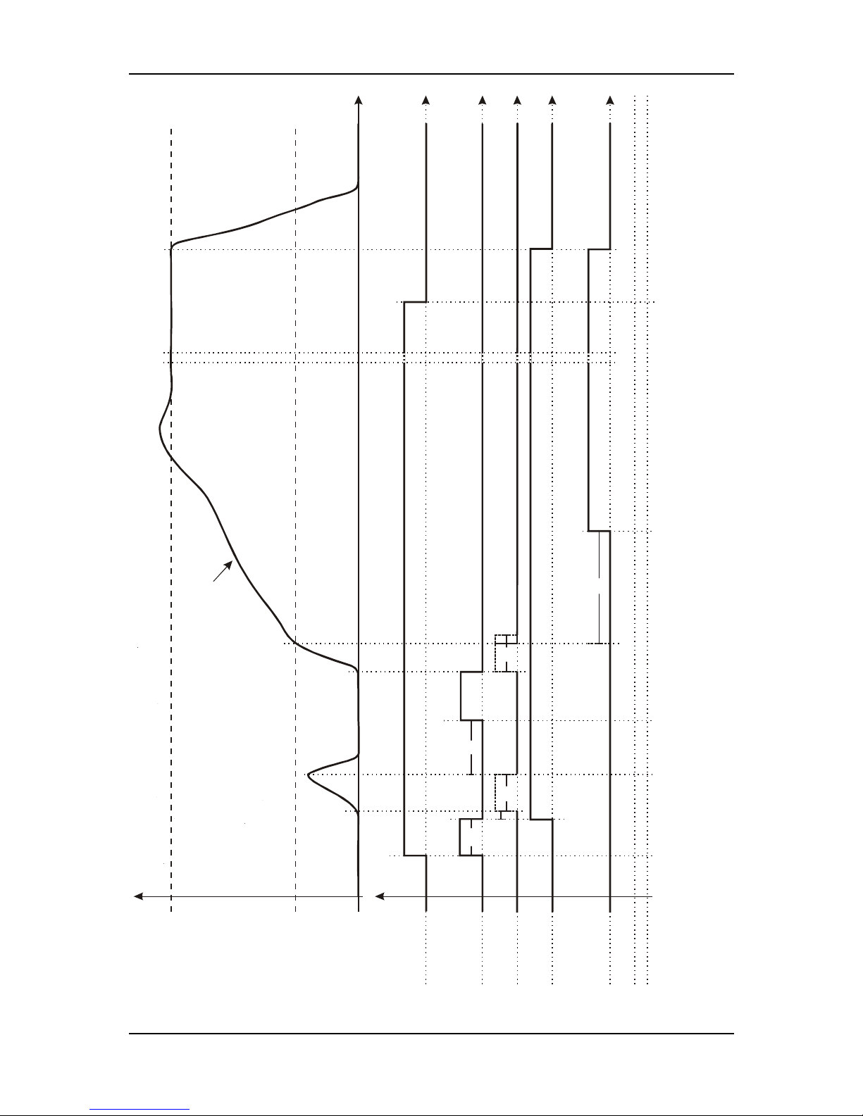
EAOM-210 FLJ.eng / ver 0.0
Pages 39 / 132
Start request
Pre-heat
Starter
Fuel relay
Engine
monitoring ON
Rated speed
[
R
P
M
]
t
[
s
]
Starting Unsuccessful
Successful
S
t
o
p
p
i
n
g
t
PT
2s
[1/min ];RPM
t
[
s
]
t
[
s
]
t
[
s
]
t
[
s
]
t
[
s
]
t
RT
t
CT
t
CT
t
DT
Crank disconnect
magnetic pick-up speed
Page 40

EAOM-210 FLJ.eng / ver 0.0
Pages 40 / 132
If gas engine selected:
IGNITION DELAY
With gas engines often a purging operation is desired before starting. With the engaging of
the starter the ignition delay is started. If the ‘min ignition speed’ is reached after expiry of
this time, the configurable relay output ‘ignition’ is set.
GAS VALVE DELAY
By setting the ignition relay the gas valve delay is started. After the expiry of the set time as
long as the number of revolutions is higher than the minimum ignition speed, the gas valve is
set. When the necessary engine shutdown process, gas valve is de-energised.
MIN IGNITION SPEED
After expiry of the ignition delay the number of revolutions set must be reached, so that the
configurable relay output ‘ignition’ will be set.
Example: Start/stop diagram for Gas Engine.
The formula signs and indices mean:
T
RT
Interval between 2 start attempts [s]
T
IT
Ignition delay [s]
T
GT
Gas valve delay [s]
T
DT
Engine delayed monitoring [s]
Page 41
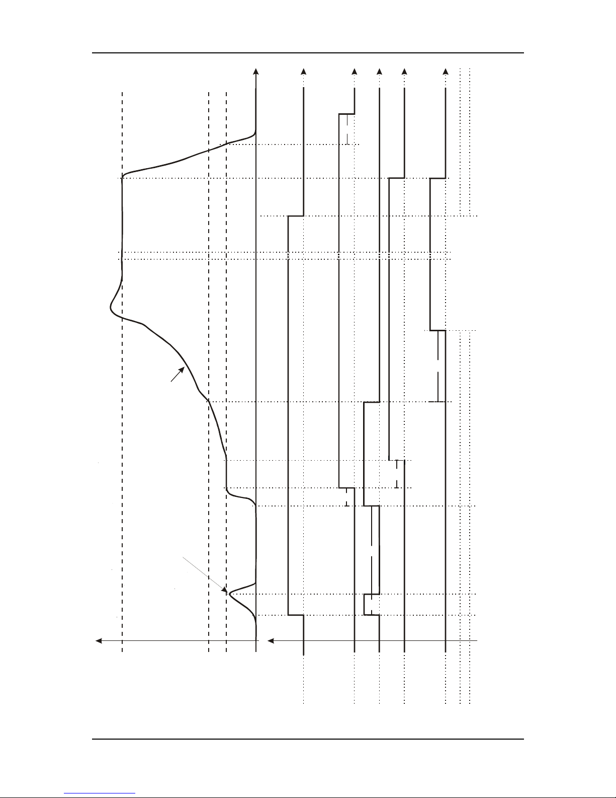
EAOM-210 FLJ.eng / ver 0.0
Pages 41 / 132
Start request
Ignition
Starter
Gas valve
Engine
monitoring ON
Minimum ignition speed
Rated speed
[
R
P
M
]
t
[
s
]
t
[
s
]
t
[
s
]
Starting
S
t
o
p
p
i
n
g
Minimum ignition speed
will not be reached
[1/min ];RPM
5
s
Unsucce ssful
Successful
t
[
s
]
t
[
s
]
t
[
s
]
t
IT
t
IT
t
RT
t
GT
t
DT
Crank disconnect
magnetic pick-up speed
Page 42
EAOM-210 FLJ.eng / ver 0.0
Pages 42 / 132
NOMINAL FREQUENCY
This parameter used for calculate the engine speed (Rpm) from alternator frequency or
calculate the alternator frequency from engine speed (Rpm).
NOMINAL SPEED
This parameter used for calculate the engine speed (Rpm) from alternator frequency or
calculate the alternator frequency from engine speed (Rpm).
VOLTAGE TRANSFORMER RATIO
1-50: Defines the scaling factor applied to voltage readout and associated fault conditions.
This VT ratio is for additional voltage transformers mounted the unit.
(ENGINE STAR.OPT PAGE) ENGINE STARTING OPTIONS page
AU.ALR.PRIOR STRT.E Audible Alarm Prior To Starting En/Dis
- ENAB DIS DIS
NUMBR OF STR.ATTEMP Number Of Start Attempts
- 1 – 10 3
CRANKING TIME Cranking Time
SEC 1 – 99 5
CRANK REST TIME Crank Rest Time
SEC 5 – 99 10
MUL.STR.ENG.ATEMP.E Multiple Start Engage Attempts E/D (Pick)
- ENAB DIS DIS
ENGAGE ATTEMPT TIME Engage Attempt Time (Pickup)
SEC 0.1 – 10.0 1.0
ENG.ATEMP.REST TIME
Engage Attempt Rest Time (Pickup)
SEC 0.1 – 10.0 1.0
PICK.SNSR FAIL DELY Pickup Sensor Fail Delay(Pickup)
SEC 0.1 – 10.0 1.0
AUDIBLE ALARM PRIOR TO STARTING EN/DIS
ENABLE: The audible alarm will sound before the engine starts. The sounder will become
active once the start delay is initialised, it will remain active until either the engine reaches
crank disconnect speed or pre-heat timers are cancelled.
NUMBER OF START ATTEMPTS
This value is the number of times the module will attempt to start the generator. Should the
generator start the module will not attempt further starts. If the generator does not start after
the final attempt, the module will give a ‘Fail to start’ alarm.
CRANKING TIME
This is the maximum amount of time that the module will energise the starter motor for during
starting attempts once the starter has engaged.
CRANK REST TIME
This is the amount of time the module will wait for between start attempts. This is to allow the
starter motor to cool and the starter batteries to recover.
MULTIPLE START ENGAGE ATTEMPTS E/D
(Only available if using Magnetic pickup)
ENABLE: The module will monitor the flywheel to ensure that the starter motor has engaged.
If it detects the starter has not meshed, it will de-energise the start relay and after a short
delay it will attempt to re-engage the starter. This will be repeated until either the starter
motor engages correctly or the number of engage attempts expires. Each start attempt can
have a maximum number of attempts to engage the starter, this value is entered the box.
DISABLE: Normal operation, starter engagement with flywheel will not monitored.
ENGAGE ATTEMPT TIME
(Only available if using Magnetic pickup and multiple engage attempts)
This timer dictates the duration that the module will attempt to engage the starter motor
during each engage attempt. If the magnetic pickup is not detecting movement of the
flywheel when this timer expires the engage attempt will terminate. Once all engage attempts
have been made the module will generate ‘Fail to engage’ alarm.
Page 43
EAOM-210 FLJ.eng / ver 0.0
Pages 43 / 132
ENGAGE ATTEMPT REST TIME
(Only available if using Magnetic pickup and multiple engage attempts)
This timer dictates the duration that the module will wait between attempts to engage the
starter.
PICKUP SENSOR FAIL DELAY
(Only available if using Magnetic pickup without multiple engage attempts)
This is only used if magnetic pickup speed sensing is selected. When cranking, the module
must receive a speed signal within this time. If no signal is present the generator will be
shutdown and Loss of Speed Sensing alarm given.
(ENG.CRANK DISCN.PAGE) ENGINE CRANK DISCONNECT page
CRNK DISCN.ON GEN.F Crank Disconnect On Gen. Frequency
Hz 25.0 – 75.0 30.0
CRNK DISCN.ON MAG.P Crank Disconnect On Magnetic Pickup
RPM 500-6000 500
CRNK DISCN.ON GEN.V Crank Disconnect On Gen. Voltage
VAC (dis)60 – 600 300
CRNK DISC.ON CH.G.V Crank Disconnect On Charge Alt. Voltage
VDC (dis)6.0 – 30.0 dis
CRNK DISCN.ON OIL P Crank Disconnect On Oil Pressure
BAR (dis)1.0-90.0 dis
The parameters in this page are used for engine started signals. If any of the selected
signals appears, the unit assumes that the engine has started.
CRANK DISCONNECT ON GENERATOR FREQUENCY
If the generator frequency over than 30.0 Hz, the unit assumes that the engine has started
and the unit stop cranking.
CRANK DISCONNECT ON MAGNETIC PICKUP
If the generator speed over than 500 Rpm, the unit assumes that the engine has started and
the unit stop cranking.
CRANK DISCONNECT ON GENERATOR VOLTAGE
If the generator voltage over than 300 Vac, the unit assumes that the engine has started and
the unit stop cranking.
CRANK DISCONNECT ON CHARGE GEN. VOLTAGE
If the charge alternator voltage over than 6.1 Vdc, the unit assumes that the engine has
started and the unit stop cranking. Note: If the charge generator input (terminal #15) is
disconnect, this parameter selected as disabled (6.0 Vdc).
CRANK DISCONNECT ON OIL PRESSURE
If the oil pressure sender over than this value or the oil pressure digital input (terminal #18) is
not switched to -Battery, the unit assumes that the engine has started and the unit stop
cranking.
(GEN.SPED SETING PAGE) GENERATOR SPEED SETTINGS page
GEN.UNDER SPEED Generator Under Speed
RPM (dis)500 – 5000 500
GEN.UNDR SPED PRE-A Generator Under Speed Prealarm
RPM (dis) 500 – 5000 500
GEN.UNDR SP.PR-A.RT Generator Under Speed Prealarm Return
RPM 500 – 5000 500
GEN.OVER SPED PRE-A Generator Over Speed Prealarm
RPM (dis) 500 – 5000 500
GEN.OVER SP.PR-A.RT Generator Over Speed Prealarm Return
RPM 500 – 5000 500
GEN.OVER SP.SHUTDWN Generator Over Speed Shutdown
RPM (dis) 500 – 5000 500
The parameters in this page are used for the generator speed low and high alarms.
Page 44

EAOM-210 FLJ.eng / ver 0.0
Pages 44 / 132
(ENG.PLANT BATTR PAGE) ENGINE PLANT BATTERY page
BAT.UNDER V.WARNING Battery Undervolts Warning
VDC (dis)6.0 – 30.0 10.0
BAT.UNDR V.WARN.RET Battery Undervolts Warning Return
VDC 6.0 – 30.0 10.5
BAT.UNDER VOL.DELAY Batt Undervolts Volts Delay
Sec 0 – 9.9 1.0
BAT.OVER V.WARNING Battery Overvolts Warning
VDC (dis)6.0 – 30.0 30.0
BAT.OVER V.WARN.RET Battery Overvolts Warning Return
VDC 6.0 – 30.0 29.5
BAT.OVER VOL.DELAY Batt Overvolts Delay
sec 0 – 9.9 1.0
CHARGE ALT.WARNING Charge Alternator Warning
VDC (dis)6.0 – 30.0 6.1
The parameters in this page are used for the battery voltage low and high alarms and the
charge alternator voltage warning.
(ANALOGUE INPUTS PAGE) ANALOGUE INPUTS page
OIL PRES.INPUT TYPE Oil Pressure Input Type
Dis,nc,no,anlg ANLG
OIL PRES.PRE-ALARM Oil Pressure Pre-Alarm
BAR (dis)0.0 – 99.9 1.2
OIL PRES.PRE-AL.RET Oil Pressure Pre-Alarm Return
BAR 0.0 – 99.9 1.4
OIL PRES.SHUTDOWN Oil Pressure Shutdown
BAR 0.0 – 99.9 1.0
TEMP.INPUT TYPE Temperature Input Type
Dis,nc,no,anlg ANLG
TEMP.PRE-ALARM Temperature Pre-Alarm
C (dis)0 - 300 90
TEMP.PRE-ALARM RET Temperature Pre-Alarm Return
C 0 - 300 88
TEMP.SHUTDDOWN Temperature Shutdown
C 0 - 300 95
LEVEL PRE-ALARM Level Pre-Alarm
% (dis)0 - 300 80
LEVEL PRE-ALARM RET Level Pre-Alarm Return
% 0 - 300 90
LEVEL SHUTDOWN Level Shutdown
% (dis)0 - 300 70
The parameters in this page are used for the oil pressure (terminal #12), coolant temperature
(terminal #11) and fuel level (terminal #10) senders alarms.
OIL PRESSURE INPUT TYPE
This section is used to configure the Oil Pressure sender input.
dıS: The Oil Pressure input will not be monitored.
1: digital & closed for low oil pressure : The Oil pressure input is fed from an engine
mounted digital pressure switch. This switch returns a closed signal during low oil pressure
conditions (and engine at rest), once oil pressure is established the switch will open.
2: digital & open for low oil pressure : The Oil pressure input is fed from an engine
mounted digital pressure switch. This switch returns an open signal during low oil pressure
conditions (and engine at rest), once oil pressure is established the switch will close.
3: analogue : The Oil pressure input is connected to a resistive type engine mounted oil
pressure transducer.
TEMPERATURE INPUT TYPE
This section is used to configure the Coolant Temperature sender input.
dıS: The Coolant Temperature input will not be monitored.
1: digital & normally closed : The Coolant Temperature input is fed from an engine
mounted digital temperature switch. This switch returns a closed signal during low
temperature, should the temperature rise above the switch manufacturers trip point the
switch contact will open.
2: digital & normally open : The Coolant Temperature input is fed from an engine mounted
digital temperature switch. This switch returns an open signal during low temperature, should
the temperature rise above the switch manufacturers trip point the switch contact will close.
3: analogue : The Oil pressure input is connected to a resistive type engine mounted
temperature transducer.
Note: If the Level Pre-alarm and Level Shutdown parameters are selected as disable, the
Level showing is ignored.
Page 45

EAOM-210 FLJ.eng / ver 0.0
Pages 45 / 132
(ANALG.SENDR LIN.PAGE) ANALOGUE SENDER LINEARISATIONS page
OIL PRESS.SENDER 0 Oil Pressure Sender 0
R 0 -650 10
OIL PRESSURE 0 Oil Pressure 0
BAR 0 – 99.9 0.0
OIL PRESS.SENDER 1 Oil Pressure Sender 1
R 0 -650 62
OIL PRESSURE 1 Oil Pressure 1
BAR 0 –99.9 2.0
OIL PRESS.SENDER 2 Oil Pressure Sender 2
R 0 -650 111
OIL PRESSURE 2 Oil Pressure 2
BAR 0 –99.9 4.0
OIL PRESS.SENDER 3 Oil Pressure Sender 3
R 0 -650 156
OIL PRESSURE 3 Oil Pressure 3
BAR 0 –99.9 6.0
OIL PRESS.SENDER 4 Oil Pressure Sender 4
R 0 -650 205
OIL PRESSURE 4 Oil Pressure 4
BAR 0 –99.9 10.0
TEMP.SENDER 0 Temperature Sender 0
R 0 -650 360
TEMPERATURE 0 Temperature 0
C 0 -300 34
TEMP.SENDER 1 Temperature Sender 1
R 0 -650 145
TEMPERATURE 1 Temperature 1
C 0 -300 54
TEMP.SENDER 2 Temperature Sender 2
R 0 -650 50
TEMPERATURE 2 Temperature 2
C 0 -300 84
TEMP.SENDER 3 Temperature Sender 3
R 0 -650 43
TEMPERATURE 3 Temperature 3
C 0 -300 100
TEMP.SENDER 4 Temperature Sender 4
R 0 -650 10
TEMPERATURE 4 Temperature 4
C 0 -300 150
LEVEL SENDER 0 Level Sender 0
R 0 -650 10
LEVEL 0 Level 0
- 0 -300 0
LEVEL SENDER 1 Level Sender 1
R 0 -650 40
LEVEL 1 Level 1
- 0 -300 25
LEVEL SENDER 2 Level Sender 2
R 0 -650 80
LEVEL 2 Level 2
- 0 -300 50
LEVEL SENDER 3 Level Sender 3
R 0 -650 140
LEVEL 3 Level 3
- 0 -300 75
LEVEL SENDER 4 Level Sender 4
R 0 -650 185
LEVEL 4 Level 4
- 0 -300 100
Page 46

EAOM-210 FLJ.eng / ver 0.0
Pages 46 / 132
(CANBUS CONFIG. PAGE) CANBUS CONFIGURATION page
EXPAN. MODULE SELECT Expansion I/O Module Selection
ENAB / DIS DIS
BAUD RATE Baud Rate:
0- 20
1- 50
2- 100
3- 125
4- 250
5- 500
6- 800
7- 1.000
kBaud
0 - 7 4
DEVICE TYPE J1939 ECU Type Selection:
0- Disable
1- Standard
2- Volvo EMS2
3- Volvo EDC4
4- Perkins
(dis)0 - 4 DIS
DEVICE ADDRESS Device Address
0 - 255 17
ENGINE CONT.ADDRESS Engine Control Address
0 - 255 0
ECU REMOTE CONTROL ECU Remote Control via J1939
ENAB / DIS DIS
SENDING DM3 MESSAGE Reset Previously Active DTCs – DM3
No / Yes No
SPEED CONTROL ENAB Speed Control via J1939
ENAB / DIS DIS
OIL PRESS.CONT ENAB Oil Pressure Control via J1939
ENAB / DIS DIS
TEMPER.CONTROL ENAB Coolant Temperature Control via J1939
ENAB / DIS DIS
EXPANSION I/O MODULE SELECTION
If the Expansion I/O module is plugged the unit, this parameter must selected as “Enable”.
BAUD RATE
This parameter defines the used Baud rate. Note: all participants on the CAN bus must use
the same Baud rate.
DEVICE TYPE
The J1939 interface of this unit can be operated with different ECUs. This parameter
determines the operating mode of the used ECUs.
Note: if this parameter is selected as “disable”, No messages will be sent or received.
DEVICE ADDRESS
The unit sends J1939 request and control messages with this ID. It must be
changed for different ECU types according to the following table. The ECU
listens only to control messages, if they are sent to the correct address.
Volvo EMS2 Volvo EDC4 Perkins
17 3 43
Note: Changing above mentioned parameter becomes only effective after restarting the unit.
ENGINE CONTROL ADDRESS
This parameter configures the address of the J1939 ECU, which is controlled.
ECU REMOTE CONTROL via J1939
If this parameter is selected as “Enable”, The unit sends remote start/stop messages to the
ECU if the selected ECU type is supporting the J1939 Remote control Messages. Available
messages are engine start or stop. For some ECUs;
Parameter
Volvo
EMS2
Volvo
EDC4
Perkins Standard
Remote Start
Yes No No No
Remote Stop
Yes No No No
Page 47

EAOM-210 FLJ.eng / ver 0.0
Pages 47 / 132
If this parameter is selected as “Disable”, The ECU remote control via the J1939 protocol will
be disabled.
RESET PREVIOUSLY ACTIVE DTCs – DM3
If this parameter is selected as “Yes”, a DM3 message "Acknowledge passive faults" is
sent. After this parameter is reset automatically to “No”.
SPEED CONTROL via J1939
If this parameter is selected as “Enable”, The speed sensing from J1939 ECU will be used for
the speed (Rpm) failures.
OIL PRESSURE CONTROL via J1939
If this parameter is selected as “Enable”, The oil pressure sensing from J1939 ECU will be
used for the oil pressure failures and the engine started signal.
COOLANT TEMPERATURE CONTROL via J1939
If this parameter is selected as “Enable”, The coolant temperature sensing from J1939 ECU
will be used for the coolant temperature failures.
(CAN ERROR SET PAGE) CAN BUS & J19139 ERROR ACTIONS page
CAN FAULT ACTIONS
Can Fault Actions:
0- Disable
1- Warning Non-Latching
2- Warning (Alarm Only, No Shutdown)
3- Electrical Trip (Alarm/Off Load
Generator Followed By Shutdown After
Cooling)
4- Shutdown (Alarm And Shutdown)
(dis)0-4 dis
CAN FAULT ACTIV.
Can Fault Activation:
0- Active From Starting
1- Active From Safety On
2- Always Active
0 – 2 2
CAN FAULT DELAY Can Fault Delay
Sec 2 - 250 10
AMBER WARN ACTIONS
J1939 Amber Warning Lamp Actions:
0- Disable
1- Warning Non-Latching
2- Warning (Alarm Only, No Shutdown)
3- Electrical Trip (Alarm/Off Load
Generator Followed By Shutdown After
Cooling)
4- Shutdown (Alarm And Shutdown)
(dis)0-4 dis
AMBER WARN ACTIV.
J1939 Amber Warning Lamp Activation:
0- Active From Starting
1- Active From Safety On
2- Always Active
0 – 2 2
AMBER WARN DELAY J1939 Amber Warning Lamp Delay
Sec 0 - 250 2
RED STOP ACTIONS
J1939 Red Stop Lamp Actions:
0- Disable
1- Warning Non-Latching
2- Warning (Alarm Only, No Shutdown)
3- Electrical Trip (Alarm/Off Load
Generator Followed By Shutdown After
Cooling)
4- Shutdown (Alarm And Shutdown)
(dis)0-4 dis
RED STOP ACTIVATION
J1939 Red Stop Lamp Activation:
0- Active From Starting
1- Active From Safety On
2- Always Active
0 – 2 2
RED STOP DELAY J1939 Red Stop Lamp Delay
Sec 0 - 250 2
Page 48

EAOM-210 FLJ.eng / ver 0.0
Pages 48 / 132
(DIG.CNF.INPUT-1 PAGE) DIGITAL CONFIGURABLE INPUT (1) page
DIS,USERCNF.OR LIST
0- Disable
1- User Configured
2- Select From List
(dis)0 - 2 1
POLARITY
0- Normally Open (Close To Activate)
1- Normally Close (Open To Activate)
0 - 1 0
INDICATION
If User Configured
0- Status
1- Warning Non-Latching
2- Warning Latching
3- Electrical Trip
4- Shutdown
0 – 4 0
ACTIVATION
If User Configured
0- Active From Starting
1- Active From Safety On
2- Always Active
0 – 2 2
SELECT FROM LIST
If Select From List
0 Remote Start
1 Auxiliary Mains Fail
2 Simulate Lamp Test Button
3 Simulate Horn Reset Button
4 Simulate Alarm Reset Button
5 Simulate Off Button
6 Simulate Auto Button
7 Simulate Test Button
8 Simulate Manual Button
9 Simulate Start Button
10 Simulate Stop Button
11 Generator Closed Auxiliary
12 Generator Load Inhibit
13 Mains Closed Auxiliary
14 Mains Load Inhibit
15 Auto Restore Inhibit
16 Auto Start Inhibit
17 Panel Lock
18 Scheduled Runs Inhibited
19 Reset Maintenance Alarm
20 Transfer To Generator/Open Mains
21 Transfer To Mains/Open Generator
22 Remote Inhibit
23 Test on Load
24 Generator is supplying the load in OFF
mode
0 – 24 2
INPUT TIME DELAY Input active delay
SEC 0 - 250 5
Page 49

EAOM-210 FLJ.eng / ver 0.0
Pages 49 / 132
(DIG.CNF.INPUT-2 PAGE) DIGITAL CONFIGURABLE INPUT (2) page
DIS,USERCNF.OR LIST
0- Disable
1- User Configured
2- Select From List
(dis)0 - 2 1
POLARITY
0- Normally Open (Close To Activate)
1- Normally Close (Open To Activate)
0 - 1 0
INDICATION
If User Configured
0- Status
1- Warning Non-Latching
2- Warning Latching
3- Electrical Trip
4- Shutdown
0 – 4 0
ACTIVATION
If User Configured
0- Active From Starting
1- Active From Safety On
2- Always Active
0 – 2 2
SELECT FROM LIST
If Select From List
0 Remote Start
1 Auxiliary Mains Fail
2 Simulate Lamp Test Button
3 Simulate Horn Reset Button
4 Simulate Alarm Reset Button
5 Simulate Off Button
6 Simulate Auto Button
7 Simulate Test Button
8 Simulate Manual Button
9 Simulate Start Button
10 Simulate Stop Button
11 Generator Closed Auxiliary
12 Generator Load Inhibit
13 Mains Closed Auxiliary
14 Mains Load Inhibit
15 Auto Restore Inhibit
16 Auto Start Inhibit
17 Panel Lock
18 Scheduled Runs Inhibited
19 Reset Maintenance Alarm
20 Transfer To Generator/Open Mains
21 Transfer To Mains/Open Generator
22 Remote Inhibit
23 Test on Load
24 Generator is supplying the load in OFF
mode
0 – 24 3
INPUT TIME DELAY Input active delay
SEC 0 - 250 5
Page 50

EAOM-210 FLJ.eng / ver 0.0
Pages 50 / 132
(DIG.CNF.INPUT-3 PAGE) DIGITAL CONFIGURABLE INPUT (3) page
DIS,USERCNF.OR LIST
0- Disable
1- User Configured
2- Select From List
(dis)0 - 2 1
POLARITY
0- Normally Open (Close To Activate)
1- Normally Close (Open To Activate)
0 - 1 0
INDICATION
If User Configured
0- Status
1- Warning Non-Latching
2- Warning Latching
3- Electrical Trip
4- Shutdown
0 – 4 0
ACTIVATION
If User Configured
0- Active From Starting
1- Active From Safety On
2- Always Active
0 – 2 2
SELECT FROM LIST
If Select From List
0 Remote Start
1 Auxiliary Mains Fail
2 Simulate Lamp Test Button
3 Simulate Horn Reset Button
4 Simulate Alarm Reset Button
5 Simulate Off Button
6 Simulate Auto Button
7 Simulate Test Button
8 Simulate Manual Button
9 Simulate Start Button
10 Simulate Stop Button
11 Generator Closed Auxiliary
12 Generator Load Inhibit
13 Mains Closed Auxiliary
14 Mains Load Inhibit
15 Auto Restore Inhibit
16 Auto Start Inhibit
17 Panel Lock
18 Scheduled Runs Inhibited
19 Reset Maintenance Alarm
20 Transfer To Generator/Open Mains
21 Transfer To Mains/Open Generator
22 Remote Inhibit
23 Test on Load
24 Generator is supplying the load in OFF
mode
0 – 24 4
INPUT TIME DELAY Input active delay
SEC 0 - 250 5
Page 51

EAOM-210 FLJ.eng / ver 0.0
Pages 51 / 132
(DIG.CNF.INPUT-4 PAGE) DIGITAL CONFIGURABLE INPUT (4) page
DIS,USERCNF.OR LIST
0- Disable
1- User Configured
2- Select From List
(dis)0 - 2 2
POLARITY
0- Normally Open (Close To Activate)
1- Normally Close (Open To Activate)
0 - 1 0
INDICATION
If User Configured
0- Status
1- Warning Non-Latching
2- Warning Latching
3- Electrical Trip
4- Shutdown
0 – 4 0
ACTIVATION
If User Configured
0- Active From Starting
1- Active From Safety On
2- Always Active
0 – 2 2
SELECT FROM LIST
If Select From List
0 Remote Start
1 Auxiliary Mains Fail
2 Simulate Lamp Test Button
3 Simulate Horn Reset Button
4 Simulate Alarm Reset Button
5 Simulate Off Button
6 Simulate Auto Button
7 Simulate Test Button
8 Simulate Manual Button
9 Simulate Start Button
10 Simulate Stop Button
11 Generator Closed Auxiliary
12 Generator Load Inhibit
13 Mains Closed Auxiliary
14 Mains Load Inhibit
15 Auto Restore Inhibit
16 Auto Start Inhibit
17 Panel Lock
18 Scheduled Runs Inhibited
19 Reset Maintenance Alarm
20 Transfer To Generator/Open Mains
21 Transfer To Mains/Open Generator
22 Remote Inhibit
23 Test on Load
24 Generator is supplying the load in OFF
mode
25 Low Oil Pressure
0 – 25 25
INPUT TIME DELAY Input active delay
SEC 0 - 250 0
Page 52

EAOM-210 FLJ.eng / ver 0.0
Pages 52 / 132
(DIG.CNF.INPUT-5 PAGE) DIGITAL CONFIGURABLE INPUT (5) page
DIS,USERCNF.OR LIST
0- Disable
1- User Configured
2- Select From List
(dis)0 - 2 2
POLARITY
0- Normally Open (Close To Activate)
1- Normally Close (Open To Activate)
0 - 1 0
INDICATION
If User Configured
0- Status
1- Warning Non-Latching
2- Warning Latching
3- Electrical Trip
4- Shutdown
0 – 4 0
ACTIVATION
If User Configured
0- Active From Starting
1- Active From Safety On
2- Always Active
0 – 2 2
SELECT FROM LIST
If Select From List
0 Remote Start
1 Auxiliary Mains Fail
2 Simulate Lamp Test Button
3 Simulate Horn Reset Button
4 Simulate Alarm Reset Button
5 Simulate Off Button
6 Simulate Auto Button
7 Simulate Test Button
8 Simulate Manual Button
9 Simulate Start Button
10 Simulate Stop Button
11 Generator Closed Auxiliary
12 Generator Load Inhibit
13 Mains Closed Auxiliary
14 Mains Load Inhibit
15 Auto Restore Inhibit
16 Auto Start Inhibit
17 Panel Lock
18 Scheduled Runs Inhibited
19 Reset Maintenance Alarm
20 Transfer To Generator/Open Mains
21 Transfer To Mains/Open Generator
22 Remote Inhibit
23 Test on Load
24 Generator is supplying the load in OFF
mode
25 High Temperature
0 – 25 25
INPUT TIME DELAY Input active delay
SEC 0 - 250 0
Page 53

EAOM-210 FLJ.eng / ver 0.0
Pages 53 / 132
(DIG.CNF.INPUT-6 PAGE) DIGITAL CONFIGURABLE INPUT (6) page
DIS,USERCNF.OR LIST
0- Disable
1- User Configured
2- Select From List
(dis)0 - 2 1
POLARITY
0- Normally Open (Close To Activate)
1- Normally Close (Open To Activate)
0 - 1 0
INDICATION
If User Configured
0- Status
1- Warning Non-Latching
2- Warning Latching
3- Electrical Trip
4- Shutdown
0 – 4 0
ACTIVATION
If User Configured
0- Active From Starting
1- Active From Safety On
2- Always Active
0 – 2 2
SELECT FROM LIST
If Select From List
0 Remote Start
1 Auxiliary Mains Fail
2 Simulate Lamp Test Button
3 Simulate Horn Reset Button
4 Simulate Alarm Reset Button
5 Simulate Off Button
6 Simulate Auto Button
7 Simulate Test Button
8 Simulate Manual Button
9 Simulate Start Button
10 Simulate Stop Button
11 Generator Closed Auxiliary
12 Generator Load Inhibit
13 Mains Closed Auxiliary
14 Mains Load Inhibit
15 Auto Restore Inhibit
16 Auto Start Inhibit
17 Panel Lock
18 Scheduled Runs Inhibited
19 Reset Maintenance Alarm
20 Transfer To Generator/Open Mains
21 Transfer To Mains/Open Generator
22 Remote Inhibit
23 Test on Load
24 Generator is supplying the load in OFF
mode
0 – 24 7
INPUT TIME DELAY Input active delay
SEC 0 - 250 5
Page 54

EAOM-210 FLJ.eng / ver 0.0
Pages 54 / 132
(EXP.CNF.INPUT-1 PAGE) EXPANSION CONFIGURABLE INPUT (1) page
DIS,USERCNF.OR LIST
0- Disable
1- User Configured
2- Select From List
(dis)0 - 2 1
HARDWARE TYPE
Hardware type:
(0 = -Ve, 1 = +Ve)
0 - 1 0
POLARITY
0- Normally Open (Close To Activate)
1- Normally Close (Open To Activate)
0 - 1 0
INDICATION
If User Configured
0- Status
1- Warning Non-Latching
2- Warning Latching
3- Electrical Trip
4- Shutdown
0 – 4 0
ACTIVATION
If User Configured
0- Active From Starting
1- Active From Safety On
2- Always Active
0 – 2 2
SELECT FROM LIST
If Select From List
1 Auxiliary Mains Fail
2 Simulate Lamp Test Button
3 Simulate Horn Reset Button
4 Simulate Alarm Reset Button
5 Simulate Off Button
6 Simulate Auto Button
7 Simulate Test Button
8 Simulate Manual Button
9 Simulate Start Button
10 Simulate Stop Button
11 Generator Closed Auxiliary
12 Generator Load Inhibit
13 Mains Closed Auxiliary
14 Mains Load Inhibit
15 Auto Restore Inhibit
16 Auto Start Inhibit
17 Panel Lock
18 Scheduled Runs Inhibited
19 Reset Maintenance Alarm
20 Transfer To Generator/Open Mains
21 Transfer To Mains/Open Generator
1 – 21 2
INPUT TIME DELAY Input active delay
SEC 0 - 250 5
Page 55

EAOM-210 FLJ.eng / ver 0.0
Pages 55 / 132
(EXP.CNF.INPUT-2 PAGE) EXPANSION CONFIGURABLE INPUT (2) page
DIS,USERCNF.OR LIST
0- Disable
1- User Configured
2- Select From List
(dis)0 - 2 1
HARDWARE TYPE
Hardware type:
(0 = -Ve, 1 = +Ve)
0 - 1 0
POLARITY
0- Normally Open (Close To Activate)
1- Normally Close (Open To Activate)
0 - 1 0
INDICATION
If User Configured
0- Status
1- Warning Non-Latching
2- Warning Latching
3- Electrical Trip
4- Shutdown
0 – 4 0
ACTIVATION
If User Configured
0- Active From Starting
1- Active From Safety On
2- Always Active
0 – 2 2
SELECT FROM LIST
If Select From List
1 Auxiliary Mains Fail
2 Simulate Lamp Test Button
3 Simulate Horn Reset Button
4 Simulate Alarm Reset Button
5 Simulate Off Button
6 Simulate Auto Button
7 Simulate Test Button
8 Simulate Manual Button
9 Simulate Start Button
10 Simulate Stop Button
11 Generator Closed Auxiliary
12 Generator Load Inhibit
13 Mains Closed Auxiliary
14 Mains Load Inhibit
15 Auto Restore Inhibit
16 Auto Start Inhibit
17 Panel Lock
18 Scheduled Runs Inhibited
19 Reset Maintenance Alarm
20 Transfer To Generator/Open Mains
21 Transfer To Mains/Open Generator
1 – 21 2
INPUT TIME DELAY Input active delay
SEC 0 - 250 5
Page 56

EAOM-210 FLJ.eng / ver 0.0
Pages 56 / 132
(EXP.CNF.INPUT-3 PAGE) EXPANSION CONFIGURABLE INPUT (3) page
DIS,USERCNF.OR LIST
0- Disable
1- User Configured
2- Select From List
(dis)0 - 2 1
HARDWARE TYPE
Hardware type:
(0 = -Ve, 1 = +Ve)
0 - 1 0
POLARITY
0- Normally Open (Close To Activate)
1- Normally Close (Open To Activate)
0 - 1 0
INDICATION
If User Configured
0- Status
1- Warning Non-Latching
2- Warning Latching
3- Electrical Trip
4- Shutdown
0 – 4 0
ACTIVATION
If User Configured
0- Active From Starting
1- Active From Safety On
2- Always Active
0 – 2 2
SELECT FROM LIST
If Select From List
1 Auxiliary Mains Fail
2 Simulate Lamp Test Button
3 Simulate Horn Reset Button
4 Simulate Alarm Reset Button
5 Simulate Off Button
6 Simulate Auto Button
7 Simulate Test Button
8 Simulate Manual Button
9 Simulate Start Button
10 Simulate Stop Button
11 Generator Closed Auxiliary
12 Generator Load Inhibit
13 Mains Closed Auxiliary
14 Mains Load Inhibit
15 Auto Restore Inhibit
16 Auto Start Inhibit
17 Panel Lock
18 Scheduled Runs Inhibited
19 Reset Maintenance Alarm
20 Transfer To Generator/Open Mains
21 Transfer To Mains/Open Generator
1 – 21 2
INPUT TIME DELAY Input active delay
SEC 0 - 250 5
Page 57

EAOM-210 FLJ.eng / ver 0.0
Pages 57 / 132
(EXP.CNF.INPUT-4 PAGE) EXPANSION CONFIGURABLE INPUT (4) page
DIS,USERCNF.OR LIST
0- Disable
1- User Configured
2- Select From List
(dis)0 - 2 1
HARDWARE TYPE
Hardware type:
(0 = -Ve, 1 = +Ve)
0 - 1 0
POLARITY
0- Normally Open (Close To Activate)
1- Normally Close (Open To Activate)
0 - 1 0
INDICATION
If User Configured
0- Status
1- Warning Non-Latching
2- Warning Latching
3- Electrical Trip
4- Shutdown
0 – 4 0
ACTIVATION
If User Configured
0- Active From Starting
1- Active From Safety On
2- Always Active
0 – 2 2
SELECT FROM LIST
If Select From List
1 Auxiliary Mains Fail
2 Simulate Lamp Test Button
3 Simulate Horn Reset Button
4 Simulate Alarm Reset Button
5 Simulate Off Button
6 Simulate Auto Button
7 Simulate Test Button
8 Simulate Manual Button
9 Simulate Start Button
10 Simulate Stop Button
11 Generator Closed Auxiliary
12 Generator Load Inhibit
13 Mains Closed Auxiliary
14 Mains Load Inhibit
15 Auto Restore Inhibit
16 Auto Start Inhibit
17 Panel Lock
18 Scheduled Runs Inhibited
19 Reset Maintenance Alarm
20 Transfer To Generator/Open Mains
21 Transfer To Mains/Open Generator
1 – 21 2
INPUT TIME DELAY Input active delay
SEC 0 - 250 5
Page 58

EAOM-210 FLJ.eng / ver 0.0
Pages 58 / 132
(EXP.CNF.INPUT-5 PAGE) EXPANSION CONFIGURABLE INPUT (5) page
DIS,USERCNF.OR LIST
0- Disable
1- User Configured
2- Select From List
(dis)0 - 2 1
HARDWARE TYPE
Hardware type:
(0 = -Ve, 1 = +Ve)
0 - 1 0
POLARITY
0- Normally Open (Close To Activate)
1- Normally Close (Open To Activate)
0 - 1 0
INDICATION
If User Configured
0- Status
1- Warning Non-Latching
2- Warning Latching
3- Electrical Trip
4- Shutdown
0 – 4 0
ACTIVATION
If User Configured
0- Active From Starting
1- Active From Safety On
2- Always Active
0 – 2 2
SELECT FROM LIST
If Select From List
1 Auxiliary Mains Fail
2 Simulate Lamp Test Button
3 Simulate Horn Reset Button
4 Simulate Alarm Reset Button
5 Simulate Off Button
6 Simulate Auto Button
7 Simulate Test Button
8 Simulate Manual Button
9 Simulate Start Button
10 Simulate Stop Button
11 Generator Closed Auxiliary
12 Generator Load Inhibit
13 Mains Closed Auxiliary
14 Mains Load Inhibit
15 Auto Restore Inhibit
16 Auto Start Inhibit
17 Panel Lock
18 Scheduled Runs Inhibited
19 Reset Maintenance Alarm
20 Transfer To Generator/Open Mains
21 Transfer To Mains/Open Generator
1 – 21 2
INPUT TIME DELAY Input active delay
SEC 0 - 250 5
Page 59

EAOM-210 FLJ.eng / ver 0.0
Pages 59 / 132
(EXP.CNF.INPUT-6 PAGE) EXPANSION CONFIGURABLE INPUT (6) page
DIS,USERCNF.OR LIST
0- Disable
1- User Configured
2- Select From List
(dis)0 - 2 1
HARDWARE TYPE
Hardware type:
(0 = -Ve, 1 = +Ve)
0 - 1 0
POLARITY
0- Normally Open (Close To Activate)
1- Normally Close (Open To Activate)
0 - 1 0
INDICATION
If User Configured
0- Status
1- Warning Non-Latching
2- Warning Latching
3- Electrical Trip
4- Shutdown
0 – 4 0
ACTIVATION
If User Configured
0- Active From Starting
1- Active From Safety On
2- Always Active
0 – 2 2
SELECT FROM LIST
If Select From List
1 Auxiliary Mains Fail
2 Simulate Lamp Test Button
3 Simulate Horn Reset Button
4 Simulate Alarm Reset Button
5 Simulate Off Button
6 Simulate Auto Button
7 Simulate Test Button
8 Simulate Manual Button
9 Simulate Start Button
10 Simulate Stop Button
11 Generator Closed Auxiliary
12 Generator Load Inhibit
13 Mains Closed Auxiliary
14 Mains Load Inhibit
15 Auto Restore Inhibit
16 Auto Start Inhibit
17 Panel Lock
18 Scheduled Runs Inhibited
19 Reset Maintenance Alarm
20 Transfer To Generator/Open Mains
21 Transfer To Mains/Open Generator
1 – 21 2
INPUT TIME DELAY Input active delay
SEC 0 - 250 5
Page 60

EAOM-210 FLJ.eng / ver 0.0
Pages 60 / 132
(EXP.CNF.INPUT-7 PAGE) EXPANSION CONFIGURABLE INPUT (7) page
DIS,USERCNF.OR LIST
0- Disable
1- User Configured
2- Select From List
(dis)0 - 2 1
HARDWARE TYPE
Hardware type:
(0 = -Ve, 1 = +Ve)
0 - 1 0
POLARITY
0- Normally Open (Close To Activate)
1- Normally Close (Open To Activate)
0 - 1 0
INDICATION
If User Configured
0- Status
1- Warning Non-Latching
2- Warning Latching
3- Electrical Trip
4- Shutdown
0 – 4 0
ACTIVATION
If User Configured
0- Active From Starting
1- Active From Safety On
2- Always Active
0 – 2 2
SELECT FROM LIST
If Select From List
1 Auxiliary Mains Fail
2 Simulate Lamp Test Button
3 Simulate Horn Reset Button
4 Simulate Alarm Reset Button
5 Simulate Off Button
6 Simulate Auto Button
7 Simulate Test Button
8 Simulate Manual Button
9 Simulate Start Button
10 Simulate Stop Button
11 Generator Closed Auxiliary
12 Generator Load Inhibit
13 Mains Closed Auxiliary
14 Mains Load Inhibit
15 Auto Restore Inhibit
16 Auto Start Inhibit
17 Panel Lock
18 Scheduled Runs Inhibited
19 Reset Maintenance Alarm
20 Transfer To Generator/Open Mains
21 Transfer To Mains/Open Generator
1 – 21 2
INPUT TIME DELAY Input active delay
SEC 0 - 250 5
Page 61

EAOM-210 FLJ.eng / ver 0.0
Pages 61 / 132
(EXP.CNF.INPUT-8 PAGE) EXPANSION CONFIGURABLE INPUT (8) page
DIS,USERCNF.OR LIST
0- Disable
1- User Configured
2- Select From List
(dis)0 - 2 1
HARDWARE TYPE
Hardware type:
(0 = -Ve, 1 = +Ve)
0 - 1 0
POLARITY
0- Normally Open (Close To Activate)
1- Normally Close (Open To Activate)
0 - 1 0
INDICATION
If User Configured
0- Status
1- Warning Non-Latching
2- Warning Latching
3- Electrical Trip
4- Shutdown
0 – 4 0
ACTIVATION
If User Configured
0- Active From Starting
1- Active From Safety On
2- Always Active
0 – 2 2
SELECT FROM LIST
If Select From List
1 Auxiliary Mains Fail
2 Simulate Lamp Test Button
3 Simulate Horn Reset Button
4 Simulate Alarm Reset Button
5 Simulate Off Button
6 Simulate Auto Button
7 Simulate Test Button
8 Simulate Manual Button
9 Simulate Start Button
10 Simulate Stop Button
11 Generator Closed Auxiliary
12 Generator Load Inhibit
13 Mains Closed Auxiliary
14 Mains Load Inhibit
15 Auto Restore Inhibit
16 Auto Start Inhibit
17 Panel Lock
18 Scheduled Runs Inhibited
19 Reset Maintenance Alarm
20 Transfer To Generator/Open Mains
21 Transfer To Mains/Open Generator
1 – 21 2
INPUT TIME DELAY Input active delay
SEC 0 - 250 5
CONFIGURABLE INPUTS SELECTIONS
0 REMOTE START/STOP
In AUTO mode, if one of the configurable inputs are selected as 0 (Remote Start), the
module doesn’t perform the mains failure control in order to start the generator. In AUTO
mode, if one of the configurable inputs are selected as 0 (Remote Start) and this input is
active, then the module will perform the start sequence. If the input is passive module will
perform the stop sequence.
1 AUXILIARY MAINS FAIL
The EAOM-210 FLJ module will monitor the incoming single or three phase supply for Over
Voltage, Under Voltage, Over Frequency or Under Frequency. It may be required to monitor
a different mains supply or some aspect of the incoming mains not monitored by the EAOM210 FLJ. If the devices providing this additional monitoring are connected to operate this
input, the EAOM-210 FLJ will operate as if the incoming mains supply has fallen outside of
limits, the generator will be instructed to start and take load. Removal of the input signal will
cause the module to act if the mains has returned to within limits.
Page 62

EAOM-210 FLJ.eng / ver 0.0
Pages 62 / 132
2 SIMULATE LAMP TEST BUTTON
This input mimic’s the operation of the ‘Lamp Test’ button and is used to provide a remotely
located Lamp Test push button.
3 SIMULATE HORN RESET BUTTON
This input mimic’s the operation of the ‘Horn Reset’ button and is used to provide a remotely
located Horn Reset push button.
4 SIMULATE ALARM RESET BUTTON
This input mimic’s the operation of the ‘Alarm Reset’ button and is used to provide a remotely
located Alarm Reset push button.
5 SIMULATE OFF BUTTON
This input mimic’s the operation of the ‘Off’ button and is used to provide a remotely located
Off mode push button.
6 SIMULATE AUTO BUTTON
This input mimic’s the operation of the ‘Auto’ button and is used to provide a remotely located
Auto mode push button.
7 SIMULATE TEST BUTTON
This input mimic’s the operation of the ‘Test’ button and is used to provide a remotely located
Test mode push button.
8 SIMULATE MANUAL BUTTON
This input mimic’s the operation of the ‘Manual’ button and is used to provide a remotely
located Manual mode push button.
9 SIMULATE START BUTTON
This input mimic’s the operation of the ‘Start’ button and is used to provide a remotely
located start push button.
10 SIMULATE STOP BUTTON
This input mimic’s the operation of the ‘Stop’ button and is used to provide a remotely located
Stop push button.
11 GENERATOR CLOSED AUXILIARY
This input is used to provide feedback to allow the EAOM-210 FLJ to give true indication of
the contactor or circuit breaker switching status. It should be connected to the generator load
switching device auxiliary contact.
12 GENERATOR LOAD INHIBIT
This input is used to prevent the EAOM-210 FLJ from loading the generator. If the generator
is already on load, activating this input will cause the EAOM-210 FLJ to unload the
generator. Removing the input will allow the generator to be loaded again.
Note: This input only operates to control the generator-switching device if the EAOM-210
FLJ load switching logic is attempting load the generator. It will not control the generatorswitching device when the mains is on load.
13 MAINS CLOSED AUXILIARY
This input is used to provide feedback to allow the EAOM-210 FLJ to give true indication of
the contactor or circuit breaker switching status. It should be connected to the generator load
switching device auxiliary contact.
Page 63

EAOM-210 FLJ.eng / ver 0.0
Pages 63 / 132
14 MAINS LOAD INHIBIT
This input is used to prevent the EAOM-210 FLJ from loading the mains supply. If the manis
supply is already on load, activating this input will cause the EAOM-210 FLJ to unload the
mains supply. Removing the input will allow the mains to be loaded again.
NOTE: This input only operates to control the mains-switching device if the EAOM-210 FLJ
load switching logic is attempting to load the mains. It will not control the mains-switching
device when the generator is on load.
15 AUTO RESTORE INHIBIT
When module in the AUTO mode. In the event of a remote start / mains failure the generator
will be instructed to start and take load. On removal of the remote start signal / mains return
the module will continue to run the generator on load until this AUTO RESTORE INHIBIT
input is removed. Once the input is removed the module will transfer the load back to the
mains supply and follow a normal generator stop sequence. This input allows the module to
be fitted as part of a system where the manual restoration to mains is controlled remotely or
by an automated system.
16 AUTO START INHIBIT
This input is used to provide an over-ride function to prevent the EAOM-210 FLJ from
starting the generator in the event of a remote start / mains out of limits condition occurring. If
this input is active and a remote start signal / mains failure occurs the EAOM-210 FLJ will not
give a start command to the generator. If this input signal is then removed, the EAOM-210
FLJ will operate as if a remote start / mains failure has occurred, starting and loading the
generator. This function can be used to give an ‘AND’ function so that a generator will only
be called to start if the mains fails and another condition exists whish requires the generator
to run. If the ‘Auto Start Inhibit’ signal become active once more it will be ignored until the
module has returned the mains supply on load and shutdown.
17 PANEL LOCK
This input is used to provide security to the installation. If the panel lock input is active, the
module will not respond to operation of the mode select or start buttons. This allows the
module to be placed into a spesific mode (such as Auto) and than secured. The operation of
the module is not affected and the operator will still be able to view the various
instrumentation pages etc.
NOTE: External control sources (i.e. Simulate Start Button) are not affected by the panel lock
input and will continue to operate normally.
18 SCHEDULED RUNS INHIBITED
This input is used to prevent the generator for starting in the event of a programmed
scheduled run occurring. While the input is active no scheduled runs will occur. If the input is
active when a schedule run is called for, and is removed during the running period the genset will start and complete any remaining scheduled running time.
19 RESET MAINTENANCE ALARM
This input used to reset the maintenance alarm. When activated it will reset the maintenance
counter to the pre-configured value (i.e. 250 hours). If the maintenance alarm is configured to
monitor the monthly service interval this will also be reset to the pre-configured period. (i.e. 6
months).
20 TRANSFER TO GENERATOR/OPEN MAINS
This input is used to transfer the load to the generator when running in Manual mode.
21 TRANSFER TO MAINS/OPEN GENERATOR
This input is used to transfer the load to the mains supply when running in Manual mode.
Page 64

EAOM-210 FLJ.eng / ver 0.0
Pages 64 / 132
22 REMOTE INHIBIT
In automatic mode, if any of the configurable inputs is congigured as ’16 Auto Start Inhibit’
and this input is active, unit inhibits to work of the generator. In addition to this, if this input is
active while the generator is working, unit stops the generator.
23 TEST ON LOAD
If this input is active when the unit is in test mode, load is transferred to the generator to do
the test on load. If the input is not active, test is done without load.
24 GENERATOR IS SUPPLYING THE LOAD IN OFF MODE
If this input is active when the unit is in OFF mode, the power is calculated. If the input is not
active, the power is not calculated.
25 LOW OIL PRESSURE (FOR CONFIGURABLE INPUT-4)
This input is used as the oil pressure failure input.
25 HIGH TEMPERATURE (FOR CONFIGURABLE INPUT-5)
This input is used as the temperature failure input.
Page 65

EAOM-210 FLJ.eng / ver 0.0
Pages 65 / 132
(CONFIG.OUTPUT-1 PAGE) CONFIGURABLE OUTPUT (1) page
POLARITY Polarity (Normally Open, Normally Closed)
0 - 1 0
FUNCTION
0 NOT USED
1 AUDIBLE ALARM
2 ALARM RESET
3 AUTO START INHIBIT
4 AUXILIARY MAINS FAILURE
5 BATTERY HIGH VOLTAGE
6 BATTERY LOW VOLTAGE
7 CALLING FOR SCHEDULED RUN
8 CHARGE ALTERNATOR FAILURE
9 COMMON ALARM
10 COMMON ELECTRICAL TRIP ALARM
11 COMMON SHUTDOWN ALARM
12 COMMON WARNING ALARM
13 COOLANT TEMPERATURE HIGH PRE-ALARM
14 COOLANT TEMPERATURE HIGH SHUTDOWN
15 COOLING DOWN TIMER IN PROGRESS
16 DELAYED ALARMS ACTIVE
17 DIGITAL INPUT1 ACTIVE
18 DIGITAL INPUT2 ACTIVE
19 DIGITAL INPUT3 ACTIVE
20 DIGITAL INPUT4 ACTIVE
21 DIGITAL INPUT5 ACTIVE
22 DIGITAL INPUT6 ACTIVE
23 EXPANSION INPUT1 ACTIVE
24 EXPANSION INPUT2 ACTIVE
25 EXPANSION INPUT3 ACTIVE
26 EXPANSION INPUT4 ACTIVE
27 EXPANSION INPUT5 ACTIVE
28 EXPANSION INPUT6 ACTIVE
29 EXPANSION INPUT7 ACTIVE
30 EXPANSION INPUT8 ACTIVE
31 EARTH FAULT
32 ELECTRIC COOLING FAN AFTER START
33 ELECTRIC COOLING FAN AFTER STOP
34 EMERGENCY STOP
35 FAIL TO START ALARM
36 FAIL TO STOP ALARM
37 FUEL RELAY ENERGISED
38 GAS ENGINE IGNITION OUTPUT
39 GENERATOR AT REST
40 GENERATOR AVAILABLE
41 GENERATOR CLOSED AUXILIARY
42 GENERATOR FAILED TO CLOSE
43 GENERATOR FAILED TO OPEN
44 GENERATOR HIGH FREQUENCY PRE-ALARM
45 GENERATOR HIGH FREQUENCY SHUTDOWN
46 GENERATOR HIGH VOLTAGE PRE-ALARM
47 GENERATOR HIGH VOLTAGE SHUTDOWN
48 GENERATOR LOAD INHIBIT
49 GENERATOR LOW FREQUENCY PRE-ALARM
50 GENERATOR LOW FREQUENCY SHUTDOWN
51 GENERATOR LOW VOLTAGE PRE-ALARM
52 GENERATOR LOW VOLTAGE SHUTDOWN
53 RESERVED
54 GENERATOR STOPPING
55 HORN OUTPUT
56 LAMP TEST
57 LEVEL PREALARM
58 LOSS OF MAGNETIC PICK-UP SPEED SIGNAL
59 MAINTENANCE DUE ALARM
60 MAINS CLOSED AUXILIARY
61 MAINS FAILED TO CLOSE
62 MAINS FAILED TO OPEN
63 MAINS FAILURE
64 MAINS HIGH FREQUENCY
65 MAINS HIGH VOLTAGE
66 MAINS LOAD INHIBIT
67 MAINS LOW FREQUENCY
68 MAINS LOW VOLTAGE
69 NO LOADING COMMAND
70 OIL PRESSURE LOW PRE-ALARM
71 OIL PRESSURE LOW SHUTDOWN
72 OVER CURRENT
73 OVERSPEED PRE-ALARM
74 OVERSPEED SHUTDOWN
75 PANEL LOCK
76 PRE-HEAT(during preheat timer)
77 PRE-HEAT(until end of cranking)
78 PRE-HEAT(until end of warming)
79 PRE-HEAT(until end safety on)
80 REMOTE START PRESENT
81 REMOTE STOP DELAY IN PROGRESS
82 SHORT CIRCUIT
83 START RELAY ENERGISED
84 STARTING ALARM
85 STARTING ALARMS ARMED
86 STOP BUTTON PRESSED
87 SYSTEM IN AUTO MODE
88 SYSTEM IN MANUAL MODE
89 SYSTEM IN OFF MODE
90 SYSTEM IN TEST MODE
91 UNDERSPEED SHUTDOWN
92 UNDERSPEED PRE-ALARM
93 ECU POWER
94 ECU STOP
95 WAITING FOR GENERATOR
0 - 95 55
Page 66

EAOM-210 FLJ.eng / ver 0.0
Pages 66 / 132
(CONFIG.OUTPUT-2 PAGE) CONFIGURABLE OUTPUT (2) page
POLARITY Polarity (Normally Open, Normally Closed)
0 - 1 0
FUNCTION
0 NOT USED
1 AUDIBLE ALARM
2 ALARM RESET
3 AUTO START INHIBIT
4 AUXILIARY MAINS FAILURE
5 BATTERY HIGH VOLTAGE
6 BATTERY LOW VOLTAGE
7 CALLING FOR SCHEDULED RUN
8 CHARGE ALTERNATOR FAILURE
9 COMMON ALARM
10 COMMON ELECTRICAL TRIP ALARM
11 COMMON SHUTDOWN ALARM
12 COMMON WARNING ALARM
13 COOLANT TEMPERATURE HIGH PRE-ALARM
14 COOLANT TEMPERATURE HIGH SHUTDOWN
15 COOLING DOWN TIMER IN PROGRESS
16 DELAYED ALARMS ACTIVE
17 DIGITAL INPUT1 ACTIVE
18 DIGITAL INPUT2 ACTIVE
19 DIGITAL INPUT3 ACTIVE
20 DIGITAL INPUT4 ACTIVE
21 DIGITAL INPUT5 ACTIVE
22 DIGITAL INPUT6 ACTIVE
23 EXPANSION INPUT1 ACTIVE
24 EXPANSION INPUT2 ACTIVE
25 EXPANSION INPUT3 ACTIVE
26 EXPANSION INPUT4 ACTIVE
27 EXPANSION INPUT5 ACTIVE
28 EXPANSION INPUT6 ACTIVE
29 EXPANSION INPUT7 ACTIVE
30 EXPANSION INPUT8 ACTIVE
31 EARTH FAULT
32 ELECTRIC COOLING FAN AFTER START
33 ELECTRIC COOLING FAN AFTER STOP
34 EMERGENCY STOP
35 FAIL TO START ALARM
36 FAIL TO STOP ALARM
37 FUEL RELAY ENERGISED
38 GAS ENGINE IGNITION OUTPUT
39 GENERATOR AT REST
40 GENERATOR AVAILABLE
41 GENERATOR CLOSED AUXILIARY
42 GENERATOR FAILED TO CLOSE
43 GENERATOR FAILED TO OPEN
44 GENERATOR HIGH FREQUENCY PRE-ALARM
45 GENERATOR HIGH FREQUENCY SHUTDOWN
46 GENERATOR HIGH VOLTAGE PRE-ALARM
47 GENERATOR HIGH VOLTAGE SHUTDOWN
48 GENERATOR LOAD INHIBIT
49 GENERATOR LOW FREQUENCY PRE-ALARM
50 GENERATOR LOW FREQUENCY SHUTDOWN
51 GENERATOR LOW VOLTAGE PRE-ALARM
52 GENERATOR LOW VOLTAGE SHUTDOWN
53 RESERVED
54 GENERATOR STOPPING
55 HORN OUTPUT
56 LAMP TEST
57 LEVEL PREALARM
58 LOSS OF MAGNETIC PICK-UP SPEED SIGNAL
59 MAINTENANCE DUE ALARM
60 MAINS CLOSED AUXILIARY
61 MAINS FAILED TO CLOSE
62 MAINS FAILED TO OPEN
63 MAINS FAILURE
64 MAINS HIGH FREQUENCY
65 MAINS HIGH VOLTAGE
66 MAINS LOAD INHIBIT
67 MAINS LOW FREQUENCY
68 MAINS LOW VOLTAGE
69 NO LOADING COMMAND
70 OIL PRESSURE LOW PRE-ALARM
71 OIL PRESSURE LOW SHUTDOWN
72 OVER CURRENT
73 OVERSPEED PRE-ALARM
74 OVERSPEED SHUTDOWN
75 PANEL LOCK
76 PRE-HEAT(during preheat timer)
77 PRE-HEAT(until end of cranking)
78 PRE-HEAT(until end of warming)
79 PRE-HEAT(until end safety on)
80 REMOTE START PRESENT
81 REMOTE STOP DELAY IN PROGRESS
82 SHORT CIRCUIT
83 START RELAY ENERGISED
84 STARTING ALARM
85 STARTING ALARMS ARMED
86 STOP BUTTON PRESSED
87 SYSTEM IN AUTO MODE
88 SYSTEM IN MANUAL MODE
89 SYSTEM IN OFF MODE
90 SYSTEM IN TEST MODE
91 UNDERSPEED SHUTDOWN
92 UNDERSPEED PRE-ALARM
93 ECU POWER
94 ECU STOP
95 WAITING FOR GENERATOR
0 - 95 93
Page 67

EAOM-210 FLJ.eng / ver 0.0
Pages 67 / 132
(CONFIG.OUTPUT-3 PAGE) CONFIGURABLE OUTPUT (3) page
POLARITY Polarity (Normally Open, Normally Closed)
0 - 1 0
FUNCTION
0 NOT USED
1 AUDIBLE ALARM
2 ALARM RESET
3 AUTO START INHIBIT
4 AUXILIARY MAINS FAILURE
5 BATTERY HIGH VOLTAGE
6 BATTERY LOW VOLTAGE
7 CALLING FOR SCHEDULED RUN
8 CHARGE ALTERNATOR FAILURE
9 COMMON ALARM
10 COMMON ELECTRICAL TRIP ALARM
11 COMMON SHUTDOWN ALARM
12 COMMON WARNING ALARM
13 COOLANT TEMPERATURE HIGH PRE-ALARM
14 COOLANT TEMPERATURE HIGH SHUTDOWN
15 COOLING DOWN TIMER IN PROGRESS
16 DELAYED ALARMS ACTIVE
17 DIGITAL INPUT1 ACTIVE
18 DIGITAL INPUT2 ACTIVE
19 DIGITAL INPUT3 ACTIVE
20 DIGITAL INPUT4 ACTIVE
21 DIGITAL INPUT5 ACTIVE
22 DIGITAL INPUT6 ACTIVE
23 EXPANSION INPUT1 ACTIVE
24 EXPANSION INPUT2 ACTIVE
25 EXPANSION INPUT3 ACTIVE
26 EXPANSION INPUT4 ACTIVE
27 EXPANSION INPUT5 ACTIVE
28 EXPANSION INPUT6 ACTIVE
29 EXPANSION INPUT7 ACTIVE
30 EXPANSION INPUT8 ACTIVE
31 EARTH FAULT
32 ELECTRIC COOLING FAN AFTER START
33 ELECTRIC COOLING FAN AFTER STOP
34 EMERGENCY STOP
35 FAIL TO START ALARM
36 FAIL TO STOP ALARM
37 FUEL RELAY ENERGISED
38 GAS ENGINE IGNITION OUTPUT
39 GENERATOR AT REST
40 GENERATOR AVAILABLE
41 GENERATOR CLOSED AUXILIARY
42 GENERATOR FAILED TO CLOSE
43 GENERATOR FAILED TO OPEN
44 GENERATOR HIGH FREQUENCY PRE-ALARM
45 GENERATOR HIGH FREQUENCY SHUTDOWN
46 GENERATOR HIGH VOLTAGE PRE-ALARM
47 GENERATOR HIGH VOLTAGE SHUTDOWN
48 GENERATOR LOAD INHIBIT
49 GENERATOR LOW FREQUENCY PRE-ALARM
50 GENERATOR LOW FREQUENCY SHUTDOWN
51 GENERATOR LOW VOLTAGE PRE-ALARM
52 GENERATOR LOW VOLTAGE SHUTDOWN
53 RESERVED
54 GENERATOR STOPPING
55 HORN OUTPUT
56 LAMP TEST
57 LEVEL PREALARM
58 LOSS OF MAGNETIC PICK-UP SPEED SIGNAL
59 MAINTENANCE DUE ALARM
60 MAINS CLOSED AUXILIARY
61 MAINS FAILED TO CLOSE
62 MAINS FAILED TO OPEN
63 MAINS FAILURE
64 MAINS HIGH FREQUENCY
65 MAINS HIGH VOLTAGE
66 MAINS LOAD INHIBIT
67 MAINS LOW FREQUENCY
68 MAINS LOW VOLTAGE
69 NO LOADING COMMAND
70 OIL PRESSURE LOW PRE-ALARM
71 OIL PRESSURE LOW SHUTDOWN
72 OVER CURRENT
73 OVERSPEED PRE-ALARM
74 OVERSPEED SHUTDOWN
75 PANEL LOCK
76 PRE-HEAT(during preheat timer)
77 PRE-HEAT(until end of cranking)
78 PRE-HEAT(until end of warming)
79 PRE-HEAT(until end safety on)
80 REMOTE START PRESENT
81 REMOTE STOP DELAY IN PROGRESS
82 SHORT CIRCUIT
83 START RELAY ENERGISED
84 STARTING ALARM
85 STARTING ALARMS ARMED
86 STOP BUTTON PRESSED
87 SYSTEM IN AUTO MODE
88 SYSTEM IN MANUAL MODE
89 SYSTEM IN OFF MODE
90 SYSTEM IN TEST MODE
91 UNDERSPEED SHUTDOWN
92 UNDERSPEED PRE-ALARM
93 ECU POWER
94 ECU STOP
95 WAITING FOR GENERATOR
0 - 95 94
Page 68

EAOM-210 FLJ.eng / ver 0.0
Pages 68 / 132
(CONFIG.OUTPUT-4 PAGE) CONFIGURABLE OUTPUT (4) page
POLARITY Polarity (Normally Open, Normally Closed)
0 - 1 0
FUNCTION
0 NOT USED
1 AUDIBLE ALARM
2 ALARM RESET
3 AUTO START INHIBIT
4 AUXILIARY MAINS FAILURE
5 BATTERY HIGH VOLTAGE
6 BATTERY LOW VOLTAGE
7 CALLING FOR SCHEDULED RUN
8 CHARGE ALTERNATOR FAILURE
9 COMMON ALARM
10 COMMON ELECTRICAL TRIP ALARM
11 COMMON SHUTDOWN ALARM
12 COMMON WARNING ALARM
13 COOLANT TEMPERATURE HIGH PRE-ALARM
14 COOLANT TEMPERATURE HIGH SHUTDOWN
15 COOLING DOWN TIMER IN PROGRESS
16 DELAYED ALARMS ACTIVE
17 DIGITAL INPUT1 ACTIVE
18 DIGITAL INPUT2 ACTIVE
19 DIGITAL INPUT3 ACTIVE
20 DIGITAL INPUT4 ACTIVE
21 DIGITAL INPUT5 ACTIVE
22 DIGITAL INPUT6 ACTIVE
23 EXPANSION INPUT1 ACTIVE
24 EXPANSION INPUT2 ACTIVE
25 EXPANSION INPUT3 ACTIVE
26 EXPANSION INPUT4 ACTIVE
27 EXPANSION INPUT5 ACTIVE
28 EXPANSION INPUT6 ACTIVE
29 EXPANSION INPUT7 ACTIVE
30 EXPANSION INPUT8 ACTIVE
31 EARTH FAULT
32 ELECTRIC COOLING FAN AFTER START
33 ELECTRIC COOLING FAN AFTER STOP
34 EMERGENCY STOP
35 FAIL TO START ALARM
36 FAIL TO STOP ALARM
37 FUEL RELAY ENERGISED
38 GAS ENGINE IGNITION OUTPUT
39 GENERATOR AT REST
40 GENERATOR AVAILABLE
41 GENERATOR CLOSED AUXILIARY
42 GENERATOR FAILED TO CLOSE
43 GENERATOR FAILED TO OPEN
44 GENERATOR HIGH FREQUENCY PRE-ALARM
45 GENERATOR HIGH FREQUENCY SHUTDOWN
46 GENERATOR HIGH VOLTAGE PRE-ALARM
47 GENERATOR HIGH VOLTAGE SHUTDOWN
48 GENERATOR LOAD INHIBIT
49 GENERATOR LOW FREQUENCY PRE-ALARM
50 GENERATOR LOW FREQUENCY SHUTDOWN
51 GENERATOR LOW VOLTAGE PRE-ALARM
52 GENERATOR LOW VOLTAGE SHUTDOWN
53 RESERVED
54 GENERATOR STOPPING
55 HORN OUTPUT
56 LAMP TEST
57 LEVEL PREALARM
58 LOSS OF MAGNETIC PICK-UP SPEED SIGNAL
59 MAINTENANCE DUE ALARM
60 MAINS CLOSED AUXILIARY
61 MAINS FAILED TO CLOSE
62 MAINS FAILED TO OPEN
63 MAINS FAILURE
64 MAINS HIGH FREQUENCY
65 MAINS HIGH VOLTAGE
66 MAINS LOAD INHIBIT
67 MAINS LOW FREQUENCY
68 MAINS LOW VOLTAGE
69 NO LOADING COMMAND
70 OIL PRESSURE LOW PRE-ALARM
71 OIL PRESSURE LOW SHUTDOWN
72 OVER CURRENT
73 OVERSPEED PRE-ALARM
74 OVERSPEED SHUTDOWN
75 PANEL LOCK
76 PRE-HEAT(during preheat timer)
77 PRE-HEAT(until end of cranking)
78 PRE-HEAT(until end of warming)
79 PRE-HEAT(until end safety on)
80 REMOTE START PRESENT
81 REMOTE STOP DELAY IN PROGRESS
82 SHORT CIRCUIT
83 START RELAY ENERGISED
84 STARTING ALARM
85 STARTING ALARMS ARMED
86 STOP BUTTON PRESSED
87 SYSTEM IN AUTO MODE
88 SYSTEM IN MANUAL MODE
89 SYSTEM IN OFF MODE
90 SYSTEM IN TEST MODE
91 UNDERSPEED SHUTDOWN
92 UNDERSPEED PRE-ALARM
93 ECU POWER
94 ECU STOP
95 WAITING FOR GENERATOR
0 - 95 9
Page 69

EAOM-210 FLJ.eng / ver 0.0
Pages 69 / 132
(EXP.CONFG.OUT-1 PAGE) EXPANSION CONFIGURABLE OUTPUT (1) page
POLARITY Polarity (Normally Open, Normally Closed)
0 - 1 0
FUNCTION
0 NOT USED
1 AUDIBLE ALARM
2 ALARM RESET
3 AUTO START INHIBIT
4 AUXILIARY MAINS FAILURE
5 BATTERY HIGH VOLTAGE
6 BATTERY LOW VOLTAGE
7 CALLING FOR SCHEDULED RUN
8 CHARGE ALTERNATOR FAILURE
9 COMMON ALARM
10 COMMON ELECTRICAL TRIP ALARM
11 COMMON SHUTDOWN ALARM
12 COMMON WARNING ALARM
13 COOLANT TEMPERATURE HIGH PRE-ALARM
14 COOLANT TEMPERATURE HIGH SHUTDOWN
15 COOLING DOWN TIMER IN PROGRESS
16 DELAYED ALARMS ACTIVE
17 DIGITAL INPUT1 ACTIVE
18 DIGITAL INPUT2 ACTIVE
19 DIGITAL INPUT3 ACTIVE
20 DIGITAL INPUT4 ACTIVE
21 DIGITAL INPUT5 ACTIVE
22 DIGITAL INPUT6 ACTIVE
23 EXPANSION INPUT1 ACTIVE
24 EXPANSION INPUT2 ACTIVE
25 EXPANSION INPUT3 ACTIVE
26 EXPANSION INPUT4 ACTIVE
27 EXPANSION INPUT5 ACTIVE
28 EXPANSION INPUT6 ACTIVE
29 EXPANSION INPUT7 ACTIVE
30 EXPANSION INPUT8 ACTIVE
31 EARTH FAULT
32 ELECTRIC COOLING FAN AFTER START
33 ELECTRIC COOLING FAN AFTER STOP
34 EMERGENCY STOP
35 FAIL TO START ALARM
36 FAIL TO STOP ALARM
37 FUEL RELAY ENERGISED
38 GAS ENGINE IGNITION OUTPUT
39 GENERATOR AT REST
40 GENERATOR AVAILABLE
41 GENERATOR CLOSED AUXILIARY
42 GENERATOR FAILED TO CLOSE
43 GENERATOR FAILED TO OPEN
44 GENERATOR HIGH FREQUENCY PRE-ALARM
45 GENERATOR HIGH FREQUENCY SHUTDOWN
46 GENERATOR HIGH VOLTAGE PRE-ALARM
47 GENERATOR HIGH VOLTAGE SHUTDOWN
48 GENERATOR LOAD INHIBIT
49 GENERATOR LOW FREQUENCY PRE-ALARM
50 GENERATOR LOW FREQUENCY SHUTDOWN
51 GENERATOR LOW VOLTAGE PRE-ALARM
52 GENERATOR LOW VOLTAGE SHUTDOWN
53 RESERVED
54 GENERATOR STOPPING
55 HORN OUTPUT
56 LAMP TEST
57 LEVEL PREALARM
58 LOSS OF MAGNETIC PICK-UP SPEED SIGNAL
59 MAINTENANCE DUE ALARM
60 MAINS CLOSED AUXILIARY
61 MAINS FAILED TO CLOSE
62 MAINS FAILED TO OPEN
63 MAINS FAILURE
64 MAINS HIGH FREQUENCY
65 MAINS HIGH VOLTAGE
66 MAINS LOAD INHIBIT
67 MAINS LOW FREQUENCY
68 MAINS LOW VOLTAGE
69 NO LOADING COMMAND
70 OIL PRESSURE LOW PRE-ALARM
71 OIL PRESSURE LOW SHUTDOWN
72 OVER CURRENT
73 OVERSPEED PRE-ALARM
74 OVERSPEED SHUTDOWN
75 PANEL LOCK
76 PRE-HEAT(during preheat timer)
77 PRE-HEAT(until end of cranking)
78 PRE-HEAT(until end of warming)
79 PRE-HEAT(until end safety on)
80 REMOTE START PRESENT
81 REMOTE STOP DELAY IN PROGRESS
82 SHORT CIRCUIT
83 START RELAY ENERGISED
84 STARTING ALARM
85 STARTING ALARMS ARMED
86 STOP BUTTON PRESSED
87 SYSTEM IN AUTO MODE
88 SYSTEM IN MANUAL MODE
89 SYSTEM IN OFF MODE
90 SYSTEM IN TEST MODE
91 UNDERSPEED SHUTDOWN
92 UNDERSPEED PRE-ALARM
93 ECU POWER
94 ECU STOP
95 WAITING FOR GENERATOR
0 - 95 9
Page 70

EAOM-210 FLJ.eng / ver 0.0
Pages 70 / 132
(EXP.CONFG.OUT-2 PAGE) EXPANSION CONFIGURABLE OUTPUT (2) page
POLARITY Polarity (Normally Open, Normally Closed)
0 - 1 0
FUNCTION
0 NOT USED
1 AUDIBLE ALARM
2 ALARM RESET
3 AUTO START INHIBIT
4 AUXILIARY MAINS FAILURE
5 BATTERY HIGH VOLTAGE
6 BATTERY LOW VOLTAGE
7 CALLING FOR SCHEDULED RUN
8 CHARGE ALTERNATOR FAILURE
9 COMMON ALARM
10 COMMON ELECTRICAL TRIP ALARM
11 COMMON SHUTDOWN ALARM
12 COMMON WARNING ALARM
13 COOLANT TEMPERATURE HIGH PRE-ALARM
14 COOLANT TEMPERATURE HIGH SHUTDOWN
15 COOLING DOWN TIMER IN PROGRESS
16 DELAYED ALARMS ACTIVE
17 DIGITAL INPUT1 ACTIVE
18 DIGITAL INPUT2 ACTIVE
19 DIGITAL INPUT3 ACTIVE
20 DIGITAL INPUT4 ACTIVE
21 DIGITAL INPUT5 ACTIVE
22 DIGITAL INPUT6 ACTIVE
23 EXPANSION INPUT1 ACTIVE
24 EXPANSION INPUT2 ACTIVE
25 EXPANSION INPUT3 ACTIVE
26 EXPANSION INPUT4 ACTIVE
27 EXPANSION INPUT5 ACTIVE
28 EXPANSION INPUT6 ACTIVE
29 EXPANSION INPUT7 ACTIVE
30 EXPANSION INPUT8 ACTIVE
31 EARTH FAULT
32 ELECTRIC COOLING FAN AFTER START
33 ELECTRIC COOLING FAN AFTER STOP
34 EMERGENCY STOP
35 FAIL TO START ALARM
36 FAIL TO STOP ALARM
37 FUEL RELAY ENERGISED
38 GAS ENGINE IGNITION OUTPUT
39 GENERATOR AT REST
40 GENERATOR AVAILABLE
41 GENERATOR CLOSED AUXILIARY
42 GENERATOR FAILED TO CLOSE
43 GENERATOR FAILED TO OPEN
44 GENERATOR HIGH FREQUENCY PRE-ALARM
45 GENERATOR HIGH FREQUENCY SHUTDOWN
46 GENERATOR HIGH VOLTAGE PRE-ALARM
47 GENERATOR HIGH VOLTAGE SHUTDOWN
48 GENERATOR LOAD INHIBIT
49 GENERATOR LOW FREQUENCY PRE-ALARM
50 GENERATOR LOW FREQUENCY SHUTDOWN
51 GENERATOR LOW VOLTAGE PRE-ALARM
52 GENERATOR LOW VOLTAGE SHUTDOWN
53 RESERVED
54 GENERATOR STOPPING
55 HORN OUTPUT
56 LAMP TEST
57 LEVEL PREALARM
58 LOSS OF MAGNETIC PICK-UP SPEED SIGNAL
59 MAINTENANCE DUE ALARM
60 MAINS CLOSED AUXILIARY
61 MAINS FAILED TO CLOSE
62 MAINS FAILED TO OPEN
63 MAINS FAILURE
64 MAINS HIGH FREQUENCY
65 MAINS HIGH VOLTAGE
66 MAINS LOAD INHIBIT
67 MAINS LOW FREQUENCY
68 MAINS LOW VOLTAGE
69 NO LOADING COMMAND
70 OIL PRESSURE LOW PRE-ALARM
71 OIL PRESSURE LOW SHUTDOWN
72 OVER CURRENT
73 OVERSPEED PRE-ALARM
74 OVERSPEED SHUTDOWN
75 PANEL LOCK
76 PRE-HEAT(during preheat timer)
77 PRE-HEAT(until end of cranking)
78 PRE-HEAT(until end of warming)
79 PRE-HEAT(until end safety on)
80 REMOTE START PRESENT
81 REMOTE STOP DELAY IN PROGRESS
82 SHORT CIRCUIT
83 START RELAY ENERGISED
84 STARTING ALARM
85 STARTING ALARMS ARMED
86 STOP BUTTON PRESSED
87 SYSTEM IN AUTO MODE
88 SYSTEM IN MANUAL MODE
89 SYSTEM IN OFF MODE
90 SYSTEM IN TEST MODE
91 UNDERSPEED SHUTDOWN
92 UNDERSPEED PRE-ALARM
93 ECU POWER
94 ECU STOP
95 WAITING FOR GENERATOR
0 - 95 9
Page 71

EAOM-210 FLJ.eng / ver 0.0
Pages 71 / 132
(EXP.CONFG.OUT-3 PAGE) EXPANSION CONFIGURABLE OUTPUT (3) page
POLARITY Polarity (Normally Open, Normally Closed)
0 - 1 0
FUNCTION
0 NOT USED
1 AUDIBLE ALARM
2 ALARM RESET
3 AUTO START INHIBIT
4 AUXILIARY MAINS FAILURE
5 BATTERY HIGH VOLTAGE
6 BATTERY LOW VOLTAGE
7 CALLING FOR SCHEDULED RUN
8 CHARGE ALTERNATOR FAILURE
9 COMMON ALARM
10 COMMON ELECTRICAL TRIP ALARM
11 COMMON SHUTDOWN ALARM
12 COMMON WARNING ALARM
13 COOLANT TEMPERATURE HIGH PRE-ALARM
14 COOLANT TEMPERATURE HIGH SHUTDOWN
15 COOLING DOWN TIMER IN PROGRESS
16 DELAYED ALARMS ACTIVE
17 DIGITAL INPUT1 ACTIVE
18 DIGITAL INPUT2 ACTIVE
19 DIGITAL INPUT3 ACTIVE
20 DIGITAL INPUT4 ACTIVE
21 DIGITAL INPUT5 ACTIVE
22 DIGITAL INPUT6 ACTIVE
23 EXPANSION INPUT1 ACTIVE
24 EXPANSION INPUT2 ACTIVE
25 EXPANSION INPUT3 ACTIVE
26 EXPANSION INPUT4 ACTIVE
27 EXPANSION INPUT5 ACTIVE
28 EXPANSION INPUT6 ACTIVE
29 EXPANSION INPUT7 ACTIVE
30 EXPANSION INPUT8 ACTIVE
31 EARTH FAULT
32 ELECTRIC COOLING FAN AFTER START
33 ELECTRIC COOLING FAN AFTER STOP
34 EMERGENCY STOP
35 FAIL TO START ALARM
36 FAIL TO STOP ALARM
37 FUEL RELAY ENERGISED
38 GAS ENGINE IGNITION OUTPUT
39 GENERATOR AT REST
40 GENERATOR AVAILABLE
41 GENERATOR CLOSED AUXILIARY
42 GENERATOR FAILED TO CLOSE
43 GENERATOR FAILED TO OPEN
44 GENERATOR HIGH FREQUENCY PRE-ALARM
45 GENERATOR HIGH FREQUENCY SHUTDOWN
46 GENERATOR HIGH VOLTAGE PRE-ALARM
47 GENERATOR HIGH VOLTAGE SHUTDOWN
48 GENERATOR LOAD INHIBIT
49 GENERATOR LOW FREQUENCY PRE-ALARM
50 GENERATOR LOW FREQUENCY SHUTDOWN
51 GENERATOR LOW VOLTAGE PRE-ALARM
52 GENERATOR LOW VOLTAGE SHUTDOWN
53 RESERVED
54 GENERATOR STOPPING
55 HORN OUTPUT
56 LAMP TEST
57 LEVEL PREALARM
58 LOSS OF MAGNETIC PICK-UP SPEED SIGNAL
59 MAINTENANCE DUE ALARM
60 MAINS CLOSED AUXILIARY
61 MAINS FAILED TO CLOSE
62 MAINS FAILED TO OPEN
63 MAINS FAILURE
64 MAINS HIGH FREQUENCY
65 MAINS HIGH VOLTAGE
66 MAINS LOAD INHIBIT
67 MAINS LOW FREQUENCY
68 MAINS LOW VOLTAGE
69 NO LOADING COMMAND
70 OIL PRESSURE LOW PRE-ALARM
71 OIL PRESSURE LOW SHUTDOWN
72 OVER CURRENT
73 OVERSPEED PRE-ALARM
74 OVERSPEED SHUTDOWN
75 PANEL LOCK
76 PRE-HEAT(during preheat timer)
77 PRE-HEAT(until end of cranking)
78 PRE-HEAT(until end of warming)
79 PRE-HEAT(until end safety on)
80 REMOTE START PRESENT
81 REMOTE STOP DELAY IN PROGRESS
82 SHORT CIRCUIT
83 START RELAY ENERGISED
84 STARTING ALARM
85 STARTING ALARMS ARMED
86 STOP BUTTON PRESSED
87 SYSTEM IN AUTO MODE
88 SYSTEM IN MANUAL MODE
89 SYSTEM IN OFF MODE
90 SYSTEM IN TEST MODE
91 UNDERSPEED SHUTDOWN
92 UNDERSPEED PRE-ALARM
93 ECU POWER
94 ECU STOP
95 WAITING FOR GENERATOR
0 - 95 9
Page 72

EAOM-210 FLJ.eng / ver 0.0
Pages 72 / 132
(EXP.CONFG.OUT-4 PAGE) EXPANSION CONFIGURABLE OUTPUT (4) page
POLARITY Polarity (Normally Open, Normally Closed)
0 - 1 0
FUNCTION
0 NOT USED
1 AUDIBLE ALARM
2 ALARM RESET
3 AUTO START INHIBIT
4 AUXILIARY MAINS FAILURE
5 BATTERY HIGH VOLTAGE
6 BATTERY LOW VOLTAGE
7 CALLING FOR SCHEDULED RUN
8 CHARGE ALTERNATOR FAILURE
9 COMMON ALARM
10 COMMON ELECTRICAL TRIP ALARM
11 COMMON SHUTDOWN ALARM
12 COMMON WARNING ALARM
13 COOLANT TEMPERATURE HIGH PRE-ALARM
14 COOLANT TEMPERATURE HIGH SHUTDOWN
15 COOLING DOWN TIMER IN PROGRESS
16 DELAYED ALARMS ACTIVE
17 DIGITAL INPUT1 ACTIVE
18 DIGITAL INPUT2 ACTIVE
19 DIGITAL INPUT3 ACTIVE
20 DIGITAL INPUT4 ACTIVE
21 DIGITAL INPUT5 ACTIVE
22 DIGITAL INPUT6 ACTIVE
23 EXPANSION INPUT1 ACTIVE
24 EXPANSION INPUT2 ACTIVE
25 EXPANSION INPUT3 ACTIVE
26 EXPANSION INPUT4 ACTIVE
27 EXPANSION INPUT5 ACTIVE
28 EXPANSION INPUT6 ACTIVE
29 EXPANSION INPUT7 ACTIVE
30 EXPANSION INPUT8 ACTIVE
31 EARTH FAULT
32 ELECTRIC COOLING FAN AFTER START
33 ELECTRIC COOLING FAN AFTER STOP
34 EMERGENCY STOP
35 FAIL TO START ALARM
36 FAIL TO STOP ALARM
37 FUEL RELAY ENERGISED
38 GAS ENGINE IGNITION OUTPUT
39 GENERATOR AT REST
40 GENERATOR AVAILABLE
41 GENERATOR CLOSED AUXILIARY
42 GENERATOR FAILED TO CLOSE
43 GENERATOR FAILED TO OPEN
44 GENERATOR HIGH FREQUENCY PRE-ALARM
45 GENERATOR HIGH FREQUENCY SHUTDOWN
46 GENERATOR HIGH VOLTAGE PRE-ALARM
47 GENERATOR HIGH VOLTAGE SHUTDOWN
48 GENERATOR LOAD INHIBIT
49 GENERATOR LOW FREQUENCY PRE-ALARM
50 GENERATOR LOW FREQUENCY SHUTDOWN
51 GENERATOR LOW VOLTAGE PRE-ALARM
52 GENERATOR LOW VOLTAGE SHUTDOWN
53 RESERVED
54 GENERATOR STOPPING
55 HORN OUTPUT
56 LAMP TEST
57 LEVEL PREALARM
58 LOSS OF MAGNETIC PICK-UP SPEED SIGNAL
59 MAINTENANCE DUE ALARM
60 MAINS CLOSED AUXILIARY
61 MAINS FAILED TO CLOSE
62 MAINS FAILED TO OPEN
63 MAINS FAILURE
64 MAINS HIGH FREQUENCY
65 MAINS HIGH VOLTAGE
66 MAINS LOAD INHIBIT
67 MAINS LOW FREQUENCY
68 MAINS LOW VOLTAGE
69 NO LOADING COMMAND
70 OIL PRESSURE LOW PRE-ALARM
71 OIL PRESSURE LOW SHUTDOWN
72 OVER CURRENT
73 OVERSPEED PRE-ALARM
74 OVERSPEED SHUTDOWN
75 PANEL LOCK
76 PRE-HEAT(during preheat timer)
77 PRE-HEAT(until end of cranking)
78 PRE-HEAT(until end of warming)
79 PRE-HEAT(until end safety on)
80 REMOTE START PRESENT
81 REMOTE STOP DELAY IN PROGRESS
82 SHORT CIRCUIT
83 START RELAY ENERGISED
84 STARTING ALARM
85 STARTING ALARMS ARMED
86 STOP BUTTON PRESSED
87 SYSTEM IN AUTO MODE
88 SYSTEM IN MANUAL MODE
89 SYSTEM IN OFF MODE
90 SYSTEM IN TEST MODE
91 UNDERSPEED SHUTDOWN
92 UNDERSPEED PRE-ALARM
93 ECU POWER
94 ECU STOP
95 WAITING FOR GENERATOR
0 - 95 9
Page 73

EAOM-210 FLJ.eng / ver 0.0
Pages 73 / 132
(EXP.CONFG.OUT-5 PAGE) EXPANSION CONFIGURABLE OUTPUT (5) page
POLARITY Polarity (Normally Open, Normally Closed)
0 - 1 0
FUNCTION
0 NOT USED
1 AUDIBLE ALARM
2 ALARM RESET
3 AUTO START INHIBIT
4 AUXILIARY MAINS FAILURE
5 BATTERY HIGH VOLTAGE
6 BATTERY LOW VOLTAGE
7 CALLING FOR SCHEDULED RUN
8 CHARGE ALTERNATOR FAILURE
9 COMMON ALARM
10 COMMON ELECTRICAL TRIP ALARM
11 COMMON SHUTDOWN ALARM
12 COMMON WARNING ALARM
13 COOLANT TEMPERATURE HIGH PRE-ALARM
14 COOLANT TEMPERATURE HIGH SHUTDOWN
15 COOLING DOWN TIMER IN PROGRESS
16 DELAYED ALARMS ACTIVE
17 DIGITAL INPUT1 ACTIVE
18 DIGITAL INPUT2 ACTIVE
19 DIGITAL INPUT3 ACTIVE
20 DIGITAL INPUT4 ACTIVE
21 DIGITAL INPUT5 ACTIVE
22 DIGITAL INPUT6 ACTIVE
23 EXPANSION INPUT1 ACTIVE
24 EXPANSION INPUT2 ACTIVE
25 EXPANSION INPUT3 ACTIVE
26 EXPANSION INPUT4 ACTIVE
27 EXPANSION INPUT5 ACTIVE
28 EXPANSION INPUT6 ACTIVE
29 EXPANSION INPUT7 ACTIVE
30 EXPANSION INPUT8 ACTIVE
31 EARTH FAULT
32 ELECTRIC COOLING FAN AFTER START
33 ELECTRIC COOLING FAN AFTER STOP
34 EMERGENCY STOP
35 FAIL TO START ALARM
36 FAIL TO STOP ALARM
37 FUEL RELAY ENERGISED
38 GAS ENGINE IGNITION OUTPUT
39 GENERATOR AT REST
40 GENERATOR AVAILABLE
41 GENERATOR CLOSED AUXILIARY
42 GENERATOR FAILED TO CLOSE
43 GENERATOR FAILED TO OPEN
44 GENERATOR HIGH FREQUENCY PRE-ALARM
45 GENERATOR HIGH FREQUENCY SHUTDOWN
46 GENERATOR HIGH VOLTAGE PRE-ALARM
47 GENERATOR HIGH VOLTAGE SHUTDOWN
48 GENERATOR LOAD INHIBIT
49 GENERATOR LOW FREQUENCY PRE-ALARM
50 GENERATOR LOW FREQUENCY SHUTDOWN
51 GENERATOR LOW VOLTAGE PRE-ALARM
52 GENERATOR LOW VOLTAGE SHUTDOWN
53 RESERVED
54 GENERATOR STOPPING
55 HORN OUTPUT
56 LAMP TEST
57 LEVEL PREALARM
58 LOSS OF MAGNETIC PICK-UP SPEED SIGNAL
59 MAINTENANCE DUE ALARM
60 MAINS CLOSED AUXILIARY
61 MAINS FAILED TO CLOSE
62 MAINS FAILED TO OPEN
63 MAINS FAILURE
64 MAINS HIGH FREQUENCY
65 MAINS HIGH VOLTAGE
66 MAINS LOAD INHIBIT
67 MAINS LOW FREQUENCY
68 MAINS LOW VOLTAGE
69 NO LOADING COMMAND
70 OIL PRESSURE LOW PRE-ALARM
71 OIL PRESSURE LOW SHUTDOWN
72 OVER CURRENT
73 OVERSPEED PRE-ALARM
74 OVERSPEED SHUTDOWN
75 PANEL LOCK
76 PRE-HEAT(during preheat timer)
77 PRE-HEAT(until end of cranking)
78 PRE-HEAT(until end of warming)
79 PRE-HEAT(until end safety on)
80 REMOTE START PRESENT
81 REMOTE STOP DELAY IN PROGRESS
82 SHORT CIRCUIT
83 START RELAY ENERGISED
84 STARTING ALARM
85 STARTING ALARMS ARMED
86 STOP BUTTON PRESSED
87 SYSTEM IN AUTO MODE
88 SYSTEM IN MANUAL MODE
89 SYSTEM IN OFF MODE
90 SYSTEM IN TEST MODE
91 UNDERSPEED SHUTDOWN
92 UNDERSPEED PRE-ALARM
93 ECU POWER
94 ECU STOP
95 WAITING FOR GENERATOR
0 - 95 9
Page 74

EAOM-210 FLJ.eng / ver 0.0
Pages 74 / 132
(EXP.CONFG.OUT-6 PAGE) EXPANSION CONFIGURABLE OUTPUT (6) page
POLARITY Polarity (Normally Open, Normally Closed)
0 - 1 0
FUNCTION
0 NOT USED
1 AUDIBLE ALARM
2 ALARM RESET
3 AUTO START INHIBIT
4 AUXILIARY MAINS FAILURE
5 BATTERY HIGH VOLTAGE
6 BATTERY LOW VOLTAGE
7 CALLING FOR SCHEDULED RUN
8 CHARGE ALTERNATOR FAILURE
9 COMMON ALARM
10 COMMON ELECTRICAL TRIP ALARM
11 COMMON SHUTDOWN ALARM
12 COMMON WARNING ALARM
13 COOLANT TEMPERATURE HIGH PRE-ALARM
14 COOLANT TEMPERATURE HIGH SHUTDOWN
15 COOLING DOWN TIMER IN PROGRESS
16 DELAYED ALARMS ACTIVE
17 DIGITAL INPUT1 ACTIVE
18 DIGITAL INPUT2 ACTIVE
19 DIGITAL INPUT3 ACTIVE
20 DIGITAL INPUT4 ACTIVE
21 DIGITAL INPUT5 ACTIVE
22 DIGITAL INPUT6 ACTIVE
23 EXPANSION INPUT1 ACTIVE
24 EXPANSION INPUT2 ACTIVE
25 EXPANSION INPUT3 ACTIVE
26 EXPANSION INPUT4 ACTIVE
27 EXPANSION INPUT5 ACTIVE
28 EXPANSION INPUT6 ACTIVE
29 EXPANSION INPUT7 ACTIVE
30 EXPANSION INPUT8 ACTIVE
31 EARTH FAULT
32 ELECTRIC COOLING FAN AFTER START
33 ELECTRIC COOLING FAN AFTER STOP
34 EMERGENCY STOP
35 FAIL TO START ALARM
36 FAIL TO STOP ALARM
37 FUEL RELAY ENERGISED
38 GAS ENGINE IGNITION OUTPUT
39 GENERATOR AT REST
40 GENERATOR AVAILABLE
41 GENERATOR CLOSED AUXILIARY
42 GENERATOR FAILED TO CLOSE
43 GENERATOR FAILED TO OPEN
44 GENERATOR HIGH FREQUENCY PRE-ALARM
45 GENERATOR HIGH FREQUENCY SHUTDOWN
46 GENERATOR HIGH VOLTAGE PRE-ALARM
47 GENERATOR HIGH VOLTAGE SHUTDOWN
48 GENERATOR LOAD INHIBIT
49 GENERATOR LOW FREQUENCY PRE-ALARM
50 GENERATOR LOW FREQUENCY SHUTDOWN
51 GENERATOR LOW VOLTAGE PRE-ALARM
52 GENERATOR LOW VOLTAGE SHUTDOWN
53 RESERVED
54 GENERATOR STOPPING
55 HORN OUTPUT
56 LAMP TEST
57 LEVEL PREALARM
58 LOSS OF MAGNETIC PICK-UP SPEED SIGNAL
59 MAINTENANCE DUE ALARM
60 MAINS CLOSED AUXILIARY
61 MAINS FAILED TO CLOSE
62 MAINS FAILED TO OPEN
63 MAINS FAILURE
64 MAINS HIGH FREQUENCY
65 MAINS HIGH VOLTAGE
66 MAINS LOAD INHIBIT
67 MAINS LOW FREQUENCY
68 MAINS LOW VOLTAGE
69 NO LOADING COMMAND
70 OIL PRESSURE LOW PRE-ALARM
71 OIL PRESSURE LOW SHUTDOWN
72 OVER CURRENT
73 OVERSPEED PRE-ALARM
74 OVERSPEED SHUTDOWN
75 PANEL LOCK
76 PRE-HEAT(during preheat timer)
77 PRE-HEAT(until end of cranking)
78 PRE-HEAT(until end of warming)
79 PRE-HEAT(until end safety on)
80 REMOTE START PRESENT
81 REMOTE STOP DELAY IN PROGRESS
82 SHORT CIRCUIT
83 START RELAY ENERGISED
84 STARTING ALARM
85 STARTING ALARMS ARMED
86 STOP BUTTON PRESSED
87 SYSTEM IN AUTO MODE
88 SYSTEM IN MANUAL MODE
89 SYSTEM IN OFF MODE
90 SYSTEM IN TEST MODE
91 UNDERSPEED SHUTDOWN
92 UNDERSPEED PRE-ALARM
93 ECU POWER
94 ECU STOP
95 WAITING FOR GENERATOR
0 - 95 9
Page 75

EAOM-210 FLJ.eng / ver 0.0
Pages 75 / 132
(EXP.CONFG.OUT-7 PAGE) EXPANSION CONFIGURABLE OUTPUT (7) page
POLARITY Polarity (Normally Open, Normally Closed)
0 - 1 0
FUNCTION
0 NOT USED
1 AUDIBLE ALARM
2 ALARM RESET
3 AUTO START INHIBIT
4 AUXILIARY MAINS FAILURE
5 BATTERY HIGH VOLTAGE
6 BATTERY LOW VOLTAGE
7 CALLING FOR SCHEDULED RUN
8 CHARGE ALTERNATOR FAILURE
9 COMMON ALARM
10 COMMON ELECTRICAL TRIP ALARM
11 COMMON SHUTDOWN ALARM
12 COMMON WARNING ALARM
13 COOLANT TEMPERATURE HIGH PRE-ALARM
14 COOLANT TEMPERATURE HIGH SHUTDOWN
15 COOLING DOWN TIMER IN PROGRESS
16 DELAYED ALARMS ACTIVE
17 DIGITAL INPUT1 ACTIVE
18 DIGITAL INPUT2 ACTIVE
19 DIGITAL INPUT3 ACTIVE
20 DIGITAL INPUT4 ACTIVE
21 DIGITAL INPUT5 ACTIVE
22 DIGITAL INPUT6 ACTIVE
23 EXPANSION INPUT1 ACTIVE
24 EXPANSION INPUT2 ACTIVE
25 EXPANSION INPUT3 ACTIVE
26 EXPANSION INPUT4 ACTIVE
27 EXPANSION INPUT5 ACTIVE
28 EXPANSION INPUT6 ACTIVE
29 EXPANSION INPUT7 ACTIVE
30 EXPANSION INPUT8 ACTIVE
31 EARTH FAULT
32 ELECTRIC COOLING FAN AFTER START
33 ELECTRIC COOLING FAN AFTER STOP
34 EMERGENCY STOP
35 FAIL TO START ALARM
36 FAIL TO STOP ALARM
37 FUEL RELAY ENERGISED
38 GAS ENGINE IGNITION OUTPUT
39 GENERATOR AT REST
40 GENERATOR AVAILABLE
41 GENERATOR CLOSED AUXILIARY
42 GENERATOR FAILED TO CLOSE
43 GENERATOR FAILED TO OPEN
44 GENERATOR HIGH FREQUENCY PRE-ALARM
45 GENERATOR HIGH FREQUENCY SHUTDOWN
46 GENERATOR HIGH VOLTAGE PRE-ALARM
47 GENERATOR HIGH VOLTAGE SHUTDOWN
48 GENERATOR LOAD INHIBIT
49 GENERATOR LOW FREQUENCY PRE-ALARM
50 GENERATOR LOW FREQUENCY SHUTDOWN
51 GENERATOR LOW VOLTAGE PRE-ALARM
52 GENERATOR LOW VOLTAGE SHUTDOWN
53 RESERVED
54 GENERATOR STOPPING
55 HORN OUTPUT
56 LAMP TEST
57 LEVEL PREALARM
58 LOSS OF MAGNETIC PICK-UP SPEED SIGNAL
59 MAINTENANCE DUE ALARM
60 MAINS CLOSED AUXILIARY
61 MAINS FAILED TO CLOSE
62 MAINS FAILED TO OPEN
63 MAINS FAILURE
64 MAINS HIGH FREQUENCY
65 MAINS HIGH VOLTAGE
66 MAINS LOAD INHIBIT
67 MAINS LOW FREQUENCY
68 MAINS LOW VOLTAGE
69 NO LOADING COMMAND
70 OIL PRESSURE LOW PRE-ALARM
71 OIL PRESSURE LOW SHUTDOWN
72 OVER CURRENT
73 OVERSPEED PRE-ALARM
74 OVERSPEED SHUTDOWN
75 PANEL LOCK
76 PRE-HEAT(during preheat timer)
77 PRE-HEAT(until end of cranking)
78 PRE-HEAT(until end of warming)
79 PRE-HEAT(until end safety on)
80 REMOTE START PRESENT
81 REMOTE STOP DELAY IN PROGRESS
82 SHORT CIRCUIT
83 START RELAY ENERGISED
84 STARTING ALARM
85 STARTING ALARMS ARMED
86 STOP BUTTON PRESSED
87 SYSTEM IN AUTO MODE
88 SYSTEM IN MANUAL MODE
89 SYSTEM IN OFF MODE
90 SYSTEM IN TEST MODE
91 UNDERSPEED SHUTDOWN
92 UNDERSPEED PRE-ALARM
93 ECU POWER
94 ECU STOP
95 WAITING FOR GENERATOR
0 - 95 9
Page 76

EAOM-210 FLJ.eng / ver 0.0
Pages 76 / 132
(EXP.CONFG.OUT-8 PAGE) EXPANSION CONFIGURABLE OUTPUT (8) page
POLARITY Polarity (Normally Open, Normally Closed)
0 - 1 0
FUNCTION
0 NOT USED
1 AUDIBLE ALARM
2 ALARM RESET
3 AUTO START INHIBIT
4 AUXILIARY MAINS FAILURE
5 BATTERY HIGH VOLTAGE
6 BATTERY LOW VOLTAGE
7 CALLING FOR SCHEDULED RUN
8 CHARGE ALTERNATOR FAILURE
9 COMMON ALARM
10 COMMON ELECTRICAL TRIP ALARM
11 COMMON SHUTDOWN ALARM
12 COMMON WARNING ALARM
13 COOLANT TEMPERATURE HIGH PRE-ALARM
14 COOLANT TEMPERATURE HIGH SHUTDOWN
15 COOLING DOWN TIMER IN PROGRESS
16 DELAYED ALARMS ACTIVE
17 DIGITAL INPUT1 ACTIVE
18 DIGITAL INPUT2 ACTIVE
19 DIGITAL INPUT3 ACTIVE
20 DIGITAL INPUT4 ACTIVE
21 DIGITAL INPUT5 ACTIVE
22 DIGITAL INPUT6 ACTIVE
23 EXPANSION INPUT1 ACTIVE
24 EXPANSION INPUT2 ACTIVE
25 EXPANSION INPUT3 ACTIVE
26 EXPANSION INPUT4 ACTIVE
27 EXPANSION INPUT5 ACTIVE
28 EXPANSION INPUT6 ACTIVE
29 EXPANSION INPUT7 ACTIVE
30 EXPANSION INPUT8 ACTIVE
31 EARTH FAULT
32 ELECTRIC COOLING FAN AFTER START
33 ELECTRIC COOLING FAN AFTER STOP
34 EMERGENCY STOP
35 FAIL TO START ALARM
36 FAIL TO STOP ALARM
37 FUEL RELAY ENERGISED
38 GAS ENGINE IGNITION OUTPUT
39 GENERATOR AT REST
40 GENERATOR AVAILABLE
41 GENERATOR CLOSED AUXILIARY
42 GENERATOR FAILED TO CLOSE
43 GENERATOR FAILED TO OPEN
44 GENERATOR HIGH FREQUENCY PRE-ALARM
45 GENERATOR HIGH FREQUENCY SHUTDOWN
46 GENERATOR HIGH VOLTAGE PRE-ALARM
47 GENERATOR HIGH VOLTAGE SHUTDOWN
48 GENERATOR LOAD INHIBIT
49 GENERATOR LOW FREQUENCY PRE-ALARM
50 GENERATOR LOW FREQUENCY SHUTDOWN
51 GENERATOR LOW VOLTAGE PRE-ALARM
52 GENERATOR LOW VOLTAGE SHUTDOWN
53 RESERVED
54 GENERATOR STOPPING
55 HORN OUTPUT
56 LAMP TEST
57 LEVEL PREALARM
58 LOSS OF MAGNETIC PICK-UP SPEED SIGNAL
59 MAINTENANCE DUE ALARM
60 MAINS CLOSED AUXILIARY
61 MAINS FAILED TO CLOSE
62 MAINS FAILED TO OPEN
63 MAINS FAILURE
64 MAINS HIGH FREQUENCY
65 MAINS HIGH VOLTAGE
66 MAINS LOAD INHIBIT
67 MAINS LOW FREQUENCY
68 MAINS LOW VOLTAGE
69 NO LOADING COMMAND
70 OIL PRESSURE LOW PRE-ALARM
71 OIL PRESSURE LOW SHUTDOWN
72 OVER CURRENT
73 OVERSPEED PRE-ALARM
74 OVERSPEED SHUTDOWN
75 PANEL LOCK
76 PRE-HEAT(during preheat timer)
77 PRE-HEAT(until end of cranking)
78 PRE-HEAT(until end of warming)
79 PRE-HEAT(until end safety on)
80 REMOTE START PRESENT
81 REMOTE STOP DELAY IN PROGRESS
82 SHORT CIRCUIT
83 START RELAY ENERGISED
84 STARTING ALARM
85 STARTING ALARMS ARMED
86 STOP BUTTON PRESSED
87 SYSTEM IN AUTO MODE
88 SYSTEM IN MANUAL MODE
89 SYSTEM IN OFF MODE
90 SYSTEM IN TEST MODE
91 UNDERSPEED SHUTDOWN
92 UNDERSPEED PRE-ALARM
93 ECU POWER
94 ECU STOP
95 WAITING FOR GENERATOR
0 - 95 9
Page 77

EAOM-210 FLJ.eng / ver 0.0
Pages 77 / 132
CONFIGURABLE OUTPUTS SELECTIONS
0 NOT USED
Output is not used
1 AUDIBLE ALARM
The output indicates that the internal sounder is operating. It may be use for external
sounder.
2 ALARM RESET
The output indicates that an alarm reset being performed. Once the alarm reset has been
completed, the output become inactive again. The output could be used to give an external
reset signal to external systems.
3 AUTO START INHIBIT
This output indicates that a digital input that has been configured as ‘auto start inhibit’ is
active.
4 AUXILIARY MAINS FAILURE
This output indicates that a digital input that has been configured as ‘auxiliary mains failure’
is active.
5 BATTERY HIGH VOLTAGE
This output indicates that a battery high voltage alarm has occurred.
6 BATTERY LOW VOLTAGE
This output indicates that a battery low voltage alarm has occurred.
7 CALLING FOR SCHEDULED RUN
This output indicates that a scheduled run has been called for. If the module is in the ‘auto’
and mains okey, the module will change mode to ‘test’ and the generator will run if no
shutdown alarms are present.
8 CHARGE ALTERNATOR FAILURE
This output indicates that a charging alternator failure has occurred
9 COMMON ALARM
This output indicates that a warning, electrical trip or shutdown alarm has been activated.
10 COMMON ELECTRICAL TRIP ALARM
This output indicates that an electrical trip alarm has been activated. This output can only be
reset by removal of the fault and by then pressing the RESET button.
11 COMMON SHUTDOWN ALARM
This output indicates that a shutdown alarm has been activated. This output can only be
reset by removal of the fault and by then pressing the RESET button or by using an external
‘alarm reset’ input.
12 COMMON WARNING ALARM
This output indicates that a warning alarm has been activated. This output is normally selfresetting on removal of the fault.
Page 78

EAOM-210 FLJ.eng / ver 0.0
Pages 78 / 132
13 COOLANT TEMPERATURE HIGH PRE-ALARM
This output indicates that a high engine coolant temperature warning (pre-alarm) has
occurred.
14 COOLANT TEMPERATURE HIGH SHUTDOWN
This output indicates that a high engine coolant temperature shutdown has occurred.
15 COOLING DOWN TIMER IN PROGRESS
This output source will be active when the cooling off-load timer is running.
16 DELAYED ALARMS ACTIVE
The output indicates that the delayed alarms now enabled. Can be used to control external
logic circuitry.
17 DIGITAL INPUT1 ACTIVE
This output indicates that digital input 1 is active.
18 DIGITAL INPUT2 ACTIVE
This output indicates that digital input 2 is active.
19 DIGITAL INPUT3 ACTIVE
This output indicates that digital input 3 is active.
20 DIGITAL INPUT4 ACTIVE
This output indicates that digital input 4 is active.
21 DIGITAL INPUT5 ACTIVE
This output indicates that digital input 5 is active.
22 DIGITAL INPUT6 ACTIVE
This output indicates that digital input 6 is active.
23 EXPNSION CONFIGURABLE INPUT1 ACTIVE
This output indicates that expansion configurable input 1 is active.
24 EXPNSION CONFIGURABLE INPUT2 ACTIVE
This output indicates that expansion configurable input 2 is active.
25 EXPNSION CONFIGURABLE INPUT3 ACTIVE
This output indicates that expansion configurable input 3 is active.
26 EXPNSION CONFIGURABLE INPUT4 ACTIVE
This output indicates that expansion configurable input 4 is active.
27 EXPNSION CONFIGURABLE INPUT5 ACTIVE
This output indicates that expansion configurable input 5 is active.
28 EXPNSION CONFIGURABLE INPUT6 ACTIVE
This output indicates that expansion configurable input 6 is active.
29 EXPNSION CONFIGURABLE INPUT7 ACTIVE
This output indicates that expansion configurable input 7 is active.
30 EXPNSION CONFIGURABLE INPUT8 ACTIVE
This output indicates that expansion configurable input 8 is active.
Page 79

EAOM-210 FLJ.eng / ver 0.0
Pages 79 / 132
31 EARTH FAULT
This output indicates that the module has detected that an earth fault exists on the generator
output.
32 ELECTRIC COOLING FAN AFTER START
This output should energise as soon as engine has started so the fan should be running
when the engine is running. This output should continue to operate for Cooling Fan Time
parameter after engine has stopped.
33 ELECTRIC COOLING FAN AFTER STOP
This output indicates that can be made to energise for Cooling Fan Time parameter after the
engine shuts down (to run an electric cooling fan on the radiator).
34 EMERGENCY STOP
This output indicates that an emergency stop alarm has occurred.
35 FAIL TO START ALARM
This output indicates that the engine has not started after the specified number of attempts.
36 FAIL TO STOP ALARM
This output indicates that the generator has failed to stop within the selected time
37 FUEL RELAY ENERGISED
The output mimics the operation of the fuel relay. It can be used to control external logic
circuitry.
38 GAS ENGINE IGNITION OUTPUT
With the engaging of the starter the ignition delay is started. If the ‘minimum ignition speed’ is
reached after expiry of this time, the configurable relay output ‘ignition’ is set. When the
necessary engine shutdown process, firstly gas valve is de-energised. Then ignition output is
de-energised that after 5 seconds when the engine speed become lower than ‘minimum
ignition speed’.
39 GENERATOR AT REST
The output indicates that the generator is not running.
40 GENERATOR AVAILABLE
This output indicates when the generator is ready to accept load, i.e. after safety on and
warm up timers have timed out.
41 GENERATOR CLOSED AUXILIARY
This output indicates that a digital input that has been configured as ‘generator closed
auxiliary’ is active.
42 GENERATOR FAILED TO CLOSE
This output source has intended to be used to indicate a failure of the generator contactor or
breaker. It can only be used if the module is configured to use ‘generator closed auxiliary’
feedback.
43 GENERATOR FAILED TO OPEN
This output source has intended to be used to indicate a failure of the generator contactor or
breaker. It can only be used if the module is configured to use ‘generator closed auxiliary’
feedback.
Page 80

EAOM-210 FLJ.eng / ver 0.0
Pages 80 / 132
44 GENERATOR HIGH FREQUENCY PRE-ALARM
This output indicates that a generator high frequency warning (pre-alarm) has occurred.
45 GENERATOR HIGH FREQUENCY SHUTDOWN
This output indicates that a generator high frequency shutdown has occurred.
46 GENERATOR HIGH VOLTAGE PRE-ALARM
This output indicates that a generator high voltage warning (pre-alarm) has occurred.
47 GENERATOR HIGH VOLTAGE SHUTDOWN
This output indicates that a generator high voltage shutdown has occurred.
48 GENERATOR LOAD INHIBIT
This output indicates that a digital input has been configured as ‘generator load inhibit’ is
active.
49 GENERATOR LOW FREQUENCY PRE-ALARM
This output indicates that a generator low frequency warning (pre-alarm) has occurred.
50 GENERATOR LOW FREQUENCY SHUTDOWN
This output indicates that a generator low frequency shutdown has occurred.
51 GENERATOR LOW VOLTAGE PRE-ALARM
This output indicates that a generator low voltage warning (pre-alarm) has occurred.
52 GENERATOR LOW VOLTAGE SHUTDOWN
This output indicates that a generator low voltage shutdown has occurred.
53 RESERVED
54 GENERATOR STOPPING
This output source indicates that the engine has been instructed to stop but has not come to
rest.
55 HORN OUTPUT
This output indicates that the horn alarm has occurred.
56 LAMP TEST
This output indicates that the module is performing a lamp test. Once the lamp test
completed, the output will become inactive again. The output can be used to feed a lamp test
on external modules or panel lamps.
57 LEVEL PREALARM
This output indicates that a level warning (pre-alarm) has occurred.
58 LOSS OF MAGNETIC PICK-UP SPEED SIGNAL
This output indicates that the magnetic pick up signal is not sufficient to be used by the
module for speed monitoring. The alarm can only operate if the speed signal fails to appear
during cranking. It is disabled if ‘multiple attempts to engage’ is selected. If the MPU fails
during engine running this would result in an underspeed alarm.
59 MAINTENANCE DUE ALARM
This output indicates that the generator is now due for maintenance either because it has
used all the available running hours or the periodic maintenance time has expired. To clear
the output a maintenance reset must be performed.
Page 81

EAOM-210 FLJ.eng / ver 0.0
Pages 81 / 132
60 MAINS CLOSED AUXILIARY
This output indicates that a digital input that has been configured as ‘mains closed auxiliary’
is active.
61 MAINS FAILED TO CLOSE
This output source has intended to be used to indicate a failure of the mains contactor or
breaker. It can only be used if the module is configured to use ‘mains closed auxiliary’
feedback.
62 MAINS FAILED TO OPEN
This output source has intended to be used to indicate a failure of the mains contactor or
breaker. It can only be used if the module is configured to use ‘mains closed auxiliary’
feedback.
63 MAINS FAILURE
This output indicates that the module has sensed that a failure of the incoming AC mains
supply. This output will become active whenever the mains voltage or frequency goes out of
limits, or if the auxiliary mains failure input active (if used) and the mains transient timer has
expired.
64 MAINS HIGH FREQUENCY
This output indicates that the module has sensed that the incoming AC mains supply
frequency has exceeded the frequency limit setting.
65 MAINS HIGH VOLTAGE
This output indicates that the module has sensed that the incoming AC mains supply voltage
has exceeded the voltage limit setting.
66 MAINS LOAD INHIBIT
This output indicates that a digital input has been configured as ‘mains load inhibit’ is active.
67 MAINS LOW FREQUENCY
This output indicates that the module has sensed that the incoming AC mains supply
frequency has fallen below the frequency setting.
68 MAINS LOW VOLTAGE
This output indicates that the module has sensed that the incoming AC mains supply voltage
has fallen below the voltage limit setting.
69 NO LOADING COMMAND
This output indicates that the module is not calling of the generator contactor or breaker to be
closed. Should the module close the generator contactor this output will become inactive.
70 OIL PRESSURE LOW PRE-ALARM
This output indicates that a low oil pressure warning (pre-alarm) has occurred.
71 OIL PRESSURE LOW SHUTDOWN
This output indicates that a low oil pressure shutdown has occurred.
72 OVER CURRENT ALARM
This output indicates that the over current trip level has been reached.
73 OVERSPEED PRE-ALARM
This output indicates that the over speed warning (pre-alarm) has occurred.
Page 82

EAOM-210 FLJ.eng / ver 0.0
Pages 82 / 132
74 OVERSPEED SHUTDOWN
This output indicates that the over speed shutdown has occurred.
75 PANEL LOCK
This output indicates that the module ‘panel lock’ is active. If the panel lock input is active,
the modul will not respond to operation of the Mode select or start buttons. This allows the
module to be placed into a spesific mode (such as auto) and then secured.
76 PRE-HEAT(during preheat timer)
The output controls the pre-heater. Pre-heat output is available for the duration of pre-heat
timer, which terminates prior to cranking.
77 PRE-HEAT(until end of cranking)
The output controls the pre-heater. As ‘ Pre-heat (during pre-heat timer)’ mode but pre-heat
is also available during cranking.
78 PRE-HEAT(until end of warming)
The output controls the pre-heater. As ‘ Pre-heat (until safety on)’ but pre-heat continues to
be available until the warm-up timer has elapsed.
79 PRE-HEAT(until end safety on)
The output controls the pre-heater. As ‘ Pre-heat (until end of cranking)’ but pre-heat is also
available while waiting for the delayed alarms to become active.
80 REMOTE START PRESENT
This output indicates that a digital input that has been configured as ‘remote start’ is active.
This output could be used to pass the remote start signal on to elsewhere in the control
system.
81 REMOTE STOP DELAY IN PROGRESS
This output source will be active to indicate that the return timer is running.
82 SHORT CIRCUIT
This output indicates that the module has detected a short circuit on the generator output.
83 START RELAY ENERGISED
The output mimics the operation of the start relay. Can be used to control external logic
circuitry.
84 STARTING ALARM
This output is used to supply an external sounder with a signal that the engine is about to
start. The output will be active during the start delay and pre-heat timer (if used).
85 STARTING ALARMS ARMED
The output indicates that the starting alarms are now enabled. It can be used to control
external logic circuitry. Starting alarms are armed as soon as module commences starting of
the engine and remain armed until the engine at rest.
86 STOP BUTTON PRESSED
This output indicates that the stop pushbutton being operated. Once the button is released
the output will become inactive.
87 SYSTEM IN AUTO MODE
The output indicates that the module is in the Auto mode.
Page 83

EAOM-210 FLJ.eng / ver 0.0
Pages 83 / 132
88 SYSTEM IN MANUAL MODE
The output indicates that the module is in the Manual mode.
89 SYSTEM IN OFF MODE
The output indicates that the module is in the Stop mode.
90 SYSTEM IN TEST MODE
The output indicates that the module is in the Test mode.
91 UNDERSPEED SHUTDOWN
This output indicates that an under speed shutdown has occurred.
92 UNDERSPEED PRE-ALARM
This output indicates that an under speed warning (pre-alarm) has occurred.
93 ECU POWER
This output normally used to turn on the ECU (sometimes via an external slave relay). Some
engine ECUs are permanently powered in which case the ECU Power output is used to give
input to a Run (or similarly named) input on the ECU.
94 ECU STOP
This output used to give input to a Stop (or similarly named) input on the ECU. This is used
as a backup stop system should the ECU Data link fail. In this instance, it is not possible to
stop the engine using a data command as the link is not operative. As a backup, the STOP
signal is given to the engine via a separate hardwired connection.
95 WAITING FOR GENERATOR
This output indicates that the engine has been instructed to start but has not yet become
available. Once the generator becomes available this output will be in-active. (Available =
generator frequency and voltage levels are above the ‘loading’ levels set in the
configuration.)
(START TIMERS PAGE) START TIMERS page
MAINS TRANS.DELAY Mains Transient Delay
sec 0 - 9999 0
REMOTE START DELAY Remote Start Delay
sec 0 - 3600 4
REMOTE STOP DELAY Remote Stop Delay
sec 0 - 250 4
PRE-HEAT Pre-Heat
Sec 0 – 250 3
PRE-HEAT BYPASS Pre-Heat Bypass
Min 0 – 250 0
SAFETY ON DELAY Safety On Delay
sec 0 - 99 8
HORN DURATION Horn Duration
sec (dis)0 - 999 60
CHRG.EXCITATION TIM Charge Excitation Time
sec 0 – 99(cont.) 15
ELECTR.COOL.FAN TIM Cooling Fan Time
sec 0 - 250 180
MAINS FAIL DELAY Mains Fail Delay
sec 0.0 – 20.0 2.0
MAINS TRANSIENT DELAY
This timer dictates how long a mains anomaly must be present before the module will
respond to it. This can be used to prevent nuisance tripping when switching loads etc.
REMOTE START DELAY
This timer dictates how long the module will wait after it has received a remote start signal
before it will attempt to start. This prevent un-necessary starting on a fluctuating mains
supply etc.
Page 84
EAOM-210 FLJ.eng / ver 0.0
Pages 84 / 132
REMOTE STOP DELAY
This timer dictates how long the module will wait after it has received a remote stop signal
before it will attempt to stop. This prevent un-necessary stopping on a fluctuating mains
supply etc.
PRE-HEAT
This timer dictates the duration that the pre-heat output will be active before an attempt is
made to start the engine. Once this timer is expired cranking will commence.
PRE-HEAT BYPASS
This feature allows the module to start a hot engine without performing an un-necessary preheat delay. The bypass timer is triggered by the generator starting and actually being loaded.
If the generator started but does not achieve loading then the timer will not be triggered. The
bypass timer is initiated once the engine has come to rest. If any attempts to start are
requested within the duration of the bypass timer the start sequence will bypass the pre-heat
timer.
SAFETY ON DELAY
This timer dictates how long the module will ignore the Low Oil Pressure, High Engine
Temperature, Under speed, Under volts and any other inputs configured as active from
safety on. It allows the values such as oil pressure to rise to their operating values on starting
without triggering an alarm. Once the timer has expired all alarm conditions are monitored
again. If configured to use ‘fast loading’, should all the monitored conditions, such as oil
pressure, come to expected state prior to the end of the safety on timer, the timer will be
terminated prematurely ensuring maximum protection as soon as possible.
HORN DURATION
This timer dictates how long the horn will work after the last error detected. Once after this
timer ended module will do horn reset.
CHARGE EXCITATION TIME
Charge excitation was selectable as momentary / continuous operation.This timer dictates
how long the Charge excitation will active.
COOLING FAN TIME
This timer dictates how long the Cooling Fan will continue to operate.
MAINS FAIL DELAY
The unit uses this parameter to decide the mains fail.
(LOAD/STP.TIMERS PAGE) LOAD/STOPPING TIMERS page
WARM UP TIME Warmup Timer
Sec 0 - 250 3
RETURN DELAY Return Delay
Sec 0 – 3600 5
COOLING TIME Cooling Timer
Sec 0 – 9999 60
GEN.FR.ERR.CNT.TIME Generator Frequency Error Control Time
Sec 0.0 – 10.0 1.0
GEN.VL.ERR.CNT.TIME Generator Voltage Error Control Time
Sec 0.0 – 10.0 1.0
FAIL TO STOP TIME Fail To Stop Time
Sec 15 – 99 30
WARMUP TIMER
This timer is initiated once the engine is up and running. It delays loading the generator until
it has stabilised. Once this timer is expired the ‘Close generator’ signal will be given and the
generator is available to be loaded.
Page 85

EAOM-210 FLJ.eng / ver 0.0
Pages 85 / 132
RETURN DELAY
This timer dictates how long the module will wait before it will un-load the generator (back to
the mains supply if AMF) and initialise it’s run-on and shutdown cycle. This is ensure that the
mains supply has stabilised before transferring the load back to mains.
COOLING TIMER
This is the time the generator is to run off-load once the load transfer signal has ceased. This
gives the engine time to cool down before shutdown.
GENERATOR FREQUENCY ERROR CONTROL TIME
If firstly generator frequency is out of under and over set points this timer is initiated. If
generator frequency is out of under and over set points when this timer expires a ‘generator
frequency error’ alarm signal is generated.
GENERATOR VOLTAGE ERROR CONTROL TIME
If firstly generator voltage is out of under and over set points this timer is initiated. If
generator voltage is out of under and over set points when this timer expires a ‘generator
voltage error’ alarm signal is generated.
FAIL TO STOP TIME
Once the module has given a shutdown signal to the engine it expects the engine to come to
rest. It monitors the Oil pressure and speed sensing sources and if they still indicate engine
movement when this timer expires a ‘Fail To Stop’ alarm signal is generated.
(BREAKERS PAGE) BREAKERS page
HARDW.BREAKER SELCT Hardware Breaker Selection
0 – 2 0
GEN.CLOS.BREK.C.TYP Gen Close Breaker Contact Type
NO/NC 0 – 1 0
GEN.CLOS.BREK.R.TYP Gen Close Breaker Relay Type
NOR/PULS 0 – 1 0
GEN.CLOSE TIMER Gen Close Timer
Sec 1 – 250 5
GEN.OPEN.BREK.C.TYP Gen Open Breaker Contact Type
NO/NC 0 – 1 0
GEN.OPEN.BREK.R.TYP Gen Open Breaker Relay Type
NOR/PULS 0 – 1 0
GEN.OPEN TIMER Gen Open Timer
Sec 1 – 250 5
MAIN CLS.BREK.C.TYP Main Close Breaker Contact Type
NO/NC 0 – 1 0
MAIN CLS.BREK.R.TYP Main Close Breaker Relay Type
NOR/PULS 0 – 1 0
MAINS CLOSE TIMER Mains Close Timer
Sec 1 – 250 5
MAIN OPN.BREK.C.TYP Main Open Breaker Contact Type
NO/NC 0 – 1 0
MAIN OPN.BREK.R.TYP Main Open Breaker Relay Type
NOR/PULS 0 – 1 0
MAINS OPEN TIMER Mains Open Timer
Sec 1 – 250 5
BREKR.CLOS.PULS.TIM Breaker Close Pulse Time
Sec 0.0 – 10.0 0.5
BREKR.OPEN.PULS.TIM Breaker Open Pulse Time
Sec 0.0 – 10.0 0.5
TRANSFER TIME Transfer Time
Sec 0 - 250 2
HARDWARE BREAKER SELECTION
0- Mains and Gen schalters have only close drives and if close drive off schalter will open.
Parameters; GEN CLOSE BREAKER CONTACT TYPE, GEN CLOSE TIMER(if gen closed
input selected), GEN OPEN TIMER(if gen closed input selected), MAIN CLOSE BREAKER
CONTACT TYPE, MAINS CLOSE TIMER(if mains closed input selected), MAINS OPEN
TIMER(if mains closed input selected), TRANSFER TIME.
Page 86
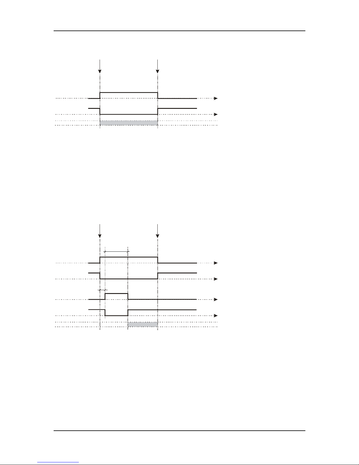
EAOM-210 FLJ.eng / ver 0.0
Pages 86 / 132
Example: If Hardware Breaker Selection parameter is selected as 0;
For closing
Gen. Shalter
Gen. Closed Out.
(NO)
Gen. Closed Out.
(NC)
For opening
Gen. Shalter
Closed
Gen. Shalter
Opened
t[s]
t[s]
1- Mains and Gen schalters have only close drives, when want to schalter close, close
breaker output on and after 1 sec. open breaker output on and after breaker close pulse time
open breaker output will off. When want to schalter open close breaker output and open
breaker output will off.
Parameters; GEN CLOSE BREAKER CONTACT TYPE, GEN CLOSE TIMER(if gen closed
input selected), GEN OPEN BREAKER CONTACT TYPE, GEN OPEN TIMER(if gen closed
input selected), MAIN CLOSE BREAKER CONTACT TYPE, MAINS CLOSE TIMER(if mains
closed input selected), MAIN OPEN BREAKER CONTACT TYPE, MAINS OPEN TIMER(if
mains closed input selected),BREAKER CLOSE PULSE TIME, TRANSFER TIME.
Example: If Hardware Breaker Selection parameter is selected as 1;
For closing
Gen. Shalter
Gen. Closed Out.
(NO)
Gen. Closed Out.
(NC)
For opening
Gen. Shalter
Closed
Gen. Shalter
Opened
t[s]
t[s]
t[s]
t[s]
Gen. Open Out.
(NO)
Gen. Open Out.
(NC)
1 s
Breaker close
pulse time
2- USER CONFIGURED: User can select all the schalter types.
Parameters; GEN CLOSE BREAKER CONTACT TYPE, GEN CLOSE BREAKER RELAY
TYPE, GEN CLOSE TIMER(if gen closed input selected), GEN OPEN BREAKER CONTACT
TYPE, GEN OPEN BREAKER RELAY TYPE, GEN OPEN TIMER(if gen closed input
selected), MAIN CLOSE BREAKER CONTACT TYPE, MAIN CLOSE BREAKER RELAY
TYPE, MAINS CLOSE TIMER(if mains closed input selected), MAIN OPEN BREAKER
CONTACT TYPE, MAIN OPEN BREAKER RELAY TYPE, MAINS OPEN TIMER(if mains
closed input selected), BREAKER CLOSE PULSE TIME(if Gen Close Breaker Relay Type or
Main Close Breaker Relay Type parameter is selected as 1), BREAKER OPEN PULSE
TIME(if Gen Open Breaker Relay Type or Main Open Breaker Relay Type parameter is
selected as 1), TRANSFER TIME.
Page 87
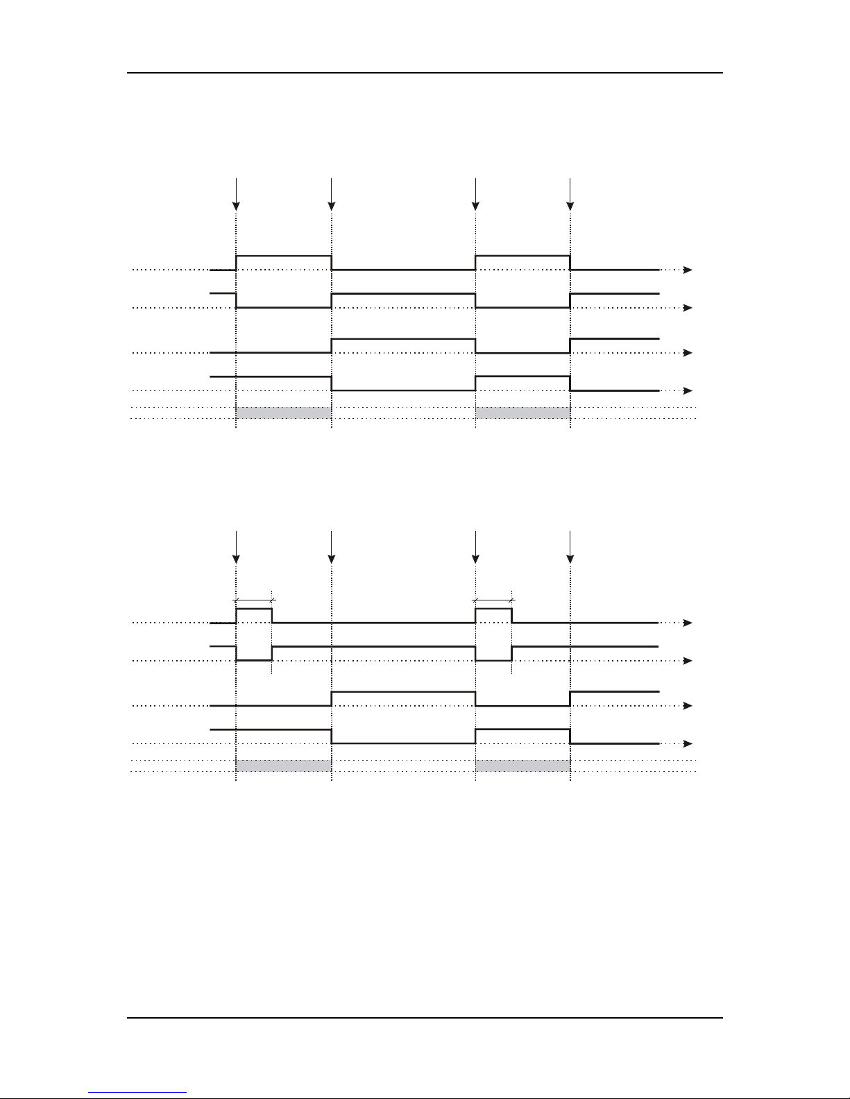
EAOM-210 FLJ.eng / ver 0.0
Pages 87 / 132
Example-1: If Hardware Breaker Selection parameter is selected as 2 (user configured),
Gen. Close Breaker Relay Type parameter is selected as 0 (NOR) and Gen. Open Breaker
Relay Type parameter is selected as 0 (NOR);
For closing
Gen. Shalter
Gen. Closed Out.
(NO)
Gen. Closed Out.
(NC)
For opening
Gen. Shalter
t[s]
t[s]
Closed
Gen. Shalter
Opened
For closing
Gen. Shalter
Gen. Open Out.
(NO)
Gen. Open Out.
(NC)
t[s]
t[s]
For opening
Gen. Shalter
Closed
Opened
Example-2: If Hardware Breaker Selection parameter is selected as 2 (user configured),
Gen. Close Breaker Relay Type parameter is selected as 1 (PULSE) and Gen. Open
Breaker Relay Type parameter is selected as 0 (NOR);
For closing
Gen. Shalter
Gen. Closed Out.
(NO)
Gen. Closed Out.
(NC)
For opening
Gen. Shalter
t[s]
t[s]
Closed
Gen. Shalter
Opened
For closing
Gen. Shalter
Gen. Open Out.
(NO)
Gen. Open Out.
(NC)
t[s]
t[s]
For opening
Gen. Shalter
Closed
Opened
Breaker close
pulse ti me
Breaker close
pulse ti me
Page 88
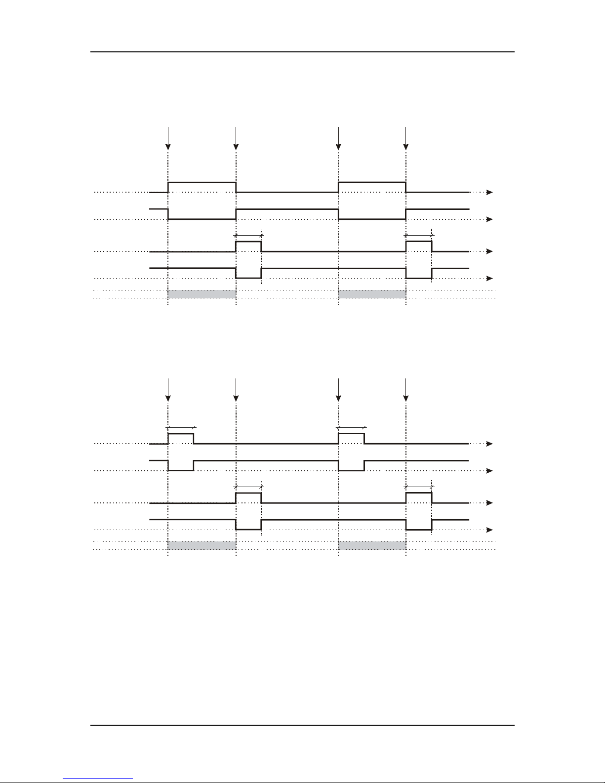
EAOM-210 FLJ.eng / ver 0.0
Pages 88 / 132
Example-3: If Hardware Breaker Selection parameter is selected as 2 (user configured),
Gen. Close Breaker Relay Type parameter is selected as 0 (NOR) and Gen. Open Breaker
Relay Type parameter is selected as 1 (PULSE);
For closing
Gen. Shalter
Gen. Closed Out.
(NO)
Gen. Closed Out.
(NC)
For opening
Gen. Shalter
t[s]
t[s]
Closed
Gen. Shalter
Opened
For closing
Gen. Shalter
Gen. Open Out.
(NO)
Gen. Open Out.
(NC)
t[s]
t[s]
For opening
Gen. Shalter
Closed
Opened
Breaker open
pulse ti me
Breaker o pen
pulse ti me
Example-4: If Hardware Breaker Selection parameter is selected as 2 (user configured),
Gen. Close Breaker Relay Type parameter is selected as 1 (PULSE) and Gen. Open
Breaker Relay Type parameter is selected as 1 (PULSE);
For closing
Gen. Shalter
Gen. Closed Out.
(NO)
Gen. Closed Out.
(NC)
For opening
Gen. Shalter
t[s]
t[s]
Closed
Gen. Shalter
Opened
For closing
Gen. Shalter
Gen. Open Out.
(NO)
Gen. Open Out.
(NC)
t[s]
t[s]
For opening
Gen. Shalter
Closed
Opened
Breaker open
pulse ti me
Breaker o pen
pulse ti me
Breaker close
pulse ti me
Breaker close
pulse ti me
GEN. CLOSE TIMER
This is used to monitor the closure of the generator contactor or breaker. It will only operate if
an auxiliary input is configured as ‘Generator Closed Auxiliary’ and connected to the auxiliary
on the generator contactor or breaker. Once a generator closed signal is issued the ‘gen
close timer’ is initiated. Should the ‘Generator Closed Auxiliary’ input become active the timer
the ‘gen close timer’ is cancelled. If the timer expires and the ‘Generator Closed Auxiliary’
has not become active the module will issue a ‘generator failed to close’ alarm.
GEN. OPEN TIMER
This is used to monitor the opening of the generator contactor or breaker. It will only operate
if an auxiliary input is configured as ‘Generator Closed Auxiliary’ and connected to the
auxiliary on the generator contactor or breaker. Once a generator open signal is issued the
Page 89

EAOM-210 FLJ.eng / ver 0.0
Pages 89 / 132
‘gen open timer’ is initiated. Should the ‘Generator Closed Auxiliary’ input become in-active
the timer ‘gen open timer’ is cancelled. If the timer expires and the ‘Generator Closed
Auxiliary’ has not become in-active the module will issue a ‘generator failed to open’ alarm.
MAINS CLOSE TIMER
This is used to monitor the closure of the mains contactor or breaker. It will only operate if an
auxiliary input is configured as ‘Mains Closed Auxiliary’ and connected to the auxiliary on the
mains contactor or breaker. Once a mains closed signal is issued the ‘mains close timer’ is
initiated. Should the ‘Mains Closed Auxiliary’ input become active the timer the ‘mains close
timer’ is cancelled. If the timer expires and the ‘Mains Closed Auxiliary’ has not become
active the module will issue a ‘mains failed to close’ alarm.
MAINS OPEN TIMER
This is used to monitor the opening of the mains contactor or breaker. It will only operate if
an auxiliary input is configured as ‘Mains Closed Auxiliary’ and connected to the auxiliary on
the mains contactor or breaker. Once a mains open signal is issued the ‘mains open timer’ is
initiated. Should the ‘Mains Closed Auxiliary’ input become in-active the timer the ‘mains
open timer’ is cancelled. If the timer expires and the ‘Mains closed auxiliary’ has not become
in-active the module will issue a ‘mains failed to open’ alarm.
BREAKER CLOSE PULSE TIME
This is used to determine the duration of the Mains and Generator close signals. This timer is
only used if Pulsed outputs are configured to be used.
BREAKER OPEN PULSE TIME
This is used to determine the duration of the Mains and Generator close signals. This timer is
only used if Pulsed outputs are configured to be used.
TRANSFER TIME
This is used to allow for fixed duration transfer breaks when switching from mains to
generator and back. It can be used to ensure that the supply is removed from the load for
fixed period of time to allow pumps/motors to come to rest etc.
(LCD CONFIG.PAGE) LCD CONFIGURATION page
ERR.MESS SCROLL TIM
Scroll Time For Error Messages Sec 1 - 99 2
DIGITAL CONTRAST
Digital Contrast 0 – 15 7
BACKLIGHT ON/OFF
Backlight On/Off 0 - 1 0
AUTO SCROLL TIMER
Error messages are displayed eighth line of LCD Display. If more than one error condition is
present, each of them is displayed during time defined by Auto Scroll Timer parameter.
DIGITAL CONTRAST
It is used to change contrast of LCD Display.
BACKLIGHT ON/OFF
0- Backlight on. 1- Backlight off.
Page 90
EAOM-210 FLJ.eng / ver 0.0
Pages 90 / 132
(ENG.MAINT.ALARM PAGE) ENGINE MAINTENANCE ALARM page
RUNN.HOURS INTERVAL Running Hours Interval
HOUR (dis)0 - 9999 5000
MAINT.DATE INTERVAL Maintenance Date Interval
MONTH (dis)0 - 12 6
ENG.STP.WH.MANT.E/D
Force Engine Shutdown When
Maintenance Is Due En/Dis
- ENAB DIS DIS
ENGIN.RUN.HOUR(LSB) Engine Running Hour (Lsb)
- 0 - 255 0
ENGINE RUNNING HOUR Engine Running Hour
- 0 – 255 0
ENGIN.RUN.HOUR(MSB) Engine Running Hour(Msb)
- 0 - 14 0
(COMMUNICATION PAGE) COMMUNICATION page
SLAVE ADDRESS Slave Address
1 - 247 1
BAUD RATE
Baud Rate
0=1200
1=2400
2=4800
3=9600
4=19200
0 - 4 3
PARITY Parity; 0= NONE, 1= ODD, 2= EVEN
0 - 2 0
STOP BIT Stop Bit
0 – 1 0
CALL BACK SELECTION
0 - Disabled
1 – With Ethernet
2 – With Modem
3 – With Ethernet and Modem
(dis)0 3 DIS
SMS ENABLE SMS enable or disable
ENAB/DIS DIS
Page 91

EAOM-210 FLJ.eng / ver 0.0
Pages 91 / 132
(CONFIG. LED-123 PAGE) LED-1,2,3 CONFIGURATION page
LED-1 FUNCTION
LED-1 function can be configurable to
simulate one of the conf. Inputs or error
messages:
0- Led not used
1- Conf. Input-1 error or status active
2- Conf. Input-2 error or status active
3- Conf. Input-3 error or status active
4- Conf. Input-4 error or status active
5- Conf. Input-5 error or status active
6- Conf. Input-6 error or status active
7- Exp. conf. Input-1 error or status active
8- Exp. conf. Input-2 error or status active
9- Exp. conf. Input-3 error or status active
10- Exp. conf. Input-4 error or status active
11- Exp. conf. Input-5 error or status active
12- Exp. conf. Input-6 error or status active
13- Exp. conf. Input-7 error or status active
14- Exp. conf. Input-8 error or status active
15- Emergency stop
16- Over speed error
17- Under speed error
18- Over speed prealarm
19- Under speed prealarm
20- Multiple engage fail
21- Speed loss error
22- Generator stop error
23- Level error
24- Battery low error
25- Battery high error
26- Temp prealarm
27- Level prealarm
28- Pressure prealarm
29- Generator Under Voltage prealarm
30- Generator Over Voltage prealarm
31- Generator Under Frequency prealarm
32- Generator Over Frequency prealarm
33- Maintenance error
34- Generator Breaker Not Closed alarm
35- Generator Breaker Not Opened alarm
36- Mains Breaker Not Closed alarm
37- Mains Breaker Not Opened alarm
38- Over Current Error
39- Short Circuit Error
40- Earth Fault Error
41- J1939 Amber warning lamp error
42- Over Current Warning
43- Short Circuit Warning
44- Earth Fault Warning
45- J1939 Red stop lamp error
46- Over Current Electrical Trip
47- Short Circuit Electrical Trip
48- Earth Fault Electrical Trip
49- Can Bus error
(dis)0 - 49 1
LED-2 FUNCTION Same as the LED-1 function
0 - 49 2
LED-3 FUNCTION Same as the LED-1 function
0 - 49 3
Page 92
EAOM-210 FLJ.eng / ver 0.0
Pages 92 / 132
(WR.CALENDR&EXER.PAGE) WORKING CALENDAR & EXERCISE page
WORK.PERIOD ON MON.
Working calendar working time on
Monday
min (dis)0 - 1440 1440
WORK.START TIME MON
Working calendar work start time on
Monday
hour-min 0.0 – 23.59 0.0
WORK.PERIOD ON TUE.
Working calendar working time on
Tuesday
min (dis)0 - 1440 1440
WORK.START TIME TUE
Working calendar work start time on
Tuesday
hour-min 0.0 – 23.59 0.0
WORK.PERIOD ON WED.
Working calendar working time on
Wednesday
min (dis)0 - 1440 1440
WORK.START TIME WED
Working calendar work start time on
Wednesday
hour-min 0.0 – 23.59 0.0
WORK.PERIOD ON THU.
Working calendar working time on
Thursday
min (dis)0 - 1440 1440
WORK.START TIME THU
Working calendar work start time on
Thursday
hour-min 0.0 – 23.59 0.0
WORK.PERIOD ON FRI. Working calendar working time on Friday
min (dis)0 - 1440 1440
WORK.START TIME FRI
Working calendar work start time on
Friday
hour-min 0.0 – 23.59 0.0
WORK.PERIOD ON SAT.
Working calendar working time on
Saturday
min (dis)0 - 1440 1440
WORK.START TIME SAT
Working calendar work start time on
Saturday
hour-min 0.0 – 23.59 0.0
WORK.PERIOD ON SUN. Working calendar working time on Sunday
min (dis)0 - 1440 1440
WORK.START TIME SUN
Working calendar work start time on
Sunday
Hour-min 0.0 – 23.59 0.0
EXER.WORKING PERIOD
Generator exercise working time on
related day
min (dis)0 - 99 DIS
EXER.WR.DAY OF WEEK Generator exercise working day of week
1 – 7 1
EXER.WORK.START TIM
Generator exercise work start time on
related day
hour-min 0.0 – 23.59 0.0
Please enter the days of the weekly workdays for Working Function. Example:
WORK.PERIOD ON MON. (dis)0 The working function is Mondays disabled.
(1440) The working function is enabled whole day.
(120) The working function is every Monday enabled for 120
minutes.
WORK.START TIME MON 12.20 The working function is every Monday started
at 12.20 o'clock (if it is enabled)
WORK.PERIOD ON TUE. (dis)0 The working function is Tuesdays disabled.
(1440) The working function is enabled whole day.
(120) The working function is every Tuesday enabled for 120
minutes.
WORK.START TIME TUE 12.20 The working function is every Tuesday started
at 12.20 o'clock (if it is enabled)
WORK.PERIOD ON WED. (dis)0 The working function is Wednesdays disabled.
(1440) The working function is enabled whole day.
(120) The working function is every Wednesday enabled for
120 minutes.
WORK.START TIME WED 12.20 The working function is every Wednesday started
at 12.20 o'clock (if it is enabled)
WORK.PERIOD ON THU. (dis)0 The working function is Thursdays disabled.
(1440) The working function is enabled whole day.
(120) The working function is every Thursday enabled for 120
minutes.
Page 93

EAOM-210 FLJ.eng / ver 0.0
Pages 93 / 132
WORK.START TIME THU 12.20 The working function is every Thursday started
at 12.20 o'clock (if it is enabled)
WORK.PERIOD ON FRI. (dis)0 The working function is Fridays disabled.
(1440) The working function is enabled whole day.
(120) The working function is every Friday enabled for 120
minutes.
WORK.START TIME FRI 12.20 The working function is every Friday started
at 12.20 o'clock (if it is enabled)
WORK.PERIOD ON SAT. (dis)0 The working function is Saturdays disabled.
(1440) The working function is enabled whole day.
(120) The working function is every Saturday enabled for 120
minutes.
WORK.START TIME SAT 12.20 The working function is every Saturday started
at 12.20 o'clock (If it is enabled)
WORK.PERIOD ON SUN. (dis)0 The working function is Sundays disabled.
(1440) The working function is enabled whole day.
(120) The working function is every Sunday enabled for 120
minutes.
WORK.START TIME SUN 12.20 The working function is every Sunday started
at 12.20 o'clock (If it is enabled)
Please enter the day of the week for Exercise Function. Example:
EXER.WORKING PERIOD (dis)0 The exercise function is disabled.
(10) The exercise function is enabled for 10 minutes.
EXER.WR.DAY OF WEEK 1=Monday, 2=Tuesday, 3=Wednesday, 4=Thursday,
5=Friday, 6=Saturday, 7=Sunday.
EXER.WORK.START TIM 12.20 The exercise function is started at 12.20 o'clock
(If it is enabled)
(DATE SETUP PAGE) DATE SETUP page
YEAR YEAR
0 - 99
MONTH MONTH
1 - 12
DATE DATE
1 - 31
DAY DAY
1 - 7
HOUR HOUR
0 - 23
MINUTE MIN
0 - 59
SECOND SEC
0 - 59
(PASSWORD PAGE) PASSWORD page
OPERATOR PASSWORD OPERATOR PASSWORD
0 - 9999 0
TECHNICIAN PASSWORD TECHNICIAN PASSWORD
0 - 9999 0
BACK FACTRY.DEFAULT Back Factory Default
No/Yes No
OPERATOR PASSWORD
Use this option to change the Operator password. This password allows access to operator
parameters section.
TECHNICIAN PASSWORD
Use this option to change the Technician password. It allows access to both operator and
technician parameters section.
BACK FACTORY DEFAULT
If this parameter is selected as “Yes”, the unit’s parameters back to factory defaults. After
this parameter is reset automatically to “No”.
Page 94
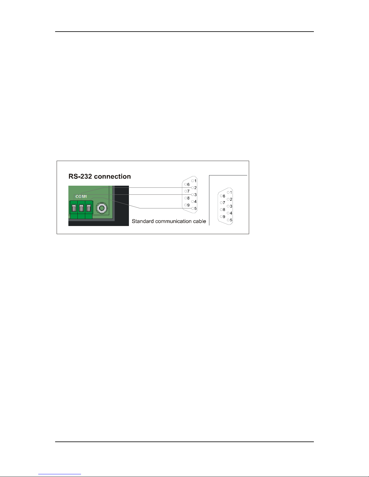
EAOM-210 FLJ.eng / ver 0.0
Pages 94 / 132
3.6 Pc Interface
The PC interface kit (PCIK) comprises the following:
9 pin D connector/FCC68(4 pin) connection lead with 2 meters cable
EAOM-210 FLJ configuration software (CD)
3.6.1 Technical Specifications
RS-232 serial communication with Modbus ASCII protocol
Baud Rate from 1200 to 19200
8 data bits, Parity; None, Odd or Even, Stop Bit; 0 or 1
Maximum allowable cable length is 10 meters
3.6.2 RS-232 Serial Interface, Programming The Device Over PC or Modem
3.6.2.1 Cable Connection Between RS-232 Terminal of the Device and PC
9 pin D connector
female
PC
9 pin D connector
male
RX TX GND
3.6.3 Installation Instruction
3.6.3.1 Minimum system requirements
Processor :486 66MHz
Operating Systems :Windows95/98, Windows NT
Ram :16 Mbyte
Monitor :14” SVGA (640x480 resolution)
Fixed Disk Free Space :1 Mbyte
Disk Drive :CD-ROM
Communication :An RS232 communication port is needed to
communicate with the EAOM-210 FLJ Unit
3.6.3.2 Installing EAOM-210 FLJ configuration software
Insert the software CD into the CD-ROM drive on the PC
Double click on MyComputer
Then double click on CD-ROM drive
There will be a short delay while the CD-ROM is accessed, then the disk contents will be
displayed.
Double click on “Install.exe”.
EAOM-210 FLJ configuration software will be installed automatically on to your PC in its
own folder(directory). It will also create “START MENU” items.
Page 95
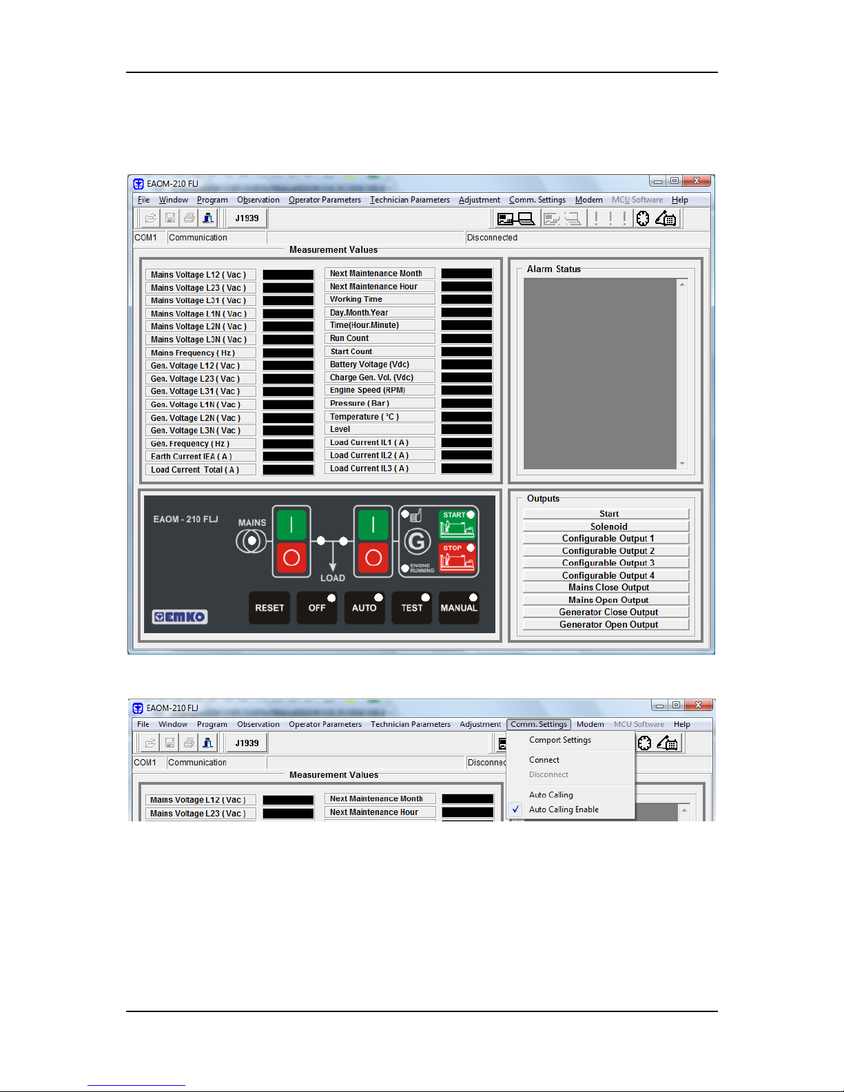
EAOM-210 FLJ.eng / ver 0.0
Pages 95 / 132
3.6.3.3 To Run EAOM-210 FLJ configuration software
Press the START icon
Then select Programs EAOM-210 FLJ PC SW(Folder) EAOM-210 FLJ V00.00
Then click on EAOM-210 FLJ configuration software. The below screen is shown.
Click “Connect” in Comm. Settings menu.
The “Connection and Device Location Settings” window is shown.
Page 96
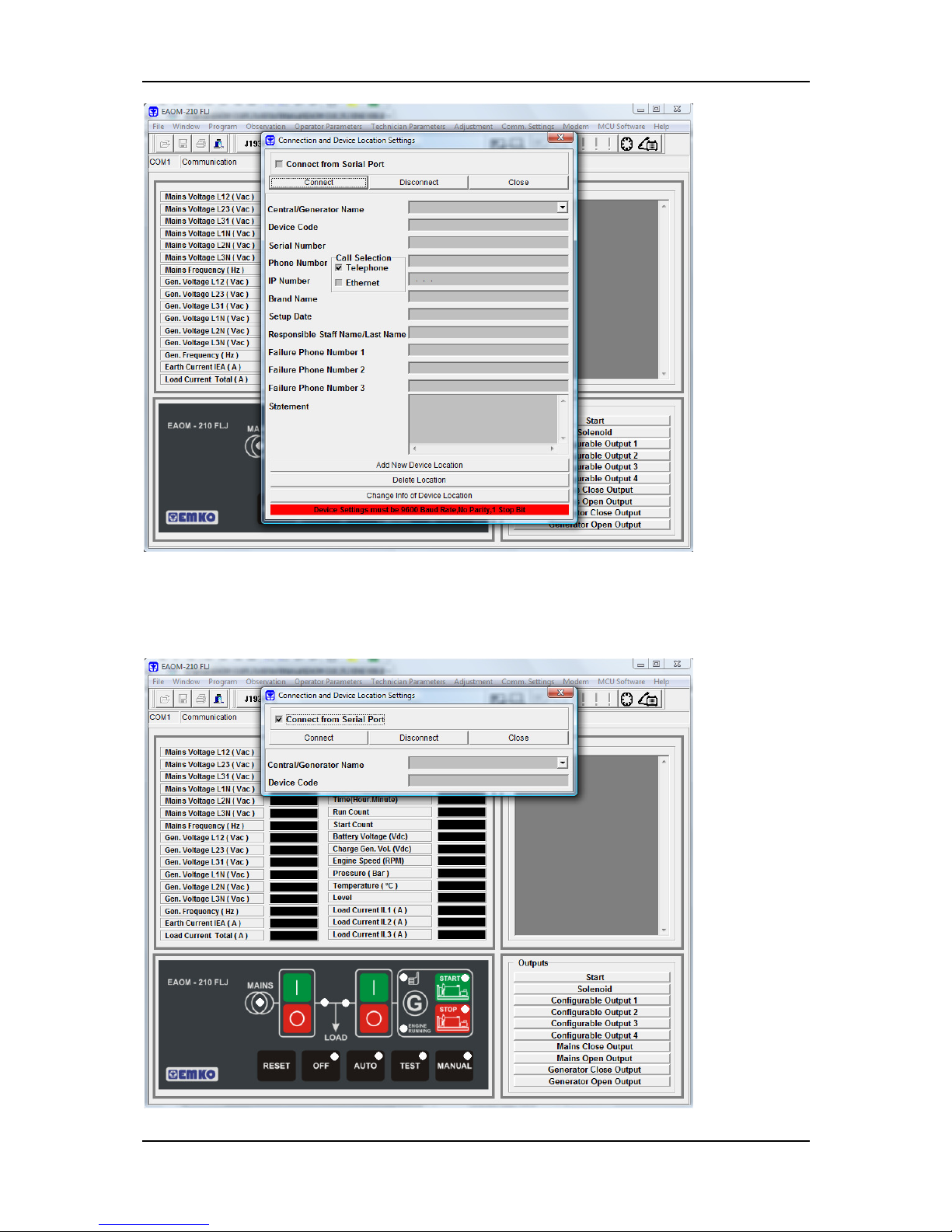
EAOM-210 FLJ.eng / ver 0.0
Pages 96 / 132
Now, you must to determine how the connection will be established: RS-232
communication port or Ethernet module / Dial-up or GSM modem. The RS-232 selection is
made with the ‘Connect from Serial port’ check box. When the serial port selection is
done, below screen is shown.
Page 97
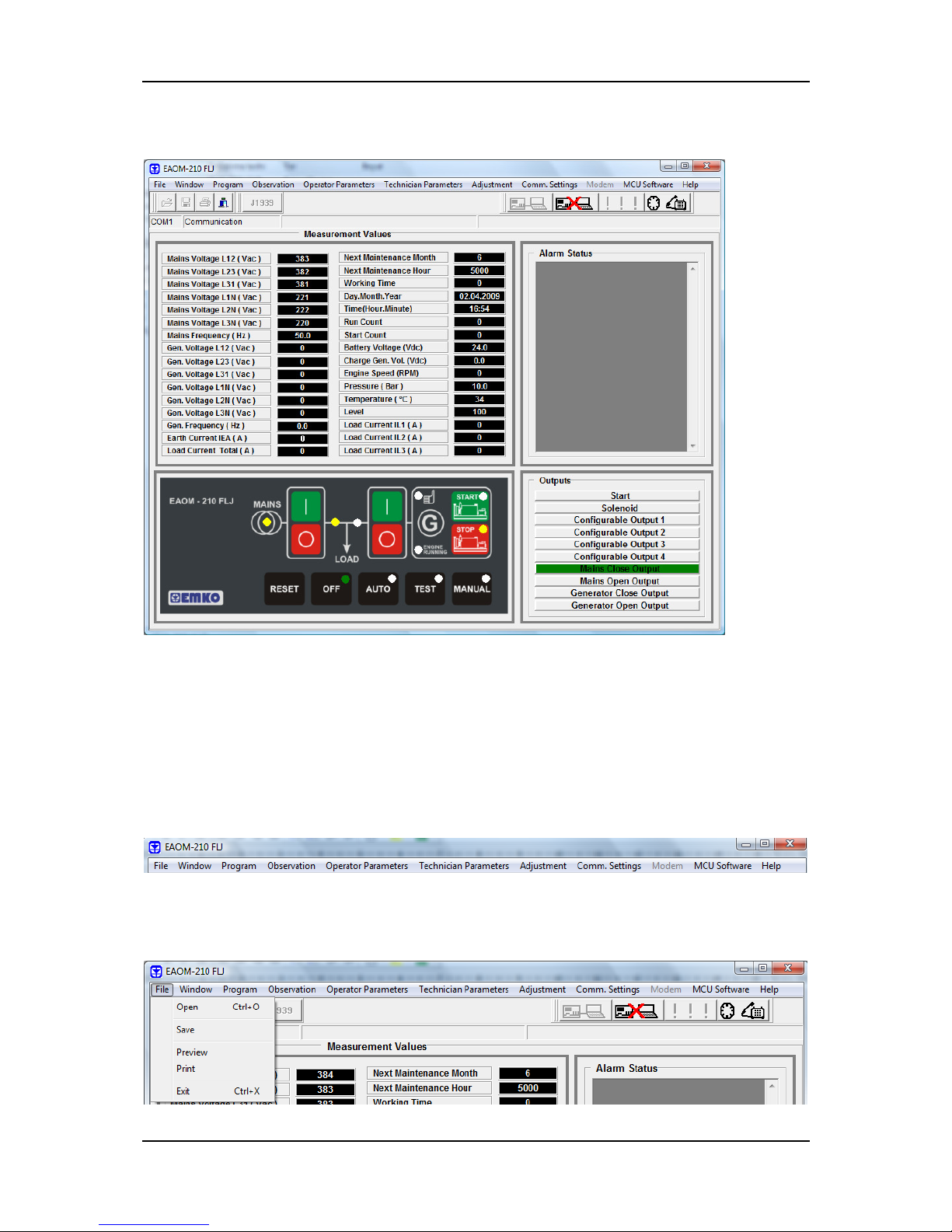
EAOM-210 FLJ.eng / ver 0.0
Pages 97 / 132
When the connection is established, main screen is shown;
3.6.4 Description
The EAOM-210 FLJ unit communicates with PC by means of EAOM-210 FLJ PCIK. With
EAOM-210 FLJ configuration software, the EAOM-210 FLJ unit’s parameters and status
information can be reached over PC easily. Operator and Technician parameters can be
viewed. It also allows download to device the ‘Serial / Phone Numbers’ and ‘Modem
Commands’ parameters. The all messages on the unit can be modified with this software.
Parameters are password protected.
3.6.4.1 Main Menu
File Menu
This menu allows the user to save configuration files to the disc, read from disc and write
to disc.
Page 98
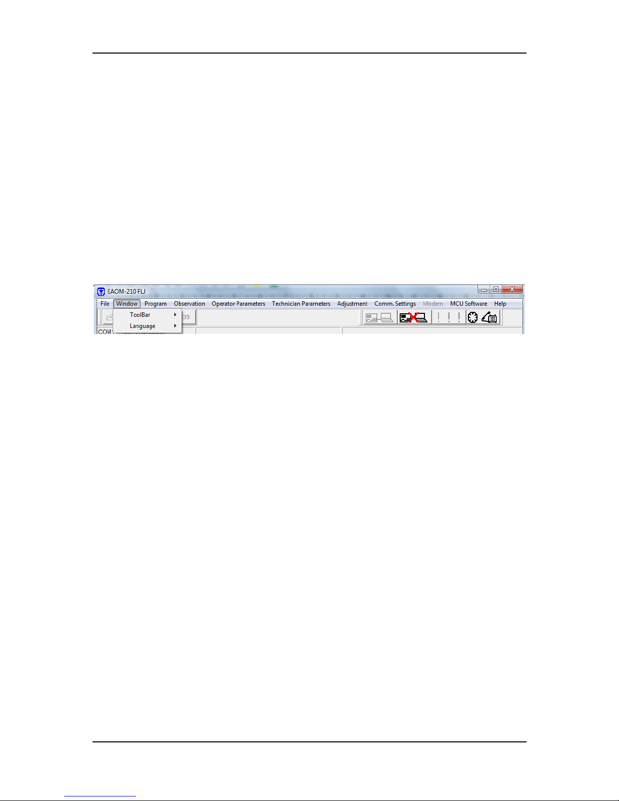
EAOM-210 FLJ.eng / ver 0.0
Pages 98 / 132
Open :This menu allows the user to load the registered configuration files to PC.
For example: Click 'Open' in File menu. Choose configuration file which includes operator
or technician parameters on Open Dialog Box. When user clicks 'Open' button on Open
Dialog Box parameters will be transferred to PC window.
Save :This menu allows the user to save the parameters with a name defined by user.
For example: Click 'Save' in File menu. After choosing where to save the file, enter the file
name. When user clicks 'Save' button on Save Dialog Box, all parameters will be saved to
the file that user determine.
Preview : This menu allows the user to preview the operator parameters, when the user to
come into the Operator Parameters section. It allows the user to preview the tech
nician
parameters, when the user to come into the Technician Parameters section. It allows the
user to preview the Event Logs, when the user to come into the Events section.
Print :This menu allows the user to print the parameters.
Exit :With this menu user can exit from the EAOM-210 FLJ configuration software.
Window Menu
Toolbar: Toolbar on/off
Language: This menu allows the user to choose language English or Turkish.
Program Menu
This menu allows load from EAOM-210 FLJ unit to PC or from PC to EAOM-210 FLJ unit the
parameters which used for data communication and SMS.
Configure Device Code & Connection Numbers & Modem Commands:
User can download or upload these parameters;
- Serial Number (Gen-set name)
- Device Code
- Failure Phone Number 1 (Phone number where active call will be done when the
alarm occurs on the unit)
- Failure Phone Number 2 (Phone number where active call will be done when the
alarm occurs on the unit)
- Failure IP No 1 (IP address where active call will be done when the alarm occurs
on the unit)
- Failure Port No 1 (Ethernet port where active call will be done when the alarm
occurs on the unit). Note: The value of this parameter must be the same as the
‘Port No’ in the Comm. Settings menu on the PC software.
- Failure IP No 2 (IP address where active call will be done when the alarm occurs
on the unit)
- Failure Port No 2 (Ethernet port where active call will be done when the alarm
occurs on the unit). Note: The value of this parameter must be the same as the
‘Port No’ in the Comm. Settings menu on the PC software.
- Responsible Staff’s SMS Number for Failure Notifications (Mobile number where
active SMS will be sent)
Page 99

EAOM-210 FLJ.eng / ver 0.0
Pages 99 / 132
Observation Menu
There are four sub-menus in this menu: Measurement Values, Power & Energy, Events and
Archive.
Measurement Values:
In this window the values listed below can be observed:
Mains volts (L1-N, L2-N, L3-N)
Mains volts (L1-L2, L2-L3, L3-L1)
Mains Hz
Generator volts (L1-N, L2-N, L3-N)
Generator volts (L1-L2, L2-L3, L3-L1)
Generator Hz
Earth current (IEA)
Load current total (IT)
Next maintenance
Working time
Real time
Run count
Start count
Battery Voltage
Charge generator voltage
Page 100
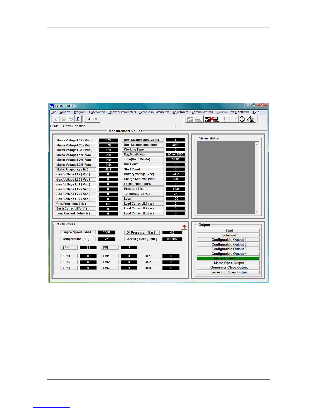
EAOM-210 FLJ.eng / ver 0.0
Pages 100 / 132
Engine speed (Rpm)
Pressure
Temperature
Level
Load current (IL1, IL2, IL3)
In this window, you can also observe the output status, alarm status and change mode,
start, stop, failure reset etc.
For the monitoring the J1939 ECU messages, please click the “J1939” button and the below
screen is shown.
 Loading...