

Page 1

Instruction Manual
CI-ControlWave EFM
Oct., 2006
ControlWave EFM
(Electronic Flow Meter)
ontrolWave EFM
www.EmersonProcess.com/Bristol
Page 2

IMPORTANT! READ INSTRUCTIONS BEFORE STARTING!
Be sure that these instructions are carefully read and understood before any
operation is attempted. Improper use of this device in some applications may result in
damage or injury. The user is urged to keep this book filed in a convenient location for
future reference.
These instructions may not cover all details or variations in equipment or cover
every possible situation to be met in connection with installation, operation or maintenance. Should problems arise that are not covered sufficiently in the text, the purchaser is advised to contact Bristol for further information.
EQUIPMENT APPLICATION WARNING
The customer should note that a failure of this instrument or system, for
whatever reason, may leave an operating process without protection. Depending upon
the application, this could result in possible damage to property or injury to persons.
It is suggested that the purchaser review the need for additional backup equipment
or provide alternate means of protection such as alarm devices, output limiting, failsafe valves, relief valves, emergency shutoffs, emergency switches, etc. If additional
in-formation is required, the purchaser is advised to contact Bristol .
RETURNED EQUIPMENT WARNING
When returning any equipment to Bristol for repairs or evaluation, please note
the following: The party sending such materials is responsible to ensure that the
materials returned to Bristol are clean to safe levels, as such levels are defined and/or
determined by applicable federal, state and/or local law regulations or codes. Such
party agrees to indemnify Bristol and save Bristol harmless from any liability or
damage which Bristol may incur or suffer due to such party's failure to so act.
ELECTRICAL GROUNDING
Metal enclosures and exposed metal parts of electrical instruments must be
grounded in accordance with OSHA rules and regulations pertaining to "Design
Safety Standards for Electrical Systems," 29 CFR, Part 1910, Subpart S, dated: April
16, 1981 (OSHA rulings are in agreement with the National Electrical Code).
The grounding requirement is also applicable to mechanical or pneumatic instruments that include electrically-operated devices such as lights, switches, relays,
alarms, or chart drives.
EQUIPMENT DAMAGE FROM ELECTROSTATIC DISCHARGE VOLTAGE
This product contains sensitive electronic components that can be damaged by
exposure to an electrostatic discharge (ESD) voltage. Depending on the magnitude
and duration of the ESD, this can result in erratic operation or complete failure of the
equipment. Read supplemental document S14006 at the back of this manual for
proper care and handling of ESD-sensitive components.
Bristol 1100 Buckingham Street, Watertown, CT 06795
Telephone (860) 945-2200
Page 3

WARRANTY
A. Bristol warrants that goods described herein and manufactured by Bristol are free
from defects in material and workmanship for one year from the date of shipment
unless otherwise agreed to by Bristol in writing.
B. Bristol warrants that goods repaired by it pursuant to the warranty are free from
defects in material and workmanship for a period to the end of the original warranty
or ninety (90) days from the date of delivery of repaired goods, whichever is longer.
C. Warranties on goods sold by, but not manufactured by Bristol, are expressly limited
to the terms of the warranties given by the manufacturer of such goods.
D. All warranties are terminated in the event that the goods or systems or any part
thereof are (i) misused, abused or otherwise damaged, (ii) repaired, altered or
modified without Bristol's consent, (iii) not installed, maintained and operated in
strict compliance with instructions furnished by Bristol, or (iv) worn, injured or
damaged from abnormal or abusive use in service time.
E. THESE WARRANTIES ARE EXPRESSLY IN LIEU OF ALL OTHER
WARRANTIES EXPRESS OR IMPLIED (INCLUDING WITHOUT LIMITATION
WARRANTIES AS TO MERCHANTABILITY AND FITNESS FOR A PARTICULAR
PURPOSE), AND NO WARRANTIES, EXPRESS OR IMPLIED, NOR ANY
REPRESENTATIONS, PROMISES, OR STATEMENTS HAVE BEEN MADE BY
BRISTOL UNLESS ENDORSED HEREIN IN WRITING. FURTHER, THERE ARE
NO WARRANTIES WHICH EXTEND BEYOND THE DESCRIPTION OF THE
FACE HEREOF.
F. No agent of Bristol is authorized to assume any liability for it or to make any written
or oral warranties beyond those set forth herein.
A. Buyer's sole remedy for breach of any warranty is limited exclusively to repair or
replacement without cost to Buyer of any goods or parts found by Seller to be
defective if Buyer notifies Bristol in writing of the alleged defect within ten (10) days
of discovery of the alleged defect and within the warranty period stated above, and if
the Buyer returns such goods to Bristol's Watertown office, unless Bristol's Watertown office designates a different location, transportation prepaid, within thirty (30)
days of the sending of such notification and which upon examination by Bristol
proves to be defective in material and workmanship. Bristol is not responsible for
any costs of removal, dismantling or reinstallation of allegedly defective or defective
goods. If a Buyer does not wish to ship the product back to Bristol, the Buyer can
arrange to have a Bristol service person come to the site. The Service person's
transportation time and expenses will be for the account of the Buyer. However,
labor for warranty work during normal working hours is not chargeable.
B. Under no circumstances will Bristol be liable for incidental or consequential
damages resulting from breach of any agreement relating to items included in this
quotation, from use of the information herein or from the purchase or use by Buyer,
its em-ployees or other parties of goods sold under said agreement.
REMEDIES
Page 4

How to return material for Repair or Exchange
Before a product can be returned to Bristol for repair, upgrade, exchange, or to verify
proper operation, form (GBU 13.01) must be completed in order to obtain a RA (Return
Authorization) number and thus ensure an optimal lead time. Completing the form is very
important since the information permits the Bristol Repair Dept. to effectively and
efficiently process the repair order.
You can easily obtain a RA number by:
A. FAX
Completing the form (GBU 13.01) and faxing it to (860) 945-3875. A Bristol Repair
Dept. representative will return call (or other requested method) with a RA number.
B. E-MAIL
Accessing the form (GBU 13.01) via the Bristol Web site (www.bristolbabcock.com)
and sending it via E-Mail to brepair@bristolbabcock.com
representative will return E-Mail (or other requested method) with a RA number.
C. Mail
Mail the form (GBU 13.01) to
Bristol Inc.
Repair Dept.
1100 Buckingham Street
Watertown, CT 06795
A Bristol Repair Dept. representative will return call (or other requested method)
with a RA number.
D. Phone
Calling the Bristol Repair Department at (860) 945-2442. A Bristol Repair Depart-
ment representative will record a RA number on the form and complete Part I, then
send the form to the Customer via fax (or other requested method) for Customer
completion of Parts II & III.
A copy of the completed Repair Authorization Form with issued RA number should be included with the product being returned. This will allow us to quickly track, repair, and
return your product to you.
. A Bristol Repair Dept.
Page 5

Bristol Inc. Repair Authorization Form (off-line completion)
(Providing this information will permit Bristol Inc. to effectively and efficiently process your return. Completion is required
to receive optimal lead time. Lack of information may result in increased lead times.)
Date___________________ RA #___________________SH_ Line No.____________
Standard Repair Practice is as follows: Variations to this is
practice may be requested in the “Special Requests” section.
• Evaluate / Test / Verify Discrepancy
• Repair / Replace / etc. in accordance with this form
• Return to Customer
Part I Please complete the following information for single unit or multiple unit returns
Address No. (office use only) Address No. (office use only)
Bill to : Ship to:
Purchase Order: Contact Name:____________________________________
Phone: Fax: E-Mail:
Part II Please complete Parts II & III for each unit returned
Model No./Part No. Description
Please be aware of the Non warranty standard charge:
• There is a $100 minimum evaluation charge, which is
applied to the repair if applicable (√ in “returned”
B,C, or D of part III below)
Range/Calibration S/N
Reason for return
: Failure Upgrade Verify Operation Other
1. Describe the conditions of the failure (Frequency/Intermittent, Physical Damage, Environmental Conditions,
Communication, CPU watchdog, etc.)
(Attach a separate sheet if necessary)
2. Comm. interface used: Standalone RS-485 Ethernet Modem (PLM (2W or 4W) or SNW) Other:______________
3. What is the Firmware revision? _____________________ What is the Software &version?
Part III If checking “replaced” for any question below, check an alternate option if replacement is not available
A. If product is within the warranty time period but is excluded due
to Bristol’s warranty clause, would you like the product:
repaired returned replaced scrapped?
B. If product were found to exceed the warranty period,
would you like the product:
C. If product is deemed not repairable would you like your product:
D. If Bristol is unable to verify the discrepancy, would you like the product:
repaired returned replaced scrapped?
returned replaced scrapped?
returned replaced *see below?
* Continue investigating by contacting the customer to learn more about the problem experienced? The person to contact
that has the most knowledge of the problem is: ______________________________ phone_____________________
If we are unable to contact this person the backup person is: _________________________
Special Requests: ____________________________________________________________________________________
phone_____________________
____________________________________________________________________________________________________
Ship prepaid to: Bristol Inc., Repair Dept., 1100 Buckingham Street, Watertown, CT 06795
Phone: 860-945-2442 Fax: 860-945-3875 Form GBU 13.01 Rev. B 04/11/06
Page 6
Bristol
Training
GET THE MOST FROM YOUR BRISTOL
BABCOCK INSTRUMENT OR SYSTEM
• Avoid Delays and problems in getting your system on-line
• Minimize installation, start-up and maintenance costs.
• Make the most effective use of our hardware and software.
• Know your system.
As you know, a well-trained staff is essential to your operation. Bristol Inc. offers a full
schedule of classes conducted by full-time, professional instructors. Classes are offered
throughout the year at three locations: Houston, Orlando and our Watertown, CT
headquarters. By participating in our training, your personnel can learn how to install,
calibrate, configure, program and maintain any and all Bristol products and realize the full
potential of your system.
For information or to enroll in any class, contact our training department in Watertown at
(860) 945-2343. For Houston classes, you can also contact our Houston office, at (713) 685-
6200.
Page 7

A Few Words About Bristol Inc.
For over 100 years, Bristol® has been providing innovative solutions for the measurement
and control industry. Our product lines range from simple analog chart recorders, to
sophisticated digital remote process controllers and flow computers, all the way to turnkey
SCADA systems. Over the years, we have become a leading supplier to the electronic gas
measurement, water purification, and wastewater treatment industries.
On off-shore oil platforms, on natural gas pipelines, and maybe even at your local water
company, there are Bristol Inc. instruments, controllers, and systems running year-in and
year-out to provide accurate and timely data to our customers.
Getting Additional Information
In addition to the information contained in this manual, you may receive additional assistance in using this product from the following sources:
Help Files / Release Notes
Many Bristol software products incorporate help screens. In addition, the software typically
includes a ‘read me’ release notes file detailing new features in the product, as well as other
information which was available too late for inclusion in the manual.
Contacting Bristol Inc. Directly
Bristol's world headquarters is located at 1100 Buckingham Street, Watertown,
Connecticut 06795, U.S.A.
Our main phone numbers are:
(860) 945-2200
(860) 945-2213 (FAX)
Regular office hours are Monday through Friday, 8:00AM to 4:30PM Eastern Time,
excluding holidays and scheduled factory shutdowns. During other hours, callers may leave
messages using Bristol's voice mail system.
Telephone Support - Technical Questions
During regular business hours, Bristol's Application Support Group can provide telephone
support for your technical questions.
For technical questions about TeleFlow products call (860) 945-8604.
For technical questions about ControlWave call (860) 945-2394 or (860) 945-2286.
For technical questions regarding Bristol’s OpenEnterprise product, call (860) 945-3865
or e-mail: scada@bristolbabcock.com
Page 8

For technical questions regarding ACCOL products, OpenBSI Utilities, UOI and all other
software except for ControlWave and OpenEnterprise products, call (860) 945-2286.
For technical questions about Network 3000 hardware, call (860) 945-2502.
You can e-mail the Application Support Group at: bsupport@bristolbabcock.com
The Application Support Group maintains an area on our web site for software updates and
technical information. Go to: www.bristolbabcock.com/services/techsupport/
For assistance in interfacing Bristol hardware to radios, contact Bristol’s Communication
Technology Group in Orlando, FL at (407) 629-9463 or (407) 629-9464.
You can e-mail the Communication Technology Group at:
orlandoRFgroup@bristolbabcock.com
Telephone Support - Non-Technical Questions, Product Orders, etc.
Questions of a non-technical nature (product orders, literature requests, price and delivery
information, etc.) should be directed to the nearest sales office (listed on the rear cover of
this manual) or to your Bristol-authorized sales representative.
Please call the main Bristol Inc. number (860-945-2200) if you are unsure which office
covers your particular area.
Visit our Site on the World Wide Web
For general information about Bristol Inc. and its products, please visit our site on the
World Wide Web at: www.bristolbabcock.com
Training Courses
Bristol’s Training Department offers a wide variety of courses in Bristol hardware and
software at our Watertown, Connecticut headquarters, and at selected Bristol regional
offices, throughout the year. Contact our Training Department at (860) 945-2343 for course
information, enrollment, pricing, and scheduling.
Page 9

CI-ControlWave EFM
ControlWave EFM
Electronic Flow Meter
INSTALLATION FORWARD
NOTE for all ControlWave EFM Installers:
READ THIS SECTION FIRST!
This manual has been designed for the following audience:
• Customer Site Engineers, who must plan for the installation and implementation of the
ControlWave EFM.
• Instructors who must become familiar with and teach Field Engineers/Technicians on
the installation, operation and repair of ControlWave EFM.
• Field Engineers/Technicians who must install and service the ControlWave EFM.
Installation of the ControlWave EFM electronic flow meter is provided in two formats as
follows:
Section 2 - Installation & Operation
operation of the ControlWave EFM. Section 2 provides all the information required for
instructors who are training individuals unfamiliar with the ControlWave EFM. It is also
intended to support anyone who needs to learn how to install and operate the
ControlWave EFM for the first time.
Appendix C - Hardware Installation Guide
familiar with the ControlWave EFM but need the configuration information in a concise
format. Field Engineers/Technicians who have previously installed one or more
ControlWave EFM electronic flow meters will find the necessary installation information
logically sequenced for their convenience.
A Windows driven diagnostic tool referred to as WINDIAG is provided on the
OpenBSI Software CDROM. WINDIAG is documented in instruction manual
D4041A – Window Diagnostics for Bristol Controllers
provides menu driven diagnostics that have been designed to assist a technician
or Process Engineer in troubleshooting the various ControlWave EFM circuits. A
brief overview is provided in Section 3.5 of this manual. For more detailed
descriptions of ControlWave EFM Windows Diagnostics than those provided
herein, see Document D4041A – Chapters 1 and 7B.
provides a detailed overview of the installation and
is intended for individuals who are already
NOTE:
. Bristol’s WINDIAG program
CI-ControlWave EFM - Installation Forward
Page 10

CI-ControlWave EFM
ControlWave EFM
Electronic Flow Meter
TABLE OF CONTENTS
SECTION TITLE PAGE #
Section 1 - ControlWave EFM INTRODUCTION
1.1 GENERAL DESCRIPTION ........................................................................................... 1-1
1.2 ControlWave PROGRAMMING ENVIRONMENT ....................................................1-5
1.3 PHYSICAL DESCRIPTION........................................................................................... 1-7
1.3.1 Enclosure......................................................................................................................... 1-8
1.3.2 CPU Module .................................................................................................................... 1-8
1.3.2.1 CPU Module Connectors .............................................................................................. 1-10
1.3.2.2 CPU Memory................................................................................................................. 1-10
1.3.2.3 CPU Module Configuration Jumpers .......................................................................... 1-11
1.3.2.4 CPU Module Configuration Switches.......................................................................... 1-11
1.3.2.5 CPU Module LEDs ....................................................................................................... 1-12
1.3.3 System Controller Module (SCM) ................................................................................ 1-12
1.3.3.1 SCM Mode Switch.........................................................................................................1-13
1.3.3.2 SCM Board Fuse........................................................................................................... 1-13
1.3.3.3 SCM Board Connectors ................................................................................................ 1-14
1.3.3.4 SCM Jumpers ............................................................................................................... 1-14
1.3.3.5 SCM LEDs.....................................................................................................................1-14
1.3.4 ControlWave EFM Backplanes.................................................................................. 1-14
1.3.5 ControlWave EFM Base Assembly Chassis.............................................................. 1-15
1.3.6 ControlWave EFM I/O Modules ................................................................................ 1-16
1.3.6.1 Non-isolated Analog I/O & Analog Input Modules ..................................................... 1-17
1.3.6.2 Non-isolated Digital Input/Output Module................................................................. 1-17
1.3.6.3 Non-isolated High Speed Counter Input Module........................................................ 1-17
1.3.6.4 Non-isolated Mixed Input/Output Module .................................................................. 1-17
1.3.7 ControlWave EFM Expansion Communications Modules ....................................... 1-17
1.3.8 Internal Mounting Brackets ........................................................................................ 1-18
1.3.9 Multivariable Transducer ............................................................................................1-19
1.3.10 Power Distribution Board ............................................................................................ 1-19
1.3.11 Digital to Relay I/O Option .......................................................................................... 1-19
1.3.12 21V Power Supply Option ............................................................................................1-20
1.3.13 Power System................................................................................................................ 1-20
1.3.14 RTD Probe..................................................................................................................... 1-21
1.3.15 External Radio/Modem................................................................................................. 1-21
1.4 FIELD WIRING............................................................................................................1-21
1.5 FUNCTIONS................................................................................................................. 1-21
1.5.1 Data Acquisition ........................................................................................................... 1-22
1.5.2 Flow and Volume Calculations ....................................................................................1-22
1.5.2.1 Flow Rate and Flow Time Calculations (AGA3) ......................................................... 1-23
1.5.2.2 Flow Rate Calculations and Flow Time Accumulations (AGA7) ...............................1-23
1.5.2.3 Extension Calculation and Analog Averaging ............................................................1-23
1.5.2.3.1 Energy Calculation ....................................................................................................... 1-23
1.5.2.3.2 Volume and Energy Integration ..................................................................................1-23
1.5.2.4 Downstream Pressure Tap........................................................................................... 1-23
1.5.3 Archives.........................................................................................................................1-24
1.5.3.1 Hourly Historical Data Log.......................................................................................... 1-24
CI-ControlWave EFM Contents / 0 - 1
Page 11

CI-ControlWave EFM
ControlWave EFM
Electronic Flow Meter
TABLE OF CONTENTS
SECTION TITLE PAGE #
Section 1 - ControlWave EFM INTRODUCTION (Continued)
1.5.3.2 Daily Historical Data Log ............................................................................................1-24
1.5.3.3 Periodic Historical Data Log........................................................................................ 1-25
1.5.3.4 Alarm and Event Storage............................................................................................. 1-25
1.5.4 LCD Display..................................................................................................................1-25
1.5.5 Communications ........................................................................................................... 1-26
1.5.5.1 BSAP Message Support................................................................................................ 1-27
1.5.6 Discrete and Analog I/O EFM Functionality .............................................................. 1-27
1.5.6.1 Flow Rate Control - DDC (jog control) using PID....................................................... 1-27
1.5.6.2 Pulse Output for External Totalizer or Sampler ........................................................ 1-28
1.5.6.3 Nominations..................................................................................................................1-28
1.5.7 Self Test & Diagnostics ................................................................................................1-28
Section 1A - PRODUCT FEATURES & OVERVIEW
1A.1 PRODUCT OVERVIEW.............................................................................................. 1A-1
1A.1.1 Hardware Features......................................................................................................1A-1
1A.1.2 Firmware and Software Features............................................................................... 1A-1
1A.2 PRODUCT FAMILY COMPATIBILITY .................................................................... 1A-2
1A.2.1 Open Standards for Programming, Network Config. and Communication ............. 1A-2
1A.2.2 ControlWave Designer with ACCOL III................................................................... 1A-2
1A.2.3 ACCOL III.................................................................................................................... 1A-2
1A.3 STANDARD APPLICATION PROGRAM.................................................................. 1A-3
1A.3.1 OpenBSI - Simply Creative......................................................................................... 1A-3
1A.3.2 OpenBSI Utilities ........................................................................................................ 1A-4
1A.3.3 Real-time ActiveX Controls......................................................................................... 1A-4
1A.3.3.1 ActiveX Controls .......................................................................................................... 1A-5
1A.3.3.2 Required Software ....................................................................................................... 1A-5
1A.3.4 Historical Data Collection ........................................................................................... 1A-5
1A.3.5 OPC Server .................................................................................................................. 1A-5
1A.4 ControlWave OPEN NETWORK CONNECTIVITY................................................ 1A-6
1A.4.1 Communication Protocols............................................................................................ 1A-6
1A.4.1.1 BSAP Protocol .............................................................................................................. 1A-6
1A.4.1.2 Modbus Protocol........................................................................................................... 1A-7
1A.4.1.3 Generic Serial Interface ..............................................................................................1A-7
Section 2 - INSTALLATION & OPERATION
2.1 INSTALLATION IN HAZARDOUS AREAS................................................................. 2-1
2.2 SITE LOCATION CONSIDERATIONS........................................................................ 2-4
2.2.1 Temperature & Humidity Limits .................................................................................. 2-4
2.2.2 Vibration Limits ............................................................................................................. 2-4
2.3 ControlWave EFM INSTALLATION/CONFIGURATION ........................................ 2-4
2.3.1 Mounting the ControlWave EFM Enclosure ..............................................................2-8
0 - 2 / Contents CI-ControlWave EFM
Page 12

CI-ControlWave EFM
ControlWave EFM
Electronic Flow Meter
TABLE OF CONTENTS
SECTION TITLE PAGE #
Section 2 - INSTALLATION & OPERATION (Continued)
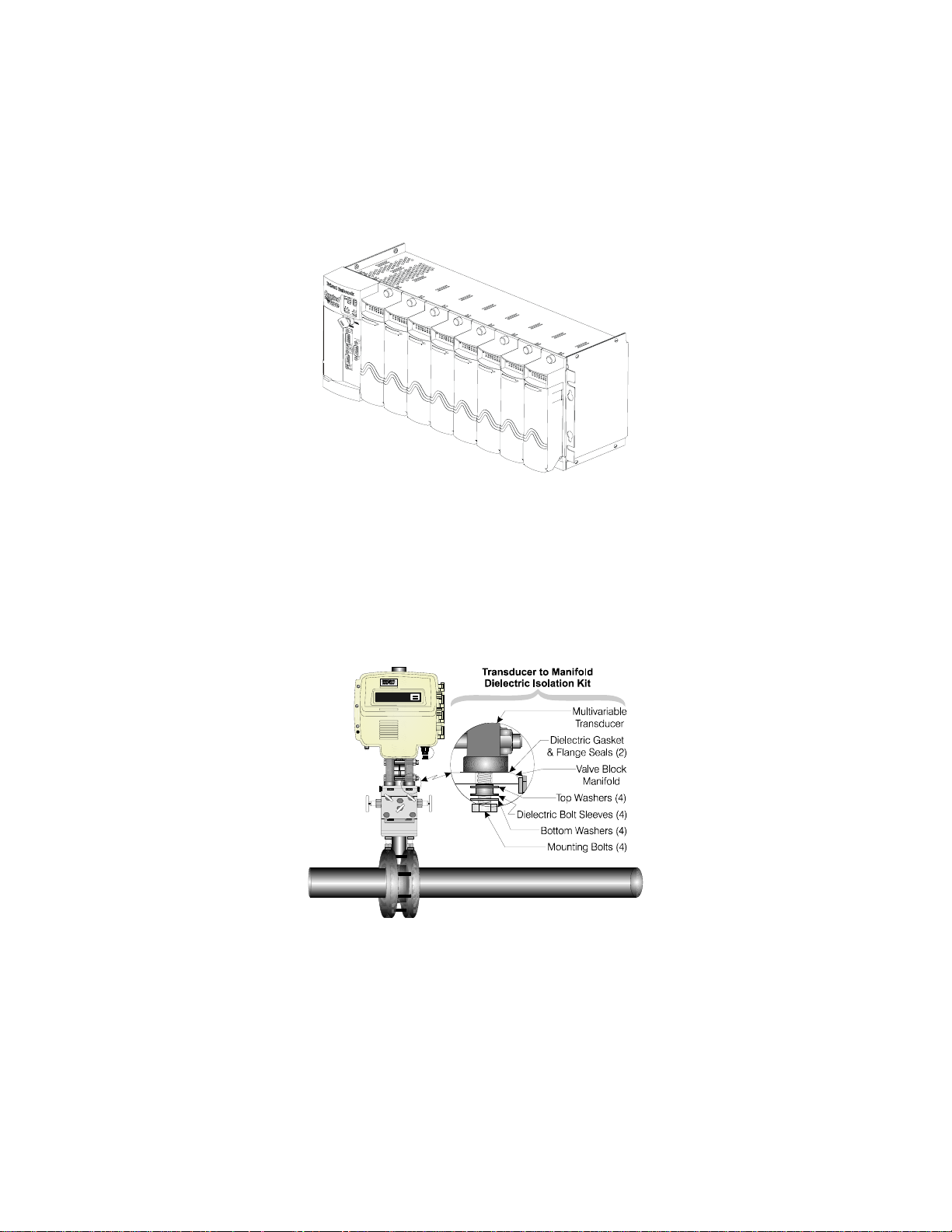
2.3.1.1 Connection to the Multivariable Transducer (MVT) .................................................. 2-10
2.3.1.2 Process Pipeline Connection (Meter Runs without Cathodic Protection) ................. 2-11
2.3.1.3 Process Pipeline Connection (Meter Runs with Cathodic Protection)....................... 2-11
2.3.2 System Controller Module (SCM) Configuration........................................................ 2-13
2.3.3 CPU Module & ECOM Module Configuration ............................................................ 2-14
2.3.3.1 CPU Module Switch Configuration .............................................................................2-14
2.3.3.2 Communication Ports................................................................................................... 2-16
2.3.3.3 RS-232 & RS-485 Interfaces ........................................................................................2-17
2.3.3.4 Piggy-back Spread Spectrum Modem (Radio) Port .................................................... 2-22
2.3.3.5 Piggy-back 56K PSTN Modem Port............................................................................. 2-23
2.3.3.6 Radio Ready and External (Case Mounted) Modem or Radio.................................... 2-27
2.3.4 I/O Module Installation & Wiring................................................................................ 2-27
2.3.4.1 Installation of I/O Modules ..........................................................................................2-27
2.3.4.2 I/O Wire Connections....................................................................................................2-30
2.3.4.3 Shielding and Grounding ............................................................................................. 2-30
2.3.4.4 Non-isolated Digital Input/Output Module................................................................. 2-30
2.3.4.4.1 Digital Input/Output Configurations .......................................................................... 2-30
2.3.4.5 Non-isolated Analog Input/Output & Analog Input Modules .................................... 2-31
2.3.4.5.1 Analog Input/Output Configurations ..........................................................................2-33
2.3.4.6 Non-isolated High Speed Counter Input Module........................................................ 2-33
2.3.4.6.1 High Speed Counter Configurations............................................................................ 2-35
2.3.4.7 Non-isolated Mixed I/O Module ................................................................................... 2-35
2.3.4.7.1 Mixed I/O Module Configuration ................................................................................. 2-37
2.3.5 RTD Wiring ................................................................................................................... 2-38
2.3.6 21V Power Supply Option ............................................................................................2-39
2.3.7 Digital to Relay I/O Board Option ...............................................................................2-40
2.3.7.1 Digital to Relay I/O Board Jumper Settings ............................................................... 2-40
2.3.8 Connection to a Model 3808 Transmitter.................................................................... 2-42
2.3.9 Power Wiring & Distribution ....................................................................................... 2-44
2.3.9.1 Bulk Power Supply Current Requirements ................................................................2-45
2.3.9.2 Power Wiring ................................................................................................................ 2-46
2.3.9.3 Mounting an Optional Solar Panel .............................................................................. 2-47
2.3.9.3.1 Swivel (Directional Facing) ..........................................................................................2-47
2.3.9.3.2 Tilt Angle....................................................................................................................... 2-48
2.3.9.4 Installing the Rechargeable Battery and Solar Panel Harness................................. 2-48
2.3.9.5 ControlWave EFM System Grounding...................................................................... 2-49
2.3.10 Operation of the Lithium Backup Coin-cell Battery .................................................. 2-49
2.3.11 Installation of a Bezel Assembly.................................................................................. 2-50
2.4 OPERATIONAL DETAILS .......................................................................................... 2-51
2.4.1 Downloading the Application Load.............................................................................. 2-51
2.4.2 Upgrading ControlWave EFM Firmware .................................................................2-51
2.4.2.1 Using LocalView to Upgrade ControlWave EFM Firmware ...................................2-52
2.4.2.2 Using Hyperterminal to Upgrade ControlWave EFM Firmware............................ 2-55
CI-ControlWave EFM Contents / 0 - 3
Page 13

CI-ControlWave EFM
ControlWave EFM
Electronic Flow Meter
TABLE OF CONTENTS
SECTION TITLE PAGE #
Section 2 - INSTALLATION & OPERATION (Continued)
2.4.2.3 Remote Upgrade of ControlWave EFM Firmware ................................................... 2-58
2.4.3 Operation of the Mode Switch...................................................................................... 2-59
2.4.4 Soft Switch Configuration and Communication Ports ...............................................2-59
2.4.5 Optional Display/Keypad Assemblies.......................................................................... 2-60
2.4.5.1 Operation of the Dual-button Display/Keypad Assembly ..........................................2-62
Section 3 - SERVICE
3.1 SERVICE INTRODUCTION ........................................................................................3-1
3.2 COMPONENT REMOVAL/REPLACEMENT PROCEDURES................................... 3-1
3.2.1 Accessing Modules For Testing...................................................................................... 3-1
3.2.2 Removal/Replacement of the Bezel Assembly............................................................... 3-2
3.2.3 Removal/Replacement of the CPU Module ................................................................... 3-2
3.2.4 Removal/Replacement of the System Controller Module ............................................. 3-2
3.2.5 Removal/Replacement of an I/O Module .......................................................................3-2
3.2.6 Removal/Replacement of an Expansion Comm. Module ..............................................3-3
3.2.7 Removal/Replacement of a Rechargeable Lead-acid Battery....................................... 3-3
3.2.8 Removal/Replacement of a Power Distribution Board .................................................3-4
3.2.9 Removal/Replacement of a 21V Power Supply Board .................................................. 3-5
3.2.10 Removal/Replacement of a Digital to Relay I/O Board................................................. 3-5
3.2.11 Removal/Replacement of an External Radio/Modem ................................................... 3-5
3.3 TROUBLESHOOTING TIPS......................................................................................... 3-5
3.3.1 System Controller Module (SCM) Voltage Checks ....................................................... 3-5
3.3.2 LED Checks .................................................................................................................... 3-6
3.3.3 Wiring/Signal Checks ................................................................................................... 3-10
3.4 GENERAL SERVICE NOTES..................................................................................... 3-10
3.4.1 Extent of Field Repairs................................................................................................. 3-11
3.4.2 Disconnecting RAM Battery ........................................................................................ 3-11
3.4.3 Maintaining Backup Files............................................................................................ 3-11
3.5 WINDIAG DIAGNOSTICS .......................................................................................... 3-11
3.5.1 Diagnostics Using WINDIAG ...................................................................................... 3-14
3.5.1.1 Communications Diagnostic Port Loop-back Test...................................................... 3-14
3.5.1.2 Serial Comm. Port Eternal Loop-back Test Procedure ..............................................3-14
3.6 CORE UPDUMP........................................................................................................... 3-16
3.7 CALIBRATION CHECKS............................................................................................ 3-16
Section 4 - SPECIFICATIONS
4.1 CPU, MEMORY & PROGRAM INTERFACE .............................................................. 4-1
4.2 COMMUNICATION PORTS ......................................................................................... 4-1
4.3 SYSTEM CONTROLLER MODULE ............................................................................ 4-2
4.3.1 Input Power Specs. ......................................................................................................... 4-2
4.3.2 Power Supply Sequencer Specs. .................................................................................... 4-3
0 - 4 / Contents CI-ControlWave EFM
Page 14

CI-ControlWave EFM
ControlWave EFM
Electronic Flow Meter
TABLE OF CONTENTS
SECTION TITLE PAGE #
Section 4 - SPECIFICATIONS (Continued)
4.3.3 Power Supply External Power Monitor Specs. ............................................................4-3
4.3.4 System Controller Module Connectors.......................................................................... 4-3
4.4 INPUT/OUTPUT MODULE SPECIFICATIONS......................................................... 4-4
4.4.1 Non-isolated Analog Input/Output Module................................................................... 4-4
4.4.2 Non-isolated Digital Input/Output Module ................................................................... 4-5
4.4.3 Non-isolated High Speed Counter Input Module.......................................................... 4-6
4.4.4 Non-isolated Mixed Input/Output Module .................................................................... 4-6
4.5 DIGITAL TO RELAY I/O BOARD SPECIFICATION ................................................. 4-9
4.6 21V POWER SUPPLY BOARD SPECIFICATIONS.................................................... 4-9
4.7 ENVIRONMENTAL SPECIFICATIONS.................................................................... 4-10
4.8 DIMENSIONS ..............................................................................................................4-10
APPENDICES/SUPPLEMENTAL INSTRUCTION
Special Instructions for Class I, Division 2 Hazardous Locations .................Appendix A
Reserved ............................................................................................................Appendix B
HARDWARE INSTALLATION GUIDE..........................................................Appendix C
ECOM MODULE RADIO/MODEM INSTALLATION GUIDE .................... Appendix D
DISPLAY/KEYPAD ASSEMBLY GUIDE.......................................................Appendix E
Using ControlWave EFM WebBSI Web Pages .............................................Appendix F
RADIO READY INSTALLATION GUIDE .................................................... Appendix G
MATERIAL SAFETY DATA SHEETS ........................................................... Appendix Z
Site Considerations for Equipment Installation, Grounding & Wiring ...........S1400CW
Care and Handling of PC Boards and ESD-Sensitive Components .....................S14006
REFERENCED Bristol CUSTOMER INSTRUCTION MANUALS
WINDIAG - Windows Diagnostics for BBI Controllers ........................................ D4041A
ControlWaveMICRO Quick Setup Guide ............................................................. D5124
Open BSI Utilities Manual ...................................................................................... D5081
Getting Started with ControlWave Designer.......................................................... D5085
Web_BSI Manual...................................................................................................... D5087
ControlWave Designer Reference Manual .............................................................. D5088
ControlWave Designer Programmer’s Handbook................................................... D5125
TechView User’s Guide............................................................................................. D5131
ControlWave Loop Power Supply Product Installation Guide........ PIP-ControlWaveLS
REFERENCED OEM MANUALS
Expansion Comm. Module Piggy-back Modem/Radio OEM Manuals
MDS Transnet Radio wired to Polyphaser - Spread Spectrum Data Transceiver
MDS document MDS 05-3946A01, Rev. A April, 2003 (PDF = 3946A-TNET_OEM-web.pdf)
CI-ControlWave EFM Contents / 0 - 5
Page 15

CI-ControlWave EFM
ControlWave EFM
Electronic Flow Meter
TABLE OF CONTENTS
SECTION TITLE PAGE #
REFERENCED OEM MANUALS (Continued)
Expansion Comm. Module Piggy-back Modem/Radio OEM Manuals (Continued)
Internal FreeWave Radio (wired to Polyphaser) - Spread Spectrum Data Transceiver
FreeWave Spread Spectrum Wireless Data Transceiver User Manual - V5.0R (model FGR09CSU)
Contact the FreeWave Tech Support group @ 303-444-3862 or at www.freewave.com to request the
latest copy of the user manual.
MultiTech Systems wired to Surge Suppressor - Modem Module MT3334SMI & MT5634SMI
MultiTech Systems Developer Guide PN S000181C, version C 6/24/02 (PDF = S000181C.pdf)
MDS Transnet 900 - Spread Spectrum Data Transceiver
MDS TransNET 900 Spread Spectrum Data Transceiver Installation & Operation Guide – MDS Doc.
MDS 05-2708A01, Rev. C, Feb., 2004 (PDF = 2708C-TransNET-web.pdf) for MDS TransNet 900
MDS 4710A – Remote Data Transceiver (Radio)
MDS 4710/9710 Series 400MHz/900 MHz Remote Data Transceiver Installation and Operation Guide
– MDS Doc. 05-3305A01, Rev. B, Sept. 2000
(PDF = 3305B-710AC.pdf) for model MDS 4710A
MDS 4710B – Data Transceiver (Radio)
MDS 4710B/9710B Data Transceiver Installation and Operation Guide – MDS Doc. 05-3316A01, Rev.
E, Sept. 2000
(PDF = 3316E-x710B.pdf) for model MDS 4710B
MDS 9810 – Spread Spectrum Data Transceiver (Radio)
MDS 9810/24810 900 MHz/2.4GHz Spread Spectrum Transceivers Installation and Operation Guide
– MDS Doc. 05-3301A01, Rev. B, April 2000
(PDF = 3301B-x810.pdf) for model MDS 9810
MDS 9710A Remote Data Transceiver (Radio)
MDS 4710/9710 Series 400MHz/900 MHz Remote Data Transceiver – MDS Doc. 05-3305A01, Rev. B,
Sept. 2000
(Installation & Operation) (PDF = 3305B-710AC.pdf) for model MDS 9710A
MDS 9710B Data Transceiver (Radio)
MDS 4710B/9710B Data Transceiver Installation and Operation Guide – MDS Doc. 05-3316A01, Rev.
E, Sept. 2000
(PDF = 3316E-x710B.pdf) for model MDS 9710B
External Modem/Radio OEM Manuals
0 - 6 / Contents CI-ControlWave EFM
Page 16

CI-ControlWave EFM
ControlWave EFM
Electronic Flow Meter
TABLE OF CONTENTS
SECTION TITLE PAGE #
REFERENCED OEM MANUALS (Continued)
External Modem/Radio OEM Manuals (Continued)
MDS iNET 900 Ethernet Radio
MDS iNET 900 Wireless IP/Ethernet Transceiver – User Guide = MDS 05-2806A01, Rev. D, Aug.
2003
(PDF = 2806D-iNET_User-web.pdf) for iNET 900 Ethernet Radio
Center Insert (Installation Reference Chart) = (PDF = 2873D-iNET_Center_Sheet.pdf)
MDS iNET 900 Wireless IP/Ethernet Transceiver – Installation Guide = MDS 05-2873A01, Rev. D,
Aug. 2003
(PDF = 2873D-iNET-Install_web.pdf) for iNET 900 Ethernet Radio
MDS entraNET Extended Range IP Networking Transceivers
MDS entraNET Extended Range IP Networking Transceivers – System Guide = MDS 05-4055A01,
Rev. A, Oct. 2003
(Installation & Operation) (PDF = 4055A-entraNET-web.pdf) for MDS entraNET 900 System
FreeWave Radio - Spread Spectrum Data Transceiver Model FGRM-501X005
Contact the FreeWave Tech Support group @ 303-444-3862 or at www.freewave.com to request the
latest copy of the user manual.
CI-ControlWave EFM Contents / 0 - 7
Page 17

Section 1
ControlWave EFM INTRODUCTION
1.1 GENERAL DESCRIPTION
ControlWave EFM electronic flow meters measure differential pressure, static pressure
and temperature for a single run and compute flow for both volume and energy. In addition
to operation in an unprotected outdoor environment, the ControlWave EFC electronic flow
meter provides the following key features.
• ARM processor provides exceptional performance and low power consumption
• Wide operating temperature range: (-40 to +70°C) (-40 to 158°F)
• CPU, SCM & I/O Modules provide LED status Indicators
• Battery backup for the real-time clock and the system’s SRAM is provided by a 3.0V,
300mA-hr lithium coin cell battery located on the CPU Module.
• Very low power consumption
• Integral Multivariable Transducer (MVT) with “smart” performance
• Standard Application Program supports the following Flow calculations:
• Calculates AGA3-1995/NX-19
• AGA3-1992 with selectable AGA8 Gross or AGA8 Detail
• AGA7/NX-19
• AGA7 with selectable AGA8 Gross or AGA8 Detail
• Auto Adjust AGA7/NX-19
• Auto Adjust AGA7 with selectable AGA8 Gross or AGA8 Detail
• Instromet Modbus AGA7 with selectable AGA8 Gross or AGA8 Detail
• Daniel Modbus AGA7 with selectable AGA8 Gross or AGA8 Detail
• Three serial communications ports (Two RS-232 & One RS-485)
• Four line alphanumeric display (with dual-button Keypad or 25-button Keypad)
• User choice of I/O Modules (AI/AO, AI, DI/DO, HSC and Mixed I/O)
• RTD input
• Nonincendive Class I, Div. 2, Groups C & D Hazardous Locations (see Appendix A)
• RTD input
• Optional Expansion Comm. Modules with/without built-in modem and/or radio
• Chassis Slots 3 and 4 support Expansion Comm. Modules or I/O Modules or one of each
• Optional Display/Keypad System
• Mixed I/O Modules provide cost effective I/O for small RTU applications
ControlWave EFC electronic flow meters are furnished in a NEMA 3X rated Hoffman®
Enclosure. The flow computer hardware is comprised of a Backplane Board (mounted in a
Housing), a System Controller Module and a CPU Module. Optional Expansion
Communication Modules may reside in Slots 3 and 4 of the Housing in lieu of I/O Modules.
The CPU Module utilizes Sharp’s LH7A400 System-on-Chip Advanced RISC Machine
(ARM) microprocessor with 32-bit ARM9TDMI Reduced Instruction Set Computer (RISC)
Core. In addition to the microprocessor and control logic, the CPU Board includes two RS232 communication ports, one RS-485 Communication port, 2MB of battery backed Static
RAM (SRAM), 512kB Boot/Downloader FLASH, 8MB simultaneous read/write FLASH, and
an I/O Bus Connector.
All system modules plug into the Backplane Board (4-Slot or 8-Slot). Each I/O Module
provides the circuitry and field interface hardware necessary to interconnect the assigned
field I/O circuits. Non-isolated power is generated and regulated by the System Controller
Module (SCM) that provides +3.3Vdc for all logic and bulk power for I/O field circuits from
either a bulk 6Vdc or bulk 12Vdc source. +1.8Vdc, used by the ARM microprocessor, is
CI-ControlWave EFM Introduction / 1-1
Page 18
generated on the CPU Module (derived from the regulated 3.3Vdc logic power). In addition
to Idle and Watchdog LEDs, there are six status LEDs located on the SCM that will display
run time status information.
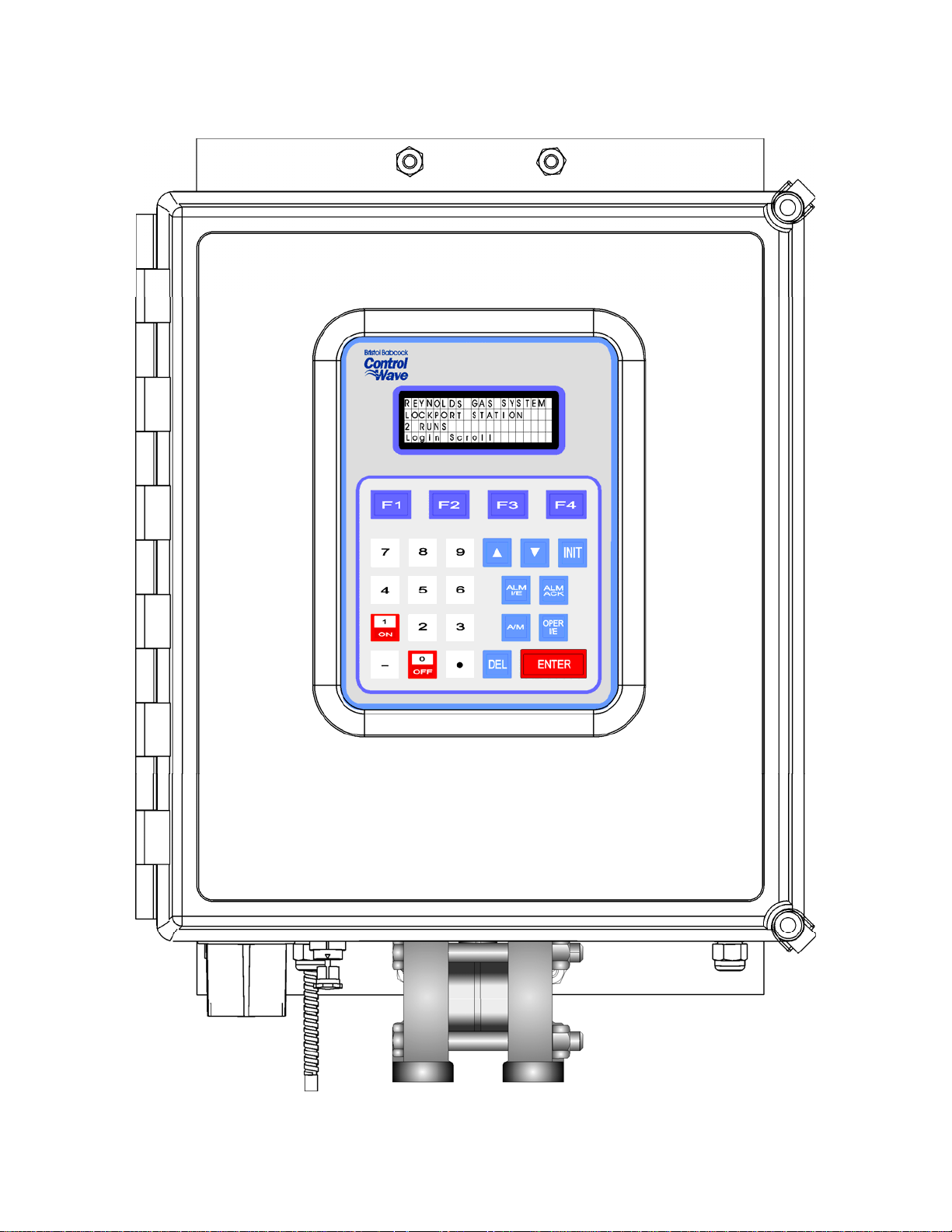
Figure 1-1 - ControlWave EFM Enclosure
(with 25-Button Display/Keypad Assembly)(Shown with Circular Local Port)
1-2 / Introduction CI-ControlWave EFM
Page 19
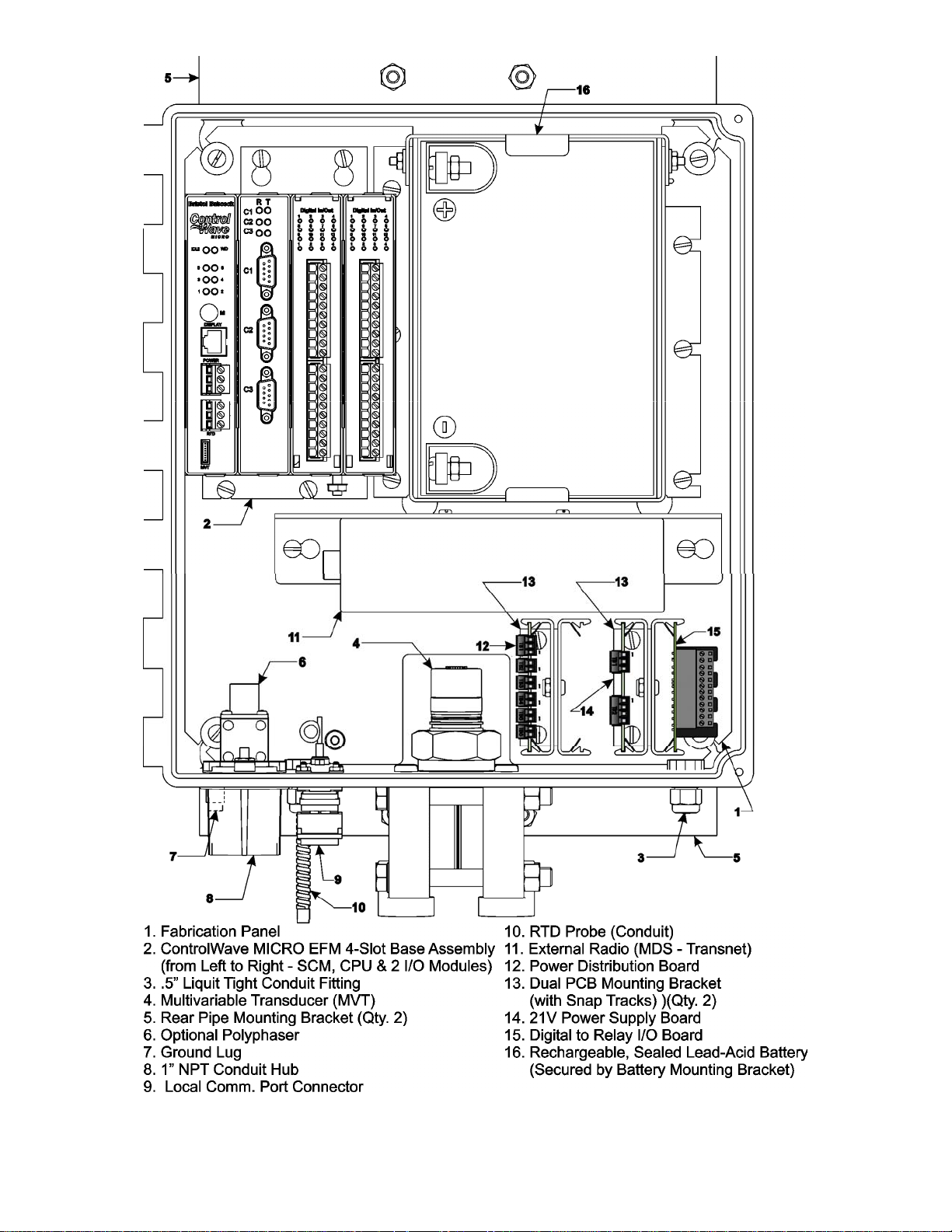
Figure 1-2A - 4-Slot ControlWave EFM (Internal View)
Component Identification Diagram (Shown with D-Type Local Port)
CI-ControlWave EFM Introduction / 1-3
Page 20
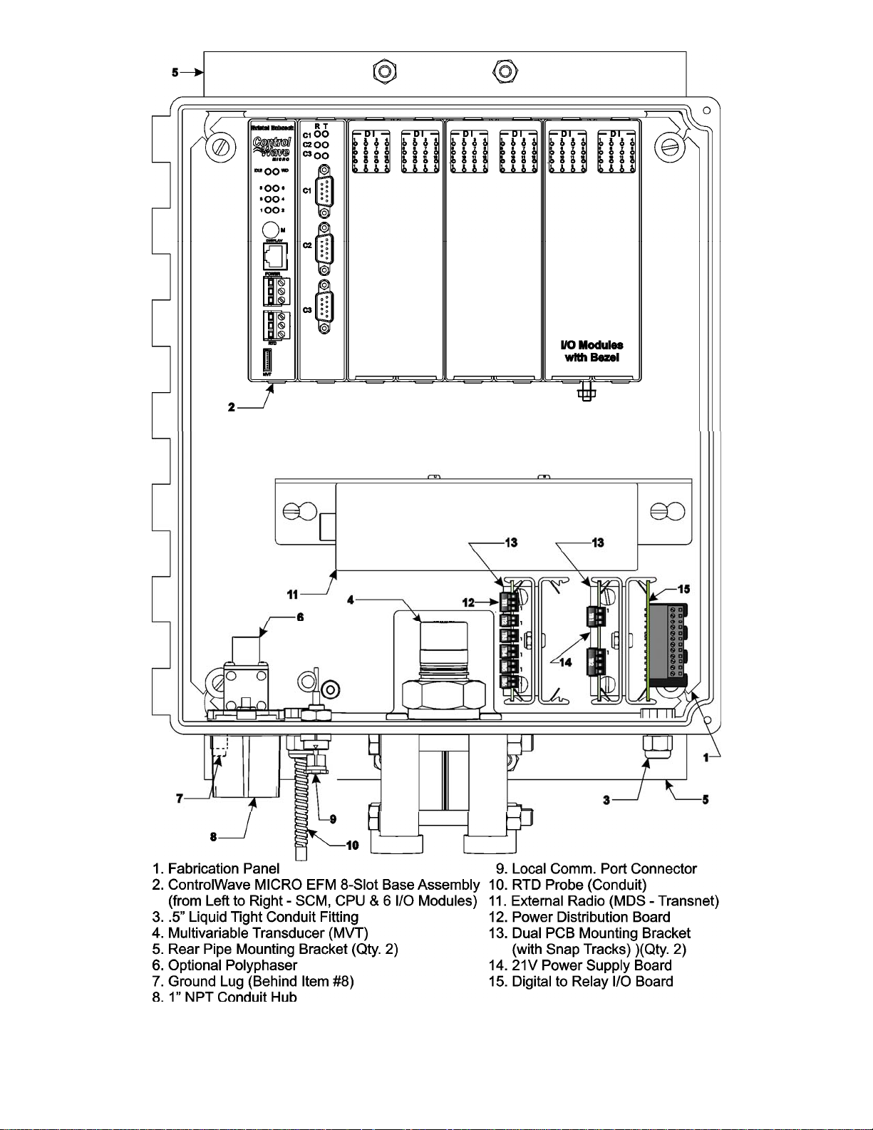
Figure 1-2B - 8-Slot ControlWave EFM (Internal View)
Component Identification Diagram (Shown with Circular Local Port)
1-4 / Introduction CI-ControlWave EFM
Page 21
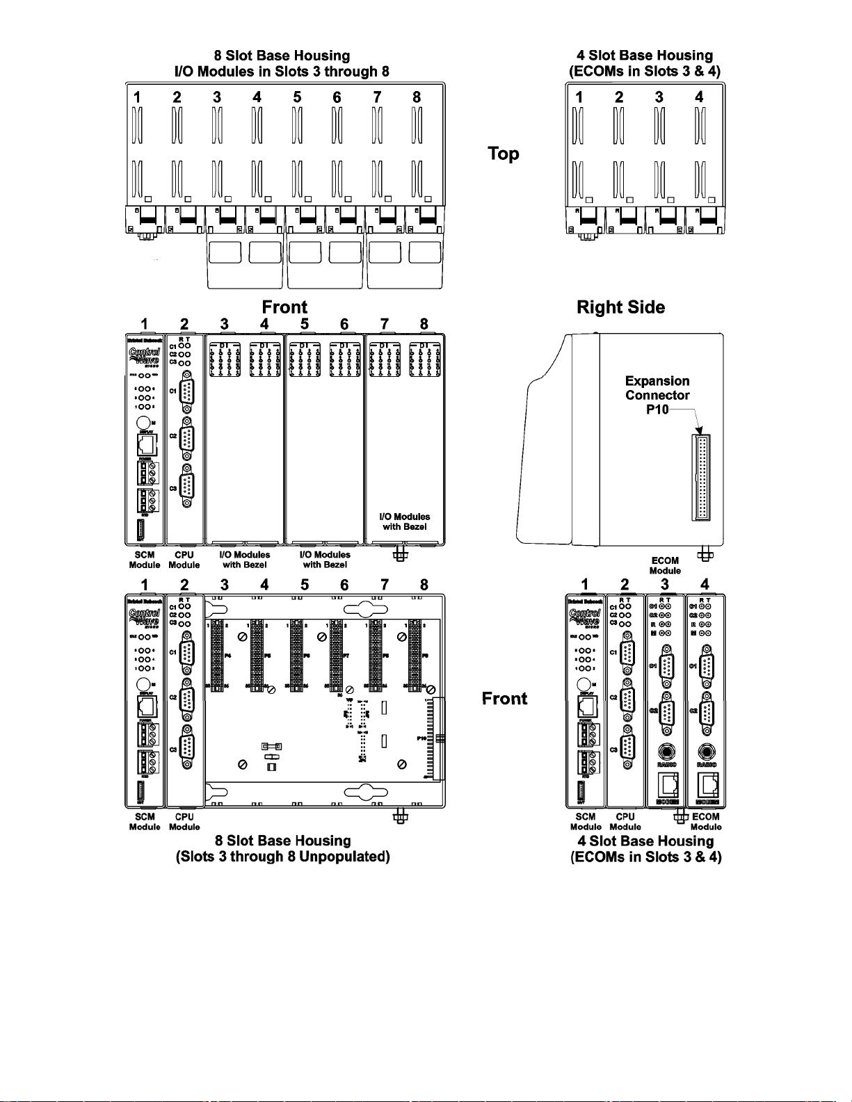
Figure 1-3 - 8/4-Slot ControlWave EFM (Electronic Flow Meter) Base Assemblies
(The 4-Slot Chassis is shown with ECM Modules in Slots 3 & 4)
1.2 ControlWave PROGRAMMING ENVIRONMENT
The ControlWave programming environment uses industry-standard tools and protocols to
provide a flexible, adaptable approach for various process control applications in the water
treatment, wastewater treatment, and industrial automation business.
CI-ControlWave EFM Introduction / 1-5
Page 22

ControlWave EFM units provide an ideal platform for remote site automation,
measurement, and data management in the oil and gas industry.
The control strategy file created and downloaded into the controller is referred to as a
ControlWave project. The ControlWave EFM ships from Bristol Babcock with a
standard ControlWave project, pre-configured for gas flow measurement, already loaded
and ready to run.
The ControlWave programming environment consists of a set of integrated software tools
which allow a user to modify the standard gas flow measurement project to fit the needs of
their own particular application, as well as to create, test, implement, and download a
different ControlWave project, if desired.
The tools that make up the programming environment are:
• ControlWave Designer load building package offers several different methods for
generating and debugging control strategy programs including function blocks, ladder
logic, structured languages, etc. The resulting process control load programs are fully
compatible with IEC 61131-3 standards. Various communication methods as offered,
including TCP/IP, serial links, as well as communication to Bristol Babcock’s Open BSI
software and networks
.
Figure 1-4 - ControlWave - Control Strategy Software Diagram
• The I/O Configuration Wizard, accessible via a menu item in ControlWave Designer,
allows you to define process I/O modules in the ControlWave and con-figure the
individual mapping of I/O points for digital and analog inputs and outputs.
• The ACCOL3 Firmware Library which is imported into ControlWave Designer,
includes a series of Bristol Babcock specific function blocks. These pre-programmed
1-6 / Introduction CI-ControlWave EFM
Page 23

function blocks accomplish various tasks common to most user applications including
alarming, historical data storage, as well as process control algorithms such as PID
control.
• The OPC Server (Object Linking and Embedding (OLE) for Process Control) allows
real-time data access to any OPC [Object Linking and Embedding (OLE) for Process
Control] compliant third-party software packages.
• A set of ControlWave EFM web pages is provided to set configuration parameters for
the standard gas flow measurement project, running in the unit. These web pages use
Bristol Babcock-specific ActiveX controls for retrieval of real-time data values and
communication statistics from the unit. The ActiveX controls are compatible with
Microsoft® Internet Explorer. Alternatively, developers can place the ActiveX controls
in third-party ActiveX compatible containers such as Visual BASIC or Microsoft® Excel.
• User-defined Web Pages – Users can place the same ActiveX controls into their own
web pages to provide a customized human-machine interface (HMI) to the Control-
Wave EFM.
• Flash Configuration Utility – Parameters such as the BSAP local address, IP ad-
dress, etc. are set using the Flash Configuration Utility, accessible via Open BSI
LocalView or NetView. The ControlWave EFM ships with a standard Flash Configuration Profile (FCP) file, with default configuration parameters already set.
1.3 PHYSICAL DESCRIPTION
ControlWave EFM electronic flow meters are comprised of the following major com-
ponents:
• Enclosure with Local Communications Port (RS-232) and LCD Display (Section 1.3.1)
• CPU Module (Section 1.3.2)
• System Controller Module (Section 1.3.3)
• Backplane (Section 1.3.4)
• Base Assembly (Chassis) (Section 1.3.5)
• Up to two I/O Modules (Section 1.3.6) or two Expansion Communication Modules (see
Section 1.3.7) - (or one of either, one of each, or none)
• Internal Mounting Brackets (Section 1.3.8)
ControlWave EFMs can be factory configured with the following options:
• Multivariable Transducer (Section 1.3.9)
• Power Distribution Board (Section 1.3.10)
• Digital to Relay I/O Board (Section 1.3.11)
• 21V Power Supply Board (Section 1.3.12)
• Power System - Solar Panel (30W) & 33AH Lead-acid Battery (with Battery Charger/-
Power Manager Board (Section 1.3.13)
• RTD Probe (Section 1.3.14)
• External Radio/Modem (Section 1.3.15)
CI-ControlWave EFM Introduction / 1-7
Page 24

1.3.1 Enclosure
ControlWave EFMs are housed in a standard Hoffman® Enclosure. External dimensions
(excluding added hardware and Cover Latches) are approximately 14.56” high, by 12.97”
wide, by 8.31” deep. When present, the Multivariable Transducer adds 2.89” to the height of
the unit. The enclosure consists of two pieces, the body and the Instrument Front Cover. A
continuous gasket seals the unit when the Instrument Front Cover is closed. A hinge on the
left side (facing the front of the unit) is formed by molded channels on the Instrument Front
Cover and the body that capture a stainless steel pin. Two latches on the enclosure’s right
side secure the Instrument Front Cover when it is closed.
A weatherproof communication connector, either a 9-Pin male D-Type connector or a a
circular 3-pin connector, (the Local Port) is mounted to the bottom of the enclosure and
connected internally to RS-232 Comm. Port 1 provides connection for a local
communications device, typically a PC. Communications rate is configurable 300 to 115.2
KB (115.2 KB - default).
Enclosures are provided with either a 2-button 4 X 20 LCD display or a 4 X 20 LCD display
supported by a 25-button keypad. In normal operation, the display stays off after the unit
has been configured and placed into service. The operator may activate the display at any
time by pressing the appropriate front panel button.
1.3.2 CPU Module
The CPU Module houses the CPU Board. This multilayer board provides ControlWave
MICRO EFM CPU, I/O monitor/control, memory and communication functions. Control-
Wave MICRO EFM CPU Modules operate over an extended temperature range with longterm product reliability.
ControlWave EFM CPU Boards are based on Sharp’s LH7A400 System-on-Chip ARM
microprocessor with 32-bit ARM9TDMI RISC Core. The CPU operates at 1.8V with a
system clock speed of 33 MHz. The Microcontroller is packaged in a 256-pin Plastic Ball
Grid Array. In addition to the microprocessor and control logic, the CPU Board includes two
RS-232 and one RS-485 communication ports, 2MB of battery backed Static RAM (SRAM),
512kB Boot/Downloader FLASH, 8MB simultaneous read/write FLASH and an I/O Bus
Connector.
CPU Modules are provided backup power via a piggyback mounted Battery Backup board
equipped with a coin cell socket that accepts a 3.0V, 300mA-hr lithium battery. This 3.0V
battery provides backup power for the real-time clock and the system’s Static RAM (SRAM).
Backup power is enabled when JP1 on the Battery Backup Bd. is installed.
If the 3.3Vdc that powers the unit goes out of specification, a supervisory circuit on the
Battery Backup Board switches the battery voltage to the VBAT3.3 hardware signal (used
by the CPU’s SRAM and RTC). This supervisory circuit also generates a BATTERYGOOD
signal when the battery voltage is above 2.2V.
The system SRAM is specified to have a standby current of 20:A maximum for each part
(plus 2uA for the RTC). For a system containing 2MB of System SRAM, a worst-case
current draw of 42:A allows a battery life of approximately 7142 hours.
A supervisory circuit is used to switch to battery power when VCC falls out of specification.
For maximum shelf life, the battery may be isolated from the circuit by removing the
1-8 / Introduction CI-ControlWave EFM
Page 25
Backup Battery Jumper JP1 (on the Battery Backup Board) from position 1 to 2 and then
storing it on either pin. If the Real-time clock looses its battery backup a ControlWave
Designer system variable bit (_QUEST_DATE) is set. This bit can be used to post a
message or alarm to the PC (see the ‘Systems Variables’ section of the ControlWave
Designer Programmer’s Handbook D5125).
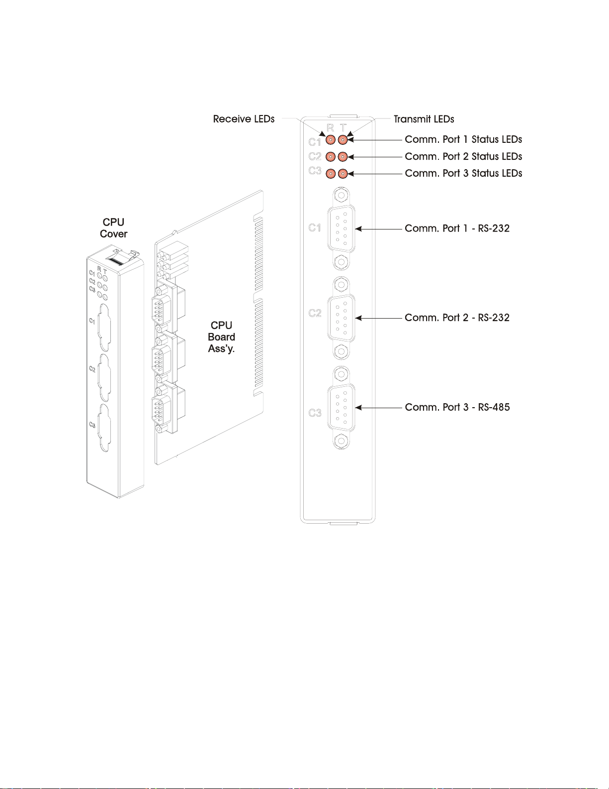
Figure 1-5 – ControlWave EFM CPU Module
Basic CPU components and features are summarized as follows:
• LH7A400 System-on-Chip 32-bit ARM9TDMI RISC Core microprocessor
• 512KB FLASH Boot/Downloader, 29LV040B, 90 nS, 8-bit access
• 2MB SRAM, 3.3V, 512K x 32, with Battery Back-up
• 8MB simultaneous read/write FLASH, TSOP sites
• Two 9 wire PC2 compatible (RS-232) serial communications ports with modem control
pins and one 5 wire RS-485 Comm. port
• I/O Bus Interface capable of driving up to 14 I/O Modules
• Spread Spectrum clock for lower EMI
• Two Status LEDs per Comm. Port
• 8-Position general-purpose switch bank plus a 4-Position recovery switch bank
• Coin cell socket accepts a 3.0V, 300mA-hr lithium battery
CI-ControlWave EFM Introduction / 1-9
Page 26

1.3.2.1 CPU Module Connectors
The CPU Modules contain up to seven connectors that function as follows (see Table 1-1):
Table 1-1 - CPU Board Connector Summary
Ref. # Pins Function Notes
P1 76-Pin Factory Debug Not user accessible
P2 36-pin Card Edge Backplane I/O Bus Intf. see Figure 2-9
P3 44-pin Card Edge Backplane SCM Intf. see Figure 2-8
J2 10-Pin PLD JTAG Header Not user accessible
J3 9-pin COM1 9-pin male D-sub (RS-232) see Figure 2-11 & Table 2-3 or 4-2
J4 9-pin COM2 9-pin male D-sub (RS-232) see Figure 2-11 & Table 2-3 or 4-2
J5 9-pin COM3 9-pin male D-sub (RS-485) see Figure 2-11 & Table 2-3 or 4-2
CPU Module Comm. Port Connectors J3, J4 and J5
The CPU Module supports up to two external 9-pin RS-232 serial communication ports
(COM1 and COM2) and an external 9-pin RS-485 serial communication port (COM3).
COM1 and COM2 and COM3 utilize standard 9-pin male D-sub connectors. RS-232 ports
are protected with LCDA12C devices to ±4KV ESD. RS-485 port COM3 is protected with
LCDA12C and LCDA05 devices to ±4KV ESD.
CPU Module I/OB Connector P2
CPU Module I/O Bus connector P2 provides a 36-pin interface between slot #2 (P3) of the
Backplane PCB and the CPU Module. Separate data, address and control buffers provide
access to the I/O bus which in turn provides up to 14 slots of memory mapped I/O Modules.
The CPU Module interface to the I/O Modules is through a set of buffers and transceivers
that are capable of driving up to fourteen I/O Modules.
CPU Module/System Controller Module Interface Connector (P3)
CPU Module/System Controller Module Interface connector (P3) provides a 44-pin interface
between slot #2 (P2) of the Backplane PCB and the CPU Module. The SCM provides:
- a wide input range Vin to 3.3V DC to DC Converter
- 1200 Millisecond good power detection
- Vin out of Spec. detection
- LED Status indication
1.3.2.2 CPU Memory
Boot/downloader FLASH
Boot/download code is contained in a single 512Kbytes uniform sector FLASH IC. This
device resides on the local bus, operates at 3.3V and is configured for 8-bit access. 4Position DIP-Switch SW1’s position 3 allows start-up menu options to be displayed or bootup from system FLASH. If SW1-3 is closed when a reset occurs, the boot-up code will cause
a recovery menu to be sent out the COM1 serial port to a terminal program running on an
external host computer. Note: Recovery Mode will also be initiated if SCM Switch SW1
positions 1 and 2 are both set OPEN (Right) or CLOSED (Left) when a reset occurs.
FLASH Memory
The base version of the CPU Module has 8Mbytes of 3.3V, simultaneous read/write (DL)
FLASH memory. Each CPU Board contains two 48-pin TSOP sites that will each accept 4
or 8 Mbytes of 3.3V, (DL) FLASH IC, for a total of 4 or 8 Mbytes of memory. FLASH
1-10 / Introduction CI-ControlWave EFM
Page 27

memory is 32-bits wide. System Firmware and the Boot Project are stored here. No
hardware write protection is provided for the FLASH array.
System Memory (SRAM)
The base version of the CPU Module has 2Mbytes of soldered-down static RAM, implemented with two 512K x 16 asynchronous SRAMs that are configured as a 512K x 32-bit
array. During power loss periods, SRAM is placed into data retention mode (powered by a
backup 3.0V lithium battery). SRAMs operate at 3.3V and are packaged in 44-pin TSOPs.
Critical system information that must be retained during power outages or when the
system has been disabled for maintenance is stored here. Data includes: Last states of all
I/O, historical data, retain variables and pending alarm messages not yet reported. The
SRAM supports 32-bit accesses and is connected to the GP bus.
1.3.2.3 CPU Module Configuration Jumpers
ControlWave EFM CPU Modules are provided with three User Configuration Jumpers
that function as follows:
• JP1 - Battery Backup Disable Jumper - On the Battery Backup Board - When JP1 is
removed, the CPU Module backup battery is disabled.
• JP4 - Status LEDs Disable Jumper - When JP4 is removed, the Status LEDs and the Idle
LED on the System Controller Module (SCM) are disabled.
• JP7 - Comm. port Status LEDs Disable Jumper - When JP7 is removed the CPU Comm.
Port Status LEDs are disabled.
1.3.2.4 CPU Module Configuration Switches
Three user configurable DIP-Switches are provided on the CPU Board; eight-bit DIP-
Switch SW2 is provided for user configuration settings while four-bit DIP-Switch SW1
provides forced recovery functions. Eight-bit DIP-Switch SW3 provides loopback,
termination control, and receiver bias settings for the RS-485 port (COM3).
Table 1-2 - Assignment of CPU Bd. Switch SW2 - User Configurations
Switch Function Setting
SW2-1 Watchdog Enable
SW2-2
SW2-3
SW2-4
SW2-5 SRAM Control
SW2-6
SW2-8 Enable WINDIAG
Lock/Unlock
Soft Switches
Use/Ignore
Soft Switches
Core Updump
See Section 3.6
System Firmware
Load Control *
ON = Watchdog circuit is enabled
OFF = Watchdog circuit is disabled
ON = Write to Soft Switches or FLASH files
OFF = Soft Switches, configurations and FLASH files are locked
ON = Use Soft Switches (configured in FLASH)
OFF = Ignore Soft Switch Configuration and use factory defaults
ON = Core Updump Disabled
OFF = Core Updump via Mode Switch (SW1) on SCM
ON = Retain values in SRAM during restarts
OFF = Force system to reinitialize SRAM
ON = Enable remote download of System Firmware
OFF = Disable remote download of System Firmware
ON = Don’t allow WINDIAG to run test
OFF = Disable boot project and allow WINDIAG to run test
* = Boot PROM version 4.7 or higher and System PROM version 4.7 or higher
CI-ControlWave EFM Introduction / 1-11
Page 28

Table 1-3 - Assignment of CPU Bd. Switch SW1
Force Recovery Mode
Switch Function Setting
SW1-3 Force Recovery Mode
ON = Force recovery mode (via CW Console)
OFF = Recovery mode disabled
Table 1-4 - Assignment of CPU Module Switch SW3
COM3 -
Loopback & Termination Control
Switch RS-485 Function Setting
SW3-1 TX+ to RX+ Loopback ON - Only for Diagnostics
SW3-2 TX- to RX- Loopback ON - Only for Diagnostics
SW3-3 100 Ohm RX+ Termination ON - End Nodes Only
SW3-4 100 Ohm RX- Termination ON - End Nodes Only
SW3-7 RX+ Bias (End Node) ON - End Nodes Only
SW3-8 RX- Bias (End Node) ON - End Nodes Only
1.3.2.5 CPU Module LEDs
ControlWave EFM CPU Modules have six (6) LEDs on the CPU Board. Units equipped
with an optional Ethernet Port have two (2) additional LEDs (situated on the Ethernet RJ45 connector). Table 1-5 provides CPU Module LED assignments. An ON LED indicates an
associated transmit (TX) or receive (RX) activity.
Table 1-5 - Assignment of CPU Module LEDs
LED Ref. LED Function
C1 TX COM1
C1 RX COM1
C2 TX COM2
C2 RX COM2
C3 TX COM3
C3 RX COM3
1.3.3 System Controller Module (SCM)
The System Controller Module (SCM) plugs into the system’s Backplane Board slot #1
(Connector P1 - a 44-pin female non-keyed header). The front of the SCM contains two
pluggable terminal blocks for external, input power (TB1) and RTD (TB2 - future) connections. An RJ-45 connector provides the interface to a remote Display/Keypad Assembly. Two
red LEDs, visible through the front panel, provide for the following status conditions when
lit: WD (Indicates a Watchdog condition has been detected) & IDLE (Indicates that the
CPU has free time at the end of its execution cycle. Normally, it should be ON most of the
time. When the Idle LED is OFF, it indicates that the CPU has no free time, and may be
overloaded). Six status LEDs provide run time status codes.
SCMs contain a DC to DC power supply that generates a +3.3Vdc supply for the entire unit,
i.e., the CPU and various I/O Modules that plug into the Backplane Board. Also contained
on the SCM is the sequencer circuit that monitors the external power supply as well as the
logic supplies (3.3Vdc and 1.8Vdc on the CPU Board). The sequencer circuit has a
reset/early power fail warning controller that is utilized by the CPU Board to generate a
master reset (MRESET) to the rest of the system and to generate a power fail interrupt to
the CPU.
1-12 / Introduction CI-ControlWave EFM
Page 29
The power supply operates from +4.5/+4.9 to +16Vdc or +9.6/10.3 to +16Vdc with the
y
m
nominal input supply configuration (+6V or +12V) user configured via on-board jumpers. A
supervisory circuit monitors the incoming power and the supply voltages. The isolated
supplies are shut down when the incoming voltage drops below +4.5V for a +6V system or
+9.6V, for a +12V system.
An external battery monitor is composed of an Analog to Digital Converter (ADC) and
interface circuitry.
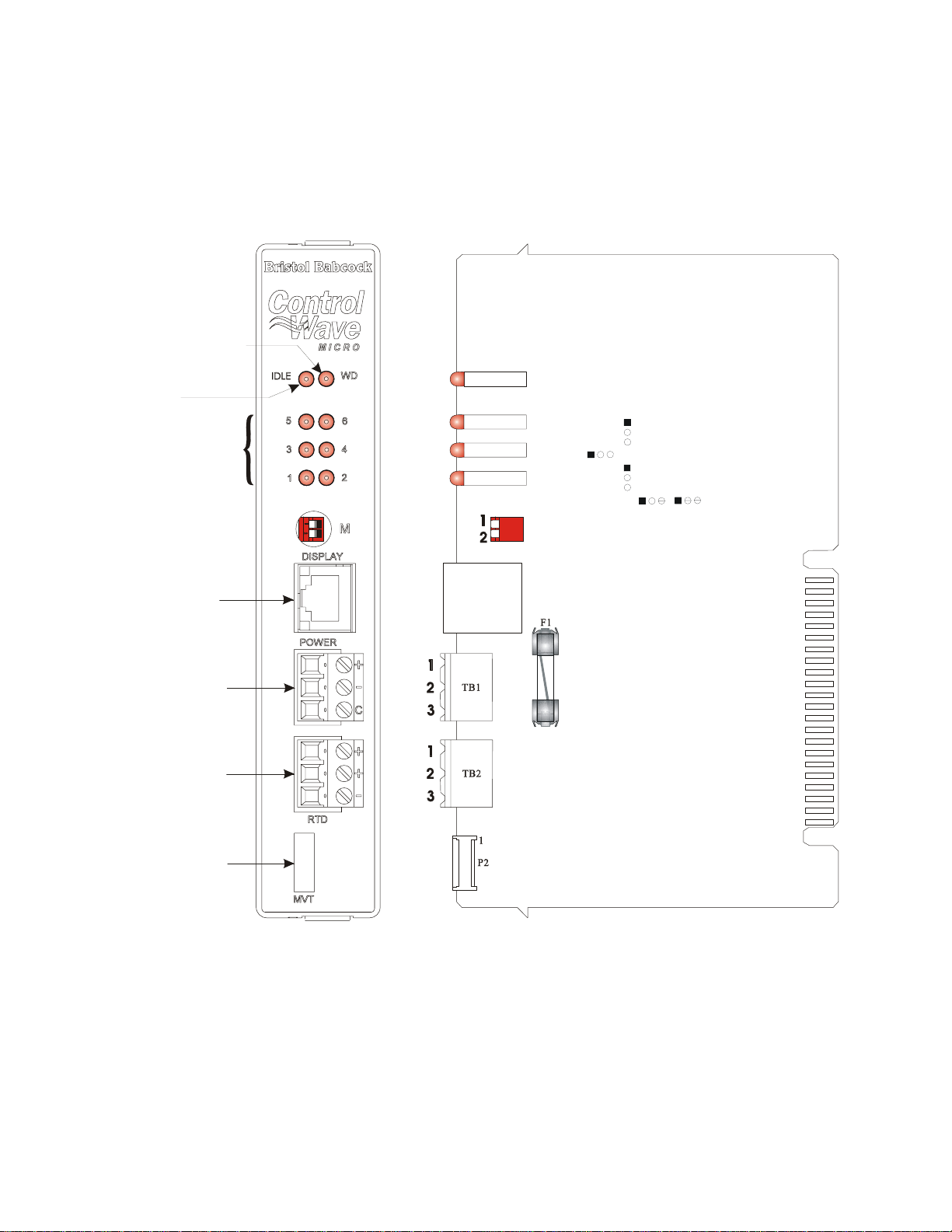
WATCHDOG LED
(Red)
IDLE LED
(Red)
Sta us LEDs
(Red)
J2
Display Intf.
Connector
TB1
Input Power
Connector
TB2
RT D Inte rfa ce
Connector
CR27
CR26
CR25
CR24
J2
RJ- 45
JP5, JP6, JP7, JP8 & JP9
1-to-2 Installed = 12V Bulk System
2-to-3 Installed = 6V Bulk System
1
JP6
JP7
1
SW1 = Mode Switch
1A
1
JP5
JP8
1
JP9
1
2
P1
P2
MVT Interface
Connector
JP1 - Factory Configured
(Not Shown)
JP5 - Power Fail Trip Point Selection
1-to-2 Installed = 12V Bulk System
2-to-3 Installed = 6V Bulk System
JP6 - Supply Shutdown Trip Point Selection
1-to-2 Installed = 12V Bulk System
2-to-3 Installed = 6V Bulk System
(+4.5/4.9Vdc to +16.0Vdc for +6V supply)
+VIN (+9.6/10.3Vdc to +16.0Vdc for +12V supply)
TB1 - 1
-VIN (Supply Ground)
TB1 - 2
Chassis Ground (CHASSIS)
TB1 - 3
JP7 - 1.2V Reference Source Current Selection
1-to-2 Installed = 12V Bulk System
2-to-3 Installed = 6V Bulk System
JP8 - Supply Shutdown Trip Point Hysterisis
1-to-2 Installed = 12V Bulk System
2-to-3 Installed = 6V Bulk System
JP9- Power Fail Trip Point Hysterisis
1-to-2 Installed = 12V Bulk System
2-to-3 Installed = 6V Bulk S
ste
Figure 1-6 - ControlWave EFM System Controller Module
CI-ControlWave EFM Introduction / 1-13
Page 30

1.3.3.1 SCM Mode Switch
SCM Module’s Mode Switch (SW1), is a 2-position piano type DIP-Switch that is utilized for
recovery mode and core updump operations (see Sections 2.4.3 and 3.6)
1.3.3.2 SCM Board Fuse
The SCM is fused to protect the entire system. 5x20mm Slow Blow Fuse F1 is rated at 1A.
1.3.3.3 SCM Board Connectors
Connectors TB1, TB2, J1, J2 and P2 function as described below.
SCM Bd. Terminal Block Connector TB1
TB1 provides 3 input connections for bulk power:
TB1-1 = +VIN (+4.5/4.9 to +16.0V dc for +6Vdc supply)
(+9.6/10.3V to +16V dc for +12Vdc supply)
TB1-2 = -VIN (Supply Ground - PSGND)
TB1-3 = Chassis Ground - CHASSIS (
)
SCM Bd. Terminal Block Connector TB2
TB2 provides 3 connections for a 100-ohm platinum bulb (DIN 43760 curve) RTD:
TB2-1 = RTD + (Sense or Excitation)
TB2-2 = RTD + (Sense or Excitation)
TB2-3 = RTD – (Return)
SCM Bd. Connector P2
P2 is an 8-pin non-keyed male in-line connector that mates with the Multivariable
Transducers (MVT) Interface Cable’s female connector.
SCM Bd. Connector P1
P1 is a 44-pin non-keyed male card-edge connector that mates with Backplane connector P1
(slot #1) and interfaces Power, Ground, Status and Control signals to the system.
SCM Bd. Connector J2
RJ-45 Connector J2 provides an interface to a remote Display/Keypad Assembly.
1.3.3.4 SCM Jumpers
ControlWave EFM SCM Modules are provided with six User Configuration Jumpers (see
Figure 1-6 for jumper functionality).
1.3.3.5 SCM LEDs
In addition to WATCHDOG and IDLE LEDs, the SCM contains six status LEDs, which are
driven by a status register on the CPU Module. These LEDs are visible through the front
panel and provide run time status codes (see Section 2.4.2 or Section 3.3.2).
1-14 / Introduction CI-ControlWave EFM
Page 31

1.3.4 ControlWave EFM Backplanes
4-Slot or 8-Slot ControlWave EFM Backplanes provide for the electrical interconnection of
the System Controller Module (SCM), CPU Module, Expansion Communication Modules
(ECOMs) and/or I/O Modules. One or two Expansion Comm. Modules may be substituted
for I/O Modules in Backplane slots 3 & 4. Backplane module slot connections that support
Expansion Comm. Modules (slots 3 & 4) or I/O Modules (slots 3 through 8) are implemented
via 36-pin female Headers.
The main complement of signals on the Backplane, implement an I/O bus for data transfer
between the CPU and I/O Modules. Note: I/O Modules are Non Interrupt Capable.
+3.3Vdc and GND from the SCM are connected to the CPU. All I/O Module slot positions
receive +3.3Vdc and GND. Additionally, the SCM supplies switched field power
(FIELDVOUT) to all I/O Module slots. The power supply sequencer circuit (within the
SCM) provides POWERGOOD, POWERFAIL, VIN100M and PFDLYCLK signals to the
CPU thus providing properly timed early warning of low input or supply voltages followed
by a CPU reset to support the WARM START CPU function.
Figure 1-7 - Backplane Board Diagram
1.3.5 ControlWave EFM Base Assembly Chassis
A Gold Irridite Aluminum Chassis supports the ControlWave EFM Backplane PCBs and
the modules that comprise the system (see Figs. 1-3 & 4-3). Dimensions are provided in
Section 4 of this manual (see Figures 4-3 and 4-4 for 4-Slot and 8-Slot Chassis,
respectively).
CI-ControlWave EFM Introduction / 1-15
Page 32

The unit’s Base Assembly Chassis is mounted to the Fabrication Panel inside the Hoffman
Enclosure. ControlWave EFM Chassis’ contain a Ground Lug that accommodates up to a
#4 AWG Ground Wire. Grounding the unit is accomplished by connecting a ground wire
between the Ground Lug and a known good Earth Ground.
1.3.6 ControlWave EFM I/O Modules
Five unique I/O Modules are available factory configured for either local or remote field
device wiring termination. I/O Modules provide Configuration Jumpers that accommodate
individual field I/O user configuration. Terminations are pluggable and accept a maximum
wire size of 14 gauge. All I/O have surge protection that meets C37.90-1978 and IEC 801-5
specifications. Each I/O Module is connected to the ControlWave EFM Back-plane via a
36-pin male card-edge connector. With the exception of the Mixed Input/Output Module, all
I/O Modules are provided with two 10-point Terminal Block Assemblies (for local
termination) or two 14-pin Mass Termination Headers (for remote termination). Mixed I/O
Modules are provided with two 10-point Terminal Block Assemblies (for local termination).
A brief overview of each I/O Module type is provided below. Specifications are covered in
Section 4.4.
Figure 1-8 - Two ControlWave EFM I/O Modules (with Bezel)
1-16 / Introduction CI-ControlWave EFM
Page 33

1.3.6.1 Non-isolated Analog I/O & Analog Input Modules (also see Section 2.3.4.5)
ControlWave EFM AI/O Modules provide 6 Analog Inputs and optionally 2 Analog
Outputs. All Analog Inputs are externally sourced, single-ended and individually Jumper
configurable for either 4-20mA or 1-5Vdc. Analog Outputs are externally sourced and are
individually Jumper configurable for 4-20 mA or 1-5 Vdc. 30Vdc Transorbs provide surge
suppression between each signal and ground. Analog Input Modules are identical to AI/O
Modules but have a depopulated AO section.
1.3.6.2 Non-isolated Digital Input/Output Module (also see Section 2.3.4.4)
ControlWave EFM DI/O Modules provide 12 Digital Inputs and 4 Digital Outputs. All
Digital Inputs support dry contact inputs internally sourced from the 3.3 Vdc supply and a
jumper selectable input current range of 60 uA (for low power applications) or 2 mA (for inplant noise immunity). 15 millisecond input filtering protects against contact bounce.
Digital Outputs have a 30 Vdc operating range and are driven by Open Drain FETs that
provide 100 mA (max) at 30Vdc. DI/O Modules support optional Status Indication with an
LED per I/O point. 31Vdc Transorbs provide surge suppression between each signal and
ground.
1.3.6.3 Non-isolated High Speed Counter Input Module (also see Section 2.3.4.6)
High Speed Counter Input (HSCI) Modules provide a total of 4 internally sourced inputs
that provide 2mA or 200uA (low power) input signals. Signal conditioning is provided by a
debounce circuit for a relay contact input source, followed by a one-shot pulse circuit that
generates a 65usec ±10% pulse. The signal conditioning circuitry also provides 20 microsecond filtering. All Input circuits have surge suppression. HSC inputs can be individually
configured for dry contact or externally generated signal inputs. HSCI Modules are
provided with thirteen (13) user Configuration Jumpers that accommodate LED
enable/disable functionality, individual HSC input debounce enable/disable and individual
HSC 200uA or 2mA source for field connections.
1.3.6.4 Non-isolated Mixed Input/Output Module (also see Section 2.3.4.7)
Non-isolated Mixed I/O Modules provide a total of 6 individually field configurable Digital
Inputs/Outputs, 4 Analog Inputs, 2 High Speed Counter Inputs and 1 optional Analog
Output. All I/O circuitry is similar to those utilized on the I/O Modules discussed in sections
1.3.6.1 through 1.3.6.3.
1.3.7 ControlWave EFM Expansion Communications Modules
Expansion Comm. Modules provide two additional serial communications ports and optionally the choice of a piggy-backed dial-line modem or piggy-backed 900 MHz Spread
Spectrum radio (or both). Both serial communication ports support speeds of up to 115.2
KB. The top Comm. port (labeled C1) supports RS-232 operation while the second one
(labeled C2) supports RS-485 operation. The RS-485 Port can optionally be ordered with
isolation to 500Vdc. Up to two Exp. Comm. modules may be installed (backplane slots 3 and
4).
CI-ControlWave EFM Introduction / 1-17
Page 34

Figure 1-9 - ControlWave EFM Communications Module
1.3.8 Internal Mounting Brackets
Internal mounting brackets that support the various system components, such as the
Battery, ControlWave EFM Base Assembly, etc., are mounted on the ‘Fabrication Panel,’
which in turn is secured to the inner rear wall of the enclosure. An External radio or
1-18 / Introduction CI-ControlWave EFM
Page 35

modem will mount via a Radio/Modem Mounting Bracket (beneath the Battery Mounting
Bracket on units equipped with a 4-Slot Chassis)..
1.3.9 Multivariable Transducer
The Multivariable Transducer (MVT) pressure assembly is connected to the process
manifold either directly or by tubing. In the body of the transducer, metal diaphragms are
exposed to the gas. Solid-state strain gauge sensors in the neck of the transducer measure
the pressure applied to the diaphragms and produce proportional electrical signals.
The neck of the Multivariable Transducer extends into the bottom of the enclosure, with the
body of the transducer outside the enclosure. The MVT cable connector is factory mated
with System Controller Module connector P2.
1.3.10 Power Distribution Board
When an external power source is used to provide bulk power to the unit, power is routed to
various optional items through a Power Distribution Board. In this case, options such as
the 21V Power Supply, Digital to Relay I/O Board or an external radio or modem, will
require the use of the Power Distribution Board. Power Distribution Boards, Digital to
Relay I/O Boards and the 21V Power Supply Boards are mounted to the inside of the
enclosure in question using a Snap Track and Dual PCB Mounting Bracket.
Figure 1-10 - Power Distribution Board
1.3.11 Digital to Relay I/O Option
The Digital To Relay I/O Board (see Figure 1-11) converts one or two Discrete Output
Signals from open drain MOSFET levels to Form C relay output signal using Solid State
Relay (SSR) logic.
Each Discrete Output can be converted to Form C relay output signals which can be
configured for opposite or identical conditions, i.e., both Normally Open (NO) or Normally
Closed (NC) or one Normally Open with the other normally Closed.
CI-ControlWave EFM Introduction / 1-19
Page 36

Figure 1-11 - Digital To Relay I/O Board
1.3.12 21V Power Supply Option
The 21V Power Supply is a continuous mode boost switching type power supply. It is based
upon a low power, low noise circuit that produces 21 Volts from a 12V input. Power
shutdown is not an option with this unit since it employs a Boost circuit; therefore, the 21V
Power Supply must be powered continuously.
Figure 1-12 - 21V Power Supply Board
The 21V Power Supply is mainly used in conjunction with Temperature and Pressure
Transmitters which require a higher than +12V but lower than 21.4V (± .8V) input supply
to operate.
1.3.13 Power System
Power may be provided by a rechargeable 12V, 33AH Lead Acid Battery used in conjunction
with either a 30 Watt or 40 Watt Solar Panel or power may be externally supplied.
1-20 / Introduction CI-ControlWave EFM
Page 37

Solar panels mount to a 2" pipe and can be swiveled for optimum alignment with the sun
and their tilt angle is adjustable for maximum performance to accommodate the latitude of
the installation site. Solar panel wires enter the unit through a liquid tight conduit fitting
on the bottom of the enclosure. Internally the solar panel wires connect directly to the
rechargeable battery - PWR (red wire) and GND (black wire) terminals.
1.3.14 RTD Probe
SCM Connector TB2 provides connection to a 100-ohm platinum bulb (using the DIN 43760
curve). The common three-wire configuration is accommodated. In this configuration, the
return lead connects to the RTD- terminal while the two junction leads (Sense and
Excitation) connect to the RTD+ terminals.
1.3.15 External Radio/Modem
In addition to or in lieu of an internal modem/radio an external modem or spread spectrum
radio may be factory installed within the enclosure. A listing of modem and radios is
provided in the Table Of Contents under the topic REFERENCED OEM MANUALS
.
1.4 FIELD WIRING
ControlWave EFM electronic flow meters support connection to external field devices
through its field wiring terminals on the System Controller Module and the various I/O
Modules. In some cases a Power Distribution Board is provided and it may be connected to
an external DC Power Supply or Source (such as a Solar Panel, user supplied - nominally 6
or 12Vdc battery) or a user supplied 4.5 to 16Vdc power supply. Connections to the
following types of external devices may be made:
• RTD • Pulse Inputs (HSCs)
• Analog Inputs (AIs) • Analog Outputs (AOs)
• Digital Inputs (DIs) • Battery/Power Supply/Solar Panel
• Digital Outputs (DOs) • Communications (RS-232 and RS-485)
• Relays
1.5 FUNCTIONS
ControlWave EFM can come with or without a base application program that satisfies API
21.1 requirements for a meter station using up to four meter runs. Using ControlWave
Designer, the user can readily modify this load to add or subtract functions, increase the
number of runs, etc. An overview of the base application load is provided below.
• Uses pre-configured web pages for user readings, configuration and maintenance web
pages can be modified and new pages configured to work with a modified application
load
• Application load is object oriented
• Standard configuration is a four-run station
• Each run can be orifice, turbine or ultrasonic meter type
• Flow calculations include the following:
• AGA3-1985/NX-19
• AGA3-1992 with selectable AGA8 Gross or AGA8 Detail
• AGA7/NX-19
CI-ControlWave EFM Introduction / 1-21
Page 38

• AGA7 with selectable AGA8 Gross or AGA8 Detail
• Auto Adjust AGA7/NX-19
• Auto Adjust AGA7 with selectable AGA8 Gross or AGA8 Detail
• Includes run switching
• Includes an auto-selector, PID flow/pressure control algorithm per run or per station
• Interfaces to a chromatograph and provides energy throughput as well as composition
information (requires the optional Expansion Communications Module)
• Resides on a BSAP SCADA network
• Supports samplers and odorizers
• Provides audit trail and archives
• Includes a nominations function
• Allows the user to select engineering units, including English and metric
The primary function of the ControlWave EFM is to measure the flow of natural gas in
accordance with API (American Petroleum Institute) and AGA (American Gas Association)
standards. Items below implement and supplement the primary function:
• Data acquisition (see Section 1.5.1)
• Flow calculations (see Section 1.5.2)
• Data archives (see Section 1.5.3)
• Audit trail archives (see Section 1.5.3.4)
• Local display (see Section 1.5.4)
• Communications (see Section 1.5.5)
• Control outputs (see Section 1.5.6)
• Status inputs (see Section 1.5.6)
• Self test and diagnostics (see Section 1.5.7)
1.5.1 Data Acquisition
The process inputs used by the ControlWave EFM are static pressure, differential
pressure, and temperature for orifice measurement, or static pressure, temperature, and
frequency input for positive displacement (PD), turbine, or ultrasonic meters. Static
pressure and differential pressure may be obtained from the Multivariable Transducer
connected to the ControlWave EFM System Controller Module (SCM). The inputs may
also be derived from external smart Multivariable Transmitters using either the BSAP or
MODBUS protocols. Alternatively, the inputs may be obtained via the local I/O Modules
using analog transmitters. The standard ControlWave EFM application program allows
any combination of inputs to be selected, for up to four runs of measurement.
Regardless of the operating mode or the calculation interval, the ControlWave EFM
acquires samples as follows:
a. Differential pressure once per second
b. Static pressure once per second
c. Flowing temperature once per second
d. All self-test and compensation values at intervals of 4 seconds or less
1.5.2 Flow and Volume Calculations
The ControlWave EFM performs a complete flow calculation using the process variables
every second. Each calculation includes instantaneous rate according to API 14.3,
compressibility according to AGA 8 Detail or Gross method, and updates of all volumes,
1-22 / Introduction CI-ControlWave EFM
Page 39

totals, and archive averages. The user can select AGA3/NX-19 (1985), AGA3/AGA8,
AGA7/NX-19 or AGA7/AGA8.
1.5.2.1 Flow Rate and Flow Time Calculations (AGA3)
For orifice flow measurement, the differential pressure value is compared to a flow cutoff
value every second. If the differential pressure is less than the flow cutoff value, flow is
considered to be zero for that second. Hourly and Daily flow time is defined to be the
number of seconds for which the differential pressure exceeded the cutoff value for the
period.
The values for static and differential pressure, temperature, and flow extensions are used
as inputs to the flow equations. Users may select API 14.3 (AGA3, 1992) and AGA8
calculations, with compressibility being calculated according to AGA Report No. 8, 1992
(with 1993 errata). Both the DETAIL method and the two GROSS methods of
characterization described in AGA8 are supported. Users may also select the AGA3, 1995
and NX-19 flow equations to calculate the rate of flow.
1.5.2.2 Flow Rate Calculations and Flow Time Accumulations (AGA7)
When using PD meters, turbine meters or ultrasonic meters, the flow rate is calculated by
applying the correction factor computed by the AGA7 calculations to the frequency of the
input pulses. When the frequency drops below 1 Hz, the flow rate estimate is set to zero;
however, volume calculations are still accumulated. The flow time recorded is the time for
which the flow rate is non-zero.
1.5.2.3 Extension Calculation and Analog Averaging
For orifice meters, a flow extension is calculated every second. The extension is the square
root of the product of the absolute upstream static pressure times the differential pressure.
This extension is used in the flow rate calculation. When there is no flow, arithmetic
averages of static pressure and temperature are reported. This allows monitoring of static
pressure and temperature during shut-in periods.
1.5.2.3.1 Energy Calculation
The ControlWave EFM offers the option of using a fixed volumetric heating value or
calculating the energy content of the gas according to AGA Report No. 5.
1.5.2.3.2 Volume and Energy Integration
Volume and energy are each integrated and accumulated at the end of every calculation
cycle. The volume for a cycle is the calculated rate multiplied by the flow time for that cycle.
The energy for a cycle is calculated by multiplying the volume at BASE
conditions by the
heating value.
1.5.2.4 Downstream Pressure Tap
The multivariable transducer typically measures static pressure from an integral tap on the
upstream, high-pressure leg of the differential pressure connection. Static pressure can be
measured at the downstream pressure tap, with the measurement taken from the low-pressure side to the high-pressure side. In this installation, the differential signal from the
transducer is negative. If while using the integral smart Multivariable Transmitter (MVT)
CI-ControlWave EFM Introduction / 1-23
Page 40

or an external MVT, the user selects the downstream tap location during MVT
configuration, the MVT firmware changes the sign of the differential pressure to provide a
positive DP value.
1.5.3 Archives
The ControlWave EFM stores two distinct types of archive data. The first type is Audit
Trail data, which is a recording of the various events and alarms that have an impact on
the calculated and reported rates and volumes. The second type is historical data, which
includes records of rates and volumes and other signals over time. When an archive log
becomes full, new entries replace the oldest entries in the log.
Where feasible, both forms of archive data conform to the requirements of the API Chapter
21 (the Committee on Gas Measurement's EFM document). Specifically, the averages of the
process variables stored in the data archive are for flowing periods, appropriate to their
usage in the equations, and any gas-related parameter designated an event that is changed
by an operator either remotely or locally causes an entry in the audit log.
The ControlWave EFM supports the "breaking" of a log period when an operator-entered
parameter is changed. When this occurs, the log period in process is closed out, a log is
made, and a new log is begun. This feature is disabled by default and may be enabled by
the operator. Note: To prevent several very short logs from being created due to a series of
successive configuration changes, the ControlWave EFM will not create a log which
contains less than 60 seconds (flowing or otherwise) of data. Therefore if a user enters 15
configuration changes over a 2minute period, the log will only be broken twice.
1.5.3.1 Hourly Historical Data Log
The Hourly Data Log holds one record for every contract hour. Hourly logs hold 840 entries
or 35 days; this ensures that the previous period of hourly data is always resident in
ControlWave EFM FLASH memory.
The following items are stored in the Hourly Data Log:
• Corrected Volume
• Uncorrected Volume
• Accumulated Energy
• Average Static Pressure
• Average Temperature
• Average Differential Pressure
• Average Specific Gravity
• Average Heating Value
• Flow Time
• Uncorrected Count
Each log entry also contains the date and time. The ControlWave EFM has a Hourly
Historical Log for each of four runs.
1.5.3.2 Daily Historical Data Log
The Daily Data Log holds one record for every contract day. The contract hour may be
changed by the user. The daily log holds 62 entries; this ensures that the previous calendar
month of daily data is always resident in ControlWave EFM FLASH memory.
1-24 / Introduction CI-ControlWave EFM
Page 41

The following items are stored in the Daily Data Log.
• Corrected Volume
• Uncorrected Volume
• Accumulated Energy
• Average Static Pressure
• Average Temperature
• Average Differential Pressure
• Average Specific Gravity
• Average Heating Value
• Flow Time
• Uncorrected Count
Each log entry also contains the date and time. The ControlWave EFM has a Daily
Historical Log for each of four runs.
1.5.3.3 Periodic Historical Data Log
The periodic data log holds one record for every log interval. Log interval is 15 minutes. The
Periodic Historical Data Log holds 1440 records, or four days of 15 minute data.
The following items are stored in the Periodic Historical Data Log:
• Flowing Differential Pressure
• Flowing Static Pressure
• Flowing Temperature
• Frequency
Each log entry also contains the date and time. The ControlWave EFM has a Periodic
Historical Data Log for each of four runs.
1.5.3.4 Alarm and Event Storage
The ControlWave EFM keeps an Audit Trail Buffer capable of storing the most recent 500
Alarms and the most recent 500 Events. Internally, these buffers are maintained
separately to prevent recurring alarms from overwriting configuration audit data.
Externally, they are reported to the user as a single entity. Both operate in a circular
fashion with new entries overwriting the oldest entry when the buffer is full.
The following circumstances cause an entry to be made in the Audit Trail Buffer:
• Any operator change to a ControlWave EFM configuration variable
• Any change in the state of a ControlWave EFM alarm signal
• A system restart
• Certain other system events
1.5.4 LCD Display
In normal operation, the display stays off after the unit is configured and placed in service.
The operator may activate the display at any time by pressing the front panel button.
When activated, the display scrolls through a list of current values. The list defaults to an
appropriate set of values.
CI-ControlWave EFM Introduction / 1-25
Page 42

1.5.5 Communications
A ControlWave EFM can be configured as a Master or Slave node on either a MODBUS
network or a BSAP network. Up to three communication ports are contained on the
ControlWave EFM CPU Module and are designated as follows:
CPU Module:
COM1 - Port 1: CPU Bd. J3, PC/AT 9-Pin Male D-Sub - RS-232
COM2 - Port 2: CPU Bd. J4, PC/AT 9-Pin Male D-Sub - RS-232
COM3 - Port 3: CPU Bd. J5, PC/AT 9-Pin Male D-Sub - RS-485 - Configured by SW3
A ControlWave EFM can support up to two optional Expansion Communications Modules,
which can reside in slots 3 and 4 (ONLY), in lieu of I/O Modules. Each Expansion
Communications Module contains two serial communications ports (one RS-232 and one
RS-485), an optional built-in spread spectrum modem (radio) and an optional built-in 56KB
PL/PSTN modem that are designated as follows:
Expansion Communications Modules:
COM4, COM5, COM6 & COM7 on first ECOM Bd., assigned to Base Chassis Slot #3
COM8, COM9, COM10 and COM11 on second ECOM Bd., assigned to Base Chassis Slot #4
COM4/8 - Port 1: ECOM Bd. J1, PC/AT 9-Pin Male D-Sub - Both RS-232
COM5/9 - Port 2: ECOM Bd. J2, PC/AT 9-Pin Male D-Sub - Both RS-485 - Configured by
SW1 on ECOM Board
COM6/10 - Port 3: ECOM Bd. Piggy-back Radio Module (FreeWave or MDS TransNet
Spread Spectrum Modem) Antenna connector provided
COM7/11 - Port 4: ECOM Bd. Piggy-back Modem Module (Multitech 56KB PL/PSTN
Modem) RJ-11 connector provided
Note: These RS-485 Ports are optionally available with 500Vdc isolation.
Communication Ports COM1, COM2, COM3, COM4, COM5, COM8 and COM9 support
serial asynchronous operation. Communication Ports COM1, COM2, COM4 and COM5
support RS-232 while COM3, COM5 and COM9 support RS-485 operation. Communication
Ports COM4/8, COM5/9, COM6/10 and COM7/11 reside on optional Expansion
Communications Modules (ECOM1/2). ECOM1 must reside in Base Chassis Backplane Slot
#3 while ECOM2 must reside in Base Chassis Backplane Slot #4. ECOM Modules have one
RS-232 Port and one RS-485 Port. Additionally, an ECOM Module may optionally contain a
56Kbaud PSTN Modem and/or a Spread Spectrum Modem (Radio). Any non-Ethernet
communication ports can be configured for local communications, i.e., connected to a PC
loaded with ControlWave Designer and OpenBSI software.
RS-232 Ports
An RS-232 interface supports Point to Point, half-duplex and full-duplex communications
(20 feet maximum, using data quality cable). Half-duplex communications supported by the
ControlWave EFM utilize MODBUS or BSAP protocol, while full-duplex is supported by
the Point to Point (PPP) protocol. ControlWave EFM RS-232 ports utilize the “null
modem” cable (Figure 2-12A) to interconnect with other devices such as a PC, printer,
another ControlWave EFM or other ControlWave series unit when the ControlWave
EFM is communicating using the full-duplex PPP protocol.
RS-485 Ports
ControlWave EFM can use an RS-485 communication port for local network com-
munications to multiple nodes up to 4000 feet away. Essentially, the master and the first
1-26 / Introduction CI-ControlWave EFM
Page 43

slave transmit and receive data on opposite lines; all slaves (from the first to the "nth") are
paralleled (daisy chained) across the same lines. The master node should be wired to one
end of the RS-485 cable run. A 24-gauge paired conductor cable, such as Belden 9843
should be used. Note: Only half-duplex RS-485 networks are supported.
From the factory COM1 defaults to 115.2 kbd using the BSAP Protocol. The remaining
serial communication ports, i.e., COM2 through COM5 default as follows:
COM2 – BSAP Slave @ 9600 Baud
COM3 – BSAP Master @ 9600 Baud (for use with Bristol Babcock 3808 MVT Transmitters)
*COM4 – MODBUS Master @ 9600 Baud (for use with Daniel 2251 Chromatograph)
*COM5 – MODBUS Master @ 9600 Baud (for use with Rosemount Transmitters)
* COM4 and COM5 are situated on an optional Expansion Comm. Module.
1.5.5.1 BSAP Message Support
The ControlWave EFM supports the same subset of BSAP messages as the other
ControlWave products.
1.5.6 Discrete and Analog I/O EFM Functionality
ControlWave EFM electronic flow meters may be equipped with a variety of I/O Modules
(see Sections 1.3.6 through 1.3.6.4). While using the standard application program, inputs
and outputs required for measurement and control are mapped to the application using the
configuration Web pages. Analog Alarm limits for variables required by the standard
application program are defined via the configuration Web pages. Discrete Input alarms
associated with the standard application program can be enabled or disabled on a per point
basis via the configuration Web pages. Control algorithms (flow control, sampler control,
odorant control, etc.) are selected via the configuration Web pages.
1.5.6.1 Flow Rate Control - DDC (jog control) using PID
When the user configures the ControlWave EFM to perform flow rate control, the two
digital output signals are wired to the Open and Close inputs of a controller. The
ControlWave EFM uses a Proportional/Integral/Derivative (PID) algorithm to cause the
measured rate of flow to match a user-entered setpoint. When the flow rate is below the
setpoint, the Open output is pulsed. When the flow rate is above the setpoint, the Close
output is pulsed. The PID equation calculates the duration of the Open or Close pulse. The
minimum pulse duration is 1.0 seconds. The user changeable parameters are:
• Flow Setpoint in MSCFH
• Deadband in % of setpoint
• Proportional Gain
• Integral Time in repeats/minute
• Derivative Time in seconds
• Valve Travel Time (full close to full open)
• Process Control Limiting
• Pressure Override Limits
The flow control algorithm runs once per second.
CI-ControlWave EFM Introduction / 1-27
Page 44

1.5.6.2 Pulse Output for External Totalizer or Sampler
When the ControlWave EFM is configured to provide a pulse output based on volume, the
operator provides a control volume and pulse duration. After each calculation cycle, an
internal volume accumulator is compared to the control volume. If the accumulator exceeds
the control volume then a pulse is output and the accumulator is reduced by the volume
represented by the pulse. The pulse output may be used to drive an external totalizer,
odorizer, gas sampler, or similar device.
1.5.6.3 Nominations
The nomination function allows a user to establish a time period over which an
accumulation count of volume or energy that is delivered during the period is monitored
and compared to a configured ‘nomination' value. When the nomination value is reached,
the system will perform an action (such as opening or closing a valve). Prior to nomination
being reached, the volume/energy will be compared to a configured alarm level and an
alarm will be generated when the volume/energy reaches or exceeds the defined (specified)
level.
1.5.7 Self Test & Diagnostics
The ControlWave EFM periodically runs a series of diagnostics to verify the operational
status of various system components. The tests include transducer parameters, main and
backup battery voltages, software sanity checks, and other indications of system health. An
appropriate alarm is generated if any test fails.
Bristol, Inc’s. WINDIAG program provides menu driven diagnostics that have been
designed to assist a technician or Process Engineer in troubleshooting the various
ControlWave EFM Modules (see Document D4041A).
1-28 / Introduction CI-ControlWave EFM
Page 45

Section 1A
PRODUCT FEATURES & OVERVIEW
1A.1 PRODUCT OVERVIEW
ControlWave products have been designed and integrated as a highly adaptable, high
performance Distributed Open Controller family with exceptional networking capability
that provides a complete Process Automation Management Solution. ControlWave EFM
electronic flow meters have been designed with an emphasis on providing high performance
with low power consumption, scalability and modularity. ControlWave EFM Base
Housings support up to 2 I/O or 6 I/O Modules (4-Slot and 8-Slot Housings respectively).
ControlWave EFM electronic flow meters have been designed as an ideal platform for
remote site automation, measurement and data management within the oil & gas industry.
ControlWave EFM units are extremely effective in Flow Computer, Process Controller or
Remote Terminal Unit capacities as follows:
API 21.1 EFM/Flow Computer application
ControlWave EFM units offer a cost effective and competitive match to all industry meters
used in Electronic Flow Measurement and Flow Computer installations.
- For orifice and other differential meters, ControlWave EFM has been designed to
integrate a DP/P/T, smart Multivariable Transducer with excellent per-formance over
the full range of operating pressure and temperature conditions.
- For linear meters, such as turbine and ultrasonic meters, ControlWave EFM doesn’t
overlook the importance of pressure and temperature corrections and utilizes smart
P/T circuitry to provide high accuracy over the full range of operating conditions.
Process Controller or Remote Terminal Unit (RTU) applications
Process Controller and RTU applications don’t suffer performance limitations of flow
computers with expanded hardware. User configurable I/O Modules provide AI/O, DI/O and
HSC functionality. Up to two Expansion Communication Modules (2 RS-232 & 1 RS-485
Port, each) can be added to a ControlWave EFM.
1A.1.1 Hardware Features
Wide operating temperature range (-40 to 70C)
Nonincendive Class I, Div. 2 Hazardous Location approval & CE approval
ARM Processor provides exceptional performance and low power consumption
Standard three serial communication ports (Two RS-232 & One RS-485)
Optional serial communication port expansion with built-in modem and radio options
Mixed I/O Cards provide cost effective I/O for small RTU applications
1A.1.2 Firmware and Software Features
Standard application load for up to four run, API 21.1 EFM operation
Additional application loads (e.g. well automation with plunger lift control) are also
available
CI-ControlWave EFM Product Features & Overview / 1A-1
Page 46

Full user programming environment, ControlWave Designer with ACCOL III, is
available for modification of existing loads as well as creation of custom loads
Full suite of function blocks for flow calculations, audit trail, historical archive/data
management, communication, and process control is included.
File management, including video images
Fully supported by a complete HMI and network communication software suite: Bristol
Babcock’s OpenBSI
1A.2 PRODUCT FAMILY COMPATIBILITY
Not only is ControlWave EFM scalable, it is also compatible with Bristol Babcock’s
ControlWave family. ControlWave EFM is fully software-compatible with the original
ControlWave, which provides greater I/O capacity.
1A.2.1 Open Standards for Programming, Network Config. and Communication
Only ControlWave brings the perfect combination of industry standards to minimize
learning, engineering and implementation costs.
By adhering to such industry standards as Ethernet, TCP/IP, Microsoft Windows,
COM/DCOM, FTP, OLE and ActiveX, ControlWave is able to achieve the highest degree of
openness in control system architecture and bring the optimal process efficiency and
productivity needed to ensure a successful system implementation.
1A.2.2 ControlWave Designer with ACCOL III
To minimize your engineering and development time, we have adopted the international
standard for PLC programming, IEC 61131-3. ControlWave Designer is a fully IEC 611313 compliant programming environment for the ControlWave family of products.
ControlWave Designer includes all five IEC 61131-3 process languages for batch,
continuous and discrete control. Function Block Diagram, Structured Text Sequential
Function Chart, Ladder Logic Diagram and Instruction List.
ControlWave Designer includes an extensive library of more than 200 basic IEC 61131-3
functions and function blocks common to many IEC 61131-3 based products. These include:
Flip-flops, Counters & Timers
Ladder diagram functions – coils and contacts, etc.
Numerical, Arithmetic & Boolean functions – Sine, Cosine, Add, Sub, Square Root, And,
Or, etc.
Selection & Comparison – Min, Max, Greater than, Equal, Less than, etc.
Type conversions – Integer to Real, Boolean to Word, etc.
1A.2.3 ACCOL III
In addition to the basic functions and function blocks, ControlWave Designer brings the
benefit of over twenty years of SCADA and plant control experience in Bristol Babcock’s
ACCOL III function block library. ACCOL III includes over sixty function blocks valuable
for use in oil & gas, water & waste and process measurement & control applications.
Further, ACCOL III is designed to take full advantage of the significant features offered by
ControlWave.
1A-2 / Product Features & Overview CI-ControlWave EFM
Page 47

Briefly, this library includes function blocks for:
Average, Compare, Totalize
Scheduling & Sequencing
PID & Lead/Lag
AGA gas flow and liquids calculations
File handling
In addition, ControlWave ensures data integrity, in the event of a communication
interruption, by storing critical time-stamped alarm and historical data in the controller
memory. This data is then securely retrieved when communication is restored.
1A.3 STANDARD APPLICATION PROGRAM
ControlWave EFM can come with or without a base, application program that satisfies
API 21.1 requirements for a meter station using up to four meter runs. Using ControlWave
Designer, the user can readily modify this load to add or subtract functions, increase the
number of runs, etc.
Overview of the base, application load:
Uses pre-configured web pages for user readings, configuration and maintenance-web
pages can be modified and new pages configured to work with a modified application
load
Application load is object oriented
Standard configuration is a four-run station
Each run can be orifice, turbine or ultrasonic meter type
Flow calculations include the following:
AGA3-1985/NX-19
AGA3-1992 with selectable AGA8 Gross or AGA8 Detail
AGA7/NX-19
AGA7 with selectable AGA8 Gross or AGA8 Detail
Auto Adjust AGA7/NX-19
Auto Adjust AGA7 with selectable AGA8 Gross or AGA8 Detail
Instromet Modbus AGA7 with selectable AGA8 Gross or AGA8 Detail
Daniel Modbus AGA7 with selectable AGA8 Gross or AGA8 Detail
Includes run switching
Includes an auto-selector, PID flow/pressure control algorithm per run or per station
Interfaces to a chromatograph and provides energy throughput as well as
composition information
Resides on a BSAP SCADA network
Supports samplers and odorizers
Provides audit trail and archives
Includes a nominations function
Allows the user to select engineering units, including English and metric
1A.3.1 OpenBSI - Simply Creative
OpenBSI (Open Bristol System Interface) is a set of network setup, communication
diagnostic, and data viewing utilities that provide access to both ControlWave and
Network 3000 controllers and RTUs. OpenBSI is the only product available in the industry
to bring such unique functionality and ease of use to the network level. At the core is the
communication interface, written as a Windows communication server API through which
CI-ControlWave EFM Product Features & Overview / 1A-3
Page 48

other client applications communicate with the Bristol networks. OpenBSI supports both
serial BSAP protocol and Ethernet Internet Protocol communication to ControlWave and
Network 3000 RTUs and controllers.
1A.3.2 OpenBSI Utilities
Above this communication layer are a group of applications known as OpenBSI Utilities.
These client utilities communicate through the server to collect and manage data gathered
from the network, generate files based on collected historical data, collect alarms, and
monitor and control OpenBSI communications.
Communication engine for PC applications
Supports ControlWave and Network 3000 serial and IP protocols
RS 232, Dial-line, cellular, radio, CDPD, satellite, and Ethernet connections
Provides on-line download & signal variable changes
Allows network configuration through NetView
PC and Network communication diagnostics
OPC Server for interfacing to most HMI software
Harvester collects historical data on request or scheduled basis
NetView is the basic configuration and application interface for all network operations.
NetView uses a tree structure for network graphical display in the Windows Explorer style.
Network nodes can be added on-line by simply dragging the node Icon into the tree. This
invokes a configuration Wizard simplifying network setup. Through the NetView Wizard,
the necessary network parameters are entered for node and IP address, alarm and message
routing, and network communication media. Once configured, selecting any node allows
direct access to the common OpenBSI utilities to reprogram, download a new application to
the node, review communication statistics, view real-time data through DataViewer, and
edit controller/RTU properties.
Local Configuration Wizard allows local communication with any attached Control-
Wave controller or RTU to download system flashware upgrades, configure cold download
parameters, and configure IP and soft-switch parameters.
DataView is an on-line utility used to collect and display several types of process data,
including signal values, data array values, signal lists, and audit trail information.
Operators have the ability to alter signal values. Multiple DataView windows may be open
simultaneously.
1A.3.3 Real-time ActiveX Controls
One of the many benefits OpenBSI brings to you is our use of open standards such as
ActiveX Controls. ActiveX is another of the Microsoft standards, which allow plug and play
with any ActiveX container, using Microsoft ActiveX container technology such as Visual
Basic, HTML web pages, and Microsoft Excel.
The set of available ActiveX Controls provides the basic functions necessary to communicate and collect data from ControlWaves.
1A-4 / Product Features & Overview CI-ControlWave EFM
Page 49

1A.3.3.1 ActiveX Controls
Security - 56-bit encryption - allows the user to sign on to the RTU
Signal Value - displays signal values in various formats
Comm. Statistics - works with a standard page that displays the RTU’s communication
statistics
Configuration Info - works with a standard page that displays and allows the user to
change RTU Configuration information
Historical - Collect and view historical archive and audit files
The IP compliant ControlWave opens the door for owner controlled access via web pages.
Any generic web page builder can be employed to create user defined pages to access
ControlWave. The web pages are populated with these pre-configured ActiveX controls and
are stored at the PC.
1A.3.3.2 Required Software
Microsoft Internet Explorer
Bristol Babcock ActiveX controls
OpenBSI LocalView or NetView
1A.3.4 Historical Data Collection
High Historical Data Integrity
The ControlWave Historical Data Collection system offers exceptional historical data
integrity by providing time-stamped historical data storage in ControlWave flash memory.
The historical data is collected, through OpenBSI, on a scheduled or demand basis and
converted to .CSV and ODBC compliant file formats for use in spreadsheets and reports. If
data is missed due to a communication failure, it is collected when the communication is
reestablished and the PC historical database is back-filled with the missing data. This
distributed historical database architecture provides the greatest data reliability and
integrity during communication or PC failure.
Another important historical feature is the Audit storage and collection system. The Audit
Trail is a file stored in ControlWave flash memory containing significant events and timestamped alarms. The alarms stored in the Audit system provide a historical archive in
addition to the real-time alarm reporting system.
This file is also collected through OpenBSI and presented as a text file in the PC. This
functionality is extremely useful in providing an event trail during communication or PC
downtime or other system problem.
Archive Collection – collection and storage to disk of the ControlWave archive data
Audit Collection - collection and storage to disk of the ControlWave audit data.
Exports data files to third party, CSV & ODBC applications
DDE compliant for use with other popular Windows applications
1A.3.5 OPC Server
With industry demand for open standards, ControlWave answers the call by embracing
technologies that open the door for maximizing your efficiency and productivity. The OPC
standard was developed by the OPC Foundation comprised of hardware and software
suppliers from the process control community. OPC allows the engineer to select best in
CI-ControlWave EFM Product Features & Overview / 1A-5
Page 50

class hardware and software with confidence in their interoperability. Our OpenBSI OPC
Server was among the first to comply with the OPC Foundation alarm and event server
specification.
OPC Data Access 1.0a & 2.0 compatible
Windows NT, 2000 & XP
Compatible with both ControlWave and Network 3000 systems
32 bit multi-threading, multi-processor design
Automatic database builder
Integrated real-time data monitor
Supports OPC Browse interface
Supports both serial communications and IP Ethernet connections
Supports COM/DCOM & OLE Automation
Primary and Background polling scheme
OPC Alarm & Event Server support
1A.4 ControlWave OPEN NETWORK CONNECTIVITY
By embracing the open system network technologies available through TCP/IP, Ethernet,
OPC, and Microsoft DNA, as well as pseudo standards such as Modbus and Open Modbus,
ControlWave can provide a total Process Automation Management Solution for in-plant
LAN based networks and Wide Area Network SCADA systems.
With the exceptional connectivity provided by the ControlWave network, access to realtime data and operating conditions, historical data, maintenance and performance data are
all available to the global network. ControlWave provides the needed information to the
plant floor technician, operator, engineer, supervisor and corporate management, even
external customers.
1A.4.1 Communication Protocols
Like all Bristol Babcock products, ControlWave supports BSAP (Bristol Standard Asynchronous Protocol), Modbus, DF1, DNP 3 (serial) and serial ASCII as standard functions.
These protocols are implemented in Flashware so no additional hardware is required to use
any one or a combination of all protocols.
1A.4.1.1 BSAP Protocol
BSAP - All Bristol Babcock Network 3000 and ControlWave RTU and controller products
support BSAP protocol. BSAP is widely accepted as providing exceptional data integrity
and greatly simplifies communication between controllers. BSAP is provided with
interfaces for Master/Slave, vertical networks and Client/Server, horizontal networks. In
either case, variable lists are created in each controller that are easily passed from server to
client or slave to master.
BSAP meets the definition of an industry-standard, open architecture protocol because if
conforms to ISO standards 2629, 1745 and 2111, it is not proprietary in that Bristol
Babcock does not charge a license fee and makes the protocol and documentation available
to anyone.
While BSAP is an open protocol, the added functionality of the messages provide much
more capability than is found other networks.
1A-6 / Product Features & Overview CI-ControlWave EFM
Page 51

Global time-synchronization
Time-stamped Alarm reporting
Historical archive data transfer
Audit file transfer
On-line program editing
Diagnostics
Communication statistics
1A.4.1.2 Modbus Protocol
Modbus - Modbus is often considered a de-facto standard protocol because broad usage as
either the primary or a secondary offering in many measurement and control related
products. Even with its common use, Modbus protocol actually has many variations.
Consider Modbus RTU and Modbus ASCII, Master & Slave, Serial and TCP/IP Open
Modbus. In addition there are consideration regarding supported function codes, floating
point values and byte order. Bristol Babcock supports the following:
Modbus serial and TCP/IP Open Modbus (Ethernet)
Master and Slave
Modbus RTU and ASCII
Modes 1 - 7, 8, 15 & 16
Integer and IEEE 4 byte floating point
1A.4.1.3 Generic Serial Interface
The Generic Serial Interface is a user programmable Master and Slave protocol used to
send and receive messages typically with third party serial ASCII devices. This protocol can
be used to interface with such devices and message boards, card readers and many
measurement devices.
CI-ControlWave EFM Product Features & Overview / 1A-7
Page 52

BLANK PAGE
Page 53

Section 2
INSTALLATION & OPERATION
2.1 INSTALLATION IN HAZARDOUS AREAS
Each ControlWave EFM electronic flow meter is furnished in a housing designed to meet
the NEMA Type 3 specifications and to operate in a Class I, Division 2, Groups C & D
environment with a nonincendive rating (see Appendix A).
Figure 2-1A - 4-Slot ControlWave EFM
(Shown with MDS - Transnet Radio & D-Type Local Port)
CI-ControlWave EFM Installation & Operation / 2-1
Page 54

Figure 2-1B - 8-Slot ControlWave EFM
(Shown with MDS - Transnet Radio & Circular Local Port)
2-2 / Installation & Operation CI-ControlWave EFM
Page 55

Each ControlWave EFM Base Assembly (4/8-Slot) is housed in an open-faced Gold Irridite
coated Aluminum Chassis assembly. Keyed cutouts in rear wall of the ControlWave EFM
Base Assembly are provided for Wall or Panel mounting arrangements. The ControlWave
EFM Base Assembly is mounted to the Fabricated Panel on the inner rear wall of the
Hoffman Enclosure and is comprised of the following components:
• Built-in Card Guides accommodate installation/removal and vertical mounting of all
Modules
• Built-in Chassis Ground Lug (on bottom of unit)
• Backplane PCB provides seating and electrical interface for all Modules
Figure 2-2 – 8/4-Slot ControlWave EFM Base Assemblies - (The 4-Slot Chassis is
shown with ECOMs in Slots 3 & 4)
CI-ControlWave EFM Installation & Operation / 2-3
Page 56

ControlWave EFM Modules that comprise the system are housed in a base assembly
consisting of an open faced Gold Irridite coated Aluminum Chassis equipped with either a
4-Slot or 8-Slot Backplane. Dimensional drawings of the Base Assemblies are provided at
the end of Chapter 4.
2.2 SITE LOCATION CONSIDERATIONS
Check all clearances when choosing an installation site. Make sure that the ControlWave
EFM Instrument Front Cover (hinged on the left side) can be opened for wiring and service.
Make sure that the LCD/Keypad is visible and accessible to the on-site operator. There
should also be clearance for the optional Solar Panel (if required). The enclosed unit
measures 14.55” in height by 13” in width by 6.875” in depth. The Multivariable
Transducer adds 2.8” to the height of the unit.
Information on mounting the ControlWave EFM assembly at an installation site is
provided in Section 2.3.1 Mounting the ControlWave EFM Enclosure
.
2.2.1 Temperature & Humidity Limits
ControlWave EFM electronic flow computers have been designed to operate over a -40°F
to +158°F (-40°C to +70°C) temperature range (with storage at up to +185°F (+85°C)) and a
0% to 95% Relative Humidity range. Make sure that the ambient temperature and
humidity at the measuring site remains within these limits. Operation beyond these ranges
could cause output errors and erratic performance. Prolonged operation under extreme
conditions could also result in failure of the unit.
2.2.2 Vibration Limits
Check the mounted enclosure, panel or equipment rack for mechanical vibrations. Make
sure that the ControlWave EFM is not exposed to a level of vibration that ex-ceeds those
given in the specifications. ControlWave EFM vibration limits are 1g for 10 - 150 Hz & .5g
for 150 - 2000 Hz.
2.3 ControlWave EFM INSTALLATION/CONIGURATION
ControlWave EFM electronic flow computers are shipped from the factory with all
components (wired and mounted) except for the unit’s Solar Panel and Battery (if provided);
these items are shipped separately.
Overview of Configuration
An overview of the seven main configuration steps are provided herein.
Step 1. Hardware Configuration
This involves unpacking the ControlWave EFM hardware, mounting the enclosure, wiring
I/O terminations, connecting any permanent communication cables, making proper ground
connections, connecting a communication cable to a PC workstation and setting switches.
To install and configure the ControlWave EFM, follow Hard-ware configuration steps 1
through 11 below:
2-4 / Installation & Operation CI-ControlWave EFM
Page 57

1. Remove the unit from its carton and install it at the assigned work site (see Section
2.3.1). Dimensions are provided in Section 4.6 of this manual.
2. Remove the SCM Module and after configuring its jumpers, install it into Control-
Wave EFM Base Assembly, chassis slot 1, i.e., the first slot from the left end of the
Base Assembly Chassis (see Section 2.3.2).
3. Remove the CPU Module. Make sure that the Lithium Backup Battery has been
enabled, i.e., Backup Battery Board Jumper JP1 should be installed (on its jumper
posts). After configuring the CPU Module’s DIP-Switches (see Section 2.3.3) install it
into ControlWave EFM Base Assembly, chassis slot 2, i.e., the second slot from the
left end of the Base Assembly Chassis.
4. Configure/Connect appropriate communication port(s) (see Section 2.3.3.2). Connect
COMM. Port 1 or 2 of the ControlWave EFM (depending on CPU Switch SW1
settings - see Section 2.3.3.1) to a Communication Port of a PC (typically PC COMM.
Port 1). Note: Also see Section 2.4.4.
5. Install I/O wiring to each I/O Module (see Section 2.3.4). Install a communications
cable to a Model 3808 Transmitter if required (see Section 2.3.8).
6. Install a ground wire between the Enclosure’s Ground Lug and a known good Earth
Ground (see Section 2.3.9.5).
7. Install the Bezel so that the I/O Modules are covered (see Section 2.3.11).
8. If required, install the RTD Probe (see Section 2.3.5).
9. Install the Rechargeable Lead Acid Battery and Solar Panel (if provided) (see
Sections (2.3.9.3 & 2.3.9.4).
10. Connect DC Power wiring to the ControlWave EFM SCM (see Sections 2.3.9.1 &
2.3.9.2).
11. Apply power to the ControlWave EFM. Now continue with Steps 2 through 7 below
(and Section 2.4.1) and the ControlWave EFM will be ready for on line operation.
Step 2. Software Installation on the PC Workstation
ControlWave Designer software will have to be installed on the PC if the ControlWave
EFM is to be utilized in an application other than that supported by the standard load.
This is accomplished by installing the ControlWave Designer Package from the Open
BSI CD ROM.
You must install the Open BSI Network Edition. For information on minimum system
requirements and more details of the installation, see the installation procedure in Chapter
2 of the Open BSI Utilities Manual (document # D5081).
If you have an older version of ControlWave Designer already installed:
Beginning with ControlWave Designer Version 3.3, the copy protection key (dongle) is
NOT required. Prior to installing ControlWave Designer 3.3 or newer, you MUST remove
the hardware dongle from the parallel port of your PC workstation. Otherwise, when you
subsequently start ControlWave Designer, it will operate only in ‘DEMO’ mode, and will
limit the available system resources.
IMPORTANT:
When you start ControlWave Designer, you will be reminded to register the
software. Unregistered software can only be used for a maximum of 30 days. For
more information on the registration process, see Chapter 2 of the Open BSI
Utilities Manual (document # D5081).
CI-ControlWave EFM Installation & Operation / 2-5
Page 58

Step 3. Establish Communications using either LocalView or NetView, and Run
the Flash Configuration Utility
Communications must be established with the ControlWave EFM using either LocalView
or NetView.
The ControlWave EFM ships from the factory with a default Flash configuration. Most
users will need to edit this configuration to set the BSAP local address (IP address if using
PPP), user accounts, and port parameters. This can be done in one of two ways:
• Either open the supplied Flash Configuration Profile (FCP) file and modify it, directly in
the Flash Configuration Utility, or in a text editor,
• Or retrieve existing Flash Parameters directly from the unit, and edit them in the Flash
Configuration Utility.
Detailed information on the Flash Configuration Utility, and LocalView is included in
Chapter 5 of the Open BSI Utilities Manual (document # D5081). NetView is described in
Chapter 6 of that same manual.
Step 4. Modification of the Application-Specific Control Strategy (OPTIONAL)
ControlWave EFM electronic flow meters are shipped with the EFM program already
loaded. However, you can create your own application-specific control strategy using
ControlWave Designer. This involves opening a new project using the ‘CWMicro’ template,
defining I/O points using the I/O Configurator, and creating a program using one or more of
the five supported IEC 61131 languages (FBD, ST, SFC, LD, or IL). Some of these
languages are text based, others are graphical diagrams. The choice is up to you, depending
upon your particular application.
The ControlWave MICRO Quick Setup Guide (document # D5124) includes a simple LD
example. Additional examples are included in the manual, Getting Started with
ControlWave Designer (document # D5085). More detailed information about
ControlWave Designer and IEC 61131 is included in the ControlWave Designer Reference
Manual (document # D5088).
The ACCOL3 Firmware Library, which is automatically accessible through the template
referenced above, includes a series of function blocks which perform a variety of process
control and communication functions. These can be included within your program to perform various duties including PID control, alarming, calculations, etc. Detailed information
about each function block is included in the ControlWave Designer on-line help files.
On the variables declaration page(s) in ControlWave Designer, you will need to mark any
variable you want to make accessible to external programs, such as Open BSI’s DataView
utility, as “PDD”. Similarly, any variables which should be collected into a database, or
exported using the OLE for Process Control (OPC) Server must be marked as “OPC.”
Variables marked as OPC can be built into a text file by the OpenBSI Signal Extractor.
The text file can then be used in the creation of a database for human machine interface
(HMI) software such as OpenEnterprise or Iconics’ Genesis. These HMI software packages
require that the "Datatype conversion enable" option be selected when generating the
file using Signal Extractor. Information about the OpenBSI Signal Extractor is included in
Chapter 12 of the Open BSI Utilities Manual (document # D5081).
2-6 / Installation & Operation CI-ControlWave EFM
Page 59

Once the program has been created, it is assigned to an executable task. The entire project
is then saved and compiled.
NOTE: From this point on, the order of steps may be varied, somewhat,
depending upon the requirements of the user's application.
NOTE: If you modify the standard EFM program, you may need to modify the
standard web pages associated with it. (See Step 5, below).
Step 5. Use Standard Web Pages Provided to Select Options in the Standard
Control Strategy
The ControlWave EFM has a standard set of web pages for configuration purposes (stored
on a PC) that lets you enter parameters, and configuration options for the standard EFC
program (see Step 4, above). If you modify the standard EFM program, you may need to
modify the standard web pages. If you create your own application program (instead of
using the standard one), you may create your own web pages using Bristol ActiveX controls
discussed in the Web_BSI Manual (document # D5087).
You can use whichever HTML creation package you want to create the pages, however, all
ControlWave EFM related web pages (whether standard or user-created) must be viewed
within Microsoft® Internet Explorer. Web pages are stored on a PC workstation.
Step 6. Create an Open BSI Network Containing the ControlWave EFM, or ADD
the ControlWave EFM to an Existing Open BSI Network
In order for the ControlWave EFM unit to function as part of a Bristol Babcock network, it
is necessary to include it in the Bristol Babcock network.
If no Bristol network exists:
You need to run Open BSI’s NetView software on the PC workstation in order to define
a Bristol network. A series of software wizards are used to define a Network Host PC, a
network, and the RTUs (controllers) assigned to the network. Finally, communication
lines must be specified which handle the address assigned to the Control-Wave EFM.
Chapters 3 and 4 of the Open BSI Utilities Manual (document # D5081) include ‘quick
start’ examples for performing these steps. More detailed information is included in the
NetView chapter (Chapter 6) of D5081.
If a Bristol network already exists:
You will need to add the ControlWave EFM to the existing network using Net-View’s
RTU Wizard. Chapter 6 of the Open BSI Utilities Manual (document # D5081) includes
different sub-sections depending upon whether you are adding the unit to a BSAP
network, or an IP network.
Step 7. If applicable, download new or modified control strategy (OPTIONAL)
If you modified the standard EFM program, or substituted your own program, compile and
download the new or modified program into the unit, using either ControlWave Designer, or
the Open BSI 1131 Downloader. In this case, you download the control strategy into the
BOOT project area of FLASH memory; this ensures that if the ControlWave EFM is reset,
or if there has been a failure of the backup battery, the control strategy can be restarted
from the beginning, i.e. from the BOOT project in FLASH memory. To download the project,
see Section 2.4.1.
CI-ControlWave EFM Installation & Operation / 2-7
Page 60

2.3.1 Mounting the ControlWave EFM Enclosure
When mounting one of these units, it is to be positioned in accordance with the following
restrictions:
- The unit is to be positioned vertically with the Multivariable Transducer (MVT) at its
base and is to be mounted to a wall or a vertical 2” pipe (clamed at the rear of the unit
via two clamps and four bolts). If used, the 2” pipe is to be anchored in cement (deep
enough to conform to local building codes associated with frost considerations). The
basic unit measures 14.55” in height by 13” in width by 6.875” in depth. A Multivariable Transducer adds 2.8” to the unit’s height. See Figures 2-3 and 2-4.
(1) 1” NPT Conduit Hub (2) Local Port D-Type Jack
(3) RTD Cable Assembly or Sealing Plug Male D-Type Jack or
(5) 5” Liquid Tight Conduit Fitting or Plug Circular Female Jack
(7) Solderless Ground Lug (4) Battery Ventilation Assembly
(8) Multivariable Transducer (6) Ant. Cable Fitting, Polyphaser,
or Plug
Figure 2-3 - ControlWave EFM Bottom View
- The Multivariable Transducer (MVT) is bolted to a process manifold which in-turn is
connected to the main (meter run) directly or via two pipes (see Figures 2-5 - 2-7).
- The unit must be positioned so that the front of the assembly is visible and the unit is
accessible for service, i.e., installing an option or replacement of the Lithium Battery,
or installation/removal of any ControlWave EFM Module.
- Make certain that the LCD Display/Keypad is accessible and visible to the on-site
operator.
2-8 / Installation & Operation CI-ControlWave EFM
Page 61

- There should be clearance for the optional Solar Panel (if required) (the Solar Panel
may be mounted to the same 2” pipe that secures the unit.
- Power wiring should not be installed until the unit has been mounted and grounded at
a designated work site.
- I/O wiring, external power wiring, RTD cabling, local comm. port, antenna cable, and
network (RS-232 and RS-485) comm. port cabling enter the bottom of the unit though
conduit or special function fittings.
Figure 2-4 - Side View of ControlWave EFM Mounted to a 2” Pipe
CI-ControlWave EFM Installation & Operation / 2-9
Page 62

2.3.1.1 Connection to the Multivariable Transducer (MVT)
One Multivariable Transducer (MVT) is provided with each ControlWave EFM and is
secured to the bottom of the enclosure. Figure 2-5 details MVT process flange and optional
manifold block connector mounting dimensions.
The MVT provides connection ports on the process flange as the standard arrangement.
Optional manifold blocks may also be specified. Both arrangements are described as
follows:
Standard Process Flange: Two process flanges containing the connection ports are assembled to the transmitter. Port designations (L and H) are stamped on the body of the
flanges. Ports accept 1/4-18 NPT pipe connections on 2-1/8 in. centers for connection to
orifice taps or a standard three-valve manifold. These process flange connections are
illustrated at the top of Figure 2-5.
The two process flange assemblies are held in place by four bolts and nuts. When the bolts
are removed, the flanges can be repositioned so that the connections can emanate from the
front, rear or bottom of the transmitter. Care should be taken not to damage the sensor
module assembly during this procedure. Once the flange has been positioned, the bolts
should be tightened in an alternating sequence to about 20-30 foot-pounds of torque.
Figure 2-5 - Process Flange and Optional Manifold Block Connectors
2-10 / Installation & Operation CI-ControlWave EFM
Page 63

Optional Process Manifold Blocks: Process manifold blocks may be installed on the
transmitter to permit the use of connector assemblies having different connection centers.
The manifold blocks, which are oval in appearance, mate with the transmitter's process
flange. The blocks may be installed in several positions to achieve different connection
centers as shown in Figure 2-5.
MVT Interface Cable. An interface, connected to the top of the MVT, is factory connected to
Connector P2 near the bottom of the System Controller Module. This cable is keyed to
simplify installation.
2.3.1.2 Process Pipeline Connection (Meter Runs without Cathodic Protection)
ControlWave EFMs may be mounted directly on the pipeline or remotely on a vertical
stand-alone two-inch pipe or a wall. The Earth Ground Cable is to run between the
ControlWave EFM’s Ground Lug and Earth Ground (Rod or Bed) even though the
ControlWave EFM’s Multivariable Transducer (MVT) may be grounded to the pipeline. If
any pressure transmitters or pulse transducers are remotely mounted, connect their chassis
grounds to the pipeline or earth ground.
2” Pipe-mounting Package
Note:
Mounting Pipe does not
contact the Main Pipeline.
Transducer to Manifold
Dielectric Isolation Kit
Multivariable
Transducer
(MVT)
Dielectric Gasket
& Flange Seals (2)
Valve Block
Manifold
Top Wash e rs ( 4 )
Dielectric Bolt Sleeves (4)
Bottom Washers (4)
Mounting Bolts (4)
AWG 4 Ground Wire
Ground Rod or System
Figure 2-6 - ControlWave EFM
Direct Mount Installation with Cathodic Protection
Note: Direct Mount installation of a unit, without Cathodic protection, is similar
to that of Figure 2-6 except it doesn’t utilize the Transducer to Manifold
Dielectric Isolation Kit.
2.3.1.3 Process Pipeline Connection (Meter Runs with Cathodic Protection)
Dielectric isolators are available from Bristol Babcock and are always recommended as an
added measure in isolating the ControlWave EFM from the pipeline even though the
enclosure does provide some galvanic isolation from the pipeline and should not be affected
CI-ControlWave EFM Installation & Operation / 2-11
Page 64

by cathodic protection or other EMF on the pipeline. ControlWave EFMs may be mounted
)
)
)
)
directly on the pipeline (see Figure 2-6) or remotely on a vertical stand-alone two-inch pipe
(see Figure 2-7). It is recommended that isolation fitting always be used in remotely
mounted meter systems. An isolation fittings or gasket should be installed between the
following connections:
• all conductive tubing that runs between the pipeline and mounting valve manifold
and/or the units Multivariable Transducer (MVT)
• all conductive connections or tubing runs between the ControlWave EFM electronic
flow meter and a turbine meter, pulse transducer, or any other I/O device that is
mounted on the pipeline
• any Temperature Transducer, Pressure Transmitter, etc. and their mount/interface to
the pipeline.
Transducer to Manifold
Dielectric Isolation Kit
Multivariable
Tra nsducer
(MVT)
Dielectric Gasket
& Flange Seals (2
AWG 4 Ground Wire
Dielectric Bolt Sleeves (4
Isolating
Fittings
Valve Bloc k
Manifold
To p Wa s h ers ( 4 )
Bottom Washers (4
Mounting Bolts (4
2” Pipe-mounting Package
Note:
Mounting Pipe does not
contact the Main Pipeline.
Ground Rod or System
Clamp(s)
Figure 2-7 - ControlWave EFM Remote Installation
(with Cathodic Protection)
Note: Remote installation of a unit, without Cathodic protection, is similar to that
of Figure 2-7 except it doesn’t utilize the Transducer to Manifold Dielectric
Isolation Kit.
Mount the ControlWave EFM’s enclosure on a stand-alone vertical 2-inch pipe or on a
wall. The ground conductor connects between the ControlWave EFM’s Chassis Ground
Lug and a known good earth ground. Connect the cases of Temperature Transducers,
Pressure Transmitters, etc., to the known good earth ground. If the mounting 2-inch pipe
(when used) is in continuity with the pipeline it will have to be electrically isolated from the
ControlWave EFM. Use a strong heat-shrink material such as RAYCHEM WCSM 68/22
EU 3140. This black tubing will easily slip over the 2-inch pipe and then after uniform
2-12 / Installation & Operation CI-ControlWave EFM
Page 65

heating (e.g., with a rose-bud torch) it electrically insulates and increases the strength of
the pipe stand. See Bristol Specification Summary F1670SS-0a for information on PGI
Direct Mount Systems and Manifolds.
2.3.2 System Controller Module (SCM) Configuration
System Controller Module’ (SCM) configuration jumpers must be set to configure bulk
power (+6Vdc or +12Vdc nominally) and to enable or disable the Power Good LED (see
Figure 2-8). The SCM is installed in Backplane slot #1 (see Figure 2-2). Slot #1 is the first
slot, counting left to right, and provides 44-pin female interface connector P1.
WATCHDO G LED
(Red)
IDLE LED
(Red)
Sta us LEDs
(Red)
J2
Display Intf.
Connector
TB1
Input Power
Connector
TB2
RTD Inte rfa c e
Connector
CR27
CR26
CR25
CR24
J2
RJ- 45
JP5, JP6, JP7, JP8 & JP9
1-to-2 Installed = 12V Bulk System
2-to-3 Installed = 6V Bulk System
1
JP6
JP7
1
SW1 = Mode Switch
1A
1
JP5
JP8
1
JP9
1
2
P1
P2
MVT Interface
Connector
JP1 - Factory Configured
(Not Shown)
JP5 - Power Fail Trip Point Selection
1-to-2 Installed = 12V Bulk System
2-to-3 Installed = 6V Bulk System
JP6 - Supply Shutdown Trip Point Selection
1-to-2 Installed = 12V Bulk System
2-to-3 Installed = 6V Bulk System
(+4.5/4.9Vdc to +16.0Vdc for +6V supply)
+VIN (+9.6/10.3Vdc to +16.0Vdc for +12V supply)
TB1 - 1
-VIN (Supply Ground)
TB1 - 2
Chassis Ground (CHASSIS)
TB1 - 3
JP7 - 1.2V Reference Source Current Selection
1-to-2 Installed = 12V Bulk System
2-to-3 Installed = 6V Bulk System
JP8 - Supply Shutdown Trip Point Hysterisis
1-to-2 Installed = 12V Bulk System
2-to-3 Installed = 6V Bulk System
JP9- Power Fail Trip Point Hysterisis
1-to-2 Installed = 12V Bulk System
2-to-3 Installed = 6V Bulk System
Figure 2-8 - System Controller Module Component Identification Diagram
CI-ControlWave EFM Installation & Operation / 2-13
Page 66

For safety reasons and to prevent accidental damage to a user supplied external bulk DC
Power Supply, it is recommended that pluggable Terminal Block connector TB1 be disconnected from the SCM until the entire unit has been wired, and hardware configured.
Sections 2.3.9.1 & 2.3.9.2 provide details on DC Power Connector TB1 wiring.
Table 2-1 - System Controller Module Switch SW1 – User Configurations
Switch Function Setting - (ON = Factory Default)
SW1-1/2
Recovery/Local
Mode
Both Open/Closed = Recovery Mode
SW1-1 Open (right) & SW1-2 Closed (left) = Local Mode
Note: Only SCM Switch SW1 settings listed in this table have been tested.
2.3.3 CPU Module & ECOM Module Configuration
To configure the CPU Module, Jumpers must be set (see Figure 2-9), DIP-Switches must be
set (see Section 2.3.3.1) and Communication Ports must be wired (see Sections 2.3.3.2
through 2.3.3.3). The CPU Module resides in Base Chassis Backplane Slot #2 (see Figure 2-
2). Backplane Slot #2 provides 44-pin female interface connector P2 on the bottom and 36pin female interface connector P3 on the top.
2.3.3.1 CPU Module Switch Configuration
ControlWave EFM CPU Module DIP-Switches must be set for the desired performance
options. Tables 2-2, 2-3 and 2-6 provide an overview of switch settings.
SW2-1 set OFF will disable the system from entering a watchdog state when a crash or
system hangup occurs. Setting SW2-1 OFF prevents the system from automatically
restarting.
SW2-2 set OFF prevents changing the Soft Switches, other configurations and FLASH files,
i.e., these items are locked. To change Soft Switch, configuration and FLASH files SW2-2
must be set to the ON position (see Section 2.4.4).
Table 2-2 - CPU Bd. Switch SW2 - User Configurations
Note: Except for SW2-4, ON = Factory Default
Switch Function Setting - (ON = Factory Default)
SW2-1 Watchdog Enable
SW2-2
SW2-3
SW2-4
SW2-5 SRAM Control
SW2-6
SW2-7 N/A
SW2-8 Enable WINDIAG
Lock/Unlock
Soft Switches
Use/Ignore
Soft Switches
Core Updump
See Section 3.6
System Firmware
Load Control *
* = Boot PROM version 4.7 or higher and System PROM version 4.7 or higher
ON = Watchdog circuit is enabled
OFF = Watchdog circuit is disabled
ON = Write to Soft Switches and FLASH files
OFF = Soft Switches, configurations and FLASH files are locked
ON = Use Soft Switches (configured in FLASH)
OFF = Ignore Soft Switch Configuration and use factory defaults
ON = Core Updump Disabled
OFF = Core Updump Enabled via Mode Switch (SW1) on SCM
ON = Retain values in SRAM during restarts
OFF = Force system to reinitialize SRAM
ON = Enable remote download of System Firmware
OFF = Disable remote download of System Firmware
ON = Normal Operation (don’t allow WINDIAG to run test)
OFF = Disable boot project (allow WINDIAG to run test)
2-14 / Installation & Operation CI-ControlWave EFM
Page 67

SW2-3 set OFF forces the use of Soft Switches as set per factory default (see Section 2.4.4).
For use of user defined Soft Switches, SW2-3 must be set to the ON position. Note: If both
SW2-3 and SW2-8 are set OFF (closed), all communication ports will be set to 9600 bps
operation (8-bits, no parity, 1 stop bit, BSAP Protocol).
SW2-4 set OFF and used in conjunction with the SCM Mode switch will cause the
ControlWave EFM to perform a Core Updump (see Section 3.6).
SW2-6 set ON will enable the user to perform a remote download of System Firmware (see
Section 2.4.2.3).
SW2-5 set OFF forces the ControlWave EFM to reinitialize SRAM when the unit recovers
from a low power or power outage condition. When set ON, the contents of SRAM will be
retained and utilized when the system restarts. Note: If the Battery is removed from
the CPU Module (CPU removed) CPU should not be installed (and power applied)
before one minute has passed unless SW2-5 on the CPU has been set OFF.
SW2-8 set OFF prevents the ‘Boot Project’ from running and places the unit into diagnostic
mode. SW2-8 must be set OFF to run the WINDIAG program resident on the local PC (see
Section 3.5). When SW2-8 has been set ON, diagnostics is disabled. SW2-8 must be set to
the ON position for normal system operation, i.e. for the Boot project to run. Note: If both
SW2-3 and SW2-8 are set OFF (closed), all communication ports will be set to 9600 bps
operation (8-bits, no parity, 1 stop bit, BSAP Protocol).
Table 2-6 in Section 2.3.3.3 provides CPU Switch SW3 (COM3) and ECOM Switch SW1
COM5/9 RS-485 communication port settings.
Figure 2-9 - CPU Module Component Identification Diagram
CI-ControlWave EFM Installation & Operation / 2-15
Page 68

Table 2-3 - CPU Bd. Switch SW1 - Force Recovery Mode/Battery Enable
Switch Function Setting - (OFF = Factory Default)
SW1-3 Force Recovery Mode
ON = Force recovery mode (via CW Console)
OFF = Recovery mode disabled
Note: SW1-1, SW1-2 and SW1-4 are not used.
2.3.3.2 Communication Ports
A ControlWave EFM can be configured as a Master or Slave node on either a MODBUS
network or a BSAP network. A variety of communication schemes are available. One
optional 56K Modem and one optional Spread Spectrum Modem can be piggy-back mounted
on Expansion Communications Modules (or the Modem can be on one ECOM Module while
the radio is on the other). In lieu of an internal radio (Spread Spectrum Modem), an
external radio can be mounted on a radio mounting bracket within the enclosure.
Figure 2-10 - ECOM Module Component Identification Diagram
2-16 / Installation & Operation CI-ControlWave EFM
Page 69

Up to three communication ports are contained on the ControlWave EFM CPU Module
and are designated as follows:
CPU Module:
COM1 - Port 1: CPU Bd. J3, PC/AT 9-Pin Male D-Sub - RS-232 - connected to Local Port
COM2 - Port 2: CPU Bd. J4, PC/AT 9-Pin Male D-Sub - RS-232 - supports External Radio
COM3 - Port 3: CPU Bd. J5, PC/AT 9-Pin Male D-Sub - RS-485 - Configured by SW3
The ControlWave EFM can support up to two optional Expansion Communications
Modules, which can reside in slots 3 and 4 (ONLY), in lieu of I/O Modules. Each Expansion
Communications Module contains two serial communications ports (one RS-232 and one
RS-485), and may contain an optional built-in spread spectrum modem (radio) and/or an
optional built-in 56KB PL/PSTN modem that are designated as follows:
Expansion Communications Module:
COM4, COM5, COM6 & COM7 on first ECOM Bd., assigned to Base Chassis Slot #3
COM8, COM9, COM10 and COM11 on second ECOM Bd., assigned to Base Chassis Slot #4
COM4/8 - Port 1: ECOM Bd. J1, PC/AT 9-Pin Male D-Sub - Both RS-232
COM5/9 - Port 2: ECOM Bd. J2, PC/AT 9-Pin Male D-Sub - Both RS-485 - Configured by
SW1 on ECOM Board
COM6/10 - Port 3: ECOM Bd. Piggy-back Radio Module (FreeWave or MDS TransNet
Spread Spectrum Modem) Antenna connector provided
COM7/11 - Port 4: ECOM Bd. Piggy-back Modem Module (MultiTech 56KB PL/PSTN
Modem) RJ-11 connector provided
Note: These RS-485 Ports are optionally available with 500Vdc isolation.
COM1 is also available as the Local Port. This accomplished by either a 9-pin D-Type male
connector or a circular 3-pin female connector. The Local Port is situated on the bottom of
the instrument.
Communication Ports COM1, COM2, COM3, COM4, COM5, COM8 and COM9 support
serial asynchronous operation. Communication Ports COM1, COM2, COM4 and COM5
support RS-232 while COM3, COM5 and COM9 support RS-485 operation. Com-munication
Ports COM4/8, COM5/9, COM6/10 and COM7/11 reside on optional Expansion
Communications Modules (ECOM1/2). ECOM1 must reside in Base Chassis Backplane Slot
#3 while ECOM2 must reside in Base Chassis Backplane Slot #4. ECOM Modules have one
RS-232 Port and one RS-485 Port. Additionally, an ECOM Module may optionally contain a
56Kbaud PSTN Modem and/or a Spread Spectrum Modem (Radio). Any non-Ethernet
communication ports can be configured for local communications, i.e., connected to a PC
loaded with ControlWave Designer and OpenBSI software.
The connections for the 9-pin, RS-232/485 interface are shown in Figure 2-11, while the
corresponding pin labels are provided in Table 2-4A.
2.3.3.3 RS-232 & RS-485 Interfaces
ControlWave EFM RS-232 & RS-485 communications connectors are summarized below:
CPU Module:
COM1 - Port 1: CPU Bd. J3, PC/AT 9-Pin Male D-Sub - RS-232
COM2 - Port 2: CPU Bd. J4, PC/AT 9-Pin Male D-Sub - RS-232
COM3 - Port 3: CPU Bd. J5, PC/AT 9-Pin Male D-Sub - RS-485
CI-ControlWave EFM Installation & Operation / 2-17
Page 70

Expansion Communications Module 1: Resides in Base Chassis Backplane Slot #3
COM4 - Port 1: ECOM Bd. J1, PC/AT 9-Pin Male D-Sub - RS-232
COM5 - Port 2: ECOM Bd. J2, PC/AT 9-Pin Male D-Sub - RS-485
Expansion Communications Module 2:
Resides in Base Chassis Backplane Slot #4
COM8 - Port 1: ECOM Bd. J1, PC/AT 9-Pin Male D-Sub - RS-232
COM9 - Port 2: ECOM Bd. J2, PC/AT 9-Pin Male D-Sub - RS-485
RS-232 Ports
An RS-232 interface supports Point to Point, half-duplex and full-duplex communications
(20 feet maximum, using data quality cable). Half-duplex communications supported by the
ControlWave EFM utilize MODBUS or BSAP protocol, while full-duplex is supported by
the Point to Point (PPP) protocol. ControlWave EFM RS-232 ports utilize the “null
modem” cable (Figure 2-12A) to interconnect with other devices such as a PC, printer,
another ControlWave EFM or ControlWave series unit (other than CW_10/30/35) when
the ControlWave EFM is communicating using the full-duplex PPP protocol. The halfduplex cable shown in Figure 2-12A is utilized when the ControlWave EFM is connected
to another ControlWave EFM or ControlWave series unit (other than CW_10/30/35). If
communicating with a Bristol series 3305, 3310, 3330, 3335 or CW_10/30/35 RTU/DPC,
one of the cables shown in Figure 2-12B must be used. Refer to Figure 2-12C to connect a
ControlWave EFM serial RS-232 port to either an external modem or external radio.
When interfacing to Port COM3 of a ControlWave unit, or to COM5 or COM6 of a
ControlWaveEXP, the cable of Figure 2-12D must be used along with the one of Figure 212A or 2-12B.
Illustrations of the Local Communication Port cable connections (Typically Comm. Port 1)
are provided in Figures 2-13A and 2-13B. An illustration of the CPU Module’s male 9-pin
D-type connectors is provided in Figure 2-11. Table 2-4A provides the connector pin
assignments for ports COM1, COM2, COM3 and expansion communications ports COM4/5
& COM8/9. Table 2-4B provides pin assignments associated with the circular Local Port.
Note: The following facts regarding ControlWave EFM RS-232 serial communication
ports should be observed when constructing communications cables:
• DCD must be high to transmit (except when dialing a modem)
• Each RS-232 transceiver has one active receiver while in powerdown mode (disabled);
the DCD signal is connected to the active receiver.
• CTS must be high to transmit.
• When port is set for full-duplex operation - RTS is always ON.
• DTR is always high (when port is active); DTR enables RS-232 Transceivers.
• When port is set for half-duplex operation - CTS must go low after RTS goes low.
• All RS-232 Ports support RTS, DTR, CTS, DCD and DSR control signals.
• All RS-232 Port I/O signals are protected by LCDA12C surge protectors to ±4KV ESD.
Figure 2-11 - Male DB9 9-Pin Connector Associated with COM1/2/3/4/5/8/9
2-18 / Installation & Operation CI-ControlWave EFM
Page 71

Figure 2-12 - Communication Port RS-232 Cable Wiring Diagram
CI-ControlWave EFM Installation & Operation / 2-19
Page 72

Table 2-4A - RS-232 Ports (1/2/4/8) and RS-485 Ports (3/5/9) Pin Assignments
Pin # Signal
RS-232
1 DCD Data Carrier Detect Input N/A
2 RXD Receive Data Input RXD- Receive Data - Input
3 TXD Transmit Data Output TXD- Transmit Data - Output
4 DTR Data Terminal Ready Output TXD+ Transmit Data + Output
5 GND Signal/Power Ground GND/ISOGND* Ground/Isolated Ground
6 DSR Data Set Ready Input RXD+ Receive Data + Input
7 RTS Request To Send Output N/A
8 CTS Clear To Send Input N/A
* ISOGND on Isolated RS-485 Ports Only! Note: Pin-9 not used
Description:
RS-232 Signals
Signal
RS-485
Description:
RS-485 Signals
Table 2-4B - RS-232 Port (COM1) Connector Pin Assignments
(COM1 Connectors, i.e., Circular Local Port & D-Type ‘C1’ on CPU)
COM1
Pin #
1 DCD Data Carrier Detect Input Green 1
2 RXD Receive Data Input White 7
3 TXD Transmit Data Output Red 2
4 DTR Data Terminal Ready Output Brown 4
5 GND Power Ground Black 6
6 DSR Data Set Ready Input
7* RTS Request To Send Output
8* CTS Clear To Send Input
Signal
RS-232
Description:
RS-232 Signals
Wire
Color
Local Port
RS-232 Pin #
* = RTS connected to CTS
Control EFM
(Looking into
Wire Terminal Side
Cable Connectors)
of
or
vice
versa
1 = DCD
6 = DSR
2 = RXD
7 = RTS
3 = TXD
8 = CTS
4 = DTR
5 = GND
8 = CTS
9-Pin Female
“D” Connector
5 = GND
4 = DTR
3 = TXD
7 = RTS
2 = RXD
6 = DSR
1 = DCD
To P2 Pin-5
To P2 Pin-6
To P2 Pin-2
To P2 Pin-1
To P2 Pin-3
To P2 Pin-4
To P2 Pin-7
Figure 2-13A - PC Connected to ControlWave EFM via D-Type Local Port
(Use Null Modem Cable - Bristol Part Number 392843-01-3)
Wave
9-Pin Female
“D” Connector
2-20 / Installation & Operation CI-ControlWave EFM
Page 73

Figure 2-13B - PC Connected to ControlWave EFM via Circular Local Port
Bristol Cable Part Number 395402-01-8 = 10 Foot Comm. Cable
Bristol Cable Part Number 395402-02-6 = 25 Foot Comm. Cable
RS-485 Ports
ControlWave EFM can use an RS-485 communication port for local network com-
munications to multiple nodes up to 4000 feet away. Since this interface is intended for
network communications, Table 2-5 provides the appropriate connections for wiring the
master, 1st slave, and nth slave. Essentially, the master and the first slave transmit and
receive data on opposite lines; all slaves (from the first to the "nth") are paralleled (daisy
chained) across the same lines. The master node should be wired to one end of the RS-485
cable run. A 24-gauge paired conductor cable, such as Belden 9843 should be used. Note:
Only half-duplex RS-485 networks are supported.
Receiver biasing and termination as well as 2-wire or 4-wire selection are enabled by eightposition DIP-Switches situated on the CPU Module and Expansion Communications
Modules (ECOM) as follows: COM3: CPU Module Switch SW3, COM5: ECOM1 Switch
SW1, and COM9: ECOM2 Switch SW1. An illustration of the CPU Module’s male 9-pin Dtype connectors is provided in Figure 2-11. Table 2-4A provides the connector pin
assignments for CPU port COM3, ECOM1 port COM5 & ECOM2 port COM9. Table 2-6
provides the RS-485 termination and loopback control Switch Settings for the RS-485 Ports.
To ensure that the “Receive Data” lines are in a proper state during inactive transmission
periods, certain bias voltage levels must be maintained at the master and most distant
slave units (end nodes). These end nodes also require the insertion of 100-Ohm terminating
resistors to properly balance the network. Secondary Communication Board switches must
be configured at each node to establish proper network performance. This is accomplished
CI-ControlWave EFM Installation & Operation / 2-21
Page 74

by configuring CPU Bd. Switch SW3 and/or ECOM Switch SW1 (COM6/COM9) so that the
100-Ohm termination resistors and biasing networks are installed at the end nodes and are
removed at all other nodes on the network (see Table 2-6).
Table 2-5 - RS-485 Network Connections
(see Table 2-4A ControlWave EFM RS-485 Port Pin # Assignments)
From
Master
TXD+ RXD+ RXD+
TXD- RXD- RXD-
RXD+ TXD+ TXD+
RXD- TXD- TXD-
GND/ISOGND* GND/ISOGND* GND/ISOGND*
To 1st
Slave
To nth
Slave
* ISOGND with Isolated RS-485 Ports Only!
Note: Pins 1, 2, 3, 4 & 9 of BBI Series 3305, 3310, 3330, 3335 & 3340 RTU/DPC RS-485 Comm.
Ports are assigned as follows: 1 = TXD+, 2 = TXD-, 3 = RXD+, 4 = RXD- & 9 = ISOGND.
Table 2-6 - CPU Bd. Switch SW3 for COM3 & ECOM Bd. Switch SW1 for COM5/9
Loopback & Termination Control
SWITCH
#
1 TX+ to RX+ Loopback ON - for Half Duplex Network or Diagnostics
2 TX- to RX- Loopback ON - for Half Duplex Network or Diagnostics
3 100 Ohm RX+ Termination ON - End Nodes Only
4 100 Ohm RX- Termination ON - End Nodes Only
5 N/A N/A
6
(see note 2)
7 RX+ Bias (End Node) ON - End Nodes Only
8 RX- Bias (End Node) ON - End Nodes Only
RS-485 Function
Switch ON
Slew Rate
ISO485 ONLY
ON - Slow Rate Enabled
OFF - Fast Rate Enabled
Setting
Note 1: Closed = Switch set ON Note 2: Switch SW3 (COM3) = N/A
2.3.3.4 Piggy-back Spread Spectrum Modem (Radio) Port (see Appendix D)
An optional Spread Spectrum Modem (Radio) is available on each Expansion Communications Module (mounted piggy-back) and is assigned port status as follows: COM6 for
ECOM1 and COM10 for ECOM2. There are two unique radios offered. These radios will
only communicate with their own brand of radio, i.e., FreeWave radios are not compatible
with MDS radios. DTE/DCE serial data can be clocked into (transmit) or out of (receive) the
radio at a rate up to 115.2kHz.
These radios are supplied in kit form with all the hardware required for user installation
onto an Expansion Communications Module. Figure 2-14 shows both versions of radios
mounted on the Expansion Comm. Module. Radios are user installed onto the ECOM
Module (see Figure 2-14) and their associated Ports are setup during installation in the
Ports Page of the Flash Configuration Utility. The Flash Configuration Utility is accessed
via NetView or LocalView.
FreeWave® Spread Spectrum Wireless Data Transceiver:
Operates in the 902 to 928 MHz range (20 miles).
Microwave Data System Inc. MDS TransNET OEM™ Spread Spectrum Data Transceiver:
Operates in the 902 to 928 MHz range (20 miles).
2-22 / Installation & Operation CI-ControlWave EFM
Page 75

Installation steps 1 through 3 below support user installation and configuration of a Spread
Spectrum Modem.
1. Mount the radio (Spread Spectrum Modem) onto the Expansion Comm. Module. Remove
the nut and washer from the internal coaxial RF cable supplied with the ECOM Module.
Remove the plug from the front of the ECOM Cover and insert the in-ternal coaxial RF
cable’s SMA connector (straight end with flat area on top) through the rear of the
ECOM Cover. Install the washer and nut to secure the internal coaxial RF cable to the
front of the ECOM Cover. Install the other end of the internal coaxial RF cable to the
radio’s RF antenna connector. Install the Expansion Comm. Module into Slot 3 or 4 of a
base ControlWave EFM unit.
2. Install the user supplied coaxial RF cable between the ECOM cover’s SMA connector
(installed in step 1) and the remote antenna. Note: A Polyphaser may be placed between
the antenna and the radio’s SMA connector via two user supplied RF cables.
3. For FreeWave Radio: Follow the Tuning Transceiver Performance” section of the
FreeWave Technologies Inc. FreeWave Spread Spectrum Wireless Data Transceiver
User Manual to configure the radio.
For MDS Radio: Refer to section 3.3 “Initial Power-Up & Configuration” within the
MDS TransNet OEM
Integration Guide and if necessary for more information on
connecting a PC terminal and preparing it for use, refer to section 9.0
“PROGRAMMING REFERENCE.”
Note:
To invoke the setup program, connect the radio (via ECOM1 port COM4 or
ECOM2 port COM8) to a terminal program (such as HyperTerminal) via a null
modem cable (see Figures 2-12, 2-13A & 2-13B), put the radio into setup mode
and set the parameters for the terminal to those of Table 2-7. The setup
program is invoked by connecting Pins 1 and 2 of ECOM Bd. Jumper Post JP2.
Table 2-7 - Radio Setup Menu Terminal Settings
PARAMETERS SETTINGS
Baud Rate 19,200
Data Rate 8
Parity None
Stop Bits 1
Parity Check None/Off
Carrier Detect None/Off
Flow Control Xon/Xoff
2.3.3.5 Piggy-back 56K PSTN Modem Port (see Appendix D)
An optional 56K PSTN Hayes type Modem can be mounted piggy-back on each Expansion
Communications Module and is assigned port status as follows: COM7 for ECOM1 and
COM11 for ECOM2. The Model MT5634SMI Modem module is manufactured by MultiTech
System and can be user configured for PSTN operation. DTE/DCE serial data can be
clocked into (transmit) or out of (receive) the modem at a rate up to 115.2kHz.
CI-ControlWave EFM Installation & Operation / 2-23
Page 76

Figure 2-14 - Expansion Comm. Module Radio/Modem Installation Diagram
2-24 / Installation & Operation CI-ControlWave EFM
Page 77

Modems are supplied in kit form with all the hardware required for user installation onto
an Expansion Communications Module. Figure 2-14 shows the modem mounted on the
Expansion Comm. Module.
Modems are user installed onto the ECOM Module (see Figure 2-14) and their associated
Ports are setup during installation in the Ports Page of the Flash Configuration Utility. The
Flash Configuration Utility is accessed via NetView or LocalView. A Terminal Emulation
program such as HyperTerminal is used to profile the modem via AT commands. Users
typically use AT commands only when checking the modem’s active or stored profile or
when reconfiguring a modem, e.g., to turn auto answer on or off, etc.
MultiTech Modems are pre-configured using the following 7 steps prior to being shipped.
• Enable modem setup by setting ECOM Board jumper JP2 to 2-3.
• Connect via HyperTerminal (Parameters = 9600, 8, N, 1, None) to ECOM port C1 using
the null modem cable (see Figure 2-12A or 2-13).
• Send Factory Default = AT&F0
• Disable Flow Control = AT&K0
• Set Baud using AT Command: AT$SB9600, or whatever baud rate you require.
• Write to Memory. = AT&W
• Disable setup mode. Park JP2 (no connection)
Note:
The modem can be reconfigured via AT commands using a terminal program
(such as HyperTerminal). Connect Pins 2 and 3 of ECOM Bd. Jumper Post JP2 via
a Suitcase Jumper. Connect the modem (via ECOM1 port COM4 or ECOM2 port
COM8) to the PC via a null modem cable (see Figure 2-12A).
Publicly Switched Telephone Network (PSTN) Hookup
A PSTN using a master and three remote Process Automation Controllers (each equipped
with a PSTN modem) is shown in Figure 2-15. A connection to the PSTN is made using a
cable having standard telephone connectors at each end. One end of the cable plugs into the
ECOM’s RJ11 connector jack while the other end plugs into a telephone company RJ11 wall
jack. The telephone company provides the necessary subscriber loops at its central system
along with the phone numbers for each destination.
Warning
Only one modem should be connected to each drop. If an attempt is made to parallel two or
more modems across a single drop, an impedance mismatch will occur and the quality of the
signal will be adversely affected. Modems will not provide reliable communications under
these conditions.
An application consisting of a single master and a single remote requires only one of the
remote connections shown in Figure 2-15.
The 56K PSTN Modem is FCC-approved for use with public telephone lines. Before placing
a modem in operation, the following items should be checked to insure that all FCC
requirements are met:
• Connections to party line service is subject to state tariffs.
• Connection to telephone company provided coin service (central office implemented
systems) is prohibited.
• The equipment compliance information is summarized as follows:
CI-ControlWave EFM Installation & Operation / 2-25
Page 78

Complies with Part 68 FCC Rules.
Contains device with FCC Registration Number: AU7-USA-25814-M5-E
Ringer Equivalence Number (REN): 0.3B
Note: The sum of all the RENs on your telephone lines should be less than five in
order to assure proper service from the telephone company. In some cases, a
sum of five may not be usable on a given line.
• Any direct connections to PSTN lines must be made through standard plugs and
jacks as specified in the FCC rules. The PSTN line connector plugs into J1 on the
modem. Notify your telephone company that the jack (connector) required for your
device is one of the following: Note: The Jack provided on the Modem (J1) is a 6-Pin
TLECO RJ-11. The connections to the modem are Pin 3 PSTN-Tip, and Pin 4 PSTNRing.
USOC: RJ11C or USOC: RJ11W
• After the telephone company has installed the above jack, connect the modem to
your equipment by inserting the appropriate equipment interface cable (plugs) into
the modem jack and the wall jack.
Figure 2-15 - Field Connections for ControlWave EFM on Basic PSTN
2-26 / Installation & Operation CI-ControlWave EFM
Page 79

Figure 2-16 - Wiring for Phone Cord Connector
2.3.3.6 Radio Ready and External (Case Mounted) Modem or Radio
A wide selection of modems and radios are offered. The ControlWave EFM is factory
shipped with a user selected radio or modem installed within the enclosure (beneath the
Battery Mounting Bracket) or as a radio ready unit, i.e., ready for field installation of a
Bristol supplied radio. The installer must ensure that the remote antenna (associated with
a case mounted radio) is properly installed and connected.
Information on operating and configuring a BBI supplied radio or modem is contained in
documentation authored by the unit’s manufacturer. A list of reference manuals is provided
in the Table of Contents under the topic REFERENCED OEM MANUAS
.
2.3.4 I/O Module Installation & Wiring
ControlWave EFM Base Assembly chassis’ are available with a Backplane Assembly that
supports up to 2 or 6 I/O Modules (for 4-Slot and 8-Slot base units, respectively). I/O
Modules may reside in Slots 3 through 4 of the 4-Slot base unit and Slots 3 through 8 of the
8-Slot base unit.. In lieu of an I/O Module, an Optional Expansion Communications
Modules may reside in either Slots 3 or 4 (or both) of a ControlWave EFM Base Assembly.
Figure 2-17 shows ControlWave EFM Backplane Slot assignments.
2.3.4.1 Installation of I/O Modules
If installing one or more I/O Modules into an already operational unit, the unit must be
taken off-line. Processes associated with the ControlWave EFM in question must be shut
down, switched over manually or handled by another controller. Module installation and
removal may not be performed while the unit is powered. Additionally, the application load
in ControlWave Designer must be configured to accept any new I/O Module(s) and then
the new application load must be downloaded before the new I/O Module(s) can become
operational. Hardware configuration should take place with power disconnected until the
entire unit has been physically installed, configured and wired.
Perform steps 1 through 6 below for each I/O Module. I/O Modules are provided with a
removable Cover. The I/O Module Cover snaps on or off to provide access to the unit’s I/O
connectors.
1. Remove the I/O Module and associated I/O Module Cover from the shipping carton.
2. I/O Modules are available that support local terminations (field wiring connected
directly to the I/O Module’s removable Terminal Blocks). When installing wiring in
conjunction with I/O Modules, install the field wiring between the I/O Module’s
CI-ControlWave EFM Installation & Operation / 2-27
Page 80

removable Terminal Block connectors and field devices (see Figure 2-18). Use AWG
14 or smaller wire, (consult with the field device manufacturer for recommendations). Leave some slack and plan for wire routing, identification, maintenance, etc. The bundled wires are to be routed in/out through the bottom of the I/O
Module Assembly between the Terminal Block Assembly and the Terminal Housing
Assembly. All I/O wiring should be routed in/out of the enclosure through 1” NPT
Conduit Hub.
Non-Isolated I/O Module wiring information is provided in the following sections:
Section 2.3.4.4 = Digital I/O Module (12 DI & 4 DO)
Section 2.3.4.5 = Analog I/O Module (6 AI & 2 AO) and Analog Input Module (6 AI)
Section 2.3.4.6 = High Speed Counter Module (4 HSC)
Section 2.3.4.7 = Mixed I/O Module (6 DI/DO, 4AI, 2 HSC & 1 optional AO
Note: The ControlWave Loop Power Supply can be used to provide
regulated and isolated 24Vdc field power for externally powered
non-isolated I/O see PIP-ControlWaveLS).
3. Align the I/O Module with the assigned I/O Slot and install the unit into the
Chassis. Make sure that the I/O Module Cover snaps into the applicable notches in
the Chassis Assembly.
4. Plug the Local Cable Assemblies onto the appropriate I/O Module connectors.
5. When two I/O Modules have been installed into the Chassis (with field wiring), a
Bezel Assembly should be installed to cover, protect and dress the unit.
Figure 2-17 - ControlWave EFM Slot Assignments
2-28 / Installation & Operation CI-ControlWave EFM
Page 81

6. Using a PC equipped with ‘ControlWave Designer’ and ‘OpenBSI’ software, configure the ControlWave EFM to accept the new I/O Module (and any other modules
that have been added or removed) and then download the application load into the
ControlWave EFM CPU’s System FLASH and/or SDRAM (see Section 2.4.1). For
new installations, this step can be skipped until the unit has been wired and power
applied.
Figure 2-18 - I/O Module (Local Termination) Wire Routing
CI-ControlWave EFM Installation & Operation / 2-29
Page 82

2.3.4.2 I/O Wire Connections
ControlWave EFM electronic flow computers utilize compression-type terminals that
accommodate up to #14 AWG wire. A connection is made by inserting the wire’s bared end
(1/4” max) into the clamp beneath the screw and securing the screw. The wire should be
inserted fully so that no bare wires are exposed to cause shorts. If using standard wire, tin
the bare end with solder to prevent flattening and improve conductivity.
Allow some slack in the wires when making terminal connections. The slack makes the
connections more manageable and minimizes mechanical strain on the terminal blocks.
2.3.4.3 Shielding and Grounding
The use of twisted-pair, shielded and insulated cable for I/O signal wiring will minimize
signal errors caused by electromagnetic interference (EMI), radio frequency interference
(RFI) and transients. When using shielded cable, all shields should only be grounded at one
point in the appropriate system. This is necessary to prevent circulating ground current
loops that can cause signal errors.
2.3.4.4 Non-isolated Digital Input/Output Module (see Figure 2-19)
ControlWave EFM non-isolated Digital Input/Output Modules contain field interface
circuitry for up to 12 Digital Inputs and 4 Digital Outputs. Surge Suppression and signal
conditioning is provided for each DI. DO circuits consist of an open drain MOSFETs and
Surge Suppression. The DI filter time is 15 milliseconds. DI/O Modules con-sists of a Digital
Input/Output PCB with two 10-point Terminal Block Assemblies (for local termination), 14
Configuration Jumpers, an LED Board with 16 Status LEDs (one for each point) and a
Cover Assembly. The DI/O Board mates with the Backplane PCB via a 36-pin gold plated
card edge connector.
DI/O Modules provide internally sourced DI operation for Dry Contacts pulled internally to
3.3Vdc when the field input is open. Each DI is protected with a surge suppressor. DI
filtering is 15 milliseconds. The four DOs are composed of open drain MOSFETs and surge
suppressors. The DOs sink current to system ground of the DI/O Board.
2.3.4.4.1 Digital Input/Output Configurations
Digital Input/Output Modules provide 12 individually field configurable DIs and 4 nonconfigurable externally powered DOs. Each DI may be individually set to provide either a
2mA or 60uA source current via Configuration Jumpers W1 through W12. Open drain
MOSFETs associated with each DO provide up 100mA each @ 30Vdc to an externally
powered device. DI/O Module Configuration Jumpers W1 through W14 must be set per
Table 2-8. Field wiring assignments are provided in Figure 2-19.
Table 2-8 - Non-Isolated DI/O Module Jumper Assignments
Jumper Purpose Notes
W1 - W12
W13 LED Enable
W14 Program Serial EEPROM Factory Use ONLY
Configures DI1 through
DI12 (respectively)
Pins 1-2 installed = 2mA Source Current
Pins 2-3 installed = 60uA Source Current
Pins 1-2 installed = Enables LEDs Manually
Pins 2-3 installed = Enable LEDs via
software
2-30 / Installation & Operation CI-ControlWave EFM
Page 83
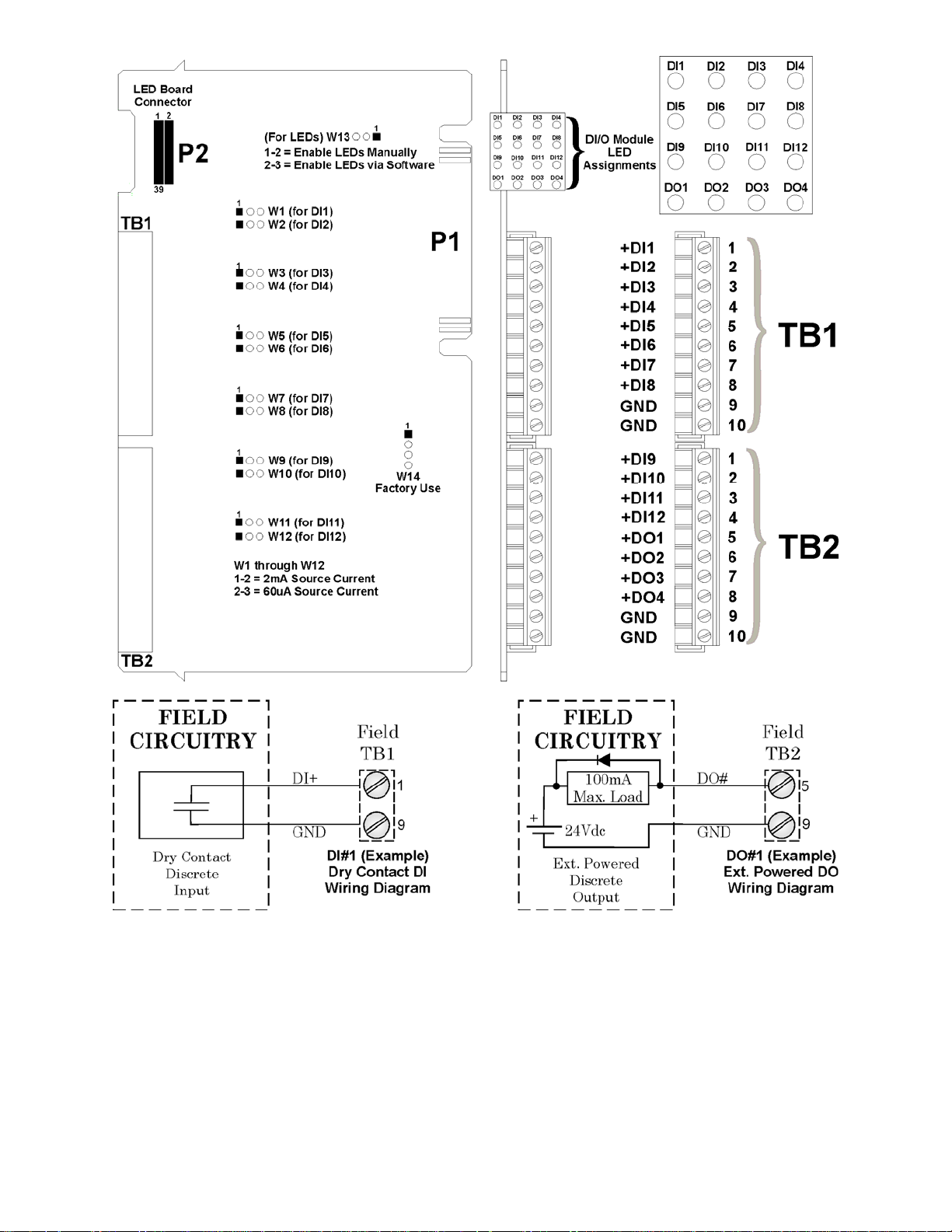
Figure 2-19 - Non-Isolated DI/O Module Configuration Diagram
2.3.4.5 Non-isolated Analog Input/Output & Analog Input Modules (see Figure 2-20)
Analog Input/Output Modules support six 4-20mA or 1-5 Vdc single ended analog inputs
and optionally, two independently configurable 4-20mA or 1-5 Vdc analog outputs. AI/O
Modules consists of an Analog Input/Output PCB with two 10-point Terminal Block
Assemblies (for local termination), 12 Configuration Jumpers and a Cover Assembly. The
AI/O Board mates with the Backplane PCB via a 36-pin gold plated card edge connector.
Analog Input Modules are identical to AI/O Modules but have a depopulated AO section.
CI-ControlWave EFM Installation & Operation / 2-31
Page 84

Each AI signal is channeled through signal conditioning circuitry (that provides a 2 Hertz
low pass filter), a transorb for surge suppression, multiplexer, and an A to D Converter
(ADC).
Figure 2-20 - Non-isolated AI/O & AI Module Configuration Diagram
2-32 / Installation & Operation CI-ControlWave EFM
Page 85

The Analog Output circuit consists of a 12-bit resolution Digital to Analog Converter (DAC),
a V to I circuit, and a V to V circuit. The 12-bit DAC dives the V to I circuitry. A scaling
circuit within the V to I circuit drives the V to V circuitry. V to I and V to V circuitry are
powered by an external power source.
A CPLD generates the control signals for the ADC, multiplexer, EEPROM, Bus Interface
2
and E
PROM that contains the calibration data.
2.3.4.5.1 Analog Input/Output Configurations
AI/O and AI Modules are provided with Configuration Jumpers that accommodate
configuration of each of the six Analog Inputs. Analog Input can be individually configured
for 1-5V or 4-20mA operation. Field wiring assignments are provided in Figure 2-20.
Note:
Cable shields associated with AI wiring should be connected to the ControlWave EFM’s
Chassis Ground. Multiple shield terminations will require a user supplied copper ground
bus. This ground bus must be connected to the ControlWave EFM’s Chassis Ground Lug
(using up to a #4 AWG wire size) and must accommodate a connection to a known good
Earth Ground (in lieu of a direct connection from the Ground Lug) and to all AI cable
shields. Shield wires should use an appropriate Terminal Lug and should be secured to
the copper bus via industry rugged hardware (screw/bolt, lockwasher and nuts).
Analog Input/Output Modules are provided with two Analog Outputs that are individually
jumper configurable for 1-5V or 4-20mA AO operation. The maximum external load that
can be connected to the 4-20mA output is 250 ohms (with an external 11V power source) or
650 ohms (with an external 24V power Source). The maximum external load current for the
1-5V output is 5mA (with an external 11 to 30 V power source). AO operation requires an
11 to 30Vdc power source connected to the VEXT terminal of the AI/O Module.
Table 2-9 - Analog Input/Output/Analog Input Module Jumper Assignments
Jumper Purpose Notes
JP1 - JP6 Configures AI1 through
AI6 (respectively)
JP7 AO1 Field Output Pins 1-2 installed = 4-20 mA AO
JP8 AO2 Field Output Pins 1-2 installed = 4-20 mA AO
JP9 AO1 Output Status Pins 1-2 installed = 1-5V AO
JP10 AO2 Output Status Pins 1-2 installed = 1-5V AO
J1 Configure ISP Connector Factory Use ONLY
W1 Program Serial EEPROM Factory Use ONLY
* Note: JP7 & JP9 Operation Must Match, i.e., both set for 1-5V or 4-20mA
JP8 & JP10 Operation Must Match, i.e., both set for 1-5V or 4-20mA
Pins 1-2 installed = 4-20 mA AI
Pins 2-3 installed = 1-5V AI
Pins 2-3 installed = 1-5V AO
Pins 2-3 installed = 1-5V AO
Pins 2-3 installed = 4-20 mA AO
Pins 2-3 installed = 4-20 mA AO
2.3.4.6 Non-isolated High Speed Counter Input Module (see Figure 2-21)
Non-isolated High Speed Counter Input (HSC) Modules provide a total of 4 inputs provided
with surge suppression bandwidth limiting and 20 microsecond (50kHz) filtering. HSC
Module inputs may be individually field configured with contact debounce circuitry enabled
or disabled and for 2mA or 200uA (low power) operation. When debounce circuitry is
enabled, spurious pulses caused by relay contact bounce are reduced with filters. HSC
CI-ControlWave EFM Installation & Operation / 2-33
Page 86

Modules consists of a High Speed Counter PCB with two 10-point Terminal Block
Assemblies (for local termination), 14 Configuration Jumpers, an LED Board with 4 Status
LEDs (one for each point) and a Cover Assembly. The HSC Board mates with the
Backplane PCB via a 36-pin gold plated card edge connector.
Figure 2-21 - Non Isolated HSC Module Configuration Diagram
High Speed Counter Input Modules contain conditioning circuitry consisting of a debounce
circuitry followed by a one shot pulse circuit that generates a 65 microsecond ±10% pulse
and limits the maximum frequency of an input signal to 15kHz. Field inputs can be driven
2-34 / Installation & Operation CI-ControlWave EFM
Page 87

signals, or relay contacts. A serial EEPROM contains HSC Board serialization data. Each
input of the HSCI Module is configured as a 16-bit high-speed counter.
2.3.4.6.1 High Speed Counter Configurations
HSC Modules provide a total of 4 HSC inputs with surge protection. HSC Module Configuration Jumpers W1 through W14 must be set per Table 2-10.
Table 2-10 - Non Isolated High Speed Counter Module Jumper Assignments
Jumper Purpose Notes
W1 - W4 Configures HSC1 through
HSC4 (respectively)
W5 Program Serial EEPROM Factory Use ONLY
W6 LED Enable/Disable Pins 1-2 installed = Enables LEDs Manually
W7 & W8 HSC1 Current Control Pins 1-2 installed = for additional 2mA load
W9 & W10 HSC2 Current Control Pins 1-2 installed = for additional 2mA load
W11 & W12 HSC3 Current Control Pins 1-2 installed = for additional 2mA load
W13 & W14 HSC4 Current Control Pins 1-2 installed = for additional 2mA load
Pins 1-2 installed = Enables HSC Debounce
Pins 2-3 installed = Disabled HSC Debounce
Pins 2-3 installed = Enable LEDs via software
Pins 2-3 installed = 200uA Source no 2mA load
Pins 2-3 installed = 200uA Source no 2mA load
Pins 2-3 installed = 200uA Source no 2mA load
Pins 2-3 installed = 200uA Source no 2mA load
Field wiring assignments are provided in Figure 2-21.
2.3.4.7 Non-isolated Mixed I/O Module (see Figures 2-22 & 2-23)
Non-isolated Mixed I/O Modules provide a total of 6 individually field configurable Digital
Inputs/Outputs, 4 Analog Inputs, 2 High Speed Counter Inputs and 1 optional Analog
Output. I/O circuitry is similar to those utilized on the I/O Modules discussed in sections
2.3.4.4 through 2.3.4.6.
Surge Suppression and signal conditioning is provided for each DI. DO circuits consist of an
open drain MOSFETs and Surge Suppression. Mixed I/O Modules provide internally
sourced DI operation for Dry Contacts pulled internally to 3.3Vdc when the field input is
open. Each DI is protected with a surge suppressor. DI filtering is 15 milliseconds. DOs are
composed of open drain MOSFETs and surge suppressors.
Mixed I/O Module AIs are independently configurable for 4-20mA or 1-5 Vdc single ended
operation. Each AI signal is channeled through signal conditioning circuitry (that provides
a 2 Hertz low pass filter), a transorb for surge suppression, multiplexer, and an A-to-D
Converter (ADC).
Non-isolated Mixed I/O Modules support a total of 2 HSC inputs provided with surge
suppression, bandwidth limiting and 20 microsecond (50kHz) filtering. HSC inputs may be
individually field configured with contact debounce circuitry enabled or disabled and for
2mA or 200uA (low power) operation. HSCs are supported by signal conditioning circuitry
consisting of a debounce circuit followed by a one shot pulse circuit that generates a 65
microsecond ±10% pulse and limits the maximum frequency of an input signal to 15kHz.
Field inputs can be driven signals, or relay contacts. Each input of the HSCI Module is
configured as a 16-bit high-speed counter.
CI-ControlWave EFM Installation & Operation / 2-35
Page 88

Figure 2-22 - Mixed I/O Module Wiring Diagram
Mixed I/O Modules optionally support one externally powered (VEXT = 11 to 30Vdc) analog
output. AO Circuitry consists of a 12-bit resolution Digital to Analog Converter (DAC), a V
to I circuit, and a V to V circuit. The 12-bit DAC drives the V to I circuitry. A scaling circuit
within the V to I circuit drives the V to V circuitry. V to I and V to V circuitry are powered
by an external power source.
2-36 / Installation & Operation CI-ControlWave EFM
Page 89
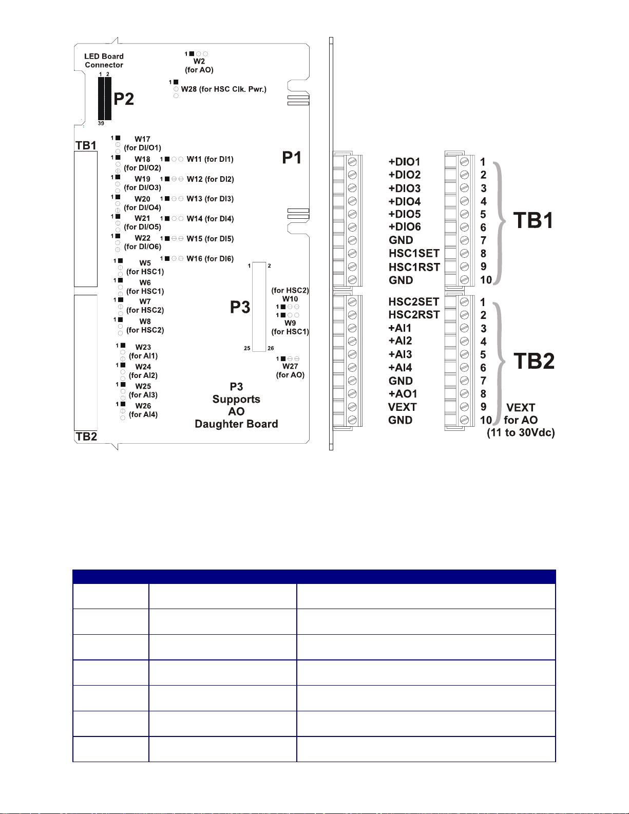
Figure 2-23 - Non Isolated Mixed I/O Module Configuration Diagram
2.3.4.7.1 Mixed I/O Module Configurations
Mixed I/O Module Configuration Jumpers W1 through W28 must be set per Table 2-11.
Table 2-11 - Non Isolated Mixed I/O Module Jumper Assignments
Jumper Purpose Notes
W1*
W2
W5 & W6 HSC1 Current Control
W7 & W8 HSC2 Current Control
W9 & W10
W11 - W16
W17 - W22
Configures optional AO for
Voltage or Current Output
Configures optional AO for
Voltage or Current Output
Configures HSC1 and HSC2
Debounce (respectively)
Configures DI1 through DI6
Current (respectively)
DI/O1 through DI/O6 Point
Selection (respectively)
Pins 1-2 installed = AO set for Current Output
Pins 2-3 installed = AO set for Voltage Output
Pins 1-2 installed = AO set for Voltage Output
Pins 2-3 installed = AO set for Current Output
Pins 1-2 installed = for additional 2mA load
Pins 2-3 installed = 200uA Source no 2mA load
Pins 1-2 installed = for additional 2mA load
Pins 2-3 installed = 200uA Source no 2mA load
Pins 1-2 installed = Enables HSC Debounce
Pins 2-3 installed = Disabled HSC Debounce
Pins 1-2 installed = 2mA Source Current
Pins 2-3 installed = 60uA Source Current
Pins 1-2 installed = Digital Input Operation
Pins 2-3 installed = Digital Output Operation
CI-ControlWave EFM Installation & Operation / 2-37
Page 90

Table 2-11 - Non Isolated Mixed I/O Module Jumper Assignments (Continued)
Jumper Purpose Notes
W23 - W26
W27
W28 HSC Circuitry Enable
* = W1 located on optional AO Daughter Board
Configures AI1 through AI4
(respectively)
AO Voltage Selection
Set W27 Pins 2-3
ALWAYS
Pins 1-2 installed = 4-20mA AI (250 ohm resistor
in)
Pins 2-3 installed = 1-5V AI
Pins 1-2 installed = N/A
Pins 2-3 installed = External Field Voltage (TB2-9)
Pins 1-2 installed = HSC Circuit Enable (Powered)
Pins 2-3 installed = HSC Circuit Disabled
2.3.5 RTD Wiring
A 3-wire RTD may be provided with the ControlWave EFM. Connector TB2 on the System
Controller Module accommodates a removable three-wire Terminal Block (similar to TB1).
This connector accommodates a 100-ohm platinum bulb using the DIN 43760 curve.
ControlWave EFM’s utilize the common three-wire configuration. In this configuration,
the Return lead connects to RTD- and the two junction leads (Sense and Excitation),
connect to RTD+ and RTD EXC. Connection between the RTD and System Controller
Module is wired as follows:
Table 2-12 - RTD Connections to System Controller Connector TB2
TB2 Pin
1 RTD EXC Excitation
2 RTD+ Sense
3 RTD- Return
Never ground the RTD Cable Shield at both ends or allow it to come in contact with metallic or conductive conduit as multiple ground paths could result and cause RTD input errors.
Signal Function
Figure 2-24 - 3-Wire RTD Temperature Input Wiring
To install the RTD Probe, screw the Fitting Body into the thermowell with a 7/8”open-end
wrench. While applying pressure against the sheath to force the Tip of the RTD Probe into
the bottom of the thermowell (so that the Probe Tip is in contact with the thermowell),
tighten the Nut (9/16” open-end wrench) against the 7/8” Fitting Body (see Figure 2-25).
2-38 / Installation & Operation CI-ControlWave EFM
Page 91

Figure 2-25 - RTD Probe Installation/Removal Diagram
2.3.6 21V Power Supply Option
21V Power Supplies are mainly used in conjunction with Temperature and Pressure
Transmitters which require a higher than +12V but lower than +21.4V (±.8V) input supply
to operate (such as Series 3508 Transmitters).
Figure 2-26 - 21V Power Supply Board
21V Power Supply Boards contain two terminal blocks that accommodate power connections between the ControlWave EFM and remote transmitters. TB1 is a three-position
terminal block that provides input power connection from the Power Distribution Board.
Four-position Terminal Block (TB2) provides +21V power and ground to external devices
such as Series 3508 Transmitters.
CI-ControlWave EFM Installation & Operation / 2-39
Page 92

Table 2-13 - 21V Power Supply Board Terminal Designations
21VPS
TB#
TB1-1 +12VIN TB3-1 N/A
TB1-2 12VGND TB3-2 N/A
TB1-3 CHASSISGND N/A N/A
TB2-1 +21V N/A XMTR1+
TB2-2 21VGND N/A XMTR1TB2-3 +21V N/A XMTR2+
TB2-4 21VGND N/A XMTR2-
21VPS
TB NAME
CONNECTION
to PDB.
CONNECTION
to XMTR.
2.3.7 Digital to Relay I/O Board Option
Digital to Relay I/O Boards except up to two discrete input signals from an open drain
MOSFET device and convert them to Form C relay output signals using Solid State Relay
(SSR) logic. The minimum current load will be 100mA. Figure 2-27 provides a component
view of the Digital to Relay I/O Board.
Each ControlWave EFM Discrete Output is converted to a Form C relay output signal
which can be configured for opposite or identical state conditions, i.e., both Normally Open
(NO) or Normally Closed (NC) or one Normally open with the other Normally Closed.
Figure 2-27 - Digital to Relay I/O Board
2.3.7.1 Digital to Relay I/O Board Jumper Settings
The Digital To Relay I/O Board contains ten (10) Jumpers which allow the user to configure
contacts for Normally Open/Normally Closed states. Contacts associated with each of the
Form C Relays may be configured for identical or opposite states. Note: Jumper Pairs
W3/W5, W4/W6, W7/W9 and W8/W10 must be set in opposite states.
2-40 / Installation & Operation CI-ControlWave EFM
Page 93

The commons associated with each form C Relay (R0COM and R1COM) have the option of
being tied to the ControlWave EFM Power Ground or to a floating Ground. Jumper W1 is
associated with Outputs R0A and R0B and W2 is associated with outputs R1A and R1B.
When Jumper W1 is installed the common (C) associated with Outputs R0A and R0B is tied
to ControlWave EFM Power ground; when Jumper W1 is not installed, the common will
be floating. When Jumper W2 is installed the common (C) associated with Outputs R1A and
R1B is tied ControlWave EFM Power ground; when Jumper W2 is not installed, the
common will be floating.
Table 2-14 - Jumper Settings versus Form C Relay Output States
JUMPERS
W3/W5
IN/OUT NO IN/OUT NO IN/OUT NO IN/OUT NO
OUT/IN NC OUT/IN NC OUT/IN NC OUT/IN NC
R0A
STATE
JUMPERS
W4/46
R0B
STATE
JUMPERS
W7/W9
R1A
STATE
JUMPERS
W7/W9
R1B
STATE
Table 2-13 provides the relationship between Jumper settings and Form C Relay Outputs.
Table 2-15 - Digital To Relay I/O Board Connections to J1/P1
J1 Pin Signal Function Wiring Connections
1 R1B Relay 1 Output B To Field
2 R1A Relay 1 Output A To Field
3 R1COM Relay 1 Common To Field (See W2)
4 CHASSIS GND Chassis Ground CWMICRO Chassis Gnd. Lug
5 R0COM Relay 0 Common To Field (See W1 - Section 1.1.1)
6 ROB Relay 0 Output B To Field
7 ROA Relay 0 Output A To Field
8 - - -
9 POWER GND Power Ground
10 POWER - DC Power - 6/12 Vdc
11 DOUT0 Discrete Output 0
12 DOUT1 Discrete Output 1
Pwr. Dist. Bd.
TB4 Pin 2 (Black Wire)
Pwr. Dist. Bd.
TB4 Pin 1 (Red Wire)
DI/O Module TB2-5 - TB2-8 or
Mixed I/O Module TB1-1 - TB1-6 (Yellow Wire)
DI/O Module TB2-6 - TB2-8 or
Mixed I/O Module TB1-2 - TB1-6 (Orange
Wire)
The DI/DO Module and the Mixed I/O Module provide independently firmware controlled
open drain outputs, which can be used for control or signaling functions (DI/DO Modules
provide up to four DO while the Mixed I/O Module provides up to 6 DO). Each output is
wired to the source terminal of an N Channel MOSFET capable of switching up to 16 Volts
at up to 100mA. When closed, the FET shorts the output to ground with resistance of .5
Ohms or less. These outputs are protected by 16V Transorbs. Since these outputs are not
isolated, caution must be exercised to ensure that the load current does not affect operation
of the ControlWave EFM or related devices.
Two of these outputs may be wired to field circuitry via the Digital to Relay I/O Board
option (see Figure 2-28). Table 2-15 provides the wiring connections for the DI/O Module or
the Mixed I/O Module and the Digital to Relay I/O Board.
CI-ControlWave EFM Installation & Operation / 2-41
Page 94

Figure 2-28 - Digital to Relay I/O Board Wiring Diagram
2.3.8 Connection to a Model 3808 Transmitter
A Model 3808 Transmitter (Digital) can be interfaced to a ControlWave EFM via either
an RS-232 or an RS-485 communication scheme. Communication schemes and cable
lengths are determined the type of communication port utilized. In general RS-232
communications are utilized when the Model 3808 Transmitter is situated within 25 feet of
the ControlWave EFM, i.e., for local communications. Communications can be achieved
with transmitters up to 4000 feet away (remote communications) via the RS-485 scheme.
Figure 2-29 - Model 3808 Transmitter to ControlWave EFM
RS-232 Comm. Cable
2-42 / Installation & Operation CI-ControlWave EFM
Page 95

Note: For Loopback & Termination Control:
Use SW3 on CPU Module to configure COM3.
Use SW1 on ECOM Module to configure COM5 or COM9.
Figure 2-30 - Model 3808 Transmitter to ControlWave EFM
RS-485 Comm. Cable
Figure 2-31 - ControlWave EFM to 3808s - RS-485 Network Diagram
CI-ControlWave EFM Installation & Operation / 2-43
Page 96

Figures 2-29 and 2-30 detail the RS-232 and RS-485 wiring connections required between
the ControlWave EFM and the Model 3808 Transmitter.
Up to eight (8) Model 3808 Transmitters can be connected to a ControlWave EFM via a
half duplex RS-485 Network. An illustration of this network is provided in Figure 2-31.
2.3.9 Power Wiring & Distribution
Power may be provided from a rechargeable 12V lead-acid battery (used in conjunction with
a 30W Solar Panel (with a built-in Regulator) or a user supplied external bulk dc power
supply (4.5 to 16Vdc). A Power Distribution Board is required if the unit is equipped with
an external radio/modem, or 21Vdc Power Supply Board, or Digital to Relay I/O Board (or
any combination of them) and bulk power is supplied from an external bulk dc source.
Figure 2-32 - Pwr. Distribution Bd. and Other Options - Snap Track Mounting
ControlWave EFM Terminal Blocks utilize compression-type terminals that accommodate
up to #14 AWG wire. A connection is made by inserting the wire’s bared end (1/4” max) into
the clamp adjacent to the screw and then securing the screw. The wire should be inserted
fully so that no bare wires are exposed to cause shorts. If using standard wire, tin the bare
end with solder to prevent flattening and improve conductivity. Allow some slack in the
wires when making connections. The slack makes the connections more manageable and
helps to minimize mechanical strain on the terminal blocks.
2-44 / Installation & Operation CI-ControlWave EFM
Page 97

Power Distribution Boards are provided with six (6) Terminal Connector Blocks that
function as follows:
TB1 - Primary Power Input: (three-conductor) (from user supplied bulk power source)
TB1-1 = Power+ (Pos. input)
TB1-2 = Power– (Neg. input)
TB1-3 = Chassis (GND)
TB2 - Main Power Output 1: (two-conductor) (to SCM Power Connector TB1)
TB2-1 = PWR1+ to TB1-1 on SCM (+VIN)
TB2-2 = PWR1– to TB1-2 on SCM (–VIN)
TB3 - Main Power Output 2: (two-conductor) (to 21V PS Board Connector TB1)
TB3-1 = PWR2+ to TB1-1 on 21VPS (+VIN)
TB3-2 = PWR2– to TB1-2 on 21VPS (GND)
TB4 - Fused Power Output 1: (two-conductor) (to Digital to Relay I/O Board Connector J1)
TB4-1 = FPWR1+ to J1-10 on D-to-R I/O Bd. (PWR+)
TB4-2 = FPWR1– to J1-9 on D-to-R I/O Bd. (PWR GND)
TB5 - Fused Power Output 2: (two-conductor) (to External Modem/Radio Pwr. Connector)
TB5-1 = FPWR2+ to Radio/Modem Power+
TB5-2 = FPWR2– to Radio/Modem Power– (PWR GND)
TB6 - Fused Power Output 3: (two-conductor) (optional use - similar to TB5)
TB6-1 = FPWR3+ to Radio/Modem Power+
TB6-2 = FPWR3– to Radio/Modem Power– (PWR GND)
Note: F1 is rated at 1.5A and protects the Solar Panel Regulator Circuitry. Fuse
F3 is rated at .5A and protects Fused Power Output 1. F1 and F3 are provided for
Class I, Div. 1 Hazardous Location use Only.
Figure 2-33 - Power Distribution Board
2.3.9.1 Bulk Power Supply Current Requirements
ControlWave EFM electronic flow meters are equipped with a System Controller Module
that accepts either 6Vdc or 12Vdc Bulk Power input. The maximum current required for a
particular ControlWave EFM can be estimated as follows:
CI-ControlWave EFM Installation & Operation / 2-45
Page 98

Bulk +6/12Vdc Supply Current = CPU* + Sum of all ECOM Modules, I/O Modules, optional
Boards & Optional External Modem/Radio
This summation will accommodate steady state current draw. Table 2-16 provides detailed
steady state power current requirements for each ControlWave EFM Base Assembly
module. Note: In the case of an external modem/radio, the unit’s manufacturer provides
power consumption specifications. Power requirements for the optional Digital to Relay I/O
Board, 21V Power Supply Board and the Battery Charger/Power Manager Board are
provided in Sections 4.5, 4.6 and 4.7 (respectively) of this manual.
Table 2-16 - ControlWave EFM Base Assembly Power Requirements
COMPONENTS BULK 12Vdc Supply BULK 6Vdc Supply
CPU* = CPU + SCM + Backplane 8.6mA 14mA
Non-Isolated AI/O Module 2.8mA + (47.2mA - VEXT) 5.6mA + (47.2mA - VEXT)
Non-Isolated DI/O Module 12mA 24mA
Non-Isolated HSC Module 5mA 10mA
Non-Isolated Mixed I/O Module
(with optional AO Board)
ECOM Module
(without Modem/Radio)
ECOM Module
(with MultiTech Modem)
ECOM Module
(with MDS Radio)
ECOM Module
(with Modem & MDS Radio)
ECOM Module
(with FreeWave Radio)
ECOM Module
(with Modem & FreeWave Radio)
Note: Current consumption provided in Table 2-15 is based on the standard
Electronic Flow Computer application load.
16.67mA + (24.3mA - VEXT) 34mA + (24.3mA - VEXT)
22mA 45mA
56mA 112mA
277mA 555mA
311mA 622mA
272mA 545mA
306mA 612mA
2.3.9.2 Power Wiring
DC Power is interconnected to the System Controller Module (SCM) on Connector TB1. One
Bulk DC supply can be connected to the ControlWave EFM SCM. The Bulk DC supply
(nominally +6Vdc or +12Vdc) connected to TB1-1 (+VIN on SCM) is converted, regulated
and filtered by the SCM to produce +3.3Vdc. This SCM circuit is fused at 1A. The operating
range of the SCM is +4.5/4.9Vdc to +16.0Vdc (nominal +6Vdc input source) or +9.6/10.3Vdc
to +16.0Vdc (nominal +12Vdc input source).
SCM Connector TB1 provides 3 input connections for bulk power as follows:
TB1-1 = (+VIN) (+4.5/4.9V to +16V dc for +6V bulk) (+9.6/10.3V to +16V dc for +12V bulk)
TB1-2 = (-VIN) (Supply Ground)
TB1-3 = Chassis Ground - CHASSIS
Figure 2-34 - SCM (TB1) Typical Wiring Scheme
2-46 / Installation & Operation CI-ControlWave EFM
Page 99

2.3.9.3 Mounting an Optional Solar Panel
s
A
A
Solar Panels (used to charge the rechargeable lead acid batteries) are to be mounted to a 2”
to 2-3/8” pipe as illustrated in Figure 2-35. Muffler (Pipe) Clamps, utilized for this purpose,
are secured via four 1/4-20 nuts and washers.
E
A
C
NOTE 1: To Attach item C to item D:
Slide two bolts (A) through the top and bottom
Solar Panel (Centered) Channel Holes. Affix item
C to item D via 2 sets of item A hardw are as
follows: Flat Washer, Lock Washer & Hex Nut
(Max. Torque = 120 Inch-Pounds).
E
A
A
D
B
B
Note 2: Item D slot
accommodate Tilt
Angle Adjustment.
A
B
A
E
C
Adjustable
Tilt Angle
D
Vertical
B
Pole
A - 6 places consists of
the following hardware:
D
A
A
A
A
B
C
5/16-18 x .75 Hex Hd. Bolt
5/16 Flat Washer
5/16 Spring Lock Washer
5/16-18 Hex Nut
B - 2 places:
2-3/8 U-Clamp Assembly
C - Adjustable Angle Bracket
(Attaches to Solar Panel)
D - Pole Mounting Bracket
E - 30 or 40 Watt Solar Panel
Figure 2-35 - 30/40 Watt Solar Panel Mounting Diagram
2.3.9.3.1 Swivel (Directional Facing)
Solar Panels used in the Northern Hemisphere should face due south (not magnetic south)
while those used in the southern hemisphere should face due north (not magnetic north).
CI-ControlWave EFM Installation & Operation / 2-47
Page 100

2.3.9.3.2 Tilt Angle
30/40 Watt Solar Panel Systems (see Figure 2-35) have adjustable tilt angles. Table 2-17
shows the angle (from horizontal) at which the Solar Panel should be installed in order to
maximize annual energy output. At most latitudes, performance can be improved by less of
an angle during the summer and more of an angle during the winter.
Table 2-17 - Solar Panel Tilt Angle for 40 Watt & 30 Watt Solar Panels
LATITUDE INSTALLATION ANGLE
0-4° 10° from Horizontal
5-20° Add 5° to the Local Latitude
21-45° Add 10° to the Local Latitude
46-65° Add 15° to the Local Latitude
66-75° 80° from Horizontal
2.3.9.4 Installing the Rechargeable Battery and Solar Panel Harness
The Rechargeable Sealed Lead-acid Battery must be removed from its shipping carton and
installed on its mounting bracket within the enclosure as illustrated in Figure 2-36.
Figure 2-36 - Enclosure with Sealed Lead-acid Battery Installed
2-48 / Installation & Operation CI-ControlWave EFM
 Loading...