

Page 1
CFA-3000
Ion Selective Electrode (ISE) Analyzer
Instruction Manual
PN 51CFA3000ISE/rev.F
December 2013
Page 2
ESSENTIAL INSTRUCTIONS
READ THIS PAGE BEFORE PROCEEDING!
Your purchase from Rosemount Analytical, Inc. has
resulted in one of the finest instruments available for
your particular application. These instruments have
been designed, and tested to meet many national
and international standards. Experience indicates
that its performance is directly related to the quality
of the installation and knowledge of the user in oper
ating and maintaining the instrument. To ensure their
continued operation to the design specifications, per
sonnel should read this manual thoroughly before
proceeding with installation, commissioning, opera
tion, and maintenance of this instrument. If this
equipment is used in a manner not specified by the
manufacturer, the protection provided by it against
hazards may be impaired.
• Failure to follow the proper instructions may cause
any one of the following situations to occur: Loss
of life; personal injury; property damage; damage
to this instrument; and warranty invalidation.
• Ensure that you have received the correct model
and options from your purchase order. Verify that
this manual covers your model and options. If not,
call 18008548257 or 9497578500 to request
correct manual.
• For clarification of instructions, contact your
Rosemount representative.
• Follow all warnings, cautions, and instructions
marked on and supplied with the product.
• Use only qualified personnel to install, operate,
update, program and maintain the product.
• Educate your personnel in the proper installation,
operation, and maintenance of the product.
• Install equipment as specified in the Installation
section of this manual. Follow appropriate local
and national codes. Only connect the product to
electrical and pressure sources specified in this
manual.
• Use only factory documented components for
repair. Tampering or unauthorized substitution of
parts and procedures can affect the performance
and cause unsafe operation of your process.
• All equipment doors must be closed and protective
covers must be in place unless qualified personnel
are performing maintenance.
• If this equipment is used in a manner not specified
by the manufacturer, the protection provided by it
against hazards may be impaired.
WARNINGS
RISK OF ELECTRICAL SHOCK
Equipment protected throughout by double insulation.
• Installation of cable connections and servicing of this
product require access to shock hazard voltage levels.
• Main power and relay contacts wired to separate power
source must be disconnected before servicing.
• Do not operate or energize instrument with case open!
• Signal wiring connected in this box must be rated at least
240 V.
• Nonmetallic cable strain reliefs do not provide grounding
between conduit connections! Use grounding type bush
ings and jumper wires.
• Unused cable conduit entries must be securely sealed by
nonflammable closures to provide enclosure integrity in
compliance with personal safety and environmental protec
tion requirements. Unused conduit openings must be
sealed with NEMA 4X or IP65 conduit plugs to maintain
the ingress protection rating (NEMA 4X).
• Electrical installation must be in accordance with the
National Electrical Code (ANSI/NFPA70) and/or any
other applicable national or local codes.
• Operate only with front and rear panels fastened and in
place over terminal area.
• Safety and performance require that this instrument be
connected and properly grounded through a threewire
power source.
• Proper relay use and configuration is the responsibility of
the user.
CAUTION
This product generates, uses, and can radiate radio frequency
energy and thus can cause radio communication interference.
Improper installation, or operation, may increase such interfer
ence. As temporarily permitted by regulation, this unit has not
been tested for compliance within the limits of Class A comput
ing devices, pursuant to Subpart J of Part 15, of FCC Rules,
which are designed to provide reasonable protection against
such interference. Operation of this equipment in a residential
area may cause interference, in which case the user at his
own expense, will be required to take whatever measures may
be required to correct the interference.
WARNING
This product is not intended for use in the light
industrial, residential or commercial environments
per the instrument’s certification to EN500812.
Emerson Process Management
2400 Barranca Parkway
Irvine, CA 92606 USA
Tel: (949) 7578500
Fax: (949) 4747250
http://www.rosemountanalytical.com
© Rosemount Analytical Inc. 2012
Page 3

CFA3000 ISE Analyzer TABLE OF CONTENTS
Instruction Manual
1.0 INTRODUCTION...........................................................................................................................1
1.1 Thoroughly Read This Manual......................................................................................................2
1.2 Analyzer Benefits...........................................................................................................................2
1.3 WARNING Electrical Shock Hazard..........................................................................................3
2.0 INSTALLING THE ANALYZER....................................................................................................4
2.1 Unpack Parts .................................................................................................................................4
2.2 Mount Main Cabinet ......................................................................................................................6
2.3 Mount Reagent Cabinet ................................................................................................................6
2.4 Install Waste Tube .........................................................................................................................8
2.5 Mount Overflow Sampling Assembly............................................................................................8
2.6 Prepare Electrical Connections...................................................................................................10
2.7 Install Valve Pump Assembly ......................................................................................................11
2.8 Prepare Reagent Containers ......................................................................................................13
3.0 OPERATING THE ANALYZER ..................................................................................................14
3.1 Operational Overview..................................................................................................................14
3.2 Check Sample Stream ................................................................................................................15
3.2.1 Check Fluidics .............................................................................................................................15
3.2.2 Check Reagents..........................................................................................................................15
3.2.3 Turn On Power ............................................................................................................................15
3.2.4 Test Valve Pump Operation ........................................................................................................16
3.2.5 Set Up Stream Parameters ........................................................................................................20
3.3 Set Reagent Supply Time ..........................................................................................................22
3.4 Set Scaling Outputs.....................................................................................................................22
3.4.1 Record mV ................................................................................................................................23
3.4.2 Initiate Auto Calibration ..............................................................................................................23
3.5 Process a Grab Sample .............................................................................................................24
3.6 Manually Sample a Particular Stream .......................................................................................25
3.7 Shutdown ................................................................................................................................25
3.8 Quick Start ................................................................................................................................26
4.0 MAINTAINING THE ANALYZER ...............................................................................................27
4.1 Analyzer Equipment ....................................................................................................................27
5.0 TROUBLESHOOTING PROCEDURES....................................................................................28
5.1 Troubleshooting Chart.................................................................................................................28
5.2 Test Functions .............................................................................................................................29
6.0 REPAIR PROCEDURES ............................................................................................................31
6.1 Replace Valve Pump Assembly..................................................................................................31
6.2 Replace Circuit Boards ...............................................................................................................32
6.3 Replace Fuses.............................................................................................................................33
6.4 Replace ISE Components...........................................................................................................33
7.0 INSTRUMENT DESCRIPTION ..................................................................................................34
7.1 Analyzer Front View ....................................................................................................................34
7.1.1 Main Cabinet ...............................................................................................................................34
7.1.2 Reagent Cabinet .........................................................................................................................34
7.2 Keypad Panel ..............................................................................................................................36
7.3 Card Cage 41 ............................................................................................................................37
7.3.1 Card Cage and Door ...................................................................................................................37
7.3.2 CPU Board 41 ............................................................................................................................37
7.3.3 Analog Board...............................................................................................................................37
7.3.4 Valve Board 41 ............................................................................................................................37
7.3.5 Power Supply Board ...................................................................................................................37
i
CFA3000 ISE Analyzer
TABLE OF CONTENTS
Page 4

ii
CFA3000 ISE Analyzer TABLE OF CONTENTS
Instruction Manual
7.3.6 Analog Board DIP Switches........................................................................................................39
7.4 Rear of Main Cabinet ..................................................................................................................40
7.5 Valve Pump Assembly.................................................................................................................41
7.6 Interface Ports .............................................................................................................................42
7.7 Relay Output Option....................................................................................................................42
7.8 MultiOutput Board ......................................................................................................................42
7.9 Overflow Sampling Assemblies ..................................................................................................43
8.0 ADDITIONAL FEATURES .........................................................................................................45
8.1 Chart Recorders and Data Loggers............................................................................................45
8.2 Computer Interface......................................................................................................................48
8.2.1 Data Output Format.....................................................................................................................48
8.2.2 Data Configuration.......................................................................................................................48
8.2.3 RS232C Function Commands...................................................................................................48
8.2.4 Initiating RS232C Communications to Computer .....................................................................49
8.2.5 Printer Interface ...........................................................................................................................51
8.2.6 Set Printer Internal Clock ............................................................................................................51
Appendix A. CHEMISTRIES..................................................................................................................52
Appendix B. SPECIFICATIONS ........................................................................................................5354
Appendix C. POWER INTERCONNECT DESCRIPTION .....................................................................55
Appendix D. BYPASS FOR CALIBRATION..........................................................................................56
Appendix E. KEYPAD HELP SHEETS .................................................................................................57
ORDERING INFORMATION ....................................................................................................................63
WARRANTY ................................................................................................................................64
9.0 RETURN OF MATERIAL............................................................................................................65
TABLE OF CONTENTS (CON’T)
Page 5

iii
TABLE OF CONTENTS (CON’T)
CFA3000 ISE Analyzer TABLE OF CONTENTS
Instruction Manual
LIST OF FIGURES
Figure 21 Opened Assembled Cabinet....................................................................................5
Figure 22 Mounting Main and Reagent Cabinets ....................................................................7
Figure 23 Attaching Grounding Strap.......................................................................................7
Figure 24a Singlestream Overflow Sampling Assembly...........................................................9
Figure 24b Multistream Overflow Sampling Assembly.............................................................9
Figure 25 Input/Output Panel..................................................................................................11
Figure 26 Valve Pump Assembly............................................................................................12
Figure 27 Pump Connectors ..................................................................................................12
Figure 28 Sample Bottle Placement in Cabinet (for all methods; colors refer to
reagent straw colors)..............................................................................................13
Figure 31 Simple Block Diagram............................................................................................14
Figure 32 Numbered Positions on a SingleStream Keypad.................................................17
Figure 33 Valve Pump LED Designations..............................................................................19
Figure 34 Logic Flow for Singlestream Parameter Definition...............................................20
Figure 35 Logic Flow for Multistream Parameter Definition .................................................21
Figure 61 Remove Valve Pump Assembly.............................................................................31
Figure 62 Card Cage ..............................................................................................................32
Figure 63 ISE Reaction Cell Assembly, Electrodes ...............................................................33
Figure 71 Analyzer Front View ...............................................................................................35
Figure 72 Card Cage and Boards ..........................................................................................38
Figure 73 Analog Board DIP Switches (with #3 set in OFF position for multi..........................
stream analyzer)....................................................................................................39
Figure 74 Electrical Wiring and Components in Rear Cabinet..............................................40
Figure 75 Valve Pump Assembly............................................................................................41
Figure 76 Interface Ports ........................................................................................................42
Figure 77 "D" Connector for Relay Output.............................................................................42
Figure 78 SingleStream Overflow Sampling Assembly ........................................................43
Figure 79 Multistream Overflow Sampling Assembly (threestream option)........................44
Figure 81 Input/Output Panel .................................................................................................45
Figure 82 Typical Trace Recording with Calibration of Single Stream System.....................46
Figure 83 Typical Stream Trace Recording with Calibration of Multistream
System....................................................................................................................47
Figure 84 Numbered Positions on a SingleStream Keypad................................................49
Figure D1 Calibration Bypass Wiring......................................................................................56
Figure E1 Keypad Panel for Single Stream Option................................................................57
Figure E2 Number Positions on a SingleStream Keypad....................................................57
Figure E3 Keypad Panel for Multistream Option...................................................................60
Page 6

iv
CFA3000 ISE Analyzer TABLE OF CONTENTS
Instruction Manual
TABLE OF CONTENTS (CON’T)
LIST OF TABLES
Table 51 Troubleshooting Chart.....................................................................................28
Table 52 Test Functions .................................................................................................29
Table 71 Main Cabinet Parts..........................................................................................34
Table 72 Reagent Cabinet Parts ....................................................................................34
Table 73 Buttons/LED Functions ...................................................................................36
Table 74 Card Cage Parts .............................................................................................37
Table 75 CPU Board Components.................................................................................37
Table 76 Analog Board Components .............................................................................37
Table 77 Valve Board Components ...............................................................................37
Table 78 Power Supply Board Components ..................................................................37
Table 79 Analog Board DIP Switch Positions ................................................................39
Table 710 Back Cabinet Parts .........................................................................................40
Table 711 Valve Pump Parts............................................................................................41
Table 712 Interface Ports.................................................................................................42
Table 713 Relay Output Option Pin Assignments ............................................................42
Table 714 Multioutput Pin Assignments on “D” Connector .............................................42
Table 715 Overflow Sampling Assembly Parts ................................................................43
Table 81 Stream Identification Blips (SIBs)....................................................................45
Table 82 Normal Data Output Format............................................................................48
Table 83 Data Configuration ..........................................................................................48
Table 84 RS232C Pin Configuration .............................................................................48
Table 85 RS232C Commands ......................................................................................50
Table 86 Printer Port Pin Configuration .........................................................................51
Table E1 Singlestream Keypad Help Sheet.............................................................5859
Table E2 Multistream Keypad Help Sheet ...............................................................6062
Table E3 Replacement Parts .........………..……………………………………….…….63
Page 7

1
CFA3000 MANUAL SECTION 1
INTRODUCTION
SECTION 1
INTRODUCTION
The Rosemount Analytical CFA3000 Series analyzers are designed for minimum maintenance and maximum
reliability. The touch of a button starts the microprocessorcontrolled program, calibrates the analyzer, keeps it
calibrated, and reports results directly unattended for months at a time. Maintenance is simplified by a modular
design with special fittings, labeled tubing, and colorcoded components.
The CFA3000 Series includes analyzers for parameters commonly measured using Ion Selective Electrode (ISE)
technology including sodium, fluoride and chloride. Sample concentration is clearly indicated on the digital display
panel, and output signals are provided to drive recorders, alarms, or other external devices such as printers or
computers. The specific chemistry of your individual analyzer is discussed in Appendix A, Chemistries, or in an
accompanying method sheet..
Your purchase from Rosemount Analytical provides you with one of the finest instruments available for your
particular application. These instruments have been designed and tested to meet many national and international
standards. Experience indicates that its performance is directly related to the quality of the installation and knowl
edge of the user in operating and maintaining the instrument.
Page 8

2
CFA3000 ISE Analyzer
Instruction Manual
1.1 Thoroughly Read This Manual
This instruction manual describes installation, operation, and maintenance of the CFA3000 ISE Analyzer. To
ensure continued operation to the design specifications, personnel should read this manual thoroughly before
proceeding with installation, operation, or maintenance of the analyzer.
• Ensure that you have received the correct model and options from your purchase order. Verify that this
manual covers your model and options. If not, call: 18008548257 or 9497578500 to request the correct
manual.
• For any inquiries about your analyzer, contact your Rosemount Analytical representative.
• Failure to follow the documented instructions may cause any one of the following situations to occur: damage
to this instrument and warranty invalidation.
• Follow all warnings, cautions, and instructions supplied with the product.
• Only qualified personnel should install, operate, update, program, and maintain the product.
• All personnel must learn proper installation, operation, and maintenance of the product.
• Install, operate, and maintain equipment exactly as specified in this manual.
• Follow appropriate local and national codes.
• Only connect the analyzer to electrical sources specified in this manual.
• Use only components supplied by Rosemount Analytical or recommended by them for replacement.
Tampering or unauthorized substitution of parts and procedures may affect the performance of the analyzer
as well as void the warranty.
• All protective covers must be in place and cabinet panels must be closed at all times after installation or
maintenance.
1.2 Analyzer Benefits
Rosemount Analytical listened to you and decided to move away from a peristaltic pump assembly requiring
monthly replacement of the pump tubing. The new pump assembly has a vacuum/pressure valve system which
eliminates pump tubing and used significantly less reagent. Since the new valve pump swiftly moves fluids through
the analyzer, the potential for clogging within any internal component is reduced. Significantly. As a result, mainte
nance is required less frequently and procedures such as cleaning flow cells and the mixing system are no longer
required.
The upgraded software now identifies a fixed standard that allows one to change the range of the 05 V and the
420 mA output signals to your requirements.
Page 9
3
CFA3000 ISE Analyzer
Instruction Manual
1.3 WARNING – Electrical Shock Hazard
Installation of cable connections and servicing of this product require access to shock hazard voltage levels.
Main power and relay contacts wired to separate power sources must be disconnected before servicing.
Nonmetallic cable strain relief does not provide grounding between conduit connections! Use grounding
type bushings and jumper wires.
Electrical installation must be in accordance with the National Electrical Code (ANSI/NFPA 70) and/or any
other applicable national or local codes.
Operate only with:
1. Main console rear cover fastened.
2. Left side power terminal cover closed.
3. Keypad assembly latched closed.
Safety and performance require that this instrument be connected and properly grounded through a three
wire power source.
Proper configuration and use is the responsibility of the user.
Mark
ID Description
EN 610101 Safety of electrical equipment
EN 55011 Limits of RF equipment
EN 500821:92
Generic immunity from electrostatic
discharge, RF & Fast
Transient/Burst Immunity
EtL
9700516
ETL LISTED CONFORMS TO UL
STD. 31011
EtL
ETL LISTED CERTIFIED
TOCAN/CSA C22.2 No. 1010.192
Page 10

4
CFA3000 ISE Analyzer
Instruction Manual
2.0 INSTALLING THE ANALYZER
2.1 UNPACK PARTS
When you receive your new CFA3000 analyzer, carefully unpack the items in the following list.
√ Main cabinet
√ Reagent cabinet
√ Mounting brackets
√ Overflow sampler assembly
√ Waste tube assembly
√ Accessories pack
√ Startup reagents
√ Valve pump assembly (integrated housing includes pump, labeled tubes with straws)
If any of the items are missing or damaged, contact Rosemount Analytical at: our:
Tollfree number: (800) 8548257
Direct number: (949) 7578500
Fax: (949) 8639159
Inspect each piece to confirm that there is no damage or loose parts. If anything is missing or appears broken or
damaged, contact Rosemount Analytical at the tollfree phone number above.
SECTION 2
INSTALLING THE ANALYZER
Page 11
5
CFA3000 ISE Analyzer
Instruction Manual
After analyzer has been unpacked and all parts accounted for, install as described in following sections. Refer to
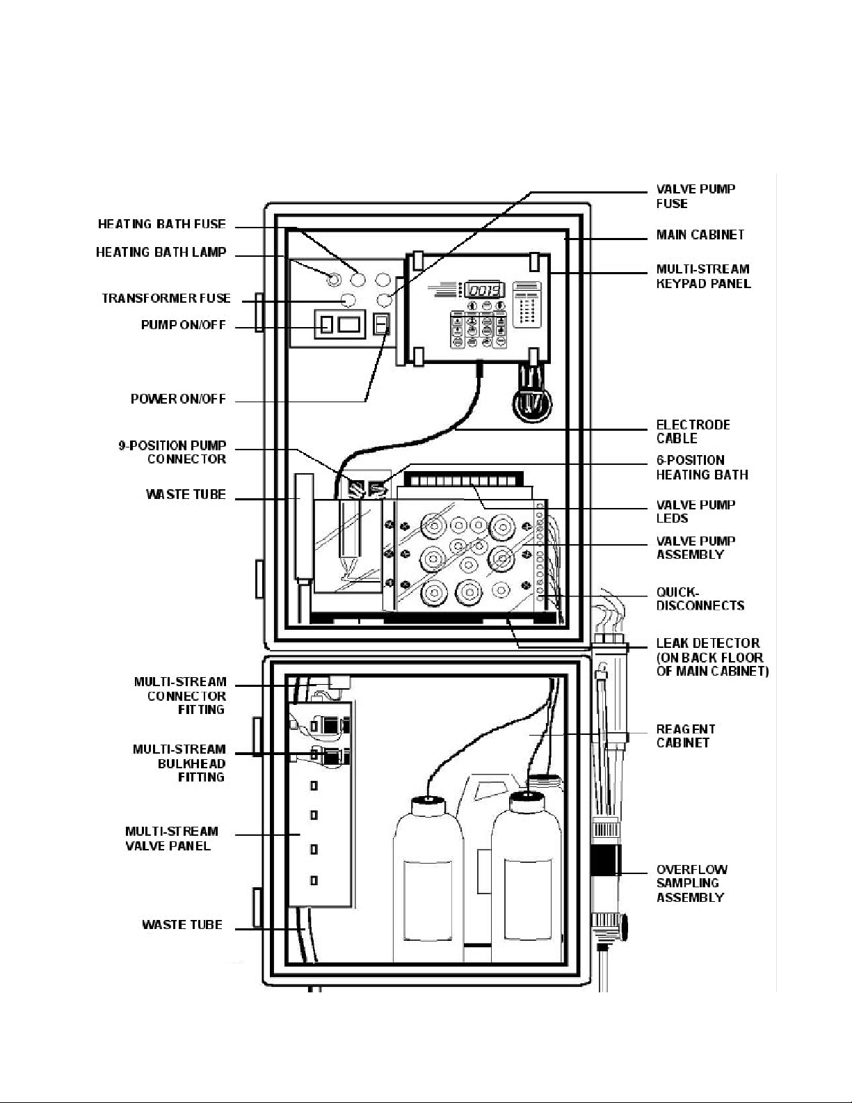
Figure 21 to view a completely installed analyzer.
Figure 21. Opened Assembled Cabinet
Page 12

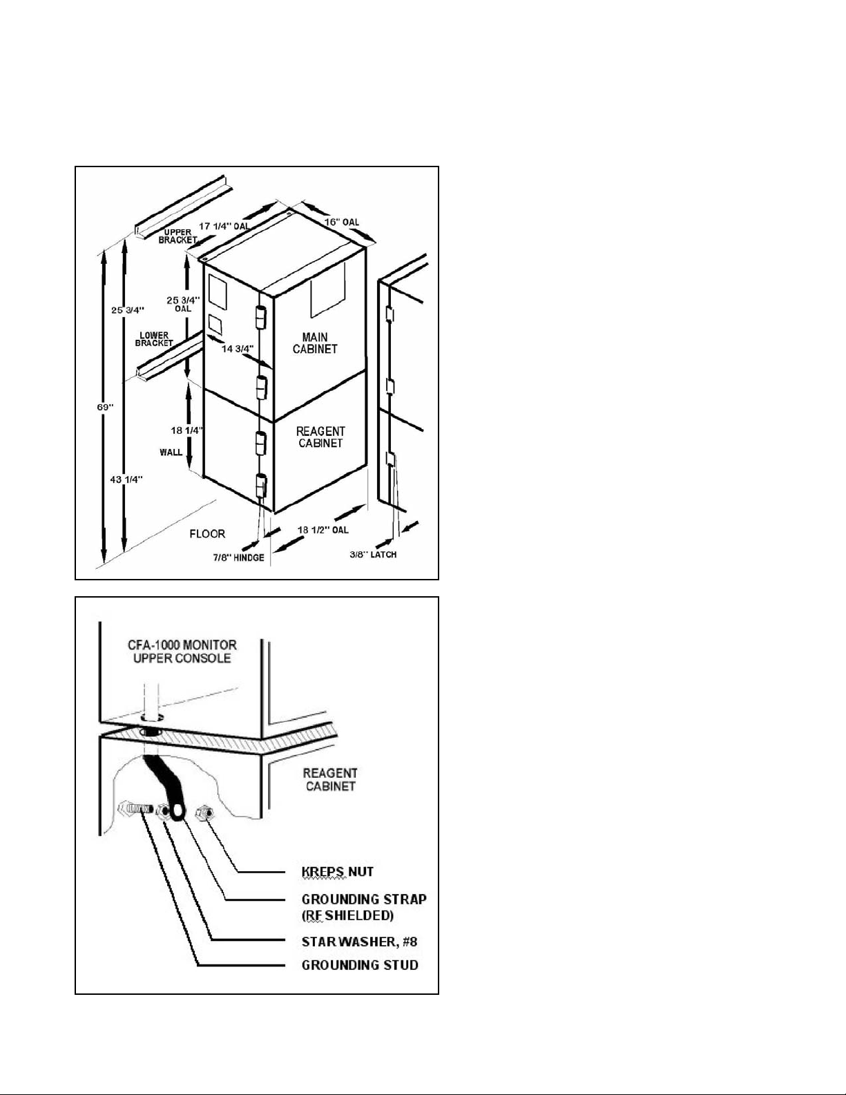
To mount main cabinet, proceed as follows (see Figure 22):
1. Securely attach supplied "L" brackets to wall using suitable hardware. Brackets must be anchored properly
to support 250 pounds (113.6 kg).
2. Attach main cabinet to "L" brackets using supplied four bolts, split ring washers, and hex nuts.
2.3 Mount Reagent Cabinet
To mount reagent cabinet, proceed as follows:
1. Loosen the four bolts in bottom of main cabinet.
2. Lift reagent cabinet and attach to main cabinet by placing heads of bolts into keyhole slots in top of
reagent cabinet.
3. Slide reagent cabinet back.
4. Feed grounding strap on bottom of main cabinet through notched hole in left rear corner and attach it to
stud on back of reagent cabinet (see Figure 23).
5. Tighten screws to attach reagent cabinet to main cabinet.
6. For multistream units, plug valve bank cable into positive fit receptacle at left side of cabinet (refer to
Figure 71, “Multistream Valve Panel Connector”).
6
CFA3000 ISE Analyzer
Instruction Manual
2.2 Mount Main Cabinet
General Recommendations
This cabinet is not for outdoor installation.
Environmental conditions of enclosed facility:
• Temperature:
min. 50°F to max. 113°F
(min 10°C – max. 45°C)
±10° within regulated range.
• Humidity: noncondensing
Mount cabinet on a wall or other suitable vertical surface, at least 42” (107 cm) wide and
431/2” (111 cm) off the floor.
Mounting surface must be able to support 250 pounds (113.6 kg).
Allow 11/2 feet (.5 m) of clearance at left side of analyzer for access to input/output panel,
and allow for swing out for rear access.
Allow 12” (.3 m) at right side for access to overflow tube assembly (if single stream).
Mount cabinet level, or with a slight backward tilt for proper leak detector operation.
Page 13
7
CFA3000 ISE Analyzer
Instruction Manual
Figure 22. Mounting Main and
Reagent Cabinets
Figure 23. Attaching
Grounding Strap
Page 14

8
CFA3000 ISE Analyzer
Instruction Manual
2.4 Install Waste Tube
To install waste tube, proceed as follows (refer to Figure 21):
1. Guide waste tube through main cabinet into reagent cabinet and out through bottom of reagent cabinet.
2. Secure plastic waste tube in clamp in lower right side of main cabinet.
3. Insert Colorimeter drain tube into waste tube.
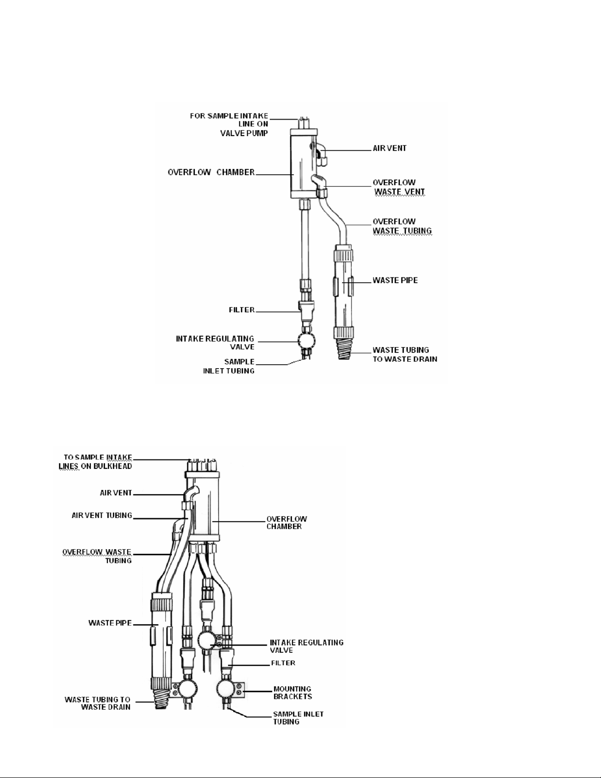
2.5 Mount Overflow Sampling Assembly
To mount overflow sampling assembly proceed as follows (for sample configurations, see Figures 24a and 24b):
1. Mount overflow sampler assembly on outer, right side of reagent cabinet using the provided four machine
screws. For multistream units, mount overflow assembly on left side of cabinet. (If using IF100 InLine
Filter, refer to instruction sheet accompanying filter for complete installation instructions.)
2. Place ends of air vent tubing and overflow waste tubing into waste pipe.
3. Connect waste pipe to drain.
4. Supply sample stream to regulating or intake valve with 1/4” tubing (plastic or steel) as follows: Insert
tubing into tube fitting. Make sure tubing rests firmly on shoulder of fitting and nut is fingertight. Mark
nut at 6 o’clock position. While holding fitting body steady with a wrench, tighten nut 11/4 turns (go to 9
o’clock position).
5. For multistream assembly, connect sample intake line to bulkhead fitting.
6. For singlestream assembly, attach sample intake line to valve pump.
7. Make sure that sample liquid overflows into overflow chamber.
The Sample intake tube should extend into
The overflow tube approximately 1½” – 2”
3.81 –5.08 cm).
Page 15
9
CFA3000 ISE Analyzer
Instruction Manual
Figure 24b. Multi
stream Overflow
Sampling Assembly,
threestream option)
Figure 24a. Singlestream Overflow Sampling Assembly
Page 16

10
CFA3000 ISE Analyzer
Instruction Manual
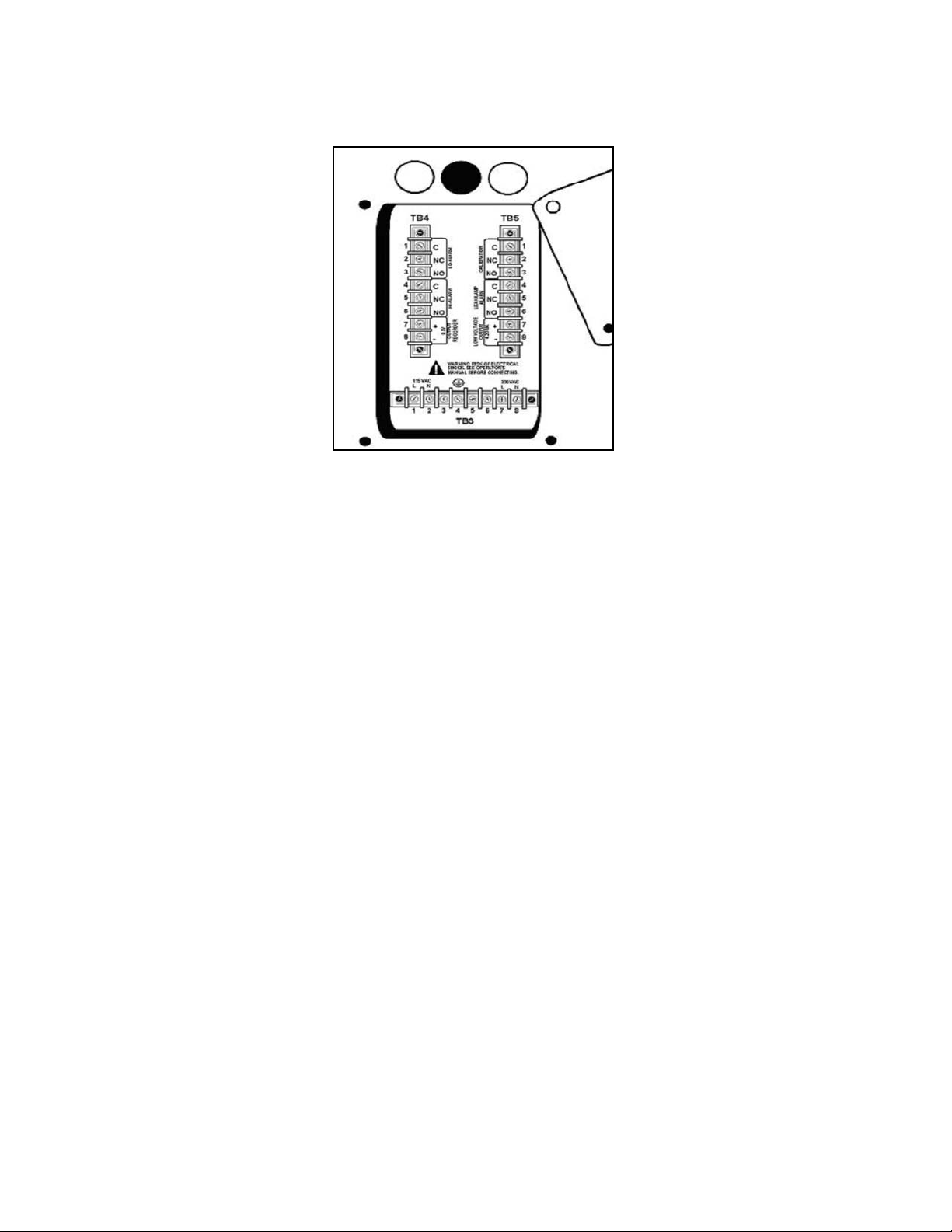
Electrical connections are made to and from the cabinet at the input/output panel, located on the left side of the
analyzer. See Figure 25.
• Terminals are provided for ground, power supply, high/low alarms, output signals, calibration and status
relays
• Output signals a voltage output of 05 Vdc and a floating, ungrounded current output of 420 mA are
available for remote readout or control of a process.
• Also available are contact closures for the following:
High alarm Calibration
Low Alarm Leak Alarm
To make electrical connections, proceed as follows:
1. Remove solid caps from the holes above the input/output panel by puncturing with an awl and prying
them out. (Note: remove caps only from those holes that will be used.)
2. Replace with permanent connectors.
3. Connect alarms and external computer interfaces (if any).
4. Feed 3wire power cable into analyzer through hole above the input/output panel.
5. Connect wires to appropriate contacts on Terminal Strip TB3.(See next page)
2.6 Prepare Electrical Connections
Use cable glands to hold cables securely in holes above input/output panel.
WARNING:
Connect output signals, if any before connecting the power supply.
CAUTION:
For proper operation and for safety, electrical connections to this equipment must be
made in accordance with local or national electrical code as applicable.
This equipment must be grounded. A qualified electrician should wire this equipment to an
electrical circuit.
Page 17
11
CFA3000 ISE Analyzer
Instruction Manual
Figure 25.
Input/Output Panel
2.7 Install Valve Pump Assembly
The pump assembly has a vacuum pressure system that:
l Eliminates internal pump tubing
l Uses significantly less reagent
l Accurately moves fluids through the analyzer.
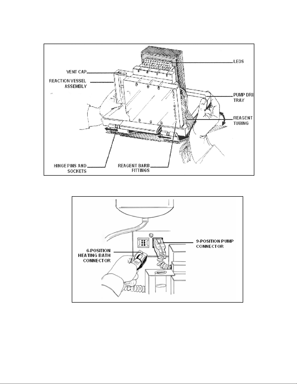
Perform the following procedure to install valve pump assembly:
1. Tilt pump assembly towards you.
2. Align the hinge pins and sockets, and slide assembly tray as far as possible to right (see Figure 27).
Carefully lay tray down into cabinet
3. Plug in the two connectors to the back of the cabinet (6position connector for heating bath; 9position
connector for pump) (see Figure 28).
4. Connect 16pin connector from pump assembly to small connector on CPU board (yellow ejector) above
connector for keypad panel.
5. Attach colorimeter inlet tubing on left side of pump to flowcell inlet (see Figure 21).
6. Continue with procedure depending on whether system is singlestream or multistream.
For singlestream, continue:
6. Thread tube labeled Sample" through hole 0n bottom of shelf to the right of pump assembly, and out
through hole on left side of cabinet.
7. Connect Sample tube to top of overflow sample on left side of cabinet.
8. Guide all other tubes that are attached to valve pump assembly through reagent cabinet access hole.
For multistream, continue:
6. Thread Sample tube from pump assembly through reagent access hole on the right side of the valve
pump assembly, and connect to Common (C) on #1 multistream solenoid valve on left side of reagent
cabinet.
Guide all other tubes that are attached to valve pump assembly through reagent cabinet access hole.
Page 18
12
CFA3000 ISE Analyzer
Instruction Manual
Figure 26. Valve Pump Assembly
Figure 27. Pump Connector
Page 19
13
CFA3000 ISE Analyzer
Instruction Manual
2.8 Prepare Reagent Containers
Prepare reagent containers as follows:
1. Remove screw caps from reagent bottles.
2. Using an awl, make one hole in foil for the reagent straw. Do not allow awl to touch reagent or standards.
3. Place Standard and Reagent bottles into reagent cabinet, as shown in Figure 28.
4. Insert colorcoded reagent straws and labeled Standard straw leading from valve pump assembly into holes
punched in corresponding bottles.
Figure 28. Sample Bottle Placement in Cabinet (for all methods; colors refer to reagent straw colors)
Page 20

14
CFA3000 ISE Analyzer
Instruction Manual
3.0 Operating the Analyzer
3.1 Operational Overview
The analyzer uses a batch flow method for automatically analyzing a sample against a fixed standard (refer to block
diagram in Figure 31). That is, the touch of a button starts the microprocessorcontrolled program, calibrates the
analyzer, takes measurements of samples, and reports results directly unattendedfor months at a time.
The automated monitoring program determines the sequence for activating each of the valve pumps in the valve
pump assembly to inject air and fluids into the reaction chamber. Each valve pump is associated with a specific
input via the quick disconnect connector on the side of the assembly (the number of reagents is determined by
your particular chemistry and procedure).For example, the inputs for sodium chemistry would be:
• Buffer or Ionic Strength Adjustor, reagent #1
• Sample
• Grab sample
• Baseline
• Standard
• Air
• Evacuation of chamber
• Recirculate
For a multistream system, solenoid valves in the analyzer reagent cabinet open and close streams for sampling.
When sampling, the keypad panel LEDs identify which sample stream (valve number) is associated with the dis
played value, and which valve is now open for sampling. Although the system runs samples on its own, you may
also perform a manual grab sampling or a manual calibration at any time.
Figure 31. Simple Block Diagram
Valve
Pump
Electronics
Data output
ISE
(ion selective
electrode)
Reaction
Cell
SECTION 3
OPERATING THE ANALYZER
Page 21

15
CFA3000 ISE Analyzer
Instruction Manual
3.2 Check Sample Stream
• Check that the sample intake tube is 1½ to 2 inch (3.81 to 5.08 cm) into the liquid.
• Sample should just overflow the overflow tube. There should be no particulate or bubbles in the tube.
Using a MultiStream Overflow Sampler
Multistream analysis requires an overflow sampler assembly that will accommodate the extra sample streams.
One multistream chamber allows for up to three sample streams; for 4 6 streams, use two chambers.
The sample tubes connect to solenoid valves in the reagent cabinet. The analyzer uses the valves to cycle
through all sample lines, in sequence. First, stream 1 valve is opened, and Valve 1 LED on the keypad panel is
lit. When the measurement is complete, Valve 1 will be closed, and Valve 2 is opened to begin sampling stream
2. The keypad panel will show Valve 1 LED lit as the Displayed Stream, and Valve 2 LED is lit for the Selected
Stream.
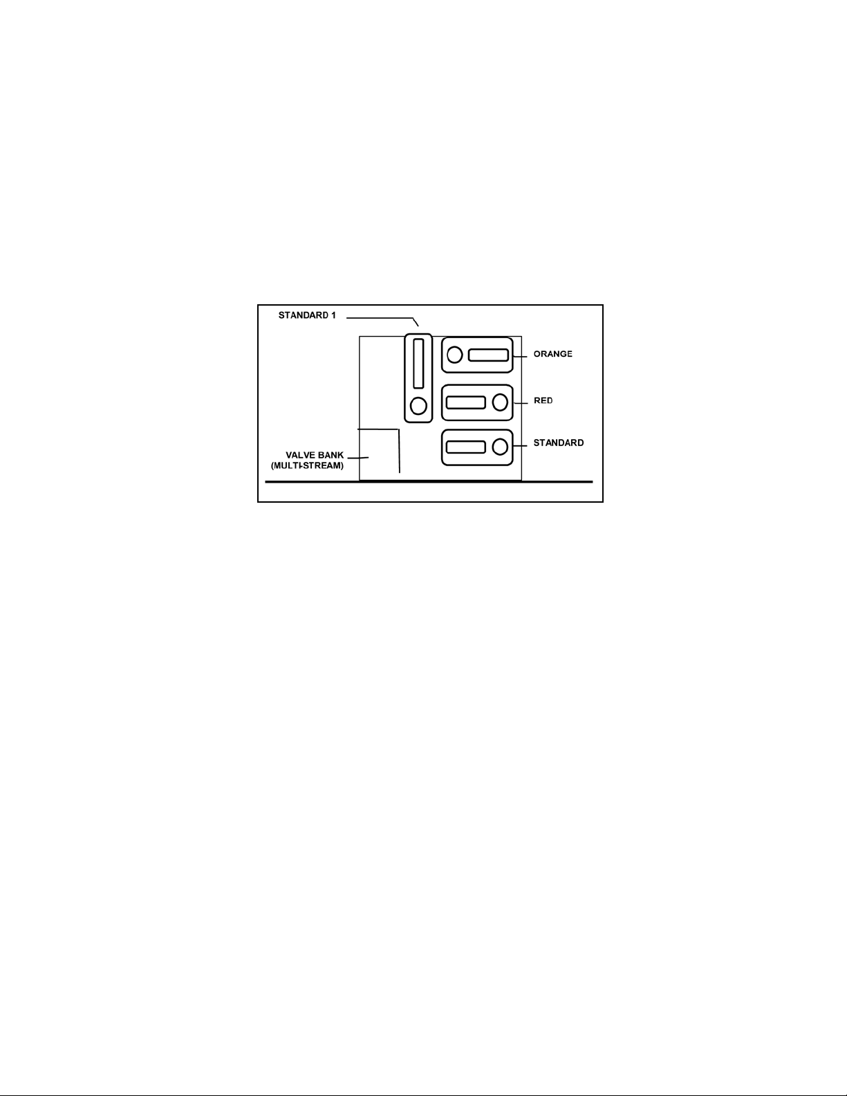
LED's on the valve pump assembly light up when a particular fluid is taken up by the valve pump assembly.
Figure 32 identifies the valve pump LED designations.
3.2.1 Check Fluidics
Check the following:
• Liquid should overflow in overflow chamber.
• Waste tubing is in waste pipe.
• Sample tube is connected to Overflow Sampler Assembly for single stream; and, for multistream, it is
connected to Common (C) port of sample solenoid valve #1, on left side of reagent cabinet.
• System has no leaks.
3.2.2 Check Reagents
Check the following:
• One hole has been punched in all reagent cap liners.
• Reagent straws are placed in appropriate reagent containers.
• High and low standard tubing are in appropriate containers.
3.2.3 Turn On Power
1. Open the keypad panel door to expose the circuit boards.
2. Press each board in to ensure proper seating.
3. Simultaneously press Power button on the back wall of upper cabinet and Reset button on the CPU board
(yellow ejector), then release.
4. First release the Power button, then the Reset button. The Keypad should display ”H E L O", then four
dashes " ".
5. Pull pump forward and check leak detector by dipping finger in tap water and touching detector behind
pump. Leak detector LED on keypad panel will light up.
6. Turn main power switch to OFF.
7. Dry leak detector
8. Wait 20 seconds, then switch main power switch back to ON. Leak detector LED should be off.
Page 22
16
CFA3000 ISE Analyzer
Instruction Manual
3.2.4 Test Valve Pump Operation
Reaction cell takes approx. 30 minutes to heat up.
If leak detector LED does not light up:
Adjust potentiometer on analog board counterclockwise for more sensitivity.
Turn off power to reset system.
Wait 20 seconds, and simultaneously press Power and Reset buttons.
Dip finger in tap water and touch leak detector contacts on bottom of cabinet behind the valve
pump. LED should light up.
If problem persists, contact Rosemount Analytical.
The test procedure allows you to confirm that all physical connections are installed properly,
and to ensure that the pump is taking up the proper fluids at the correct time.
Enter Test Mode:
1. Put all straws and Sampling tube into a beaker of DI water.
2. Turn power on by simultaneously pressing Power button on the back of
upper cabinet and Reset button on CPUboard (yellow ejector).
3. First release Power button, then Reset button. Keypad should display "H E L O",
then four dashes " ".
To enter test mode, continue with the step appropriate for your analyzer setup:
For singlestream,
continue:
For multistream,
continue:
Referring to Figure
32, on keypad
panel, press posi
tion 15 and then 2
On keypad panel,
press: then
.
DECIMAL
MANUAL
Page 23
17
CFA3000 MANUAL SECTION 3
INSTRUMENT DESCRIPTION
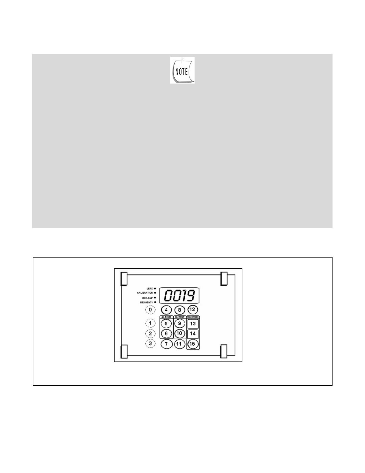
FIGURE 32. KEYPAD PANEL
The keypad buttons may now be used to test pump operation. Do not rush through
the test steps – when a specific step is initiated, it takes approx. 2 seconds to pump air
through the system. Actual pumping of a liquid takes approximately 4 seconds. After this operation
is finished, another 4 seconds elapses before the pump is primed for the next test step.
To exit the test at any time, press the ENTER button on the keypad panel.
If a test step does not work properly, try the following:
√ Take a syringe and shoot air through straw to make sure it is not clogged.
√ Check that corresponding LED on valve pumps lights up (refer to Figure 41).
√ Check that fluid is picked up in correct tube.
If the problem still persists, contact Rosemount Analytical.
Begin Test:
Confirm that the corresponding Pump LED lights up for each step (refer to Figure 33 for LED designations during
test):
Page 24

18
CFA3000 MANUAL SECTION 3
INSTRUMENT DESCRIPTION
2. Press to simulate one shot of Reagent #4. Look at blue straw to confirm that water is pumped up
through tube. Repeat a few times until you see water is in clear section of tube
3. Press to simulate one shot of Reagent #3. Check green straw and its clear tube
4. Press to simulate one shot of Reagent #2. Check orange straw and its clear tube.
5. Press to simulate one shot of Reagent #1. Check red straw and its clear tube
6. Press to simulate one shot of Sample coming from overflow sampler. Check tube labeled "Sample."
7. Confirm that fluid is going to flowcell.
8. Press to simulate one shot of Standard. Check corresponding clear straw and its clear tube.
9. Press to pump one shot of air into analyzer.
10. Press to simulate one shot of Baseline solution. Check clear straw labeled, BASELINE, and tube.
11. Repeat Step 9 until you see fluid shoot into reaction chamber.
12. Press to simulate evacuation from the reaction chamber to the flowcell. Check the tube going up to
flowcell.
13. Press to simulate one shot of Grab solution. Check clear straw and tube.
14. Press to wash flowcell.
1. Press ZERO to test air. Press ZERO to turn off.
Page 25

19
CFA3000 MANUAL SECTION 3
INSTRUMENT DESCRIPTION
15. Press to empty reaction chamber. If there is any fluid left, it will be shot through to Waste.
16. Press once to exit test.
NOTE: The LCD on the display board will display the keypad position which is assigned to a specific
valvepump. When the LCD number disappears, the next position may be pressed. The sequence is
given on page 24.
Figure 33. Valve Pump LED Designations
Page 26

20
CFA3000 MANUAL SECTION 3
INSTRUMENT DESCRIPTION
3.2.5 Set Up Stream Parameters
The analyzer is programmed to measure a singlestream system at 4 sample cycles per hour. The multistream
default is 1 cycle per stream, but you may define parameters for individual streams, such as modifying the num
ber of cycles or the alarm threshold values.
The alarm values are used to activate alarms or controllers when the sample is outside of the specified concen
tration range. A high alarm will activate when the sample concentration exceeds a preset limit. A low alarm will
activate when the sample concentration is below the preset limit.
The contacts for the alarm outputs are located at the input/output panel on the cabinet side. The system must be
in an alarm condition for at least one minute to activate the alarm contact.
Use the logical flows below to define desired stream parameters.
Figure 34. Logic Flow for Singlestream Parameter Definition
Page 27

21
CFA3000 MANUAL SECTION 3
INSTRUMENT DESCRIPTION
Figure 35. Logic Flow for Multistream Parameter Definition
(Note: Use decimal on the keypad using arrows to place decimal in the correct position)
Page 28

22
CFA3000 MANUAL SECTION 3
INSTRUMENT DESCRIPTION
3.3 Set Reagent Supply Time
Use the keypad panel to remind you when you need to replace the reagent. The analyzer will count pump cycles
and count down the number of days left. To specify the duration, proceed as follows:
1. Press once to set counter for 90 days (3 months).
Sample Display: 0 0 9 0
2. Press to exit and clear display.
To determine how many days are left until you have to replace reagent,
Press: once.
Look at the LCD and record the number of days;
then press: again to get out of mode.
3.4 Set Scaling Outputs
Set output 420 mA 05 Vdc from the keypad panel, (refer to Figures 72 and 73), then adjust 420 mA and 05
Vdc at your external device.
Set output scale to: 4 mA/0 V
1. Press: .once then .to display 4 mA and for 0 Vdc.
The sample Display for 4 mA and for 0 Vdc: 0 0 0 4
2. To exit, press
Set output scale to: 20 mA/5 V
1. Press once then to display 20 mA and 5 Vdc.
Page 29

23
CFA3000 MANUAL SECTION 3
INSTRUMENT DESCRIPTION
2. The sample display for 20 mA and for 5 Vdc: 0020
2. To exit, press .
To display the fullscale concentration embedded in the EProm:
Press two times. To exit, press .
3.4.1 Record
mV
Use the mV value to determine that the method’s span and slope are correct. The change in millivolts (mV)
is the spread between a baseline and a fullscale standard at the time of calibration. The values are relative to
the chemical parameter being measured
Record the millivolt values for both baseline and fullscale standard.
1. Press
The sample Display for value of 150 mV is: 0 1 5 0
2. To exit function, press once.
3.4.2 Initiate Auto Calibration
The analyzer is calibrated automatically usually every two days, depending on the chemistry. Auto calibration
performs both baseline and fullscale calibration. Baseline calibration measures a solution with 10% concentra
tion of the species of interest. Fullscale calibration measures a standard solution in the upper range of the
parameter of interest.
Before starting calibration, make sure that the analyzer is running reaqgents and baseline
solution for at least 20 minutes.
Page 30

24
CFA3000 MANUAL SECTION 3
INSTRUMENT DESCRIPTION
To initiate auto calibration, press on the keypad panel – the CALIBRATION LED will light. When multi
stream systems are being calibrated, only Stream 1 LED is lit.
Baseline calibration will run first for approximately 15 minutes. Fullscale calibration follows, lasting approximately
15 minutes (the actual time for calibration depends on the chemistry). When fullscale calibration is finished,
CALIBRATION LED goes out and the value is displayed on the LCD. The “ ” display signifies that a delay
is required before the next sample is displayed.
Sample analysis automatically begins after calibration. The time delay from the start of sample analysis to dis
play of results is approximately 15 minutes. This allows sufficient time for the previous solution to wash through
system, for sample and reagents to react, for analyzer to measure sample and display concentration value.
When the CALIBRATION LED and the ”000” display in a singlestream system go out, the displayed value on
the keypad panel is the actual stream value.
For a multistream system, after auto calibration, Sample Stream status LED’s will light to show sample stream
valve currently selected and sample stream concentration currently displayed. For example, for the first stream
sample, VALVE SELECTED LED is lit for that stream; dashes display on the keypad panel. When analyzer finish
es sampling one stream and moves on to the next, the display shows the previous sample stream concentration
value, and its VALVE DISPLAYED LED lights up. VALVE SELECTED LED will be lit for next valve in sequence.
Note: If for any reason a calibration is not wanted and needs to be aborted, press:
then, , then to abort the calibration. Press twice in rapid succession on initial
startup for priming of sample & reagents
3.5 Process a Grab Sample
The analyzer allows you to rapidly analyze a grab sample.
Press on the keypad panel, to introduce a grab sample into the analyzer from the holder on the overflow
sample panel.
If visible, suspended solids are present in the sample, filter it to 8 microns or less.
Page 31

25
CFA3000 MANUAL SECTION 3
INSTRUMENT DESCRIPTION
Place the clear grab sample inlet tube into a beaker containing the grab sample.
2. Press one time. The display shows flashing dashes, “ “ .
The system analyzes the grab sample and after 15 minutes, displays the results when complete (The results
are “flashed” on the display).
Grab Sample Display: 10.0 (flashing for three minutes)
After the display of the grab sample’s value, a multistream analyzer begins processing the next stream in sequence.
3. To display measurement for previous grab sample, press twice.
4. Press button to return to normal operation.
3.6 Manually Sample a Particular Stream.
Use this procedure to manually switch between sample streams in a multistream system. This operation can be
performed at any time, except during calibration.
Press one time. Sample Display: 0 0 0 1 .
Press and to change stream number. Sample Display: 0 0 0 3
Press to start sampling desired stream.
Press to return to multistream automatic analysis.
3.7 Shutdown
To shut down the CFA3000 for only a few days, press main Power button in back of upper cabinet to OFF
position. Leave reagent straws in reagent containers.
Page 32

26
CFA3000 MANUAL SECTION 3
INSTRUMENT DESCRIPTION
To shut down the analyzer for more than a day, perform the following procedure
1. Remove straws from reagent containers and place them into a beaker of DI water.
2. Press twice within a twosecond interval to activate priming. This allows wash solution or DI
water to be injected rapidly through system.
3. After priming finishes (after 15 minutes or when “auto cal” starts), press the main Power button in back of
upper cabinet to OFF position.
3.8 Quick Start
If the analyzer has been shut down during normal operations, turn power on and
press once.
If the CFA3000 has been turned off for an extended shutdown:
Press twice to prime; the system will automatically go into :”Auto Cal” after priming
Some chemistries may require specific wash solutions. Check Appendix A,
"Chemistries," for details.
Page 33

27
CFA3000 MANUAL SECTION 4
MAINTAINING THE ANALYZER
Your CFA3000 Series analyzer is a precision instrument which, if maintained properly, should provide years of
accurate and reliable service.
4.1 Analyzer Equipment.
Even though the analyzer normally runs automatically, perform the following activities, quarterly:
1. Start Auto Calibration after reagent replenishment (see Section, "Perform Auto Calibration").
2. Check mV value
SECTION 4
MAINTAINING THE ANALYZER
Page 34

28
CFA3000 MANUAL SECTION 5
TROUBLESHOOTING PROCEDURES
This chapter is divided into two sections:
• Troubleshooting Chart: a list of symptoms, probable causes, and remedies.
• Test Functions:– test functions for diagnostic information.
5.1 Troubleshooting Chart
Symptoms observed during operation are generally enough to identify a faulty component.Such symptoms,
together with probable causesand remedies are listed in the following troubleshooting chart.
Problem Probable Cause Remedy
No power
Power switch
OFF
Press power
switch ON
Power switch
failed
Call Rosemount
Analytical
Pump is
inoperative
Valve pump
switch OFF
Press switch ON
Blown fuse Replace fuse
Leak detector
activated
Find and fix
leaking; check
pump’s electrical
connection
Bad electrical
connection
Check pump’s
plugs to CPU &
connector
Still inoperative
Call Rosemount
Analytical
Keypad lights or
display fails to
light up
or buttons fail to
operate
Circuit boards
are not seated
properly
Remove and
reinstall circuit
boards
Display or
associated
power circuit
faulty
Call Rosemount
Analytical
Problem Probable Cause Remedy
Keypad lights or
display fails to
light up
or buttons fail to
operate
Display or
associated
power circuit
faulty
Call Rosemount
Analytical
Connector faulty
or not properly
inserted
Check
connection
SECTION 5
TROUBLESHOOTING PROCEDURES
Table 51: Troubleshooting Chart
Page 35

29
CFA3000 MANUAL SECTION 5
TROUBLESHOOTING PROCEDURES
Problem Probable Cause Remedy
Alarms not
activated
Incorrect
settings
Readjust
settings, making
sure that low
alarm is set
lower than
high alarm
Insufficient time
for alarm to
respond
Alarm condition
must exist for
minimum of 60
seconds before
alarm activates
Signal not
repetitive
(same sample
not repetitive)
Small leak or
clogging in
fluidics
Check all tubing
lines and
connections
Clogged tubing Replace tubing
No signal, or
signal “offscale”
high
Connector or
wires loose
Faulty circuit
board
Incorrect mV
value
Check circuit
boards for
proper seating
Replace power
supply circuit
board
Loss of mV
Sensitivity
LED ISE on
Reagents,
standards old,
contaminated or
improperly
prepared
Change
reagents
Reagent straws
in wrong
reagent or
standard
Check
placement of
straws
Problem Probable Cause Remedy
Loss of sample
flow
Replace sample
filter on overflow
panel
Decreased
pumping volume
Tubes pinched
shut or clogged
from deposits
Remove
condition
causing
“pinched” lines;
replace sample
filter at overflow
panel
Leak detector
LED lights up
Leak in fluidics Repair leak and
dry leak detector
contacts; turn
main power
OFF for
20 seconds
High humidity Adjust screw on
leak detector
potentiometer
on analog
board; turn
clockwise to
decrease
sensitivity
Connector faulty
or not properly
insertede
Check
connection to
analog board;
replace analog
board.
5.2 Test Functions
Table 52: Test Functions
Problem Probable Cause Remedy
Front panel
display
Test LED’s and
LCD on keypad:
a. Press Power
button and reset
button on the
CPU board (yel
low ejector)
b. Release
power, then
Reset button.
Press power
Press:
Page 36

30
CFA3000 MANUAL SECTION 5
TROUBLESHOOTING PROCEDURES
Check
button.
Test Procedure
Exit
Front panel
display
c. Press the
following keys in
sequence: (key
#’s 15, 5, 6)
Press:
Sensitivity
(mV)
Press:
then
Press:
then
Page 37

31
SECTION 6
REPAIR PROCEDURES
CFA3000 MANUAL SECTION 6
REPAIR PROCEDURES
The Ionselective electrode analyzers are designed with modular components for quick and easy replacement.
The following sections contain instructions to remove parts and replace them. For more complex repairs, or diag
nostic assistance, contact Rosemount Analytical at:
• Telephone: (800) 8548257, (949) 7578500
• Fax: (949) 4747250
• Email: www.raihome.com
6.1 Replace Valve Pump Assembly
Use the following procedure to replace pump assembly:
1. Turn off power to analyzer.
2. Pull back of pump assembly towards you to a 45degree angle (see Figure 61).
3. Unplug the two connectors from the back of the cabinet. (9position connector for pump).
4. Disconnect pump assembly’s “D” connector from right side of pump.
5. Remove all liquid tubes from pump.
6. Disconnect waste tube from bottom of reaction cell (right side of valve pump).
7. Slide assembly to the left to disengage from pins, and remove pump assembly.
8. To install a new pump assembly, refer to Section, " Install Valve Pump Assembly".
Figure 61. Remove Valve Pump Assembly
Page 38

32
6.2 Replace Circuit Boards
Use the following procedure to replace circuit boards:
1. Turn off power.
2. Open latch from right side of keypad panel; and open door.
3. Disconnect all cables and plugs from board to be replaced.
4. Unlatch colored clip from board to be replaced (refer to Figure 62).
5. Pull circuit board straight out.
6. Reverse steps to replace board and reconnect cables. Press firmly to ensure that boards are
properly seated.
7. Turn power on.
8. Perform Automatic Calibration (refer to Section, “Initiate Auto Calibration”).
Please NOTE: Valvepump connector is on CPU board
Figure 62. Card Cage
CFA3000 MANUAL SECTION 6
REPAIR PROCEDURES
IMPORTANT: Do Not remove any PC board or component without first shutting off Power to the analyzer.
Page 39

33
6.3 Replace Fuses
Use the following procedure to replace fuses (all fuses are 1A):
1. Turn off power.
2. From inside upper left corner near pump switch, press down on fuse cap and turn counterclock
wise to remove.
3. Pull fuse and cap straight out.
4. Replace fuse in cap (make sure the new fuse is the same type and rating as the one you are
replacing).
5. Press fuse cap in place and turn clockwise.
6. Turn power on.
6.4 ISE Reaction Cell Assembly, Electrodes
Figure 63. ISE Reaction Cell Assembly, Electrodes
CFA3000 MANUAL SECTION 6
REPAIR PROCEDURES
6.4.1 The sodium electrode used in the CFA3011 sodium analyzer is a proprietary “solid state” electrode
which is joined with a reference electrode in a sealed cartridge. The buffered sample stream flows into the
reaction cell—through the ground stud to the sodium electrode, then into the reference electrode, out through
the ground stud and then to waste. The sample concentration is measured in the sodium electrode, compared to
the reference value and the sodium concentration is determined.
Page 40

34
CFA3000 MANUAL SECTION 7
INSTRUMENT DESCRIPTION
SECTION 7
INSTRUMENT DESCRIPTION
Part Function
Main Cabinet Splashproof enclosure
protects analyzer
Reagent Cabinet Splashproof enclosure
protects reagents and
solenoid valves
Door Hinges Pin hinges mount doors
on main and reagent
cabinets
Door Latch Secures cabinet door
Keypad Panel and Driver
Board
External side contains
touch buttons for
controlling analyzer,
digital display, and status
panels. Internal side
contains driver board
HB Lamp Indicates when propor
tional controller is heating
the heat bath
HB T 1 A 1 A fuse for heating bath
LAMP PS T 1.0 A 1 A fuse for power supply
to ise lamp
PUMP T 1.0 A 1 A fuse for pump
XFMR T 1.0 A 1 A fuse for transformer
Pump On/Off Lighted switch controls
power to pump
On/Off Main power switch
Colorimeter Detector
Waste Drain Pan Drain pan directs waste
solutions to waste tube
Pump Connector 9position connector
connects pump to main
cabinet electronics
Heating Bath Connector 6position connector
connects to heating bath
assembly
Valve Pump Assembly Includes pump, PC
board, labeled tubes, and
reaction vessel assembly
(chemistry module with
integrated
Part Function
Chemistry Module Tubing Carries sample and
reagent to valve pump
assembly
Quickdisconnects Connects reagents,
samples, and standards
to valve pump assembly
Waste Tube Carries waste solutions
to drain
Leak Detector Senses leakage of
solutions in main cabinet,
shuts pump off, and
activates leak LED
Part Function
MultiStream Valve Panel
(MultiStream option
only)
Allows sequential
analysis of up to six
sample streams
MultiStream Connector
(MultiStream option
only)
Positive fit connector
connects Multistream
valve panel to main cabi
net electronics
Bulkhead Fitting Fitting that directs
individual sample stream
to sample valve
Overflow Sample
Assembly
Supplies continuous
sample streams for
analyzer
7.1 Analyzer Front View (Refer to Fig. 71).
Table 71.1: Main Cabinet Parts
7.1.1 Main Cabinet
7.1.2 Reagent Cabinet
Table 72. Reagent Cabinet Parts
(heating bath)
Page 41

35
Note: For multistream monitor, Overflow Sampling assembly mounts on left side, facing the analyzer
Figure 71. Analyzer Front View
CFA3000 MANUAL SECTION 7
INSTRUMENT DESCRIPTION
Page 42

36
CFA3000 MANUAL SECTION 7
INSTRUMENT DESCRIPTION
Button/LED Function
For Both Single and Multistream Options
LEAK LED When lit, indicates leak in
main cabinet
CALIBRATION LED When lit, indicates
calibration in progress
ISE/LAMP LED Will light when millivolt
level is below default
levels.e
REAGENTS LED When lit, indicates
reagents need to be
replaced
UP or DOWN
Arrow
Increases or decreases
displayed value
Sets value or exits
function
Sets high alarm limit
Sets low alarm limit
Two functions:
Sets 90 day clock for
reagent usage
Displays number of
days remaining until next
replacement of reagents
Sets scale to adjust out
put to 4 mA and 0 Vdc
on recording device
Sets scale to adjust out
put to 20 mA and 5 Vdc
on recording device
Button/LED Function
Function:
Displays Systems mV
Initiates processing from
grab sample
Initiates automatic
calibration of analyzer
Used for setting alarm
values.
For Multistream option only
Sample Streams
LED’s
VALVE SELECTED
shows which valve
(stream) is being
analyzed, and VALVE
DISPLAYED shows
which valve is associated
with completed and
displayed value
Initiates automatic
multistream analysis
Initiates single stream
analysis
Enters function to identify
parameters for each
stream (such as number
of cycles and high and
low alarms)
(Not used)
7.2 Keypad Panel
The keypad panel has a fourdigit liquid crystal display with an adjustable decimal point. The panel also has indi
cator LED’s and pressuresensitive buttons.
Table 73 Buttons/LED Functions
Page 43

37
CFA3000 MANUAL SECTION 7
INSTRUMENT DESCRIPTION
Part Function
Keypad Panel Door Opens to access card
cage
Display Board Circuit board contains
electronics for keypad
and LCD display
CPU Board
180B02801
Central processing circuit
board processes the
signal fed to the digital
display and any external
devices. (Yellow ejector)
Valve Board
180B01601
(only supplied for
multistream option or for
RS232 output on single
stream)
Circuit board controls
multistream accessory.
Jumper should be
installed on back of valve
board. (Purple ejector)
Analog Board
180B02502
For multistream
configurations:
180B02501*
Circuit board converts
signals from analog to
digital and processes
signals from "fault" detec
tors (Orange ejector)
Power Supply Board
180B01203
Supplies voltage to
electrical circuitry
(Blue ejector)
7.3 Card Cage
The card cage is located directly behind the keypad
panel. To access the card cage, lift latches from right
side of keypad panel and open hinged door. (Refer to
Figure 72.)
7.3.1 Card Cage and Door
Table 74: Card Cage Parts
Component Function
0Vdc 5Vdc Connector To recording device.
4mA –20mA Connector To recording device.
Computer Memory Reset Clears microprocessor
memory
Computer Memory Reset Clears microprocessor
memory
Valve Pump Connector Connector for cable from
valve pump
Display Board Cable
Connector
Connector for display
board cable
Component Function
Potentiometer Adjusts sensitivity of leak
detector – clockwise for
less sensitivity;
counterclockwise for
greater sensitivity
Analog Board DIP Switch Contains 8 rocker switches
for setting various
functional processes
(see Figure 73)
Signal Input Connector For process signals
On 180B02501: 20
multistream output
potentiometers
For each stream 2 – 6,
potentiometers for 4 mA,
20 mA, 0 V, 5 V
(multistream only)
Component Function
Multistream Panel
Connector
Connector for cable
connector from display
board
7.3.2 CPU Board
Table 75: CPU Board Components
7.3.3 Analog Board
Table 76: Analog Board Components
7.3.4 Valve Board
Table 77: Valve Board Components
Part Function
18pin Female Connector For relays
6pin Male Connector Operating power
6pin Female Connector Valve Pump Power
7.3.5 Power Supply Board
Table 78 Power Supply Board
Page 44

38
CFA3000 MANUAL SECTION 7
INSTRUMENT DESCRIPTION
PLEASE NOTE: VALVEPUMP CONNECTOR IS ON CPU BOARD
FIGURE 72. CARD CAGE AND BOARDS
IMPORTANT: DO NOT remove any PC board or component without first shutting off Power to the analyzer.
Page 45

39
Figure 73. Analog Board DIP Switches
(with #3 set in OFF position for multistream analyzer) Colorimeter Assembly
CFA3000 MANUAL SECTION 7
INSTRUMENT DESCRIPTION
7.3.6. Analog Board DIP Switches
The following list describes the conditions for each switch to be in the ON or OFF position:
Table 79. Analog Board DIP Switch Positions
Switch No. Position Condition Remarks
1 ON
When using Analog Board, Part
# 180B02602
Analog Board has no adjustment
ports for individual output device
and/or 05 Vdc, 420 mA outputs.
1 OFF
When using Analog Board, Part
# 180B02601
Analog Board has individual ports
for adjusting each output device
(up to 6) and/or 05 Vdc,
420 mA outputs.
2 ON Quick calibration on
2 OFF Quick calibration off
3 ON
4 ON Nonfunctioning switch
5 ON Nonfunctioning switch
6 ON Nonfunctioning switch
7 ON
For stream ID and “brackets” before
and after calibration
Allows markers to be recorded on
strip charts and other recording
devices.
7 OFF
No markers will be recorded on
strip charts and other recording
devices.
8 ON For 80 column printers Formats printer output
8 OFF For 40 column printers Formats printer output
Page 46

40
CFA3000 MANUAL SECTION 7
INSTRUMENT DESCRIPTION
Component Function
Backplane Board Circuit boards plug into
front side
Power Transformer Supplies ac voltage to
electronics
Heating Bath Connector Interconnect to heating
bath
Pump Connector Interconnect to valve
pump
220Vdc Transformer Optional part for specific
electrical requirements
(208 V – 240 V)
Table 710: Back Cabinet Parts
FIGURE 74. REAR OF MAIN CABINET
7.4 Rear of Main Cabinet
In the rear of the main cabinet are a number of
electrical components and connectors. The following
diagram is for reference, only.
Page 47

41
CFA3000 MANUAL SECTION 7
INSTRUMENT DESCRIPTION
Part Function
Pump Housing Contains and protects
valve pump electronics
Pump Valve pump routes
sample and reagents
through the analyzer
Reagent Barb Fittings Male half of tubing
connector. Tubes are
connected to reagents
and sample
Reaction Vessel
Assembly
Contains reaction cell,
heating block
6position Connector Electrical power to
heating bath
9position Connector Electrical power to pump
LED Green is OK; RED is
Low pressure
Part Function
Sample and Reagent
Tubing
Colorcoded straws and
labeled tubes for
transport of solutions
“D” Connector Connects to small, 16pin
connector on CPU boards
Vent Line Vents reaction cell to
waste
Pump Drip Tray Catches leaks and
directs them to the leak
detector
LEDS Identify which injector is
active.
7.5 Valve Pump Assembly
The vacuum pump assembly includes the pump, PC
board, and reaction cell.
Table 7 11: Valve Pump Parts
* Vacuum/Pressure LED is located on the upper right
corner of the ValvePump as it is installed
Figure 75. Valve Pump Assembly
Page 48

42
CFA3000 MANUAL SECTION 7
INSTRUMENT DESCRIPTION
Port Function
RS232C For connection of
computer interface or
other accessories
Relay Output Optional relay contact
(multistream analyzer
only)
Printer For connection of printer
cable
Recorder For connection of
external recorder; for
multioutput, 420 mA
and 05 Vdc outputs for
streams 2 through 6.
Pin No. Description
1 NO 9 C Stream #1 Alarm or ID
2 NO 10 C Stream #2 Alarm or ID
3 NO 11 C Stream #3 Alarm or ID
4 NO 12 C Stream #4 Alarm or (#1*) ID
5 NO 13 C Stream #5 Alarm or (#2*) ID
6 NO 14 C Stream #6 Alarm or (#3*) ID
7.6 Interface Ports
The interface ports (labeled for recorder, printer,
relay output, and RS232) are located on the lower,
left outside wall.
Table 712: Interface Ports
If there are 3 streams or less, both stream ID and
alarms may be optionally configured.
7.8 MultiOutput Board
The output for Stream #1 is obtained from the
Input/Output Panel (see Figure 25). The additional
five outputs are obtained from the lower lefthand side
of the analyzer. Table 714 gives the pin assignments
on the “D” connector for a multistream system:
Figure 76. Interface Ports
7.7 Relay Output Option
This port (see Figure 77) is a collection of contact
closures that can be used to identify either the
stream being displayed or the alarm that is activated
(multistream systems only). these are not “powered”
contacts.
Relay Contact Ratings:
100 Vdc max voltage
10 Vdc max DC current
1.0 A max carry current
0.5 A max switched current
Table 713: Relay Output Option
Pin Assignments
\ 1 2 3 4 5 6 7 8 9 10 11 12 13 14 /
\
15 16 17 18 19 20 21 22 23 24 25 /
Figure 77. "D" Connector for Relay Output
Table 714: Multioutput Pin Assignments on
“D” Connector
2 15 2 14 1
3 17 4 16 3
4 19 6 18 5
5 21 8 20 7
6 23 10 22 9
Page 49

43
CFA3000 MANUAL SECTION 7
INSTRUMENT DESCRIPTION
Part Function
Intake/Regulating Valve Regulates flow of
sample into overflow
sampler assembly
Overflow Tube Assures adequate supply
of sample and
reproducible results by
eliminating positive
pressure from sample
stream.
Sample Intake Tubing Tubing which carries
sample from overflow
tube to analyzer (one to
six stream configurations)
NOTE: Sample intake
tube should be no more
than 1 to 11/2" into the
sample.
Air Vent Allows air to escape
overflow tube as it fills
with sample.
Part Function
Overflow Waste Vent Allows excess sample
to escape.
Waste Pipe Carries waste to drain.
Overflow Tubing All overflow tubes feed
into common waste pipe.
Filters
(180134108)
Replaceable filters are
mounted down stream
from each intake
regulating valve.
Sample Inlet Tubing 1/8" x 1/4" tubing
(provided by customer).
Common Panel Mounts multistream
Overflow Sampler
Assembly to left side of
analyzer (facing front
panel).
Panel with dimensions
221/4” x 9" will support
up to six streams.
7.9: Overflow Sampling
Assemblies
Table 715: Overflow Sampling Assembly Parts
Figure 78. SingleStream Overflow Sampling Assembly
Page 50

44
Figure 79. Multistream Overflow Sampling Assembly
(threestream option)
CFA3000 MANUAL SECTION 7
INSTRUMENT DESCRIPTION
Page 51

45
CFA3000 MANUAL SECTION 8
ADDIDIONAL FEATURES
SECTION 8
ADDITIONAL FEATURES
8.1 Chart Recorders and Data Loggers
A chart recorder or other data acquisition device may be connected to the analyzer for a permanent record of sam
ple concentration. Setting the output 420 mA 05 Vdc from the keypad panel allows you to adjust 420 mA and 0
5 Vdc to a recording device.
These input devices must be isolated or have a floating ground (not reference to ground). The contacts for recorder
output are located at the input/output panel on the side of the analyzer (see Figure 81).
The analyzer will operate normally with data output to the chart recorder or other device. During normal operation,
calibration is performed biweekly. This may vary by Chemistry. To indicate the beginning and end of a calibration
sequence, the recorder makes a quick trace down to zero, and up to full scale. This is called a calibration marker.
After calibration, the recorder resumes recording the sample values (refer to Figure 82).
When a recorder is connected to a multistream system, a ”stream identification blip” (SIB) is produced prior to the
output signal for that particular stream. This allows quick identification of individual stream readings on the
recorder. SIB values are shown in Table 81, and tracings are illustrated in Figure 83.
Figure 81. Input/Output Panel
Table 81: Stream Identification Blips
(SIB’s)
Stream #
Voltage
Output
% Scale of
Recording
Marking
1 0.5 10
2 1.0 20
3 1.5 30
4 2.0 40
5 2.5 50
6 3.0 60
Grab 3.5 70
Page 52

46
CFA3000 MANUAL SECTION 8
ADDIDIONAL FEATURES
Figure 82. Typical Trace Recording with
Calibration of Single Stream System
Page 53
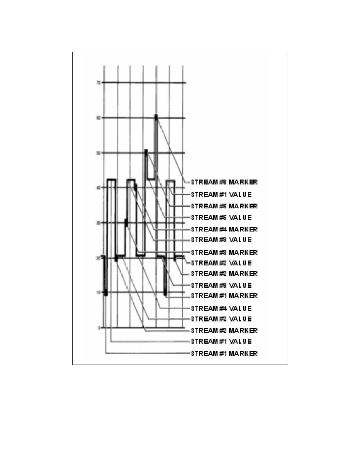
47
CFA3000 MANUAL SECTION 8
ADDIDIONAL FEATURES
Figure 83. Typical Stream Trace Recording with
Calibration of Multistream System
Page 54

8.2.2 Data Configuration
The computer must be set to match the fixed data
configuration of the analyzer, which is:
8.2.3 RS232C Function Commands
The RS232C interface can be used as follows:
• By direct hookup to a nonMacIntosh® based
computer A program on disc can be obtained from
Rosemount Analytical for remote control. Cable
length must less than 150 feet.
• By direct hookup to a nonintelligent terminal. No
program disc is required. Cable length must be less
than 150 feet.
• By communication through a modem. One modem
located at the analyzer can communicate over a
telephone network to another modem hooked up to
an IBM PC or compatible computer or a nonintelli
gent terminal.
Pin configuration is described in Table 84.
Table 84: RS232C Pin Configuration
8.2 Computer Interface
The computer interface is an RS232C serial data
interchange port operating at 1200 baud. The serial port
receives the same information as the printer, and has the
capability to transmit information, enabling remote
control of the analyzer.
8.2.1 Data Output Format
The data output formats contain no control characters,
with the exception of <CR> carriage return, <LF> line
feed, and the preamble/post amble described below:
Table 82: Normal Data Output Format
48
CFA3000 MANUAL SECTION 8
ADDIDIONAL FEATURES
Data Format
Preamble NUL, STX, NUL =
(00, 02, 00 Hex notation)
Date/Time ASCII string of 25
characters, followed by
7 spaces
Concentration ASCII string of 5
characters, followed by
9 spaces
Stream Number One ASCII character
Mode An ASCII string,
consisting of 7 spaces,
followed by three
possible messages:
NOT calibrated, Manual,
or Automatic.
Calibration Status There are two ASCII
messages transmitted:
CAL when calibration is
in progress, and blank
when good data is
available.
Postamble: NUL, EOT,
NUL = (00, 04, 00
Hex notation)
Postamble NUL, EOT, NUL =
(00,04,00 Hex notation)
Pin No.
Circuit
EIA
Circuit
CCITT
Direction of
Signal
Description
1 AA 101
Protective
Ground
*2 BA 103
From
Terminal
Transmitted
Data
*3 BB 104 To Terminal
Received
Data
*4 CA 105
From
Terminal
Request to
Send
*5 CB 106 To Terminal Clear to Send
Parameter. Setting
Baud Rate 1200
Data
8 bits, high order bit set to
zero
Parity None
Stop Bits 1
Page 55

49
CFA3000 MANUAL SECTION 8
ADDIDIONAL FEATURES
*6 CC 107 To Terminal
Data Set
Ready
*7 AB 102
Signal to
Ground
*8 CF 109 To Terminal
Received
Line Signal
Detector
9
Reserved for
Data Set
Testing
10
Reserved for
Data Set
Testing
Rate Selector
24
DA
Transmit
Signal
Element
Timing
25 Unassigned
Pin No.
Circuit
EIA
Circuit
CCITT
Direction of
Signal
Description
11 Unassigned
*12
SCF (High
Speed Indicator)
Secondary
Received
Line Signal
Detector
13 SCB
Secondary
Clear to
Send
14 SBA
Secondary
Transmitted
Data
15 DB
Transmission
Signal Timing
Source
16 SBB
Secondary
Received
Data
17 DD
Receiver
Element
Timing (DCE
Source)
18 Unassigned
19 SCA
Secondary
Request to
Send
*20 CD 108.2
From
Terminal
Data
Terminal
Ready
21 CG
Signal
Quality
Detector
*22 CE
Ring
Indicator
23 CH/CI Data Signal
8.2.4 Initiating RS232Communications to the
Computer
1. With the computer and CFA3000 power turned
off, connect RS232C cable to the computer and
to the RS232C port on the CFA3000 analyzer. (If
a printer is to be used, connect it to the printer port
on the analyzer).
2. Turn on power to the analyzer.
3. From the analyzer keypad panel, turn on the printer
by pressing the following buttons:
• From a multistream keypad:
and , then .
• From a singlestream keypad, referring to Figure
84, press position 5, then 1, and then 10.
4. Turn on computer
Figure 84. Numbered Positions on a
SingleStream Keypad
Page 56

50
5. If you purchased program from Rosemount
Analytical, run it from your computer, by typing in
CFATERM, then press Return.
6. When a blinking cursor appears on the screen,
press Return. The screen will display M>.
7. At this point, all of the RS232C functions listed in
Table 84 are accessible.
8. To set up a file to collect data in the computer,
press <altL> (formatted) or <altC> (capture).
9. Type in file name (up to 8 characters).
10. To start collecting data, press Return. The display
will show a blinking cursor.
11. To access the command functions again, press
Return. The screen will display M>.
Use the commands in Table 85 to control the analyzer.
Table 85: RS232C Commands
CFA3000 MANUAL SECTION 8
ADDIDIONAL FEATURES
Command Function
AUTOCAL Runs fullscale
automatic calibration
AUTOVALV Resumes automatic valve
selection
DATA Forces printing of
analyzer data
DISVALV
Command
Displays stream
parameters, including
sample cycles, low and
Function
MANVALV To operate valves
manually (for multi
stream, one stream
continuously). For
example, to monitor
stream 3, enter
MANVALV 3.
RESET Resets the computer for
a full wipeout
SETCLO Sets clock calendar, Date
is entered as follows: day
of week, year, month,
date, hour, minute,
second. Day of week is
coded as
Sunday = 0, Monday = 1,
Tuesday = 2, etc. Year is
entered as last two digits
of year. Month and date
must be two digits, use
leading zeros as
necessary. A 24 hour
format is used for hour
entry. For example, to set
the clock at Thursday,
April 12, 2003 at 4:35
p.m., enter SETCLO
4030412163500.
SETHAL Changes stream high
alarm setting. For
example, to change
stream 1 to 25, enter
SETHAL 1,25.
SETLAL Changes stream low
alarm
setting. For example, to
change stream 2 to 50,
enter SETLAL 2,50.
SETVTIM Changes stream valve
cycles. For example, to
change stream 2 to 2
cycles, enter
SETVTIM 2,20.
Page 57

Press…
Analyzer
Displays
Press…
5 ENTER
03 ENTER
08 ENTER
16 ENTER
16 ENTER
35 ENTER
51
8.2.5 Printer Interface
The printer interface is a female parallel port designed
to be compatible with IBM PCtype cables and printers.
This builtin capability permits text printing only, no
graphics.
Table 86: Printer Port Pin Configuration
8.2.6 Set Printer Internal Clock
Set printer's internal clock before printing; perform the
following procedure:
1. From analyzer keypad panel, turn on printer:
• From a multistream keypad, press:
and , then .
• From a singlestream keypad, referring to Figure
84, press position 15, then 1, and then 10
2. Enter data as follows:
a. Day of the week first, one digit:
Sunday = 0, Monday =1
Press enter.
b. Year, two digits: 2003 = 03, 2007= 07
Press enter.
c. Month, two digits: Jan = 01,
Feb = 02
Press enter.
d. Day of the month, two digits: 01, 02
Press enter.
e. Hour, using 24hour format:
8:00 AM = 08, 1:00 PM = 13
Press enter.
f. Minute, two digits: 01, 02
Press enter.
Example: To set the clock for Friday, August 16, 2003
at 4:35 PM:
CFA3000 MANUAL SECTION 8
ADDIDIONAL FEATURES
Pin No. Signal Name Description
1 STB/ Negative going pulse
2 D0 Data Bit 0
3 D1 Data Bit 1
4 D2 Data Bit 2
5 D3 Data Bit 3
6 D4 Data Bit 4
7 D5 Data Bit 5
8 D6 Data Bit 6
9 D7 Data Bit 7
10 ACK/ Acknowledge from printer
11 BUSY Busy, from printer
12 PE Paper empty, from printer
13 SEL/
Printer selected, from
printer
14 PFD/ Paper feed, to printer
15 ERR/ Error, from printer
16 INIT/ Initialize, to printer
17 SEL Select, to printer
18 GND Ground
19 GND Ground
20 GND Ground
21 GND Ground
22 GND Ground
23 GND Ground
24 GND Ground
25 GND Ground
Page 58

52
CFA3000 MANUAL APPENDIX
Method: Sodium01A
(0.110, 1100, 101000 ppb to 1000 ppm (contact
Rosemount Analytical for other ranges)
General Description:
For this procedure for the determination of sodium,
the sodium ion is measured potentiometrically using
ion selective electrodes . The addition of an ionic
strength adjustor to the sample maintains constant
background ionic strength and pH.
Sodium in Water
Range: 0.110, 1100, 101000 ppb up to 1000 ppm
or higher.
Reagents Kit: (reagent & standards)
185301130
REAGENT #1, Buffering Reagent:
185301134
Working Standards
10 ppb: 185301133
100 ppb: 182301132
Operating Notes
1. The chemicals used for reagents and distilled water
should be free of sodium.
2. The sample stream must be filtered to 10 microns
or less before being introduced to the system with
an inline filter such as Rosemount Analytical' IF
100
(Part #180140001).
APPENDIX A CHEMISTRIES
Page 59

53
CFA3000 MANUAL APPENDIX
APPENDIX B SPECIFICATIONS
Accuracy: All twodecade ranges up to 1000 ppb
maximum: ±10% of reading or ±2 ppb, whichever is
greater
0.110 ppm range = ±10% of reading or ±0.5 ppm,
whichever is greater
Automatic Calibration: 40 minutes
Total Calibration: 40 minutes, twice/week
Reagent Consumption: 5 L of each reagent per 3
months
Standard Consumption: 1 L of high standard,1 L of
low standard per 3 months
Sample Requirements:
Flow: 4050 mL/min
Current standard bottles are:
“0”(baseline): 1.0 L.
Fullscale: 5.0 L
Pressure: <10 psig (<170 kPa) (overflow cup must
drain to atmosphere)
Temperature: 050° C (32122° F)
Filter: 8 micron filter in sample line is
Recommended; (#180134108).
Multiple Stream Option: General: up to 6 sample
streams; measurement is sequential
Response Time: 15 minutes (methoddependent)
Outputs: 420 mA or 05 Vdc (nonisolated).
(Isolated output is optional.)
Load requirements for 420 mA output: 450 ohms
minimum, 1200 ohms? maximum
Load requirements for 05 Vdc output: 10 k Ohms,
minimum
The range of outputs is the same as the measure
ment range. Parallel output for printer is optional for
single stream, standard for multistream monitors.
RS232C output is optional for single stream monitors,
standard for multistream monitors.
Alarms:
General: contact closures for
• leak detection,
• calibration in progress,
Contact closures are rated:2 A at 250 Vac or 3 A
at 30 Vdc; delay on/off is 1 minute
Streams 2 through 6 (multistream option):
• One alarm relay for each stream; contacts have
dc ratings
• 100 Vdc (maximum carry only)
• 0.5 A (maximum switched)
• delay on/off time is 1 minute
Display: Single line LCD, 4 1/2 digits, readout in
concentration units. For multistream option display
remains at last value until new stream reading is stable.
Status LEDs:
• Leak,
• Lamp failure,
• Quarterly maintenance due
• Calibration in progress.
For multistream analyzers.
StatusLEDs show:
• the sample stream currently selected
• the sample stream for which data is being
displayed.
Environmental: The analyzer is not intended for out
door use. Install in a clean, indoor environment.
Ambient Temperature:
40120° F (1045° C) must be regulated to ± 10°
within range, avoid temperature swings
greater than ± 10° F (± 5± C) over a 12hour period
Humidity: 595% (noncondensing)
Pollution degree: Standard
Altitude: Not applicable
Page 60

54
Dimensions: Height of Analyzer Cabinet:
25.75 in. (654 mm)
Height of Reagent Cabinet: 18.25 in. (464 mm)
Width: 18 in. (457 mm)
Depth: 16 in. (406 mm)
Space Requirements: Wall mounting: Allow 18 in.
(457 mm) on one side for swing out access to rear
panel. Allow 12 in. (305 mm) on the other side for
access to input/output panel and overflow sampler.
Panel Mounting: Allow 12 in. (305 mm) on both sides
for access to input/output panel and overflow panel.
Weight: 117 lb (53 kg).
Add up to 60 lb (27.3 kg) for full weight of
reagents and standards.
Shipping Weight of Analyzer: 138 lb (63 kg)
Shipping Weight of Reagents: up to 64 lb
(29 kg) per kit (3 months supply)
APPENDIX B SPECIFICATIONS Cont.
CFA3000 MANUAL APPENDIX
Page 61

55
The block diagram in Figure C1 graphically shows
the distribution of power and signals throughout the
analyzer. The raised numbers (e.g., (6) ) in the
description below relate to the circled numbers on the
diagram. For clarity, minor components such as fuses
are not shown.
1. For 110 Vac 50/60 Hz option, line power enters
the analyzer at the Power Entry barrier strip TB3 (1),
with the following connections (refer to Figure 25
and Figure C1):
• Line (hot) connection is TB31
• Neutral is TB32
• Safety (chassis) ground connection is TB34
For 220 Vac 50/60 Hz option, the following con
nections are used:
• L1 connection is TB37
• L2 connection is TB38
• Safety (chassis) ground connection is TB34
2. For 110 VAC 50/60 Hz option, line power flows
through the Power Switch and other minor compo
nents to barrier strip TB1. TB1 serves as the line
power distribution point.
For 220 VAC 50/60 Hz option, line power flows
through the Power Switch and other minor compo
nents to the primary of the stepdown Transformer (2).
The Stepdown transformer converts the input 220
VAC to 110 VAC for compatibility with the standard
CFA3000 electronics. From the Stepdown
Transformer secondary power flows to barrier strip
TB1.
3. From TB1, for both options, line power flows to
the Colorimeter Lamp Power Supply, (4) , the Power
Transformer (3) , the Pump Power Supply (5) and the
Power Supply Board (8e) located in the Card Cage (8).
4. The Colorimeter Lamp Power Supply produces
highly regulated DC current which energizes the
Colorimeter Lamp (4a).
5. The Power Transformer converts standard line
voltage to lowvoltage AC for use by the CFA3000
electronics. The Power Transformer secondaries feed
the Power Supply Board, which converts the lowvolt
age AC to regulated DC current, and to the heater
element in the Heating Bath (7) . Relay contacts on
the Power Supply Board are externally available at
the I/O Panel (10) for activation of alarm and status
indicators.
Multistream Analyzer Option
In units equipped with the Multistream option, a
Valve Board (8c) will be installed. This board contains
relay contacts that are externally available at the
Interface Ports (11) as well as LED drivers to activate
the sample stream indicators located on the Keypad
Panel (9) . The Valve Board also provides interfaces
for a printer and serial data communications, exter
nally available at the Interface Ports.
If the monitor includes a multioutput analog board,
analog recorder drivers for each stream are installed
on the Analog Board (8d) . These outputs are exter
nally available at the Interface Ports.
APPENDIX C POWER INTERCONNECT DESCRIPTION
CFA3000 MANUAL APPENDIX
Page 62

56
CFA3000 MANUAL APPENDIX
APPENDIX D BYPASS FOR CALIBRATION
To avoid extraneous alarms from external devices, rewire output as shown below
Figure D1. Calibration Bypass Wiring
Page 63

57
CFA3000 MANUAL APPENDIX
APPENDIX E KEYPAD HELP SHEETS
E.1. SingleStream Keypad "Help Sheet"
Figure E1. Keypad Panel for Single Stream Option
Figure E2. Number Positions on a SingleStream Keypad
Page 64

Press … Function To Exit, Press …
Initiates automatic calibration No action required
Initiates priming and auto calibration No action required
Sets scale to adjust output to 4mA
and 0 Vdc on external device
Referring to Figure E2, on keypad
panel, press position 15 and then 2.
Initiate valve pump test operation
Display high alarm setting
or Set high alarm value
Display low alarm setting
or
Change low alarm value
(MUST BE SET LOWER
THAN HIGH ALARM)
CFA3000 MANUAL APPENDIX
Table E1: Singlestream Keypad Help Sheet
58
Page 65

59
CFA3000 MANUAL APPENDIX
Press … Function To Exit, Press …
Set reagent supply time
Display number of days remaining
until replacement of reagents
Set output scale for 20mA and
5 Vdc
. Display mV
Display Gain value
Initiate grab sample
Display measurement of previous
grab sample
Referring to Figure 84, press
position 15, then 1, and then 10
Turn on printer
No action required
Referring to Figure 84, press posi
tion 15, then 1, and then 10
Turn on printer No action required
Page 66

Press … Function To Exit, Press …
Initiates automatic calibration No action required
Initiates priming and auto calibration No action required
Sets scale to adjust output to 4mA
and 0 Vdc on external device
Initiate valve pump test operation
60
CFA3000 MANUAL APPENDIX
Table E2. Multistream Keypad Help Sheet
Figure E3. Keypad Panel for Multistream Option
Page 67

61
CFA3000 MANUAL APPENDIX
Press … Function To Exit, Press …
or
Display a particular stream in multi
stream system, to set parameters
Then, or
Set number of cycles for a particular
stream in multistream system
or
Set high alarm value for stream
(IF ONLY A LOW ALARM VALUE IS
DESIRED, GO TO SET LOW
ALARM
Press … Function To Exit, Press …
or
Change low alarm value
(MUST BE SET LOWER
THAN HIGH ALARM SETTING)
Display low alarm setting
Display high alarm setting
Initiates multistream sampling No action required
Set reagent supply time (90 days)
Page 68

62
Press … Function To Exit, Press …
Display number of days remaining
until replacement of reagents
Set output scale for 20mA and 5Vdc
Display mV
Display Gain value
Press … Function To Exit, Press …
Initiate grab sample
Display measurement of
previous grab sample
Turn on printer No action required
Turn on printer No action required
CFA3000 MANUAL APPENDIX
Page 69

63
CFA3000 MANUAL ORDERING
ORDERING INFORMATION
Reagents
Analyzer reagents are available from Rosemount Analytical on a contract basis. Refer to APPENDIX A,
"Chemistries" for specific ordering information or contact Rosemount Analytical
Replacement Parts and Accessories
Table E3 Replacement Parts,
Part Part No.
Valve Pump Assembly 185A00101
Solenoid Valve,
multistream
180B30101
Waste Tube Assembly 180134601
Mounting Brackets 180200401
Overflow Sampler
Assembly:
1 Stream Analyzer 180130001
2 Stream Analyzer 180130002
3 Stream Analyzer 180130003
4 Stream Analyzer 180130004
5 Stream Analyzer 180130005
6 Stream Analyzer 180130006
IF100 InLine Filter 180140001
Fuse, T 1 A/250 Vdc 625000302
Clamp, singlestream
overflow
180132701
Clamp, multistream
overflow
180133701
Clamp, drain 180202901
CPU Board 180B02801
Power Supply Board 180B01203
Analog Board 180B02602
Multi Output Board 180B02601
Valve Board 180B01601
Keypad & Display Board
Assembly, single stream
185B00301
Keypad & Display Board
Assembly, multistream
185B00401
Part Part No.
E Prom
(NOTE: specify chem
istry
range with decimal
places,
part #'s of analog, and
line frequency, 50/60 Hz,
number of streams)
Sample Line Tubing
(.0625" ID)
180285201
Filter, disposable
(for overflow panel
assembly)
180134108
Page 70

WARRANTY
Seller warrants that the firmware will execute the programming instructions provided by Seller, and that the Goods manufactured
or Services provided by Seller will be free from defects in materials or workmanship under normal use and care until the expira
tion of the applicable warranty period. Goods are warranted for twelve (12) months from the date of initial installation or eighteen
(18) months from the date of shipment by Seller, whichever period expires first. Consumables, such as glass electrodes,
membranes, liquid junctions, electrolyte, orings, catalytic beads, etc., and Services are warranted for a period of 90
days from the date of shipment or provision.
Products purchased by Seller from a third party for resale to Buyer ("Resale Products") shall carry only the warranty extended by
the original manufacturer. Buyer agrees that Seller has no liability for Resale Products beyond making a reasonable commercial
effort to arrange for procurement and shipping of the Resale Products.
If Buyer discovers any warranty defects and notifies Seller thereof in writing during the applicable warranty period, Seller shall, at
its option, promptly correct any errors that are found by Seller in the firmware or Services, or repair or replace F.O.B. point of man
ufacture that portion of the Goods or firmware found by Seller to be defective, or refund the purchase price of the defective por
tion of the Goods/Services.
All replacements or repairs necessitated by inadequate maintenance, normal wear and usage, unsuitable power sources, unsuit
able environmental conditions, accident, misuse, improper installation, modification, repair, storage or handling, or any other
cause not the fault of Seller are not covered by this limited warranty, and shall be at Buyer's expense. Seller shall not be obli
gated to pay any costs or charges incurred by Buyer or any other party except as may be agreed upon in writing in advance by
an authorized Seller representative. All costs of dismantling, reinstallation and freight and the time and expenses of Seller's per
sonnel for site travel and diagnosis under this warranty clause shall be borne by Buyer unless accepted in writing by Seller.
Goods repaired and parts replaced during the warranty period shall be in warranty for the remainder of the original warranty peri
od or ninety (90) days, whichever is longer. This limited warranty is the only warranty made by Seller and can be amended only
in a writing signed by an authorized representative of Seller. Except as otherwise expressly provided in the Agreement, THERE
ARE NO REPRESENTATIONS OR WARRANTIES OF ANY KIND, EXPRESS OR IMPLIED, AS TO MERCHANTABILITY, FIT
NESS FOR PARTICULAR PURPOSE, OR ANY OTHER MATTER WITH RESPECT TO ANY OF THE GOODS OR SERVICES.
RETURN OF MATERIAL
Material returned for repair, whether in or out of warranty, should be shipped prepaid to:
Emerson Process Management
Liquid Division
2400 Barranca Parkway
Irvine, CA 92606
The shipping container should be marked:
Return for Repair
Model
_______________________________
The returned material should be accompanied by a letter of transmittal which should include the following information (make a
copy of the "Return of Materials Request" found on the last page of the Manual and provide the following thereon):
1. Location type of service, and length of time of service of the device.
2. Description of the faulty operation of the device and the circumstances of the failure.
3. Name and telephone number of the person to contact if there are questions about the returned material.
4. Statement as to whether warranty or nonwarranty service is requested.
5. Complete shipping instructions for return of the material.
Adherence to these procedures will expedite handling of the returned material and will prevent unnecessary additional charges
for inspection and testing to determine the problem with the device.
If the material is returned for outofwarranty repairs, a purchase order for repairs should be enclosed.
Page 71

65
SECTION 9.0
RETURN OF MATERIAL
9.1 GENERAL.
To expedite the repair and return of instruments, proper communication between the customer and the factory is
important. Before returning a product for repair, call 19497578500 for a Return Materials Authorization (RMA)
number.
9.2 WARRANTY REPAIR.
The following is the procedure for returning instruments still under warranty:
1. Call Rosemount Analytical for authorization.
2. To verify warranty, supply the factory sales order number or the original purchase order number. In the case
of individual parts or subassemblies, the serial number on the unit must be supplied.
3. Carefully package the materials and enclose your “Letter of Transmittal” (see Warranty). If possible, pack the
materials in the same manner as they were received.
4. Send the package prepaid to:
Rosemount Analytical
Liquid Division
2400 Barranca Parkway
Irvine, CA 92606
Attn: Factory Repair
RMA No. ____________
Mark the package: Returned for Repair
Model No. ____
9.3 NONWARRANTY REPAIR.
The following is the procedure for returning for repair instruments that are no longer under warranty:
1. Call Rosemount Analytical for authorization.
2. Supply the purchase order number, and make sure to provide the name and telephone number of the individ
ual to be contacted should additional information be needed.
3. Do Steps 3 and 4 of Section 17.2.
NOTE
Consult the factory for additional information regarding service or repair.
IMPORTANT
Please see second section of “Return of
Materials Request” form. Compliance with
the OSHA requirements is mandatory for
the safety of all personnel. MSDS forms
and a certification that the instruments have
been disinfected or detoxified are required.
CFA3000 MANUAL SECTION 9
RETURN OF MATERIALS
Page 72

66
Page 73

A Worldwide Network of Sales and Service
Emerson Process Management’s field sales offices are your source for more information on the fill line of Rosemount Analytical
products. Field sales personnel will work closely with you to supply technical data and application information.
For more information, please contact your nearest Emerson Process Management sales office.
Immediate, Reliable Analytical Support
Now there’s a way to quickly get the right answers for your liquid analytical instrumentation ques
tions: the Analytical Customer Support Center.
Our staff of trained professionals is ready to provide the information you need. If you are placing an
order, verifying delivery, requesting application information, or just want to contact a Rosemount
Analytical representative, a call to the Customer Support Center will provide you with the right peo
ple, the right answers, right now.
The right people, the right answers, right now.
THE AMERICAS
HEADQUARTERS
Emerson Process Management
Rosemount Analytical Inc.
Liquid Center of Excellence
2400 Barranca Parkway
Irvine, CA 92606
Phone: +1.949.757.8500
Toll Free: +1.800.854.8257
Fax: +1.949.474.7250
ASIAPACIFIC
Emerson Process Management
Asia Pacific Private Ltd.
1 Pandan Crescent
Singapore 0512
Republic of Singapore
Phone: 65.777.8211
Fax: 65.777.0947
EUROPE
Emerson Process Management AG
Blegistrasse 21
CH6341 BaarWalterswil
Switzerland
T 41.41.768.6111
T 41.41.761.8740
VISIT OUR WEBSITE AT
www.rosemountanalytical.com
GERMANY
Emerson Process Management
Process Gas Analyzer Center of
Excellence
GmbH & Co. OHG
Industriestrasse 1
63594 Hasselroth
Germany
T 49.6055.884.0
F 49.6055.884.20
LATIN AMERICA
Emerson Process Management
Rosemount Analytical
10241 West Little York, Suite #200
Houston, TX 77040 USA
T 713.467.6000
F 713.827.3328
MIDDLE EAST AND AFRICA
Emerson Process Management
EPM Building
P. O. Box 17033
Jebe Ali Free Zone
Dubai, United Arab Emirates
T 971.4.8835235
F 971.4.8835312
Page 74

Credit Cards for U.S. Purchases Only.
The right people,
the right answers,
right now.
ONLINE ORDERING NOW AVAILABLE ON OUR WEB SITE
http://www.rosemountanalytical.com
Emerson Process Management
2400 Barranca Parkway
Irvine, CA 92606 USA
Tel: (949) 7578500
Fax: (949) 4747250
http://www.rosemountanalytical.com
© Rosemount Analytical Inc. 2013
8
 Loading...