

Page 1

TopWorx™ D-ESD: Partial Stroke & Emergency Shutdown
Installation, Operation & Maintenance Manual
Page 2

Credible Solutions
Page 3

Table of Contents
Page 4 ESD Theory of Operation
Page 5 Installation on Actuator
Page 6 Pneumatic Hookup Procedures
Page 8 ESD Conventional Instruction & Operation-Fail Closed Valves Partial
Page 10 Stroke Tolerance Range Selection/Partial Stroke Test ESD
Page 11 Calibration-Fail Closed Valves
Page 12 ESD Conventional Instruction & Operation-Fail Open Valves Partial
Page 13 Stroke Tolerance Range Selection/Partial Stroke Test ESD
Page 15 Calibration/PST Flow Chart-Fail Open Close
Page 18 Dimensions and Materials: TopWorx™ DXP
Page 19 Dimensions and Materials: TopWorx™ DXP - Flameproof Ex d IIC
Page 20 Dimensions and Materials: TopWorx™ DXS
Page 21 Interior & Indicator Assembly
Page 22 Certications & Approvals
Page 25 Safe Use
Page 4
ESD Theory of Operation:
R
STROKE TEST
COM
INDI
The purpose of the TopWorx™ Emergency Shut-Down (ESD) model is to partially stroke a valve that maintains a full open or full closed
position for an extended period of time while offering an ESD function. A partial stroke test (PST) veries functionality of critical valves that
must be in their fail position during an emergency. Increasing the frequency of partial stroke testing (i.e. reducing the proof test interval)
improves the SIL (Safety Integrity Level) that the system can achieve through a reduction in the PFD avg (Average Probability of Failure On
Demand). These partial stroke tests can be performed without shutting down or disrupting the process. In an emergency, the ESD function
overrides partial stroke testing and the valve moves to its fail position.
This ESD unit incorporates a sensor communication module (SCM-ESD) to perform the partial stroke test, verify its status, and output
that status back to the user. In combination with the SCM, the ESD unit uses either the optional TopWorx™ pilot and spool valve or a
customersupplied solenoid valve to drive the actuator during both normal operation and partial stroke testing. A TopWorx™ GO™ Switch is
included for partial stroke conrmation and two (2) limit switches built into the SCM conrm open and close position.
Once the unit is installed, the SCM-ESD must be calibrated for that specic valve, actuator, and solenoid exhaust settings. During calibration,
the unit records the time to partially stroke the valve. All future PST times are compared to this original value for determining the test status.
To pass a PST, the time must be within +/-20%, 30%, or 40% of the stored calibration value. This PST time tolerance can be changed prior to
calibration.
The partial stroke test is initiated via an optional partial stroke test button with a lockable cover, the calibration button on the top of the SCM,
or a simulated closed dry contact from the PLC or DCS. Upon issuing a PST command, the SMC-ESD begins a timer while switching a relay to
de-energize the pilot/ solenoid. The valve moves from its normal position toward its fail position until the GO™ Switch is made. Once made,
the SCM energizes the pilot/solenoid and the valve moves to its normal position while outputting the PST status.
Option ES: SCM
PST
SWITCH
POSITION 1
INDICATION (OPEN)
POSITION 2
CATION (CLOSED)
CAL/ALARM
TopWorxTM ESD
POSITION 2
LED (RED)
CAL SW
ALARM
POSITION 1
LED (GREEN)
COMPSI
DIAGNOSTIC
Figure 1: Input/Output Diagram
PARTIAL
PST / CAL
ACTIVATION
PARTIAL STROKE
MODULE POWE
PILOT VALV E
CONTROL
TO
PILOT VALV E
PILOT VALV E
CONTROL
Electrical Ratings
Current/Voltage
Open/Closed Indication 0.25A@24VDC w/5V drop
Dry Contact Rating Minimum Current Through Switch
Module Voltage 18-28VDC
Module Current 50mA (MAX)
Pilot Current (Standard) 20mA
PST Feedback Relays 800mA@24VDC MAX
Solenoid Pilot/SOV
Maximum PowerRating
0.25A@120VAC w/5V drop
Contacts: 5 mA
250mA@125VAC MAX
800mA@24VDC MAX
250mA@125VAC MAX
4
Page 5

Installation on Actuator
Orientations, Normal and Reverse Acting
Normal acting is full clockwise when the process valve is closed and counterclockwise when the process valve is open.
Reverse acting is full clockwise when the process valve is open and counterclockwise when the process valve is closed.
90° indicator dome assemblies are designed to accommodate any mounting arrangement and can be adjusted up to 9° off axis if needed.
45° indicator dome assemblies can only accommodate normal acting applications that are mounted parallel ±9°.
Consult your local distributor or factory representative for 45° reverse acting or mounted perpendicular applications.
The image to the left shows a TopWorx™ unit mounted parallel
to the process valve in the closed position. The green arrow at
the top shows the “normal acting” direction of travel to open
the valve. This is the standard orientation and unless otherwise
specied, your unit will be factory set to operate in this fashion.
The image to the right shows a TopWorx™ mounted
perpendicular to the process valve in the closed position. The
green arrow at the top shows the “normal acting” direction of
travel to open the valve.
Mounting
TopWorx™ has numerous mounting bracket kits, both rotary and linear, available to meet your specic application. Consult your local
distributor or factory representative for ordering information. The illustration below shows a direct NAMUR mount on a quarter turn valve.
Refer to your mounting kit documentation for specic mounting instructions.
Storage
Until conduit, conduit covers, and any applicable spool valve port connections are properly installed, the TopWorx™ unit will not support its
IP/NEMA rating as the unit ships with temporary covers. Ensure that it is stored in a dry environment with a relative humidity range between
10%-95% and a temperature ranging from -40°F (-40°C) to 160°F (71°C). Once properly installed, the temperature range listed on the
nameplate will supersede this storage temperature range.
Mounting Assembly
Installation Notes
Use caution not to allow undue axial (thrust) load on the shaft.
1. Cycle the valve a couple of times prior to nal tightening of the mounting kit hardware. This allows the shaft
to self-center in the pinion slot, or coupler. Refer to the dimensions and materials section of this document for
appropriate tightening torque. Please refer to the Proof Testing section for proper safety function setup.
2. Always use sound mechanical practices when applying torque to any hardware or making pneumatic
connections. Refer to the Integrated Pneumatic Control Valves section for detailed information.
3. This product comes shipped with conduit covers in an effort to protect the internal components
from debris during shipment and handling. It is the responsibility of the receiving and/or
installing personnel to provide appropriate permanent sealing devices to prevent the
intrusion of debris or moisture when stored or installed outdoors.
4. It is the responsibility of the installer, or end user, to install this product in accordance with
the National Electrical Code (NFPA 70) or any other national or regional code dening proper
practices.
Page 6
Pneumatic Hookup Procedures
Prior to connecting the supply air to the spool valve, ush the
system to remove any debris or contaminates. Galvanized pipe
can easily ake and contaminate the system and therefore is not
recommended. A 40 micron point of use lter at every device is
recommended.
PORT TO OPEN
PORT TO CLOSE
PORT TO OPEN/CLOSE
PLUG
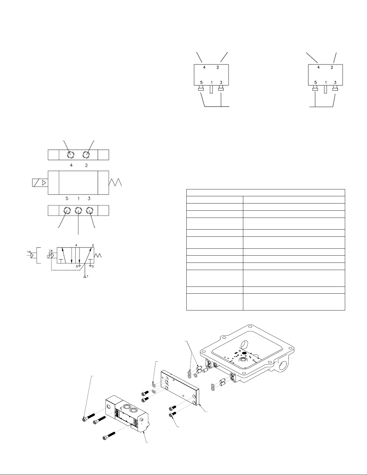
4-Way Spool Valves
The TopWorx™ spool valve is a 5 port, 4-way valve driven by an
internally mounted pilot. The spool valve supply port and work ports
are marked as follows:
PORT TO
ACTUATOR OPEN
EXHAUST OF PORT 4
(WHEN ACTUATOR CLOSES)
(WHEN ACTUATOR OPENS)
SUPPLY
FAIL CLOSED
PORT TO
ACTUATOR CLOSE
EXHAUST OF PORT 2
Spool Valve Assembly
SUPPLY SUPPLY
DOUBLE ACTING ACTUATORS SPRING RETURN ACTUATORS
ALWAYS INSTALL VENTS ALWAYS INSTALL VENTS
Highly Recommended
TopWorx™ highly recommends Locktite 567 brand thread sealant.
Do not use a hard setting pipe compound. If Teon thread seal tape
is used, start the wrap on the second thread from the leading thread
of the tting. This will prevent tape shreds from contaminating the
spool valve seals.
Breathers (AL-M31) should be installed in the exhaust ports to keep
debris from falling into the spool valve and damaging the seals. This
must be addressed prior to installation, or storage.
VALVE SPECIFICATION
ITEM PERFORMANCE
Media Air
Media temperature Min: -40°C (-40°F); Max: 60°C (140°F)
Operational ambient
temperature
Inlet/system pressure Min: 45 PSI (3.1 bar); Max: 150 PSI (10.3 bar)
Operational pressure
differential
Safe working pressure 150 PSI (10.3 bar)
Flow / Cv (Kv) Cv = 0.86 (Kv = 0.74)
Body port connections 1/4” NPT
Allowable leakage External: 2 sccm
Optimal design life 500,000 cycles
Material in contact with
uid
* Refer to the wiring diagram on the inside lid of your product to determine actual
pin out location
Min: -40°C (-40°F); Max: 60°C (140°F)
Min: 45 PSI (3.1 bar); Max: 150 PSI (10.3 bar)
Internal: 10 cc/min max for -15°C to 60°C.
3300 cc/min max for -40°C to -15°C
Body: Aluminium (black anodized) and
Stainless Steel 316L
Internal: Stainless Steel, LT, nitrile, PTFE, Acetal
M5 X 30MM
SCHS (X3)(4MM
HEX WRENCH)
FLAME ARRESTORS & ORINGS (X5)
O-RINGS (X2)
ASCO™ VALVE WITHOUT
MANUAL OVERIDE
M5 X 12MM SCHS (X4)
(4MMHEX WRENCH)
6
ADAPTER PLATE
Page 7
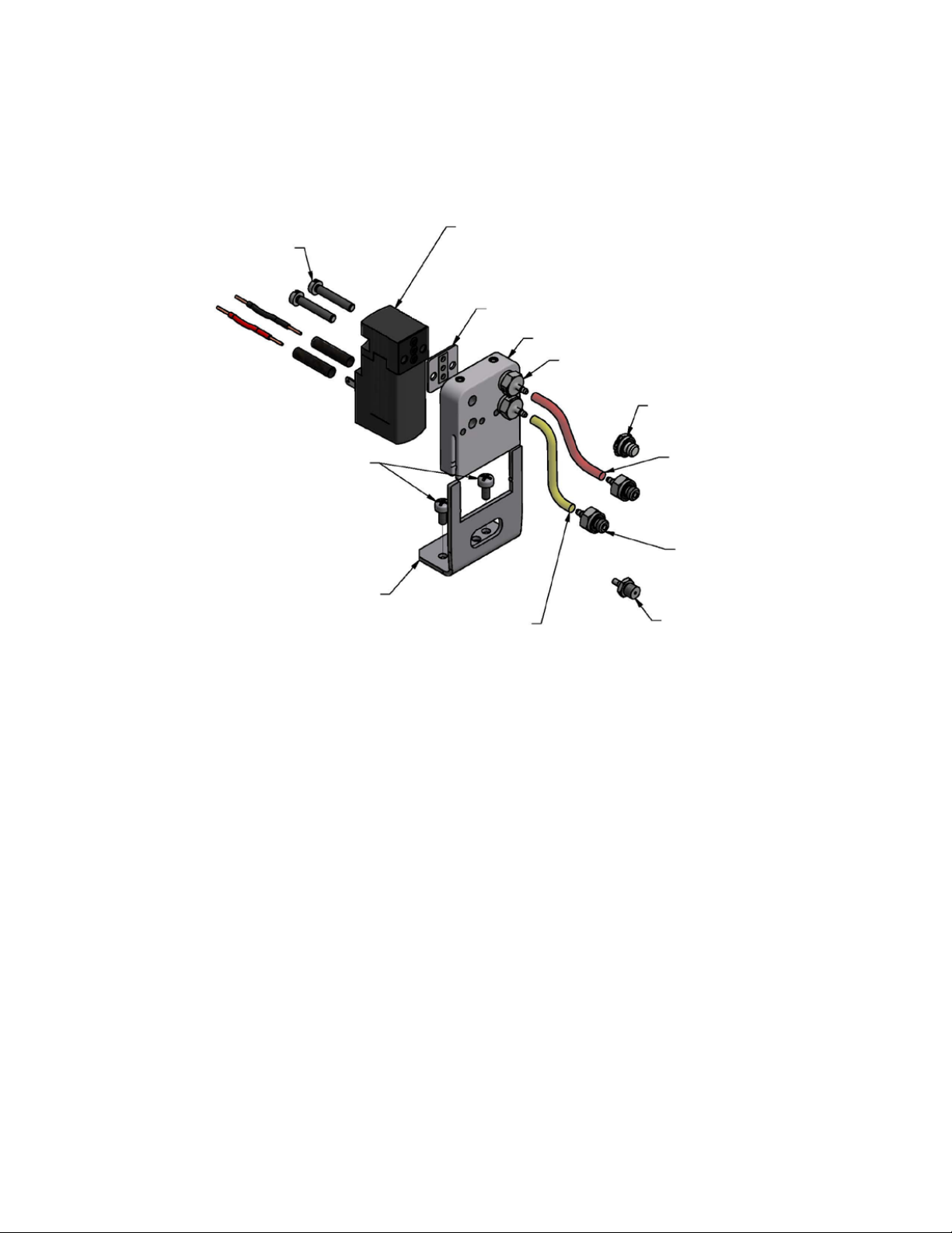
Spool Valves and Pilots
M3 X 18 CHEESE HEAD SCREW
TORQUE TO 20 IN-OZ
SINGLE PILOT ASSEMBLY
PILOT
ASCO™ 302
MINI PIEZO
AMISCO 110 VAC
AMISCO 220 VAC
SEAL AND PLATE
(NOT USED WITH MINI PIEZO)
MANIFOLD
10-32 METAL BARB FITTING
TORQUE TO 60 IN-OZ
10-32 METAL PLUG
4-40 X .25” SEM SCREW
TORQUE TO 100 IN-OZ
BRACKET
YELLOW URETHANE
TUBING (WORK)
RED URRETHANE
TUBING (SUPPLY)
10-32 METAL BARB FITTING
TORQUE TO 60 IN-OZ
ORIFICE TO BE USED IN
EXPLOSION PROOF APPLICATIONS
Page 8
ESD CONVENTIONAL INSTRUCTION AND OPERATION—Fail Closed Valves
Operation: Before operation, the ESD must be calibrated (see Calibration below). After calibration, a Partial Stroke Test (PST) may be
performed (see Partial Stroke Test below). The partial stroke time tolerance range can be selected as 20%, 30% or 40% (see Partial Stroke Time
Tolerance Range Selection below). A single switch (on board and external) is used to perform the calibration, the partial stroke test and the
tolerance range selection. These operations can be initiated from the control room with no need to shut down the entire plant. Nonvolatile
memory stores the calibration value and the selected tolerance range value allowing for retention, even in the event of loss of power. The LED,
both onboard and in the control room, ashes unique visual indicators to signal pass/fail of tests and possible maintenance issues (please see
ESD Conventional Flow Chart and Message Table for ESD Conventional for more details).
*Note that the following instructions assume the valve is FAIL CLOSED and the direction of travel from CLOSED to OPEN is CCW.
Fail Closed
GO™ Switch connection (Prewired) Exte rnal PST but ton (Prew ired)
Valve Pos 1 (Op en) switch NO con tact. Du ring bench te sting only, ad d a
2500 Ohm, 1/2 W res istor for pat h back to DC supp ly via termin al 6.
Valve Pos 1 NC C ontact
Valve Posi tion 1 (Open). COM. T ie it to Valve Posi tion 1 COM 24VDC+
Valve Pos 2 (Clo sed) switc h NO contact . During ben ch testing o nly, add a
2500 Ohm, 1/2 W res istor for pat h back to DC supp ly via termin al 6.
Valve Pos 2 NC C ontact
Valve Posi tion 2(Closed) s witch COM con tact,
wire it ba ck to Terminal 5 24VD C+
Figure 2: Suggested Test Bench Setup for Fail Closed Applications
BLUE
Black
Calibration Switch
CALIBRATION
TopWorx™ ESD
POSITION 2
LED (RED)
CAL SW
LED (AMBER)
POSITION 1
LED (GREEN)
ALARM COM PSI
Power for electronics module 24VDC-
Power for electronics module 24VDC+
Soleno id Pilot or SOV O utput (-)
BL ACK (-)
To Solenoid P ilot or SOV
RE D (+)
Soleno id Pilot or SOV O utput (+)
800mA@24VDC MAX
250mA@125VAC MAX
Option al externa l diagnosti c signal. If wi red, will pas s pulses out
the same a s the LED ashe s for the calib ration diag nostic (pg. #16)
Option al externa l signal COMMO N.
Tie it to th e Valve Pos 1 and 2 COM
Optional external alarm signal.
If wired , will close i f PST calibr ation if pass es.
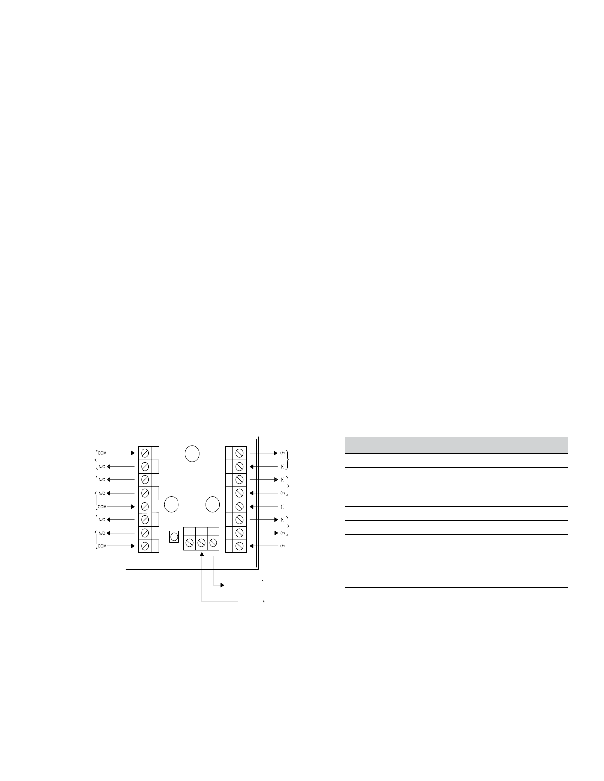
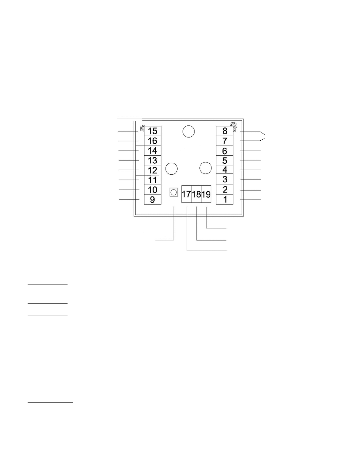
Wiring Connections:
1. Terminals 1 and 4: External power source for switching the solenoid valve. Type and voltage level must match type of solenoid selected.
Typical is 24VDC.
2. Terminals 2 and 3: Output to solenoid pilot or SOV.
3. Terminals 5 and 6: Power for electronics module. 5 MUST be +24VDC and 6 MUST be –24VDC.You can jumper the power from terminals 1
and 4 ifthe Solenoid is rated for 24VDC where a separate 24VDC supply is not available.
4. Terminals 7 and 8: Connection to external calibration and partial stroke test button (if installed). Can be used to remotely trigger PST and
Calibration from aDCS.
5. Terminals 9 and 11: Switch common and normally open connections for valve position 2 limit switch. Typically connected to DCS for limit
switch sensing. Forbench calibration or use in applications where alternate means of sensing valve position are used, these 2 terminals
must still be provided withsource and return. The source and return for the electronics module power can be used, but a 2500 Ohm, 1/2W
resistor MUST be installed betweenterminals 6 and 11 to prevent damage to the limit switch contacts from excess current.
6. Terminals 10 & 13: N/C side of Position 1 and 2 limit switch. Make sure current through switch is limited below maximum rating. If the
system this unit is implemented on is monitoring the N/C side of the switches, a 2500 ohm, 1/2W resistor will need to wired between
terminals 10 and 6, as well terminal 13 and 6 for visual indication. If the system is monitoring the N/O side, neither of these terminals are
used.
7. Terminals 12 and 14: Switch common and normally open connections 1 limit switch. Typically connected to DCS for limit switch sensing.
For benchcalibration or use in applications where alternate means of sensing valve position are used, these 2 terminals must still be
provided with source andreturn. The source and return for the electronics module power can be used, but a 2500 Ohm, 1/2W resistor
MUST be installed between terminals 6and 14 to prevent damage to the limit switch contacts from excess current.
8. Terminals 15 and 16: Prewired to the GO™ Switch. Do not change these connections.
9. Terminals 17, 18 and 19: External PST status signals:
A. Terminal 17: PST status signal. In combination with terminal 18, it forms a dry contact that closes if the PST passes.
B. Terminal 18: 24VDC source terminal for diagnostics and status output signal. Wire this to DCS 24VDC output.
C. Terminal 19: PST diagnostic signal. When wired to a DCS DC I/O input, will deliver a pulse train after PST completes to report any
diagnostic information.
8
Page 9
Partial Stroke Time Tolerance Range Selection:
1. The default partial stroke time tolerance range is set to 20%. This value can be selected as 20%, 30% or 40% anytime.The value will be
recorded in the EEPROM (memory) of the micro controller.
2. Press and hold the push button for ten to fteen seconds to set the partial stroke time tolerance range to 20%.If the value is saved to
memory successfully, the LED and diagnostic relay will ash message code 5-1.
3. Press and hold the push button for within fteen to twenty seconds to set the partial stroke time tolerance range to 30%.If the value is
saved to memory successfully, the LED and diagnostic relay will ash message code 5-2.
4. Press and hold the push button for more than twenty seconds to set the partial stroke time tolerance range to 40%.If the value is saved to
memory successfully, the LED and diagnostic relay will ash message code 5-3.
5. If there is a writing value to memory failure, the LED and diagnostic relay will ash message code 6-6. The Pass/Fail relay willbe turned OFF.
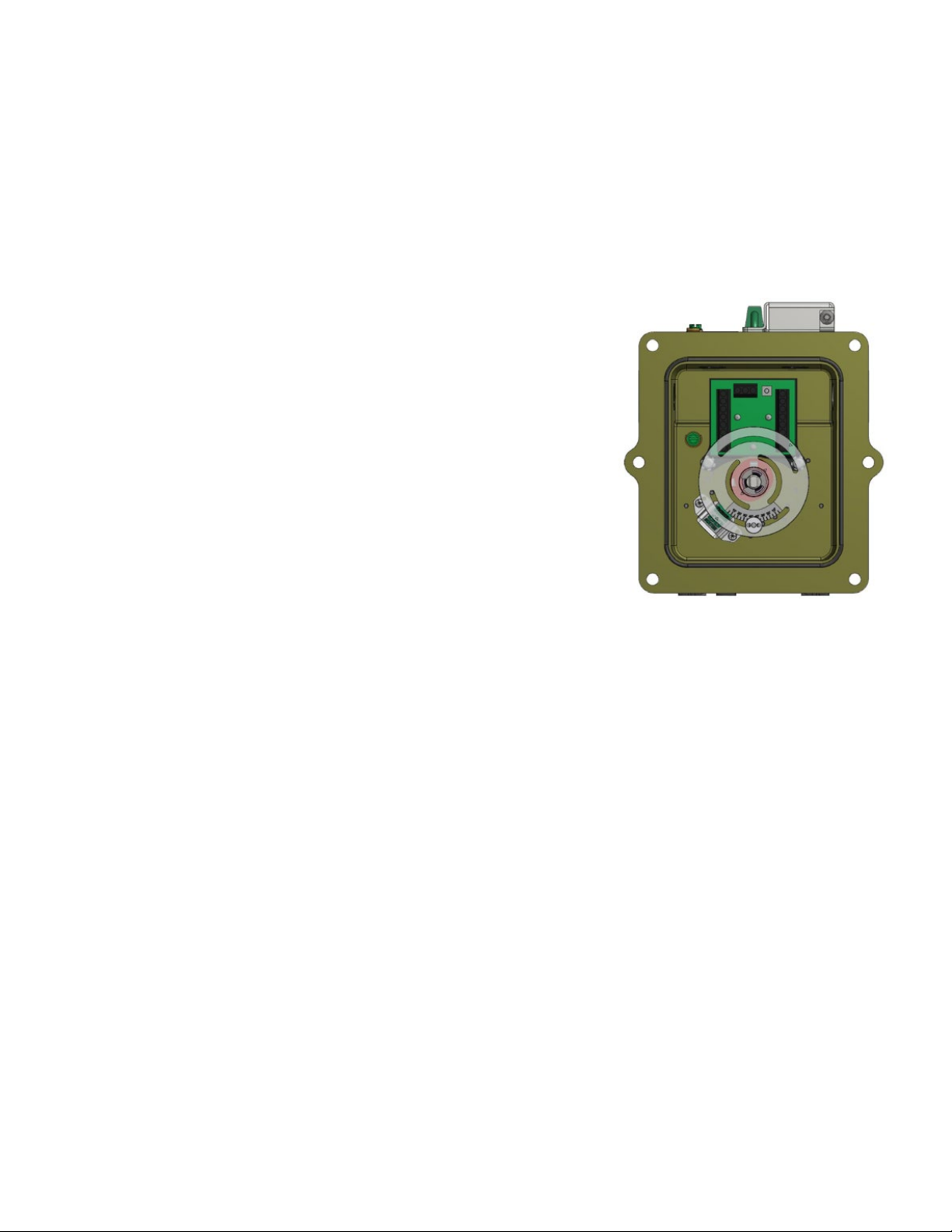
Figure 3
Hardware Conguration:
1. Ensure that the valve is in the OPEN position (the green position 1 LED should be
illuminated.)
2. Refer to Fig. 3 which shows the correct orientation of the GO™ Switch target and sensor
camsfor FAIL CLOSED valves.
3. If the unit conforms to this conguration, you may proceed to calibration. If not,
completeHardware Conguration steps 4-7.
4. Lift the target wheel and rotate it such that the magnet is counterclockwise from the
GO™ Switch.
5. Loosen and slide the magnet in the target wheel so as to position it approximately one
inch from theedge of the GO™ Switch. Tighten to 20 in-oz.
6. Lift up on the upper cam and rotate it such that it is squarely aligned to the front of the
electronicsmodule. The green light on the module should come on.
7. Press down on the lower cam and rotate it such that it is 90º counter clockwise from the
electronics module.
Calibration:
1. Before performing calibration, make certain the valve is fully open (the green position 1 LED should be illuminated,) and the target button
is set to the properpartial position.
*NOTE: If the valve is not fully open, the test will abort and the LED and diagnostic relay will ash message code 7- 7 indicating
thatthe valve is not fully open. The Pass/Fail relay will be turned OFF.
2. Press and hold the calibration button on board for ve to ten seconds.
3. The activation relay will be turned ON to initiate valve closing.
4. The valve will move until the GO™ Switch detects the partial stroke position.
5. The GO™ Switch will send feedback indicating that the predetermined position is reached.
6. The time required to move the valve from the “fully open position” to the “partially open position” is the partial stroke time of the valve.
The acceptable timeranges are from fty milliseconds to thirty seconds. This “partial stroke calibration time” will be recorded in the
EEPROM (memory) of the micro controller.EEPROM will retain the value until your next calibration.
7. If the calibration is successful, the Pass/Fail relay will be turned ON and both the LED and diagnostic relay will ash message code 3-3.
8. After the LED ashes code for three cycles, both the LED and diagnostic relay will be steady, signifying that the calibration is complete.
Reset of the ashingLED and the diagnostic relay may be performed at anytime while the LED is ashing by pressing the calibration button.
Page 10

Partial Stroke Test:
1. Before performing the Partial Stroke Test (PST), make certain the valve is fully open.
* NOTE: If the valve is not fully open, the test will abort and the LED and diagnostic relay will ash message code 7-7
indicating that the valve isnot fully open. The Pass/Fail relay will be turned OFF.
2. If using the onboard module calibration button, press the button and hold it for more than half a second and less than ve seconds.
If using the optional external PST button, push rmly once.
3. The activation relay will be turned ON to initiate valve closing.
4. The valve will move until the GO™ Switch detects the partial stroke position.
5. The time required to move the valve to the partial stroke position will be compared against the “partial stroke calibration time”
value stored in EEPROM (memory). The acceptable time ranges from “(1-tolerance range value) x partial stroke calibration time”
to”(1+tolerance range value) x partial stroke calibration time”. For example, if the partial stroke calibration time is 6 seconds and the
tolerance range value is 20%, the acceptable PST time ranges are from 4.8 to 7.2 seconds.
6. If the time required for moving the valve to the Partial Stroke position is outside the acceptable range of the “partial stroke
calibration time”, the test will beaborted, indicating valve failure. The Pass/Fail relay will remain OFF and both the LED and
diagnostic relay will ash message code 5-5 if the valve has moved. If the valve has not moved, the Pass/Fail relay will remain OFF
and both the LED and diagnostic relay will ash code 4-4.
CAUTION: Beforerecalibration, make sure any failure codes are addressed (see table pg.#16).
7. If the time required is within the acceptable range, the Pass/Fail relay will be turned ON and both the LED and Diagnostic Relay will
ash message code 2-2 .
8. After the LED ashes code for three times, both the LED and diagnostic relay will be steady, signifying that the Partial Stroke Test is
complete.
* Note: Partial Stroke Time Tolerance Range Selection, Calibration or Partial Stroke Test cannot be performed when the LED is
ashing. Before rerunning the test, please wait for the LED to become steady or clear it by pressing the button.
10
Page 11

ESD Calibration/PST Flow Chart—Fail Closed Valves
Apply power
NO
NO
Is partial stroke
position reached?
YES
Is minimum allewed
time (50ms) passed?
YES
Valve opens
LED displays
valve is not
calibrated code
1-1 pass/fail
relay state 0
Is memory ok?
NO
Is button
releasedbefore
5 seceonds?
YES
Begin partial stroke test
YES
Is valve fully open? Is valve fully open?
YES YES
Is device calibrated?
YES
Is stored calibrated value
for partial stroke time
within range?
YES
Valve closes
NO
NO
Has valve moved?
LED displays
valve closing
time failure code
5-5 pass/fail
relay state 0
NO
NO NO
Valve opens
NO
Is calibrartted
time passed?
Valve opens
NO
YES
LED displays
valve has not
moved code
4-4 pass/fail
relay state 0
Write uncalibrated status to momory
NO
Is maximum
allowed time
(30s) passed?
YES
Valve opens Valve opens
LED displays
valve is not
fully open code
7-7 pass/fail
relay state 0
Is device calibrated?
Is button pressed and held
for at least 0.5 seconds?
Is button
released before
10 seceonds?
Begin partial stroke calibration
Writing status value to
memory successful?
Valve closes
LED displays
valve closing
time failure code
5-5 pass/fail
relay state 0
YES
YES
YES
YES
YES
NO
stroke position
NO
allowed time (50ms)
calibrated value
NO
Is partial
reached?
YES
Is minimum
passed?
YES
Is writing
to memory
successful?
YES
NO
NO
Is button
released before
15 seceonds?
YES
Set partial stroke time
tolerance range to 20%
NO
NO
NO
LED displays
writing error code 6-6
pass/fail relay state 0
LED displays memory error
continuous fast ashing
Pass/fail relay state 0
NO
released before
tolerance range to 30%
Is writing
tolerance
range value to
memory
successful?
YES
Is writing
tolerance
range value to
memory
successful?
Is button
20 seceonds?
Set partial stroke time
YES YES
error code 6-6 pass/fail
NO
YES
Set partial stroke time
tolerance range to 40%
NO
LED displays writing
relay state 0
range value to
Is button
released?
YES
Is writing
tolerance
memory
successful?
NO
LED displays
partial stroke test
complete code 2-2
for all tolerance range
pass/fail relay state 1
LED displays
calibrarion
complete code
3-3 pass/fail
relay state 1
LED displays
range set to
20% complete
code 5-1
LED displays
range set to
30% complete
code 5-2
LED displays
range set to
40% complete
code 5-3
Page 12

ESD CONVENTIONAL INSTRUCTION AND OPERATION—Fail Open Valves
Operation:
For operation, the ESD must be calibrated (see Calibration below). After calibration, a partial stroke test may be performed (see Partial
Stroke Test below). The partial stroke time tolerance range can be selected as 20%, 30% or 40% (see Partial Stroke Time Tolerance Range
Selection below). A single switch (on board and external) is used to perform the calibration, the partial stroke test and the tolerance range
selection. These operations can be initiated from the control room with no need to shut down the entire plant. Nonvolatile memory stores the
calibration value and the selected tolerance range value allowing for retention, even in the event of loss of power. The LED, both onboard and
in the control room, ashes unique visual indicators to signal pass/fail of tests and possible maintenancei ssues (please see ESD Conventional
Flow Chart and Message Table for ESD Conventional on pg.#15 for more details).
*Note that the following instructions assume the valve is FAIL OPEN and the direction of travel from CLOSED to OPEN is CCW.
Fail Open
GO™ Switch connection (Prewired)
Valve Pos 1 (Clo sed) switc h NO contact , needs path
(Add a 2500 O hm 1/2W resistor to pa th)
Valve Posi tion 1(Closed) COM . Tie it to Valve P osition 1 COM
Valve Pos 2 (Op en) switch NO con tact, ne eds path back t o DC
Valve Posi tion 2(Open) swi tch COM contac t, wire it ba ck to
Figure 4:
Suggested Test Bench Setup for
Fail Open Applications
(Add a 2500 O hm 1/2W resistor to pa th)
BLUE
Black
back to DC
Valve Pos 1 NC C ontact
Valve Pos 2 NC C ontact
Terminal 5
CALIBRATION
LED (AMBER)
TopWorx™ ESD
POSITION 2
LED (RED)
CAL SW
Calibration
Switch
POSITION 1
LED (GREEN)
ALARM COM PSI
Exte rnal PST but ton (Prew ired)
Power for electronics module 24VDC-
Power for electronics module 24VDC+
Soleno id Pilot or SOV O utput (-)
BL ACK (-)
RE D (+)
Soleno id Pilot or SOV O utput (+)
800mA@24VDC MAx
250mA@125VAC Max
Option al externa l diagnosti c signal. If wi red, will pas s pulses out th e same as
the LED a shes for the ca libration d iagnostic ( pg.#16)
Option al externa l signal COMMO N.
Tie it to th e Valve Pos 1 and 2 COM
Optional external alarm signal. If wired, will close if PST calibration passes.
Wiring Connections:
1. Terminals 1 and 4: External power source for switching the solenoid valve. Type and voltage level must match type of solenoid selected.
Typical is 24VDC.
2. Terminals 2 and 3: Output to solenoid pilot or SOV.
3. Terminals 5 and 6: Power for electronics module. 5 MUST be +24VDC and 6 MUST be –24VDC.You can jumper the power from
terminals 1 and 4 if the Solenoid is rated for 24VDC where a separate 24VDC supply is not available.
4. Terminals 7 and 8: Connection to external calibration and partial stroke test button (if installed). Can be used to remotely trigger PST and
Calibration from a DCS.
5. Terminals 9 and 11: Switch common and normally open connections for valve position 2 limit switch. Typically connected to DCS for
limit switch sensing. For bench calibration or use in applications where alternate means of sensing valve position are used, these 2
terminals must still be provided with source and return. The source and return for the electronics module power can be used, but
a 2500 Ohm, 1/2W resistor MUST be installed between terminals 6 and 11 to prevent damage to the limit switch contacts from
excess current.
6. Terminals 10 & 13: N/C side of Position 1 and 2 limit switch. Make sure current through switch is limited below maximum rating. If
the system this unit is implemented on is monitoring the N/C side of the switches, a 2500 ohm, 1/2W resistor will need to wired
between terminals 10 and 6, as well terminal 13 and 6 for visual indication. If the system is monitoring the N/O side, neither of
these terminals are used.
7. Terminals 12 and 14: Switch common and normally open connections 1 limit switch. Typically connected to DCS for limit switch sensing.
For bench calibration or use in applications where alternate means of sensing valve position are used, these 2 terminals must still
be provided with source and return. The source and return for the electronics module power can be used, but a 2500 Ohm, 1/2W
resistor MUST be installed between terminals 6 and 14 to prevent damage to the limit switch contacts from excess current.
8. Terminals 15 and 16: Prewired to the GO™ Switch. Do not change these connections..
9. Terminals 17, 18 and 19: External PST status signals:
A. Terminal 17: PST status signal. In combination with terminal 18, it forms a dry contact that closes if the PST passes..
B. Terminal 18: 24VDC source terminal for diagnostics and status output signal. Wire this to DCS 24VDC output.
C. Terminal 19: PST diagnostic signal. When wired to a DCS DC I/O input, will deliver a pulse train after PST completes to report any
diagnostic information.
12
Page 13

Partial Stroke Time Tolerance Range Selection:
1. The default partial stroke time tolerance range is set to 20%. This value can be selected as 20%, 30% or 40% anytime.The value will be
recorded in the EEPROM (memory) of the micro controller.
2. Press and hold the push button for ten to fteen seconds to set the partial stroke time tolerance range to 20%.If the value is saved to
memory successfully, the LED and diagnostic relay will ash message code 5-1.
3. Press and hold the push button for within fteen to twenty seconds to set the partial stroke time tolerance range to 30%.If the value is
saved to memory successfully, the LED and diagnostic relay will ash message code 5-2.
4. Press and hold the push button for more than twenty seconds to set the partial stroke time tolerance range to 40%. If the value is saved
tomemory successfully, the LED and diagnostic relay will ash message code 5-3.
5. If there is a writing value to memory failure, the LED and diagnostic relay will ash message code 6-6. The Pass/Fail relay will be turned OFF.
Figure 5
Hardware Conguration:
1. Ensure that the valve is in the CLOSED position (the green position 1 LED should be
illuminated).
2. Refer to Fig. 5 which shows the correct orientation of the GO™ Switch target and sensor
cams for FAILOPEN valves.
3. If the unit conforms to this conguration, you may proceed to calibration. If not,
complete HardwareConguration steps 4-7.
4. Lift the target wheel and rotate it such that the magnet is counterclockwise from the
GO™ Switch.
5. Loosen and slide the magnet in the target wheel so as to position it approximately one
inch from the edgeof the GO™ Switch. Tighten to 20in-oz.
6. Lift up on the upper cam and rotate it such that it is squarely aligned to the front of the
electronicsmodule. The green light on the module should come on.
7. Press down on the lower cam and rotate it such that it is 90º counter clockwise from the
electronics module.
Calibration:
1. Before performing calibration, make certain the valve is fully closed (the green position 1 LED should be illuminated,) and the target
button is set to the properpartial position.
*NOTE: If the valve is not fully closed, the test will abort and the LED and diagnostic relay will ash message code 7-7 indicating
that the valve is not fully closed. The Pass/Fail relay will be turned OFF.
2. Press and hold the calibration button on board for ve to ten seconds.
3. The activation relay will be turned ON to initiate valve closing.
4. The valve will move until the GO™ Switch detects the partial stroke position.
5. The GO™ Switch will send feedback indicating that the predetermined position is reached.
6. The time required to move the valve from the “fully closed position” to the “partially closed position” is the partial stroke time of the
valve. The acceptable timeranges are from fty milliseconds to thirty seconds. This “partial stroke calibration time” will be recorded in the
EEPROM (memory) of the micro controller.EEPROM will retain the value until your next calibration.
7. If the calibration is successful, the Pass/Fail relay will be turned ON and both the LED and diagnostic relay will ash message code 3-3.
8. After the LED ashes code for three times, both the LED and diagnostic relay will be steady, signifying that the calibration is complete.
Reset of the ashingLED and the diagnostic relay may be performed at anytime while the LED is ashing by pressing the calibration button.
Page 14

Partial Stroke Test:
1. Before performing the Partial Stroke Test (PST), make certain the valve is fully open.
* NOTE: If the valve is not fully open, the test will abort and the LED and diagnostic relay will ash message code 7-7
indicating that the valve isnot fully open. The Pass/Fail relay will be turned OFF.
2. If using the onboard module calibration button, press the button and hold it for more than half a second and less than ve seconds.
If using the optional external PST button, push rmly once.
3. The activation relay will be turned ON to initiate valve closing.
4. The valve will move until the GO™ Switch detects the partial stroke position.
5. The time required to move the valve to the partial stroke position will be compared against the “partial stroke calibration time”
value stored in EEPROM (memory). The acceptable time ranges from “(1-tolerance range value) x partial stroke calibration time”
to”(1+tolerance range value) x partial stroke calibration time”. For example, if the partial stroke calibration time is 6 seconds and the
tolerance range value is 20%, the acceptable PST time ranges are from 4.8 to 7.2 seconds.
6. If the time required for moving the valve to the Partial Stroke position is outside the acceptable range of the “partial stroke
calibration time”, the test will beaborted, indicating valve failure. The Pass/Fail relay will remain OFF and both the LED and
diagnostic relay will ash message code 5-5 if the valve has moved. If the valve has not moved, the Pass/Fail relay will remain OFF
and both the LED and diagnostic relay will ash code 4-4.
CAUTION: Beforerecalibration, make sure any failure codes are addressed (see table pg.#16).
7. If the time required is within the acceptable range, the Pass/Fail relay will be turned ON and both the LED and Diagnostic Relay will
ash message code 2-2 .
8. After the LED ashes code for three times, both the LED and diagnostic relay will be steady, signifying that the Partial Stroke Test is
complete.
* Note: Partial Stroke Time Tolerance Range Selection, Calibration or Partial Stroke Test cannot be performed when the LED is
ashing. Before rerunning the test, please wait for the LED to become steady or clear it by pressing the button.
14
Page 15

ESD Calibration/PST Flow Chart—Fail Closed Valves
Apply power
NO
NO
Is partial stroke
position reached?
YES
Is minimum allewed
time (50ms) passed?
YES
Valve closes
LED displays
valve is not
calibrated code
1-1 pass/fail
relay state 0
Is memory ok?
YES
NO
Is button
releasedbefore
5 seceonds?
YES
Begin partial stroke test
YES
Is valve fully closed? Is valve fully closed?
YES YES
Is device calibrated?
YES
Is stored calibrated value
for partial stroke time
within range?
YES
Valve opens
NO
NO
Has valve moved?
LED displays
valve opening
time failure code
5-5 pass/fail
relay state 0
NO
NO NO
Valve closes
NO
Is calibrartted
time passed?
Valve closes
NO
YES
LED displays
valve has not
moved code
4-4 pass/fail
relay state 0
Write uncalibrated status to momory
NO
Is maximum
allowed time
(30s) passed?
YES
Valve closes Valve closes
LED displays
valve is not
fully closed code
7-7 pass/fail
relay state 0
Is device calibrated?
YES
Is button pressed and held
for at least 0.5 seconds?
YES
Is button
released before
10 seceonds?
YES
Begin partial stroke calibration
Writing status value to
memory successful?
YES
Valve opens
NO
NO
LED displays
valve opening
time failure code
5-5 pass/fail
relay state 0
NO
NO
Is partial
stroke position
reached?
YES
Is minimum
allowed time (50ms)
passed?
YES
Is writing
calibrated value
to memory
successful?
YES
writing error code 6-6
pass/fail relay state 0
NO
NO
Is button
released before
15 seceonds?
YES
Set partial stroke time
tolerance range to 20%
NO
range value to
NO
LED displays
LED displays memory error
continuous fast ashing
Pass/fail relay state 0
NO
Is writing
tolerance
memory
successful?
Is button
released before
20 seceonds?
Set partial stroke time
tolerance range to 30%
YES
Is writing
tolerance
range value to
memory
successful?
NO
Is button
released?
YES
Set partial stroke time
tolerance range to 40%
NO
YES YES
LED displays writing
error code 6-6 pass/fail
relay state 0
YES
Is writing
tolerance
range value to
memory
successful?
NO
LED displays
partial stroke test
complete code 2-2
for all tolerance range
pass/fail relay state 1
LED displays
calibrarion
complete code
3-3 pass/fail
relay state 1
LED displays
range set to
20% complete
code 5-1
LED displays
range set to
30% complete
code 5-2
LED displays
range set to
40% complete
code 5-3
Page 16

Message Table for ESD Conventional
LED Status Flash
Code
Solid ON Unit operating correctly No action required
1 - 1 Device not calibrated Need to perform the calibration procedure before the partial stroke test
2 - 2
3 - 3 Calibration completed No action required
4 - 4
5 - 1
5 - 2
5 - 3
5 - 5 Partial stroke test failed
6 - 6 Module memory error Contact factory
7 - 7
Continuous fast
ashing
Diagnostic Relay Message Problem Cause / Solution
Partial stroke test passed within
tolerance range
Valve has not moved during
partial stroke test
Partial stroke time tolerance
range is set to 20%
Partial stroke time tolerance
range is set to 30%
Partial stroke time tolerance
range is set to 40%
Valve is not fully at the required
open or closed position
Hardware failure Contact factory
No action required
Possible causes include:
1) The valve is stuck
2) The shaft is broken
No action required
No action required
No action required
The valve did not reach the partial stroke position within the allotted time. Possible causes include:
1) The valve is stuck or sluggish
2) The GO™ Switch target for the partial stroke position is set incorrectly
3) The shaft is broken
Unit cannot calibrate or run a partial stroke test without the valve starting in the required open or
closed position. Check the following:
1) Air supply to actuator
2) Solenoid is powered
3) Cam setting for fail open or fail closed valves as required
Electrical Ratings
Current/Voltage
Open/Closed Indication 0.25A@24VDC w/5V drop
Dry Contact Rating Minimum Current Through Switch
Module Voltage 18-28VDC
Module Current 50mA (MAX)
Pilot Current (Standard) 20mA
PST Feedback Relays 800mA@24VDC MAX
Solenoid Pilot/SOV
Maximum PowerRating
0.25A@120VAC w/5V drop
Contacts: 5 mA
250mA@125VAC MAX
800mA@24VDC MAX
250mA@125VAC MAX
Diagnostic Relay and Pass/Fail Relay Outputs:
The diagnostic relay outputs the status ash code as shown in the
Message Table Above.
DIAGNOSTIC RELAY
TIMING CHART
EXAMPLE OF A 2-2 RESPONSE
The Pulse Train will repeat 3 times. In order to use this diagnostic
relay output, control logic should count the number of positive
transitions in order to get the message number. Clear the count
register in the logic when you see a logic low (open) for more than
one second. The Pulse Train can be reset anytime by activating the
Calibration Switch or the PST/Calibration Activation Input.
16
Page 17

Pass/Fail Relay:
The Pass/Fail Relay indicates whether the PST passed or failed. In this
example the relay is closed (high) from the last successful Partial
Stroke Test.
PASS / FAIL RELAY
TIMING CHART
PARTIAL STROKE TEST
SWITCH / ACTIVATION
(USER INITIATED)
PASS / FAIL RELAY
(HIGH = CLOSED)
When the Partial stroke test button is pressed for less than 5 seconds
the test begins and the Pass/Fail Relay opens (low). The Pass/Fail
Relay closes again once the unit passes a Partial Stroke Test.
Hardware Fault Tolerance: HFT = 0
Device Type: Type A
Systematic Capability: SC3 - SIL3 Capable
Useful Life: 10 years
The proof test procedure should verify the ESD valve controller allows
the ESD valve to function 100% on command, and that any failures
related to the valve, actuator or partial stroke test function are
revealed. The partial stroke test should be preformed monthly.
Special Conditions of Safe Use (All installations)
Clean only with a damp cloth to prevent possibility of
electrostatic discharge.
For Explosion Proof installations, the internal ground connection shall
be used and the external ground connection, if supplied in addition,
is supplemental bonding allowed where local authorities permit, or is
required.
When installing with a third party listed nipplemount solenoid, it is
the responsibility of the installer to provide ttings, and apparatus,
suitable for the area classication in accordance with the National
Electrical Code.
All cable entry devices or conduit stopping boxes shall be certied
in type of explosion protection ‘d’, suitable for the conditions of use
and correctly installed.
The IIC enclosures are excluded from use in Carbon disulphide
atmospheres.
The air pressure to the valve block, when tted, shall not exceed 7
bar.
Preventative Maintenance
TopWorx™ are designed to operate for one million cycles without
servicing. Call the factory when you are approaching this milestone
for a preventative maintenance kit and instructions.
Personal preforming maintenance and testing on the product shall
be competent to do so.
Page 18

Dimensions and Materials: TopWorx™ DXP
Cast aluminum bracket is recommended for installation with SS 8553 valve in vibrating environment.
Enclosure Cast A360 aluminum with dichromate
Fasteners 304 Stainless Steel standard
Shaft 304 Stainless Steel standard
Shaft Bushing Oilite Bronze
Indicator Dome Polycarbonate, UV F1 rated
Seals O -ring seals available in:
Enclosure Housing Bolts 8 ft.-lbs [10.8 N·m] +/-10%
Indicator Dome Screws 320 in-oz. [2.3 N·m] +/-10%
Bottom Mounting Holes 10 ft.-lbs [13.6 N·m] +/-10%
SHAFT TYPE OPTIONAL
SEE SHAFT DETAIL SECTION
MINIMUM 2.25” (63.5) REQUIRED CLEARANCE
IN ORDER TO DISENGAGE THE SHAFT FROM THE LID BUSHING
AND REMOVE LID WHERE OPTIMUM CONDITIONS APPLY
MATERIALS OF CONSTRUCTION
conversion coating inside & out, epoxy
coated exterior rated for 250 hrs. salt
spray per ASTM B117
316 Stainless Steel optional
316 Stainless Steel optional
Buna, & Silicone
Fastener Torque Specications
18
Page 19

Dimensions and Materials: TopWorx™ DXP - Flameproof Ex d IIC
Cast aluminum bracket is recommended for installation with SS 8553 valve in vibrating environment.
IN ORDER TO DISENGAGE THE SHAFT FROM THE LID BUSHING
AND REMOVE LID WHERE OPTIMUM CONDITIONS APPLY
SHAFT TYPE OPTIONAL
SEE SHAFT DETAIL SECTION
MINIMUM 2.25” (63.5) REQUIRED CLEARANCE
MOUNTING SURFACE
Enclosure Cast A360 aluminum with dichromate
Fasteners 304 Stainless Steel standard
Shaft 304 Stainless Steel standard
Shaft Bushing Oilite Bronze
Indicator Dome Polycarbonate, UV F1 rated
Seals O -ring seals available in:
Enclosure Housing Bolts 8 ft.-lbs [10.8 N·m] +/-10%
Indicator Dome Screws 320 in-oz [2.3 N·m] +/-10%
Bottom Mounting Holes 10 ft-lbs [13.6 N·m] +/-10%
MATERIALS OF CONSTRUCTION
conversion coating inside & out, epoxy
coated exterior rated for 250 hrs. salt
spray per ASTM B117
316 Stainless Steel optional
316 Stainless Steel optional
Buna, & Silicone
Fastener Torque Specications
VALVE TYPE OPTIONAL
SEE INTEGRATED PNEUMATIC
CONTROL VALVES SECTION
Page 20

Dimensions and Materials: TopWorx™ DXS
Cast aluminum bracket is recommended for installation with SS 8553 valve in vibrating environment.
IN ORDER TO DISENGAGE THE SHAFT FROM THE LID BUSHING
AND REMOVE LID WHERE OPTIMUM CONDITIONS APPLY
SHAFT TYPE OPTIONAL
SEE SHAFT DETAIL SECTION
MINIMUM 2.5” (63.5) REQUIRED CLEARANCE
MOUNTING SURFACE
OPTIONAL CONDUIT ENTRIES USED
ONLY WHEN 4 ENTRIES ARE SPECIFIED
OPTIONAL CONDUIT ENTRIES
BOTH SIDES
MATERIALS OF CONSTRUCTION
Enclosure Cast 316 Stainless Steel
Fasteners 304 Stainless Steel standard
316 Stainless Steel optional
Shaft 304 Stainless Steel standard
316 Stainless Steel optional
Shaft Bushing N/A
Indicator Dome Polycarbonate, UV F1 rated
Seals O -ring seals available in:
Buna, & Silicone
Fastener Torque Specications
Enclosure Housing Bolts 8 ft.-lbs [10.8 N·m] +/-10%
Indicator Dome Screws 320 in-oz. [2.3 N·m] +/-10%
Bottom Mounting Holes 10 ft.-lbs [13.6 N·m] +/-10%
20
VALVE TYPE OPTIONAL
SEE INTEGRATED PNEUMATIC
CONTROL VALVES SECTION
Page 21

Interior and Indicator Assemblies
Interior Assembly
24 VDC PILOT
ESD MODULE CONTAINS (2) REED
RELAYS FOR FULL OPEN/CLOSED
INDICATION PLUS TIMER CIRCUIT
TARGET WHEEL
UPPER CAM
LOWER CAM
ENCLOSURE
DXP TROPICALIZED ALUMINUM
DXS 316 STAINLESS STEEL
TARGET MAGNET
CAM TARGET
MODEL 35 GO SWITCH TO SET
PARTIAL STROKE POSITION
VALVE
ANODIZED ALUMINUM
316 STAINLESS STEEL
0.86 Cv 1/4” NPT PORTS
3.7 Cv 1/2” NPT PORTS
PAD LOCK PROVIDED
BY END USER
OPTIONAL EXTERNAL PUSH PIEZO SWITCH
WITH LOCKING SHIELD FOR INITIATING
THE PARTIAL STROKE PROCEDURE
Page 22

Certications & Approvals
PESO
Ex d IIC T* Gb or Ex d IIB+H2 T* Gb; Ex tb IIC T* Db IECEx SIR 07.0093X / Sira 07ATEX1273X USL/CNL Class I,
Div 1, GrCD; Class II, Div 1, GrEFG UL File E125326
EAC RU C-US, M1062.B0027
KOSHA 19-GA4B0-0179X, 19-GA4BO-0180X & 19-GA4BO-0178X
NEPSI GY18.1386X
InMetro UL-BR 18.0096X
PESO P433642
Ex e MB IIC T* Gb; Ex tb IIIC T* Db
IECEx SIR 09.0088X / Sira 09ATEX3209X (DXR)
Ex nA nC IIC T* Gc; Ex tb IIIC T* Dc
USL/CNL Class I, Div 2, GrABCD; Class II, Div 2, GrFG UL
File E125326
USL/CNL General Purpose UL
File E359150
Environmental Ratings: Type 4, 4X; IP 66/67
Conformance to Directives: ATEX 2014/34/EU, EMC 2014/30/EV, LVD 2014/35/EO
*Operating and Ambient temperature ratings vary depending on bus/sensor option(s), reference certicate for specic markings available.
Consult factory for certication questions or to request a custom product.
22
Page 23

Page 24

24
Page 25

Safe Use
User instructions (in compliance with ATEX 2014/34/EU Directive, Annex II, 1.0.6)
Instructions for safe selection, installation, use, maintenance and repair
1. The equipment may be used in zones 1 or 2.
2. The equipment may be used in the presence of ammable gases and vapors with apparatus groups IIC or IIB or IIA and with temperature
classes T3, T4, T5 or T6.
3. The equipment is certied for use in ambient temperatures in the range of -50°C to +60°C and should not be used outside this range.
(NOTE: Ambient temperature range may change according to protection method)
4. The equipment is to be installed by suitably trained personnel in accordance with the applicable code of practice
(typically IEC 60079-14)
5. Under certain extreme circumstances, the plastic cover over the valve position indicator may generate an ignition-capable level of
electrostatic charge. Therefore, particularly in the event of an installation in zone 0, the equipment shall not be installed in a location
where the external conditions are conducive to the build-up of electrostatic charge, e.g. wind-blown dust, etc. Additionally the equipment
shall only be cleaned with a damp cloth.
6. Periodic inspection of the equipment and system should be performed by suitably trained personnel in accordance with the applicable
code of practice (typically IEC 60079-17) to ensure it is maintained in a satisfactory condition.
7. The equipment does not require assembly or dismantling.
8. The equipment is not intended to be repaired by the user. Repair of the equipment is to be carried out by the manufacturer, or their
approved agents, in accordance with the applicable code of practice.
Special Conditions of Safe Use (All installations)
Clean only with a damp cloth to prevent possibility of electrostatic discharge.
For Explosion Proof installations, the internal ground connection shall be used and the external ground connection, if supplied in addition, is
supplemental bonding allowed where local authorities permit, or is required.
When installing with a third party listed nipple-mount solenoid, it is the responsibility of the installer to provide ttings, and apparatus,
suitable for the area classication in accordance with the National Electrical Code.
All cable entry devices or conduit stopping boxes shall be certied according to protection type and suitable for the conditions of use and
correctly installed.
The IIC enclosures are excluded from use in carbon disulphide atmospheres.
The air pressure to the valve block, when tted, shall not exceed 10.0bar.
Special Conditions or Safe Use (Flameproof Installations)
1. The IIC enclosures are excluded from use in carbon disulphide atmospheres.
2. The air pressure to the valve block, when tted, shall not exceed 10.0 bar.
3. For ambient temperatures above 110ºC, the degrees of ingress protection IP66 and IP67 are not endorsed.
4. The slotted hexagonal head cover screws are not of standard form; they shall only be replaced with identical screws sourced from the
equipment manufacturer.
5. The hexagonal head cover screws are to be replaced only with stainless steel 304, grade A2-70 or A4-80 screws to ISO 35061.
6. Periodic inspection of the equipment and system should be performed by suitably trained personnel in accordance with the applicable
code of practice (typically IEC 60079-17) to ensure it is maintained in a satisfactory condition.
7. Cover fasteners are to be tightened to a torque valve of 10.85Nm (8 ft./lbs) minimum.
Page 26

Notes:
26
Page 27

Page 28

GLOBAL SUPPORT OFFICES
North America
3300 Fern Valley Road
Louisville, Kentucky 40213 USA
T. +1 502 969 8000
info.topworx@emerson.com
Asia-Pacific
Asia Pacic Pte Ltd - TopWorx
c/o ASCO ASIA
BLK4008, Ang Mo Kio Avenue
10 #04-17/22, Techplace 1
Singapore 569625
Europe
Horseld Way
Bredbury Industrial Estate
Stockport SK6 2SU UK
T. +44 0161 406 5155
info.topworx@emerson.com
T. +65 6891 7550
info.topworx@Emerson.com
Middle East
P.O. Box 17033
Jebel Ali Free Zone
Dubai 17033
United Arab Emirates
T. +971 4 811 8283
Africa
24 Angus Crescent
Longmeadow Business Estate
East Modderfontein
Gauteng South Africa
T. +27 11 451 3700
info.topworx@emerson.com
For comprehensive information on our company, capabilities, and products –
including model numbers, data sheets, specications, dimensions, and certications:
Visit us: Emerson.com/TOPWORX
Your local contact: Emerson.com/contactus
The Emerson logo is a trademark and service mark of Emerson Electric Co. TopWorx™ and GO™ Switch
are registered trademarks of the Emerson family of companies. All other marks are the property of their
respective owners. © 2020 Emerson Electric Co. All rights reserved.
Information contained herein - including product specications is subject to change without notice.
ES-00936-1 R19-ENUS |06-20
28
 Loading...