

Page 1

Therm-O-Disc
Product Information
INNOVATIVE SOLUTIONS
Page 2
Sensing Solutions
Hermetic Solutions
Putting systems in touch with their
surroundings to enable new levels of
understanding, awareness, and response.
Electro-
Mechanical
Bimetals
Thermal
Fuses
(TCO)
Packaged
Sensors
Temperature
Gasoline
Vapors
Wireless
WiHART
Power
Enabling safe, reliable, and effi cient system control.
Ensuring a robust electrical or signal
connection across adverse
environmental conditions.
Engineered Products
AC/R
Terminals
SH Plates
Power Bolts
Sight Glass
Industrial
Sensor/Power
Feedthroughs
Battery Seals
Defense
Packages
Feedthroughs
Initiator
Assemblies
Laser Lidding
Trustworthy, stable
company with over 75
years of proven reliability
Over 1/2 billion units
produced annually
Leading product
application experts
Broadest range of
product options
Local, direct support,
worldwide
Rapid custom
prototypes
Page 3

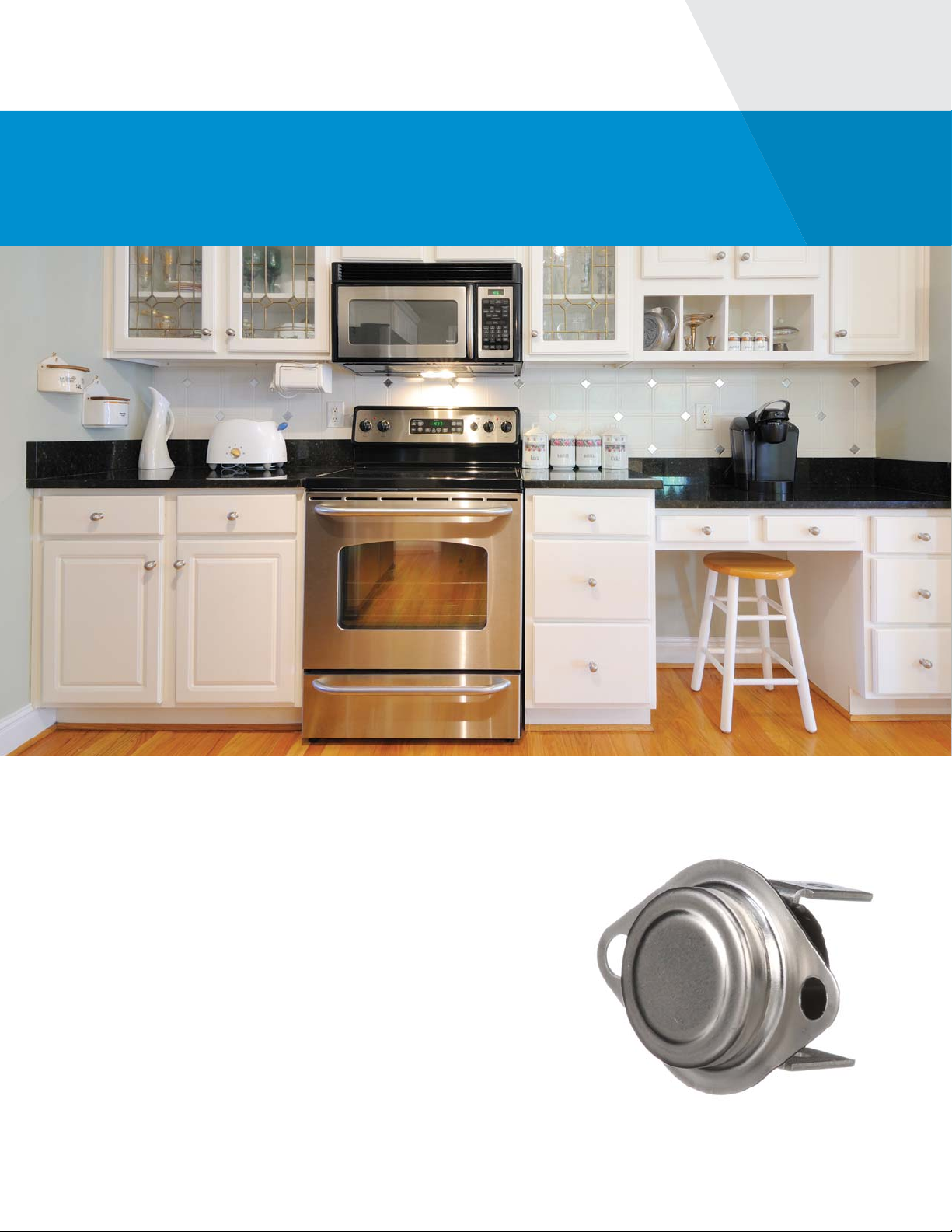
Bimetal Disc
Thermostat
Product Information and
Application Notes
Page 4

Table of Contents
Application Notes ...........................................................................................................................................3
10H /10HMR ................................................................................................................................................12
10RS .............................................................................................................................................................16
12S, 14S, 15S ...............................................................................................................................................19
14T ...............................................................................................................................................................26
30M ..............................................................................................................................................................33
36T /36TMR/36F ..........................................................................................................................................38
37T ...............................................................................................................................................................52
39T ...............................................................................................................................................................61
44T, 48T .......................................................................................................................................................65
49T, 49F .......................................................................................................................................................70
58T ...............................................................................................................................................................74
59T, 66T .......................................................................................................................................................79
60T/60TMR ..................................................................................................................................................85
60F, 61F ........................................................................................................................................................95
64T,64F ........................................................................................................................................................98
69T ............................................................................................................................................................ 102
74T ............................................................................................................................................................ 108
75TF .......................................................................................................................................................... 112
HLX ........................................................................................................................................................... 117
Page 5
Bimetal Disc Thermostat
Application Notes
Operating Principles
Bimetal disc thermostats are thermally actuated switches.
When the bimetal disc is exposed to its predetermined calibration
temperature, it snaps and either opens or closes a set of contacts.
This breaks or completes the electrical circuit that has been applied
to the thermostat.
Bimetal Disc Thermostat Therm-O-Disc3
Page 6
There are three basic types of thermostat switch actions:
• Automatic Reset: This type of control can be built to either open or close its electrical contacts as the temperature
increases. Once the temperature of the bimetal disc has returned to the specifi ed reset temperature, the contacts
will automatically return to their original state.
• Manual Reset: This type of control is available only with electrical contacts that open as the temperature increases. The contacts may be reset by manually pushing on the reset button after the control has cooled below the
open temperature calibration.
• Single Operation: This type of control is available only with electrical contacts that open as the temperature
increases. Once the electrical contacts have opened, they will not automatically reclose unless the ambient that
the disc senses drops to a temperature well below room temperature (typically below -31°F).
Temperature Sensing & Response
Many factors can affect how a thermostat senses and responds to temperature changes in an application.
Typical factors include, but are not limited to, the following:
• Mass of the thermostat
• Switch head ambient temperature. The “switch head” is the
plastic or ceramic body and terminal area of the thermostat.
It does not include the sensing area
• Air fl ow across the sensing surface or sensing area.
The “sensing surface” (or area) consists of the bimetal disc and metal
disc housing
• Air fl ow across the switch head of the thermostat
• Internal heating from carrying the application electrical load
• Disc cup or housing type (i.e. enclosed, as on left in picture below, or
exposed, as on right)
• Rate of temperature rise and fall in the application
• Intimacy of contact between the thermostat sensing surface and the surface it is mounted on
• Heat transfer by conduction, convection or radiation
Therm-O-Disc Bimetal Disc Thermostat4
Page 7
It is important to understand that the temperature of the thermostat will typically change more slowly than or lag the
temperature it is trying to sense. The impact of the factors mentioned previously will determine the magnitude of the
thermal lag. Thermal lag will directly affect determination of thermostat calibration to regulate or limit temperature
for a particular application. Reference the “Determining Calibration” section for how to use a thermocouple sample
thermostat to establish thermostat calibration.
Control Location
The location of the thermostat should be carefully selected. Adequate time should be used to determine the
temperatures in the various locations within the product to assure the location of the sensor can best measure
and control the performance of the product. Various methods may be employed to measure these temperatures
such as infrared thermography, multiple thermocouples, etc.
Determining Calibration
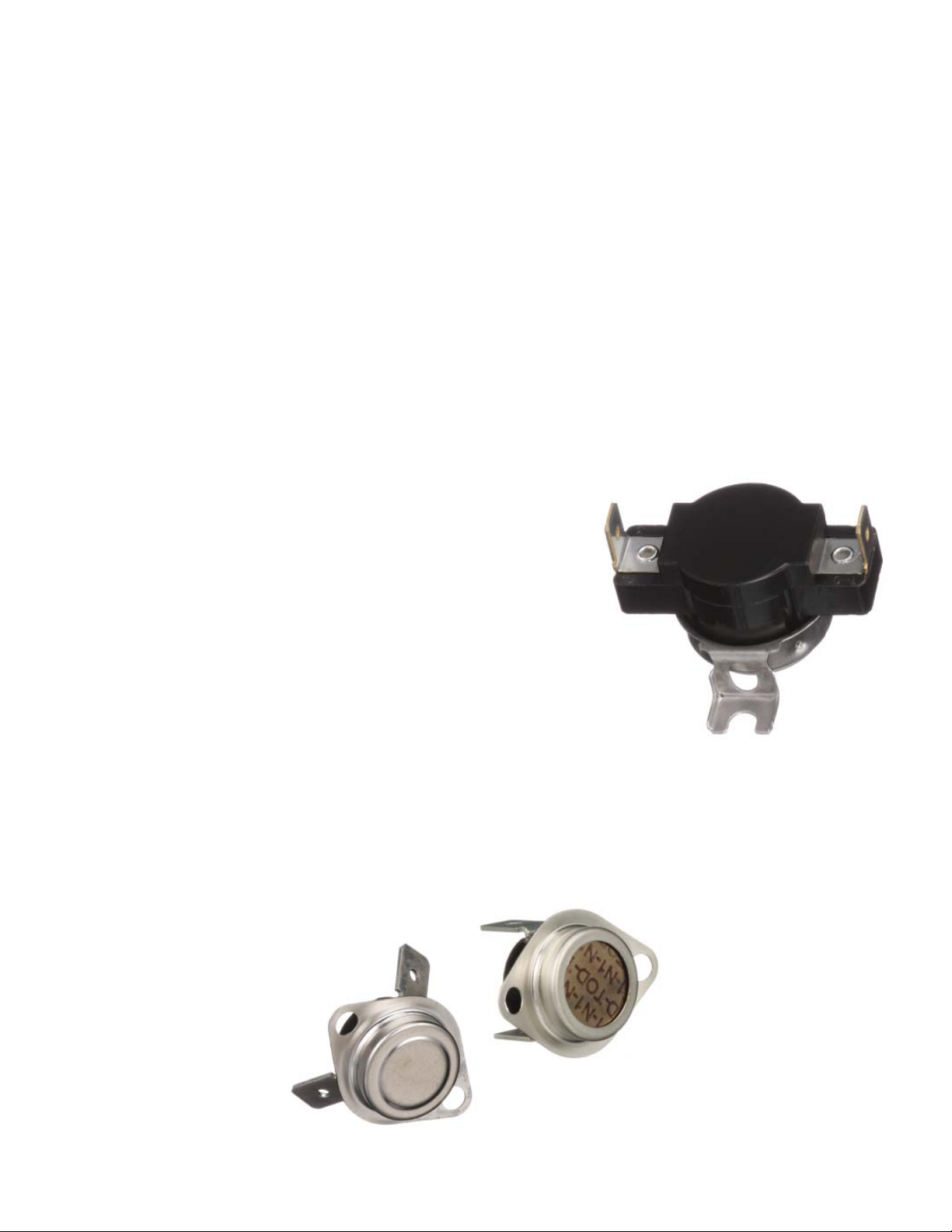
A thermocouple sample thermostat is typically used as a key indication of what the calibration temperature of a
thermostat should be for a particular application (see Figure 3). The thermocouple is ideally attached internally to the
control on the bimetal disc for optimum results since the bimetal disc is the component that senses the temperature in
a bimetal thermostat. The sample control has the same thermal response as a functional thermostat but the
contacts will not open.
Once a preliminary calibration temperature has been determined with the thermocouple sample control, a
functional control calibrated at the desired temperature must be tested in the application to verify that the calibration
is appropriate. Therm-O-Disc provides thermocouple samples upon request. Type J, Type K, and Type T
thermocouples are available.
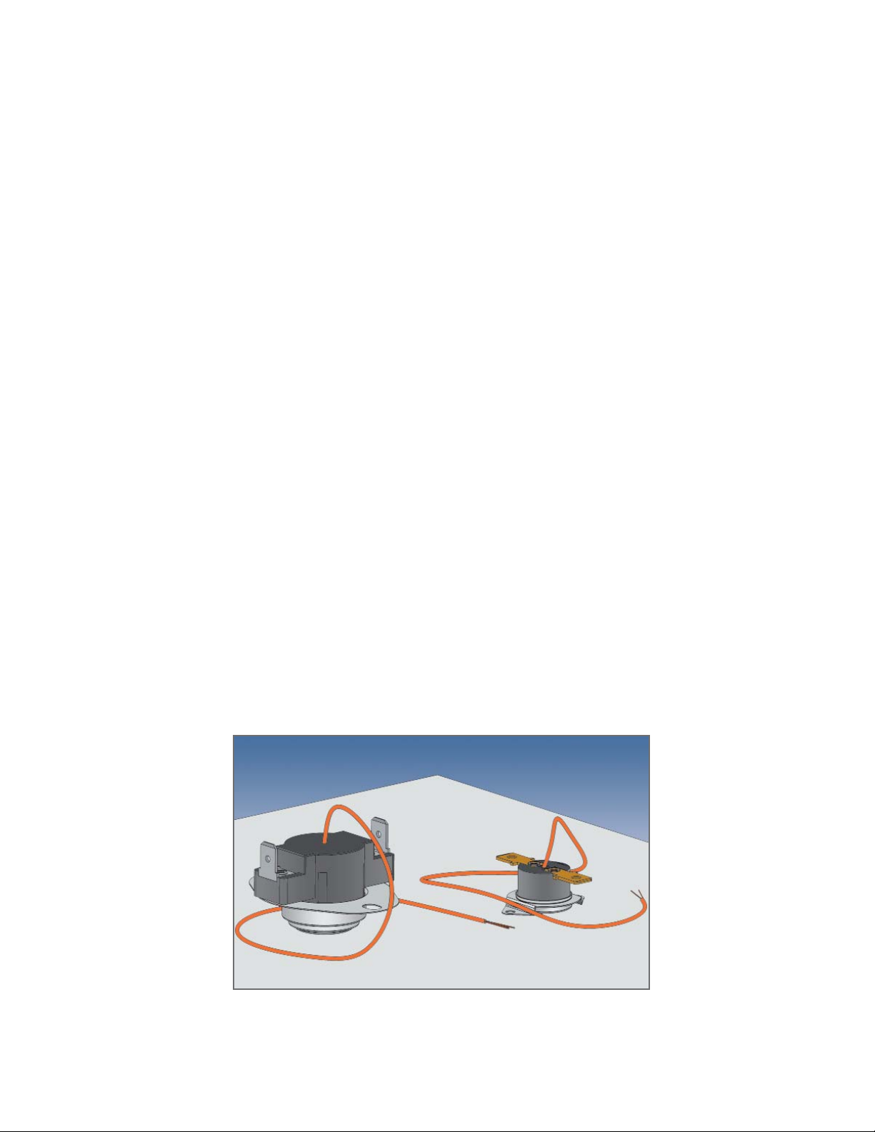
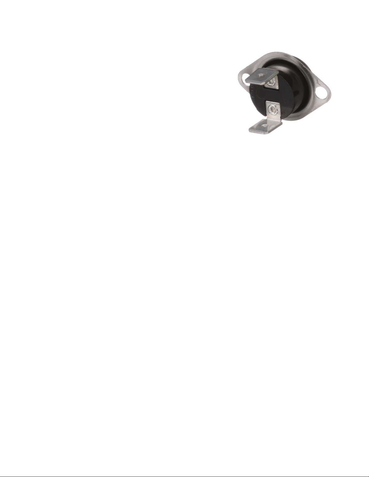
A thermocouple may be placed externally on a thermostat (see Figures 4 and 5). The preferable location would be on
the metal disc “cup” / mounting bracket at a point closest to the sensing surface. The sensing surface is the fl at area of
the “cup” or bimetal housing for thermostats with enclosed bimetal discs. Those with
exposed bimetal discs should have the thermocouple positioned as close to the disc as is practical. Care should be
taken to assure that the thermocouple wires do not contact one another except at the sensing junction.
Figure 3
Thermocouple Sample Controls
Bimetal Disc Thermostat Therm-O-Disc5
Page 8
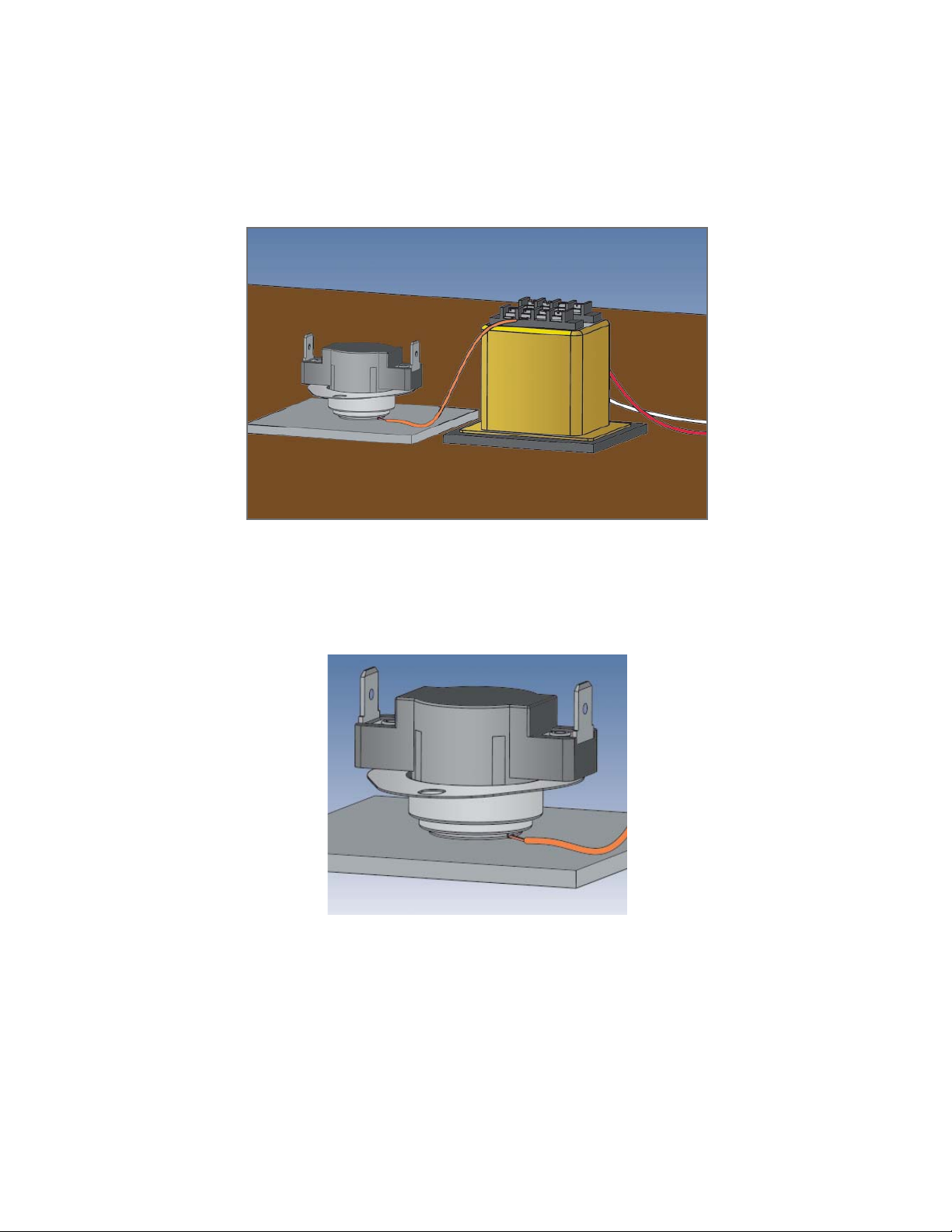
Figure 4
Thermocouple placed externally to thermostat
Figure 5
Thermocouple placed externally to thermostat
Therm-O-Disc Bimetal Disc Thermostat6
Page 9

Thermostats are used to both regulate and to limit temperatures.
A thermostat that regulates temperature is exposed to temperatures
of normal operating conditions of a particular application, plus an
overshoot temperature. A thermostat that limits temperature is exposed
to temperatures of abnormal operating conditions, plus an overshoot
temperature. It is important to determine both the normal and abnormal
operating temperatures as well as the respective temperature overshoots
in each application in order to specify the appropriate thermostat
calibration. Since most applications include both regulating and limiting
thermostats, it is essential to prevent nuisance tripping of the limit by
fully understanding the temperature overshoots. It is important to know
what the maximum exposure temperature is to assure that components
and complete units do not exceed their respective rated temperatures.
The maximum exposure temperature is the combined result of the maximum ambient temperature added to the
temperature increase due to the application plus the overshoot.
Test Guidelines
Install the thermocouple sample thermostat in the appropriate location (see earlier section named “Control Location”)
using both the same mounting and electrical connections as will be used in the application. The thermocouple lead
should be connected to a device that will monitor and record the output from the thermocouple. Only personnel
properly trained in the safe use of electrical equipment should perform testing. Caution must be exercised to assure
that line voltage, if present, must not injure personnel or damage equipment. Use of an isolation transformer is
recommended if there is any chance that the thermocouple wires may see line voltage.
CAUTION To avoid a false reading of the unit under test, thermocouple wires must not make contact with
each other except at the temperature sensing junction.
CAUTION Ensure that the thermocouple wire insulation will provide isolation against short circuiting and
shock hazards.
CAUTION The terminal of the temperature measuring instrument, to which the thermocouple is attached,
will be the same potential as the connecting circuit wire. This instrument must be
electrically isolated and considerable caution must be exercised in its use, since one of the
thermocouple terminals is frequently grounded to the instrument chassis.
It will likely be necessary to conduct several trials with varying ambient temperature, air fl ow rate and/or volume,
rate of temperature rise or fall, etc. to identify normal and abnormal operation. Normal manufacturing and
assembly variation between units and any applicable approval agency requirements or industry standards must
also be considered.
Bimetal Disc Thermostat Therm-O-Disc7
Page 10
Monitor the temperatures under normal operating conditions using the
thermocouple sample thermostat. Repeat using conditions for abnormal
operating conditions. Conduct as many trials as are necessary to understand
all the potential fault conditions and to assure that the rated temperature of
components (including the thermostat) and the test units are not exceeded.
The test may be set up to be able to manually open the electrical circuit
when the thermocouple sample thermostat reaches a particular target
temperature (as determined from testing described above). Continuing to
monitor the temperature of the thermocouple sample after the circuit is
manually opened, and determining the maximum temperature excursion
beyond the “open” temperature can determine the temperature overshoot.
This can be conducted for both regulating and limiting thermostats. Once the preliminary calibration value for the
thermostat has been determined, by taking into account normal and abnormal operating conditions, product and
test variation and overshoots, it is necessary to repeat testing with functional thermostats. It may be necessary to
try thermostats calibrated both higher and lower than the targeted temperature to better optimize the calibration
temperature. This will also provide useful information for specifying the calibration tolerance.
Important Notice
Users must determine the suitability of the control for their application, including the level of reliability required, and
are solely responsible for the function of the end-use product. These controls contain exposed electrical components
and are not intended to withstand exposure to water or other environmental contaminants which can compromise
insulating components. Such exposure may result in insulation breakdown and accompanying localized
electrical heating.
A control may remain permanently closed or open as a result of exposure to excessive mechanical, electrical, thermal
or environmental conditions or at normal end-of-life. If failure of the control to operate could result in personal injury
or property damage, the user should incorporate supplemental system control features to achieve the desired level of
reliability and safety. For example, backup controls have been incorporated in a number of applications for
this reason.
Therm-O-Disc Bimetal Disc Thermostat8
Page 11

Glossary
Ambient – The typical environmental temperature at which a product is exposed.
Approval Agencies – Agencies created to verify the safety and/or functionality of electrical and gas household
products. Therm-O-Disc products are typically recognized at the major global agencies, including UL, CSA, VDE,
CQC, and MITI.
Automatic Reset – A type of thermostat that will reset itself at a specific temperature (set point minus differential =
reset temperature).
Bimetal – Metallic strip material made by bonding two different materials together with different thermal
expansion rates.
Bumper – An actuating pin that transmits motion from the sensing mechanism to an actuating arm.
Contacts – Term for components used in all electrical-type products that physically make and break
electrical circuits.
Comparative Tracking Index (CTI) – A measure of material surface electrical tracking (resistance).
Cycle Rating – The agency-recognized number of operations that a control will function, given a specific temperature
range and electrical load.
Dielectric Strength – A product’s ability to withstand an application of a pre-determined over-voltage for a specified
period of time.
Differential – The temperature difference between the opening and closing points of a control.
Disc Cup – A cup that holds a disc in place on a disc-type control.
Disc – A thin, circular bimetallic component.
DPDT (Double Pole, Double Throw) – An electrical term where “pole” is a leg of an electrical circuit and “throw”
describes the switch action. Therefore, a DPDT will switch two legs and each leg will open a set of contacts, and close
another set (4 contacts).
DPST (Double Pole, Single Throw) – An electrical term where “pole” means a leg of an electrical circuit and “throw”
describes the switch action. Therefore, DPST will switch two legs and each leg is switched open or closed by one
mechanism.
Fan-Type Control – A thermal control designed such that the contacts close on temperature rise. Also referred to as
“close on rise,” or “normally open.”
Fuse-Type Control – A control built to cycle only once.
Limit-Type Control – A thermal control designed such that the contacts open on temperature rise. Also referred to as
“open on rise,” or “normally closed.”
M1 – Refers to manual reset devices. If the reset button is held down, the control can cycle thermally.
M2 – Refers to manual reset devices. If the reset button is held down, the control must stay open and not
reset automatically.
Bimetal Disc Thermostat Therm-O-Disc9
Page 12

Manual Reset (M.R.) – A control that opens automatically, but must be reclosed manually by pressing a button
or lever.
NTC (Negative Temperature Coefficient) – A resistor that reduces resistance (ohms) with a temperature increase.
Pole – The number of completely separate circuits contained in a control.
Prime Differential – The thermal differential between the nominal open temperature and the minimum close
temperature.
PTC (Positive Temperature Coefficient) – A resistor that increases resistance (ohms) with temperature increase.
Reference Dimension – A dimension without tolerance used only for information purposes that does not govern
production or inspection operations.
Reset Temperature – The temperature at which the contacts return to their normal position.
Set Point – Temperature at which normally closed contacts will open, or normally open contacts will close. Also
referred to as operating temperature.
SPDT (Single Pole, Double Throw) – An electrical switch term where “pole” means a leg of an electrical circuit and
“throw” describes the switch action. Therefore, a SPDT will switch one leg that will open a set of contacts, and close
another set.
SPST (Single Pole, Single Throw) – An electrical term describing switch actions. A SPST will switch one leg and open
one set of contacts.
Stenciling – The marking on a product identifying the product type, calibration temperature, part number and plant
of manufacture.
Switchcase – The component that represents the thermostat “body,” made from insulating material that supports
switch mechanisms.
Thermal Cutoff (TCO) – A product that functions as a thermal fuse (one time operation). Various operating
temperatures are achieved by formulating a pellet that melts at very specific temperatures.
Thermistor – A device that exhibits a large change in electrical resistance with a change in temperature.
Tolerance – The allowable range above or below the set point or reset temperature.
Trip-Free – A term associated with manual reset type controls. When the reset button is depressed it cannot restrict
the normal opening of the control.
Therm-O-Disc Bimetal Disc Thermostat10
Page 13

Important Information
Many variables can affect the operational characteristics of a thermostat. It is for this reason that we recommend
that you conduct thorough testing of our products in your specific application. Therm-O-Disc has both functional and
thermocoupled samples readily available for determining the desired performance and the correct response in your
application. To obtain samples please contact your local Therm-O-Disc sales representative directly. To ensure a quick
turnaround, please have the following information ready:
• Application description
• Electrical load
• Operating temperature requirements
• Agency recognition(s) required
• Mounting and terminal confi gurations
• Estimated annual volume
Don’t know what product you need? Do you have a general question about our products? Visit
thermodisc.com or contact your local Therm-O-Disc sales office. Our Applications Engineers are
always available to assist you in answering your questions or in obtaining any samples you may need.
Bimetal Disc Thermostat Therm-O-Disc11
Page 14

10H Linear Limit Series
Special Purpose Controls
Snap-Action Capillary Controls
The 10H series temperature control from Therm-O-Disc was originally developed to sense
hot spots along the length of electric baseboard heaters. It is also used in other applications
where it is necessary to sense temperatures along a continuous length.
The 10H capillary tube is vacuum-charged with selected fl uids to give specifi c calibrations.
When the calibration temperature is reached, a change in fl uid vapor pressure allows the
diaphragm to snap through and operate the contacts. The snap-action design provides
high-speed contact separation and excellent reliability.
Typical applications for the 10H include electric baseboard heaters and other HVAC
applications.
Therm-O-Disc Bimetal Disc Thermostat12
Page 15
Features and Benefits
The 10H features include:
• The ability to sense temperature along a continuous length.
• Excellent sensitivity. Since the capillary tube is charged, the 10H responds to the hottest spot along the capillary tube.
• High-speed contact separation for long contact life.
• Design flexibility provided by a variety of switch actions, capillary tube lengths, mounting brackets and terminations.
Switch Actions
The 10H is available in two switch actions:
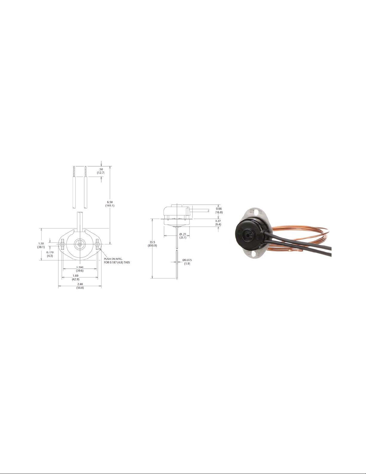
Automatic Reset (Type 10H11) – SPST contacts open on temperature rise and automatically reset on temperature fall
(see figure 1).
Shown with terminal cover and “push on” mounting bracket.
Figure 1
Dimensions are shown in inches and (millimeters).
Manual Reset (Type 10H14) – SPST contacts open on temperature rise and can be reset when the control has cooled to
a lower temperature and the reset button has been depressed. The 10H manual reset is agency recognized as an “M1
trip free” construction, which means that if the reset button is held down, the control can cycle thermally
(see figure 2).
Bimetal Disc Thermostat Therm-O-Disc13
Page 16
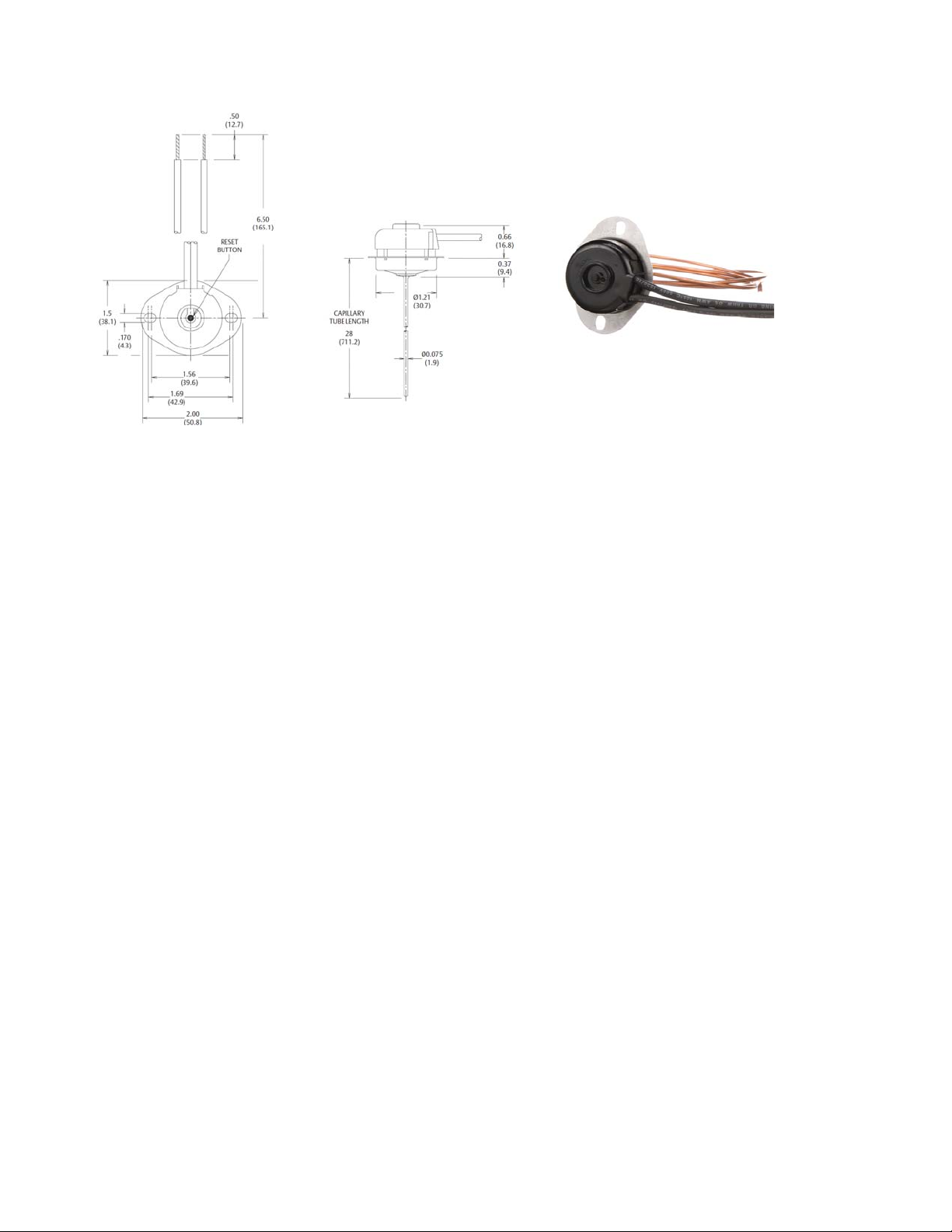
Shown with required terminal cover and standard mounting bracket
Figure 2
Dimensions are shown in inches and (millimeters).
Terminal Characteristics
The 10H can be calibrated to open on temperature rise between 150°F (65.6°C) and 350°F (177°C), with a standard
tolerance of ±15°F (±8.5°C). The 10H automatic reset will reclose the contacts at approximately 40°F (22°C) below its
open temperature. Manual reset controls may automatically reset when exposed to temperatures below -31°F (-35°C).
Capillary Tube
The 10H is available with the copper capillary tube in preferred lengths from 24” to 144” as measured from the bottom
of the mounting fl ange.
Mounting Brackets
The standard mounting bracket (see fi gure 2) has two slots, each .170” (4.318mm) wide. An alternate “push on”
mounting bracket (see fi gure 1) is also available.
Terminations
Standard leads are two 6 1/2” (165.1mm), #14 AWG, 105°C, 1/32” (10.8mm) thick, black PVC insulation, stripped 1/2”
(12.7mm). Also available (automatic reset only) are 1/4”(6.30mm), 90° angle, .032” (0.8mm) blade terminals. A
snap-on terminal cover is available for controls supplied with lead wires.
Therm-O-Disc Bimetal Disc Thermostat14
Page 17

General Electrical Ratings
The 10H series of controls has been rated UL and CSA. The agency ratings can be used as a guide when evaluating
specifi c applications. However, the mechanical, electrical, thermal and environmental conditions to which a control
may be exposed in an application may differ signifi cantly from agency test conditions. Therefore, the user must not rely
solely on agency ratings, but must perform adequate testing of the product to confi rm that the control
selected will operate as intended in the user’s application.
Thermostat
Typ e
10H11
(Auto Reset)
10H14
(Manual
Reset)
10H11
(Auto Reset)
10H14
(Manual
Reset)
Note: For complete and current ratings, please consult a Therm-O-Disc sales engineer. At thermostat end-of-life, the contacts may remain
permanently open or closed.
Maximum Open
Temperature
350 °F (177 °C) 221 °F (100 °C)
350 °F (177 °C) 221 °F (100 °C)
350 °F (177 °C) 221 °F (100 °C)
350 °F (177 °C) 221 °F (100 °C)
Maximum
Switchcase
Temperature
Volts ACResistive
277
600
277
600
277
600
277
350
600
Amperes
25
25
25
10
25
15
10
-
-
Inductive Amps
FLA LRA
4.8
4.8
28.8
-
-
-
-
-
28.8
-
-
-
Pilot
Duty VA
480
125
480
125
125
-
460
350
400
Cycles
100,000
100,000
6,000
6,000
100,000
100,000
6,000
6,000
6,000
Agency
Recognition
Guide MBPR2,
File MH-5304
CSA File
LR19988
UL
Bimetal Disc Thermostat Therm-O-Disc15
Page 18

10RS Radiant Energy Series
Special Purpose Control
Snap-Action Radiant Controls
The 10RS line of controls from Therm-O-Disc offers reliable sensing of radiant energy
in hot surface ignition applications, such as gas clothes dryers.
The unique snap-action bimetal design not only provides high-speed contact
separation and time-proven reliability, but also enables the 10RS to maintain radiant
sensitivity while compensating for ambient temperature changes.
A glass ‘window’ is used to maximize the effect of radiant energy on the bimetal
element without exposing the entire control to high ignitor temperatures.
These features have made the Therm-O-Disc 10RS an integral component of gas
ignition systems.
Therm-O-Disc Bimetal Disc Thermostat16
Page 19
Features and Benefits
The 10RS features include:
• Glass “window” design maximizes effect of radiant energy without sensor overheating.
• Unique “U”-shaped actuator compensates for ambient temperature conditions.
• High-speed contact switching for exceptional life characteristics.
Switch Actions and Typical Applications
The 10RS is an automatic reset, single pole, single throw (SPST) switch that opens its electrical contacts when exposed
to heat generated by radiant energy. This is accomplished with a “U”-shaped bimetal actuator which has one leg
exposed to radiant energy while the other leg is shielded.
As radiant energy passing through the glass “window” heats the exposed bimetal leg, a temperature differential is
created which causes the bimetal element to snap and open the contacts. As radiant energy dissipates, both actuator
legs return to approximately the same temperature, allowing the contacts to automatically reclose.
Typical Applications
The type 10RS control is utilized in gas-fired appliances in conjunction with a hot surface ignitor. As red hot ignitor
temperatures are achieved, the 10RS opens the circuit which signals the gas valve to open. Upon ignition, radiant
energy from the gas flame keeps the 10RS open until the operating cycle is completed. Once the gas valve closes and
the flame dissipates, the contacts reclose and the ignition cycle is complete.
Calibration
The standard 10RS calibration calls for the contacts to open within 12 to 20 seconds after exposure to a radiant energy
source. Contact reclose occurs within 26 to 40 seconds after the radiant source dissipates.
Note: Calibration timing of the 10RS in the actual application is dependent upon the type of ignition system and
position of the sensor relative to the radiant energy source.
Dimensions are shown in inches and (millimeters).
Bimetal Disc Thermostat Therm-O-Disc17
Page 20
Mounting Bracket
The 10RS is available in two standard tab mounts. The brackets are fabricated from .032”
(.81mm) aluminum and can easily be mounted with a sheet metal screw.
Terminal Configurations
The 10RS is furnished with .032” x .250” (.81mm x 6.35mm) brass quick connects in the
horizontal position.
General Electrical Ratings
The agency ratings can be used as a guide when evaluating specifi c applications. However,
the mechanical, electrical, thermal and environmental conditions to which a control may be
exposed in an application may differ signifi cantly from agency test conditions. Therefore, the user must not rely solely
on agency ratings, but must perform adequate testing of the product to confi rm that the control selected will operate
as intended in the user’s application.
Maximum Bimetal
Temperature (°F)
375 325 100,000 5.75 120
Note: At thermostat end-of-life the contacts may remain permanently closed or open. For complete and current ratings, please contact our Sales
Engineering Department
Maximum Ambient
Temperature (°F)
Cycles Resistive Amperes Volts AC Agency Recognition
CSA
File 112672-0-000
Therm-O-Disc Bimetal Disc Thermostat18
Page 21

12S, 14S, 15S Series
Time Delay Relays and Sequencers
Time Delay Relays and Sequencers
The Therm-O-Disc type 12S, 14S and 15S series time delay relays and sequencers are fi eld-
proven devices for controlling the operation of heating elements and/or fans in electric
furnaces and heat pumps. These controls combine a solid-state positive temperature
coeffi cient (PTC) heater with bimetal actuated contacts to provide time-delayed electrical
switching. A wide variety of bimetal disc and PTC combinations are available to provide a
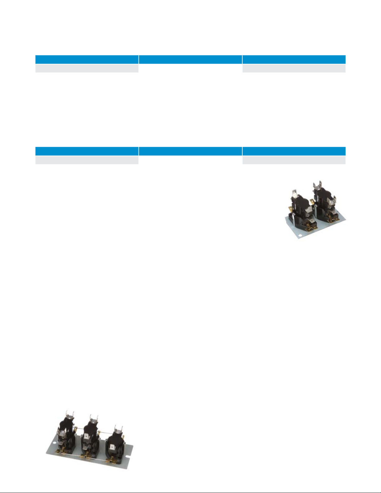
broad range of timings. The 12S is a single timing device while the 14S uses two bimetal discs
to achieve two independent timings. The 15S consists of one, two or three 12S and/or 14S
controls mounted on a common plate.
Bimetal Disc Thermostat Therm-O-Disc19
Page 22
Features and Benefits
The 12S, 14S and 15S features include:
• Available with auto-reset SPST, DPST and SPDT switch configurations.
• PTC heater for stable operation over a wide range of temperatures and voltages.
• Snap-action bimetal disc for high-speed contact separation.
• Standard operating ambients between -40°F (-40°C) and 150°F (65.6°C).
• Available with a wide variety of terminals and mounting plates.
• Welded construction for integrity of current-carrying components.
• Quiet operation
Switch Actions and Typical Applications
Automatic Reset SPST – Can be built to either open or close a set of contacts within a specified time range.
Automatic Reset DPST – Utilizes one bimetal disc to simultaneously open or close two independent sets of contacts
within a specified time range.
Automatic Reset SPDT – This 12S configuration is the same as the SPST except with the addition of an auxiliary
contact that makes and breaks circuit in opposition to the main contacts.
CAUTION . . . When designing a SPDT circuit, an electrical load must be applied to terminal 2 and/or 3 to avoid a
transient short circuit condition during switching.
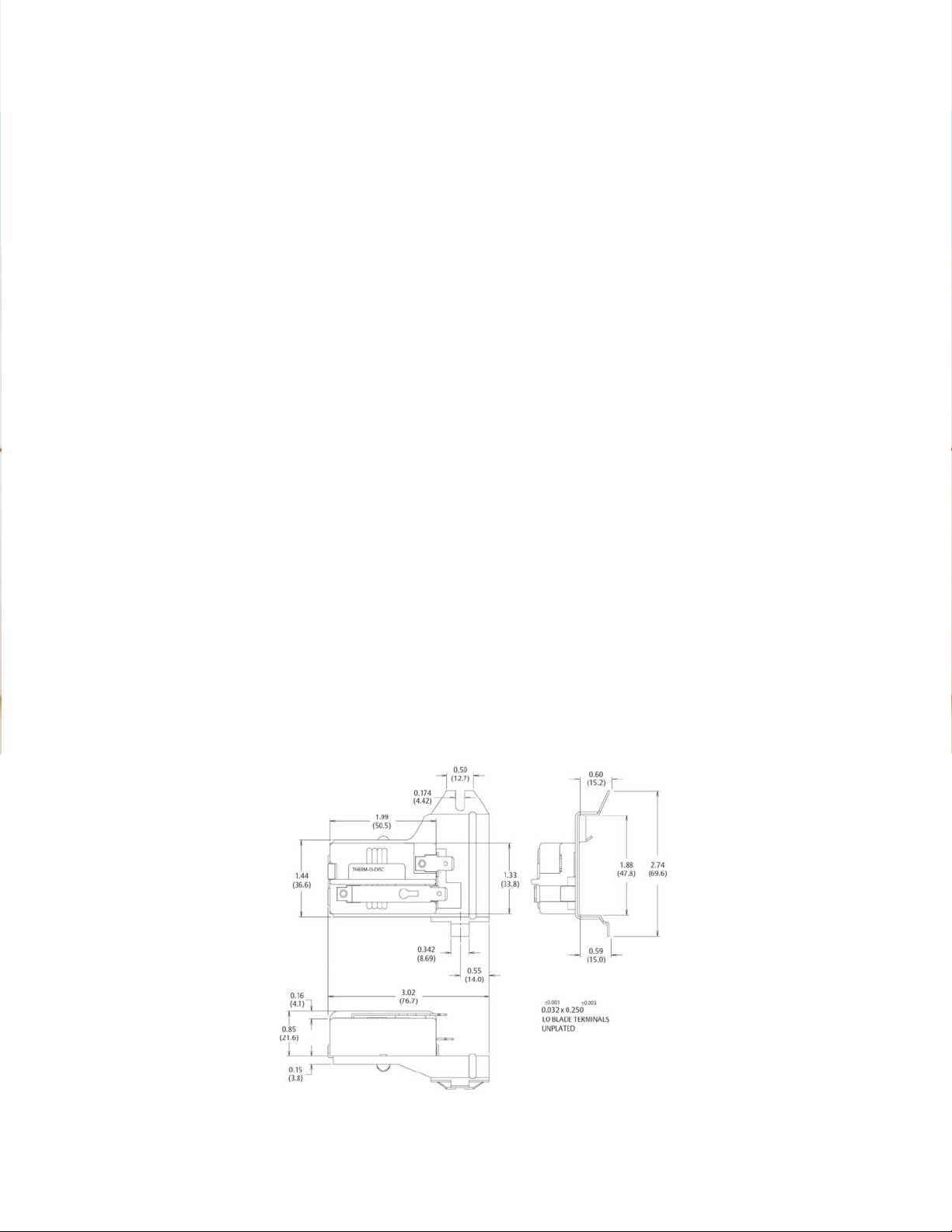
12S Series
The 12S series utilizes one bimetal disc to achieve single-timing operation. The 12S is available in SPST (see figure 1),
SPDT (see figure 2), and DPST (see figure 3) switch actions. A variety of standard timings are available for general time
delay applications.
SPST Switch Action
(12S20)
SPDT Switch Action
(12S50)
Figure 1
Therm-O-Disc Bimetal Disc Thermostat20
Figure 2
Page 23
12S Timings*
PTC ON OFF
24VAC
*Please contact us to discuss specific timings needed.
DPST Switch Action
(12S22)
Figure 3
Dimensions are shown in inches
and (millimeters).
1-30 Sec. 40-80 Sec.
10-40 Sec. 20-60 Sec.
20-55 Sec. 15-55 Sec.
25-110 Sec. 5-45 Sec.
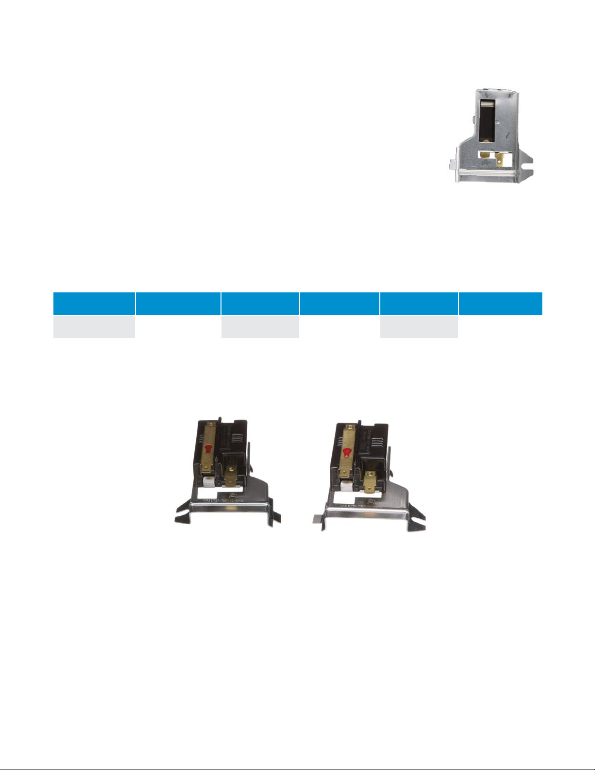
14S Series
The 14S series is available in two possible configurations:
• 2 stages, where each stage is SPST and operated by a disc for each stage. The two stages can
have different on/off times. See figure 4.
• 3 stages, where the two lower stages are DPST operated simulataneously by one disc. The
top stage is SPST and operated by the other disc.
SPST Switch Action (Each Stage)
(14S22)
Figure 4
Dimensions are shown in inches and (millimeters).
Bimetal Disc Thermostat Therm-O-Disc21
Page 24
14S Timings*
PTC ON OFF
24VAC 1-110 Sec. 1-110 Sec.
*Please contact us to discuss specific timings needed.
15S Series
The 15S series consists of either two or three 12S and /or 14S controls mounted on a common baseplate. The timing of
the package assures that a set of designated contacts will turn on fi rst and turn off last.
The chart shows the timing range for the 15S package.
15S Timings*
PTC ON OFF
24V 1-110 Sec. 1-110 Sec.
*Please contact us to discuss specific timings needed.
PTC Heater
Solid state PTC (Positive Temperature Coeffi cient) heaters are used to bias the operation of the
contacts. These heaters are self-current limiting for stable switch operation over a range of
temperatures and over-voltages. The standard line of controls uses a 24VAC PTC rated for Class
II circuits. The peak inrush current of the 24VAC PTC heater varies from .35 to 1.0 amps. The
inrush current drops below 1/2 of the peak value within approximately 10 seconds and reaches
a steady state current between 0.10 and 0.18 amps.
Operating Ambients
The standard sequencer line is designed to operate in ambients ranging from -40°F to 150°F (-40°C to 65.6°F). The
actual sequencer ON and OFF times are 100% checked to the required timings at a 75°F (23.9°C) ambient. The OFF
timings are determined after the PTC heater has been energized for a total of five minutes. Timings in an ambient
above or below 75°F (23.9°C) will vary and should be evaluated in the end use application to determine suitability. A
specfic high ambient construction is available at extra cost to allow operation up to 165°F (74°C). This construction
requires an “H” in our type number (example 12SH22).
Standard Terminals and Markings
The standard heater terminals are .032” x .250” (6.3 x .8mm) double 15° brass male quick connects. The stage
terminals are .032 x .250” (6.3 x .8 mm) tin plated brass. See figures 1, 2, 3, 4 for common stage terminals and
terminal numbering
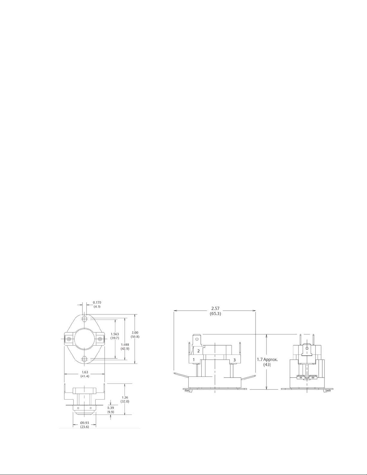
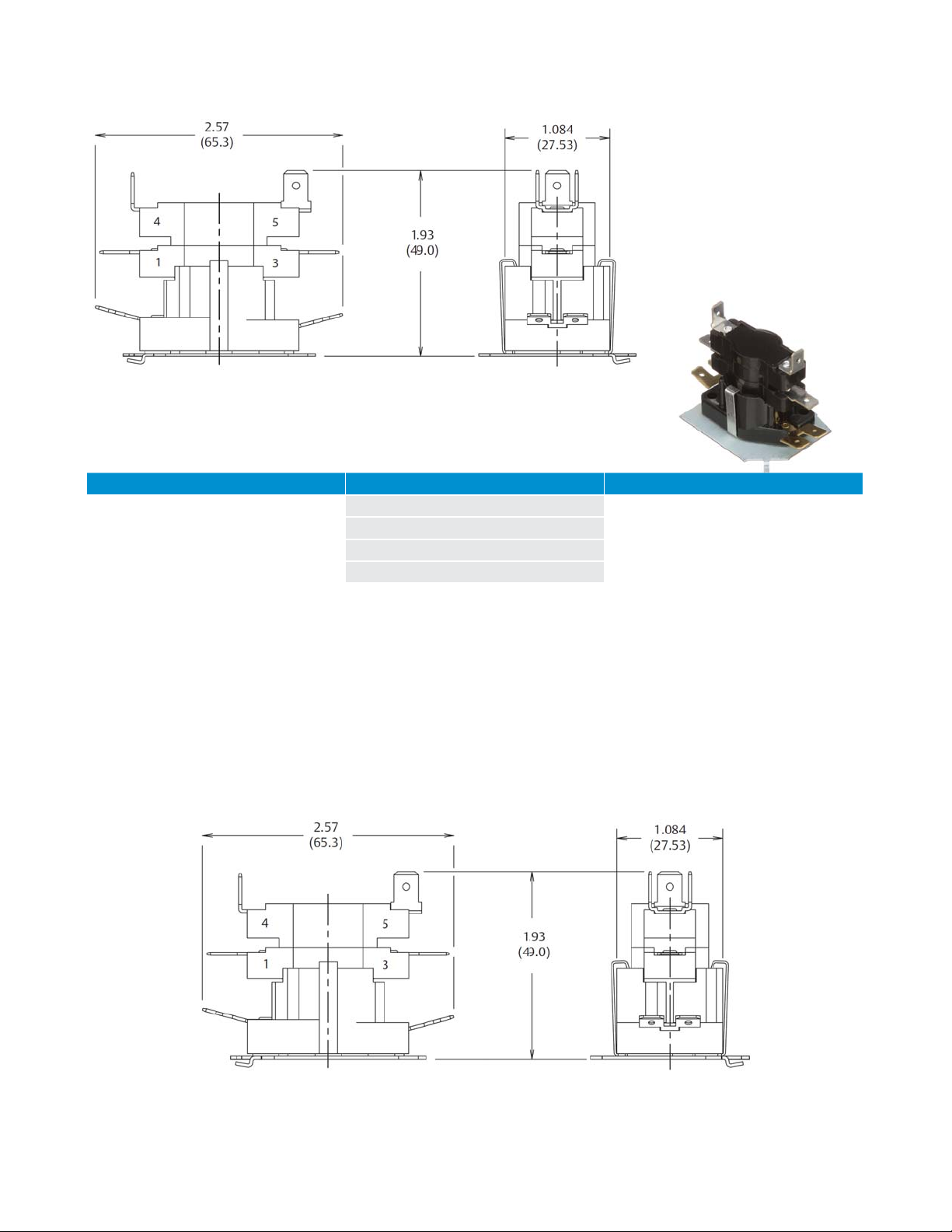
Mounting Plates
The standard mounting plate incorporates a tab and hole arrangement for mounting one (see figure 5) or two (see
figure 6) controls. The standard mounting plate for three controls incorporates a slot and hole arrangement (see figure
7). Optional or custom mounting plates are available to meet specific application requirements.
Therm-O-Disc Bimetal Disc Thermostat22
Page 25
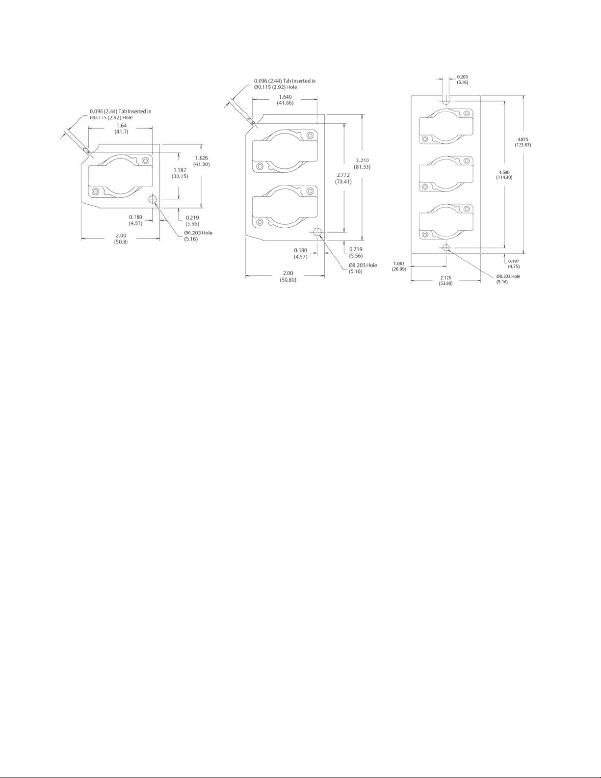
Figure 5
Figure 6
Figure 7
Electrical Spacings
The 12S, 14S, 15S series have electrical spacings of 1/4” (6.35mm) through air and 3/8” (9.52mm) over surface to
ground. With the suffix “X,” increased spacings of 3/8” (9.53mm) through air and 1/2” (12.7mm) over surface to
ground are available.
General Electrical Ratings
The agency ratings can be used as a guide when evaluating specific applications. However, the mechanical, electrical,
thermal and environmental conditions to which a control may be exposed in an application may differ significantly
from agency test conditions. Therefore, the user must not rely solely on agency ratings, but must perform adequate
testing of the product to confirm that the control selected will operate as intended in the user’s application.
Bimetal Disc Thermostat Therm-O-Disc23
Page 26

UL Agency Rating
Type Switching Action Volts AC
240 25 8 48 - 100,000
12S/15S SPST
12S
12S
12S/15S DPST
14S
* Note: For complete ratings information, please contact our Sales Engineering Department. At thermostat end-of-life, the contacts may remain
permanently closed or open. Maximum combination inductive/resistive, where maximum inductive load is 7FLA, 42LRA. Upper Stage Only.
(Auxiliary Contacts 1-2)
SPDT
(Main Contacts 1-3)
SPDT
2 Pole and
3 Pole
240 30* - - - 100,000
277 25 - - - 30,000
480 12.5 5 30 480 100,000
240 25 8 48 - 100,000
277 25 - - - 30,000
480 12.5 5 30 480 100,000
240 - 4.1 8 125 30,000
277 25 - - - 30,000
480 - - - 125 30,000
480 - 3 16 - 100,000
120 - 13.8 82.8 125 30,000
240 25 8 48 125 100,000
240 30* - - - 30,000
277 25 - - - 30,000
480 12.5 5 30 480 100,000
240 25 8 - - 100,000
240 30* - - - 100,000
480 12.5 5 - - 100,000
Resistive
Amps
Inductive amps
FLA LRA
Pilot Duty
VA
Cycles Agency Recognition
UL E19279
CSA Agency Ratings
Type Switching Action Volts AC
120 - 1.0 6.0 - 100,000
12S/15S SPST
12S
12S
12S/15S DPST
14S
* Note: For complete ratings information, please contact our Sales Engineering Department. At thermostat end-of-life, the contacts may remain
permanently closed or open. Maximum combination inductive/resistive, where maximum inductive load is 7FLA, 42LRA. Upper Stage Only.
(Auxiliary Contacts 1-2)
SPDT
(Main Contacts 1-3)
SPDT
2 Pole+
3 Pole
240 - 5.0 30 - 100,000
240 30* - - - 100,000
480 - - - 125 100,000
120 - 10 60 - 100,000
240 - 5 30 - 100,000
480 - - - 125 100,000
120 10 - - 125 100,000
240 5 5 30 - 100,000
480 - - - 125 30,000
120 - 10 60 - 100,000
240 25 5 30 - 100,000
240 30* - - - 100,000
480 - - - 125 100,000
240 25 5 30 - 100,000
240 30* - - - 100,000
480 - - - 12.5 100,000
Resistive
amps
Inductive amps
FLA LRA
Pilot Duty
VA
Cycles Agency Recognition
CSA 062037
Therm-O-Disc Bimetal Disc Thermostat24
Page 27

Part Numbering System
Common Sequencer Type Numbers for 12S and 145
Type Number of Stages Description
12S20 1 Normally Open, SPST
12S22 2 Normally Open, DPST
12S50 1 Normally Open, SPDT
14S22 2 Normally Open, Each Stage SPST
14S222 3 Normally Open –
Lower Two Stages DPST
Upper Stage SPST
15S Type Numbers
1st Suffi x
1st sequencer
on baseplate
2nd Suffi x
2nd sequencer on
baseplate (if provided)
3rd Suffi x
3rd sequencer on
baseplate (if provided)
1 1 1 12S20
2 2 2 12S22
4 4 4 14S22
You can combine any above confi gurations on a common base plate.
Example: 15S221 would contain 12S22-12S22-12S20
Base sequencer type
at each location
Bimetal Disc Thermostat Therm-O-Disc25
Page 28
14T Series
Moisture Resistant Temperature Controls
Heavy-Duty Snap-Action Temperature Controls
The 14T line of heavy-duty sealed bimetal disc controls from Therm-O-Disc meets the higher
electrical requirements of commercial applications. The design provides moisture resistance for
moisture prone environments. The snap-action of the 1” temperature sensing bimetal disc provides
high-speed contact separation resulting in exceptional life characteristics at electrical loads up to
25 amps at 120/240VAC. A variety of mounting confi gurations, lead wires and terminations
give maximum design fl exibility. The heavy-duty construction and long life characteristics
have made the 14T a popular choice for heating, ventilation and air conditioning systems.
Therm-O-Disc Bimetal Disc Thermostat26
Page 29

Features and Benefits
The 14T features include:
• Sealed construction provides moisture resistance for moisture prone environments.
• High-speed contact separation ensures long contact life.
• A wide variety of mounting configurations, lead wires and terminations provide maximum design flexibility.
• Large 25 amp capacity allows direct control of compressors and fans, reducing the need for additional components.
Switch Actions and Typical Applications
The 14T is available in two switch actions:
Automatic Reset SPST – In this configuration, the switch can be built to either open or close its electrical contacts
on temperature rise. Once the temperature in the application has returned to the specified reset temperature,
the contacts will automatically return to their original state. Typical uses of this construction include limiting and
regulating temperatures in air conditioners, heat pumps and fan coil units.
Automatic Reset SPDT – This design is the same as the SPST described above with the addition of an auxiliary contact
which makes circuit upon opening of the main contacts and breaks circuit when the main contacts reset. Refer to
the “General Electrical Ratings” chart for rating limitations on the auxiliary contacts. Typical uses of this construction
include fan speed changeover at a specified temperature and lighting of an indicator lamp when an abnormal
temperature condition has been reached.
Bimetal Disc Thermostat Therm-O-Disc27
Page 30
Mounting Configurations
The 14T is available in a variety of mounting configurations:
Surface Mounting – The surface mounting configuration positions the bimetal disc sensing element firmly against the
mounting surface, thereby sensing the actual mounting surface temperature (see figures 1 and 2).
SPST Surface Mounting
Figure 1
Dimensions are shown in inches and (millimeters).
SPDT Surface Mounting
Figure 2
Dimensions are shown in inches and (millimeters).
Therm-O-Disc Bimetal Disc Thermostat28
Page 31

No Mounting Flange – The 14T is available without a mounting flange for customers who wish to design their own
mounting method. Dimensions as shown in figures 1 and 2, except there is no mounting bracket shown.
Tube Mounting – In this mounting configuration, the 14T is supplied with a saddle-shaped disc cup and a removable
spring clip which holds the control firmly on a tube. This configuration is available for 3/8”, 1/2”, 5/8” O.D. tubes
figure 3).
(see
Figure 3
Dimensions are shown in inches and (millimeters).
Lead Wire and Terminal Configurations
The standard lead wires are #18 AWG stranded copper wire with 1/32” thick 105°C PVC insulation. A variety of other
lead wire size and insulation thickness combinations are available at additional cost. The standard lead wire direction
exits from the top of the control. The lead wire can also be specifi ed to exit perpendicular to the mounting hole center-
line for surface mount and parallel to the tube for tube mounting. This can be varied in 45 angular degree increments,
if required by the application.
Bimetal Disc Thermostat Therm-O-Disc29
Page 32

Conduit Connector – The 14T is also available with a conduit connector designed to enclose the lead wires in a rigid
thin wall or flexible metal conduit. In this configuration, the leads extend from the top of the control instead of the side
(see figure 4).
Figure 4
Dimensions are shown in inches and (millimeters).
The standard insulation colors are red, brown and black. Other colors can be provided, as required by a specifi c
application.
The standard maximum combined lead wire length is 24” for SPST and 36” for SPDT controls. Additional lead wire and
a variety of popular quick connect terminals are available at additional cost.
For more information on optional lead wires, insulation colors and terminations, please consult one of our sales
engineers.
Therm-O-Disc Bimetal Disc Thermostat30
Page 33

Calibration Temperatures, Differentials and Tolerances
To use the calibration chart, locate the range in the left hand column, in which the highest calibration set point (open
or close) falls. Then locate, across the top, the range in which the nominal differential falls. The standard open and
close set point tolerances are shown where the two columns converge. The chart also indicates which differentials are
available in each of the calibration set point ranges. Tighter open and close tolerances are available at additional cost.
For more information on tightened tolerances or availability of differentials not listed in the chart, please consult one of
oursales engineers.
Calibration Temperatures, Differentials and
Standard Tolerance of the 14T Series (SPST and SPDT only)
Highesy
Calibration Set
point Range
(Open or Close)
0°-80°F
-18°-26°C
81°-2221°F
27°-105°C
10-14°F
5.5-8°C
Open Close Open Close Open Close Open Close Open Close
±6
±3.5
±5
±3
Part Numbering System
14T
(Optional suffi x)
C - Conduit connector
±6
±3.5
±5
±3
Nominal Differentials
(nominal open and close set point)
15-19 °F
8.5-10.5 °C
±6
±3.5
±5
±3
±6
±3.5
±5
±3
20-29 °F
11-16 °C
±6
±3.5
±5
±3
1 - No mounting fl ange
2 - Surface mounting fl ange
3 - Tube mount
±6
±3.5
±5
±3
30-39 °F
16.5-21.5 °C
±6
±3.5
±5
±3
±7
±4
±5
±3
40-50 °F
22-33°C
±6
±3.5
±5
±3
1 - Contacts open on
temperature rise (SPST)
2 - Contacts close on
temperature rise (SPST)
3 - Single pole, double
throw (SPDT)
±7
±4
±7
±4
Bimetal Disc Thermostat Therm-O-Disc31
Page 34

General Electrical Ratings
The 14T series of controls has been rated by major agencies throughout the world. The agency ratings can be used as a
guide when evaluating specifi c applications. However, the mechanical, electrical, thermal and environmental condi-
tions to which a control may be exposed in an application may differ signifi cantly from agency test conditions. There-
fore, the user must not rely solely on agency ratings, but must perform adequate testing of the product to confi rm that
the control selected will operate as intended in the user’s application.
Max Temp. Contact Arrangement
SPST or SPDT any load
14T, 14F
221 °F*
105 °C
14T, 14F
150 °F*
65.5°C
265°F
129.5 °C
14T
221 °F*
105 °C
150 °F
65.5 °C
265 °F
129.9 °C
combination execpt
resistive rating on one
contact set only
SPST or SPDT any
combination
SPST or SPDT any load
combination execpt
resistive rating on one
contact set only
SPST or SPDT (125VA pilot
duty only on contacts 1-2
of SPDT)
SPST
SPST
SPDT
(limited to 125VA on one
contac t)
SPST or SPDT
(any load combination)
SPST
Cycles
Rating
6,000 16 72 125 - 120
6,000 10 45 125 - 240
30,000 10 60 125 25 120
30,000 5 30 125 25 240
30,000 16 72 125 15 240
30,000 10 60 125 - 277
100,000 10 60 125 25 120
100,000 5 30 125 25 240
30,000 2.5 15 575
100,000 0.5 600
100,000 0 0 125 25 277
100,000 10 120
30,000 10 60 125 25 120
30,000 5 30 125 25 240
60,000 16 72 125 - 120
60,000 10 45 125 - 240
30,000
30,000
30,000 7.5 45 125 15 120
30,000 3.75 22.5 125 15 240
30,000 16 72 125 - 240
30,000 2.5 15 575
100,000 0.5 600
100,000 10 120
Inductive Amps
FLA LRA
10
5
60
30
Pilot
Duty VA
125
125
Resistive
Amperes
5 240
25
25
5 240
Volts AC
120
240
Agency
Recognition
UL
E29653
CSA
LR10281
Note: This is a consolidated summary of the 14T series rating. For complete and current ratings information, please contact our Sales Engineering
Department. At thermostat end-of-life, the contacts may remain permanently closed or open.
Therm-O-Disc Bimetal Disc Thermostat32
Page 35

30M MOTOR PROTECTION Series
s
Special Purpose Controls
Special Purpose Controls
The Therm-O-Disc line of Motor Protectors offers accurate and reliable protection against hazardous
overheating in single phase/single voltage A/C motors. Available in a variety of product types,
these motor protectors employ a snap-acting, current and temperature responsive bimetal disc
for proven performance over life. An internal resistance heater utilizes the effects of current to
bias the operation of the bimetal disc for added thermal response. A wide range of bimetal
and heater combinations are available to cover specifi c design requirements. This design
fl exibility and proven performance has made Therm-O-Disc Motor Protectors a popular
choice among the leading manufacturers of fractional horsepower motors.
Bimetal Disc Thermostat Therm-O-Disc33
dou
Page 36

Features and Benefits
The Motor Protector features include:
• High-speed contact separation ensures long contact life.
• Current and temperature responsiveness for excellent design flexibility.
• Manual and automatic reset switching actions combined with a wide selection of bimetal discs
and heaters to meet a variety of possible application needs.
• 100% temperature calibration and trip time tests assure high quality levels.
The Operating Principle of Motor Protectors
The operating mechanism inherent to all Therm-O-Disc Motor Protectors is the snap-action bimetal disc. During
abnormal conditions, heat generated by resistance and/or motor ambient causes the bimetal disc to snap at the
specified calibration temperature. This allows the circuit to open within the maximum safe limits of the motor
windings. Once the motor returns to a normal operating temperature, the bimetal disc resets (automatically or
manually). This closes the circuit and re-energizes the motor. This same snap-action principle is utilized in millions of
Therm-O-Disc products applied in the appliance, heating and air conditioning industries.
Side Entry Terminals
Figure 1
Dimensions are shown in inches and (millimeters).
Therm-O-Disc Bimetal Disc Thermostat34
Page 37

End Entry Terminals
Figure 2
Dimensions are shown in inches and (millimeters).
Type 30M – The Therm-O-Disc Type 30M (see figure 4) SPST manual reset protector is a compact device designed for
applications where inadvertent equipment restarts may result in potential hazard. The contacts may be manually reset
after the control has cooled 30°-50°C below the open temperature calibration. The 30M features a “trip free” manual
reset design. UL designates the 30M reset as “M1,” meaning the motor protector shall automatically reset to the
closed position after normal operating conditions have been restored if the reset button is held in the reset position.
Typical uses include disposer and oil burner applications where “tripping” the device should result in the end user
taking corrective action. Standard terminations are weld-type connections. Male quick connect terminals, lead
wire assemblies and bimetal and heater combinations are available to meet specific requirements. This “trip free”
construction means that processing the reset button will not reclose the contacts until the control has cooled.
Figure 3
Dimensions are shown in inches and (millimeters).
Bimetal Disc Thermostat Therm-O-Disc35
Page 38

Lead Wire and Terminal Configurations
All Therm-O-Disc Motor Protectors can be furnished with a variety of terminal and lead wire confi gurations. Custom
packages or special assemblies may be specifi ed to meet unique application needs. By taking advantage of our high
volume production methods, Therm-O-Disc may be able to provide signifi cant savings. Our sales engineers can assist
in selecting a package that is tailored to specifi c requirements.
Mounting Configurations
Due to the variation of terminal and switch configurations, Therm-O-Disc Motor Protectors may be mounted in
a number of positions. For maximum performance, we recommend locating the protector as close to the motor
windings as possible. Customers typically provide their own mounting methods.
Product Quality
Therm-O-Disc Motor Protectors are assembled, calibrated and tested automatically, using the latest manufacturing
technologies and quality methods. Each motor protector is 100% temperature calibrated and tested to ensure high
quality levels. Our goal of providing motor protectors of the highest uniform quality is reinforced by the training of
our operators in modern statistical techniques. Therm-O-Disc is committed to continuously improving our quality
and manufacturing capabilities. This objective, in turn, allows our products to meet the escalating standards of our
customers.
Protector Selection
To determine which Therm-O-Disc Motor Protector is right for a specifi c application, simply use the following steps:
• Select the appropriate switch action (manual or automatic) and product type.
• Verify that electrical load does not exceed the recommended rating of the device.
• Determine calibration based on test data.
• Determine the specifi c bimetal and heater resistance required for the application. (Consult factory for trip curves.)
• Test the protector to verify compliance with specifi c requirements.
• Choose from a variety of optional components to complete a package.
Calibration Range, Differentials, and Standard Tolerances
Protector Type 30M
Open Range (°C) 80-150
Open Tolerance (°C) ±5
Close Range (°C) 45-110
Close Tolerance (°C) ±10
Minimum Differential (°C) 30
Maximum Differential (°C) 50
NOTE: For additional information on calibrations, tolerances or differentials not listed in this chart, please contact our Sales Engineering Department.
Therm-O-Disc Bimetal Disc Thermostat36
Page 39

General Electrical Ratings
The Motor Protector series has been rated by major agencies throughout the world. The agency ratings can be used
as a guide when evaluating specifi c applications. However, the mechanical, electrical, thermal and environmental
conditions to which a control may be exposed in an application may differ signifi cantly from agency test conditions.
Therefore, the user must not rely solely on agency ratings, but must perform adequate testing of the product to
confi rm that the control selected will operate as intended in the user’s application.
Protector
Typ e
30M 150
* Therm-O-Disc Motor Protectors are recognized by Underwriters Laboratory (UL) and certifi ed by the Canadian Standards Association
(CSA). For complete details on European Agencies or the latest rating information, please contact our Sales Engineering Department.
Maximum
Temperature (°C)
Recommended
Contact Ratings*
50 amp L.R. @ 120 V
37 amp L.R. @240V
Limited
Short Circuit
1000 amp Circuit:
40 amp fuse @240V
Group Fusing
Short Circuit
2000 amp Circuit:
80 amp fuse @120V
Recognition
File E52937
File LR80616
Part Numbering System
30M
Bimetal Resistance
A- .0015 Ω
B- .0042 Ω
L- .0075 Ω
Heater Resistance
A- .0320 Ω
B- .0260 Ω
C- .0390 Ω
D- .0620 Ω
E- .0490 Ω
G- .0980 Ω
L- .0200 Ω
M- .0150 Ω
Terminal Type
No. 1 No. 3
5- Stub 1/4” MQC
6- Stub Stub
Open (°C)
A- 86
B- 90
C- 95
D- 100
E- 105
F- 110
G- 115
H- 120
J- 125
K- 130
L- 135
M- 140
N- 145
P- 150
S- 80
Close (°C)
A- 45
B- 50
C- 55
D- 60
E- 65
F- 70
G- 75
H- 80
J- 85
K- 90
L- 95
M- 100
N- 105
P- 110
Agency
UL
CSA
Bimetal Disc Thermostat Therm-O-Disc37
Page 40

36T Series
Snap-Action Temperature Controls
Snap-Action Temperature Control
The 36T Series of 1/2” bimetal temperature controls from Therm-O-Disc offers
proven reliability in a compact, versatile, cost-effective design. The snap
action of the bimetal disc provides high-speed contact separation resulting
in excellent life cycle characteristics at electrical loads up to 15 amps at
120VAC and 10 amps at 250VAC (100,000 cycles) and 16 amps at 250VAC
(30,000 cycles).
A variety of terminal and mounting configurations are available for maximum
design flexibility. The quality, reliability, affordability, versatility and world-wide
agency approvals of the 36T Series make it the thermostat of choice for a wide
variety of temperature control applications.
Therm-O-Disc Bimetal Disc Thermostat38
Page 41

Switch Actions
The 36T is available in three single pole, single throw (SPST) switch actions:
Automatic Reset – Can be built to either open or close its contacts on temperature rise.
Manual Reset – Available with contacts that open on temperature rise. The contacts can be reset by depressing the
button after the control has cooled down.
Single Operation Fuse Disc – Available with contacts that open on temperature rise, and which never reclose unless
the ambient temperature drops below +32°F (0°C) or below -31°F (-35°C).
Typical Applications
The 36T is applied to a wide variety of applications as either a regulating control or a safety limit. Examples of
applications include:
• Coffeemakers • Water heaters
• Sandwich toasters • Furnaces
• Dishwashers • Boilers
• Dryers • Electric heaters
• Washing machines • Offi ce equipment
• Refrigerators • Automotive seat heaters
• Microwave ovens
Mounting Confi gurations
The 36T is available in several mounting configurations:
No Mounting Bracket – The 36T may be specified without a mounting bracket. One popular version (designated
36TM or 36TMH) has a switch body designed to accept the customer’s clamp bracket (see Figure 1).
1.32
(33.5)
Ø0.62
(15.8)
0.26
(6.7)
0.57
(14.4)
0.48
(12.1)
Ref.
0.09
(2.4)
Figure 1
Dimensions are shown in inches and (millimeters).
Bimetal Disc Thermostat Therm-O-Disc39
Page 42

Surface Mount Bracket – The bimetal disc sensing element is positioned firmly against the mounting surface so it
senses the actual mounting surface temperature (see Figure 2). There are many available surface mounting brackets
available – typically in either aluminum or stainless steel.
0.145
(Ø3.70)
2 Holes
1.23
(31.2)
0.94
(23.8)
0.29
(7.4)
1.32
(33.6)
0.47
(11.9)
0.01
0.69
(17.6)
(0.4)
Figure 2
Dimensions are shown in inches and (millimeters).
Surface brackets can be supplied on the 36T either loose or crimped in a fixed position (except for ceramic body 36Ts,
36Ts with stainless steel disc housings, and 36Ts with raised pad disc housings, which must be supplied loose).
Airstream Mount – The bimetal housing extends through a hole in the mounting surface into the airstream (see
Figure 3). There are many available aluminum and stainless steel airstream mount configurations.
Ø0.145
(3.70)
Mounting
Holes
1.18
0.94
(30.0)
(23.8)
0.81
(20.6)
0.63
(16.0)
0.83
(21.1)
Ø0.62
(15.8)
0.18
(4.6)
Figure 3
Dimensions are shown in inches and (millimeters).
Therm-O-Disc Bimetal Disc Thermostat40
Page 43

Terminal to Mounting Hole Crimp Angle
Both surface brackets and air stream housings can be supplied where the customer can specify the angular
orientation (in 15 degree increments) of the terminals with respect to the mounting hole centerline (see figure 4).
45°
90°
90° crimp angle 45° counterclockwise crimp angle
Figure 4
Stud Mount – The 36T can be supplied with an integral threaded stud mount. Figure 5 shows two popular brass stud
mounts with hex shape (brass stud available with plastic switchcases only). Figure 6 shows an aluminum stud mount
available with plastic or ceramic switchcases.
Figure 5
Figure 6
Bimetal Disc Thermostat Therm-O-Disc41
Page 44

36T Board Mount – The 36T is mounted on extension straps, for applications where the thermostat must extend
further into the airstream to sense adequately (see Figure 7). Available strap lengths include 2” (50.4mm), 3”
(75.6mm), 5” (126mm) and 7” (176.4mm). Insulating sleeves can be provided for the extension straps, and various
mounting board configurations are available.
Figure 7
Thermal Response
Most 36Ts are provided with an enclosed disc. The enclosed disc construction provides greater protection against
airborne contaminants entering the control. It also protects the bimetal disc from possible damage during customer
handling. In applications where faster response to radiant heat is required, an exposed bimetal disc can be specified.
36T Mounting Options
The letter “A” means available. Consult a Sales Engineer for other available configurations.
Surface Mount – No Mounting Bracket
Description Aluminum
Enclosed (raised pad) A A Figure 8
Enclosed (fl at) A A Figure 9A
Exposed A A Figure 9B
Ø0.62
(15.8)
(not available with ceramic body)
Ø0.62
(15.8)
Stainless Steel
Ø0.62
(15.8)
Drawing
Figure 8 Figure 9A
Dimensions are shown in inches and (millimeters).
Therm-O-Disc Bimetal Disc Thermostat42
Ø0.47
(11.9)
Figure 9B
Page 45

Surface Mount – With Mounting Bracket
Mounting Hole Aluminum Bracket Stainless Steel Bracket Drawing
0.125” (3.2mm) diameter
0.145” (3.7mm) diameter
0.172” (4.4mm) diameter
1.14
(28.9)
0.94
(23.8)
Figure 10A Figure 10B Figure 11
Airstream Mount
Mounting Hole
A
A
A
A
__ A
Ø0.125
(Ø3.2)
2 Holes
1.14
(28.9)
0.94
(23.8)
Ø0.145
(Ø3.7)
2 Holes
Dimensions are shown in inches and (millimeters).
Aluminum
(enclosed)
Aluminum
(exposed)
Stainless Steel
(enclosed)
(not avaiilable with ceramic body)
1.75
(44.4)
1.18
(30.2)
1.31
(33.4)
Stainless Steel
(exposed)
Figure 10A
Figure 10B
Figure 11
0.172
(4.40)
Drawing
0.145” (3.7mm) diameter A A A A Figure 12
0.188” (4.74mm) wide slot A A A A Figure 13
0.170” (4.28mm) wide slot
0.21
(5.2)
0.19
(4.8)
0.94
(23.8)
1.18
(30.0)
Figure 12
Enclosed Disc
Exposed Disc
0.145
(Ø3.7)
__ A
0.21
(5.2)
0.19
(4.8)
0.188
(4.74))
1.70
(43.1)
1.25
(31.8)
Figure 13
A A Figure 14
0.21
(5.2)
Enclosed Disc
Exposed Disc
0.94
(23.8)
0.18
(4.5)
0.170
(4.28)
2.00
(50.8)
1.56
(39.7)
1.69
(42.9)
Figure 14
Enclosed Disc
Exposed Disc
1.50
(38.1)
Dimensions are shown in inches and (millimeters).
Bimetal Disc Thermostat Therm-O-Disc43
Page 46

Stud Mount
Thread Stud length Material Drawing
M4 x 0.7mm 0.24” (6mm)
M4 x 0.7mm 0.190” (4.7mm) Aluminum Figure 16
36T Terminals
(not available with ceramic body)
0.24
[6.0]
M4 X 0.7 mm
0.62
[15.9]
Brass
0.19
[4.7]
Figure 15
Dimensions are shown in inches and (millimeters).
ÿ
0.62
[15.8]
Figure 16
Figure 15
M4 X 0.7 mm
Most 36Ts are supplied with 1/4” x .032” (6.3mm x .8mm) quick connect blade terminals that are available in
unplated brass, tin plated brass and nickel plated steel. We also have 3/16” (4.8mm) blade terminals available in both
.020” (0.5mm) and .032” (0.8mm) thicknesses. Most of these blade terminals are available in 0, 45 and 90 degree
angles. The 36T can also be supplied with various weld tab and crimp/solder terminals. Please see the 36T
Standard Terminals chart that shows our most frequently used terminals. Note that other configurations/platings
may be available if our standard offerings do not satisfy your application. Please contact a Sales Engineer to
discuss requirements.
Therm-O-Disc Bimetal Disc Thermostat44
Page 47

36T Standard Terminals
Dimensions are shown in inches and (millimeters). “A” designates available.
Mounting Hole Terminal Angle
3/16 x .020 (4.8 x 0.5 blade)
3/16 x .032 (4.8 x 0.8 blade)
1/4 x .032 (6.3 x 0.8 blade without stops)
1/4 x .032 (6.3 x 0.8 blade)
.020 (0.5) weld tab 90
.020 (0.5) crimp/solder 90
.020 (0.5) solder low -- A -- Figure 23
.020 (0.5) PCB solder 90
low
45
90
low
45
90
low
45
90
low
45
90
O
O
O
O
O
O
O
O
O
O
O
Unplated
Brass
A
-A
A
A
A
A
A
A
-A
A
-- -- A Figure 21
-- A -- Figure 22
-- A -- Figure 24
Tin Plated
Brass
A
A
A
A
A
A
A
A
A
A
A
A
Tin Plated
Brass Steel
A
A
A
A
-A
A
A
A
A
-A
Drawing
Figure 17
Figure 18
Figure 19
Figure 20
3/16 (4.8) x 0.020 (.5) Blade
90
Available
Angles
45
Low
3/16 (4.8) x 0.032 (.8) Blade
90
45
Low
Available
Angles
1/4 (6.3) x 0.032 (.8) Blade Without Stops
90
45
Low
Available
Angles
Figure 17 Figure 18 Figure 19
1/4 (6.3) x 0.032 (.8) Blade
90
45
0.020 (.5) Weld Tab
Low
Available
Angles
Figure 20 Figure 21
0.020 (.5) Crimp / Solder
18 - 20 Ga. Wire
0.020 (.5) Solder
0.11
(Ø2.8)
0.020 (.5) PCB Solder
Figure 22 Figure 23 Figure 24
Dimensions are shown in inches and (millimeters).
Bimetal Disc Thermostat Therm-O-Disc45
Page 48

36T Switchcases
There are many available switchcases (or switchbodies) available for the 36T. When choosing a particular switchcase,
there are several key items to consider:
Electrical Spacing – This is the minimum distance required to prevent electrical “arcing” from a live part (terminal)
to a dead part (disc housing). The required electrical spacing is determined by the customer’s agency spacing
requirements. There are 36T switchcases with two different spacings available:
• 1/8” (3.2mm) by 1/4” (6.3mm) air/surface – designated by an ‘X’ in the nomenclature (see Figure 25). (Preferred)
• 1/16” (1.6mm) by 1/16” (1.6mm) air/surface (see Figures 26, 27).
The greater spacings are achieved by an increased switchcase height.
Mounting – All of the available switchcases can be provided in both surface (with or without brackets) or airstream
mount configurations. There are several switchcases designed to accept a customer clamp bracket (over the top of
the switchcase). These are designated by an ‘M’ in the nomenclature. (See Figure 27)
0.58
(14.6)
0.58
(14.7)
0.47
(11.9)
0.58
(14.7)
0.37
(9.5)
0.26
(6.7)
0.47
(12.1)
0.57
(14.4)
1/8 (3.2) X 1/4 (6.3) Spacing
TX, TXE, TXH
Figure 25
1/16 (1.6) X 1/16 (1.6) Spacing
T, TE, TH
Figure 26
Dimensions are shown in inches and (millimeters).
1/16 (1.6) X 1/16 (1.6) Spacing
TM, TMH, TME
Figure 27
Switchcase Material – For calibrations up to 350°F (177°C), plastic can be specified; for calibrations above 350°F
(177°C), ceramic is available. Ceramic switchcases are designated by ‘H’ in the nomenclature.
Manual Reset – Manual reset switchcases are basically similar to those used on automatic reset and fuse disc
configurations except for a hole in the top of the case (for the reset pin) and a pad on the top of the case to prevent
overtravel of the reset pin. Please refer to the manual reset portion of the catalog for more information.
Therm-O-Disc Bimetal Disc Thermostat46
Page 49

Calibration Temperatures, Differentials and Tolerances
36Ts (automatic reset) are supplied to customer specified open and close calibration set points with a tolerance on
both set points.
Please refer to the chart below. To use this chart, start by finding the higher of your open/close calibration set points in
the far left hand column. Then look across the top (left to right) to locate your desired nominal differential. Differential
is the difference between your nominal open and close calibration set points. The available open and close set point
tolerances are shown where the two columns converge. Please note that this chart is applicable to either normally
closed contacts (contacts open on temperature rise) or normally open contacts (contacts close on temperature rise).
Example 1:
If you require a nominal open temperature of 250°F (121°C) and a nominal close temperature of 210°F (99°C), then
the nominal differential = 40°F (22°C), so the tolerance on the open temperature is ±7°F (±4°C), and the tolerance on
the close temperature is ±11°F (±6°C). (Refer to the yellow shaded area in the chart.)
Example 2:
If you require a nominal close temperature of 160°F (71°C) and a nominal open temperature of 140°F (60°C), then the
nominal differential = 20°F (11°C), so the tolerance on the open temperature is ± 5°F (±3°C), and the tolerance on the
close temperature is ±7°F (±4°C). (Refer to the gray shaded area in the chart.)
Calibration Temperatures, Differentials and
Standard Tolerance for the 36T Series
Highest
Calibration
Set Point
(Open or
(Close)
35°F-79°F
2°C-26°C
80°F-180°F
27°C-82°C
181°F-230°F
83°C-110°C
231°F-300°F
111°C-149°C
301°F-350°F
150°C-177°C
351°F-428°F
178°C-220°C
*F15-19
*C8.5-10.5
11-13.5
Open Close Open Close Open Close Open Close Open Close Open Close Open Close Open Close
±5
±3±6±3.5±5±3±6±3.5±5±3
±5
±3±6±3.5±5±3
±5
±7
±3
-
-
-
-
-
-
±5
±4
±3
-
-
-
-
-
-
-
-
-
-
-
-
(temperature difference between nominal open and close set point)
20-24
25-29
14-16
±7
±4
±7
±5
±4
±7
±4
-
-
±3.5
-
-
-
-
±7
±3
±4
±5
±3±8±4.5±5±3±8±4.5±6±3.5±9±5
±6
±9±5±6
-
-
-
-
NOTES: 1. We can supply tolerances that are tighter than those shown at extra cost. Please contact a Sales Engineer.
2. Wider tolerances required for conical contact constuction. Please contact a Sales Engineer.
3. Requires ceramic construction for temperatures above 350°F (177°C)
4. Lowest nominal open or close calibration is -6°F (-21°C).
NOMINAL DIFFERENTIAL
30-39
16.5-21.5
±5
±3±8±4.5±6±3.5±8±4.5±7±4±9±5
±5
±3±8±4.5±5±3±8±4.5±6±3.5
±10
±3.5
±5.5±7±4
-
-
-
-
-
-
-
-
-
-
-
-
40-49
22-27
-
-
-
-
±11±6±8
-
-±8±4.5
-
-
50-60
27.5-33.5
±10
±5.5±7±4
±7±4±11±6±8
±11±6±9±5±14
±4.5
±12
±6.5
-
-
-
-
61-80
34-44.5
-
-
±11±6±
±12
±4.5
±6.5
±10
±15
±5.5
±8.5
±16±9±23
±13
-
-
±8
81-100
45-55.5
-
-
9±5±13
±10
±14
±5.5
±11±6±17
±9.5
±12
±20
±6.5
±11
±18
±25
±10
±14
-
-
±7
±8
Bimetal Disc Thermostat Therm-O-Disc47
Page 50

36T Manual Reset
The 36T manual reset is available with normally closed contacts that open on temperature rise and is a non-trip free
design. The 36T manual reset is normally supplied so that it does not automatically reset unless the ambient
temperature drops below -31°F (-35°C).
Once the 36T manual reset has opened at its calibration temperature, the ambient temperature must drop before it
can be reset. To determine the manually resettable temperature for a specific open temperature – refer to the refer
to the graph in Figure 28. The manually resettable temperature is the temperature at which (or below which) the 36T
can be reset. To use this chart, first find the point on the vertical axis that designates the nominal open temperature
minus the tolerance. Then, move across to the curve and find the manually resettable temperature on the horizontal
axis. There are two lines shown: one without a compressible washer, and one with a compressible washer. The
compressible washer (located under the reset button) can be specified (at extra cost) when the customer desires a
higher manually resettable temperature.
Example:
For an open temp/tolerance of 210°F (99°C) ±10°F (±5.5°C), the manually resettable temperature is 100°F (38°C)
without the compressible washer, which means that the 36T can be reset when the temperature is at or below
100°F (38°C).
360 (182)
350 (177)
340 (171)
330 (166)
320 (160)
310 (154)
300 (149)
290 (143)
280 (138)
270 (132)
260 (127)
250 (121)
240 (116)
230 (110)
220 (104)
210 (99)
200 (93)
190 (88)
180 (82)
170 (77)
160 (71)
150 (66)
140 (60)
Minimum Open Temperature – °F (°C)
130 (54)
120 (49)
110 (43)
100 (38)
90 100 110 120 130 140 150 160 170 180 190 200 210 220 230 240 250 260 270 280 290 300 310 320 330 340
(32) (38) (43) (49) (54) (60) (66) (71) (77) (82) (88) (93) (99) (104) (110) (116) (121) (127)(132) (138) (143) (149) (154)(160) (166) (171)
Manually Resettable Temperature - °F (°C)
Figure 28
Therm-O-Disc Bimetal Disc Thermostat48
-31°F (-35°C) MAX. AUTO
-31°F (-35°C) MAX. AUTO
RESET
RESET
-31°F (-35°C) MAX AUTO
RESET W/C. Washer
-31°F (-35°C) MAX AUTO
RESET W/C. Washer
Page 51

For 36T manual reset calibrations/tolerances, see the table below. Please contact a Sales Engineer if non-standard
calibrations or tolerances are required.
Calibration Range Standard Calibartion Tolerance
°F °C °F °C
150-200 65-93 ±8 ±4.5
201-240 94-115 ±10 ±5.5
241-280 116-138 ±12 ±6.5
281-320 139-160 ±14 ±8
321-350 161-177 ±16 ±9
36T Manual Reset Mounting and Terminals – The 36T manual reset is available with all of the mounting and
terminal configurations that are available on the automatic reset 36T. Figures 29 and 30 show two very
common configurations.
Figure 29 Figure 30
Single Operation 36F
The 36F fuse thermostat is a single operation version of the 36T. Once the electrical contacts have opened, they will
not reclose unless the ambient temperature drops below +32°F (0°C), or below -31°F (-35°C).
The 36F is available with any of the terminals, mounting configurations or switchcases that are available on the 36T
automatic reset version.
The 36F is available with the same open temperature set points and tolerances as the 36T manual reset. Please refer
to the chart in the manual reset section. The customer should specify either a +32°F (0°C) or a -31°F (-35°C) maximum
automatic reset temperature for the 36F.
Bimetal Disc Thermostat Therm-O-Disc49
Page 52

General Electrical Ratings
The 36T series of controls has been rated by major agencies throughout the world. Agencies include UL, CSA, VDE,
CQC, MITI, and KETI. 36T series controls are rated up to 15Amps @ 120Volts, and 16Amps @ 240Volts. The agency
ratings can be used as a guide when evaluating specifi c applications. However, the mechanical, electrical, thermal
and environmental conditions to which a control may be exposed in an application may differ signifi cantly from
agency test conditions. Therefore, the user must not rely solely on agency ratings, but must perform adequate testing
of the product to confi rm that the control selected will operate as intended in the user’s application. Please consult a
Sales Engineer for rating information that covers your specifi c application.
Type Numbering System
The following table summarizes the type numbering system for the 36T. These designations represent the type numbers that are agency recognized.
36 ____ ____ ____ ____ ____ ____
T – Automatic Reset or Manual Reset
F – Single Operation (fuse disc)
M – Switchcase designed to accept customer clamp (see figure 1)
X – Switchcase with increased electrical spacing
1/8” (3mm) through air and 1/4” (6.3mm) over surface
V – Conical movable contact – silver
VG – Conical gold movable contact (with gold-plated stationary contact)
E – Eyelet construction (required for European agency approval)
H – Ceramic switchcase
0 – No mounting bracket
1 – Airstream mount
2 – Surface mount bracket
3 – Stud mount
4 – Large flange – airstream mount
1 – Contacts open on temperature rise
2 – Contacts close on temperature rise
4 – Fuse disc with automatic reset
temperature below -31°F (-35°C)
6 – Manual reset or fuse disc with automatic reset
temperature below 32°F (0°C)
Therm-O-Disc Bimetal Disc Thermostat50
Page 53

36T Board Mount Nomenclature
36 ____ ____ ____ ____ ____
T – Automatic Reset – plastic switchcase
TH – Automatic Reset – ceramic switchcase
TVH – Automatic Reset – ceramic switchcase – conical silver movable contact
0 – No mounting bracket
1 – Contacts open on temperature rise
2 – Contacts close on temperature rise
B – Board mount
2 – 2” strap length*
3 – 3” strap length*
5 – 5” strap length*
7 – 7” strap length*
* Approximate length
Important Notice
Users must determine the suitability of the control for their application, including the level of reliability required,
and are solely responsible for the function of the end-use product. These controls contain exposed electrical
components and are not intended to withstand exposure to water or other environmental contaminants which can
compromise insulating components. Such exposure may result in insulation breakdown and accompanying localized
electrical heating.
A control may remain permanently closed or open as a result of exposure to excessive mechanical, electrical, thermal
or environmental conditions or at normal end-of-life. If failure of the control to operate could result in personal injury
or property damage, the user should incorporate supplemental system control features to achieve the desired level of
reliability and safety. For example, backup controls have been incorporated in a number of applications for this reason.
Bimetal Disc Thermostat Therm-O-Disc51
Page 54

37T Series
Moisture Resistant Temperature Controls
Moisture Resistant Temperature Controls
The 37T series of 3/4” (19mm) bimetal disc temperature controls from Therm-O-Disc offers
proven reliability in a moisture resistant sealed design. The snap-action of the bimetal disc
provides high-speed contact separation resulting in excellent life cycle characteristics at
electrical loads up to 10 amps at 120VAC and 5 amps at 250VAC. The sealed design provides
moisture resistance for moisture prone environments. A wide variety of terminal, lead wire
and mounting confi gurations are available to provide maximum design fl exibility.
The 37T is the most popular and widely applied temperature control in refrigeration
applications such as defrost termination and ice cube maker control. It is also applied in a
range of heat pump and air conditioning applications.
Therm-O-Disc Bimetal Disc Thermostat52
Page 55

Features and Benefits
The 37T features include:
• Sealed construction provides moisture resistance for moisture prone environments.
• High-speed contact separation ensures long contact life.
• A wide variety of mounting configurations, lead wires and terminations provide maximum design flexibility.
• All materials have been selected to pass the refrigeration industry’s odor and taste tests.
• Controls are 100% operation checked and dielectric tested.
Switch Actions and Typical Applications
The 37T is available in two switch actions:
Automatic Reset SPST – In this design, the switch can be built to either open or close its electrical contacts on temperature rise. Once the temperature in the application has returned to the specified reset temperature, the contacts
automatically return to their original state. Open on rise contact design is typically used for refrigeration defrost termination and ice cube maker control. Type 37TF includes an internal resistor wired in parallel with the contacts which
serves as an aid to factory circuit testing where the contacts are open at room temperature.
Automatic Reset SPDT – This design is the same as the SPST with the addition of an auxiliary contact which makes a
circuit upon the opening of the main contacts and breaks the circuit when the main contacts reset. In this design, any
combination of electrical ratings shown in the rating table may be switched from one circuit to the other.
Bimetal Disc Thermostat Therm-O-Disc53
Page 56

Mounting Configurations
The 37T is available in several mounting configurations:
No Mounting Bracket – The 37T may be specified without a mounting bracket. The 37T (see figure 1) is available
with a polyethylene cap or a phenolic centerpost which may be used for a customer’s bracket. The phenolic centerpost may be customized to meet unique requirements. mount configurations. Airstream mounting is typically used in
applications where the temperature being sensed is contained within an enclosure such as an air duct or heater box.
An optional surface mount configuration is available for applications where the temperature being sensed is the actual
mounting surface. Exposed or enclosed bimetal disc mounting versions may be specified.
Ø1.12
(28.5)
Ø1.02
(25.9)
0.075
(1.91)
0.78
(19.8)
Ø0.188
(4.78)
Figure 1
Dimensions are shown in inches and (millimeters).
Surface Mounting – The surface mounting configuration (see figure 2) positions the sensing element firmly against
the surface to be monitored.
0.172
(4.37)
038
(9.7)
T-O-
1.560
(39.62)
1.690
(42.93)
2.03
(51.6)
Therm-O-Disc Bimetal Disc Thermostat54
Figure 2
Dimensions are shown in inches and (millimeters).
Page 57

Tube Mounting – Several different tube mountings are available (see figures 4-7). These brackets firmly attach the
37T to tubes ranging from 1/4” (6.4mm) to 7/8” (22.2mm) in diameter. Radius cups provide best thermal response are
available in stainless stell, tin plated copper, and Aluminum.
0.38
(9.7)
1.35
(34.3)
Ø1.12
(28.5)
0.96
(24.4)
(35.0)
Ø1.04
(26.4)
1.40 Approx.
Figure 3
Dimensions are shown in inches and (millimeters).
0.56
(14.2)
T-O
Ø1.12
(28.5)
D
Ø1.04
(26.4)
1.40 Approx.
(35.0)
0.96 Max.
(24.4)
Figure 4
Dimensions are shown in inches and (millimeters).
Bimetal Disc Thermostat Therm-O-Disc55
Page 58

Ø1.06
(26.9)
0.64
(16.3)
Ø1.02
(25.9)
1.0 Approx.
(25)
Figure 5
Dimensions are shown in inches and (millimeters).
Lead Wire and Terminal Configurations
Standard Lead Wire- The standard leads for the 37T controls are available in lengths between 3” (76.2mm) and 36”
(914.4mm) with #18 AWG, 16/30 standard copper wire and 1/32” (0.8mm) thick 105 °C PVC odorless insulation
stripped 1/2” (13mm).
In additon, #16 AWG wire can be supplied with 1/32 (0.8mm) or 1/16” (1.6mm) thick insulation. The maximum wire
size available is #14 AWG with 1/32” (0.8mm) insulation.
Terminals- A wide variety of terminals can be attached to the 37T lead wires in addition to strip and retain. Please consult a Therm-O-Disc sales engineer for further variations of terminals, wire lengths, and/or wire types.
Pin terminals- The 37TB construction provides pin terminals in place of lead wire coming from the thermostat (see
fi gure 8).
High Temperature 37TJ Construction
The 37TJ construction incorporates a stainless steel disc cup, as well as high temperature sealant and lead wires. The
37TJ, available in SPST construction only, may be calibrated up to 300°F (149°) with maximum ambient temperatures
up to 257°F (125°C).
Therm-O-Disc Bimetal Disc Thermostat56
Page 59

Figure 6
Dimensions are shown in inches and (millimeters).
Clip-in Mounting – Clip-in mounting brackets (see figure 3) hold the sensing element firmly against the surface where
the thickness of the surface is from .03” (0.8mm) to .06” (1.5mm).
Figure 7
Dimensions are shown in inches and (millimeters).
Bimetal Disc Thermostat Therm-O-Disc57
Page 60

Thermal Response
The temperature sensitive bimetal disc is located at the bottom of the disc cup adjacent to the surface to be
monitored. Aluminum, tin-plated copper and stainless steel cups are available for calibrations not exceeding 172°F
(78°C) and temperature overrides not exceeding 200°F (93°C). Stainless steel disc cups may also be used for higher
temperature applications.
Calibration Temperatures, Differentials and Tolerances
To use the calibration chart, locate the range in the left hand column, in which the highest calibration set point (open
or close) falls. Then locate, across the top, the range in which the nominal differential falls. The standard open and
close set point tolerances are shown where the two columns converge. The chart also indicates what differentials are
available in each of the calibration set point ranges. Closer tolerances and special differentials are available at extra
cost. Please consult a sales engineer for further information.
0.133
(3.38)
0.310
(7.87)
0.64
(16.3)
45
Ø1.120
(28.45)
Ø0.090
(2.29)
(Typ.)
1.55
(39.4)
0.71 Ref.
(18.0)
0.84 Ref
(21.3)
Ø0.69
(17.5)
Ø1.04
(26.4)
Figure 8
Dimensions are shown in inches and (millimeters).
Therm-O-Disc Bimetal Disc Thermostat58
Page 61

Calibration Temperatures, Differentials and Tolerances
To use the calibration chart, locate the range in the left hand column, in which the highest calibration set point
(open or close) falls. Then locate, across the top, the range in which the nominal differential falls. The standard open
and close set point tolerances are shown where the two columns converge. The chart also indicates what differentials are available in each of the calibration set point ranges. Closer tolerances and special differentials are available
at extra cost. Please consult a sales engineer for further information.
Calibration Temperatures, Differentials and
Standard Tolerance of the 37T Series
Highest
Calibration Set
Point Range
(Open or Close)
10 °-80 °F**
-12 °-27 °C
81 °-200 °F***
28 °-93 °C
201 °-221 °F***
94 °-105 °C
222 °-300 °F****
106 °-149 °C
(37TJ only)
* SPDT – Minimum differential is 15°F (8°C).
** The minimum bottom temperature is -10°F (-23°C).
*** Type 37T maximum ambient temperature for the polyethylene cap is 172°F (78°C).
**** Type 37TJ maximum ambient temperature for the epoxy and lead wires in 257°F (125°C).
10-14F*
5.5-8 °C
Open Close Open Close Open Close Open Close Open Close Open Close
±5
±3
±5
±3
-
-
-
-
±6
±3.5
±5
±3
-
-
-
-
(temperature difference between nominal open and close set point)
15-19 °F
8.5-10.5 °C
±5
±3
±5
±3
±5
±3
-
-
±6
±3.5
±5
±3
±6
±3.5
-
-
Nominal Differentials
20-29 °F
11-16 °C
±5
±3
±5
±3
±5
±3
±6
±3.5
±6
±3.5
±5
±3
±7
±4
±8
±4.5
30-39 °F
16.5-21.5 °C
±5
±3
±5
±3
±6
±3.5
±7
±4
Part Numbering System
37T
±7
±4
±7
±4
±8
±4.5
±9
±5
40-50 °F
22.27.5 °C
±5
±3
±5
±3
±7
±4
±8
±4.5
±7
±4
±7
±4
±8
±5
±11
±6
51-80 °F
28-44.5 °C
-
-
-
-
-
-
±9
±5
-
-
-
-
-
-
±13
±7
A- Increased inductive
load ratings
J- High temperature
construction
V- Low load resistive
applications, using
conical contacts
VG- Low load resistive
applications, using
gold conical contacts
B- Pin terminals
C- Conduit connector
E- Eyelet construction
(required for European
agency approval)
F- Internal resistor added
to facilitate OEM factory
continuity testing
G- Low load resistive and
inductive applications,
using gold contacts
Bimetal Disc Thermostat Therm-O-Disc59
0- No mounting bracket
2- Surface mounting bracket
3- Tube mounting
1- SPST, open on
temperature rise
2- SPST, close on
temperature rise
3- SPDT, with
auxiliary contact
Page 62

General Electric Rating
The 37T series of controls has been rated by major agencies throughout the world. The agency ratings can be used as a
guide when evaluating specific applications. However, the mechanical, electrical, thermal and environmental conditions to which a control may be exposed in an application may differ significantly from agency test conditions. Therefore, the user must not rely solely on agency ratings, but must perform adequate testing of the product to confirm that
the control
selected will operate as intended in the user’s application.
Thermostat
Typ e
37T, 37TB,
37TJ
37TV, 37TVF
37TG,37TVG
37TA
37TF *** SPST only 100,000 5.8 34.8 125 10.0 1200 120
37TJ
37T, 37TJ
37TJ
37TG
37TVG
37TA
37TV, 37TVF
37TF *** SPST only 100,000 5.8 34.8 125 10.0 1200 120
37TE
37TFE
37TVE
37TVFE
For complete and current ratings information, please contact our Sales Engineering Department. At thermostat end-of-life,
the contacts may remain permanently closed or open.
* (a) The 37T maximum ambient temperature for the polyethylene cap is 172°F (78°C).
(b) Aluminum and tin-plated copper disc cups are limited to calibrations not exceeding 172°F (78°C) and temperature
over-rides not exceeding 200°F (93°C).
** The maximum ambient temperature for the epoxy and lead wires is 257°F (125°C).
*** 56K or 240K Ohm resistor.
**** For SPDT, any combination of ratings in the table may be used. The 37TJ is SPST only.
Therm-O-Disc Bimetal Disc Thermostat60
Max
Tem p.
221 °F*
105 °C
221 °F *
105 °C
221 °F*
105 °C
221 °F*
105 °C
300 °F**
149 °C
221 °F*
105 °C
300 °F**
149 °C
221 °F*
105 °C
221 °F*
105 °C
221 °F*
105 °C
105 °C
***
105 °C
***
Contact
Arrangement
SPST or SPDT****
low load application
low load application
high inductive load 300,000 7.5 40.0 - - - 120
high temperature
SPST only
SPST or SPDT****
high temperature
SPST only
low load application
high inductive load 30,000 7.8 46.8 - - - 120
low load application
SPST only
SPST only
Cycles
100,000 5.8 34.8 125 10.0 1200 120
100,000 2.9 17.4 125 5.0 1200 240
100,000 - - - 1.0 - 277
30,000 3.6 21.6 125 - - 277
30,000 - - - 10.0 - 120
100,000 - - - 7.0 - 120
100,000 - - - 2.5 - 240
100,000 - - - 1.0 - 24VDC
100,000 - - 125 1.0 - 120
100,000 - - - 1.0 - 24VDC
30,000
30,000-2.9-17.4
30,000 5.8 34.8 125 10.0 1200 120
30,000 2.9 17.4 125 5.0 1200 240
30,000 3.6 21.6 - - - 277
100,000 - - 125 - - 277
100,000 - - - 8.3 - 120
100,000 - - 125 2.0 - 120
100,00
100,00
30,000 - - - 10.0 - 120
100,000 - - - 5.0 - 120
100,000 - - - 2.5 - 240
100,000
10,000
30,000
100,000
Inductive
Amps
FLA LRA
-
-
-
-
2.9
2.9
-
-
-
-
-
-
Pilot
Duty VA
125
-
-
-
-
-
-
-
Resistive
Amperes
-
5.0
1.0
1.0
5.0
8.5
5.0
2.5
Watts Volts AC
-
120
-
240
-
120
24VDC
-
-
250
-
250
-
250
-
250
Agency
Recognition
UL
File E29653
CSA
File LR19988
File LR62082
BEAB
File CO662
Page 63

39T Series
Moisture Resistant Temperature Controls
Mositure Resistant Temperature Controls
The 39T series of 1/2” (13mm) bimetal disc temperature controls from Therm-O-Disc offers
proven reliability in a moisture resistant sealed design. The snap-action of the bimetal disc provides
high-speed contact separation resulting in excellent life cycle characteristics. The sealed design
provides moisture resistance for moisture prone environments. A variety of lead wire confi gurations
are available to provide maximum design fl exibility.
The 39T has been specifi cally designed to permit easy mounting onto copper or aluminum tubing
with excellent retention and thermal response. The stainless steel mounting bracket has been
designed to accommodate a wide range of tubing sizes without the need to modify the control
platform.
The most popular applications include refrigeration defrost termination and ice cube maker control.
It is also applied in a range of heat pump and air conditioning applications.
Bimetal Disc Thermostat Therm-O-Disc61
Page 64

Features and Benefits
The 39T features include:
• Sealed construction provides moisture resistance for moisture prone environments.
• High-speed contact separation ensures long contact life.
• A variety of lead wire options provide excellent design flexibility.
• All materials have been selected to pass the refrigeration industry’s odor and taste tests.
• Controls are 100% operation tested.
Switch Actions and Typical Applications
The 39T is an automatic reset (SPST) switch. The switch can be built to either open or close its electrical contacts on
temperature rise or fall. Once the temperature in the application has returned to the specified reset temperature, the
contacts automatically return to their original state. Open on rise contact design is typically used for refrigeration
defrost termination and ice cube maker control. The type 39TR includes an internal resistor wired in parallel with the
contacts which serves as an aid to factory circuit testing where the contacts are open at room temperature.
Mounting Brackets
The 39T (see figure 1) has been specifically designed to permit easy mounting onto copper or aluminum tubing with
excellent retention and thermal response. The stainless steel mounting bracket has been designed to accommodate a
wide range of tubing sizes without the need to modify the control platform or worry about thermal response. To assure
compatibility with other materials, the 39T can be provided with either an aluminum or tin-plated copper sensing
surface.
The rugged design of the sensing surface permits carefree handling regardless of the sensing material chosen.
1.09
(27.7)
0.93
(23.6)
0.62
(15.7)
0.77
(19.6)
0.85
(21.6)
1.25
(31.8)
For 5/16 O.D. Tube
6.37
(161.8)
0.45
(11.4)
(6.4)
1.04
(26.4)
0.25
Figure 1
Dimensions are shown in inches and (millimeters).
Therm-O-Disc Bimetal Disc Thermostat62
Page 65

Thermal Response
The temperature sensitive bimetal disc is located at the bottom of the disc cup adjacent to the surface to be
monitored. Aluminum and tin-plated copper cups are available for calibrations not exceeding 221°F (105°C) and
temperature overrides not exceeding 250°F (121°C).
Lead Wire and Terminal Configurations
Standard Lead Wire- The standard leads for the 39T controls are available in lengths between 3” (76.2mm) and 36”
(914.4mm) with #18 AWG, 16/30 standard copper wire and 1/32” (0.8mm) thick 105 °C PVC odorless insulation
stripped 1/2” (13mm).
In additon, #16 AWG wire can be supplied with 1/32 (0.8mm) or 1/16” (1.6mm) thick insulation. The maximum wire
size available is #14 AWG with 1/32” (0.8mm) insulation.
Terminals- A wide variety of terminals can be attached to the 39T lead wires in addition to strip and retain. Please consult a Therm-O-Disc sales engineer for further variations of terminals, wire lengths, and/or wire types.
Pin terminals- The 39TB construction provides pin terminals in place of lead wire coming from the thermostat.
Calibration Temperature, Differentials and Tolerances
To use the calibration chart, locate the range in the left hand column, in which the highest calibration set point (open
or close) falls. Then locate, across the top, the range in which the nominal differential falls. The standard open and
close set point tolerances are shown where the two columns converge. The chart also indicates what differentials are
available in each of the calibration set point ranges. Closer tolerances and special differentials are available at extra
cost. Please consult a sales engineer for further information.
Calibration Temperatures, Differentials and Standard Tolerance of the 39T Series
Highest
calibration Set
Point Range
(Open or Close)
15 °-80 °F**
-9 °-27 °C
81 °-200 °F***
28 °-93 °C
201 °-221 °F***
94 °-105 °C
NOTE: Minimum differential is 15°F (8°C).
The minimum bottom temperature is 0°F (-18°C).
15-19 °F
8.5-10.5 °C
Open Close Open Close Open Close Open Close Open Close
±5
±3
±5
±3
±5
±3
±6
±3.5
±5
±3
±6
±3.5
(temperature difference between nominal open and close set point)
20-29 °F
11-16 °C
±5
±3
±5
±3
±5
±3
±6
±3.5
±5
±3
±7
±4
Nominal Differentials
30-39 °F
16.5-21.5 °C
±5
±3
±5
±3
±6
±3.5
±7
±4
±7
±4
±8
±4.5
40-50 °F
22-27.5 °C
±5
±3
±5
±3
±7
±4
±7
±4
±7
±4
±9
±5
51-80 °F
28-44.5 °C
-
-
-
-
-
-
-
-
-
-
-
-
Bimetal Disc Thermostat Therm-O-Disc63
Page 66

Part Numbering System
39T
General Electrical Ratings
The 39T series of controls has been rated by major agencies throughout the world. The agency ratings can be used as a
guide when evaluating specific applications. However, the mechanical, electrical, thermal and environmental condi-
T- Automatic
reset
tions to which a control may be exposed in an application may differ significantly from agency test conditions. There-
fore, the user must not rely solely on agency ratings, but must perform adequate testing of the product to confirm that
the control selected will operate as intended in the user’s application.
General Electrical Ratings
The 39T series of controls has been rated by major agencies throughout the world. The agency ratings can be used as
a guide when evaluating specific applications. However, the mechanical, electrical, thermal and environmental conditions to which a control may be exposed in an application may differ significantly from agency test conditions. Therefore, the user must not rely solely on agency ratings, but must perform adequate testing of the product to confirm that
the control selected will operate as intended in the user’s application.
V- Conical movable
contact - silver
VG- Conical gold
movable contact
(with gold-plated
stationary contact)
E- Eyelet construction
(required for European
agency approval)
R- Internal resistor added
to facilitate OEM factory
continuity testing
(56K Ohm)
0- No mounting bracket
3- Tube mounting
1- SPST, open on
temperature rise
2- SPST, close on
temperature rise
Thermostat
Typ e
39TV
39T
39TXVE
39TVE
For complete and current ratings information, please contact our Sales Engineering Department. At thermostat end-of-life,
the contacts may remain permanently closed or open.
Max
Tem p
221°F
105°C
221°F
105°C
221°F
105°C
221°F
105°C
Contact
Arrangement
SPST
SPST
SPST
SPST
Cycles
30,000
100,000
100,000
30,000
100,000
100,000
100,000
30,000
100,000
100,000
100,000
30,000
Inductive
Am pe re s
FLA LRA
—
—
3.6 21.6 125 277
2.9 17.4 125 240
0.8 5 125
0.4 2.5 250
0.8 5 250
Pilot
Duty
Resistive
Amperes
10.0 120
5.0 120
2.5 240
1 277
5.0 250
2.5 250
DC
Amperes
124
Volts
AC
Agency
Recognition
CUL
File E29653
CUL
File E29653
CB
Cert#
US/12884/UL
VDE
CERT #
4002298
Therm-O-Disc Bimetal Disc Thermostat64
Page 67

44T,48T Series
Auto Reset Bitmetal Controls
Low Voltage Temperature Controls
The 44T/48T series line of bimetal temperature switches provide high speed contact
separation resulting in exceptional life characteristics. Gold plated contacts with biased closed
operation results in a repeatable low resistance with reliable switching action in more rigorous
environments. Typical applications include gas appliances and heating systems as well as
automotive air ambient, coolant, transmission fl uid, emissions, and drivability systems.
Both 44T and 48T provide a variety of terminals, lead wire and mounting confi gurations, as
well as a wide range of temperature calibrations, are available to provide maximum application
fl exibility.
Bimetal Disc Thermostat Therm-O-Disc65
Page 68

Features and Benefits
The 44T and 48T features include:
• Epoxy sealed for resistance to contamination from the application environment.
• Vibration resistant construction provides for high reliability.
• High Speed contact seperation and contact force ensure long contact life and reliable operation.
• 3/4” snap-action disc for high-speed contact separation and long life.
• Low internal resistance.
• 100% tested for electrical operation.
• Wide range of available calibration temperatures.
• Large selection of terminals and lead wires.
• Surface, airstream or stud mounting configurations.
• A 48TS with a single terminal and grounding through the stud.
Switch Actions and Typical Applications
The 44T and 48T are automatic reset single pole, single throw (SPST) switch that is designed to open its electrical
contacts on temperature rise. Once the temperature in the application has returned to the specified reset calibration,
the switch will automatically return to the closed position.
Typical uses of the Therm-O-Disc 44T include limiting or regulating temperatures in gas appliances and heating
systems that require the thermostat to make/break the millivolt circuit of a thermocouple or the low voltage circuit of
other types of devices.
For low voltage applications requiring a “one-shot” or fuse operation, the 44F is a SPST switch whose contacts open on
temperature rise. However, the 44F is a single operation device. Once the switch has operated, the “fuse” disc prevents
reset of the contacts to their closed state at temperatures above -31°F (-35°C).
Therm-O-Disc 48T can be used in a variety of automotive temperature sensing applications. Each control incorporates
high contact force, epoxy sealant and vibration resistant construction which meets ASTM salt spray and other
environmental test requirements.
Typical applications include:
• Control of electrically driven coolant fan motors found in most smaller cars which utilize front wheel drive and
transverse mounted engines. The switch can carry the electrical load of the coolant fan directly, thus eliminating the
need for a fan relay.
• Control of early fuel evaporation heater relay and turn-off of the early fuel evaporation heater on coolant
temperature rise. These switches are designed to provide maximum sensitivity and quick thermal response to changes
in temperature.
• Ambient air sensing for air conditioning systems, sensors for engine coolant, transmission fluid, emission, and
driveability systems. Customized mounting capabilities can satisfy airstream, surface or stud mount requirements.
• Control of such applications as cold engine lockout and engine coolant fans which demand heavier electrical loads
up to 14VDC at 10 amps.
Therm-O-Disc Bimetal Disc Thermostat66
Page 69

Application Configurations
Typical configurations for surface, airstream and stud mounting are shown in the line drawing. A variety of lead wires
and terminals are also available for any of the mounting configurations. The 44T/48T open temperature calibration
may be specified between 120°-300°F (49°-149°C).
0.50
1.84
(46.7)
1.438
(36.5)
1.312
(33.3)
1.22
(30.9)
Ø.83
(21.0)
0.17
(4.31)
0.36
(9.14)
.36
(9.14)
.015
(.381)
Figure 1
Dimensions are shown in inches and (millimeters).
Surface Mounting
(12.7)
0.170
(4.32)
1.50
(38.1)
Ø0.81
(20.6)
1.69
(42.9)
2.00
(50.8)
1.0
(25)
0.39
(9.9)
1.56
(39.6)
0.237 0.030
(6.02.76)
1.0
(25)
Figure 2
Dimensions are shown in inches and (millimeters).
Airstream Mounting
Bimetal Disc Thermostat Therm-O-Disc67
Page 70

0.242
(6.14)
0.75 Hex
(22.2)
1.60 Approx.
(40.6)
1.60 Approx.
(40.6)
.57
(14.4)
Black epoxy
1/4 x 18
N.P.T. Brass
Figure 3
Dimensions are shown in inches and (millimeters).
Stud Mounting
General Electrical Ratings*
The agency ratings can be used as a guide when evaluating specific applications. However, the mechanical, electrical,
thermal and environmental conditions to which a control may be exposed in an application may differ significantly
from agency test conditions. Therefore, the user must not rely solely on agency ratings, but must perform adequate
testing of the product to confirm that the control selected will operate as intended in the user’s application.
Thermostat
Typ e
44T 300°F Gold Contacts 100,000
44F Fuse
44TA 100,000 40 - 26 UL
44FA Fuse 40 - 26 File MH-5304
44T 300°F
44TG 200°F
48T 100,000 10 14VDC
*Consolidated ratings. For complete and current ratings, please contact a sales engineer.
Max. Tempera-
ture
Comments Cycle Rating Pilot amps
Gold Contacts Gas
Appliance Thermostat
Gold Contacts Auto-
matic Gas Shut-off
device, 120°F min.
reclose
100,000
100
Resistive
amps
- 1.0 12VDC
40 - 26
- 1.0 12VDC
40 - 26
- 1.0 12VDC
40 - 26
- 1.0 12VDC
40 - 26
Volts AC
Agency
Recognition
UL
File MH-5304
CSA
Z21.23
CSA
Z21.22
Therm-O-Disc Bimetal Disc Thermostat68
Page 71

Calibration Temperatures and Tolerance 44T/48T
Open Temperarture Open Tolerance Prime Differential*
120 °-200 °F
(48.9 °-93.3 °C)
201°-250°F
(93.9°-121.1°C)
251°-300°F
(121.7°-148.9°C)
* Prime Differential = The difference between the nominal opening temperature and the minimum reset temperature.
± 8 °F
(± 4.4 °C)
± 10°F
(± 5.6°C)
± 12°F
(± 6.7°C)
20°-50°F
(11.1°-27.8°C)
30°-50°F
(16.7°-27.8°C)
30°-50°F
(16.7°-27.8°C)
Calibration Example
Normally closed, open on temperature rise.
Open = 190°±8°F
40°F Prime Differential
This specification means that the thermostat will open its contacts at 190°±8°F and reclose at a temperature not lower
than 190°-40°F = 150°F.
Typical Temperature Switch Configurations
Therm-O-Disc can supply our 44T/48T Temperature Switches in a wide variety of configurations. Some specifications
are shown on the “Typical Configurations” chart. According to specific applications, switches with different mountings,
diameters, thread types, connections and housings are available. Our sales engineers can assist in selecting a switch
package that is tailored to specific requirements.
For testing purposes, calibrated samples and/or equal mass thermocouple samples can be provided.
Please contact one of our Sales Engineers for details.
Bimetal Disc Thermostat Therm-O-Disc69
Page 72

49T/49F Series
Snap-Action Temperature Controls
Snap-Action Temperature Controls
The 49T line of controls from Therm-O-Disc offers proven 3/4” (19mm) bimetal disc reliability
in a high temperature package. The ceramic design of the 49T control, along with the snap
action of the bimetal disc, provides exceptional life characteristics at calibrations up to 550°F
(288°C).
The bimetal disc housing may be either enclosed for protection from contaminants or
exposed for greater thermal sensitivity. To ensure electrical integrity, terminal connections
are made with #8 terminal screws. The ability to handle electrical loads up to 25 amps at
high temperatures has made the Therm-O-Disc 49T a popular choice with heating and major
appliance manufacturers.
Therm-O-Disc Bimetal Disc Thermostat70
Page 73

Features and Benefits
The 49T series features include:
• Ceramic construction for high-temperature operation up to 550°F (288°C).
• Snap-action bimetal disc for high-speed contact separation.
• Available with an exposed or enclosed bimetal disc in either increased thermal
response or protection from airborne contaminants.
• Welded construction for integrity of current-carrying components.
Switch Actions and Typical Applications
The 49T is an automatic reset single pole, single throw (SPST) switch that can be built to either open or close its
electrical contacts on temperature rise. Once the temperature in the application has returned to the specified reset
calibration, the switch will automatically return to its original state.
Typical uses of the Therm-O-Disc 49T include limiting or regulating temperatures in appliances and heating
systems. This reliable, economical switch also provides temperature control in a variety of commercial and industrial
applications. Airstream or surface mounting flanges are available with the 49T and are interchangeable with the ThermO-Disc 60T series of temperature controls.
Mounting Configurations
Airstream Mounting – In this mounting configuration, the bimetal disc sensing element protrudes through the
mounting surface where the temperature being sensed is contained within an enclosure (air duct, heater box, etc.),
(see figure 1).
Surface Mounting – The surface mounting configuration positions the bimetal disc sensing element firmly against the
mounting surface, thereby sensing the actual mounting surface temperature (see figure 2).
30
1.688
(39.70)
1.50
(38.1)
1.563
(42.88)
1.2
(30)
2.00
(50.8)
60
0.17
(4.3)
2.24
(56.9)
Figure 1
Airstream Mount
Dimensions are shown in inches and (millimeters).
0.172
(4.37)
1.75
(44.5)
1.562
(39.67)
0.42
(10.7)
2.24
(56.9)
1.2
(30)
0.020
(.51)
Ø0.93
(23.6)
Figure 2
Surface Mounting
Dimensions are shown in inches and (millimeters).
Bimetal Disc Thermostat Therm-O-Disc71
Page 74

Calibration Temperatures, Differentials and Standard Tolerances of the 49T Series
Highest
Calibration Set
Point Range
(Open or Close)
80°-200°F
26.7°-93.3°C
201°-250°F
93.9°-121.1°C
251°-300°F
121.7°-148.9°C
301°-350°F
149.4°-176.7°C
351°-400°F
177.2-204.4°C
401°-450°F
205.0°-232.2°C
451°-500°F
232.8°-260.0°C
501°-550°F
260.6°-287.8°C
20-29 °F
11.1-16.1 °C
Open Close Open Close Open Close Open Close Open Close Open Close
±5°F
±2.8°C
±6°F
±3.3°C
-
-
-
-
-
-
-
-
-
-
-
-
±6°F
±3.3°C
±7°F
±3.9°C
-
-
-
-
-
-
-
-
-
-
-
-
Type 49F One shot Fuse Disc
30-39 °F
16.7-21.7 °C
±5°F
±2.8°C
±6°F
±3.3°C
±7°F
±3.9°C
±8°F
±4.4°C
-
-
-
-
-
-
-
-
±7°F
±3.9°C
±8°F
±4.4°C
±10°F
±5.6°C
±15°F
±8.3°C
-
-
-
-
-
-
-
-
Nominal Differentials
(nominal open and close set point)
40-49 °F
22.2-27.2°C
±6°F
±3.3°C
±7°F
±3.9°C
±8°F
±4.4°C
±9°F
±5.0°C
-
-
-
-
-
-
-
-
±8°F
±4.4°C
±9°F
±5.0°C
±15°F
±8.3°C
±20°F
±11.1°C
-
-
-
-
-
-
-
-
50-59 °F
27.8-32.8 °C
-
-
-
-
±8°F
±4.4°C
±9°F
±5.0°C
-
-
-
-
-
-
-
-
±15°F
±8.3°C
±20°F
±11.1°C
40-59 °F
22.2-32.8°C
-
-
-
-
-
-
-
-
-
-
-
-
-
-
-
-
-
-
-
-
±10°F
±5.6°C
±15°F
±8.3°C
±20°F
±11.1°C
±25°F
±13.9°C
-
-
-
-
-
-
-
-
±20°F
±11.1°C
±20°F
±11.1°C
±25°F
±13.9°C
±30°F
±16.7°C
60-90 °F
33.3-50.0°C
-
-
-
-
-
-
-
-
-
-
-
-
±20°F
±11.1°C
±25°F
±13.9°C
-
-
-
-
-
-
-
-
-
-
-
-
±25°F
±13.9°C
±30°F
±16.7°C
The 49F is identical in construction to the 49T automatic reset, except that it’s bimetal disc is calibrated to reclose at
-31°F (-35°C) maximum.
It is available with the same disc housings: airstream or surface, enclosed or exposed, as the 49T.
Screw terminals are also supplied
It is an excellent choice as a primary or back up limit in applications with high temperature such as cooking appliances.
49F Calibration Temperatures and Tolerances
Open Temperature Tolerance
80 °F- 200 °F
(28 °-93 °C)
201 °F-300 °F
(94 °C-149 °C)
301 °F-550 °F
(150 °C-288 °C)
Therm-O-Disc Bimetal Disc Thermostat72
±8°F (±4.5°C)
±10°F(±5.5°C)
±25°F (±13.9°C)
Page 75

General Electrical Ratings- 49T/49F
The agency ratings can be used as a guide when evaluating specifi c applications. However, the mechanical, electrical,
thermal and environmental conditions to which a control may be exposed in an application may differ signifi cantly
from agency test conditions. Therefore, the user must not rely solely on agency ratings, but must perform adequate
testing of the product to confi rm that the control selected will operate as intended in the user’s application.
Thermostat Type Max Temp. Volts AC
250 - - - 25 100,000
49T Auto Reset 550°F (288°C)
49T Auto Reset 550°F (288°C)
49F One-Shot
Fuse Disc
49F One-Shot Fuse 550°F (288°C) 250 - - - 25 1 CSA File LR10281C
49F One-Shot
Fuse Disc
Note: At thermostat end-of-life, the contacts may remain closed or open. Please contact our Sales Engineering Department for specifi c agency
ratings.
550°F (288°C) 250 - - - 25 1
550°F (288°C) 250 - - - 10 1
277 - - - 15 100,000
120 10 60 125 - 100,000
240 5 30 125 - 100,000
277 - - - 15 100,000
120 10 60 125 - 100,000
240 5 30 125 - 100,000
277 - - - 25 6,000
Inductive Amps
FLA LRA
Pilot
Duty VA
Resistive
Amperes
Cycles
Agency
Recognition
UL
File MH-5304
CSA
File LR19988
UL/CB IEC60730-1
Reference
99NK43584-
053000
VDE
Certifi cate
400338916
Part Numbering System
49
T- Automatic reset
F- One-shot fuse disc
Bimetal Disc Thermostat Therm-O-Disc73
1- Airstream mount
2- Surface mount
1- Contacts open on temperature rise
(normally closed)
2- Contacts close on temperature rise
(normally open)
Page 76

58T Series
Adjustable Temperature Controls
Adjustable Temperature Controls
The 58T line of adjustable temperature controls from Therm-O-Disc is designed
for applications requiring accurate calibration tolerances and narrow temperature
differential. The bimetal disc design of the 58T provides instantaneous “snap-action”
contact operation, which offers excellent reliability under heavy electrical load
conditions – 277VAC, 25 amps resistive and 20 amps inductive.
Therm-O-Disc Bimetal Disc Thermostat74
Page 77

Features and Benefits
The 58T series features include:
• Tight calibration and differential tolerances provide accurate temperature control.
• Instantaneous contact separation provides excellent reliability for use in applications with heavy inductive or
resistive electrical loads.
• A wide variety of mounting brackets, adjusting stems, terminals and lead wires provide excellent design flexibility.
Typical Applications
Typical applications include electric baseboard heaters, room air conditioners, portable and built-in electric heaters
and attic ventilator fans.
Switch Actions
The 58T cycling contacts are single pole, single throw (SPST). They can be provided to open on temperature rise
and close on temperature fall, as required for electric heat applications; or to close on temperature rise and open on
temperature fall, as required for ventilator fans or room air conditioners.
The 58T is available with auxiliary mechanically operated contacts to provide either a double pole break in the “off”
position for electric heat applications or a “fan on only” feature.
Thermal Characteristics
Calibration – The 58T can be calibrated at any temperature from 30°F (-1°C) to 165°F (74°C). Our preferred calibration
tolerance is ±5°F (±2.8°C), with tighter tolerances available when required.
Differential – The differential is the difference between the nominal open and close temperatures. Our preferred
differential is 7°F (4°C) ±5°F (±2.8°C). Tighter differentials are available at extra cost.
Range – The range is the difference between the thermostat operating temperatures measured
at extremes of the set positions of the adjusting stem – full clockwise vs. full counterclockwise.
The preferred range for the 58T is 60°F (35°C).
For more information on calibration, differentials and ranges not mentioned above, please consult
one of our sales engineers.
Bimetal Disc Thermostat Therm-O-Disc75
Page 78

Calibration Positions
The desired calibration can be specified at any point on the dial. The preferred calibration position is when the
adjusting stem is located clockwise against the positive stop (see figure 1).
Stop and stem flat are shown in standard extreme clockwise position.
High Position- open on rise switching (electic heat). Low Position- close on rise switching (air conditioning).
Figure 1
Positive Off Feature
Positive off means that when the adjusting stem is turned to the off position, the contacts will not close regardless
of ambient temperature. This is accomplished by a mechanical shuttle mechanism that prevents the bumper from
moving and closing contacts.
58T’S with positive off will have 270 degrees of usable rotation (vs. 300° without positive off).
All 58T’s with 4 terminals have the mechanically operated auxiliary contacts and also have the positive off feature.
58T’s with 2 terminals, (without the mechanically operated auxiliary contact) are not provided with the positive off
feature unless requested by the customer. For those 58T’s there is an S in the Type nomenclature designating positive
off. Example: 58T1S.
Therm-O-Disc Bimetal Disc Thermostat76
Page 79

Mounting Configurations
There are a variety of mounting brackets available for the 58T. A centerline (see figure 3) or transverse (see figure 4)
bracket can be used depending upon the orientation to the temperature control specified.
Figure 3
Dimensions are shown in inches and (millimeters).
Figure 4
Adjusting Stem
The adjusting stem of the 58T is available in three different standard heights: 3/8”(9.53mm), 1/2” (12.7mm) and 5/8”
(15.9mm) (see figure 5). The adjusting stem can also be provided with or without a flat. The stem flat can be oriented
per a specific dial requirements relative to the pointer.
Figure 4
Dimensions are shown in inches and (millimeters).
Bimetal Disc Thermostat Therm-O-Disc77
Page 80

Terminal Selection
1/4”(6.35mm), 90°, unplated brass terminals are preferred for the 58T. A variety of
other blade and screw terminals, and lead wires are available.
General Electrical Ratings
The 58T series from Therm-O-Disc is both UL and CSA recognized.
Thermostat
Typ e
58T
(Max 25 Amps)
58TV
(Max 22 Amps)
58T,TV
Volts AC
277 25 20 90 720 150°F (65.5°C) 100,000
240 10 - - - 165°F (74°C) 30,000
480 10 10 45 720 150°F (65.5°C) 30,000
120 - 9 48 - 150°F (65.5°C) 30,000
277 22 - - - 150°F (65.5°C) 30,000
350 15.5 - - - 150°F (65.5°C) 30,000
600 10 - - - 150°F (65.5°C) 30,000
240 22 - - - 150°F (65.5°C) 100,000
277 18 - - - 150°F (65.5°C) 100,000
277 25 20 90 720 150°F (65.5°C) 30,000
240 10 - - - 165°F (74°C) 30,000
600 10 - - - 150°F (65.5°C) 30,000
Part Numbering System
58T
Resistive
Amperes
Inductive Amperes
FLA LRA
Pilot
Duty
VA
Max.
Temperature
Cycles
Agency
Recognition
UL E19279
CSA
FILE#
LR010281
1- Cycline contacts - open
V- (Max. 22 Amp. contruction) D- Auxiliary contacts, positive off
on temperature rise
2- Cycling contacts - close
on temperature rise
Therm-O-Disc Bimetal Disc Thermostat78
S- Single pole, positive off
Page 81

59T, 66T Series
Electric Water Heater Controls
Snap-Action Bimetal Discs in Both Controls
The 59T and 66T series controls are designed to meet the high electrical capacity requirements of electric water
heaters. Both use a temperature sensitive bimetal disc to deliver snap-action to the contacts. The speed and force of
contact separation provides long-dependable control life at high electrical loads.
Features and Benefi ts
The 59T and 66T series features include:
• The 59T mounting tabs snap into the customer’s bracket to mount
the thermostat on the surface of the tank
• The M2 trip free manual reset 66T limit control is available with
non-adjustable calibrations from 160° to 235°F (71° to 113°C)
• The 59T has an adjustable range of approximately 60°F (33°C)
The lowest adjustable limit is 90°F (32°C) and the highest adjustable
limit is 200°F (93°C)
• Controls are 100% operation checked
Bimetal Disc Thermostat Therm-O-Disc79
Page 82

Switch Actions
The 59T is available in two switch actions:
Automatic reset SPST – The switch opens the normally closed contacts on
temperature rise. The contacts automatically return to the closed position
when temperatures return to the reset point.
Automatic reset SPDT – This operation is the same as the SPST with the
addition of an auxiliary set of contacts, which make circuit upon opening of
the normally closed contacts and breaks this circuit upon automatic reset.
The 66T is a manual reset DPST – The switch opens two sets of normally
closed contacts on temperature rise to provide full power disconnect of
both conductors. The contacts will reset to the closed position when the reset button is depressed after the control
has cooled to 90°F. Once opened, until the reset button is pressed, the contacts will not automatically reset at control
temperatures above 32°F (0°C).
The construction is classifi ed as “M2 Trip Free” by the approval agencies. This design holds the contacts open in
the event the reset button is held in the depressed position in an attempt to defeat the manual reset function of
the thermostat.
Typical Application
The thermostats and wiring diagram (shown on next page) are typical of a residential electrical storage water heater
installation using two heating elements for non-simultaneous operation. The upper electrical control is a combination
59T SPDT regulating thermostat and a 66T DPST manual reset limiting thermostat. The lower electrical control is a
59T SPST thermostat. All the thermostats sense the surface temperature of the water heater tank.
The 66T function is to provide full power disconnect (through both power conductors) in the event of an overheat
condition. The 59T SPDT normally closed contacts route power to the upper heating element. When the 59T SPDT
control reaches its set temperature, its switch action breaks power to the upper heating element and switches power
to the lower heating element through the normally closed contacts of the 59T SPST. When its set point is satisfi ed,
the switch action breaks power to the lower heating element.
Therm-O-Disc Bimetal Disc Thermostat80
Page 83

L
L2
66T
59T
59T SPDT, 66T DPST
1.59
(40.4)
1
3
40A,120-277VAC
25A, 480VAC
D
-
0
-
T
E
S
T
E
R
R
E
T
S
E
125VA, PT.DTY
120-480 VAC
4
2
1
THERM-O-DISC
4
4,36
(110.7)
2
Ø0.219
(5.56)
150°F
(66°C)
125°F (52°C)
1.67
(42.4)
2.00
(50.8)
2.50
(63.5)
90°F
(32°C)
59T
2 Holes
Dimensions are shown in inches and (millimeters)
1.02
(25.9)
1.02
(25.9)
1.03
(26.2)
0.50
(12.7)
66T DPST
Limit
1
3
42
4
59T SPDT
Control
1
2
Upper Heating Element
59T SPST
Control
1
2
Lower Heating Element
Figure 1
Double element limited demand circuit for full power
disconnect through both power conductors.
59T SPST
1.67
(42.4)
1
2
150°F
(66°C)
THERM-O-DISC
125°F (52°C)
2.00
(50.8)
2.50
(63.5)
90°F
(32°C)
59T
2.67
(67.8)
Ø0.219
(5.56)
2 Holes 1.03
Dimensions are shown in inches and (millimeters)
1.02
(25.9)
(26.2)
0.50
(12.7)
Bimetal Disc Thermostat Therm-O-Disc81
Page 84

The thermostats and wiring for single element water heaters are shown below. The combination 59T SPST and 66T
DPST is used in residential 240VAC applications, as well as in commercial electric water heater applications where
each element may be independently controlled (see Figure 2 below). The combination 59T SPST and 66T DPST
can also be used in 120VAC single element installations by leaving terminals 3 and 4 of 66T not utilized.
(see Figure 3 below)
59T SPST, 66T DPST
66T DPST
Limit
LL2
1
1.59
(40.4)
31
40A, 120-277VAC
25A, 480VAC
D
-
0
-
T
E
S
T
E
R
125VA, PT.DTY
120-480 VAC
2
R
E
T
S
E
4
66T
1
4.36
(110.7)
THERM-O-DISC
59T
2
150°F
(66°C)
4094
125°F (52°C)
1.67
(42.4)
2.00
(50.8)
2.50
(63.5)
(32°C)
Ø0.219
(5.56)
90°F
59T
2 Holes
Dimensions are shown in inches and (millimeters)
3
0.50
(12.7)
1.02
(25.9)
(25.9)
1.02
1.03
(26.2)
59T SPST
Control
2
1
2
4
Heating Element
Figure 2
240VAC Single element circuit for full power
disconnect through both power conductors.
Therm-O-Disc Bimetal Disc Thermostat82
Figure 3
120VAC single element circuit for full power disconnect.
Page 85

66TM Option
The 66T DPST is available with the 66TM mounting option shown below. The fl anges on the backplate allow the
66TM to be screw or stud-mounted.
Temperature Calibration
Type Thermal Range
59T SPST 60°F (34°C)
59T SPDT 60°F (34°C)
66T DPST
66TM DPST
1 3
40A,120-277VAC
25A 480 VAC
-
-
0
0
-
-
T
T
S
S
E
E
R
R
T
T
125 VA, PT. DTY
120-480 VAC
2
N/A
0.21
(5.3)
D
D
E
E
T
T
R
R
E
E
S
S
E
E
4
1.63
(41.4)
1.812
(46.02)
Factory Calibration
Tem ps
Minimum 100°F +/- 5°F
(38°C +/- 3°C)
Maximum 170°F +/- 5°F
( 77°C +/- 3°C)
Minimum 100°F +/- 5°F
(38°C +/- 3°C)
Maximum 170°F +/- 5°F
( 77°C +/- 3°C)
Minimum 160°F +/- 5°F
(71°C +/- 3°C)
Maximum 235°F +/- 5°F
( 113°C +/- 3°C)
2.62
(66.6)
2.188
(55.58)
Lowest Dial
Setting
Highest Dial
Setting
Temperature
Differential
90°F (32°C) 200°F (93°C) 5-15°F (3-8°C)
90°F (32°C) 200°F (93°C) 17-27°F ( 9-15°C)
N/A N/A N/A
1.6
(41)
1.00
(25.4)
301659
L235F
66TM
DATE
4655
Dimensions are shown in inches and (millimeters)
Bimetal Disc Thermostat Therm-O-Disc83
Page 86

General Electrical Ratings
The 59T, 66T series of controls has been rated by major agencies throughout the world.
The agency ratings can be used as a guide when evaluating specifi c applications. However,
the mechanical, electrical, thermal and environmental conditions to which a control may
be exposed in an application may differ signifi cantly from agency test conditions. Therefore,
the user must not rely solely on agency ratings, but must perform adequate testing of the
product to confi rm that the control selected will operate as intended in the user’s application.
Thermostat
Typ e
Maximum
Calibration
Temperature
181°F/83°C 30,000 13.5 480
59T SPST
59T SPDT
66T or 66TM
DPST
200°F/93°C
181
°F/83°C 30,000 13.5 480
200°F/93°C
°F/113°C
235
59T SPST 212°F/100°C
66T or 66TM
DPST
59T SPST
59T SPDT
66T DPST 200
248°F/120°C
181
°F (83°C)
°F (93°C)
Cycles
Pilot
Duty
VA
Resistive
Amps
Volts
AC
100,000 30 250
30,000 25 277
30,000 12.5 480
30,000 125 120/480
30,000 30 250
30,000 25 277
30,000 12.5 480
30,000 125 120/480
6,000 40 277
6,000 25 480
6,000 125 120/480
30,000 30 250
100,000 16 480
30 40 250
30 30 400
100 30 250
100 16 480
10,000 25 240
10,000 28.8 208
10,000 21.67 277
10,000 15.8 380
10,000 14.7 408
10,000 12.5 480
30 25 240
30 28.8 208
30 21.67 277
30 15.8 380
30 14.7 408
30 12.5 480
Agency &
File #
UL File # E19279
CSA File # LR10281
UL File # E19279
CSA File # LR10281
UL File # E19279
CSA File # LR10281
VDE File # 121213
VDE File # 40014721
Intertek
CB Report # 102503546DAL-001
Intertek
CB Report # 102503546DAL-001
Therm-O-Disc Bimetal Disc Thermostat84
Page 87

60T Series
Snap-Action Temperature Controls
Snap-Action Temperature Control
The 60T line of 3/4” (19mm) bimetal disc temperature controls from Therm-O-Disc offers proven reliability in a
versatile, cost-effective design. The snap-action of the temperature sensing bimetal disc provides high-speed contact
separation, resulting in exceptional life characteristics at electrical loads up to 25 amps at 240VAC. A wide variety of
terminal and mounting configurations are available for maximum design flexibility. This unsurpassed flexibility and
time proven reliability, at an affordable price, has made the Therm-O-Disc 60T the most popular and widely applied
temperature control in the major appliance and heating/air conditioning industries.
Bimetal Disc Thermostat Therm-O-Disc85
Page 88

Switch Actions and Typical Applications
The 60T is available in three switch actions:
• Automatic Reset SPST
• Automatic Reset SPDT
• Manual Reset SPST (M2 Trip Free)
Automatic Reset SPST – In this design, the switch can be built to either open or close its electrical contacts on
temperature rise. Once the temperature of the bimetal disc has returned to a specifi ed reset temperature, the
contacts will automatically return to their original state. Typical uses of this construction include limiting and
regulating temperatures in clothes dryers and heating/air conditioning systems (see fi gures 1 and 2).
Therm-O-Disc Bimetal Disc Thermostat86
Page 89

0.170
(4.3)
T.O.D.
0.172
(4.4)
1.63
(41.4)
Ø
Ø
(
0.93
23.6)
1.563
(39.7)
0.39
(9.9)
1.688
(42.9)
2.00
(50.8)
1.08
(27.4)
Figure 1
Airstream Mounting (enclosed)
T.O.D.
0.42
(10.7)
1.63
(41.4)
Ø0.93
(
Ø23.6)
1.562
1.75
(39.7)
(44.5)
1.08
(27.4)
Figure 2
Surface Mounting (enclosed)
Dimensions are shown in inches and (millimeters).
Bimetal Disc Thermostat Therm-O-Disc87
Page 90

Automatic Reset SPDT – This design is the same as the SPST described above with the addition of an auxiliary contact
which makes circuit upon the opening of the main contacts and breaks circuit when the main contacts reset. Refer to
the “General Electrical Ratings” chart for rating limitations on the auxiliary contacts. Typical uses of this construction
include fan speed changeover at a specified temperature and lighting of an indicator lamp when an abnormal
temperature condition has been reached (see figure 3).
CAUTION...When designing a circuit for a single pole, double throw control, an electrical load must be applied to
terminal number 2 and/or 3 to avoid a possible short circuit condition.
0.170 [4.3]
Ø0.93 [23.6]
T.
1.563 [39.7]
1.67 [42.5]
1.40 [35.5]
1.688 [42.9]
0.39 [10.0]
Figure 3
SPDT automatic reset - airstream mounting
Dimensions are shown in inches and (millimeters).
2.00 [50.8]
0.89 [22.5]
Therm-O-Disc Bimetal Disc Thermostat88
Page 91

Manual Reset SPST – This design is available only with electrical contacts which open on temperature rise. The
contacts may be manually reset after the control has cooled below the open temperature calibration. This
construction is classified as ‘M2 Trip Free’ by the approval agencies. A patented design holds the contacts open
in the event the reset button is held in the depressed position in an attempt to defeat the manual reset function of the thermostat. Typical uses include any temperature limiting application where operation of the thermostat should result in the user or service personnel having to attend the unit (see figure 4).
0.170
(4.3)
1.688
T.O.D.
1.63
(41.4)
Ø0.93
Ø23.6)
(
(42.9)
2.00
1.563
(50.8)
(39.7)
1.16
(29.5)
0.39
(9.9)
Figure 4
SPST manual reset - airstream mounting
Thermal Response
An enclosed (see Figure 5) or exposed (see Figure 6) disc may be specifi ed with any of the airstream or surface
mounting confi gurations. The enclosed disc construction provides greater protection than the exposed disc
construction, keeping airborne contaminants such as dirt and dust from entering the control. It also protects the
bimetal disc from possible physical damage during assembly and in the fi nal application. In applications where faster
response to radiant heat is required, an exposed bimetal disc or an optional matte fi nish disc may be specifi ed.
Figure 5
Enclosed Disc
Figure 6
Exposed Disc
Dimensions are shown in inches and (millimeters).
Bimetal Disc Thermostat Therm-O-Disc89
Page 92

Mounting Confi gurations
The 60T is available in an airstream or a surface mount configuration:
Airstream Mounting – This mounting configuration positions the bimetal disc through a hole in the mounting surface to sense temperature within an enclosure such as a heater box or air duct. The standard configuration (see figure
1) positions the bimetal disc .39” (9.9mm) into the airstream while an optional version (see figure 5) positions the
bimetal disc .78” (19.8mm) into the airstream. Airstream configurations may be specified with a flange (see figure 5)
or without a flange (see figure 6) to suit specific application needs.
Surface Mounting – This optional mounting configuration positions the bimetal disc firmly against the mounting surface to sense the actual mounting surface temperature.
0.17
(4.3)
T.O.D .
1.63
(41.4)
Ø0.94
(23.9)
1.56
(39.7)
0.81
(20.57)
1.69
(42.9)
(38.4)
1.51
2.00
(50.8)
Figure 5
SPST Airstream Mounting - Deep Disc Cup
T.
Ø31.1
(1.25)
57.4
(2.26)
Ø23.7
(0.93)
Figure 6
SPDT Airstream - No Flange
Dimensions are shown in inches and (millimeters).
Therm-O-Disc Bimetal Disc Thermostat90
8.8
(0.34)
29.9
(1.18)
Page 93

Terminal Confi gurations
Standard Terminals – Standard terminations for the 60T are .250” x .032” (6.3 x .8mm) tin-plated brass blade terminals
formed at 90 angular degrees to the thermostat mounting surface. Terminal angles of 0 and 30 degrees can also
be provided (see below).
0° Terminal Angle 90° Terminal Angle 30° Terminal Angle
Blade Terminal Angles
Non-Standard Terminals – The 60T can also be provided with a variety of optional terminals. Some of the more
common variations include .188” (4.8mm) blade terminals, 8-32 screw terminals and fork terminals. Unique variations
such as double or offset blade terminals are also available (see below).
Non-Standard Terminals
Terminal Orientation
For added flexibility, the orientation of the terminals with respect to the mounting bracket can be specified in 45
angular degree increments (see below).
Terminals 90° to mounting
holes (standard)
Bimetal Disc Thermostat Therm-O-Disc91
Terminals 45° clockwise to
mounting holes
Terminal to Mounting Bracket Orientation
Terminals 45°
counterclockwise to mounting
holes
Page 94

Calibration Temperatures, Differentials and Tolerances
To use the calibration chart, locate the range in the left hand column, in which the
highest calibration set point (open or close) falls. Locate across the top, the range in
which the nominal differential falls. The standard open and close set point tolerances
are shown where the two columns converge. The chart also indicates what differentials are available in each of the calibration set point ranges. Tighter open and close
tolerances are available at added cost. Thermocouple samples can be provided to
assist in determining the appropriate calibration temperature for specific application.
For more information on tightened tolerances or availability of differentials not listed
in the chart, please consult one of our sales engineers.
Calibration Temperatures, Differentials and Standard Tolerance for the 60T Series
Highest
Calibration
Set Point
(Open or Close)
10-14°F
5.5-8°C
(temperature difference between nominal open and close set point)
15-19°F
8.5-10.5°C
20-29°F
11-16°C
30-39°F
16.5-21.5°C
Open Close Open Close Open Close Open Close Open Close Open Close Open Close
NOMINAL DIFFERENTIAL
0°-79°F
-18°-26°C
80°-200°F
28°-93°C
201°-250°F
94°-121°C
251°-300°F
122°-149°C
301°-350°F
150°-177°C
±6
±3.5
±5
±3
±6
±3.5
±5
±3
-
-
-
-
-
-
±6
±3.5
±5
±3
-
±5
-
±3
-
-
-
-
±6
±3.5
±5
±3
±6
±3.5
-
-
-
-
±6
±3.5
±5
±3
±5
±3
-
±6
±3.5
-
-
±7
-
±4
±6
±3.5
±5
±3
±6
±3.5
±8
±4.5
±9
±5
±6
±3.5
±5
±3
±5
±3
±6
±3.5
±7 ±4±10
±7
±4
±6
±3.5
±7
±4
±8
±4.5
±5.5
NOTES: Tighter tolerances and/or differentials than those listed in the chart are also available.
Please consult a Therm-O-Disc sales engineer for assistance.
40-49°F
22-33°C
±6
±3.5
±5
±3
±6
±3.5
±7
±4
±8
±4.5
±8
±4.5
±7
±4
±8
±4.5
±10
±5.5
±12
±6.5
50-80°F
33.5-44.5°C
±7
±4
±6
±3.5
±7
±4
±8
±4.5
±9
±5
±8
±4.5
±8
±4.5
±9
±5
±11
±6
±13
±7
Manual Reset
34-44.5 °C
-
-
±8
±4.5
±4.5
<- 31
<-35
±7 ±4<- 31
<-35
±8
<- 31
<-35
±9 ±5<- 31
<-35
-
-
Therm-O-Disc Bimetal Disc Thermostat92
Page 95

General Electrical Ratings
The 60T series of controls has been rated by major agencies throughout the world including UL, CSA, VDE, CQC, and
KETI. The agency ratings can be used as a guide when evaluating specific applications. However, the mechanical,
electrical, thermal, and environmental conditions to which a control may be exposed in an application may differ significantly from agency test conditions. Therefore, the user must not solely rely on agency ratings, but must perform
adequate testing to confirm that the control will operate as intended in the users’ application.
The first table below summarizes many of our UL / CSA ratings. The maximum nominal open temperature is 350°F
(175°C). The auto reset ratings shown are 100,000 cycles and the manual reset ratings shown are 6,000 cycles.
The second table below summarizes many of our VDE ratings. The maximum nominal open temperature is 350°F
(175°C).
Thermostat
Typ e
60T
Auto Reset
60T
Auto Reset
60T
Manual Reset
60T
Auto Reset
60T
Auto Reset
60T
Manual Reset
*6000 cycles
Contact
Arrangement
Contacts
1 &3
SPST or SPDT
Contacts
1 &2 SPDT
Contacts
1&3
Contacts
1 &3
SPST or SPDT
Contacts
1 &2 SPDT
Contacts
1&3
Inductive Amps Pilot Duty
FLA LRA VA
10 60 125 25 120
5 30 125 25 240
- - 125 21.6 277
- - 125 12.5 480
2 12 400 10 600
- - 125 - 277
5.8 34.8 - 10 120*
2.9 17.4 - 10 240*
- - - 25 277
0.65 3.9 125 12.5 480
5.5 33 1061 - 480
2 12 400 10 600
10 60 125 25 120
5 30 125 25 240
- - 125 21.6 277
- - 125 12.5 480
2 12 400 10 600
- - 125 - 277
5.8 34.8 - 10 120*
2.9 17.4 - 10 240*
- - - 25 277
0.65 3.9 125 12.5 480
5.5 33 1061 - 480
2 12 400 10 600
Resistive
Amps
Volts AC
Agency
Recognition
UL E19279
CSA LR10281C
Thermostat
Typ e
60T
Auto Reset
SPST
60T
Auto Reset
SPDT
60T
Manual Reset
Bimetal Disc Thermostat Therm-O-Disc93
Contact
Arrangement
Contacts 1 &3
SPST
Contacts 1&3
SPDT
Contacts 1&2
SPDT
Contacts 1 &3
Inductive amps
FLA
3.3 16 250 100,000
3.3 16 400 1,000
3.3 25 250 100,000
- 45 250 6,000
3.3 25 250 10,000
2.2 5 250 10,000
3.3 16 250 1,000
3.3 25 250 300
- 37.5 250 300
Resistive
amps
Voltage
VAC
Cyc les
Agency
Recognition
VDE
40021320
Page 96

Part Numbering System
Example: 60TG11=60T control with gold contacts, airstream mounting bracket
and normally closed contacts that open on temperature rise.
Therm-O-Disc Bimetal Disc Thermostat94
Page 97

60F, 61F Series
Snap-Action One-Shot Temperature Controls
Snap-Action Temperature Controls
The 60F and 61F line of 3/4” (19mm) bimetal disc temperature limit controls offer reliable “one
shot” operation at temperatures up to 350°F (177°C). Utilizing the same bimetal temperature
sensing principle as the 60T automatic reset control, the 60F and 61F permit a uniform approach to the application of temperature limits. A wide variety of terminal and mounting confi gurations are available to give maximum design fl exibility. Rated for electrical loads up to 25
amps at 600VAC (60F) and 49 amps at 600VAC (61F), these temperature limit controls provide
unsurpassed over-temperature protection in a non-resettable design.
Bimetal Disc Thermostat Therm-O-Disc95
Page 98

Features and Benefits
The 60F/61F series features include:
• Single operation for reliable, non-resettable, temperature limiting.
• Special Kapton insulator for application voltages up to 600VAC.
• Snap-action bimetal disc for high-speed contact separation.
• Welded construction for integrity of current-carrying components.
• A wide variety of terminal and mounting options for design flexibility.
• Available with an exposed or enclosed bimetal disc for either increased thermal response or protection from airborne
contaminants.
Switch Actions and Typical Applications
The 60F and 61F are single pole, single throw (SPST) switches designed to open their electrical contacts on
temperature rise. Once the switch has operated, the unique bimetal “fuse” disc prevents reset of the contacts to their
original state at temperatures above -31°F (-35°C). The 60F reflects the same 25 Amp contact rating found in the 60T
automatic reset series while the 61F provides a higher current-carrying construction for 49 Amp capability. The ThermO-Disc 60F and 61F are typically utilized as primary or secondary temperature limits in electric heating equipment.
Mounting Brackets
The 60F and 61F are available in either flangeless (see figure 1) or flanged (see figure 2) airstream mount
configurations. Airstream mounting is typically used in applications where the temperature being sensed is contained
within an enclosure such as an air duct or heater box. An optional surface mount configuration is available for
applications where the temperature being sensed is the actual mounting surface. Exposed or enclosed bimetal disc
mounting versions may be specified with any of the mounting configurations.
0.20
(5.1)
0.66
(16.8)
T.O.D.
1.21
(30.7)
1.59
(40.4)
Ø0.93
(23.6)
Figure 1
0.17
(4.3)
Ø1.06
(26.9)
.81
(20.6)
1.08
(27.4)
Kapton
Shield
2.04
(51.8)
3.24
(82.3)
Ø0.93
(23.6)
Dimensions are shown in inches and (millimeters).
Figure 2
1.10
(27.9)
0.39
(9.9)
1.56
(39.6)
1.10
(27.9)
1.69
(42.9)
2.00
(50.8)
Therm-O-Disc Bimetal Disc Thermostat96
Page 99

Terminal Configurations
Standard terminations for the 60F are .250” x .032” (6.35mm x .81mm) tin-plated brass blades. The 61F is provided
with a 10-32 screw and double .250” x .032” (6.35mm x .81mm) blade combination. Optional configurations, which
include fork, screw and double blade terminations, are available at additional cost.
General Electrical Ratings
The 60F, 61F series of controls has been rated by UL, CSA, VDE, and CQC. The agency ratings can be used as a guide
when evaluating specific applications. However, the mechanical, electrical, thermal and environmental conditions to
which a control may be exposed in an application may differ significantly from agency test conditions. Therefore, the
user must not rely solely on agency ratings, but must perform adequate testing of the product to confirm that the
control selected will operate as intended in the user’s application.
Thermostat
Typ e
60F
SPST
61F
SPST
*Requires Screw Terminals Above 25 Amps.
Inductive Amps
FLA LRA
- - 500 25 600VAC
14 72 - 25 240VAC UL MH5304
- - - 45* 250VAC VDE 135009
- - - 5 24VDC VDE135009
12 72 - 49 240VAC UL MH5304
- - 1000 48 600VAC
Calibration Temperatures and Tolerances
Thermostat Type
60F,61F ±8° (±4.5°C) ±10°F (±5.5°C) ±12°F (±6.5°C)
80°-200°F (28°-93°C) 201°-300°F (94°-149°C) 301°-350°F (150°-177°C)
Pilot Duty Resistive Amps Volts Agency Recognition
UL MH5304
CSA LR10281C
UL MH5304
CSA LR10281C
Opening Temperature Tolerances
Part Numbering System
6 F
0- 60F construction
1- 61F construction
Bimetal Disc Thermostat Therm-O-Disc97
X- 1/4” to 3/8”
electrical spacings
XX- 3/8” to 1/2”
electrical spacings
0- Flangeless airstream mount (.36 depth)
1- Flanged airstream mount (.36 depth
2- Surface mount
8- Flanged or fl angeless airstream mount
(.81 depth)
4- Contacts will
not reset above
-31°F (-35°C)
Page 100

64T/64F Series
Snap-Action Temperature Controls
Snap-Action Temperature Controls
The 64T line of temperature controls from Therm-O-Disc combines a double pole, single throw
(DPST) switch mechanism with a 3/4” (19mm) bimetal disc to provide simultaneous operation
of two separate electrical circuits. Available in calibrations from 80°F to 350°F (28°C to 177°C)
and nominal differentials from 30°F to 80°F (16.5°C to 44.5°C), the 64T provides excellent
life characteristics at electrical loads up to 25 amps at 240VAC. A wide variety of terminal and
mounting confi gurations are available for design fl exibility.
Therm-O-Disc Bimetal Disc Thermostat98
 Loading...