

Page 1
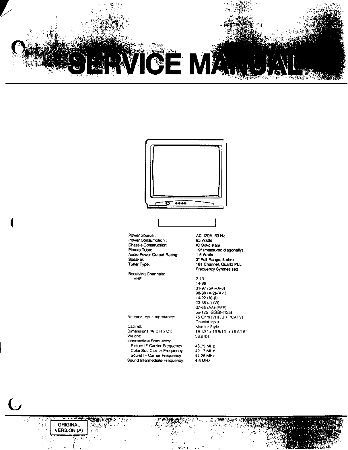
COLOR TELEVISION RECEIVER
TC1973D
Irr!
UHF
CATV
0 . . . .
1
SPECIFICATIONS
1
All the specifications and features are subject to change without notice.
Page 2
DISASSEMBLY INSTRUCTIONS
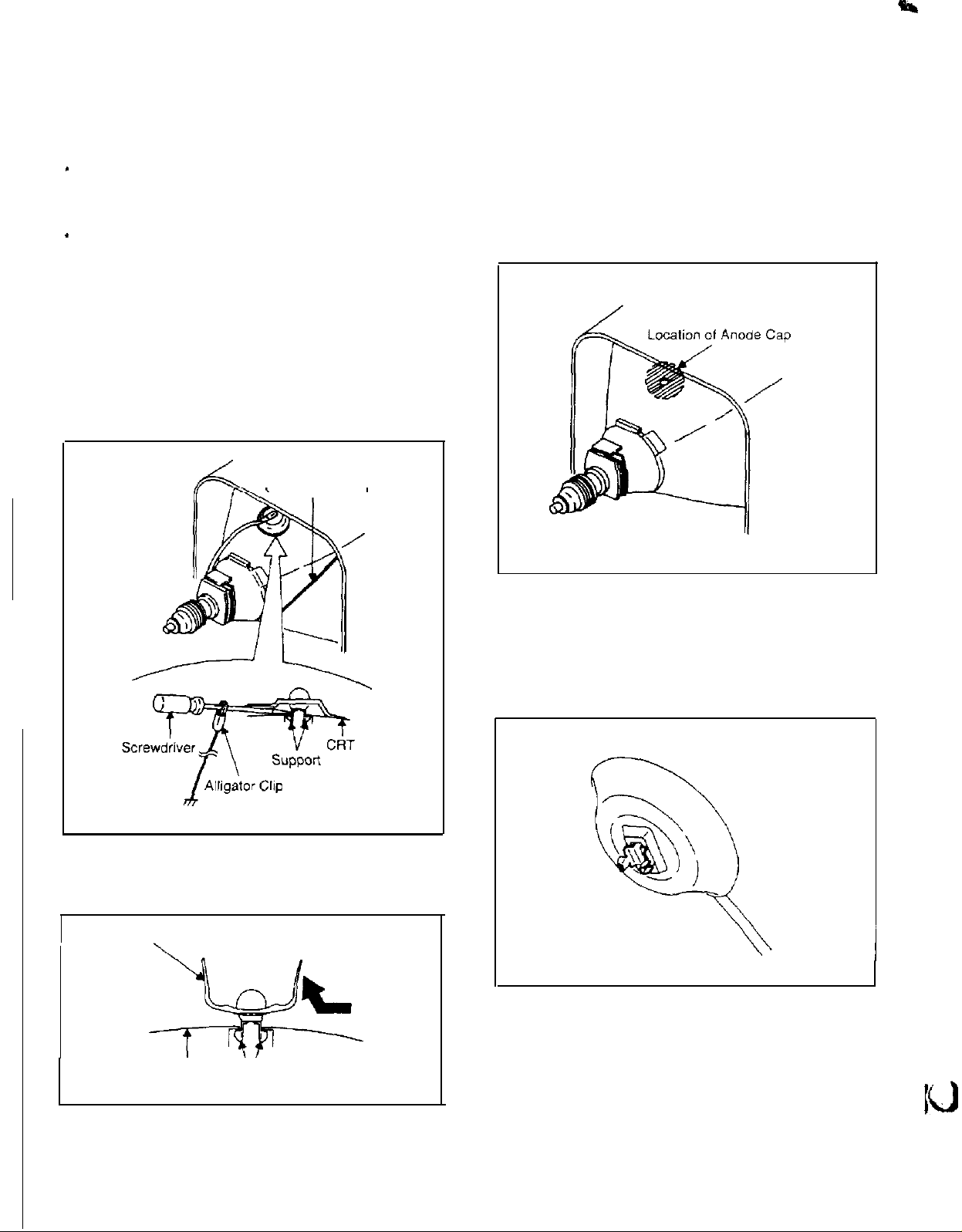
1. REMOVAL OF ANODE CAP
Read the following NOTED items before starling work.
After turning the power off there might still be a potential
voltage that is very dangerous. When removing the
Anode Cap, make sure to discharge the Anode Cap’s
potential voltage.
Do not use pliers to loosen or tighten the Anode Cap
’
terminal, this may cause the spring to be damaged.
REMOVAL
1.
Follow the steps as follows to discharge the Anode Cap.
(Refer to Fig. l-l.)
Connect one end of an Alligator Clip to the metal part of a
flat-blade
While holding the plastic part of the insulated Screwdriver,
touch the support of the Anode with the tip of the
Screwdriver.
A cracking noise will be heard as the voltage is discharged.
screwdriver and the other end to ground.
GND
on the CRT
3. After one side is removed. pull in the opposite direction to
remove the other.
NOTE
Take care not to damage the Rubber Cap.
INSTALLATlON
1. Clean the spot where the cap was located with a small
amount of alcohol. (Refer to Fig. l-3.)
GND on the CRT
2. Flip up the sides of the Rubber Cap in the direction
arrow and remove one side of the support
(Refer to Fig. l-2.)
Rubber Cap
Fig. 1-l
of
the
NOTE
Confirm that there is no dirt. dust, etc. at the spot where
the cap was located.
2. Arrange the wire of the Anode Cap and make sure the
wire is not twisted.
3. Turn over the Rubber Cap. (Refer to Fig. l-4.)
Fig. 1-4
CRT
V
Support
Fig.
1-2
4
Page 3
DISASSEMBLY INSTRUCTIONS
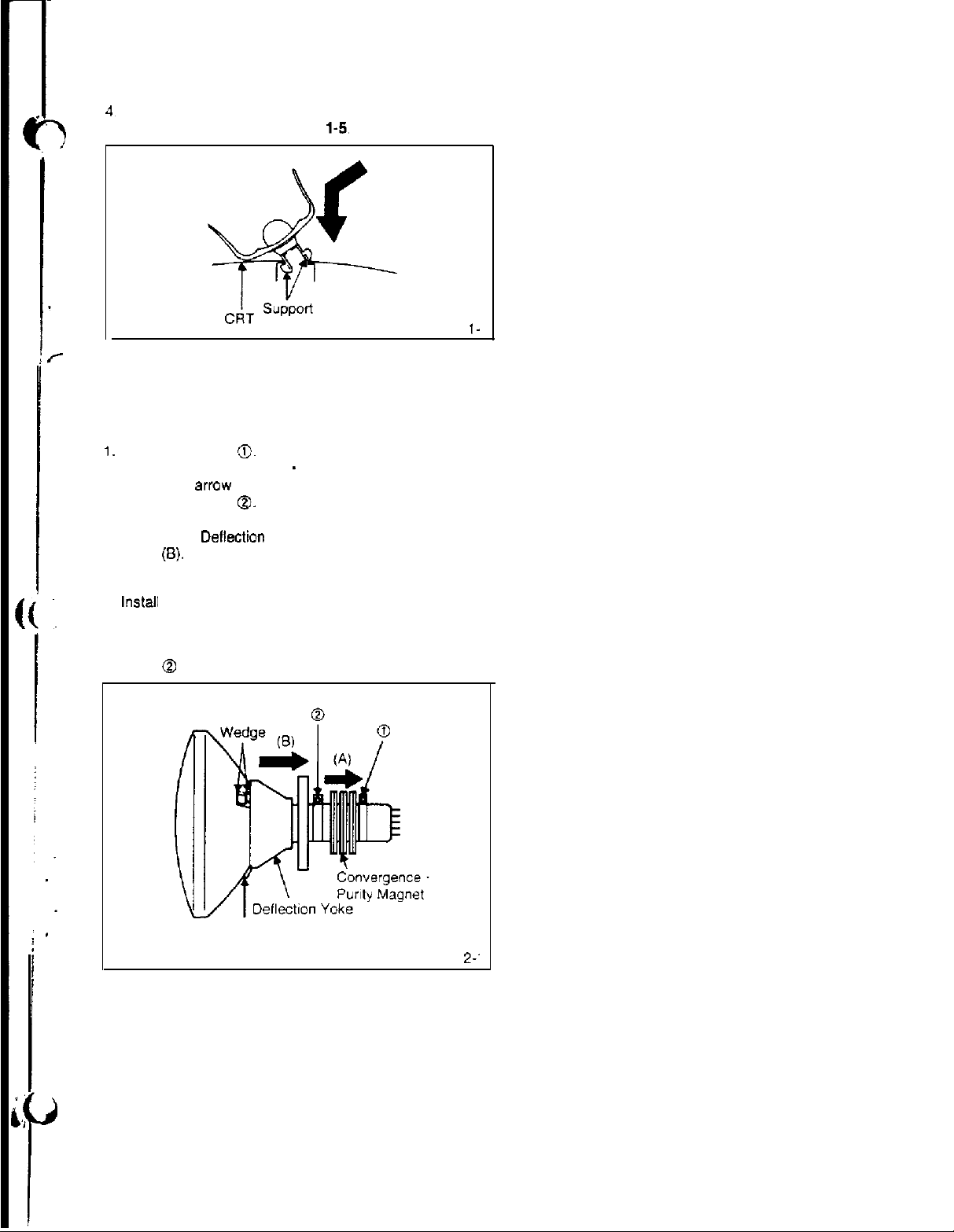
4,
Insert one end of the Anode Support into the anode button.
then the other as shown in Fig. I-5.
Fig.
5. Confirm that the Support is securely connected.
6. Put on the Rubber Cap without moving any parts.
2. REMOVAL OF DEFLECTION YOKE
(Refer to
I.
Loosen the screw
2. Remove the Convergence . Purity Magnet in the
direction of arrow (A).
3. Loosen the screw
4. Remove the 3 Wedges.
5. Remove the Dellection Yoke in the direction of
arrow
INSTALLATION
tnstall new Deflection Yoke in reverse steps of REMOVAL.
NOTE
After adjusting the purity and the convergence. fix the
screw 0 and lock the wedges.
Fig. 2-1)
0.
0.
(8).
l-
Wedge
Fig.
2-.
5
Page 4
ELECTRICAL ADJUSTMENTS
1. BEFORE MAKING ELECTRICAL
ADJUSTMENTS
Read and perform these adjustments when repairing the
circuits or replacing electrical parts or
CAUTION
Use an isolation transformer when performing any
sarvce
on this chassis.
Before removing the anode cap, discharge electricity
because it contains high voltage.
When removing a PCB or related component, after
unfastening or changing a wire, be sure to put the wire
back in its original position.
Inferior
sillcon
grease can damage
When replacing
silicon grease
Remove all old silicon before applying new silicon.
1-l: Prepare the following measurement tools far
electrical adjustments.
1.
Sweepmarker Generator
2. Oscilloscope
3. Digital Voltmeter
4. Color Bar Generator
IC’s
and transistors. use only specified
(YG6260M).
PC6
assemblies.
IC’s
and transistors.
L
CUTOFF
1.
VSIZE
2.
BRI.
AUTO
3.
X-RAY
4.
CONT
5.
END
8.
1.
AUTO
2. vco
3. AFT
4. AGC
5. COL
6. TINT
7.
BRI
8. END
Fig.
2-Z
f
,
.
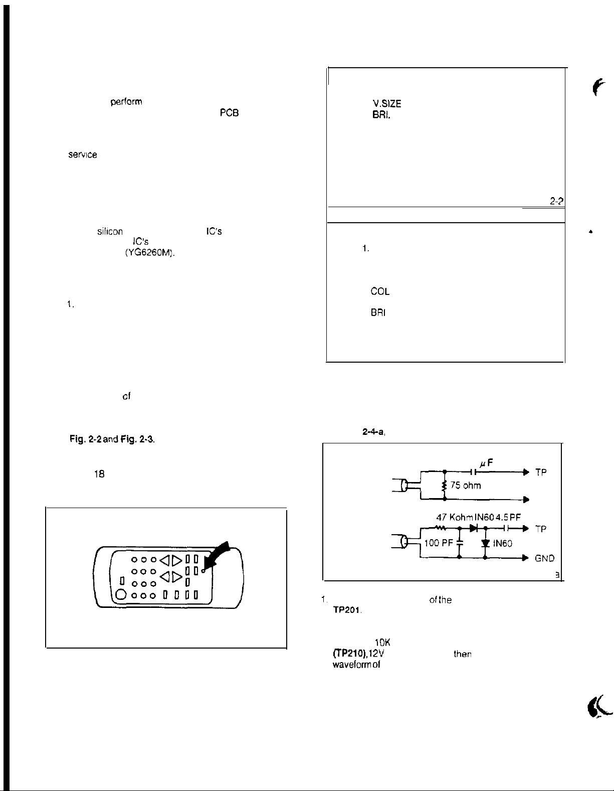
2. BASIC ADJUSTMENTS
On-Screen Display Adjustment
the of a straightened paper clip into the hole
on remote control marked with an arrow as shown
Fig. 2-f.
The adjustment mode display will appear as shown
Fig.2-2 andFig.2.3.
NOTE
Use the
options shown in Fig. 2-2 and Fig. 2-3.
Press the 8 key to end the adjustments.
1 8
keys on the remote control to select the
Fig. 2-l
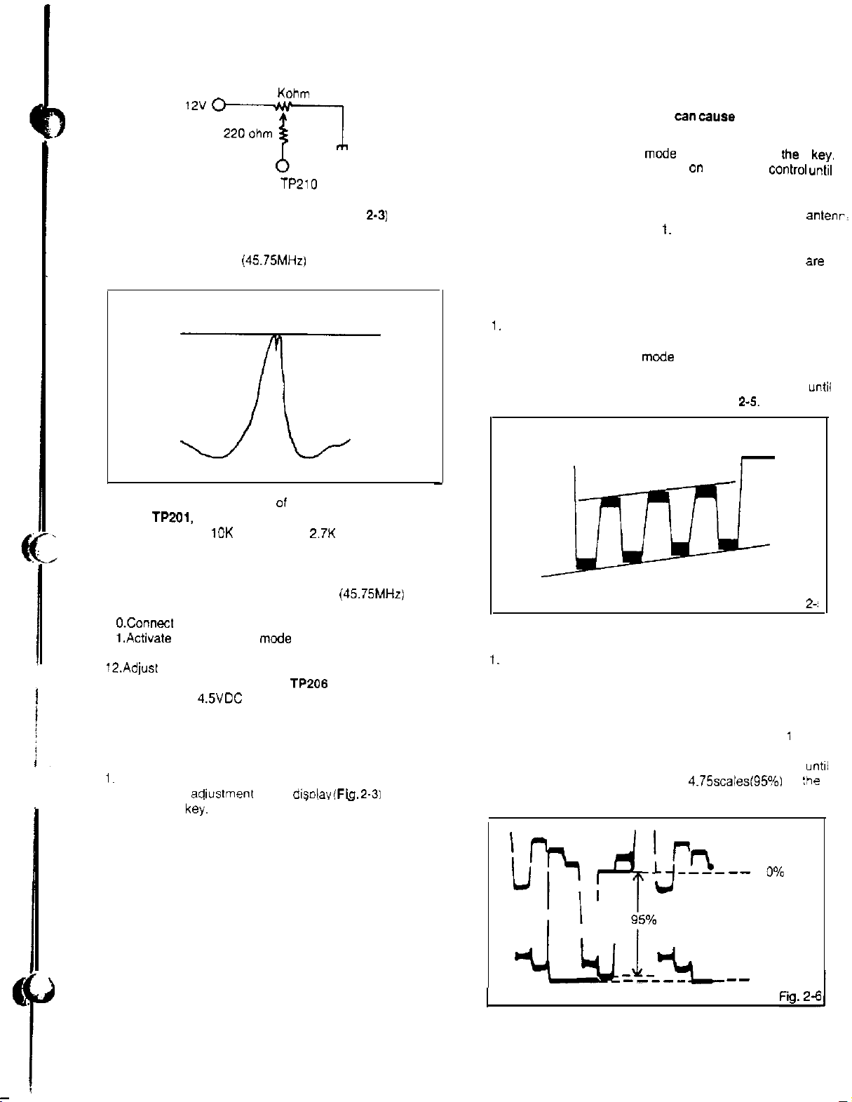
2-1: VCO AND AFT
NOTE
Connect input and output terminals of the
sweepmarker generator to the circuit as shown
in Fig.
2-4-a,
SWEEPMAKER
GENERATOROUTPUT
-
SWEEPMAKER
GENERATOR INPUT 47Kohm
1.
Connect output terminal of
TP201.
2. Connect input terminal of the sweepmarker generator to
TP204.
3. Connect a
(TP210). 12V
wavelorm 01 the oscilloscope readable
10K
ohm variable resistor to IF AGC terminal
line and ground. lhen adjust to make the
it.
0.22
rF
lN60 4.5 pF
Ihe
sweepmarker generator to
Fig. 2-3
GND
Fig. 2-4-z
3
Page 5
ELECTRICAL ADJUSTMENTS
10
Kohm
AGC TP210
4. Activate the adjustment mode display (Fig.
press the 2 key.
5. Adjust VOL. UP/DOWN key on the remote control until
the waveform maker
Fig. 2-4-b.
(45.75MHz)
45.75 MHz
becomes as shown in
2-3)
and
In case of strong electric field.
(Radio frequency interference can
streaks to appear.)
1. Activate the adjustment mcde display and press
2.
Press the VOL. UP/DOWN key 0” the remote
diagonal streaks are at minimum.
3. If there is still a problem after pressing the VOL. UP/DOWN
key on the remote control. install an attenuator to the
terminals. then repeat step
4. Confirm that noise does not appear.
5. Change the channel. confirm that the other channels are
normal.
2-2-C: TINT
1.
Receive the color bar pattern.
2. Connect the oscilloscope to TP023.
3. Activate the adjustment
the 6 key.
4. Press the VOL. UP/DOWN key on the remote control
the waveform becomes as shown in Fig.
mode
cause
diagonal
rhe
control untit
1.
display (Fig. 2-3) and press
2-5.
4
key.
antenr,
until
x
Fig. 2-4-t
6.
Disconnect output terminal 01 the sweepmarker generator
from
TP201,
then connect it to TP al the tuner pack.
7.
Disconnect the
resistors.
6.
Disconnect input and output terminals of the
sweepmarker generator.
9.
Connect the AFT adjustment oscillator
to TP of the tuner pack.
1 O.Connect the digital voltmeter to TP206.
1
l.Activate
the 3 key.
12.Adjust
2-2: BRIGHT, AGC, TINT AND COLOR
2-2-A: BRIGHT
1.
Receive the monochrome pattern.
2. Activate the adiustment mode displav
3. Press the VOL. UP/DOWN key on the remote control
2-2-B: AGC
NOTE
In case of weak electric field.
1. Tune to a noisy channel.
2. Activate the adjustment mode display and press
3. Press the VOL. UP/DOWN key on the remote control
4.
VOL. UP/DOWN key on the remote control to find
the point where the voltage of
and adjust to
press the 7
until the boundary between 0% and 10% white starts
to become visible.
Adjust after performing adjustments in section 2-1.
the 4 key.
until noise is at minimum.
Change the channel. confirm that the other channels
are normal.
10K
ohm and the
the adjustment
4.5VDC
ke;.
at that point.
2.7K
ohm variable
(45.75MHz)
mode
display (Fig. 2-3) and press
TP206
changes dramatically,
(Fig. 2-3)
,.
”
and
1
_
2-2-D: COLOR
1.
Receive the color bar pattern.
2. Connect the oscilloscope to TP022
3. Activate the adjustment mode (Fig. 2-3) display and press
the 5 key.
4. Adjust the VOLTS RANGE VARIABLE knob of the
oscilloscope until the range between white 0% and 1 CO%
is set to 5 scales on the screen of the oscilloscope.
5. Press the VOL. UP/DOWN key an the remote control
the red color level is adjusted to
white level. (Refer to Fig. 2-6)
4.75scalesf95%1
I
Fig.
2i
untii
for
:he
I
h-
J
k
b+4
LL
I
I
95%
I-_-_-
--OX
--
100%
7
Page 6
ELECTRICAL ADJUSTMENTS
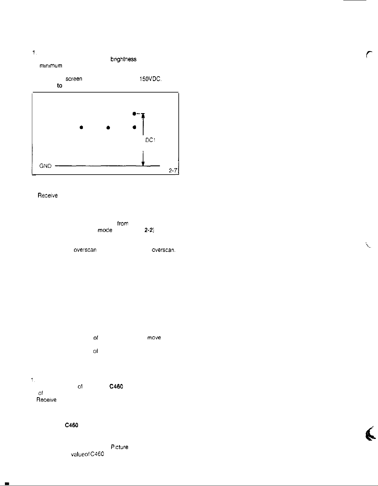
2-3: CUT OFF
1.
Receive the color bar pattern.
2. Using the remote control. set brightness and contrast to
mm~mum
3. Connect the oscilloscope to TP024.
4. Adjust the
(Refer to Fig. 2-7)
position.
screen
volume until voltage is
---.
.
.
.
15OVDC.
.-
--
*
.
I
DC1
50V
GND-
2-4: FOCUS
1.
Receive
2. Adjust the focus control until picture is distinct
the broadcasting signal.
Fig.
2-
I
7
1
2-5: VERTICAL SIZE
1.
Receive the crosshatch pattern
2. Activate the adjustment mcde display (Fig.
the 2 key.
3. Press the VOL. UP/DOWN key on the remote control until
the horizontal
2-6: VERTICAL POSITION
1. Receive the color bar pattern.
2.
Using the remote control, set brightness and contrast to
maximum position.
3. Adjust the value of R429 and R430 until horizontal line of
the color bar comes to approximate center of the CRT.
NOTE
R429 and R430 are fixed resistors. Use a variable
resistor to determine the optimal value and insert that
value resistor.
Lessen the value of R430
Lessen the value 01 R429
2-7: HORIZONTAL POSITION
1.
Receive the color bar pattern.
2. Adjust the value 01 R443 and
01
both screen edges are equal.
3. Receive the broadcasting signal, then confirm picture is
normal.
NOTE
R443 and
resistor or capacitor to determine the optimal value and
insert that value component.
Lessen the value of R443
Lessen the
overscan
C466
value 01
is equal to the vertical
are fixed components. Use a variable
C460
lrom
the color bar generator.
2-2)
and press
averscan.
Picture will
5mm UP.
Picture will move about
5mm DOWN.
C460
until the color width
Picture
will move right.
Picture Will move left.
move
about
8
Page 7
ELECTRICAL ADJUSTMENTS
3-3:
I
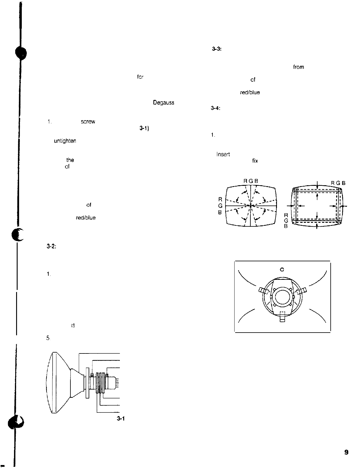
3. PURITY AND CONVERGENCE
ADJUSTMENT
NOTE
1. Turn the unit on and let it warm up
minutes before performing the following adjustments.
2. Place the CRT surface lacing east or west to reduce the
terrestrial magnetism.
3. Turn ON the unit and demagnetize with a
3-I: STATIC CONVERGENCE (ROUGH ADJUSTMENT)
1.
Tighten the
CRT for the position. (Refer to Fig.
If the deflection yoke and magnet are in one body,
untighten
2. Receive the green raster pattern from color bar
generator.
3. Slide
side 01 the CRT.
4. Adjust center of screen to green. with red and blue on the
sides, using the pair of purity magnets.
5. Switch the color bar generator from the green raster
pattern to the crosshatch pattern.
6. Combine red and blue of the 3 color crosshatch pattern
on the center ol the screen by adjusting the pair of
4 pole magnets.
7. Combine red/blue (magenta) and green by adjusting the
pair of 6 pole magnets.
6. Adjust the crosshatch pattern to change to white
by repeating steps 6 and 7.
3-2:
PURITY
NOTE
Adjust after performing adjustments in section 3-1.
1.
Receive the green raster pattern from color bar
generatar.
2. Adjust the pair of purity magnets to center the
color on the screen.
Adjust the pair of purity magnets so the color at ends are
equally wide.
3. Move the deflection yoke backward (To neck side)
slowly. and stop it at the position when the whole
screen IS green.
4. Confirm red and blue colors.
5~
Adjust the slant of the deflection yoke while watching the
screen. then tighten the fixing screw.
xrew
for the magnet. Refer to the adjusted
the screw for the body.
the
deflection yoke until it touches the funnel
for
at least 30
Degauss
3-l)
DEFLECTION YOKE
DEFLECTION YOKE SCREW
MAGNET SCREW
Coil.
STATIC CONVERGENCE
NOTE
1. Receive the crosshatch pattern lrom color bar generator.
2. Combine red and blue of the 3 color crosshatch pattern
on the center of the screen by adjusting the pair of
4 pole magnets.
3. Combine red/blue (magenta) and green by adjusting the
pair of 6 pole magnets.
3-4:
DYNAMIC CONVERGENCE
NOTE
Adjust after performing adjustments in section 3-3.
1.
Adjust the differences around the screen by moving
the deflection yoke upward/downward and right/left.
(Refer to Fig. 3-2-a)
2. insert three wedges between the deflection yoke and
CRT funnel to
(Refer to Fig. 3-2-b)
UPWARD/DOWNWARD SLANT
\
NEDGE
lix
the deflection yoke.
Fig. 3-2-a
0
WEDGE
WEDGE POSITION
Fig. 3-2-b
RIGHT/LEFT SLANT
/
WEDGE
Fig.
PURITY MAGNETS
6 POLE MAGNETS
4 POLE MAGNETS
3-l
9
Page 8

Page 9

Page 10

Page 11
Page 12

Page 13

Page 14

Page 15

Page 16

Page 17

Page 18

Page 19

Page 20

Page 21

Page 22

Page 23

Page 24

Page 25

Page 26

Page 27

Page 28

Page 29

Page 30

Page 31

Page 32

Page 33

Page 34

Page 35

Page 36

 Loading...