

Page 1
SERBIKE
MAWAL
‘,:, ”
TCl9i’m
CAUTION
Before
this
Servicing the chassis. read the “IMPORTANT SERVICE SAFETY INFORMATION” on
manual.
SPECIFICATIONS
SPEAKER
VOICE
ANTENNA
RECEIVING
UHF. . . . . . . . . . . . . . . . . . . . . . . . . . . . . . . . . . . . . . . . . . . . . . . . . . . . . . . . . . . . . . . . . . . . . . . . . . . .
CATV . . . . . . . . . . .
.
..Carrier
SoundIFCarrier
Color
WEIGHT
DIMENSIONSS
SIZEE
COILIMPEDANCE . . . .
. . . . . . . . . . . . . . . . . . . . . . . . . . . . . . . . . . . . 3-1/16"
INPUTT
IMPEDANCE . . . . . . . . . . .
CHANNELS
.
.
Sub -
........................................................................
Frequencyy...................
.......................
. . . . . . . . . . . . . . . . . . . . . . . . . . . .
Frequency
Frequency
...................................
...................................
....75
.
..................
,,:
6KHz
0.33
.
8ohms
ohm
.
.
.
0+/-3db
oz.
Magnet
at
600Hz
Coaxial
.
23-36 .
input
.14-69
.
.
.
14-22
.
(AA-FFF)
.
45 .75MHz
41
.25MHz
42
.17MHz
38
lbs
19’ REMOTE CONTROL COLOR
TELEVISION WITH ON-SCREEN
PICTURE CONTROLS
AKB
CCD
AUTOMATIC
KlNE
CLOSED CAPTION DECODER
CONTENTS
IMPORTANT
ELECTRICAL ADJUSTMENTS
1.
BEFORE MAKING ELECTRICAL ADJUSTMENTS
1-1.
2.
BASiC
2-1.
2-2:BRIGHT.
2.3:
2-4.
2-5.
2-6.
2-7.
3.
PURITY
3-1.
3.2:
3-3.
3-4:
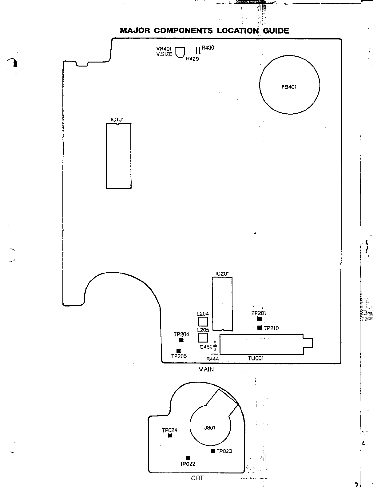
MAJOR
SEMICONDUCTOR
BLOCK
PRlNTED CIRCUIT
MAIN.
CRT/REMOCONN
SCHEMATIC DIAGRAMS
TUNERR
IF/MICON...
CHROMA
DEFLECTIONN
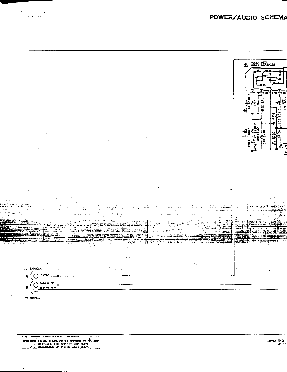
POWER/AUDIOO
MECHANICAL
MECHANlCAL
ELECTRlCAL
SERVICE SAFETY INFORMATION
PREPARE THE FOLLOWING
TOOLS FOR ELECTRICAL
AOJUSTMENTS
VIF
ANDD
AFT
. . . . . . . . . . . . . . . . . . . . . . . . . . . .
AGC.
CUT
OFF
FOCUS . .
VERTICAL
VERTICAL
HORIZONTAL POSITION
AND CONVERGENCE ADJUSTMENT
STATIC CONVERGENCE ROUGH ADJUSTMENTj
PURITYy
STATIC CONVERGENCE
DYNAMIC
COMPONENTS
DIAGRAM,
......................................................................
..........................................................................
...................................................................
........................................................................
..................................................................
EXPLODED VIEW.
REPLACEMENT
REPLACEMENT PARTS
TINT AND
............................ 5
SIZE
....................
POSITIONN
...............................................................
CONVERGENCE.
LOCATION GUIDEE
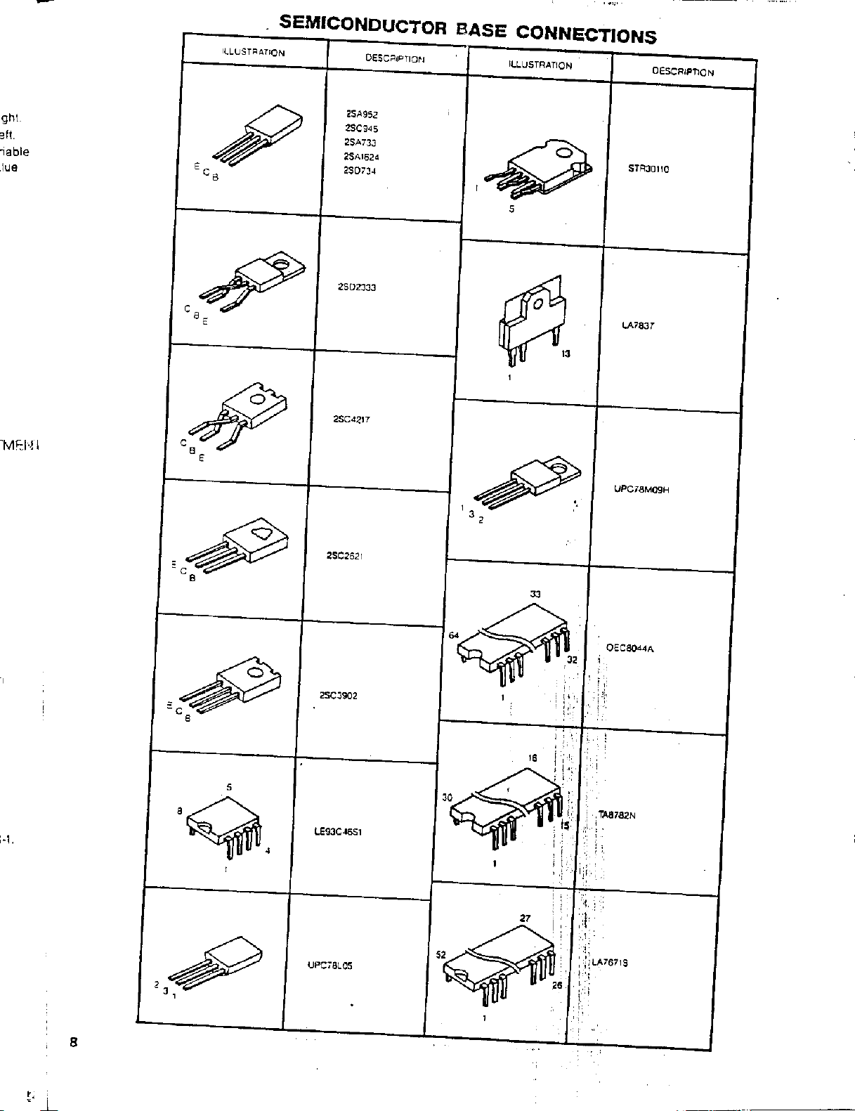
BASE
CONNECTIONSS
..............................................................
BOARDS
............................................................
............................................................
MEASUREMENT
ADJUSTMENTS ....
COLOR
............................................
....................
.......................................
.................................
............................
.............................
......................................... 7
PARTS LIST................. 8
LIST
......
page 2 of
BIAS
...................
.3.
4
...-............13. 19
...
10..
3
16
2
, ,
. 2
.
. 3
14
.
3
5
5
j
5
5
5
6
6
7
8
9
2
5
Page 2
ELECTRICAL ADJUSTMENTS
1. BEFORE MAKING ELECTRICAL
ADJUSTMENTS
Read and perform
the circuits or replacing electrical parts or
assemblies.
CAUTION
Use
an isolation transformer when performing
any service on lhis chassis.
Before removing the anode cap. discharge
electricity because it contains high voltage
When removing a
alter unfastening or changing a wire. be
put the
Inferior
transistors. When replacing
use only specified silicon grease
Remove all old silicon before applying new
silicon.
l-l:
Prepare the following measurement tools
wire
silicon grease can damage
for electrical
1. Sweepmarker Generator
2. Oscilloscope
3. Digital Voltmeter
4. Color Bar Generator
these
PCB
back in its original position.
adjustments
adjustments when repairing
or related component.
IC’s
and
IC’s
and transistors.
(YG6260M).
PCB
sure
to
ohm
1OK
12V
77
AGC TP210
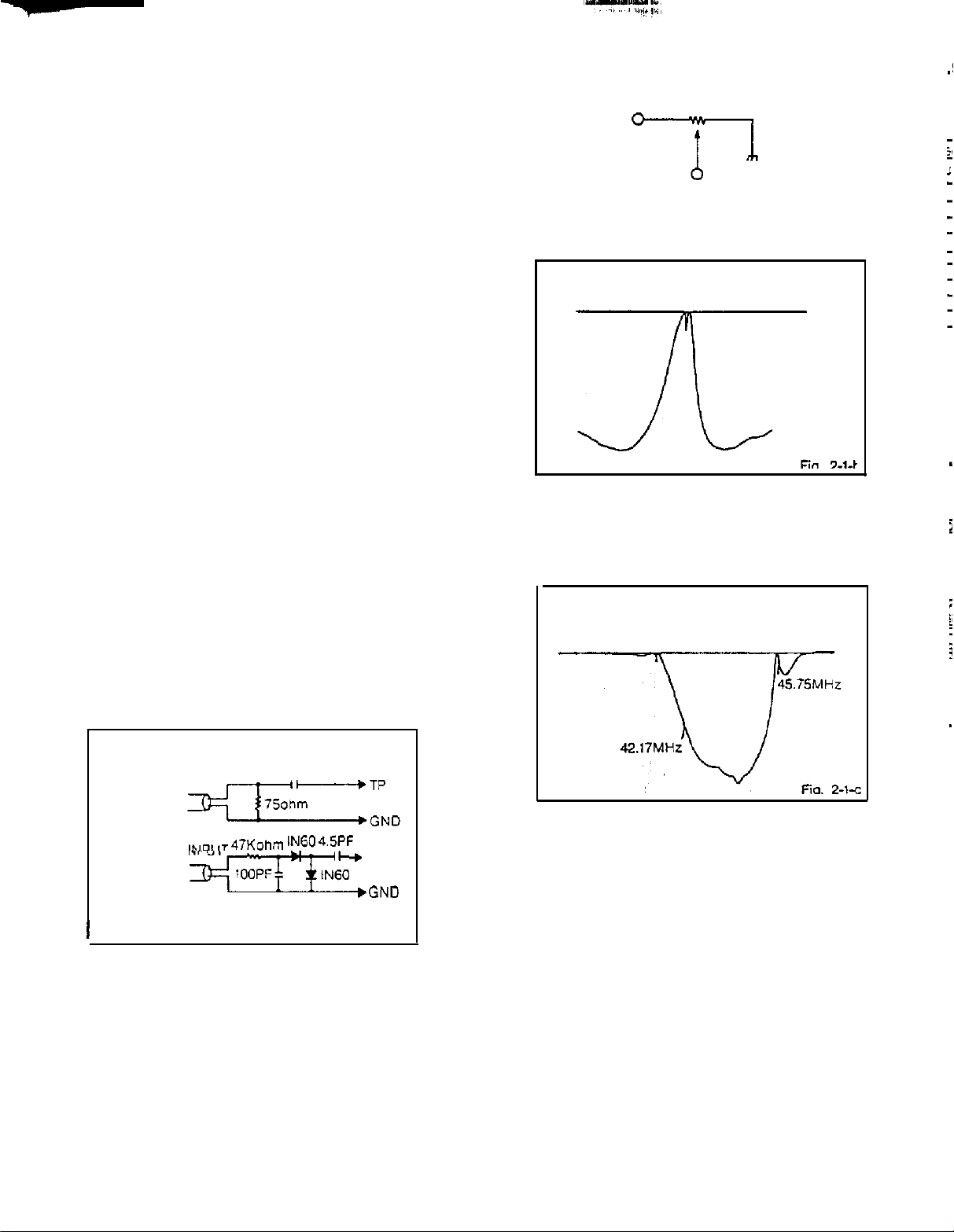
4. Adjust
becomes as shown in Fig. 2-l-b.
5,
6.
L205
until the waveform marker (45.75MHz)
45.75MHz
1
Disconnect output terminal of the sweepmarker
TP201.
generator from
of the tuner pack.
Adjust tuner pack coil until the
becomes as shown in Fig. 2-l-c.
then connect it to TP
waveform
BASIC ADJUSTMENTS
2.
2-1:
VIF AND AFT
NOTE
Connect input and output terminals of the
sweepmarket generator to the circuit as shown
in Fig. 2-l-a. then adjust it.
SWEEPMARKER
GENERATOR OUTPUT
SWEEPMARKER
GENERATOR
INPUT
-60
I
1. Connect output terminal of the sweepmarker
generator to TP201. (Connect a
resistor between them.)
2. Connect input terminal of the sweepmarker
to
generator
3. Connect a
terminal
adjust
oscilloscope readable.
TP204.
1OK
ohm variable resistor to IF AGC
(TP210). 12V
to make the waveform of the
line and ground. then
0.022.uF
47KohmIN60
2.7K
““E
ohm
TP
,GND
Fig. 2-1
41.24MHz
7
Disconnect the
and
2.7K
ohm resistor.
8.
Disconnect input and output terminals of the
sweepmarker generator.
Connect the AFT adjustment oscillator (45.75MHzl
9
to
TP,
of the tuner pack through a
a
resistor.
Connect the digital voltmeter to
10
11
Adjust
of
4.5VDC
L204
TP206
changes dramatically. and adjust to
at that point.
10K
ohm variable resistor
2.7K
ohm
TP206.
to find the point where the voltage
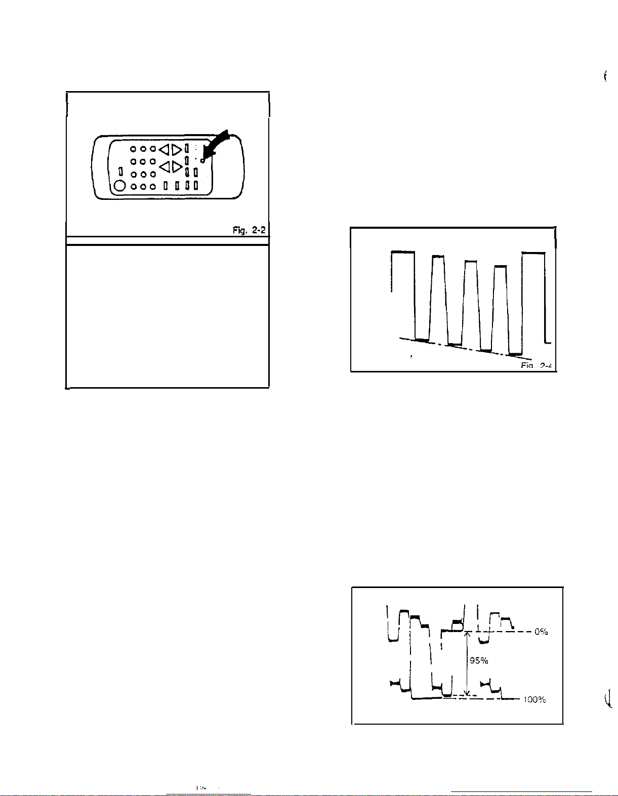
2-2: BRIGHT, AGC, TINT AND COLOR
On-Screen Display Adjustment
Insert
the point of a straightened paper clip into
the hole on, the remote control marked with
arrow as shown in Fig. 2-2.
The adjustment mode display will appear as
in
Fig.
2-3.
an
shown
3
Page 3
ELECTRICAL ADJUSTMENTS
NOTE
Use
the
1 -
7
keys on the remote control to Select
the options show” in Fig. 2-3.
Press the
7
key to end the adjustments
ADJUSTMENT MODE
1. AGC/BRIGHT/TINT/COLOR
2. SUB BRIGHT AUTO
3. AGC MANUAL
4. COLOR MANUAL
5. TINT MANUAL
6,
BRIGHT MANUAL
7.
END
AUTO
not
4. Confirm noise does
5. Change the channel. confirm other channels
are ‘normal.
2-2-C:
TINT
1.
Receive the color bar patter”.
2. Using the remote Control. set the brightness
and color to center position.
3. Using the remote control, set the contrast
to
maxlmum
4. Connect the
5. Activate the adjustment mode display and press
the 5 key.
6. Press the VOL. UP/DOWN key a” the remote
Control
Fig.
2-4
position.
oscilloscope
until
the waveform becomes as show” in
appear,
to TPO23.
I
c
2-2-A:
1. Receive the monochrome pattern
2. Activate the adiustment mode display and press
3. Press the VOL. UP/DOWN key on the remote
2-2-B.
NOTE
In case of weak electric field.
1. Tune to a noisy channel.
2. Activate the adjustment mode display and press
3. Press the VOL. UP/DOWN key a” the remote control
4. Change the channel. confirm other channels
I” case of strong electric field.
(Radio frequency interlerence can cause diagonal
1. Aclivate the adjustment mode display and press
2.
3. If there is still a problem after pressing the VOL.
BRIGHT
the 6 key.
control until 0% of gray scale will begins to lighten.
AGC
Adjust after performing adjustments in section 2-l
the 3 key.
until noise is at minimum.
are normal.
streaks to appear.)
the 3 key.
Press
the VOL. UP/DOWN key on the remote
control
until diagonal streaks are at minimum.
UP/DOWN key
an attenuator to
repeat step
on
the remote control. install
the
antenna
1.
terminals
Fig. 2-3
the”
2-2-D: COLOR
1.
Receive the color bar patter”,
2. Using the remote control, set the brightness
and tint to center position.
3. Using the remote control, set the contrast
maximim position
to
4. Connect the oscilloscope to
5. Activate the adjustment mode display and
the 4 key.
6. Adjust the VOLTS RANGE VARIABLE knob of
the oscilloscope until the range between
100%
and 0% is set to 5 scales a” the Screen
Ihe
oscilloscope.
of
7. Press the VOL. UP/DOWN key
control until the red color level is set to
the
4.75th
scale (95%) from while 0%.
(Refer
to Fig. 2-5)
TP022.
on
white
the remote
Fig. 2.5
press
4
Page 4
ELECTRICAL
ADJUSTMENTS
4. Confirm red
5. Adjust
watching the
/
/
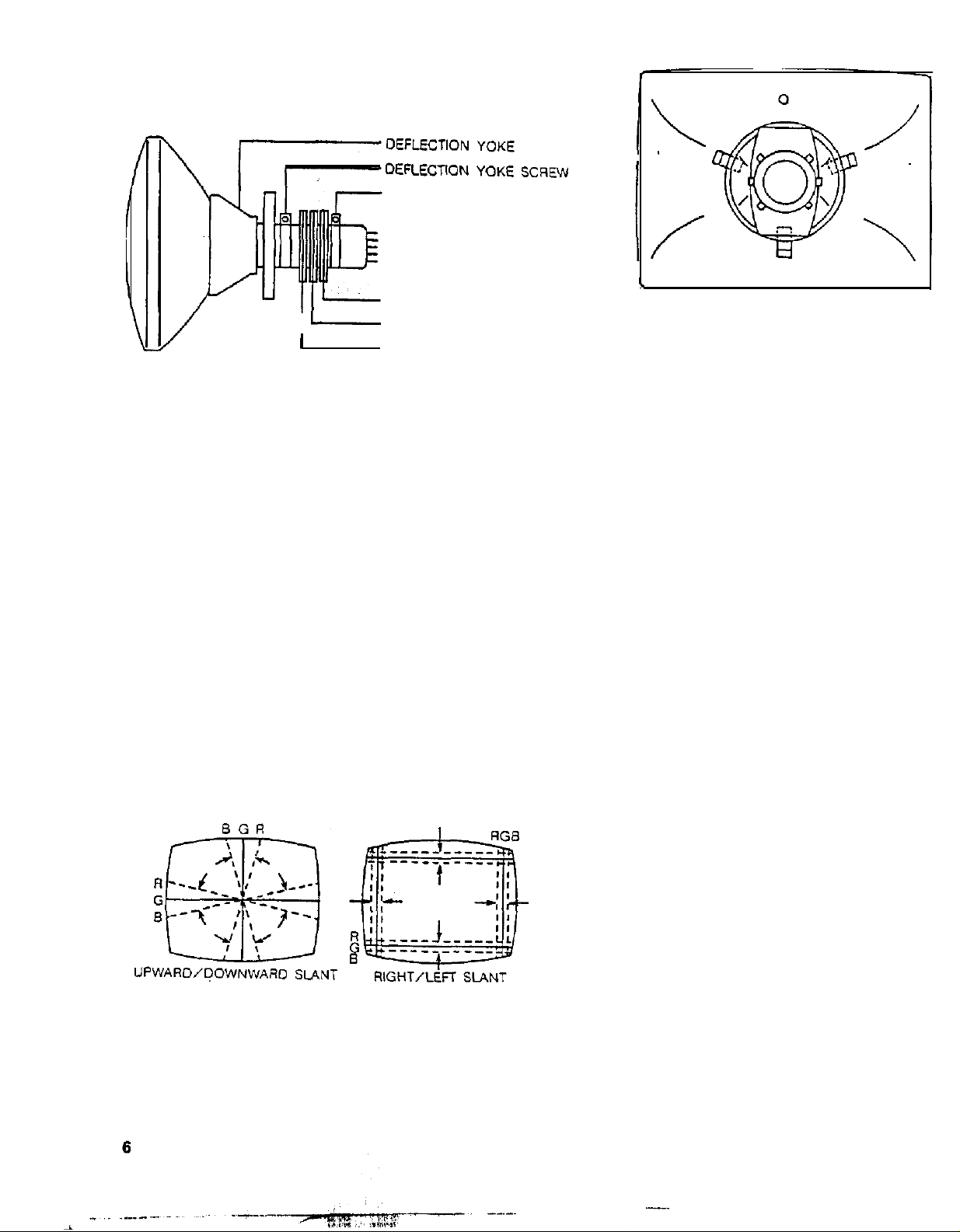
3-3:
STATIC CONVERGENCE
NOTE
Adjust after performing adjustmenls in section 3-2.
1. Receive the crosshatch pattern from
generator.
2. Combine red and blue of ‘the 3
pattern on the center of the screen by adjusting
the pair of 4 pole magnets.
3. Combine red/blue (magenta) and green by
adjusting the pair of 6 pole magnets.
the slant
and
blue
of
screen.
colors
Ihe
deflection yoke while
then
tighten
the fixing screw.
MAGNET
6 POLE MAGNETS
-
I
Fig.
4 POLE MAGNETS
PURITY MAGNETS
3-1
color
color
crosshatch
bar
SCREW
WEDGE
WEDGE
(
WEDGE POSITION
Fig. 3-2-b
WEDGE
3-4: DYNAMIC CONVERGENCE
NOTE
Adjust after performing adjustments in section 3-3.
1. Adjust the differences around the screen by moving
the deflection yoke upward/downward and
right/left. (Refer to Fig. 3-2-a)
2. Insert three wedges between the deflection yoke
and CRT funnel to fix the deflection yoke.
(Refer to Fig. 3-2-b)
Fig. 3-2-e
Page 5
ELECTRICAL ADJUSTMENTS
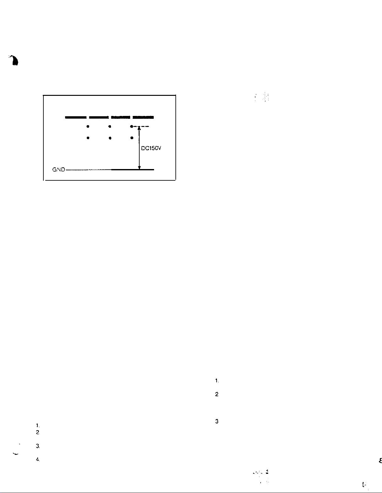
2-3: CUT OFF
1. Receive the color bar petter”.
2. Using the remote control. set brightness and
contrast to
3. Connect the oscilloscope to
4. Adjust the screen control until voltage is 150VOC.
(Refer to Fig. 2-6)
minimum
ON”
position.
--
,TPO24.
jiO”
Fig. 2-f
NOTE
Lessen the value of R444......Picture will move right.
Lessen the value of
R444
and
C460
resistor or capacitor to determine the optimal value
and insert that value component.
3.
PURITY
AND
C460 ,...,.Picture
are fixed components. Use a variable
will move left.
CONVERGENCE
ADJUSTMENT
NOTE
1. Turn the unit on and let it warm up for at
least
30 minutes before performing the
adjustments.
2. Place the CRT surface facing east or west to
reduce the terrestrial magnetism.
3. Turn ON the unit and demagnetize
degauss Coil,
followiiig
with
a
2-4: FOCUS
1. Receive the broadcasting signal.
2. Adiust the locus control until picture is distinct
2-5: VERTICAL SIZE
1. Receive the crosshatch petter” from the color
bar generator.
2. Adjust the bright and contrast controls until
the
crosshatch patter” is distinct.
3. Adjust VA401 until the center of crosshatch
is square.
4. Receive broadcasting signal, the” confirm
picture is
2-6: VERTICAL POSITION
1,
Receive the color bar patter”.
2. Using the remote control. set brightness and
Contrast Lo maximum position.
3. Adjust the value of A429 and
line of the color bar comes to approximate center
of the CRT.
NOTE
Lessen the value of R430......Picture will move about
Lessen the value of R429.....Picture will move about
R429 and R430 are fixed resistors. Use a variable
resistor to determine the optimal value and insert
that value resistor.
2-7:
Receive the color bar patter”.
Using
contrast to maximum position.
Adjust the value of
of both
Receive
picture
normal.
R430
until horizontal
5mm
UP.
5mm
DOWN.
HORIZONTAL POSITION
the remote control. set brightness and
R444
and
C460
until the color width
screen
edges are equal.
the broadcasting signal, the” confirm
is
normal.
3-1: STATIC CONVERGENCE (ROUGH
1. Tighten the screw for the magnet. Refer to the
adjusted
(Refer
If the deflection yoke and magnet are in one
body, untighten the screw for
2. Receive the green
bar generator.
3.
Slide the deflection yoke until it touches
funnel side of
4. Adjust center of screen to green. with red
and blue a” the sides, using the pair
purity magnets.
5. Switch the color bar generator from the
raster patter” to, the crosshatch
6. Combine red
Patter” on the
the pair of
7. Combine red/blue (magenta) and green by
adjusting the pair of 6 pole magnets.
8. Adjust the crosshatch petter” to change to
white by repeating steps 6 and 7.
3-2:
NOTE
Adjust after; performing adjustments in section 3-1
Receive
generator.
Adjust the pair of purity magnets to center
color on the screen.
Adjust the pair of purity magnets so the color
at ends are equally wide.
Move the deflection yoke backward (to
side) slowly, and Stop it at the position
the whole screen is green.
to
PURITY
CRT
for the position.
Fig. 3-1)
the
CRT.
and
center
4
pole magnets.
the green
raster petter” from color bar
the
raster
patter” from
pattern.
blue of the 3
of the screen by adjusting
ADJUSTMENT
body.
color
the
of
green
color crosshatch
the
neck
when
Page 6
Page 7
Page 8
Page 9

Page 10

Page 11

Page 12

Page 13

Page 14

Page 15

Page 16

Page 17

Page 18

Page 19

Page 20

Page 21

Page 22

Page 23

Page 24

Page 25

 Loading...