

Page 1
Instruction Manual
September 2013
Type FL
Type FL Relief Valve or Backpressure Regulator
WARNING
!
Failure to follow these instructions or to
properly install and maintain this equipment
could result in an explosion and/or re
causing property damage and personal injury
or death.
Tartarini™ regulators must be installed,
operated, and maintained in accordance
with federal, state, and local codes, rules
and regulations, and Emerson Process
Management Regulator Technologies, Inc.
(Regulator Technologies) instructions.
If the product vents gas or a leak develops in
the system, service to the unit may be required.
Failure to correct trouble could result in a
hazardous condition.
Call a gas service person to service the
unit. Only a quali ed person must install or
service the product.
Introduction
Scope of the Manual
This manual provides instructions for installation,
adjustment, maintenance, and parts ordering information
for the Type FL relief valve or backpressure regulator
with a Type PRX/182 pilot sold in North America. Any
accessories used with this relief valve or backpressure
regulator are covered in their respective manuals.
Description
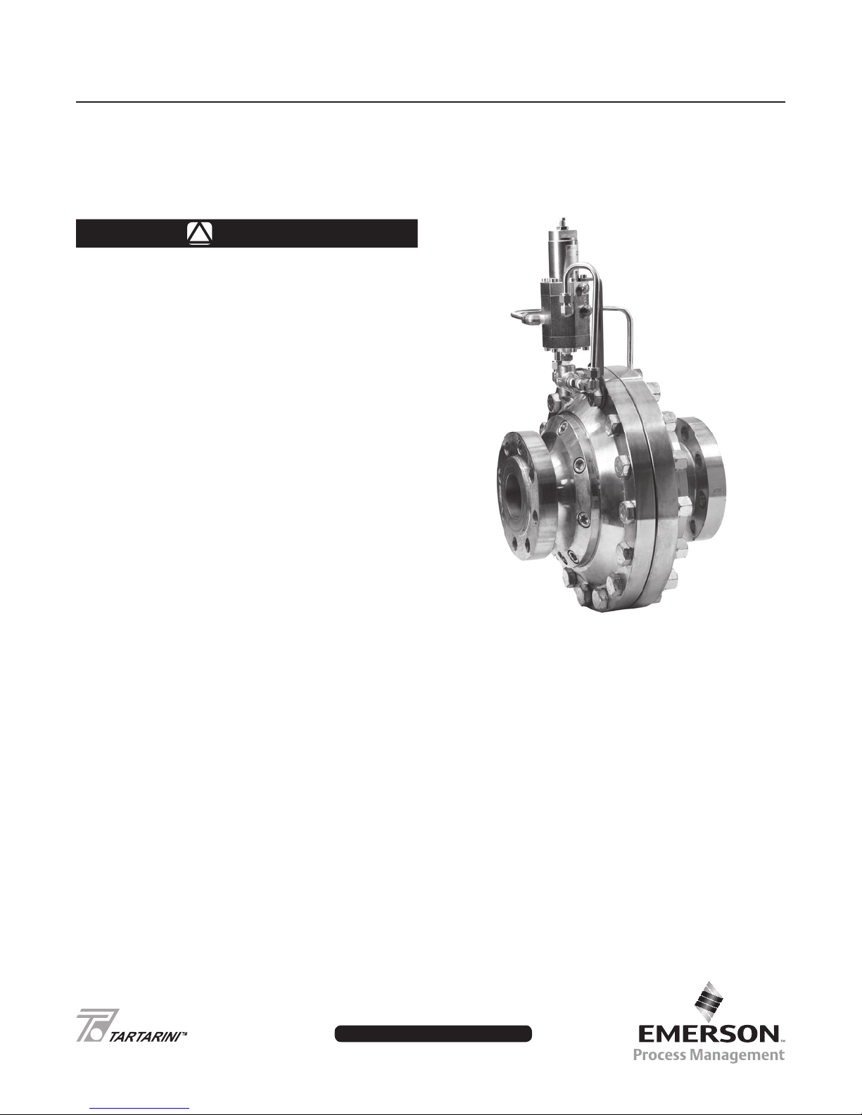
The Type FL relief valve or backpressure regulator are
accurate pilot-operated, relief valve or backpressure
regulators designed for high-pressure transmission/city gate,
large capacity distribution systems, and power plant feeds.
The Type FL relief provides smooth, reliable operation, tight
shutoff, and long life. The main valve actuator moves in
response to the pilot loading pressure to control upstream
system pressure.
Figure 1. Type FL Relief Valve or Backpressure Regulator
with PRX Series Pilot
Principle of Operation
A pressure relief valve is a throttling pressure control
device that opens and closes to ensure the inlet pressure
does not rise above a predetermined pressure. Tartarini™
relief valves cannot be used as ASME safety relief valves.
A backpressure regulator is a device that controls and
responds to changes in the upstream pressure. It functions
the same as a relief valve in such a way that it opens on
increasing upstream pressure.
Relief Valve
As long as the inlet pressure is below the set pressure,
the pilot control spring keeps the pilot valve plug closed. Inlet
pressure passes through the restrictor and registers as loading
pressure on the main valve diaphragm chamber. Force from
D103582X012
www.tartarini-naturalgas.com
Page 2
Type FL
Specications
The Specications section gives some general specications for the Type FL relief valve or backpressure regulator.
The nameplates give detailed information for a particular relief valve or backpressure regulator as it comes from
the factory.
Body Sizes
Type FL: NPS 1, 2, 3, 4, 6, 8, and 10 /
DN 25, 50, 80, 100, 150, 200, and 250
Main Valve End Connection Style and
Pressure Ratings
CL300 RF: 740 psig / 51.0 bar
CL600 RF: 1480 psig / 102 bar
(1)
(3)
(3)
Maximum Inlet and Outlet (Casing) Pressure
1480 psig / 102 bar
(3)
Minimum Buildup Pressure (Refer to Table 2)
Set Pressure Ranges
See Table 2
(1)
Temperature Capabilities
Nitrile (NBR) or Fluorocarbon (FKM) Disk:
-4 to 140°F / -20 to 60°C
Nitrile (NBR) Disk:
-20 to 140°F / -29 to 60°C
Approximate Weights (Including Pilot)
Type FL
NPS 1 / DN 25: 68 pounds / 31 kg
NPS 2 / DN 50: 132 pounds / 60 kg
NPS 3 / DN 80: 326 pounds / 148 kg
NPS 4 / DN 100: 443 pounds / 201 kg
NPS 6 / DN 150: 1058 pounds / 480 kg
NPS 8 / DN 200: 1367 pounds / 620 kg
NPS 10 / DN 250: 2623 pounds / 1190 kg
Pilot Spring Case Vent Connection
1/4 NPT tapping in pilot body
Pressure Registration
External through upstream control line. Pilot
spring case connection / Pilot body “B” port vent
connection 1/4 NPT tapping.
1. The pressure/temperature limits in this Instruction Manual and any applicable standard or code limitation should not be exceeded.
2. Type PRX Fluorocarbon (FKM) elastomer is limited to 0°F / -18°C.
3. At average ambient temperature.
4. Meets or exceeds ANSI/FCI 70-3 Class VI/VII leakage limits at maximum operating differential pressure.
(1)(2)
(4)
Table 1. Pilot Set Pressure Control
PILOT CONTROL INFORMATION
RELIEF SET
PILOT TYPE
PRX/182
PRX-AP/182 435 to 1160 30.0 to 80.0 GD27379X012 Clear 0.335 8.51 3.94 100 1160 80.0 1480 102
2
PRESSURE RANGE
Part Number Color
psig bar Inch mm Inch mm psig bar psig bar
29 to 116 2.0 to 8.0 GD25522X012 Black 0.157 3.99 2.16 54.9
73 to 290 5.0 to 20.0 GD25520X012 Gold 0.197 5.00 2.01 51.1
217 to 609 15.0 to 42.0 GD25519X012 Red 0.236 5.99 2.01 51.1
Wire Diameter Free Length
Maximum
Operating
Pressure
609 42.0
Maximum
Emergency
Pressure
1480 102
Page 3
Type FL
PORT B
EXHAUST
SPRING
CASE VENT
PORT A
PORT L
PORT S
PORT A
SPRING
CASE VENT
PORT B
EXHAUST
PORT L
PORT S
M1205
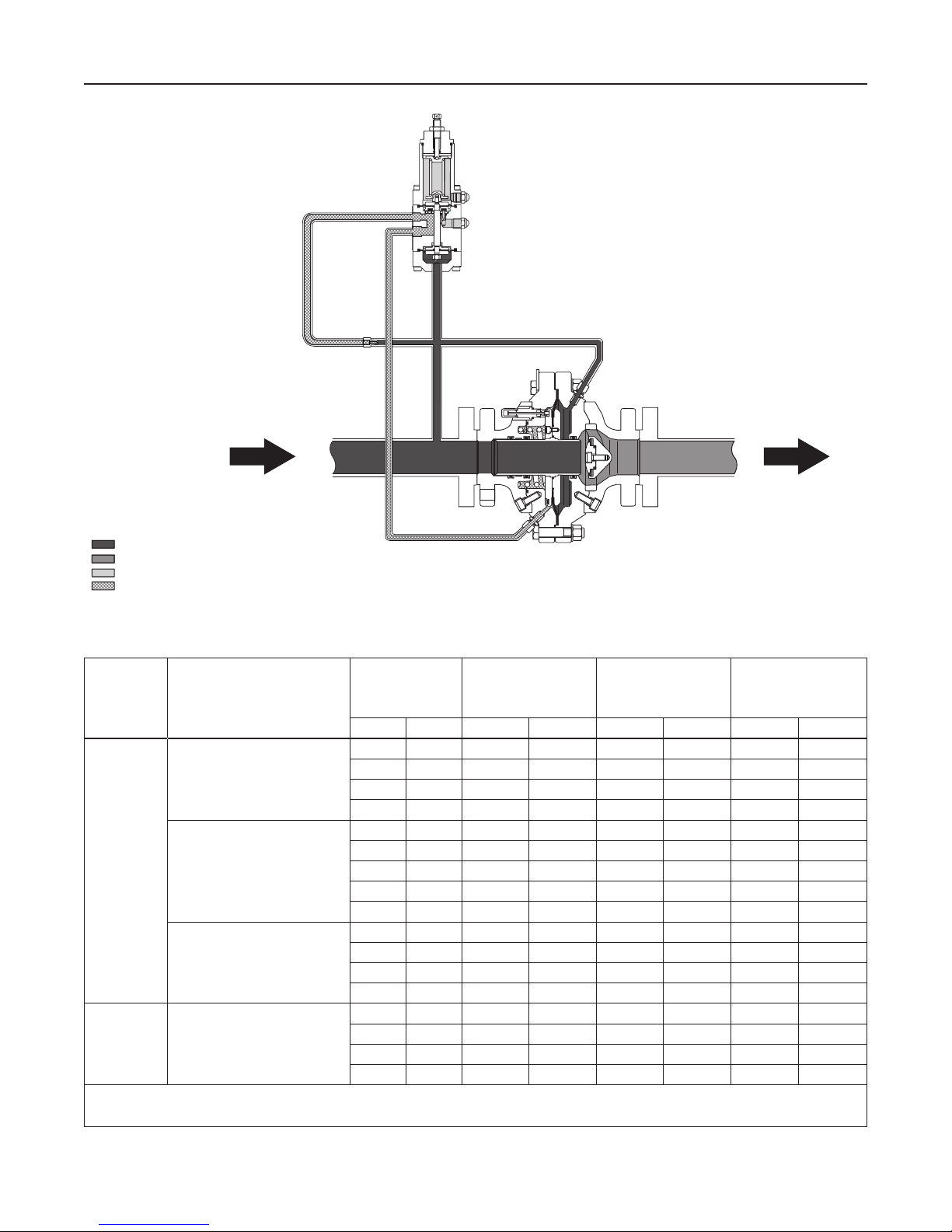
INLET PRESSURE
OUTLET PRESSURE
ATMOSPHERIC PRESSURE
LOADING PRESSURE
Figure 2. Type FL Relief Valve or Backpressure Regulator Operational Schematic
Table 2. Pilot Set Pressure Build Up
BUILD-UP OVER
SET PRESSURE
PILOT TYPE
SET PRESSURE CONTROL
RANGE, SPRING PART NUMBER
AND COLOR
SET PRESSURE
(1)
NEEDED TO BEGIN
OPENING VALVE
(2)
psig bar psig bar psig bar psig bar
30 2.1 1.2 0.08 2.8 0.19 1.0 0.69
PRX/182
29 to 116 psig / 2.0 to 8.0 bar
GD25522X012
Black
73 to 290 psig / 5.0 to 20.0 bar
GD25520X012
Gold
60 4.1 1.7 0.12 3.7 0.26 1.0 0.69
80 5.5 1.9 0.13 4.0 0.28 1.0 0.69
100 6.9 2.8 0.19 5.0 0.35 1.0 0.69
75 5.2 2.3 0.16 5.1 0.35 2.1 0.14
100 6.9 2.5 0.17 5.9 0.41 2.1 0.14
150 10.3 3.5 0.24 6.8 0.47 2.1 0.14
200 13.8 4.0 0.28 8.0 0.55 2.1 0.14
250 17.2 4.0 0.28 8.9 0.61 2.1 0.14
225 15.5 4.0 0.28 10.2 0.70 2.7 0.19
217 to 609 psig / 15.0 to 42.0 bar
GD25519X012
Red
300 20.7 4.0 0.28 10.5 0.72 2.7 0.19
400 27.6 4.1 0.28 10.7 0.74 2.7 0.19
450 31.0 4.3 0.30 11.0 0.76 2.7 0.19
450 31.0 4.3 0.30 11.0 0.76 3.3 0.23
PRX-AP/182
435 to 1160 psig / 30.0 to 80.0 bar
GD27379X012
Clear
500 34.5 4.5 0.31 11.1 0.77 3.3 0.23
600 41.4 5.1 0.35 11.1 0.77 3.3 0.23
1050 72.4 5.1 0.35 11.1 0.77 3.3 0.23
1. Set Pressure is de ned as the pressure at which the pilot starts-to-discharge.
2. Crack Point Pressure of the main valve of the inlet pressure build-up over the set pressure at which the main valve starts audible ow.
3. Inlet pressure build-up over the set pressure for the main valve to achieve wide-open ow capacity.
BUILD-UP OVER
SET PRESSURE
NEEDED TO FULLY
OPEN MAIN VALVE
PRESSURE DROP
BELOW SET
PRESSURE NEEDED
(3)
TO RESEAT PILOT
3
Page 4

Type FL
the main spring, in addition to pilot loading pressure, provide
loading pressure to keep the main valve diaphragm and plug
assembly tightly shut off.
When the inlet pressure rises above the set pressure,
the pressure on the pilot diaphragm overcomes the pilot
control spring and opens the pilot valve plug. The pilot
then exhausts the loading pressure from the main valve
diaphragm chamber. The pilot continuously exhausts gas
when the inlet pressure is above the set pressure. The inlet
pressure unbalance overcomes the main spring force and
opens the diaphragm and plug assembly.
As the inlet pressure drops below the set pressure, the pilot
control spring closes the pilot valve plug and the exhaust to
atmosphere stops. Force from the main spring, along with pilot
loading pressure, pushes the diaphragm and plug assembly
onto the knife-edged seat, producing tight shutoff.
Backpressure Regulator
As long as inlet pressure remains below setpoint, the pilot
control spring keeps the pilot valve plug closed. Inlet pressure
passes through the upper port around the upper portion of the
valve plug and then through the hollow passage in that valve
plug. Force from the main spring, in addition to pilot loading
pressure, provide downward loading pressure to keep the main
valve diaphragm and plug assembly tightly shut off. When inlet
pressure rises above the set pressure, pressure on the pilot
diaphragm overcomes the control spring to close the upper
port and stroke the valve plug to open the lower port. The pilot
exhausts loading pressure from the main valve diaphragm
chamber. Inlet pressure unbalance overcomes the main spring
force to open the diaphragm and plug assembly.
or pressure-limiting devices to prevent service
conditions from exceeding those limits. Also,
be sure the installation is in compliance with
all applicable codes and regulations.
Additionally, physical damage to the relief
valve or backpressure regulator could break
the pilot off the main valve, causing personal
injury and property damage due to bursting
of pressure-containing parts. To avoid such
injury and damage, install the regulator in a
safe location.
1. Only personnel qualied through training and
experience should install, operate, and maintain a relief
valve or backpressure regulator. Before installation,
make sure that there is no damage to, or debris in
the main valve body or pilot. Also, make sure that all
tubing and piping are clean and unobstructed.
CAUTION
After assembly, check for shutoff and
leakage to atmosphere.
2. A Type FL relief valve or backpressure regulator may
be installed in any orientation, as long as ow through
matches the direction of the arrow on the main
valve body.
3. Apply a good grade of pipe compound to the external
pipeline threads for a screwed body, or use suitable
line gaskets for a anged body. Use approved piping
procedures when installing the valve.
While the main valve is throttling, the upper port of the pilot
stays closed. The pilot exhausts only when it repositions the
main valve. As inlet pressure drops below setpoint, the pilot
control spring overcomes the diaphragm force to stroke the
valve plug down to close the lower port and open the upper
port. Force from the main spring, along with pilot loading
pressure, pushes the diaphragm and plug assembly onto the
knife-edged seat, producing tight shutoff.
Installation
WARNING
!
Personal injury or equipment damage, due
to bursting of pressure-containing parts may
result if this relief valve or backpressure
regulator is overpressured or is installed
where service conditions could exceed the
limits given in the Specication section and
on the appropriate nameplate, or where
conditions exceed any rating of the adjacent
piping or piping connections. To avoid such
injury or damage, provide pressure-relieving
WARNING
!
When used in relief valve service, the Type FL
main valve and pilot both exhaust gas. In
hazardous or ammable gas service, personal
injury, death, or property damage may occur
due to re or explosion of vented gas that
has accumulated. To prevent such injury or
damage, provide piping or tubing to vent the
gas to a safe location. The exhaust piping
must be designed and installed to guard
against excessive ow restriction. This piping
must be protected against condensation or
debris that could clog it.
For safety during shutdown, vent valves
are required immediately upstream
and downstream of the main valve on a
backpressure or bypass installation.
4. If system operation during maintenance is required,
install isolating and vent valves as needed.
4
Page 5

Type FL
5. If the vent assembly (key 12, Figure 7) remains in the
pilot body, then it must be pointed down if possible or
otherwise protected. If the exhaust is to be piped to
the main valve exhaust or remotely vented, remove
the vent assembly and install tubing or piping into
the 1/4 NPT pilot exhaust connection. There are two
vent connections need to be piped away. Protect the
open end of the exhaust pipe by installing a screened
vent cap.
6. The pilot spring case vent (key 12, Figure 7) must be
kept open to atmospheric pressure. Protect the vent
assembly from icing, moisture, or debris that may cause
blockage, as required. To change the vent orientation,
twist the vent assembly in the spring case. To remotely
vent the pilot spring case, pilot body vent need to be pipe
away as well and install tubing or piping into the 1/4 NPT
spring case vent tapping. Protect the open end of the
vent line by installing a screened vent cap.
7. The Type PRX pilot connections are 1/4 NPT. Connect
the inlet control (sense) line from the “A” port, Figure 6
(key 55), on the bottom of the Type PRX pilot to a straight
run of pipe 6 to 10 pipe diameters from the relief valve or
backpressure regulator inlet as shown in Figure 2, using
3/8 inch / 9.5 mm or larger outside diameter tubing. If such
a distance is not practical, connect the control line away
from elbows, swages, nipples, or any area where abnormal
ow velocities occur.
Startup and Shutdown
CAUTION
If pressure is introduced rst to the main
valve before the pilot, the main valve may
go wide-open and subject the downstream
system to full inlet pressure.
Note
The maximum inlet pressure for specic
constructions are given in Table 1. Use a
pressure gauge to monitor inlet pressure
during startup.
Relief Installation
Startup
1. Close vent valve (not shown).
2. Slowly open block valve and hand valve, if installed.
3. Adjust the pilot as needed.
Shutdown
1. Close block valve and hand valve, if installed.
2. Slowly open vent valve (not shown).
Backpressure Installation
Startup
1. Close upstream and downstream vent valves
(not shown).
2. Slowly open upstream block valve rst and then slowly
open downstream block valve.
3. Adjust the pilot as needed. If the pilot is not piped
downstream, make sure the pilot exhaust is pointed in
the correct direction.
Shutdown
1. Close upstream block valve rst and then close the
downstream block valve.
2. Open downstream and upstream vent valves
(not shown).
Pilot Adjustment (See Figure 7)
If set pressure adjustment is necessary, monitor relief (inlet)
pressure with a gauge during the adjustment procedure.
Loosen the locknut (key 2). Turn the adjusting screw (key 1)
into the spring case to increase the set pressure. Turn
the adjusting screw out of the spring case to decrease the
set pressure. When adjustment is completed, tighten the
locknut to lock the adjusting screw in position.
The adjustment of the relief valve or backpressure
regulator is performed by means of the pilot adjusting
screw, which varies the compression of the control spring.
Maintenance
The relief valve and backpressure regulator parts are subject to
normal wear and must be inspected periodically and replaced
as necessary. The frequency of inspection and replacement
depends on the severity of service conditions and on applicable
federal, state and local codes and regulations. Use only
replacement parts manufactured or furnished by Tartarini™.
WARNING
!
To avoid personal injury or property damage
from sudden release of pressure, isolate
the relief valve or backpressure regulator
from the pressure system, and release all
pressure from the pilot and main valve before
performing maintenance operations.
To prevent personal injury or damage to the
equipment during storage, installation or
maintenance operations, proper supports
shall be used to keep the Type FL relief valve
or backpressure regulator from rolling while
it is sitting on a at surface.
5
Page 6

Type FL
38
TOP VIEW
L1
37A
LEGACY TRAVEL INDICATOR DETAIL
40
34
38
36
35
33
L1
S1
L1
38
TOP VIEW
37B
IMPROVED TRAVEL INDICATOR DETAIL
40
34
38
36
66
35
33
L1
S1
P1764
APPLY LUBRICANT (L) / SEALANT (S)
L1 = LITHIUM HYDROXYSTEGRATE NLGI 2 GRADE GREASE
S1 = ANAEROBIC METHACRYLATE SEALANT FOR NUTS AND BOLTS
1. Lubricant and sealant must be selected such that they meet the temperature requirements.
(1)
:
Figure 3. Type FL Travel Indicator Assembly
Main Valve (Refer to Figure 5)
Main Valve Pad/Disk Replacement
1. Remove outlet ange (key 22) by removing socket head
screws (key 5).
2. Remove pad/disk holder assembly and O-ring (key 18).
For NPS 8 and 10 / DN 200 and 250, the pad/disk
holder remains attached to the outlet ange and no
dismounting is necessary.
3. Remove pad/disk (key 20) from pad/disk holder
(key 19) by removing socket head screw (key 25)
and pad/disk retainer (key 21), replace pad/disk
if necessary.
4. Reinstall the pad.
5. Reassemble in reverse order. Refer to Table 3 for torque
values. Tighten all bolts using a star pattern and repeat
2 to 3 times to ensure proper torque.
Main Valve Diaphragm Maintenance
1. Place main valve with inlet side up.
2. Remove the travel indicator assembly by removing the
indicator cover (key 40) and indicator bushing (key 38).
Check O-ring (key 37B), replace if necessary. Remove
the indicator support (key 36). Check O-ring (key 35),
replace if necessary. Lift out indicator stem assembly
(keys 33 and 34).
3. Remove inlet ange (key 1) by removing socket head
cap screws (key 5). Due to force created by the spring
(key 6), take care when removing inlet ange.
4. Lift out spring (key 6). Remove hex head cap screws,
washers, and nuts (keys 9, 14, and 15). Lift off the
inlet cover (key 11).
5. Remove diaphragm assembly by removing screws
(key 27) to separate the outlet and the inlet plates
(keys 12 and 8). Check diaphragm (key 10) and O-rings
(keys 26 and 28) for damage and replace if necessary.
6
Page 7

Type FL
Check sleeve (key 16) seating surface for damage. Check
O-rings (keys 3 and 4) and anti-friction rings (key 2),
replace if necessary.
6. Reassemble in reverse order. Refer to Table 3 for torque
values. Tighten all bolts using a star pattern and repeat
2 to 3 times to ensure proper torque.
Type FL Travel Indicator Maintenance
A new and improved version of the travel indicator has
been phased in during 2013. The new version improves the
O-ring stem seal to minimize leakage and extend service
life. The components of the legacy and new versions are
not interchangeable. If maintenance is performed on the
travel indicator, it is recommended to replace the entire travel
indicator assembly with the new version. Part numbers for
the assemblies are shown in the parts list. Figure 3 shows
the difference between the designs. The spare parts kits will
support either design. Take care to use the correct O-ring
(key 37A or 37B) when performing maintenance, see parts list
for the appropriate part number.
1. Remove plastic travel indicator cover (key 40).
2. Loosen travel indicator bushing (key 38) and remove it
by sliding it over the travel indicator stem (key 34).
3. Remove indicator tting (key 36) and inspect O-ring
(key 35). Remove O-ring (key 37B) and back-up rings
(key 66). Replace and lubricate O-ring if damaged.
Pull up on the travel indicator stem (key 34) to force the
spring collet (key 33) out of the diaphragm head groove.
Examine these parts and the stem for wear and replace
if necessary.
4. Insert the travel indicator stem (key 34) and spring
collet (key 33) back into the diaphragm head groove.
Replace the indicator tting (key 36) and O-ring
(key 35) and tighten with a reference torque of
3.7 foot-pounds / 5.0 N•m.
5. Lubricate the O-ring (key 37B) and back-up rings
(key 66, 2 required). Place one back-up ring on the
stem (key 34) followed by the O-ring and then the other
back-up ring. Push into groove of the indicator tting
(key 36).
6. Slide the travel indicator bushing (key 38) over the
travel indicator stem (key 34) and tighten rmly
in place.
7. Replace the travel indicator cover (key 40) and tighten
rmly in place.
Type PRX/182 Pilot Maintenance (Figure 7)
Lower Diaphragm Maintenance
1. Disconnect pilot and remove it from the line.
2. Remove machine screws (key 10) from lower cover
(key 21) and the separate lower cover from the body
(key 16).
3. Use a wrench to hold the stem (key 23) and break loose
the stem nut (key 20). Remove the stem nut and washer
(key 11).
4. Remove the diaphragm plate (key 13), diaphragm
(key 14), lower diaphragm plate (key 15), and O-ring
(key 18). Inspect parts for damage or wear, replace
if necessary.
5. Lightly lubricate the O-ring (key 25). Place O-ring
over the stem (key 23) and press it down into the body
(key16).
6. Lightly lubricate the rims of the diaphragm (key 14) and
place it on top of the lower diaphragm plate (key 15).
Set the diaphragm plate (key 13) on the diaphragm
(key 14).
7. Lightly lubricate the O-ring (key 18) and place it in the
lower cover (key 21).
8. Place the washer (key 11) and stem nut (key 20) on
the stem (key 23) and tighten. If also performing Upper
Case Maintenance, skip to step 2 of the Upper Case
Maintenance section.
9. Insert washers (key 11) and machine screws (key 10) in
the lower cover (key 21) and tighten uniformly to ensure
proper seal.
Upper Diaphragm Maintenance
1. Disconnect pilot and remove it from the line.
2. Loosen locknut (key 2) and back out adjusting screw
(key 1) until compression is removed from the spring.
Remove cap (key 3).
3. Lift the upper spring seat (key 6), spring (key 7), and
O-ring (key 4) out of the spring case (key 8). Inspect
O-ring and replace if necessary.
4. Remove the machine screws (key 10) and the washers
(key 11), separate the spring case (key 8) from the body
(key 16), and lift the lower spring seat (key 9) away from
upper diaphragm nut (key 26). Use a wrench to hold
stem (key 23) securely while removing the upper
diaphragm nut.
CAUTION
Always remove spring (key 7) tension before
performing maintenance on this unit. To
remove spring tension, loosen locknut (key 2)
and back out adjusting screw (key 1) until
compression is removed from the spring.
5. Remove remaining loose components: washer
(key 11), upper diaphragm plate (key 13), diaphragm
(key 14), disk holder (key 22), and O-ring (key 18).
Inspect diaphragm and O-ring for damage or wear,
and replace if necessary.
7
Page 8

Type FL
6. Remove orice (key 19) and O-ring (key 17). Inspect
the parts for damage or wear, and replace if necessary.
Lightly lubricate the O-ring and place in the body (key 16).
Install the orice.
7. Set the disk holder (key 22) in the body (key 16).
8. Lightly lubricate the rims of the diaphragm plate (key 14).
Position the diaphragm convolution facing down, make
sure that the diaphragm is not deformed and is properly
installed. Take the diaphragm (key 14) and place it in the
body (key 16) on top of the disk holder (key 22).
9. Set the upper diaphragm plate (key 13) on top of the
diaphragm (key 14).
10. Place washer (key 11) and stem nut (key 26) on the stem
(key 23) and tighten using a wrench to hold the stem.
11. Place the upper spring seat (key 9) on the upper
diaphragm nut (key 26) and mount the spring case
(key 8) on top of the body (key 24) and the diaphragm
(key 14).
12. Place washers (key 11) and uniformly tighten the machine
screws (key 10) to hold the body (key 24) and spring case
(key 8) together.
13. Install spring (key 7) and upper spring seat (key 6) on
top of the lower spring seat (key 9) inside the spring case
(key 8). Install Cap (key 3).
14. Screw in adjusting screw (key 1) at desired spring
compression and use the lock nut (key 2) to lock the
adjusting screws position. Refer to Pilot Adjustment
section (page 5) to adjust pilot settings.
Parts Ordering
Each relief valve or backpressure regulator is assigned
a serial number, which can be found on the nameplate.
Refer to the number when contacting your local Sales
Ofce for technical information or when ordering parts.
When ordering replacement parts, reference the key number
of each needed part as found in the following parts list.
Separate kit containing all recommended spare parts
is available.
Parts List
Type FL Main Valve (Figure 5)
Key Description Part Number
Start-Up Repair Kit
(includes keys 4, 18, 20, 46, and 47.
Not all parts are used for all sizes.) See Table 4
Parts kit (includes keys 2, 3, 4, 10,
18, 20, 26, 28, 35, 37B, and 47.)
Not all parts are used for all sizes.) See Table 5
Travel Indicator Kit (includes keys 33, 34, 35,
36, 37B, 38, 39, and 40.) See Table 6
Key Description Part Number
1 Inlet Flange
CL300 RF
NPS 1 / DN 25 M0268280X12
NPS 2 / DN 50 M0268410X12
NPS 3 / DN 80 M0268520X12
NPS 4 / DN 100 M0268580X12
NPS 6 / DN 150 M0298170X12
NPS 8 / DN 200 M0298330X12
NPS 10 / DN 250 ERCA01166A0
CL600 RF
NPS 1 / DN 25 M0268260X12
NPS 2 / DN 50 M0268430X12
NPS 3 / DN 80 M0268540X12
NPS 4 / DN 100 M0268600X12
NPS 6 / DN 150 M0298160X12
NPS 8 / DN 200 M0296890X12
NPS 10 / DN 250 ERCA01168A0
2* Anti-Friction Ring, Polytetrauoroethylene (PTFE)
NPS 1 / DN 25 (6 required) M0194530X12
NPS 2 / DN 50 (6 required) M0194690X12
NPS 3 / DN 80 (6 required) M0192170X12
NPS 4 / DN 100 (6 required) M0194830X12
NPS 6 / DN 150 (6 required) M0207640X12
NPS 8 / DN 200 (6 required) M0296300X12
NPS 10 / DN 250 (6 required) ERCA01177A0
3* O-ring, Fluorocarbon (FKM)
NPS 1 / DN 25 (3 required) M6020019X12
NPS 2 / DN 50 (3 required) M6020029X12
NPS 3 / DN 80 (3 required) M6020036X12
NPS 4 / DN 100 (3 required) M6020044X12
NPS 6 / DN 150 (3 required) M6020050X12
NPS 8 / DN 200 (3 required) M6020053X12
NPS 10 / DN 250 (3 required) ERCA04451A0
4* Body O-ring
Nitrile (NBR)
NPS 1 / DN 25 (2 required) M6010108X12
NPS 2 / DN 50 (2 required) M6010119X12
NPS 3 / DN 80 (2 required) M6010195X12
NPS 4 / DN 100 (2 required) M6010157X12
NPS 6 / DN 150 M6010084X12
NPS 8 / DN 200 M6010084X12
Fluorocarbon (FKM)
NPS 1 / DN 25 (2 required) M6020084X12
NPS 2 / DN 50 (2 required) M6020101X12
NPS 3 / DN 80 (2 required) M6020128X12
NPS 4 / DN 100 (2 required) M6020090X12
NPS 6 / DN 150 M6020072X12
NPS 8 / DN 200 M6020072X12
5 Socket Head Screw
NPS 1 / DN 25 (16 required) M5011044X12
NPS 2 / DN 50 (16 required) M5011062X12
NPS 3 / DN 80 (16 required) M5011086X12
NPS 4 / DN 100 (16 required) M5011094X12
NPS 6 / DN 150 (16 required) M5011115X12
NPS 8 / DN 200 (24 required) M5011115X12
NPS 10 / DN 250 (24 required) ERCA04502A0
6 Spring
NPS 1 / DN 25 M0194590X12
NPS 2 / DN 50 M0191440X12
NPS 3 / DN 80 M0192240X12
NPS 4 / DN 100 M0194880X12
NPS 6 / DN 150 M0249030X12
NPS 8 / DN 200 M0296460X12
NPS 10 / DN 250 ERCA01214A0
7 Tube Fitting - - - - - - - - - - 8 Inlet Plate
NPS 1 / DN 25 M0194440X12
NPS 2 / DN 50 M0194620X12
NPS 3 / DN 80 M0192080X12
NPS 4 / DN 100 M0194740X12
NPS 6 / DN 150 M0302910X12
NPS 8 / DN 200 M0302950X12
NPS 10 / DN 250 ERCA01164A0
9 Flange Bolt
NPS 1 / DN 25 (16 required) M5007026X12
NPS 2 / DN 50 (16 required) M5007045X12
NPS 3 / DN 80 (16 required) M5007077X12
NPS 4 / DN 100 (16 required) M5007100X12
NPS 6 / DN 150 (24 required) M5007141X12
NPS 8 / DN 200 (30 required) M5007193X12
NPS 10 / DN 250 (36 required) ERCA04503A0
*Recommended Spare Part
8
Page 9

Type FL
Key Description Part Number
10* Diaphragm, PVC Coated Nitrile (NBR)
NPS 1 / DN 25 GD19445X012
NPS 2 / DN 50 GD19463X012
NPS 3 / DN 80 GD19209X012
NPS 4 / DN 100 M0194750X12
NPS 6 / DN 150 M0238490X12
NPS 8 / DN 200 M0296620X12
NPS 10 / DN 250 ERCA01228A0
11 Inlet Body Cover
NPS 1 / DN 25 M0268640X12
NPS 2 / DN 50 M0268680X12
NPS 3 / DN 80 M0268720X12
NPS 4 / DN 100 M0268740X12
NPS 6 / DN 150 M0302930X12
NPS 8 / DN 200 M0302970X12
12 Outlet Plate
NPS 1 / DN 25 M0194480X12
NPS 2 / DN 50 M0194660X12
NPS 3 / DN 80 M0192120X12
NPS 4 / DN 100 M0194780X12
NPS 6 / DN 150 M0302920X12
NPS 8 / DN 200 M0302960X12
NPS 10 / DN 250 ERCA01135A0
13 Outlet Body Cover
NPS 1 / DN 25 M0268650X12
NPS 2 / DN 50 M0268690X12
NPS 3 / DN 80 M0268730X12
NPS 4 / DN 100 M0268750X12
NPS 6 / DN 150 M0302940X12
NPS 8 / DN 200 M0302980X12
NPS 10 / DN 250 ERCA01124A0
14 Washer
NPS 1 / DN 25 (16 required) M5001007X12
NPS 2 / DN 50 (16 required) M5001009X12
NPS 3 / DN 80 (16 required) M5001012X12
NPS 4 / DN 100 (16 required) M5001015X12
NPS 6 / DN 150 (24 required) M5001015X12
NPS 8 / DN 200 (30 required) M5001015X12
NPS 10 / DN 250 (36 required) ERCA00477A0
15 Nut
NPS 1 / DN 25 (16 required) M5002007X12
NPS 2 / DN 50 (16 required) M5002009X12
NPS 3 / DN 80 (16 required) M5002012X12
NPS 4 / DN 100 (16 required) M5002014X12
NPS 6 / DN 150 (24 required) M5002014X12
NPS 8 / DN 200 (30 required) M5002014X12
NPS 10 / DN 250 (36 required) ERCA04504A0
16 Sleeve
NPS 1 / DN 25 M0247720X12
NPS 2 / DN 50 M0230761X12
NPS 3 / DN 80 M0230621X12
NPS 4 / DN 100 M0230631X12
NPS 6 / DN 150 M0238340X12
NPS 8 / DN 200 M0296700X12
NPS 10 / DN 250 ERCA01107A0
17 Tube Fitting - - - - - - - - - - 18* O-ring
Nitrile (NBR)
NPS 1 to 4 / DN 25 to 100 See Key 4
NPS 6 / DN 150 M6010083X12
NPS 8 / DN 200 M6010087X12
NPS 10 / DN 250 ERCA04457A0
Fluorocarbon (FKM)
NPS 6 / DN 150 M6020122X12
NPS 6 / DN 150 M6020122X12
NPS 10 / DN 250 ERCA04457A1
19 Disk Holder
Type FL
NPS 1 / DN 25 M0250720X12
NPS 2 / DN 50 M0242810X12
NPS 3 / DN 80 M0251580X12
NPS 4 / DN 100 M0251640X12
NPS 6 / DN 150 M0250550X12
NPS 8 / DN 200 M0296660X12
NPS 10 / DN 250 ERCA01119A0
20* Disk
Nitrile (NBR)
NPS 1 / DN 25 M0250770X12
NPS 2 / DN 50 M0242820X12
NPS 3 / DN 80 M0251650X12
NPS 4 / DN 100 M0251600X12
*Recommended Spare Part
Key Description Part Number
20* Disk (continued)
Nitrile (NBR) (continued)
NPS 6 / DN 150 M0250560X12
NPS 8 / DN 200 M0296690X12
NPS 10 / DN 250 ERCA01204A0
Fluorocarbon (FKM)
NPS 1 / DN 25 M0276650X12
NPS 2 / DN 50 M0276670X12
NPS 3 / DN 80 M0276690X12
NPS 4 / DN 100 M0276700X12
NPS 6 / DN 150 M0276710X12
NPS 8 / DN 200 M0298670X12
NPS 10 / DN 250 ERCA01209A0
21 Disk Retainer
Type FL
NPS 1 / DN 25 M0194520X12
NPS 2 / DN 50 M0230750X12
NPS 3 / DN 80 M0230591X12
NPS 4 / DN 100 M0230601X12
NPS 6 / DN 150 M0238350X12
NPS 8 / DN 200 M0296670X12
NPS 10 / DN 250 ERCA01114A0
22 Outlet Flange
Type FL
CL300 RF
NPS 1 / DN 25 M0268290X12
NPS 2 / DN 50 M0268420X12
NPS 3 / DN 80 M0268530X12
NPS 4 / DN 100 M0268590X12
NPS 6 / DN 150 M0298190X12
NPS 8 / DN 200 M0298310X12
NPS 10 / DN 250 ERCA01138A0
CL600 RF
NPS 1 / DN 25 M0268270X12
NPS 2 / DN 50 M0268440X12
NPS 3 / DN 80 M0268550X12
NPS 4 / DN 100 M0268610X12
NPS 6 / DN 150 M0298180X12
NPS 8 / DN 200 M0296880X12
NPS 10 / DN 250 ERCA01157A0
CL600 RF
NPS 1 x 4 / DN 25 x 100 M2006490X12
NPS 2 x 6 / DN 50 x 150 M2006494X12
NPS 3 x 10 / DN 80 x 250 M2006498X12
NPS 4 x 10 / DN 100 x 250 M2006500X12
NPS 6 x 12 / DN 150 x 300 M2007261X12
NPS 8 x 16 / DN 200 x 400 M2007621X22
23 Gasket
Type FL
NPS 1 / DN 25 M0136180X12
NPS 2 / DN 50 M0136210X12
NPS 3 / DN 80 M0136230X12
NPS 4 / DN 100 M0136250X12
NPS 6 / DN 150 M0136270X12
NPS 8 / DN 200 M0136280X12
NPS 10 / DN 250 M0136290X12
24 Spacer
Type FL
CL300 RF
NPS 1 / DN 25 M0267180X12
NPS 2 / DN 50 M0208080X12
NPS 3 / DN 80 M0208090X12
NPS 4 / DN 100 M0208100X12
NPS 6 / DN 150 M2007602X12
NPS 8 / DN 200 M2007604X12
NPS 10 / DN 250 M2007606X12
CL600 RF
NPS 1 / DN 25 M0267210X12
NPS 2 / DN 50 M0267230X12
NPS 3 / DN 80 M0267250X12
NPS 4 / DN 100 M0267260X12
NPS 6 / DN 150 M2007603X12
NPS 8 / DN 200 M2007605X12
NPS 10 / DN 250 M2007607X12
25 Socket Head Screw
Type FL
NPS 1 / DN 25 M5011015X12
NPS 2 / DN 50 M5011044X12
NPS 3 / DN 80 M5011061X12
NPS 4 / DN 100 M5011039X12
9
Page 10

Type FL
Key Description Part Number
25 Socket Head Screw (continued)
Type FL (continued)
NPS 6 / DN 150 M5011003X12
NPS 8 / DN 200 M5011005X12
NPS 10 / DN 250 M5011050X12
26* O-ring
Nitrile (NBR)
NPS 1 / DN 25 M6010029X12
NPS 2 / DN 50 M6010105X12
NPS 3 / DN 80 M6010115X12
NPS 4 / DN 100 M6010121X12
NPS 6 / DN 150 M6010226X12
NPS 8 / DN 200 M6010140X12
NPS 10 / DN 250 ERCA04464A0
Fluorocarbon (FKM)
NPS 1 / DN 25 M6020021X12
NPS 2 / DN 50 M6020095X12
NPS 3 / DN 80 M6020073X12
NPS 4 / DN 100 M6020098X12
NPS 6 / DN 150 M6020116X12
NPS 8 / DN 200 M6020117X12
NPS 10 / DN 250 ERCA04464A1
27 Socket Head Screw
NPS 1 / DN 25 (6 required) M5011005X12
NPS 2 / DN 50 (6 required) M5011014X12
NPS 3 / DN 80 (12 required) M5011140X12
NPS 4 / DN 100 (12 required) M5011125X12
NPS 6 / DN 150 (8 required) M5011043X12
NPS 8 / DN 200 (16 required) M5011125X12
NPS 10 / DN 250 (20 required) M5011125X12
28* O-ring
Nitrile (NBR)
NPS 1 / DN 25 M6010104X12
NPS 2 / DN 50 M6010116X12
NPS 3 / DN 80 M6010126X12
NPS 4 / DN 100 M6010132X12
NPS 6 / DN 150 M6010140X12
NPS 8 / DN 200 M6010212X12
NPS 10 / DN 250 ERCA04500A0
Fluorocarbon (FKM)
NPS 1 / DN 25 M6020120X12
NPS 2 / DN 50 M6020096X12
NPS 3 / DN 80 M6020127X12
NPS 4 / DN 100 M6020097X12
NPS 6 / DN 150 M6020117X12
NPS 8 / DN 200 M6020168X12
NPS 10 / DN 250 ERCA04500A1
29 Nameplate - - - - - - - - - - 30 Nameplate Sticker - - - - - - - - - - 31 Drive Screw (4 required)
NPS 1 / DN 25 GD50002X012
NPS 2 / DN 50 GD50002X012
NPS 3 / DN 80 GD50002X012
NPS 4 / DN 100 GD50002X012
NPS 6 / DN 150 GD50002X012
NPS 8 / DN 200 GD50002X012
NPS 10 / DN 250 M4500027X12
32 Flow Arrow - - - - - - - - - - 33 Spring Collet
NPS 1 / DN 25 M0192180X12
NPS 2 / DN 50 M0192180X12
NPS 3 / DN 80 M0192180X12
NPS 4 / DN 100 M0192180X12
NPS 6 / DN 150 M0192180X12
NPS 8 / DN 200 M0296750X12
34 Indicator Stem
NPS 1 / DN 25 ERSA01798A0
NPS 2 / DN 50 ERSA01788A0
NPS 3 / DN 80 ERSA01804A0
NPS 4 / DN 100 ERSA01796A0
NPS 6 / DN 150 ERSA01805A0
NPS 8 / DN 200 ERSA01797A0
35* O-ring
Nitrile (NBR)
NPS 1 to 4 / DN 25 to 100 M6010010X12
NPS 6 and 8 / DN 150 and 200 M6010012X12
NPS 10 / DN 250 M6010174X12
Fluorocarbon (FKM)
NPS 1 to 4 / DN 25 to 100 M6020004X12
NPS 6 and 8 / DN 150 and 200 M6020005X12
Key Description Part Number
36 Indicator Fitting
NPS 1 / DN 25 ERSA01820A0
NPS 2 / DN 50 ERSA01820A0
NPS 3 / DN 80 ERSA01822A0
NPS 4 / DN 100 ERSA01822A0
NPS 6 / DN 150 ERSA02569A0
NPS 8 / DN 200 ERSA01823A0
NPS 10 / DN 250 ERCA01198A0
37A* O-ring
Nitrile (NBR) M6010001X12
Fluorocarbon (FKM) M6020066X12
37B* O-ring
Nitrile (NBR) 1H2926X0032
Fluorocarbon (FKM) 1H2926X0022
38 Indicator Bushing ERSA02798A0
39 Indicator Scale M0201990X12
40 Indicator Cover
NPS 1 / DN 25 M0194580X12
NPS 2 / DN 50 M0194710X12
NPS 3 / DN 80 M0192220X12
NPS 4 / DN 100 M0194870X12
NPS 6 / DN 150 M0210910X12
NPS 8 / DN 200 M0210910X12
47* O-ring
Nitrile (NBR)
NPS 1 / DN 25 - - - - - - - - - - NPS 2 / DN 50 - - - - - - - - - - NPS 3 / DN 80 M6010102X12
NPS 4 / DN 100 M6010113X12
NPS 6 / DN 150 M6010123X12
NPS 8 / DN 200 M6010136X12
NPS 10 / DN 250 ERCA04501A0
Fluorocarbon (FKM)
NPS 1 / DN 25 - - - - - - - - - - -
NPS 2 / DN 50 - - - - - - - - - - -
NPS 3 / DN 80 M6020082X12
NPS 4 / DN 100 M6020124X12
NPS 6 / DN 150 M6020123X12
NPS 8 / DN 200 M6020166X12
NPS 10 / DN 250 ERCA04501A1
50 Mounting Bracket
Horizontal M0247660X12
Vertical M0247670X12
51 Lifting Bracket
Horizontal M0278560X12
Vertical M0278590X12
52 Pipe Nipple
Steel Fitting - - - - - - - - - - SST Fitting - - - - - - - - - - 53 Tube Elbow
Steel Fitting - - - - - - - - - - SST Fitting - - - - - - - - - - 54 Tube Connector
Steel Fitting - - - - - - - - - - SST Fitting - - - - - - - - - - 55 Pipe Cross
Steel Fitting - - - - - - - - - - SST Fitting - - - - - - - - - - 56 Tubing - - - - - - - - - - 57 Elbow 90° - - - - - - - - - - -
58 Orice Bleed GE01698X012
59 Eyebolt
NPS 6 / DN 150 (2 required) M5040008X12
NPS 8 / DN 200 (2 required) M5040007X12
NPS 10 / DN 250 (2 required) ERCA00481A0
60 Backing Ring (2 required) 1N659106242
61 Pin (NPS 6 / DN 150 only) (8 required) M0249050X12
62 Screw
NPS 8 / DN 200 only (6 required) M5007160X12
NPS 10 / DN 250 (6 required) ERCA04505A0
63 Washer
NPS 8 / DN 200 only (6 required) M5077001X12
NPS 10 / DN 250 (6 required) ERCA00478A0
64 Socket Head Screw
NPS 6 / DN 150 (16 required) M5011150X12
NPS 8 / DN 200 (20 required) M5011117X12
65 Spring Pin
NPS 8 / DN 200 and NPS 10 / DN 250 M4501106X12
*Recommended Spare Part
10
Page 11

PRX Series Pilots (Figure 7)
Key Description Part Number
Parts Kits
Elastomer Parts Kits (includes keys: 4, 5, 14,
17, 18, 25, and 28)
Type PRX/182
Nitrile (NBR) RPRX00X0N12
Fluorocarbon (FKM) RPRX00X0F12
Type PRX-AP/182
Nitrile (NBR) RPRX00X0N12
Fluorocarbon (FKM) RPRX00X0F12
1 Adjusting Screw GD25334X012
2 Locknut GD03600X012
3 Cap GD25335X012
4* Upper Cover
Nitrile (NBR) GD01017X012
Fluorocarbon (FKM) GD01017X022
5* O-ring
Nitrile (NBR) GD01000X012
Fluorocarbon (FKM) GD01000X022
6 Spring Carrier Plate GD25336X012
7 Spring See Table 1
8 Upper Cover GD29854X012
9 Spring Carrier Plate GD25338X012
10 Machine Screw M5011018X12
11 Washer GD05500X012
12 Filter GD50036X012
13 Diaphragm Plate GD25339X012
14* Diaphragm
Nitrile (NBR) GG05785X012
Fluorocarbon (FKM) GG05785X022
15 Diaphragm Plate GD25341X012
16 Body GD25331X012
17* Orice O-ring
Nitrile (NBR) GD02012X012
Fluorocarbon (FKM) GD02012X022
18* Lower Cover O-ring
Nitrile (NBR) GD01009X012
Fluorocarbon (FKM) GD01009X022
19 Orice GD25344X012
20 Nut GD00200X012
21 Lower Cover GD29860X012
22* Pad Holder
Nitrile (NBR) GD25340X012
Fluorocarbon (FKM) M0279950X12
*Recommended Spare Part
Type FL
Key Description Part Number
23 Stem GD25343X012
24 Nameplate GD26808X012
25* Stem O-ring
Nitrile (NBR) GD01022X012
Fluorocarbon (FKM) GD01022X022
26 Upper Diaphragm Nut GD02800X012
27 Damper Adjusting Screw with Hole GD25348X012
28* Restrictor/Damper O-ring GD02005X022
29 Damper/Restrictor Plate
Types PRX/182 and PRX-AP/182 GD25440X012
Types PRX/182 and PRX-AP/182 GD25793X012
31 Nameplate Screw GD06100X012
33 Plug (Types PRX/182 and PRX-AP/182) GD25792X012
34 Plug (Types PRX/182 and PRX-AP/182) GD50032X012
35 Spring Barrel Extension for AP GD27410X012
PRX Series Pilot Mounting Parts (Figure 6)
Standard Congurations for Single Pilot
Key Description Part Number
50 Mounting Bracket
Horizontal M0247660X12
Vertical M0247670X12
51 Lifting Bracket
Horizontal M0278560X12
Vertical M0278590X12
52 Pipe Nipple (4 required) - - - - - - - - - - 53 Tube Elbow (2 required) - - - - - - - - - - 54 Tube Connector (4 required) - - - - - - - - - - 55 Pipe Cross - - - - - - - - - - 56 Tubing - - - - - - - - - - 57 90° Pipe Elbow (2 required) - - - - - - - - - - -
58 Orice Bleed GE01698X012
BODY SIZE TORQUE
NPS DN
Flange Bolt (key 9) Socket Head Screw (key 5 / 64) Socket Head Screw (key 25) Socket Head Screw (key 27)
Foot-pound N•m Foot-pound N•m Foot-pound N•m Foot-pound N•m
1 25 51.6 70 14.7 20 8.11 11 4.42 6,0
2 50 73.6 100 22.1 30 36.9 50 5.16 7,0
3 80 258 350 59.0 80 66.4 90 5.16 7,0
4 100 295 400 73.8 100 66.4 90 11.8 16
6 150 295 400 51.6 70 147 199 20.0 27
8 200 295 400 51.6 70 147 199 14.7 20
10 250 435 590 111 150 148 200 14.7 20
Table 3. Maximum Torque Values
11
Page 12

Type FL
E0831
SPACER DETAILS
FOR SIZES SMALLER THAN
NPS 6 / DN 150
SOCKET HEAD SCREW
(KEY 5 OUTLET SIDE)
OUTLET FLANGE
(KEY 22)
DISK-HOLDER
(KEY 19)
SPACER DETAILS FOR
NPS 6 TO 12 / DN 150 TO 300
E0832
(KEY 4 OR 18 DEPENDING ON SIZE)
O-RING
Figure 4. Outlet Flange Spacer Installation
Table 4. Type FL Start-Up Repair Kit Part Numbers
DESCRIPTION MATERIAL NPS 1 / DN 25 NPS 2 / DN 50 NPS 3 / DN 80 NPS 4 / DN 100 NPS 6 / DN 150 NPS 8 / DN 200 NPS 10 / DN 250
Type FL, FL-SR,
or FL-SR/SRS
Type FL-SRII or
FL-SRII/SRS
Nitrile (NBR) M2600750X12 M2600754X12 M2600758X12 M2600762X12 M2600766X12 M2600948X12 ERCA00598A0
Fluorocarbon (FKM) M2600751X12 M2600755X12 M2600759X12 M2600763X12 M2600767X12 M2600988X12 ERCA00571A0
Nitrile (NBR) M2601115X12 M2601118X12 M2601121X12 M2601124X12 M2601127X12 M2601130X12 ERCA00598A0
Fluorocarbon (FKM) M2601114X12 M2601117X12 M2601120X12 M2601097X12 M2601098X12 M2601099X12 ERCA00571A0
Table 5. Type FL Parts Kit Part Numbers
DESCRIPTION MATERIAL NPS 1 / DN 25 NPS 2 / DN 50 NPS 3 / DN 80 NPS 4 / DN 100 NPS 6 / DN 150 NPS 8 / DN 200 NPS 10 / DN 250
Type FL, FL-SR,
or FL-SR/SRS
Type FL-SRII or
FL-SRII/SRS
Nitrile (NBR) GD89973X012 GD89972X012 GD89971X012 GD89970X012 GD89969X012 M2200948X12 ERCA00558A0
Fluorocarbon (FKM) GD89973X022 GD89972X022 GD89971X022 GD89970X022 GD89969X022 M2200988X12 ERCA00525A0
Nitrile (NBR) M2201115X12 M2201118X12 M2201121X12 M2201124X12 M2201127X12 M2201130X12 ERCA00558A0
Fluorocarbon (FKM) M2201114X12 M2201117X12 M2201120X12 M2201097X12 M2201098X12 M2201099X12 ERCA00525A0
12
Page 13

Type FL
5/64
4/18
22 23 24
26
27
28
12
293032313334353637383940
SPACER DETAILS
FOR SIZES SMALLER THAN
NPS 6 / DN 150
19
20
21
25
47
62
19
63
NPS 1 AND 2 / DN 25 AND 50
WITHOUT SILENCER
19
20
21
25
59
1
20
21
25
47
NPS 3, 4, 6, AND 8 /
DN 80, 100, 150, AND 200
WITHOUT SILENCER
30
31
9
35
36
37B
34
38
39
40
3
29
32
10
33
28
27
14
15
1331
5
18
3
NPS 10 / DN 250
WITHOUT SILENCER
59
22
24
23
19
20
21
25
47
2
6 16 82612
2
LM/1403
7
17
NPS 10 / DN 250
Figure 5. Type FL Main Valve Assembly (continued)
65
13
Page 14

Type FL
“S” PORT
53
56
53
55
52
50
“L” PORT
58
58
“A” PORT
54
FLOW
53
54
57
VENT
“B” PORT (VENT)
52
14
Figure 6. Type FL Single Pilot Mounting Assembly
Page 15

Type FL
35
4
4
35
4
4
A
A
22
19
17
16
18
1413
1
2
3
4
5
6
7
8
9
10
11
12
B
15
11
20
1
2
3
4
5
6
26
11
13
18
14
A
24
23
25
21
11
10
A
20
11
7
8
9
10
11
12
B
22
19
17
16
18
15
1413
S
34
28
L
B
34
28
31 29
4
35
4
Table 6. Type FL Travel Indicator Assemblies Part Numbers
DESCRIPTION MATERIAL NPS 1 / DN 25 NPS 2 / DN 50 NPS 3 / DN 80 NPS 4 / DN 100 NPS 6 / DN 150 NPS 8 / DN 200 NPS 10 / DN 250
Travel Indicator
Plug Only - - - -
Fluorocarbon
(FKM)
ERSA01557A0 ERSA01558A0 ERSA01559A0 ERSA01561A0 ERSA01569A0 ERSA01572A0 ERCA00489A0
CODE PORT DESCRIPTION
A Upstream Control Line
B Exhaust Port
S Connect to Inlet Body Cover
L Connect to Outlet Body Cover
Figure 7. Types PRX/182 and PRX-AP/182 Pilots
Plug: M0305570X12
O-ring: M6020004X12
Table 7. Type PRX/182 Connections
GD89907X012
Plug: ERCA04404A0
O-ring: ERCA00488A0
15
Page 16

Type FL
Industrial Regulators
Emerson Process Management
Regulator Technologies, Inc.
USA - Headquarters
McKinney, Texas 75069-1872, USA
Tel: +1 800 558 5853
Outside U.S. +1 972 548 3574
Asia-Pacic
Shanghai 201206, China
Tel: +86 21 2892 9000
Europe
Bologna 40013, Italy
Tel: +39 051 419 0611
Middle East and Africa
Dubai, United Arab Emirates
Tel: +971 4811 8100
For further information visit www.emersonprocess.com/regulators
The Emerson logo is a trademark and service mark of Emerson Electric Co. All other marks are the property of their prospective owners. Tartarini is a mark of O.M.T. Ofcina Meccanica Tartarini s.r.l.,
a business of Emerson Process Management.
The contents of this publication are presented for informational purposes only, and while every effort has been made to ensure their accuracy, they are not to be construed as warranties or
guarantees, express or implied, regarding the products or services described herein or their use or applicability. We reserve the right to modify or improve the designs or specications of such
products at any time without notice.
Emerson Process Management Regulator Technologies, Inc. does not assume responsibility for the selection, use or maintenance of any product. Responsibility for proper selection, use and
maintenance of any Emerson Process Management Regulator Technologies, Inc. product remains solely with the purchaser.
Natural Gas Technologies
Emerson Process Management
Regulator Technologies, Inc.
USA - Headquarters
McKinney, Texas 75069-1872, USA
Tel: +1 800 558 5853
Outside U.S. +1 972 548 3574
Asia-Pacic
Singapore 128461, Singapore
Tel: +65 6770 8337
Europe
Bologna 40013, Italy
Tel: +39 051 419 0611
Chartres 28008, France
Tel: +33 2 37 33 47 00
TESCOM
Emerson Process Management
Tescom Corporation
USA - Headquarters
Elk River, Minnesota 55330-2445, USA
Tels: +1 763 241 3238
+1 800 447 1250
Europe
Selmsdorf 23923, Germany
Tel: +49 38823 31 287
Asia-Pacic
Shanghai 201206, China
Tel: +86 21 2892 9499
©Emerson Process Management Regulator Technologies, Inc., 2012, 2013; All Rights Reserved
 Loading...