

Page 1

Product Data Sheet
00813-0100-3565, Rev AB
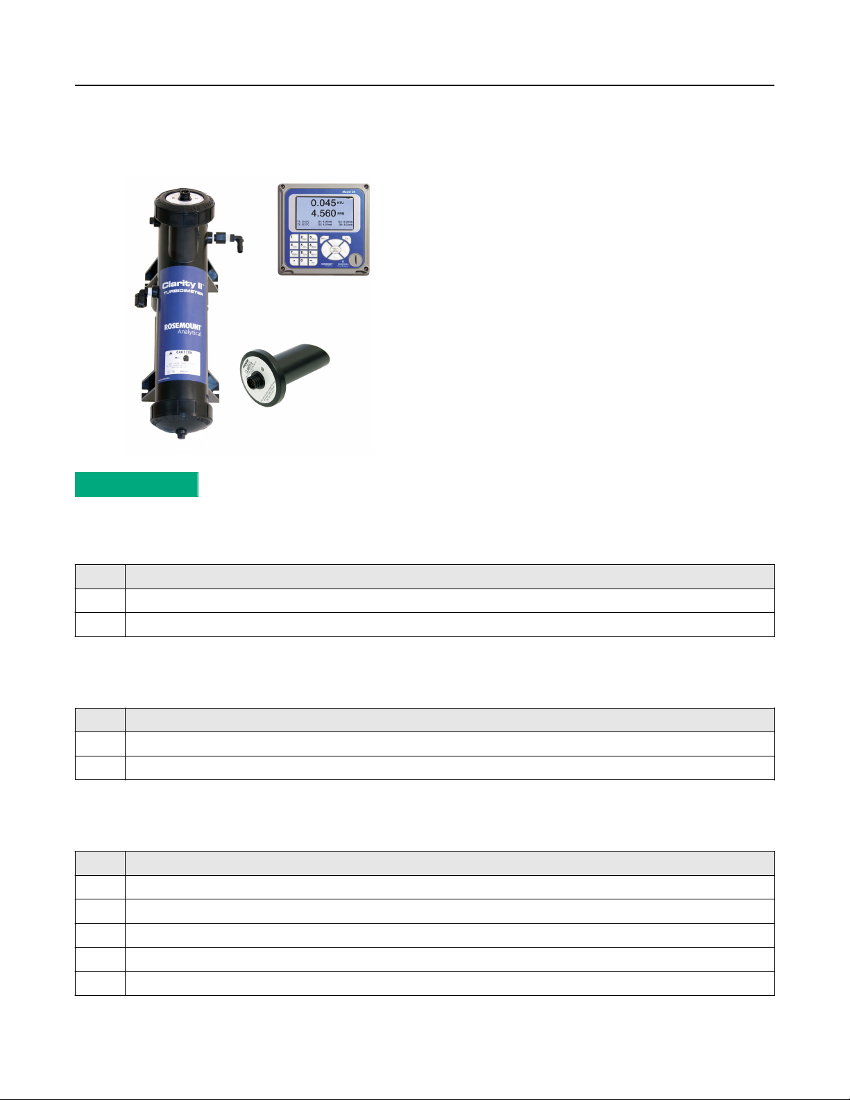
Rosemount™ Clarity II T56 Turbidimeter
Turbidity Measurement System
January 2021
■
Complete system includes single or dual input transmitter, sensor(s), and debubbler assembly
■
Resolution 0.001 NTU
■
Easy to use transmitter with four analog outputs and four programmable alarm relays
■
Intuitive, user-friendly menu in nine languages makes setup and calibration easy
■
HART® digital communications standard
■
Data and event logger stores thirty days of data for output on USB 2.0 memory stick
Page 2

Rosemount T56 January 2021
Features and applications
The Rosemount T56 Turbidimeter is intended for the determination of turbidity in water. Low stray light, high stability, efficient
bubble rejection, and a display resolution of 0.001 NTU make the turbidimeter ideal for monitoring the turbidity of filtered drinking
water. You can also use the turbidimeter in applications other than drinking water treatment. Examples are monitoring wastewater
discharges, condensate returns, and clarifiers.
The turbidimeter consists of a transmitter, which accepts either one or two sensors, the sensors themselves, and a debubbler/
measuring chamber and cable for each sensor. The cable plugs into the sensor and the transmitter, making setup fast and easy.
Sensors can be located as far as 50 ft. (15.2 m) away from the transmitter.
■
ISO 7027 sensors use a near infrared light-emitting diode (LED).
■
The turbidimeter incorporates the popular and easy to use Rosemount 56 Transmitter.
■
4-20 mA analog outputs are fully scalable.
■
Every unit includes four alarm relays with interval timer functions. Alarms are fully programmable for high/low logic and dead
band.
The turbidimeter is available in an optional configuration in which the transmitter, sensor(s), and debubbling flow cell(s) are
mounted on a single back plate. The sensor cables are pre-wired to the transmitter, so setup is exceptionally fast and easy. Simply
mount the turbidimeter on a wall, bring in power and sample, and provide a drain. To order this option, consult the factory.
Contents
Features and applications.................................................................................................................................................................. 2
Ordering information........................................................................................................................................................................ 3
Specifications.................................................................................................................................................................................... 5
Dimensional drawings..................................................................................................................................................................... 10
Accessories......................................................................................................................................................................................13
Calibration standards.......................................................................................................................................................................13
2 Emerson.com/Rosemount
Page 3
January 2021 Rosemount T56
Ordering information
■
The Rosemount Clarity II Turbidimeter is a complete system
for the determination of turbidity in water.
■
It consists of an analyzer and one or two sensors with a
debubbler/measuring chamber assembly and a cable for
each sensor.
■
Four alarm relays are standard.
■
A calibration cup is available as an option.
■
Because a sensor cannot be calibrated without a calibration
cup, order at least one cup.
■
Calibration standard (formazin or polymer spheres) must be
ordered as a separate item
VIEW PRODUCT >
Sensor
Code
02 ISO sensor
41 Two ISO sensors
Description
Measuring chamber
Code
10 Debubbler flow chamber (required -02)
60 Two debubbler flow chambers (required -41)
Description
Sensor cable
Code
Description
20 20-ft. (6.1 m) cable
21 50-ft. (15.2 m) cable
50 Two 20-ft. (6.1 m) cables
51 Two 50 ft. (15.2 m) cables
23 One 20-ft. (6.1 m) cable, one 50-ft. (15.2 m) cable
Rosemount T56 3
Page 4

Rosemount T56 January 2021
Instrument
Code Description
30 Single input/HART® turbidity instrument (56-03-27-38-HT) (required -02)
31 Dual input/HART turbidity instrument (56-03-27-37-HT) (required -41)
Calibration cup
Code Description
71 Calibration cup (recommended for calibration)
4 Emerson.com/Rosemount
Page 5

January 2021 Rosemount T56
Specifications
Note
Specifications subject to change without notice.
General specifications
Enclosure
Dimensions
Conduit openings
Display
Measurement character
height
Security code
Languages
Polycarbonate. Type 4X/CSA 4X IP66
6.2 x 6.2 x 5.2-in. (157 x 157 x 132 mm)
Accepts ½-in. or PG 13.5 conduit fittings.
Large 3.76 x 2.2-in. (95.3 x 55.9 mm) high resolution color LCD display for large process variables
and user-definable display of diagnostic parameters. Back-lighting is user adjustable. You can
customize the main display to meet your requirements.
0.5-in. (13 mm)
Three-digit code prevents accidental or unauthorized changes in instrument settings and
calibration.
■
English
■
French
■
German
■
Italian
■
Spanish
■
Portuguese
■
Chinese
■
Russian
■
Polish
Units
Display resolution:
turbidity
Display resolution: TSS
Calibration methods
Ambient temperature and
humidity
Turbidity
■
NTU
■
FTU
■
FNU
Total suspended solids
■
mg/L
■
ppm
■
No units
Four digits; decimal point moves from x.xxx to xxx.x
Four digits; decimal point moves from x.xxx to xxx.x
User-prepared standard, commercially prepared standard, or grab sample. For total suspended
solids, you must provide a linear calibration equation.
32 to 131 °F (0 to 55 °C)
Rosemount T56 5
Page 6

Rosemount T56 January 2021
Altitude
Storage temperature
Real time clock backup
Power
Inputs
Outputs
Output dampening
Current output accuracy
Alarms
Terminal connections
rating
RFI/EMI
LVD
Relays
For use up to 6562 ft. (2000 m).
-4 to 140 °F (-20 to 60 °C)
24 hours
85 to 265 Vac, 47.5 to 65.0 Hz, 20 W min. input power
Equipment protected by double insulation.
One or two isolated sensor inputs.
Four 4-20 mA or 0-20 mA isolated current outputs. Fully scalable. Maximum load: 550 ohm.
Output 1 has superimposed HART® signal.
0-999 seconds
±0.05 mA at 77 °F (25 °C)
Four process alarm relays for turbidity or temperature. You can also program relays for timer, TPC,
or fault alarm operation instead of as process alarms. You can configure each relay independently.
Alarm logic (high or low activation) and deadband are user-programmable.
Power connector (3 leads): 24-12 AWG wire size.
Signal board terminal blocks: 26-16 AWG wire size.
Current output connectors (2 leads): 24-16 AWG wire size.
Alarm relay terminal blocks: 24-12 AWG wire size.
EN 61326
EN-61010-1
Form C, single pole, double throw, epoxy sealed
Table 1: Maximum Relay Current
Supply voltage Resistive
28 Vdc 5.0 A 5.0 A
115 Vac 5.0 A 5.0 A
230 Vac 5.0 A 5.0 A
Field wiring terminals
Removable terminal blocks for power, analog outputs, and sensors.
Transmitter hazardous location approvals
CSA approvals
Class 1, Division 2, Groups A, B, C, and D
Class II, Division 2, Groups E, F, and G
Class III T4A Tamb = 50 °C
Evaluated to the ANS/UL standards. The C and US indicators adjacent to the CSA mark signify that the product
has been evaluated to the applicable CSA and ANSI/UL standards for use in Canada and the US respectively.
FM approvals
Class I, Division 2, Groups A, B, C, and D
Class II, Division 2, Groups E, F, and G
T4 Tamb = -10 °C to 60 °C
6 Emerson.com/Rosemount
Page 7

January 2021 Rosemount T56
Sensor
Method
LED life
Wetted materials
Accuracy after calibration at
20.0 NTU
Cable
Maximum pressure
Temperature
Sensor body rating
ISO 7027 (using 860 nm LED source).
Three years (ISO 7027)
Delrin1, glass, EPDM
0 - 1 NTU: ±2 percent of reading or ±0.015 NTU, whichever is greater.
0 - 20 NTU: ±2 percent of reading
Note
The sensor can measure turbidity values of 2-200 NTU, but frequent cleaning may be required
to maintain turbidity measurements.
20 ft. (6.1 m) or 50 ft (15.2 m). Connector is IP65.
30 psig (308 kPa abs)
40 to 95 °F (5 to 35 °C)
IP65 when cable is connected.
Debubbler and flow chamber
Dimensions
Wetted materials
Inlet
Drain
Sample temperature
Minimum inlet pressure
Maximum inlet pressure
Recommended sample flow
18.1 x 4.1-in. (460 mm x 104 mm) diagram (approximately)
ABS, EPDM, Delrin®, polypropylene, nylon
Compression fitting accepts ¼-in. OD tubing; fitting can be removed to provide ¼-in. female
national pipe thread (FNPT).
Barbed fitting accepts ⅜-in. ID tubing; fitting can be removed to provide ¼-in. FNPT. Must drain to
atmosphere.
40 to 95 °F (5 to 35 °C)
3.5 psig
3.5 psig will provide about 0.01 oz./min (250 mL/min) sample flow.
30 psig. Do not block drain tube.
0.01 to 0.03 oz./min (250 to 750 mL/min)
Miscellaneous
Weight/shipping weight
Note
Rounded to the nearest lb. or 0.5 kg.
Sensor
Transmitter
Debubbler
Rosemount T56 7
1 lb./2 lb. (0.5 kg/1.0 kg)
2 lb./3 lb. (1.0 kg/1.5 kg)
3 lb./4 lb. (1.5 kg/2.0 kg)
Page 8

Rosemount T56
January 2021
Sample engineering specification for Rosemount Clarity II Turbidimeter
Turbidimeter
1. The turbidimeter shall be a complete system consisting of sensor, analyzer, flow chamber/debubbler, and interconnecting
cable. The transmitter shall accept input from either one or two sensors.
2. The turbidimeter shall have the following accuracy (after calibration with 20.0 NTU standard): a) 0 5 NTU: ±2 percent of
reading or 0.015 NTU, whichever is greater; b) 0 20 NTU: ±2 percent of reading.
3. The response time at 4 gph (250 mL/min) to 90 percent of final value following a step change shall be 4.5 minutes.
4. The sensor shall be constructed of corrosion-resistant Delrin® with glass lamp and detector windows.
5. Light-emitting diode (LED) life (ISO-compliant sensor) shall be at least three years.
6. The sensor shall include advanced diagnostics, which will continuously measure the lamp intensity and automatically adjust
the lamp output thereby maintaining the correct lamp intensity, correct for lamp drifting and aging, and allow for longer
sensor operation with reduced calibration requirements.
7. The measuring chamber shall be constructed of ABS and Delrin. A bubble removal section shall allow entrained bubbles to
escape from the sample before measurement.
8. The turbidimeter shall accept a sample stream having temperature between 40 and 95 °F (5 and 35 °C) with inlet pressure as
high as 30 psig with drain to open atmosphere.
9. The sample chamber shall include a two-stage removal of entrained bubbles and outgassed bubbles to prevent erroneous
turbidity readings.
Transmitter
1. The transmitter shall have a large back-lit display.
2. The transmitter shall measure turbidity in the range 0 to 5 NTU with a display resolution of 0.001 NTU. Display units shall be
user selectable among NTU, FTU, and FNU.
3. The transmitter shall display menu items and prompts in a language selected by the user. The languages shall be English,
German, French, Spanish, Italian, Portuguese and Chinese.
4. The transmitter shall allow direct button key access to comprehensive diagnostics from the main display screen.
5. The transmitter shall allow the user to customize the readouts on the main display screen.
6. A user-defined security code shall be available to protect against accidental or unauthorized changes to program settings
and calibration.
7. Bubble rejection, signal averaging, and output hold features shall be available.
8. The single input and dual input transmitters shall have two current outputs, and the dual input transmitter shall have dual
output. User-selectable 0-20 mA and 4-20 mA outputs shall be provided. Outputs shall be isolated with 550 ohm maximum
load.
9. Four relays are standard. All alarms shall be fully programmable for high/low logic and deadband. All alarms can be
configurable as a fault alarms. Interval timers can be enabled.
10. Environmental limits for the transmitter shall be 32 to 122 °F (0 to 50 °C) and 10 to 90 percent relative humidity.
11. Interconnecting cable shall plug into the sensor and analyzer. Integral cable or cable with flying leads shall not be permitted.
Maximum cable length shall be 50 ft. (15.2 m).
12. Field wiring terminal blocks for power, sensor and analog outputs shall be removable for ease of wiring.
13. The transmitter enclosure shall be Type 4X/CSA 4 (IP65), and the power requirements shall be in the range of 85 – 265 Vac,
47.5 – 65.0 Hz or 2030 Vdc.
14. If so programmed, the transmitter shall convert measured turbidity to a total suspended solids (TSS) reading using a linear
equation entered by the user. Units for TSS shall be user selectable among ppm, mg/L, or no units.
15. HART® digital communications shall be available as an ordering option.
8 Emerson.com/Rosemount
Page 9

January 2021 Rosemount T56
Calibration
1. The transmitter shall offer three methods of calibration: two-point slope calibration with deionized water and diluted
formazin, standard calibration to a commercial standard, and calibration to a grab sample measured on a reference
turbidimeter.
2. A maximum of 300 mL of calibration standard shall be required to calibrate the transmitter.
3. Accessories, unless noted: Calibration cup, cal kits with formazin.
The Rosemount Clarity II Turbidimeter shall include a one year factory warranty.
The turbidimeter shall be Rosemount T56 Clarity II Turbidimeter or approved equal.
Rosemount T56 9
Page 10

Rosemount T56
Dimensional drawings
Figure 1: Panel Mount Dimensions
Front view Side view
January 2021
Bottom view
A. Panel mount gasket
B. Panel supplied by others maximum thickness .375-in.(9.52mm)
C. 4X mounting brackets and screws provided with instrument
D. Conduit openings
E. Maximum radius
Note
The front panel is hinged at the bottom. The panel swings down for easy access to the wiring locations.
10 Emerson.com/Rosemount
Page 11

January 2021
Figure 2: Pipe/Wall Mount Dimensions (Mounting bracket PN:2382000)
Wall/surface mount
Pipe mount
Rosemount T56
A. Front view
B. 4x cover screw
C. Side view
D. Bottom view
E. Front panel
F. Panel and pipe mount enclosure
G. Conduit openings
H. 2-in. pipe mount bracket
I. 2x set u-bolts for 2-in. pipe in kit PN 23820-00
J. Side view
K. 2-in. pipe supplied by customer
Note
The front panel is hinged at the bottom. The panel swings down for easy access to the wiring locations.
Rosemount T56 11
Page 12

Rosemount T56
Figure 3: Sensor
A. O-ring PN 9550145
B. Light source
C. Detector
January 2021
Figure 4: Debubbler and Flow Chamber
A. Inlet
B. Outlet
C. Sensor port
12 Emerson.com/Rosemount
Page 13

January 2021 Rosemount T56
Accessories
Product number Description Weight Shipping WT
23554-00 Cable gland kit for Model 54e, XMT, 1055, or 1056.
Quantity 5
23820-00 Pipe mounting kit, includes u-bolts, mounting
bracket, nuts, washers, and screws
23820-01 2-in. pipe mounting bracket, stainless steel 2 lb. (1.0 kg) 4 lb. (2.0 kg)
24101-00 Calibration cup 1 lb. (0.5 kg) 2 lb. (1.0 kg)
24138-00 Sensor cable, turbidity, 3 ft. 1 lb. (0.5 kg) 2 lb. (1.0 kg)
8-0108-0002-EPA Replacement sensor, USEPA-compliant 1 lb. (0.5 kg) 2 lb. (1.0 kg)
8-0108-0003-ISO Replacement sensor, ISO-compliant 1 lb. (0.5 kg) 2 lb. (1.0 kg)
24103-00 Flowmeter kit, includes valved rotameter and fittings 1 lb. (0.5 kg) 2 lb. (1.0 kg)
9240048-00 Tag, stainless steel, specify markings .1 lb. (0.05 kg) 1 lb. (0.5 kg)
9550145 O-ring for sensor, external, fits molded debubbler .1 lb. (0.05 kg) 1 lb. (0.5 kg)
24170-00 Molded debubbler with integral flow chamber 3 lb. (1.5 kg) 4 lb. (2.0 kg)
9550322 O-ring for upper and lower debubbler caps .1 lb. (0.05 kg) 1 lb. (0.5 kg)
1-901-0010-ISO Replacement lamp board kit, ISO .1 lb. (0.05 kg) 1 lb. (0.5 kg)
1 lb. (0.5 kg) 2 lb. (1.0 kg)
2 lb. (1.0 kg) 4 lb. (2.0 kg)
Calibration standards
Product number
060-761855 Calibration kit (includes 4000 NTU formazin standard, pipet,
905-761854 Formazin standard, 4000 NTU, 125 mL 1 lb. (0.5 kg) 1 lb. (0.5 kg)
Desciption Weight Shipping WT
1 lb. (0.5 kg) 2 lb. (1.0 kg)
pipet bulb, and volumetric flask)
Rosemount T56 13
Page 14

Rosemount T56 January 2021
14 Emerson.com/Rosemount
Page 15

January 2021 Rosemount T56
Rosemount T56 15
Page 16

00813-0100-3565
Rev. AB
January 2021
EMERSON AUTOMATION SOLUTIONS
6021 Innovation Blvd
Shakopee, MN 55379, USA
+1 800 999 9307 or +1 952 906 8888
F +1 952 949 7001
RMTNA.RCCPO@Emerson.com
EUROPE
Emerson Automation Solutions
Neuhofstrasse 19a P.O. Box 1046
CH-6340 Baar
Switzerland
T + 41 (0) 41 768 6111
F + 41 (0) 41 768 6300
RMTNA.RCCPO@Emerson.com
Linkedin.com/company/Emerson-Automation-Solutions
twitter.com/rosemount_news
Facebook.com/Rosemount
youtube.com/RosemountMeasurement
NORTH AMERICA
Emerson Automation Solutions
8200 Market Blvd
Chanhassen, MN 55317
Toll Free +1 800 999 9307
F +1 952 949 7001
RMTNA.RCCPO@Emerson.com
MIDDLE EAST AND AFRICA
Emerson Automation Solutions
Emerson FZE
Jebel Ali Free Zone
Dubai, United Arab Emirates, P.O. Box 17033
T +971 4 811 8100
F +971 4 886 5465
RMTNA.RCCPO@Emerson.com
©
2021 Emerson. All rights reserved.
The Emerson logo is a trademark and service mark of Emerson Electric Co. Rosemount is a
mark of one of the Emerson family of companies. All other marks are the property of their
respective owners.
ASIA-PACIFIC
Emerson Automation Solutions
1 Pandan Crescent
Singapore 128461
Singapore
T +65 777 8211
F +65 777 0947
RMTNA.RCCPO@Emerson.com
 Loading...