

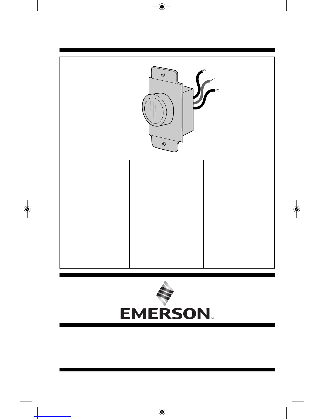
Emerson SW93, SW95, SW96 Owner's Manual
CAUTION: Read all instructions carefully before installation.
Save this Owner's Manual for future reference.
Ceiling Fan Wall Control
Owner's Manual
Model No.
SW93
DUAL FAN
CONTROL
•
Maximum
3.0 AMP, 120 VAC,
60 HZ, Single-Pole
•
3-Speed Fan Motor
Control
Model No.
SW95
SINGLE FAN
CONTROL
•
Maximum
1.25 AMP, 120 VAC,
60 HZ, Single-Pole
•
4-Speed Fan Motor
Control
Model No.
SW96
3-4 FAN
CONTROL
•
Maximum
5.0 AMP, 120 VAC,
60 HZ, Single-Pole
•
4-Speed Fan Motor
Control
Part No. F40BP74990000 Form No. BP7499
Revision: 141110 U.L. Model No.: SW93/SW95/SW96
BP7499 SW93 SW95 SW96.qxp_Layout 1 12/1/14 2:39 PM Page 1
2
U.L. Model No.: SW93/SW95/SW96
READ AND SAVE THESE INSTRUCTIONS
Table of Contents
Safety Instructions
Section Page
Safety Instructions . . . . . . . . . . . . 2-3
1. Unpacking Instructions . . . . . . . . 3
2. General Information . . . . . . . . . . 4
3. Wall Control Instructions . . . . 4-8
Section Page
4. Wall Control Wiring Diagrams . . 9
5. Operation . . . . . . . . . . . . . . . . . 10
Limited Warranty . . . . . . . . . . . . . . 11
Additional Safety
Instructions for Installation
1.To avoid possible electrical
shock, be sure electricity is
turned off at the main fuse or
circuit breaker box before wiring.
2.Make certain no bare wires are
exposed outside the wire
connectors.
3.All wiring must conform to
National and Local Electrical
Codes.
4.Follow the recommended
instructions for the proper
method of wiring your new Wall
Control. If you feel you do not
have enough electrical wiring
knowledge or experience, have
your Wall Control installed by a
licensed electrician. Any
electrical work not described in
this manual should be performed
by a licensed electrician.
TO REDUCE THE RISK OF FIRE,
ELECTRICAL SHOCK, OR INJURY
TO PERSONS, OBSERVE THE
FOLLOWING:
a.Read your Owner’s Manual
carefully before installing the
Wall Control. Retain Owner’s
Manual for future reference.
b.Before servicing or cleaning
the ceiling fan, switch power
off at service panel and lock
service panel disconnecting
means to prevent power from
being switched on accidentally. When the service disconnecting means cannot be
locked, securely fasten a
warning device such as a tag,
to the service panel.
!
WARNING
BP7499 SW93 SW95 SW96.qxp_Layout 1 12/1/14 2:39 PM Page 2
3
emersonfans.com
Please contact 1-800-654-3545 for further assistance
U.L. Model No.: SW93/SW95/SW96
Safety Instructions Continued
1. Unpacking Instructions
WARNING: Use of this control
with some ceiling fans could result
in fire, shock and serious personal
injury. Use this speed control only
with Emerson CF series ceiling
fans that are suitable for use with
solid-state controls.
WARNING: This product is
designed for use with only those
ceiling fans designated specifically
for use with this product by
Emerson Electric Co. Substitution
of parts or accessories not
designated for use with this
product by Emerson Electric Co.
could result in personal injury or
property damage.
Do not install or use fan if any part is
damaged or missing. Call Toll-Free
for replacement parts:
1-800-654-3545
!
WARNING
This product is designed to use only
those parts supplied with this
product and/or any accessories
designated specifically for use with
this product by Emerson Electric
Co. Substitution of parts or
accessories not designated for use
with this product by Emerson
Electric Co. could result in personal
injury or property damage.
!
WARNING
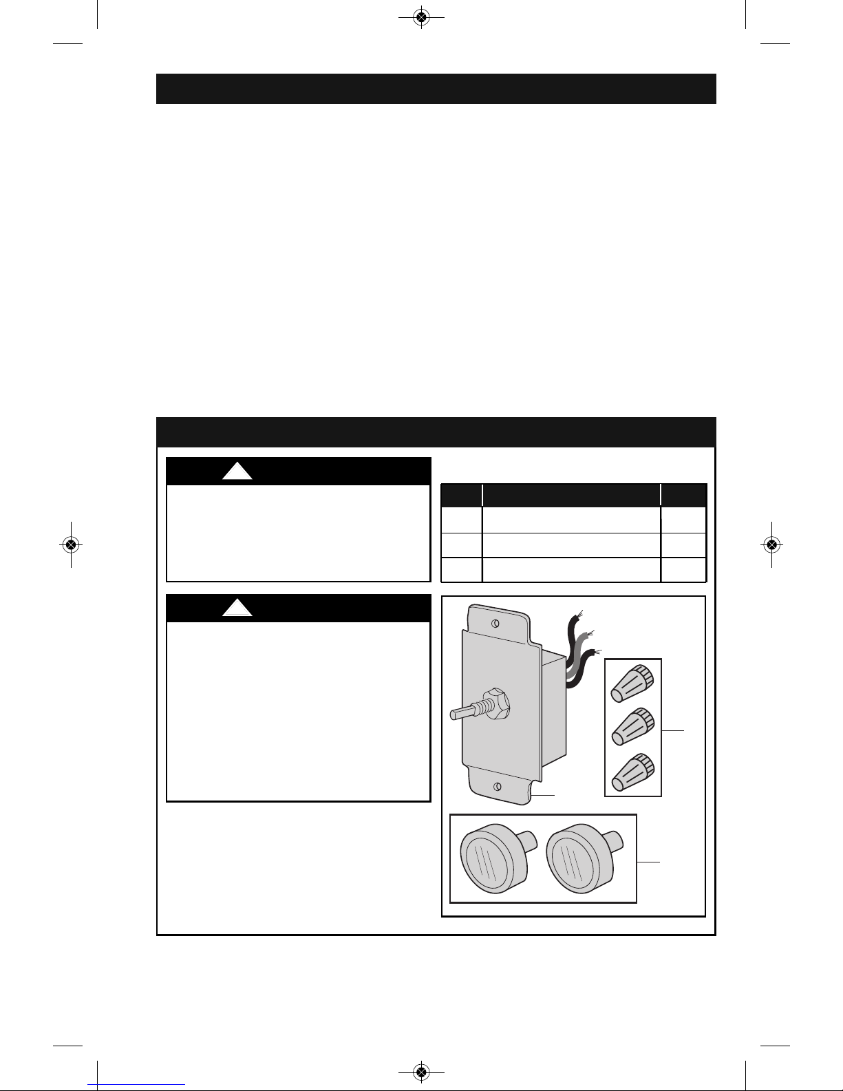
A
C
B
PACKAGE CONTENTS
Part Description Qty.
A Wall Control Switch 1
B Knob 2
C Wire Connector 3
Tools Needed for Assembly
One Phillips head screwdriver
One blade screwdriver
One wire stripper
One stepladder
BP7499 SW93 SW95 SW96.qxp_Layout 1 12/1/14 2:39 PM Page 3
4
U.L. Model No.: SW93/SW95/SW96
2. General Information
The SW93 & SW96 Wall Controls
are designed to operate multiple
ceiling fans, and Not any
accessory light kits.
The SW95 Wall Control is
designed to operate only one
ceiling fan, and Not an accessory
light kit.
The SW93 / SW95 / SW96 Wall
Controls do not require a receiver.
The SW93 Wall Control is rated for
3.0 Amp, 120 VAC, 60 HZ full load.
The SW95 Wall Control is rated for
1.25 Amp, 120 VAC, 60 HZ full
load.
The SW96 Wall Control is rated for
5.0 Amp, 120 VAC, HZ full load.
To avoid erratic speeds and
possible damage to your ceiling
fan, use the Wall Control only with
fans pull chain switches set to
their high speed settings.
All ceiling fans must be
completely installed before
installation of the Wall Control.
Your new Wall Control will require
a grounded electrical supply line
of 120 volts AC, 60 HZ circuit.
3. Wall Control Installation
Installation of Wall Control
replacing an Existing Wall
Control:
3.1
Disconnect electrical power to the
branch circuit at the circuit breaker
or fuse box before attempting to
install the ceiling fan mounting plate
on the outlet box.
NOTE: The ceiling fan must be set
at the highest speed setting
before installation of the Wall
Control.
Turning off wall switch is not
sufficient. To avoid possible
electrical shock, be sure electricity
is turned off at the main fuse box
before wiring. All wiring must be in
accordance with National and Local
codes and the ceiling fan must be
properly grounded as a precaution
against possible electrical shock.
!
WARNING
BP7499 SW93 SW95 SW96.qxp_Layout 1 12/1/14 2:39 PM Page 4
5
emersonfans.com
Please contact 1-800-654-3545 for further assistance
U.L. Model No.: SW93/SW95/SW96
3. Wall Control Installation (Continued)
3.2
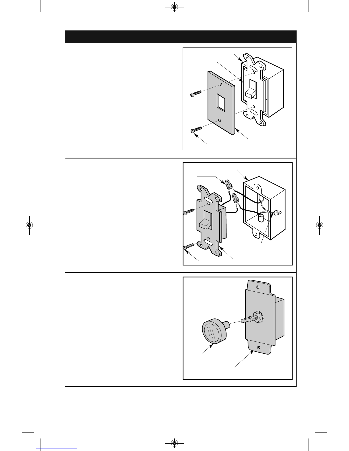
Remove the faceplate and the two 632 screws from the existing wall
switch (retain faceplate and screws
for future use).
FACEPLATE
WALL OUTLET BOX
SWITCH
6-3 SCREWS (2)
3.3
Pull existing wall switch out from the
wall outlet box.
3.4
Disconnect the existing wall switch
wires from the wires in the outlet box
by removing the the two wire
connectors (discard connectors).
NEUTRAL
LEAD WIRES
WALL OUTLET BOX
EXISTING WALL SWITCH
SCREWS (2)
WIRE
CONNECTOR (2)
3.5
Set the new Wall Control in the OFF
position (full counter-clockwise).
3.6
Pull the knob of the Wall Control
(retain for future use).
WALL CONTROL
KNOB
BP7499 SW93 SW95 SW96.qxp_Layout 1 12/1/14 2:39 PM Page 5

6
U.L. Model No.: SW93/SW95/SW96
3. Wall Control Installation (Continued)
3.7
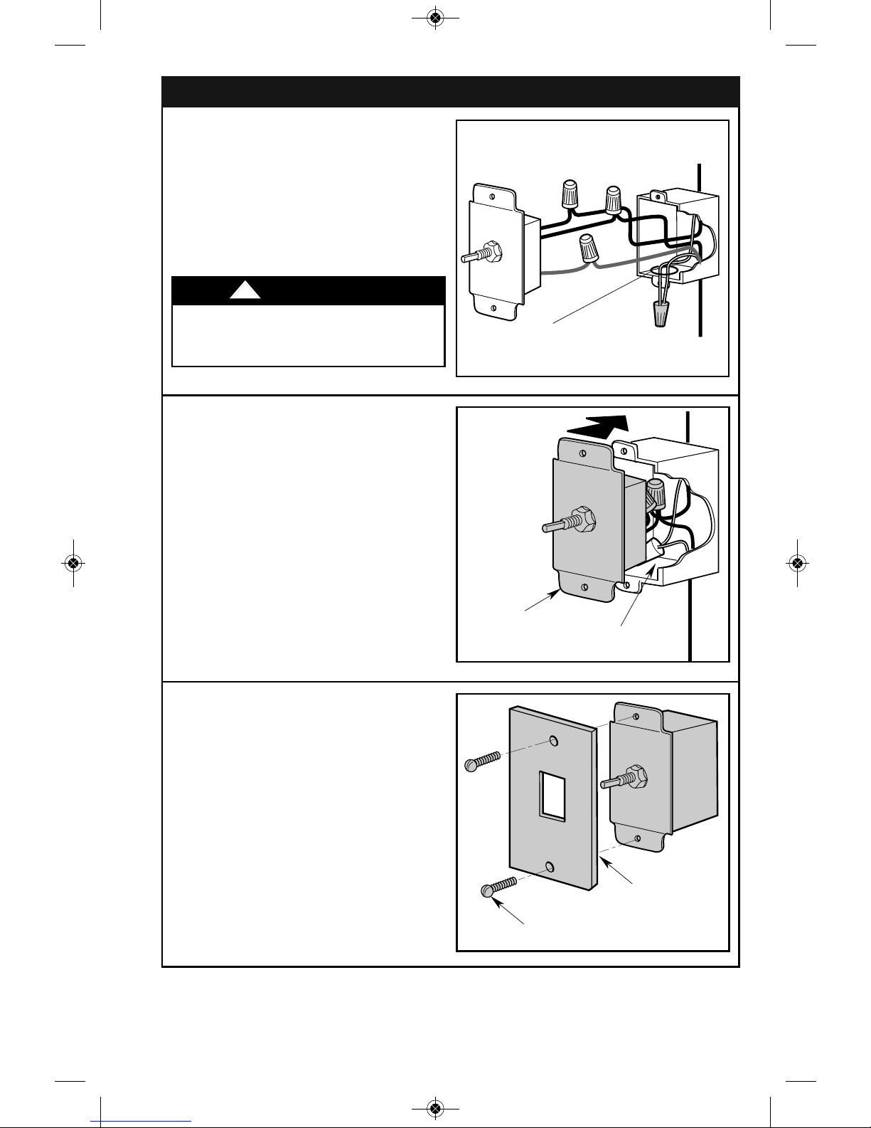
Connect the Wall Control BLACK
wire to the Fan/Motor Lead (BLACK
or RED) wire using a new wire
connector (supplied).
NOTE: Use only the wire
connectors supplied with the new
wall control to secure electrical
connections.
TO 120VAC
SOURCE HOT
FAN/ MOTO R
BLACK OR RED
WIRE
W
ALL CONTROL
B
LACK WIRE
TO FAN
MOTOR LOAD
WALL CONTROL
WIRE
CONNECTOR
3.8
Connect the Wall Control BLACK
wire to the 120 VAC source hot
BLACK wire using a new wire
connector (supplied).
TO 120VAC
SOURCE HOT
WALL CONTROL
BLACK WIRE
TO FAN
MOTOR LOAD
WALL
CONTROL
120 VAC HOT
BLACK WIRE
WIRE CONNECTOR
3.9
Securely connect the GREEN
ground wire from the Wall Control to
the supply ground wire (bare or
green).
WIRE
CONNECTOR
SUPPLY
GREEN
GROUND
WIRE
WALL CONTROL
GREEN
GROUND WIRE
Check to see that all wire
connections are tight, including
ground, and that no bare wire is
visible at the wire connectors,
except for ground.
!
WARNING
BP7499 SW93 SW95 SW96.qxp_Layout 1 12/1/14 2:39 PM Page 6
Do not connect any neutral (WHITE)
wire to this control. Incorrect wiring
WILL damage this control.
!
WARNING
7
emersonfans.com
Please contact 1-800-654-3545 for further assistance
U.L. Model No.: SW93/SW95/SW96
3. Wall Control Installation (Continued)
3.10
NOTE: The WHITE neutral wires
inside the electrical box must be
connected together for proper
operation of the wall control.
NEVER connect the WHITE
neutral wires to the Wall Control.
TO 120VAC
SOURCE HOT
TO FAN
MOTOR LOAD
DO NOT CONNECT ANY WIRES
FROM WALL CONTROL TO THESE
WHITE NEUTRAL WIRES
3.11
Carefully tuck all wires and wire
connectors into the outlet box and
position the Wall Control onto the
outlet box.
WALL
CONTROL
WIRES TUCKED
INTO OUTLET BOX
POSITION THE
WALL CONTROL
INTO THE
OUTLET BOX
3.12
Place the previously removed
faceplate onto the Wall Control.
3.13
Assemble the faceplate to the Wall
Control using the two previously
removed 6-32 screws.
PREVIOUSLY
REMOVED
FACEPLATE
PREVIOUSLY REMOVED
6-32 SCREWS (2)
BP7499 SW93 SW95 SW96.qxp_Layout 1 12/1/14 2:39 PM Page 7

3. Wall Control Installation (Continued)
8
U.L. Model No.: SW93/SW95/SW96
3.14
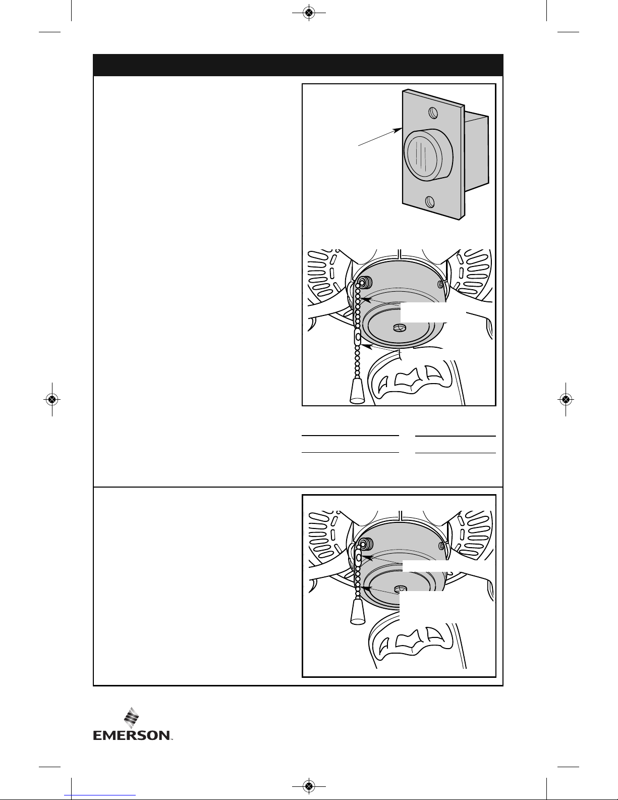
The Wall Control is supplied with a
white and almond knob. Select the
knob that matches the color of
existing faceplate.
3.15
Press knob onto the shaft of the Wall
Control.
3.16
Rotate knob counter-clockwise to
the full OFFposition.
3.17
To Complete Installation: Restore
power at the main fuse box or circuit
breaker panel.
KNOB
WALL
CONTROL
BP7499 SW93 SW95 SW96.qxp_Layout 1 12/1/14 2:39 PM Page 8

9
emersonfans.com
Please contact 1-800-654-3545 for further assistance
U.L. Model No.: SW93/SW95/SW96
4. Wall Control Wiring Diagrams
4.1: SW93 Dual Fan Wall Control
TO FAN MOTOR LOAD
TO 120VAC
SOURCE HOT
SW93 DUAL FAN
WALL CONTROL
MOTOR LOAD
BLACK
BLACK
BLACK or RED
BLACK
GREEN
GREEN
4.2: SW95 Single Fan Wall Control
TO NEUTRAL
TO FAN MOTOR LOAD
TO 120VAC
SOURCE HOT
SW95 SINGLE FAN
WALL CONTROL
BLACK
BLACK
BLACK or RED
BLACK
GREEN
GREEN
4.3: SW96 3 or 4 Fan Wall Control (5 Amp Max.)
TO
NEUTRAL
TO FAN MOTOR LOAD
TO 120VAC
SOURCE HOT
SW96 3 or 4 FAN
WALL CONTROL
BLACK
BLACK
BLACK or RED
BLACK
GREEN
GREEN
MOTOR
LOAD
MOTOR
LOAD
BP7499 SW93 SW95 SW96.qxp_Layout 1 12/1/14 2:39 PM Page 9
10
U.L. Model No.: SW93/SW95/SW96
5. Operation
CAUTION
For fans equipped with built-in
variable speed devices: These
devices must be set at their
MAXIMUM SPEED for proper
operation. Adjustments to their
setting must only be made with
this fan control in the OFF
position. Changing or switching
these settings while the fan
control is in operation could
damage the control.
NOTE: Fan control knob turns fan
on at maximum speed to assist
motor start-up. Fan speed
decreases with clockwise rotation.
5.1
Set the fans on their HIGH speed
pull chain settings. Then use your
speed control to select any of the
speeds, plus OFF.
NOTE: Fully counter-clockwise is
OFF. The three or four fan speeds
are selected by rotating the knob
one position at a time clockwise.
CHAIN COUPLER
3-SPEED SWITCH
PULL CHAIN
WALL
CONTROL
5.2
IMPORTANT
Always have the fan switch set to
HIGH speed before using the wall
control. To avoid accidental pull
chain use, shorten chain by
cutting it 1-inch below switch
body.
CHAIN COUPLER
SHORTENED
3-SPEED SWITCH
PULL CHAIN
1st Pull—HIGH
2nd Pull—Medium
3rd Pull—Low
4th Pull—OFF
BP7499 SW93 SW95 SW96.qxp_Layout 1 12/1/14 2:39 PM Page 10

11
emersonfans.com
Please contact 1-800-654-3545 for further assistance
U.L. Model No.: SW93/SW95/SW96
What The Warranty Covers:
All products covered by this Owner’s Manual are warranted against all defects in workmanship
and materials. You must be the original purchaser or user of the product to be covered.
What The Period Of Coverage Is:
All components are covered by this warranty for one year from the date you purchased your fan
control. ANY IMPLIED WARRANTY OF MERCHANTABILITY OR FITNESS FOR A PARTICULAR
PURPOSE, MADE WITH RESPECT TO COMPONENTS AND ACCESSORIES IS ALSO LIMITED TO
ONE YEAR.
What Will Emerson Electric Co. Do To Correct Problems:
Emerson Electric Co. will replace a defective Emerson Fan Control at no charge to you. We will
ship the repaired product or replacement to you at no charge, but you are responsible for all costs
or removal, reinstallation and shipping of the product to Emerson.
How Can You Get Service:
YOU MUST HAVE PROOF OF YOUR PURCHASE OF THE FAN CONTROL TO OBTAIN LIMITED
WARRANTY SERVICE. KEEP YOUR RECEIPT OR OTHER PROOF OF PURCHASE. You can return
the product to our factory or to your nearest authorized service center.
• To return the product to the factory, obtain a return authorization and service identification tag
by writing to Air Comfort Products, Division of Emerson Electric Co., 8100 W. Florissant Ave.,
St. Louis, MO 63136. Include all model numbers shown on the product with your request.
• To return the product to an authorized service center, call 1-800-654-3545 for the address of
the nearest authorized service center.
You will be responsible for all insurance, freight or other transportation charges to our factory or
authorized service center. Your Emerson Fan Control should be properly packed to avoid damage
in transit since we will not be responsible for any such damage.
What Is Not Covered:
This warranty also does not cover any defects, malfunctions or failures caused by:
• Repairs by persons not authorized by Emerson Electric Co.,
• Use of parts or accessories not authorized by Emerson Electric Co.,
• Mishandling, improper installation, modifications or damage to your wall control while in your
possession, or
• Unreasonable use, misuse, abuse, including failing to do reasonable and necessary
maintenance, and normal wear and tear.
Additionally, this warranty and any implied warranty of merchantability or fitness for a particular
purpose are voided when:
• The original purchaser or user ceases to own the product, or
• The ceiling fan is moved from its original point of installation.
This warranty is only valid within the 50 states of the United States, the District of Columbia and
Canada. No other written or oral warranties apply, and no employee, agent, dealer or other person
is authorized to give any warranties on behalf of Emerson Electric Co.
REPAIR, REPLACEMENT OR A REFUND ARE THE EXCLUSIVE REMEDIES AVAILABLE UNDER
THIS WARRANTY AND EMERSON IS NOT RESPONSIBLE FOR DAMAGES OF ANY KIND,
INCLUDING INCIDENTAL AND CONSEQUENTIAL DAMAGES. Incidental damages include but are
not limited to such damages as loss of time and loss of use. Consequential damages include but
are not limited to the cost of repairing or replacing other property which was damaged if this
product does not work properly.
How State Law Relates To The Warranty:
Some states do not allow the exclusion or limitation of incidental or consequential damages so
the above exclusion or limitation may not apply to you. This warranty gives you specific legal
rights, and you may also have other rights which vary from state to state.
Limited Warranty
BP7499 SW93 SW95 SW96.qxp_Layout 1 12/1/14 2:39 PM Page 11
 Loading...