

Page 1
SYSTEM OVERVIEW
Description: +24V DC @ up to 4000 amperes Power System.
This power system is designed to power a load while charging a negative grounded
battery. This power system is capable of operating in a batteryless installation or off
battery for maintenance purposes. The power system is designed for operation with the
negative output grounded.
The N
containing rectifiers (PCUs), converters, intelligent control, metering, monitoring, and
distribution. This power system consists of the following components.
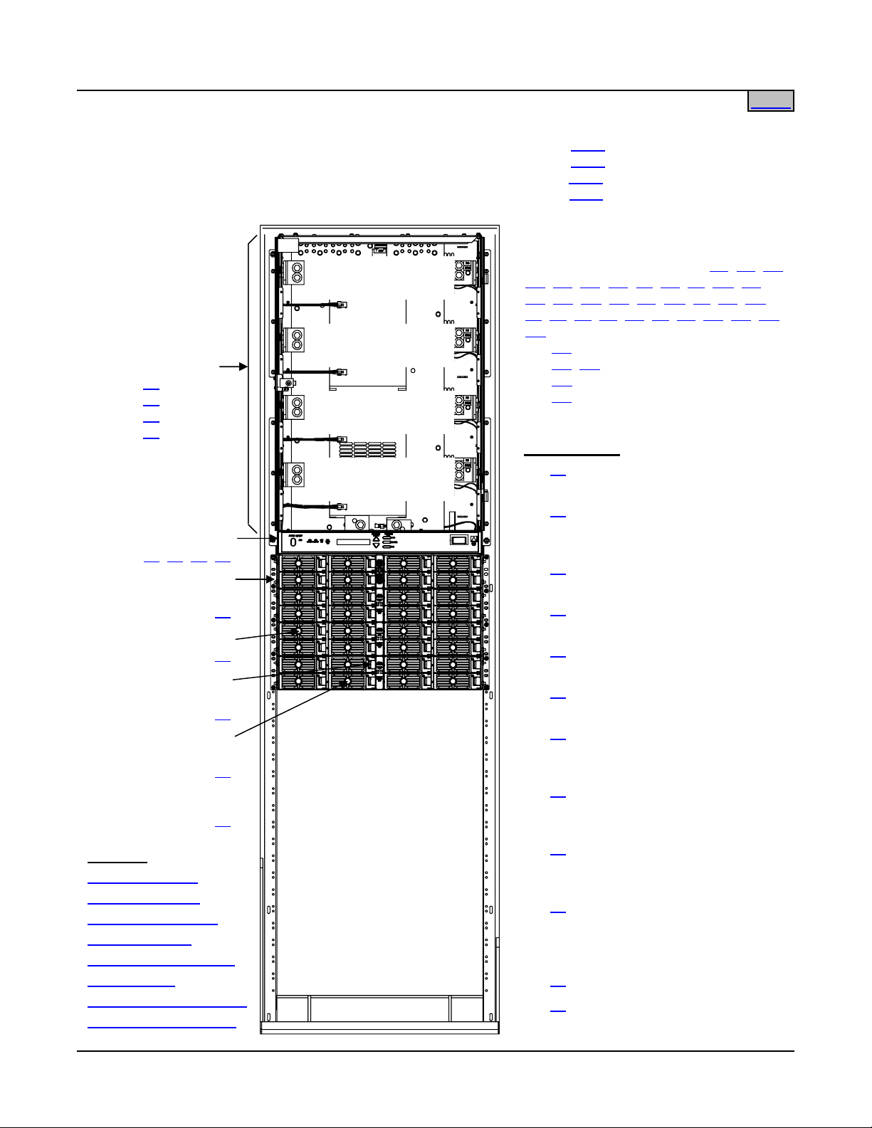
• Distribution Cabinet
SAG581126000
System Application Guide
Spec. No. 581126000 (Model 700
Issue AD, November 23, 2009
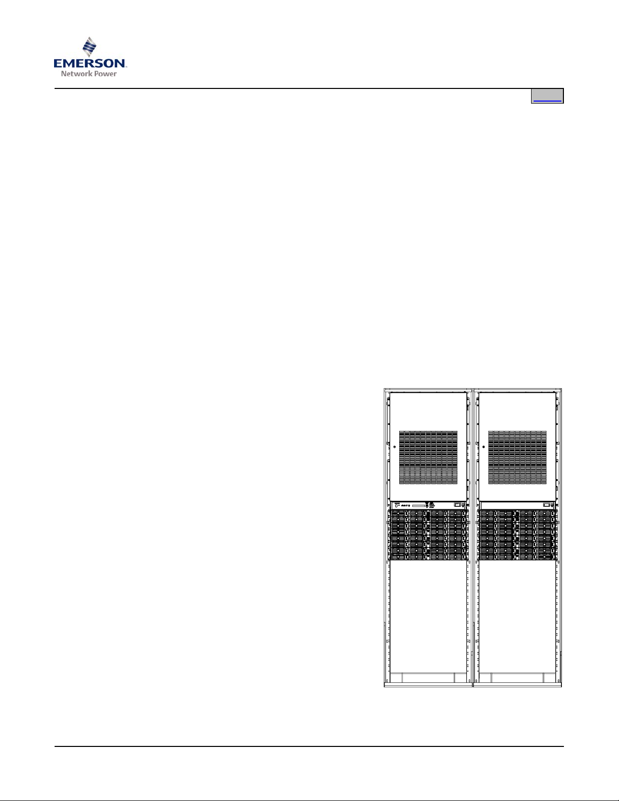
ETSURE™ 700NVBA DC Power System is a complete integrated power system
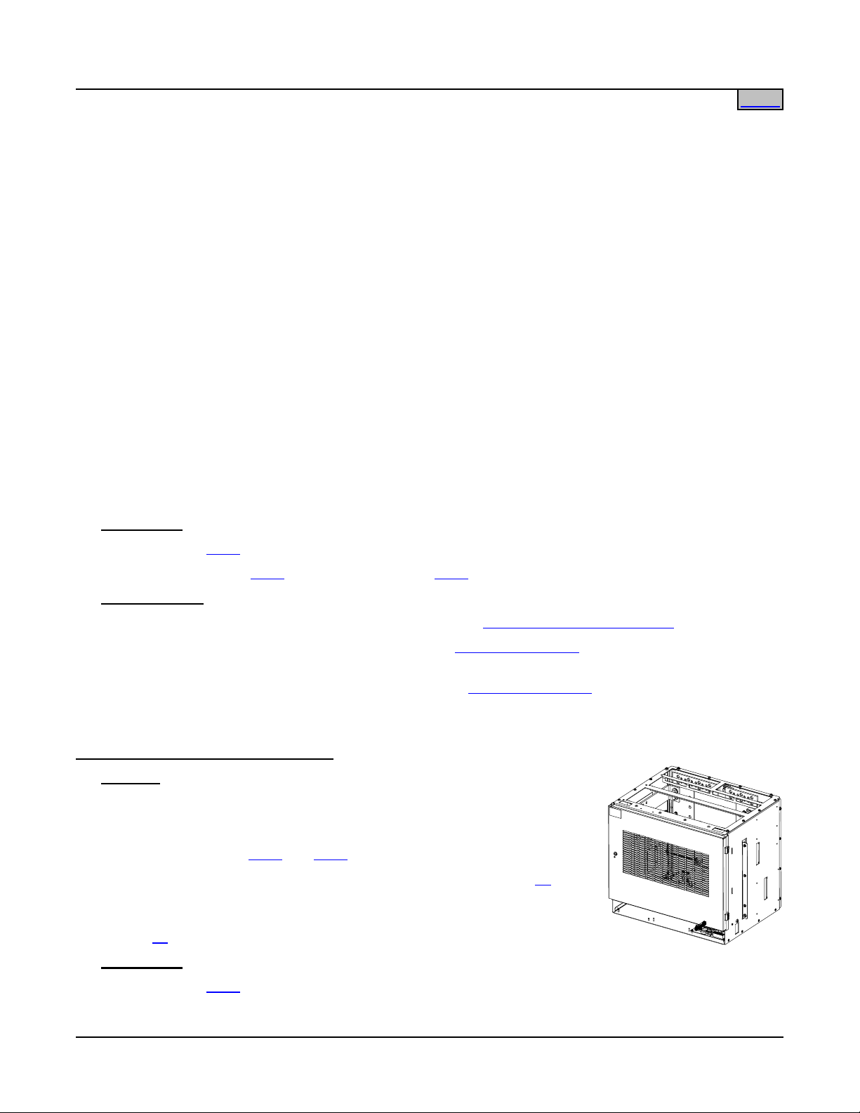
The system always includes a minimum of one Distribution Cabinet (one per bay),
which provides DC distribution through fuses and/or circuit breakers.
Four different sizes of Distribution Cabinets may be ordered to accept from one (1) to
four (4) Distribution Bus Panel assemblies. A variety of Distribution Bus Panel
assemblies are available that provide combinations of load distribution, battery
distribution, low voltage load or battery disconnect, manual battery disconnect, and
dual voltage load distribution for use with -48V converters. The Distribution Cabinet
is factory mounted in the relay rack specified when ordered.
NVBA)
Home
Most of the distribution panels accept either TPS/TLS-type fuseholders or Bullet
Nose-type circuit breakers. TPH-type fuses and GJ/218-type circuit breakers are
also available, in ratings up to 600 amps.
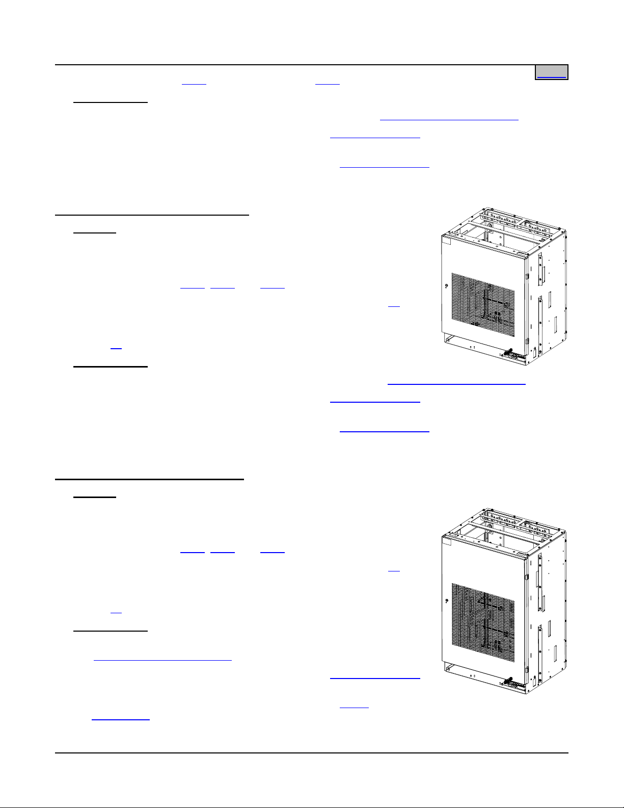
• Meter-Control-Alarm (MCA) Assem bly
The system contains one MCA. The MCA
controls the operation of the Rectifier
Modules (PCUs). The MCA also provides
power system control, metering,
monitoring, and alarm functions.
• Module Mounting Assembly
The system contains one or more Module
Mounting Assemblies (one per bay), each
of which houses Rectifier Modules (PCUs)
and optional DC-DC Converter Modules.
Refer to PD588705100 (PD588705101,
PD588705102, PD588705103,
PD588705104) for more information.
• Rectifier Modules (PCUs)
The system contains Rectifier Modules
(PCUs), which provide load power, battery
float current, and battery recharge current
during normal operating conditions. Refer
to PD588705100 (PD588705101,
PD588705102, PD588705103,
PD588705104) for more information.
Page 1 of 123
This document is property of Emerson Network Power, Energy Systems, North America, Inc. and contains confidential and proprietary information owned by Emerson Network Power, Energy
Systems, North America, Inc. Any copying, use, or disclosure of it without the written permission of Emerson Network Power, Energy Systems, North America, Inc. is strictly prohibited.
Page 2

SAG581126000 System Application Guide
Issue AD, November 23, 2009 Spec. No. 581126000 (Model 700
• Optional DC-DC Converter Modules
NVBA)
Home
Where –48VDC load power is also required, DC-DC Converter Modules are
available. Refer to PD588705100 (PD588705101, PD588705102, PD588705103,
PD588705104) for more information.
Family: N
ETSURE™
Spec. No.: 581126000
Model: 700
NVBA
Rectifier Input Voltage Nominal 208-240 volts AC, single phase, 50/60 Hz, with an operating
range of 180 to 264 volts. Acceptable input frequency range is 47 to 65
Hz.
Rectifier Output Voltage: +24 Volts DC
Converter Output Voltage: -48 Volts DC
Output Capacity:
System: 4000 Amperes, maximum
Bay: 2000 Amperes, maximum (1500A maximum when equipped with List
AH; 1200A maximum when equipped with List RA or RB)
Distribution Bus Panel: 500 Amperes, maximum (List
ND rated for 960A)
Rectifier Module (PCU): 87.7A @ +28.5VDC to 104.2A @ +24.0VDC, 2500 Watts
Converter Module: 31 Amperes (1500W)
Agency Approval:
UL 1801 Listed (“c UL”), NEBS (pending)
Framework Type: Relay Rack
Mounting Width: 23 Inches, nominal
Mounting Depth:
Distribution Cabinet: 18 Inches (single-bay), 21 Inches (multi-bay)
RC, RD, and RE adds 5.25 inches to back of system, see Overall
(List
Dimensions Illustrations)
Module Mounting Assembly: 22.34 Inches
Access: Front, Sides, and Rear for Installation and Maintenance,
Front for Operation
Supplemental Bay(s) Available: One
Control: Microprocessor
Color: Bay and Rectifier Module Faceplates: Textured Gray (Spec. M500-147)
Rectifier Shelf and Rectifier Modules Bodies: Bright Zinc Plating (Spec.
M500-53)
List Options:
Main Bay, Supplemental Bay (located next to Main Bay), Supplemental
Bay 'Distribution Only' Option, Supplemental Bay (located away from
Main Bay), MCA (standard), MCA (special application), MCA (special
application), MCA (special application), 1-Row Distribution Cabinet,
2-Row Distribution Cabinet, 3-Row Distribution Cabinet, 4-Row
Distribution Cabinet, Distribution Cabinet Top Shield, Module Mounting
Assembly Interface Components, Field Expansion Kit (One [1] 8-Position
Module Mounting Assembly), Rectifier Module (PCU), DC-DC Converter
Option Interface Component Kit, DC-DC Converter Module, Audible
Alarm and Alarm Termination Card, MCA Interface Modem Option, MCA
Page 2 of 123
This document is property of Emerson Network Power, Energy Systems, North America, Inc. and contains confidential and proprietary information owned by Emerson Network Power, Energy
Systems, North America, Inc. Any copying, use, or disclosure of it without the written permission of Emerson Network Power, Energy Systems, North America, Inc. is strictly prohibited.
Page 3

System Application Guide SAG581126000
Spec. No. 581126000 (Model 700
NVBA) Issue AD, November 23, 2009
Interface WinLink Software, MCA Interface Combination
Home
Modem/RS-232 Option, MCA Interface Ethernet Option
(WinLink Compatible + Web Interface), MCA Interface Ethernet Option
(WinLink Compatible + Web Interface + SNMP), MCA Interface Ethernet
Option (WinLink Compatible + Web Interface + Battery Monitoring), MCA
Interface Ethernet Option (WinLink Compatible + Web Interface + SNMP
+ Battery Monitoring), Battery Stand System, Battery Tray (Pre-Cabled),
Distribution Panels
Accessories Options:
Environment:
Relay Racks, Transition Plates, Distribution Devices, Wiring
Components, Module Mounting Position Blank Cover Panel, Battery
Charge Temperature Compensation Probe for Single Probe Digital
Compensation, Battery Charge Temperature Compensation Probe
Concentrator for Multiple Probe Use (TXM), Battery Busbar Extension
Kit, Battery Busbar Extension Kit, Lug Adapter Busbar, Lug Adapter
Busbar Kit, Lug Adapter Busbar Kit, Lug Hardware Kit, LVD Contactor
Bypass Kit, Replacement Cables, Replacement Components
-40°C to +40°C (-40°F to +104°F)
Page 3 of 123
This document is property of Emerson Network Power, Energy Systems, North America, Inc. and contains confidential and proprietary information owned by Emerson Network Power, Energy
Systems, North America, Inc. Any copying, use, or disclosure of it without the written permission of Emerson Network Power, Energy Systems, North America, Inc. is strictly prohibited.
Page 4
SAG581126000 System Application Guide
Issue AD, November 23, 2009 Spec. No. 581126000 (Model 700
NVBA)
Home
581126000
Distribution Cabinet
24 (4-Row)
List
23 (3-Row)
List
22 (2-Row)
List
21 (1-Row)
List
MCA
10, 11, 12, 13
List
Module Mounting
Assembly Interface
30
List
Rectifier Module
50
List
DC-DC Converter Option
Interface Component Kit
60
List
Optional DC-DC
Converter Module
62
List
or
Rectifier Module
50
List
Main Bay:……………………………………………...…List 1
Supplemental Bay (located next to Main Bay):………
Supplemental Bay 'Distribution Only' Option:………..
Supplemental Bay (located away from Main Bay):….
Distribution Bus
Row D (Row 4)
Distribution Bus
Row C (Row 3)
Distribution Bus
Distribution Assembly List AA, AB, AC,
AD, AE, AG, AH, AJ, AK, AL, AM, BA,
CA, CB, CD, CE, CF, CG, CJ, EA, GB,
JA, JB, JC, JD, KA, LB, LC, NA, NB, NC,
ND
List
List
List
List
List 2
List 4
List 5
RA: LV Battery Disconnect
RB, RC: Manual Battery Disconnect
RD: LV/Manual Battery Disconnect
RE: LV Battery Disconnect
Row B (Row 2)
Other Options
Distribution Bus
Row A (Row 1)
List
29: Distribution Cabinet Top
Shield
31: Field Expansion Kit: One
List
(1) 8-Position Module Mounting
Assembly
71: Optional Audible Alarm and
List
Alarm Termination Circuit Card
List
72: MCA Interface Modem
Option
List
73: MCA Interface WinLink
Software
List
74: MCA Interface Combination
Modem/RS-232 Option
75: MCA Interface Ethernet
List
Option: WinLink Compatible + Web
Interface
76: MCA Interface Ethernet
List
Option: WinLink Compatible + Web
Interface + SNMP
77: MCA Interface Ethernet
See Also
System Overview
Table of Contents
Ordering Information
List Descriptions
Accessory Descriptions
Specifications
Physical Size Information
Related Documentation
Page 4 of 123
This document is property of Emerson Network Power, Energy Systems, North America, Inc. and contains confidential and proprietary information owned by Emerson Network Power, Energy
Systems, North America, Inc. Any copying, use, or disclosure of it without the written permission of Emerson Network Power, Energy Systems, North America, Inc. is strictly prohibited.
List
Option: WinLink Compatible + Web
Interface + Battery Monitoring
78: MCA Interface Ethernet
List
Option: WinLink Compatible + Web
Interface + SNMP + Battery
Monitoring
92: Battery Stand System
List
93: Battery Tray
List
Page 5

System Application Guide SAG581126000
Spec. No. 581126000 (Model 700
NVBA) Issue AD, November 23, 2009
TABLE OF CONTENTS
Ordering Information
System
Overview
Picture
List
Descriptions
Accessory
Descriptions
Specifications
SYSTEM OVERVIEW.................................................................................................................................................1
TABLE OF CONTENTS.............................................................................................................................................5
ORDERING INFORMATION......................................................................................................................................9
List Options..........................................................................................................................................................9
List Options (Numbers) ....................................................................................................................................9
List Options (Letters) (Distribution Bus Arrangements).................................................................................11
Accessory Options............................................................................................................................................15
LIST DESCRIPTIONS..............................................................................................................................................16
List 1: Main Bay Common Equipment (Power and Distribution)...................................................................16
List 2: Supplemental Bay Common Equipment (Power and Distribution) (located next to Main Bay) .........17
List 4: “Distribution Only” Option for Lists 2 or 5...........................................................................................18
List 5: Supplemental Bay Common Equipment (Power and Distribution) (located away from Main
Bay)................................................................................................................................................................
List 10: MCA (Standard Application).............................................................................................................19
List 11: MCA (Special Application)................................................................................................................19
List 12: MCA (Special Application)................................................................................................................20
List 13: MCA (Special Application)................................................................................................................20
List 21: One-Row Distribution Cabinet..........................................................................................................20
List 22: Two-Row Distribution Cabinet..........................................................................................................21
List 23: Three-Row Distribution Cabinet.......................................................................................................22
List 24: Four-Row Distribution Cabinet .........................................................................................................22
List 29: Top Shield for Distribution Cabinet...................................................................................................23
List 30: Module Mounting Assembly Interface Components.........................................................................23
List 31: Field Expansion Kit: One (1) 8-Position Module Mounting Assembly.............................................24
List 50: Rectifier Module (PCU).....................................................................................................................25
List 60: DC-DC Converter Option Interface Component Kit .........................................................................25
List 62: DC-DC Converter Module ................................................................................................................26
List 71: Optional Audible Alarm and Alarm Termination Circuit Card...........................................................26
List 72: MCA Interface Modem Option..........................................................................................................26
List 73: MCA Interface WinLink Software .....................................................................................................27
List 74: MCA Interface Combination Modem/RS-232 Option.......................................................................27
List 75: MCA Interface Ethernet Option: WinLink Compatible + Web Interface ...........................................28
List 76: MCA Interface Ethernet Option: WinLink Compatible + Web Interface + SNMP.............................28
List 77: MCA Interface Ethernet Option: WinLink Compatible + Web Interface + Battery Monitoring..........29
List 78: MCA Interface Ethernet Option: WinLink Compatible + Web Interface + SNMP + Battery
Monitoring.......................................................................................................................................................
List 92: Battery Stand System.......................................................................................................................30
List 93: Battery Tray, Pre-Cabled..................................................................................................................30
List AA: Distribution Bus Module (P/N 509840) (24) Fuse/Circuit Breaker System Positions......................33
List AB: Distribution Bus Module (P/N 428316100) (3) GJ/218 Circuit Breaker System Positions..............34
List AC: Distribution Bus Module (P/N 507198) (3) GJ/218 Circuit Breaker System Positions....................35
List AD: Distribution Bus Module (P/N 509565) (8) GJ/218 Circuit Breaker System Positions
(Upper Two Rows) .........................................................................................................................................
List AE: Distribution Bus Module (P/N 509648) (8) GJ/218 Circuit Breaker System Positions
(Lower Two Rows) .........................................................................................................................................
Physical Size
Information
Related
Documentation
18
29
36
37
Page 5 of 123
This document is property of Emerson Network Power, Energy Systems, North America, Inc. and contains confidential and proprietary information owned by Emerson Network Power, Energy
Systems, North America, Inc. Any copying, use, or disclosure of it without the written permission of Emerson Network Power, Energy Systems, North America, Inc. is strictly prohibited.
Page 6

SAG581126000 System Application Guide
Issue AD, November 23, 2009 Spec. No. 581126000 (Model 700
NVBA)
List AG: Distribution Bus Module (P/N 514010) (2) TPH Fuse System Positions........................................38
List AH: Distribution Bus Module Ground Bar Assembly (P/N 500676) for Use with Up to (2) List
AG, AJ, CG, or CJ..........................................................................................................................................
39
List AJ: Distribution Bus Module (P/N 520819) (2) TPH Fuse System Positions with Load Metering
Shunts............................................................................................................................................................
40
List AK: Distribution Bus Module (P/N 520805) (24) Fuse/Circuit Breaker System Positions......................41
List AL: Distribution Bus Module Ground Bar Assembly for Use with Up to (2) List AK...............................42
List AM: Distribution Bus Module (P/N 524632) (20) Fuse/Circuit Breaker System Positions (1) 3-
Pole Input Disconnect Fuse/Circuit Breaker Position ....................................................................................
43
List BA: Distribution Bus Module (P/N 520534) (12) Fuse/Circuit Breaker System Positions with
LVD (8) Fuse/Circuit Breaker System Positions without LVD........................................................................
44
List CA: Distribution Bus Module (P/N 509848) (20) Fuse/Circuit Breaker System Positions
w/LVLD...........................................................................................................................................................
45
List CB: Distribution Bus Module (P/N 513738) (3) GJ/218 Circuit Breaker System Positions
w/LVLD...........................................................................................................................................................
46
List CD: Distribution Bus Module (P/N 507200) (3) GJ/218 Circuit Breaker System Positions
w/LVLD...........................................................................................................................................................
47
List CE: Distribution Bus Module (P/N 509564) (8) GJ/218 Circuit Breaker System Positions
w/LVLD (Upper Two Rows)............................................................................................................................
48
List CF: Distribution Bus Module (P/N 509647) (8) GJ/218 Circuit Breaker System Positions
w/LVLD (Lower Two Rows)............................................................................................................................
49
List CG: Distribution Bus Module (P/N 514035) (2) TPH Distribution Fuse Positions w/LVLD....................50
List CJ: Distribution Bus Module (P/N 520936) (2) TPH Distribution Fuse Positions with Load
Metering Shunts and LVLD............................................................................................................................
51
List EA: Distribution Bus Module (P/N 509852) (16) Fuse/Circuit Breaker System Positions and (4)
Fuse/Circuit Breaker Battery Disconnect Positions .......................................................................................
52
List GB: Distribution Bus Module (P/N 513806) (8) Fuse/Circuit Breaker System Positions w/LVD
and (1) TPH Fuse Battery Disconnect Position .............................................................................................
53
List JA: Distribution Bus Module (Part No. 509906) (4) +24V Fuse/Circuit Breaker System
Positions and (16) –48V Fuse/Circuit Breaker Subsystem Positions ...........................................................
54
List JB: Distribution Bus Module (Part No. 513808) (12) +24V Fuse/Circuit Breaker System
Positions and (8) –48V Fuse/Circuit Breaker Subsystem Positions.............................................................
55
List JC: Distribution Bus Module (Part No. 524403) (14) +24V Fuse/Circuit Breaker System
Positions and (6) –48V Fuse/Circuit Breaker Subsystem Positions.............................................................
56
List JD: Distribution Bus Module (Part No. 524788) (14) +24V Fuse/Circuit Breaker System
Positions and (8) –48V Fuse/Circuit Breaker Subsystem Positions ..............................................................
57
List KA: Distribution Bus Module (Part No. 520507) (4) +24V Fuse/Circuit Breaker System
Positions and (16) –48V Fuse/Circuit Breaker Subsystem Positions ...........................................................
58
List LB: Distribution Bus Module (Part No. 513807) (8) +24V Fuse/Circuit Breaker System
Positions w/LVD and (8) –48V Fuse/Circuit Breaker Subsystem Positions ..................................................
59
List LC: Distribution Bus Module (Part No. 514623) (12) +24V Fuse/Circuit Breaker System
Positions w/LVD and (4) –48V Fuse/Circuit Breaker Subsystem Positions ..................................................
60
List NA: Distribution Bus Module (P/N 514336) (20) Fuse/Circuit Breaker Battery Disconnect
Positions.........................................................................................................................................................
61
List NB: Distribution Bus Module (P/N 513809) (3) GJ/218 Circuit Breaker Battery Disconnect
Positions.........................................................................................................................................................
62
List NC: Distribution Bus Module (P/N 514025) (1) TPH Fuse Battery Disconnect Position........................63
List ND: Distribution Bus Module (P/N 514030) (2) TPH Fuse Battery Disconnect Positions......................64
List RA: 1200A Low Voltage Battery Disconnect (LVBD) Contactor and Control Circuit (P/N
540808)..........................................................................................................................................................
65
List RB: 1200A Manual Battery Disconnect Contactor with Local and Remote Alarm (P/N 540809) ..........66
List RC: 2000A Manual Battery Disconnect Contactor with Local and Remote Alarm (P/N 528446)..........67
List RD: 2000A Low Voltage/Manual Battery Disconnect Contactor with Battery Current Monitoring
(P/N 528447)..................................................................................................................................................
68
List RE: 2000A Low Voltage Battery Disconnect Contactor with Battery Current Monitoring (P/N
535064)..........................................................................................................................................................
69
Page 6 of 123
This document is property of Emerson Network Power, Energy Systems, North America, Inc. and contains confidential and proprietary information owned by Emerson Network Power, Energy
Systems, North America, Inc. Any copying, use, or disclosure of it without the written permission of Emerson Network Power, Energy Systems, North America, Inc. is strictly prohibited.
Page 7

System Application Guide SAG581126000
Spec. No. 581126000 (Model 700
NVBA) Issue AD, November 23, 2009
ACCESSORY DESCRIPTIONS...............................................................................................................................70
Relay Racks .......................................................................................................................................................70
Transition Plates to Mount Relay Rack on Top of GNB Absolyte IIP Batteries..........................................71
Distribution Devices..........................................................................................................................................72
GMT Load Distribution Fuse Block Assembly Kit (P/N 514432) (10) GMT Fuse Positions...........................72
GMT-Type Load Distribution Fuses...............................................................................................................73
Replacement Alarm, Reference, and Control Fuses .....................................................................................74
TPH-Type Fuses............................................................................................................................................75
GJ/218-Type Circuit Breakers........................................................................................................................76
Bullet Nose-Type Circuit Breakers and Bullet Nose-Type Fuseholders e/w TPS/TLS Fuses.......................78
Wiring Components ..........................................................................................................................................81
Load Distribution Wire Sizes and Lugs Selection................................................................................ ..........81
Input Battery Wire Sizes and Lugs Selection.................................................................................................82
Standard Crimp Lug Tables...........................................................................................................................84
Special Application Crimp Lug / Strap Combination Table............................................................................85
Wire Size and Lug Selection Tables for Load and Battery Connections to TPS/TLS Fuses and
Bullet Nose-Type Circuit Breakers or Battery Branch Circuits.......................................................................
86
Wire Size and Lug Selection Tables for Load and Battery Connections to TPH Fuses and GJ/218-
Type Circuit Breakers or Battery Branch Circuits ..........................................................................................
88
AC Input Branch Circuit Protection and Wire Size Selection.........................................................................90
Relay Rack Frame Grounding Requirements........................................................................................ ........90
External Alarm, Reference, and Control Wire Sizes......................................................................................90
Module Mounting Position Blank Cover Panel (P/N 540959)........................................................................91
Battery Charge Temperature Compensation Probe for Single Probe Digital Compensation (P/Ns
107021 and 106824)...........................................................................................................................................
91
Battery Charge Temperature Compensation Probe Concentrator for Multiple Probe Use (TXM)............91
Battery Temperature Probe Concentrator Kit (P/N 524570)..........................................................................91
Analog Battery Temperature Probe (P/N 521262).........................................................................................92
TXM Extension Cable (P/N 514153)..............................................................................................................92
Battery Busbar Extension Kit (P/N 514713)....................................................................................................92
Battery Busbar Extension Kit (P/N 529143)....................................................................................................92
Lug Adapter Busbar for 250 Amp Bullet Nose Type Circuit Breaker (P/N 514717)....................................93
Lug Adapter Busbar Kit for 125-200 Amp Bullet Nose Type Circuit Breaker (P/N 534449).......................93
Lug Adapter Busbar Kit for 250 Amp Bullet Nose Type Circuit Breaker (P/N 514714)..............................93
Bullet Distribution Assembly Lug Hardware Kit (P/N 520332)......................................................................93
LVD Contactor Bypass Kits (P/Ns 514910 and 514912) ................................................................................94
Replacement Cables .........................................................................................................................................95
Replacement Components...............................................................................................................................98
SPECIFICATIONS....................................................................................................................................................99
1.1 Environmental Ratings...............................................................................................................................99
1.2 Compliance Information.............................................................................................................................99
1.3 MCA Features..............................................................................................................................................99
PHYSICAL SIZE INFORMATION..........................................................................................................................109
Overall Dimensions.........................................................................................................................................109
List 24 (Four Bus Row Cabinet)...................................................................................................................109
List 23 (Three Bus Row Cabinet).................................................................................................................110
List 22 (Two Bus Row Cabinet)....................................................................................................................111
List 21 (One Bus Row Cabinet)....................................................................................................................112
List 93 (Battery Tray)....................................................................................................................................113
Optional Digital Battery Charge Temperature Compensation Probe (P/N 107021 and 106824)................114
Optional Analog Battery Temperature Probe (P/N 521262)........................................................................114
Electrical Connection Locations and Dimensions.......................................................................................115
Input Battery.................................................................................................................................................115
Load Distribution ..........................................................................................................................................119
AC Input .......................................................................................................................................................119
Page 7 of 123
This document is property of Emerson Network Power, Energy Systems, North America, Inc. and contains confidential and proprietary information owned by Emerson Network Power, Energy
Systems, North America, Inc. Any copying, use, or disclosure of it without the written permission of Emerson Network Power, Energy Systems, North America, Inc. is strictly prohibited.
Page 8

SAG581126000 System Application Guide
Issue AD, November 23, 2009 Spec. No. 581126000 (Model 700
NVBA)
External Alarm, Reference, and Control ......................................................................................................120
RELATED DOCUMENTATION..............................................................................................................................121
BATTERY MANUFACTURER INFORMATION ....................................................................................................122
REVISION RECORD..............................................................................................................................................123
Page 8 of 123
This document is property of Emerson Network Power, Energy Systems, North America, Inc. and contains confidential and proprietary information owned by Emerson Network Power, Energy
Systems, North America, Inc. Any copying, use, or disclosure of it without the written permission of Emerson Network Power, Energy Systems, North America, Inc. is strictly prohibited.
Page 9

System Application Guide SAG581126000
Spec. No. 581126000 (Model 700
NVBA) Issue AD, November 23, 2009
Home
ORDERING INFORMATION
List Options
Order the following by the items Part Number as specified in the following table.
When viewing electronically, click on the List # to jump to the detailed description page.
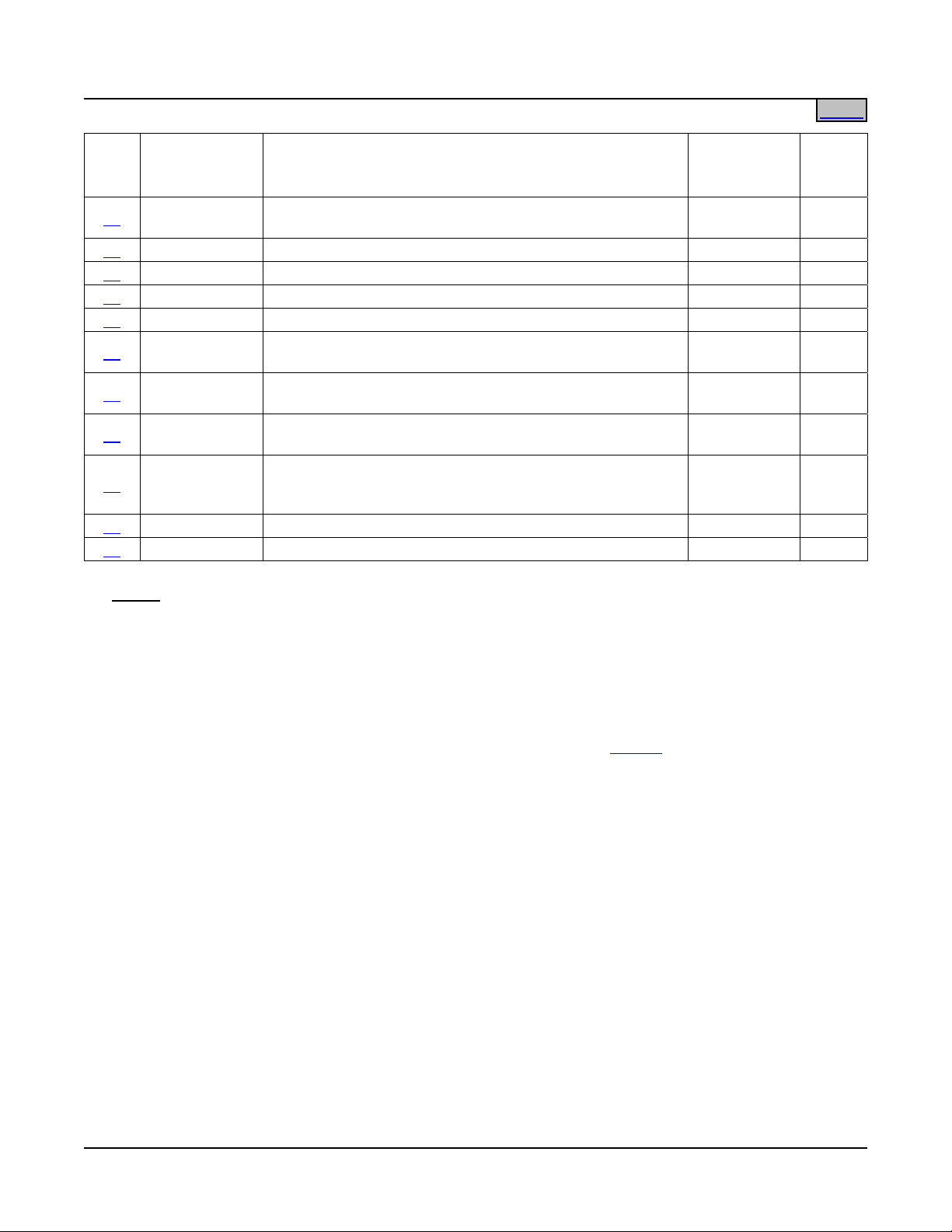
List Options (Numbers)
List
No.
Part Number Description
Mounting
Positions
(1U = 1-3/4”)
Main Bay Common Equipment (Power and Distribution).
1 58112600001
Accepts Distribution Cabinet (List 21, 22, 23, or 24) with
MCA (List 10, 11, 12, or 13) and Module Mounting
-- 1, 2
Assembly Interface (List 30).
Supplemental Bay Common Equipment (Power and
Distribution). Includes interbay power busbars and
2 58112600002
communication cable. Accepts Distribution Cabinet (List
-- 1, 2
23 or 24) and Module Mounting Assembly Interface (List
30).
4 58112600004
“Distribution Only” option for List 2 or 5. Configures the
bay for use without Module Mounting Assembly.
--
Remote Supplemental Bay Common Equipment (Power
and Distribution). Includes communication cable.
5 58112600005
Requires interbay power cabling. Accepts Distribution
-- 1, 2
Cabinet (List 21, 22, 23, or 24) and Module Mounting
Assembly Interface (List 30).
10 58112600010
11 58112600011
12 58112600012
13 58112600013
MCA - Standard Application (Configuration No. 534876)
(installed in Main Bay Distribution Cabinet).
MCA - Special Application (Configuration No. 534877)
(installed in Main Bay Distribution Cabinet).
MCA - Special Application (Configuration No. 534878)
(installed in Main Bay Distribution Cabinet).
MCA - Special Application (Configuration No. 534879)
(installed in Main Bay Distribution Cabinet).
-- 1, 2
-- 1, 2
-- 1, 2
-- 1, 2
21 58112600021 1-Row Distribution Cabinet (for use in List 1 and 5). 7U 1, 2
22 58112600022 2-Row Distribution Cabinet (for use in List 1 and 5). 11U 1, 2
23 58112600023 3-Row Distribution Cabinet (for use in List 1, 2, and 5). 15U 1, 2
24 58112600024 4-Row Distribution Cabinet (for use in List 1, 2, and 5). 19U 1, 2
29 58112600029 Top Shield for Distribution Cabinet. -- --
30 58112600030
Interface Components for one (1) 588705101, 588705102,
588705103, or 588705104 Module Mounting Assembly.
2U to 8U 1, 2, 3
Field Expansion Kit. Provides one (1) 588705100
31 58112600031
8-Position Module Mounting Assembly and components
2U --
required for field installation in a Power System.
50 58112600050
60 58112600060
Model R24-2500 Rectifier Module (PCU)
(for use in List 30 and 31).
DC-DC Converter Option Interface Component Kit
(for use in List 30 and 31).
-- 1, 2
-- --
Notes
Page 9 of 123
This document is property of Emerson Network Power, Energy Systems, North America, Inc. and contains confidential and proprietary information owned by Emerson Network Power, Energy
Systems, North America, Inc. Any copying, use, or disclosure of it without the written permission of Emerson Network Power, Energy Systems, North America, Inc. is strictly prohibited.
Page 10
SAG581126000 System Application Guide
Issue AD, November 23, 2009 Spec. No. 581126000 (Model 700
NVBA)
Home
List
No.
Part Number Description
62 58112600062
Optional Model C24/48-1500 DC-DC Converter Module
(for use in List 30 and 31).
Mounting
Positions
Notes
(1U = 1-3/4”)
-- --
71 58112600071 Audible Alarm and Alarm Termination Card. -- 4
72 58112600072 MCA Interface Modem Option. -- --
73 58112600073 MCA Interface WinLink Software. -- --
74 58112600074 MCA Interface Combination Modem/RS-232 Option. -- --
75 58112600075
76 58112600076
77 58112600077
MCA Interface Ethernet Option
(WinLink Compatible, Web Interface).
MCA Interface Ethernet Option
(WinLink Compatible, Web Interface, SNMP).
MCA Interface Ethernet Option
(WinLink Compatible, Web Interface, Battery Monitoring).
-- --
-- --
-- -MCA Interface Ethernet Option
78 58112600078
(WinLink Compatible, Web Interface, SNMP, Battery
-- -Monitoring).
92 58112600092 Battery Stand System -- --
93 58112600093 Battery Tray, Pre-Cabled. As requested --
Notes:
1) This power system must consist of a minimum configuration of…
(1) List 1
(1) List 10, 11, 12, or 13
(1) List 21, 22, 23, or 24
(1) List 30 equipped w/ List 50's
A maximum of one supplemental bay (List 2 or 5) may be added to the system.
2) Separately order one relay rack for each bay (List
1, 2, and 5). See Table 1 in the ACCESSORY
DESCRIPTIONS section for available relay racks. Distribution Panels, Rectifier Modules (PCUs),
Converters, and Module Mounting Assembly list options must be specified when ordering. Module
Mounting Assembly must be ordered separately.
Note: System components may be ordered without a relay rack. When ordered without a relay rack, the
system is mounted on shipping brackets bolted to a shipping skid. The shipping brackets can
mount a system up to 20U high.
3) Includes Module Mounting Assembly to Distribution Cabinet interconnect components only. Module
Mounting Assembly is not included in List 30. Order Module Mounting Assembly separately per
PD588705101, PD588705102, PD588705103, PD588705104.
4) Use alarm cable P/N 514327 (15' 0" cable) when List 71 is not ordered (List 1 provides this cable). For a
longer cable, P/N 514380 (60’) is available.
Page 10 of 123
This document is property of Emerson Network Power, Energy Systems, North America, Inc. and contains confidential and proprietary information owned by Emerson Network Power, Energy
Systems, North America, Inc. Any copying, use, or disclosure of it without the written permission of Emerson Network Power, Energy Systems, North America, Inc. is strictly prohibited.
Page 11
System Application Guide SAG581126000
Spec. No. 581126000 (Model 700
NVBA) Issue AD, November 23, 2009
Home
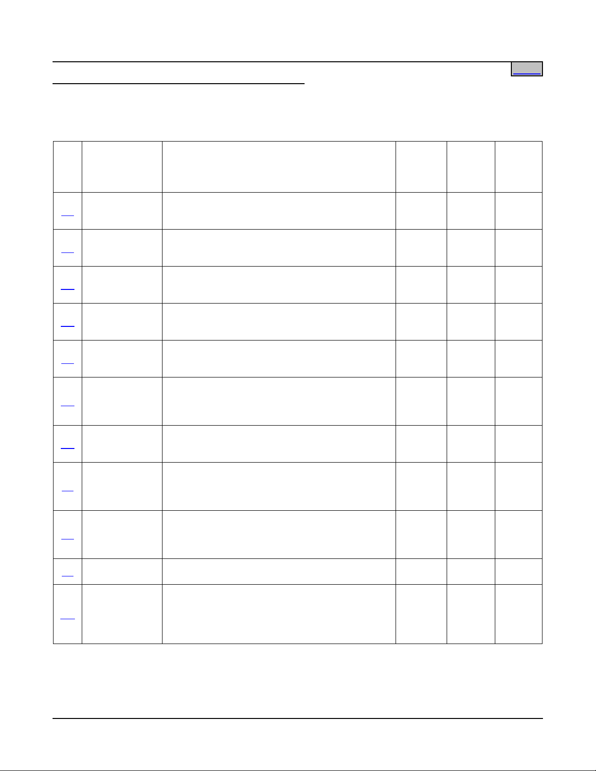
List Options (Letters) (Distribution Bus Arrangements )
If Low Voltage Disconnect (LVD) is required, each distribution row that is to operate from an LVD
must have an LVD provided in the specific panel ordered for that row.
Rows are numbered one through four (A through D) from bottom to top.
List
No.
Part Number Description
AA 581126000AA
AB 581126000AB
AC 581126000AC
AD 581126000AD
AE 581126000AE
AG 581126000AG
AH 581126000AH
AJ 581126000AJ
AK 581126000AK
AL 581125000AL
AM 581126000AM
Distribution.
(24) Bullet Nose Circuit Breaker and/or TPS/TLS
Fuse +24V System Positions.
Distribution.
(3) GJ/218 Circuit Breaker +24V System Positions.
(rows 1, 2, 3 only)
Distribution.
(3) GJ/218 Circuit Breaker +24V System Positions.
(row 4 only)
Distribution.
(8) GJ/218 Circuit Breaker +24V System Positions.
(rows 3 and 4 [C and D])
Distribution.
(8) GJ/218 Circuit Breaker +24V System Positions.
(rows 1 and 2 [A and B] or rows 2 and 3 [B and C])
Distribution.
(2) TPH Fuse +24V System Position s.
[Need (1) List AH for up to (2) List AG if internal
load returns are required.]
Ground Bar Assembly for use with up to (2) List
AG, AJ, CG, or CJ if internal load returns are
required.
Distribution.
(2) TPH Fuse +24V System Positions with Load
Shunts. [Need (1) List AH for up to (2) List AJ if
internal load returns are required.]
Distribution.
(24) Bullet Nose Circuit Breaker and/or TPS/TLS
Fuse +24V System Positions.
(no ground return busbar provided)
Ground Bar Assembly for use with up to (2) List AK
if internal load returns are required.
Distribution.
(20) Bullet Nose Circuit Breaker and/or TPS/TLS
Fuse +24V System Positions.
(1) Bullet Nose Circuit Breaker and/or TPS/TLS
Fuse 3-Pole +24V Input Disconnect Position.
Single
or Dual
Voltage
Low
Volt.
Load
Disc.
Battery
Disc.
Single No No
Single No No
Single No No
Single No No
Single No No
Single No No
N/A No No
Single No No
Single No No
N/A No No
Single No No
Page 11 of 123
This document is property of Emerson Network Power, Energy Systems, North America, Inc. and contains confidential and proprietary information owned by Emerson Network Power, Energy
Systems, North America, Inc. Any copying, use, or disclosure of it without the written permission of Emerson Network Power, Energy Systems, North America, Inc. is strictly prohibited.
Page 12

SAG581126000 System Application Guide
Issue AD, November 23, 2009 Spec. No. 581126000 (Model 700
NVBA)
Low
Volt.
Load
Disc.
Battery
Disc.
List
No.
Part Number Description
Single
or Dual
Voltage
Distribution.
(12) LVD-Controlled Bullet Nose Circuit Breaker
BA 581126000BA
and/or TPS/TLS Fuse +24V System Positions.
Single Yes No
(8) Non-LVD-Controlled Bullet Nose Circuit Breaker
and/or TPS/TLS Fuse +24V System Positions.
Distribution.
CA 581126000CA
(20) LVD-Controlled Bullet Nose Circuit Breaker
Single Yes No
and/or TPS/TLS Fuse +24V System Positions.
Distribution.
CB 581126000CB
(3) LVD-Controlled GJ/218 Circuit Breaker
Single Yes No
+24V System Positions. (rows 1, 2, 3 only)
Distribution.
CD 581126000CD
(3) LVD-Controlled GJ/218 Circuit Breaker
Single Yes No
+24V System Positions. (row 4 only)
Distribution.
CE 581126000CE
(8) LVD-Controlled GJ/218 Circuit Breaker
Single Yes No
+24V System Positions. (rows 3 and 4)
Distribution.
CF 581126000CF
(8) LVD-Controlled GJ/218 Circuit Breaker
+24V System Positions.
Single Yes No
(rows 1 and 2, or rows 2 and 3)
Distribution.
CG 581126000CG
(2) LVD-Controlled TPH Fuse +24V System
Positions. [Need (1) List AH for up to (2) List CG if
Single Yes No
internal load returns are required.]
Distribution.
(2) LVD-Controlled TPH Fuse +24V System
CJ 581126000CJ
Positions with Load Shunts. [Need (1) List AH for
Single Yes No
up to (2) List CJ if internal load returns are
required.]
Distribution.
(16) Bullet Nose Circuit Breaker and/or TPS/TLS
EA 581126000EA
Fuse +24V System Positions.
(4) Bullet Nose Circuit Breaker and/or TPS/TLS
Single No Manual
Fuse +24V Battery Disconnect Positions.
(row 1 or 2 only)
Distribution.
(8) LVD-Controlled Bullet Nose Circuit Breaker
GB 581126000GB
and/or TPS/TLS Fuse +24V System Positions.
Single Yes Manual
(1) TPH Fuse +24V Battery Disconnect Position.
(row 1 only)
Distribution.
JA 581126000JA
(4) +24V System Positions.
(16) -48V Subsystem Positions.
Dual No No
(one per system)
Page 12 of 123
This document is property of Emerson Network Power, Energy Systems, North America, Inc. and contains confidential and proprietary information owned by Emerson Network Power, Energy
Systems, North America, Inc. Any copying, use, or disclosure of it without the written permission of Emerson Network Power, Energy Systems, North America, Inc. is strictly prohibited.
Page 13
System Application Guide SAG581126000
Spec. No. 581126000 (Model 700
NVBA) Issue AD, November 23, 2009
Low
Volt.
Load
Disc.
Battery
Disc.
List
No.
Part Number Description
Single
or Dual
Voltage
Distribution.
JB 581126000JB
(12) +24V System Positions.
(8) -48V Subsystem Positions.
Dual No No
(one per system)
Distribution.
JC 581126000JC
(14) +24V System Positions.
(6) -48V Subsystem Positions.
Dual No No
(one per system)
Distribution.
JD 581126000JD
(14) +24V System Positions.
(8) -48V Subsystem Positions.
Dual No No
(one per system)
Distribution.
KA 581126000KA
(4) +24V System Positions.
(16) -48V Subsystem Positions.
Dual No No
(one per system; 1st row only)
Distribution.
LB 581126000LB
(8) LVD Controlled +24V System Positions.
(8) -48V Subsystem Positions.
Dual Yes No
(one per system)
Distribution.
LC 581126000LC
(12) LVD Controlled +24V System Positions.
(4) -48V Subsystem Positions.
Dual Yes No
(one per system)
Battery Disconnect.
NA 581126000NA
(20) Bullet Nose Circuit Breaker and/or TPS/TLS
Fuse +24V Battery Disconnect Positions.
Single No Manual
(row 1 only)
Battery Disconnect.
NB 581126000NB
(3) GJ/218 Circuit Breaker +24V Battery Disconnect
Single No Manual
Positions. (row 1 only)
NC 581126000NC
Battery Disconnect.
(1) TPH Fuse +24V Battery Disconnect Position.
Single No Manual
Battery Disconnect.
ND 581126000ND
(2) TPH Fuse +24V Battery Disconnect Positions.
Single No Manual
(row 1 only)
RA 581126000RA
1200A Low Voltage Battery Disconnect Contactor
and Control Circuit. (row 1 only)
Single Yes LV
RB 581126000RB 1200A Manual Battery Disconnect. (row 1 only) Single No Manual
RC 581126000RC 2000A Manual Battery Disconnect . Single No Manual
RD 581126000RD
RE 581126000RE
2000A Low Voltage/Manual Battery Disconnect
with Battery Current Monitoring.
2000A Low Voltage Battery Disconnect with Battery
Current Monitoring.
Single No
Single No LV
LV /
Manual
Page 13 of 123
This document is property of Emerson Network Power, Energy Systems, North America, Inc. and contains confidential and proprietary information owned by Emerson Network Power, Energy
Systems, North America, Inc. Any copying, use, or disclosure of it without the written permission of Emerson Network Power, Energy Systems, North America, Inc. is strictly prohibited.
Page 14

SAG581126000 System Application Guide
Issue AD, November 23, 2009 Spec. No. 581126000 (Model 700
Notes:
NVBA)
Home
1) Circuit breakers, fuses, and lugs should be specified for each distribution panel. Unle ss otherwise
specified, circuit breakers are plug-in bullet nose style and fuses are TPS/TLS style with plug-in fuse
block.
2) Distribution panels are limited to 500A for single-row panels (exce pt 960A for List ND), and 1000A for
double-row panels. Maximum cabinet capacity is 2000A.
Page 14 of 123
This document is property of Emerson Network Power, Energy Systems, North America, Inc. and contains confidential and proprietary information owned by Emerson Network Power, Energy
Systems, North America, Inc. Any copying, use, or disclosure of it without the written permission of Emerson Network Power, Energy Systems, North America, Inc. is strictly prohibited.
Page 15
System Application Guide SAG581126000
Spec. No. 581126000 (Model 700
NVBA) Issue AD, November 23, 2009
Home
Accessory Options
Order the following by the items part number as detailed in the ACCESSORY DESCRIPTIONS section.
When viewing electronically, click on the link to jump to the detailed description page.
Description
Relay Racks
Transition Plates to Mount Relay Rack P/N 543156
on Top of GNB Absolyte IIP Battery Stands
GMT Load Distribution Fuse Block Assembly Kit
(10) GMT Fuse Positions
GMT-Type Load Distribution Fuses
Replacement Alarm, Reference, and Control Fuses
TPH-Type Fuses
GJ/218-Type Circuit Breakers
Bullet Nose-Type Circuit Breakers and
Bullet Nose-Type Fuseholders e/w TPS/TLS Fuses
Wiring Components
Module Mounting Position Blank Cover Panel
Battery Charge Temperature Compensation Probe
for Single Probe Digital Compensation
Battery Charge Temperature Compensation Probe Concentrator
for Multiple Probe Use (TXM)
Battery Busbar Extension Kit
Battery Busbar Extension Kit
Lug Adapter Busbar for 250 Amp Bullet Nose Type Circuit Breaker
Lug Adapter Busbar Kit for 125-200 Amp Bullet Nose Type Circuit Breaker
Lug Adapter Busbar Kit for 250 Amp Bullet Nose Type Circuit Breaker
Bullet Distribution Assembly Lug Hardware Kit
LVD Contactor Bypass Kits
Replacement Cables
Replacement Components
Page 15 of 123
This document is property of Emerson Network Power, Energy Systems, North America, Inc. and contains confidential and proprietary information owned by Emerson Network Power, Energy
Systems, North America, Inc. Any copying, use, or disclosure of it without the written permission of Emerson Network Power, Energy Systems, North America, Inc. is strictly prohibited.
Page 16

SAG581126000 System Application Guide
Issue AD, November 23, 2009 Spec. No. 581126000 (Model 700
NVBA)
Home
LIST DESCRIPTIONS
List 1: Main Bay Common Equipment (Power and Distribution)
Features
♦ Provides common equipment for one “power and distribution” bay rated for up to 2000 amperes of
distribution.
♦ Accepts one (1) Distribution Cabinet (options are 1-Row, 2-Row, 3-Row, or 4-Row cabinet).
♦ Accepts one (1) Meter-Control-Alarm (MCA) Assembly.
♦ Accepts one (1) Module Mounting Assembly. The Module Mounting Assembly can consist of one (1), two
(2), three (3), or four (4) factory interconnected 8-position Module Mounting Shelves. Each shelf in a
Module Mounting Assembly provides eight (8) mounting positions for Rectifier Modules (PCUs). When a
Module Mounting Shelf within the Module Mounting Assembly is equipped with a DC-DC Converter
Option Kit, the four (4) middle positions will accept either Rectifier Modules (PCUs) or +24V/-48V DC-DC
Converter Modules.
Restrictions
Cannot use a List
21 or 22 in a List 1 when List 1 is used with a List 2
(List 21 and 22 are not provided with connection points for inter-bay busbars.)
Ordering Notes
1) Order a relay rack per '
Transition Plates per '
Relay Racks' under ACCESSORY DESCRIPTIONS. If required, order Relay Rack
Transition Plates to Mount Relay Rack P/N 543156 on Top of GNB Absolyte IIP
Batteries' under ACCESSORY DESCRIPTIONS. A ship loose option is available, as described in 'Relay
Racks' under ACCESSORY DESCRIPTIONS.
2) Order one (1) List
21, 22, 23, or 24 Distribution Cabinet.
3) Order up to four (4) Distribution Bus Panels as required per '
Distribution Bus Arrangements' and the
capacity of the Distribution Cabinet ordered.
4) Order one (1) List
5) Order as required one (1) MCA Interface option per Lists
Also order as required WinLink Software per List
6) Order one (1) List
10, 11, 12, or 13 MCA.
72, 74, 75, 76, 77, or 78.
73.
30 (interface components for one (1) Module Mounting Assembly). Order a Module
Mounting Assembly per PD588705101/PD588705102/PD588705103/PD58805104. List 30 is factory
connected to the Module Mounting Assembly ordered.
7) Order one (1) List
60 (DC-DC Converter Option Kit) for each 8-position Module Mounting Shelf in which
DC-DC Converters are required. Note that some Module Mounting Assemblies consist of multiple
8-position Module Mounting Shelves. The kit permits the middle four (4) positions in an 8-position Module
Mounting Shelf to accept DC-DC Converter Modules or Rectifier Modules (PCUs). List 60 is factory
installed within the 8-position Module Mounting Shelf. List 60 kits will be installed starting with bottom
8-position Module Mounting Shelf in the Module Mounting Assembly and working up.
8) Order Rectifier Modules (PCUs) per List
9) Order DC-DC Converter Modules per List
10) Order one (1) Module Mounting Position Blank Cover Panel,
50 as required.
62 as required.
Part No. 540959, for each empty module
mounting position in the system.
11) Order fuses and/or circuit breakers, as required, per '
Distribution Devices' under ACCESSORY
DESCRIPTIONS.
12) Order input and load distribution lugs, as required, per '
Wiring Components' under ACCESSORY
DESCRIPTIONS.
Page 16 of 123
This document is property of Emerson Network Power, Energy Systems, North America, Inc. and contains confidential and proprietary information owned by Emerson Network Power, Energy
Systems, North America, Inc. Any copying, use, or disclosure of it without the written permission of Emerson Network Power, Energy Systems, North America, Inc. is strictly prohibited.
Page 17

System Application Guide SAG581126000
Spec. No. 581126000 (Model 700
13) Order as required additional options per Lists 29, 71, and 93.
NVBA) Issue AD, November 23, 2009
Home
14) Order as required any additional accessories described under
ACCESSORY DESCRIPTIONS.
List 2: Supplemental Bay Common Equipment (Power and Distribution) (located next to Main Bay)
Features
♦ Provides common equipment for one bussed “power and distribution” bay rated for up to 2000 amperes of
distribution. Includes interbay power busbars and communications cabling.
♦ Mounts to either left or right side of a
List 1 Main Bay.
♦ Accepts one (1) Distribution Cabinet (options are 3-Row or 4-Row cabinet).
♦ Accepts one (1) Module Mounting Assembly. The Module Mounting Assembly can consist of one (1), two
(2), three (3), or four (4) factory interconnected 8-position Module Mounting Shelves. Each Module
Mounting Shelf in a Module Mounting Assembly provides eight (8) mounting positions for Rectifier
Modules (PCUs).
or
Can be configured for “distribution only” (no Module Mounting Assembly).
Restrictions
Order maximum of one (1) List 2 or
List 5 per Power System.
Cannot be used when List 5 is ordered. Order List 2 or List 5, not both.
Supplemental Bays DO NOT accept Converter Modules. DO NOT order List
List 2 Supplemental Bay DOES NOT accept List
21 or 22 Distribution Cabinet
60 or 62 for Supplemental Bays.
(List 21 and 22 are not provided with connection points for interbay busbars.)
Rear access is required for installation of inter-bay busbars.
Ordering Notes
1) Order a relay rack per '
Transition Plates per '
Relay Racks' under ACCESSORY DESCRIPTIONS. If required, order Relay Rack
Transition Plates to Mount Relay Rack P/N 543156 on Top of GNB Absolyte IIP
Batteries' under ACCESSORY DESCRIPTIONS. Relay rack must be same height as relay rack ordered
List 1. A ship loose option is available, as described in 'Relay Racks' under ACCESSORY
for
DESCRIPTIONS.
2) Order one (1) List
3) Order up to four (4) Distribution Bus Panels as required per '
23 or 24 Distribution Cabinet.
Distribution Bus Arrangements' and the
capacity of the Distribution Cabinet ordered.
4) Order one (1) List
30 (interface components for one (1) Module Mounting Assembly). Order a Module
Mounting Assembly per PD588705101/PD588705102/PD588705103/PD58805104. List 30 is factory
connected to the Module Mounting Assembly ordered.
or
Order Supplemental Bay 'Distribution Only' option per List
5) Order Rectifier Modules (PCUs) per List
50 as required.
6) Order one (1) Module Mounting Position Blank Cover Panel,
4.
Part No. 540959, for each empty module
mounting position in the system.
7) Order fuses and/or circuit breakers, as required, per '
Distribution Devices' under ACCESSORY
DESCRIPTIONS.
8) Order input and load distribution lugs, as required, per '
Wiring Components' under ACCESSORY
DESCRIPTIONS.
Page 17 of 123
This document is property of Emerson Network Power, Energy Systems, North America, Inc. and contains confidential and proprietary information owned by Emerson Network Power, Energy
Systems, North America, Inc. Any copying, use, or disclosure of it without the written permission of Emerson Network Power, Energy Systems, North America, Inc. is strictly prohibited.
Page 18

SAG581126000 System Application Guide
Issue AD, November 23, 2009 Spec. No. 581126000 (Model 700
9) Order as required additional options per Lists 29 and 93.
NVBA)
Home
10) Order as required any additional accessories described under
ACCESSORY DESCRIPTIONS.
List 4: “Distribution Only” Option for Lists 2 or 5
Features
♦ Provides components needed to convert one
List 2 or List 5 bay from “power and distribution” to
“distribution only”.
Restrictions
A Module Mounting Assembly cannot be mounted in a bay when List 4 is installed.
Ordering Notes
1) Order one List 4 for each
List 2 or List 5 being ordered for distribution only.
List 5: Supplemental Bay Common Equipment (Power and Distribution) (located away from Main Bay)
Features
♦ Provides common equipment for one remote “power and distribution” bay rated for up to 2000 ampe res of
distribution. Includes inter-bay communications cabling.
♦ Accepts one (1) Distribution Cabinet (options are 1-Row, 2-Row, 3-Row, or 4-Row cabinet).
♦ Accepts one (1) Module Mounting Assembly. The Module Mounting Assembly can consist of one (1), two
(2), three (3), or four (4) factory interconnected 8-position Module Mounting Shelves. Each Module
Mounting Shelf in a Module Mounting Assembly provides eight (8) mounting positions for Rectifier
Modules (PCUs).
or
Can be configured for “distribution only” (no Module Mounting Assembly).
Restrictions
Order maximum of one (1)
List 2 or List 5 per Power System.
Cannot be used when List 2 is ordered. Order List 2 or List 5, not both.
Supplemental Bays DO NOT accept Converter Modules. DO NOT order List
60 or 62 for Supplemental Bays.
Interbay power cabling is not included, and must be separately provided per site requirements.
Ordering Notes
1) Order a relay rack per '
Transition Plates per '
Relay Racks' under ACCESSORY DESCRIPTIONS. If required, order Relay Rack
Transition Plates to Mount Relay Rack P/N 543156 on Top of GNB Absolyte IIP
Batteries' under ACCESSORY DESCRIPTIONS. A ship loose option is available, as described in 'Relay
Racks' under ACCESSORY DESCRIPTIONS.
2) Order one (1) List
3) Order up to four (4) Distribution Bus Panels as required per '
21, 22, 23, or 24 Distribution Cabinet.
Distribution Bus Arrangements' and the
capacity of the Distribution Cabinet ordered.
4) Order one (1) List
30 (interface components for one (1) Module Mounting Assembly). Order a Module
Mounting Assembly per PD588705101/PD588705102/PD588705103/PD58805104. List 30 is factory
connected to the Module Mounting Assembly ordered.
or
Order Supplemental Bay 'Distribution Only' option per List
5) Order Rectifier Modules (PCUs) per List
50 as required.
4.
Page 18 of 123
This document is property of Emerson Network Power, Energy Systems, North America, Inc. and contains confidential and proprietary information owned by Emerson Network Power, Energy
Systems, North America, Inc. Any copying, use, or disclosure of it without the written permission of Emerson Network Power, Energy Systems, North America, Inc. is strictly prohibited.
Page 19
System Application Guide SAG581126000
Spec. No. 581126000 (Model 700
6) Order one (1) Module Mounting Position Blank Cover Panel, Part No. 540959, for each empty
NVBA) Issue AD, November 23, 2009
Home
module mounting position in the system.
7) Order fuses and/or circuit breakers, as required, per '
Distribution Devices' under ACCESSORY
DESCRIPTIONS.
8) Order input and load distribution lugs, as required, per '
Wiring Components' under ACCESSORY
DESCRIPTIONS.
9) Order as required additional options per Lists
10) Order as required any additional accessories described under
29 and 93.
ACCESSORY DESCRIPTIONS.
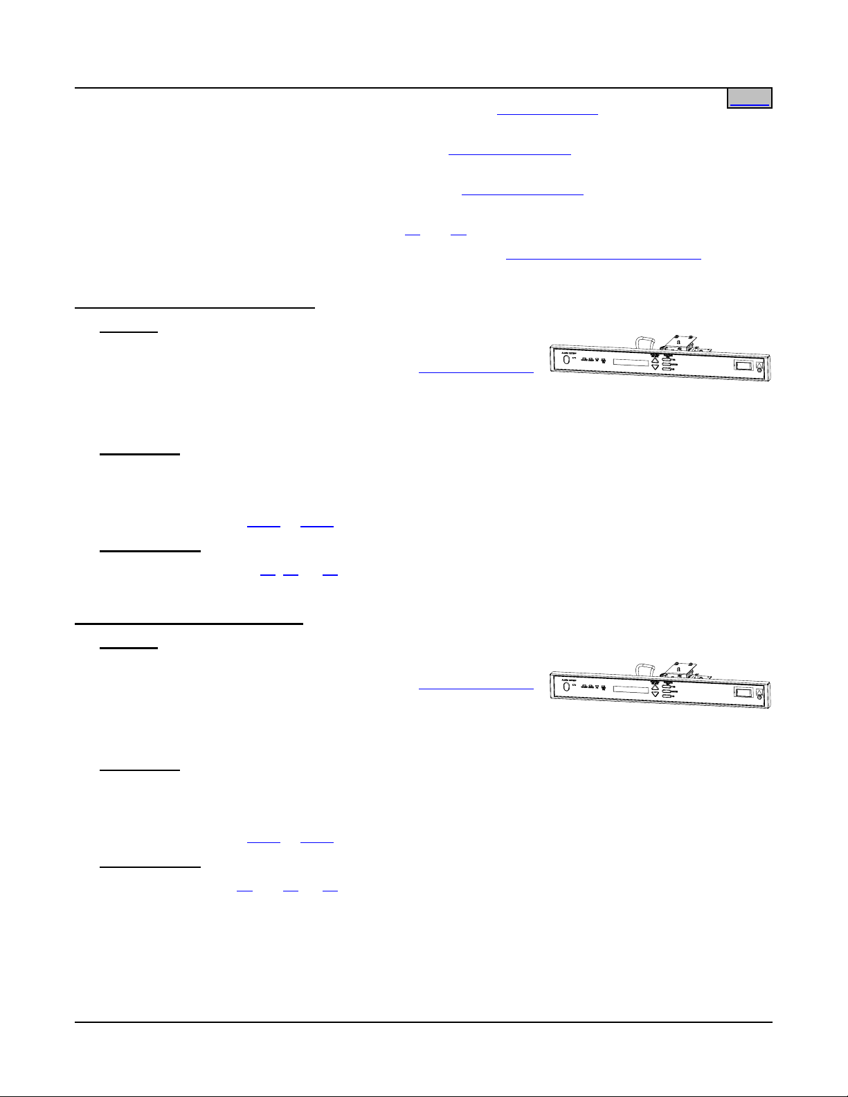
List 10: MCA (Standard Application)
Features
♦ Provides one standard application Meter-Control-Alarm (MCA)
assembly (Configuration No. 534876). Refer to
SPECIFICATIONS
for a description of MCA functions.
♦ Alarms: Major, Minor, High Voltage #1, High Voltage #2, Battery on Discharge, 50% Battery On
Discharge, AC Fail, MCA Audible, Test/Equalize Mode.
Restrictions
Only one (1) MCA per power system is required.
Mounts in the Main Bay Distribution Cabinet.
Cannot be ordered with
Ordering Notes
List 2 or List 5.
1) Order one (1) List 10,
11, 12, or 13 as required per power system.
List 11: MCA (Special Application)
Features
♦ Provides one special application Meter-Control-Alarm (MCA)
assembly (Configuration No. 534877). Refer to
SPECIFICATIONS
for a description of MCA functions.
♦ Alarms: Major, Minor, High Voltage #1, Rectifier Module Fail
Major, Battery On Discharge, Rectifier Module Fail Minor, AC Fail, MCA Audible, Fuse/Circuit Breaker.
Restrictions
Only one (1) MCA per power system is required.
Mounts in the Main Bay Distribution Cabinet.
Cannot be ordered with
Ordering Notes
1) Order one (1) List
List 2 or List 5.
10, 11, 12, or 13 as required per power system.
Page 19 of 123
This document is property of Emerson Network Power, Energy Systems, North America, Inc. and contains confidential and proprietary information owned by Emerson Network Power, Energy
Systems, North America, Inc. Any copying, use, or disclosure of it without the written permission of Emerson Network Power, Energy Systems, North America, Inc. is strictly prohibited.
Page 20
SAG581126000 System Application Guide
Issue AD, November 23, 2009 Spec. No. 581126000 (Model 700
NVBA)
Home
List 12: MCA (Special Application)
Features
♦ Provides one special application Meter-Control-Alarm (MCA)
assembly (Configuration No. 534878). Refer to
SPECIFICATIONS
for a description of MCA functions.
♦ Alarms: Major, Minor, High Voltage #1, MCA Fail, Battery on Discharge, Very Low Voltage, AC Fail,
Fuse/Circuit Breaker, Rectifier Module Fail.
Restrictions
Only one (1) MCA per power system is required.
Mounts in the Main Bay Distribution Cabinet.
Cannot be ordered with
Ordering Notes
1) Order one (1) List
List 2 or List 5.
10, 11, 12, or 13 as required per power system.
List 13: MCA (Special Application)
Features
♦ Provides one special application Meter-Control-Alarm (MCA)
assembly (Configuration No. 534879). Refer to
SPECIFICATIONS
for a description of MCA functions.
♦ Alarms: Major, Minor, Test/Equalize 2, Fuse/Circuit Breaker, Battery on Discharge, 50% Battery On
Discharge, AC Fail, Low Voltage Disconnect, Test/Equalize 1.
Restrictions
Only one (1) MCA per power system is required.
Mounts in the Main Bay Distribution Cabinet.
Cannot be ordered with
Ordering Notes
1) Order one (1) List
List 2 or List 5.
10, 11, 12, or 13 as required per power system.
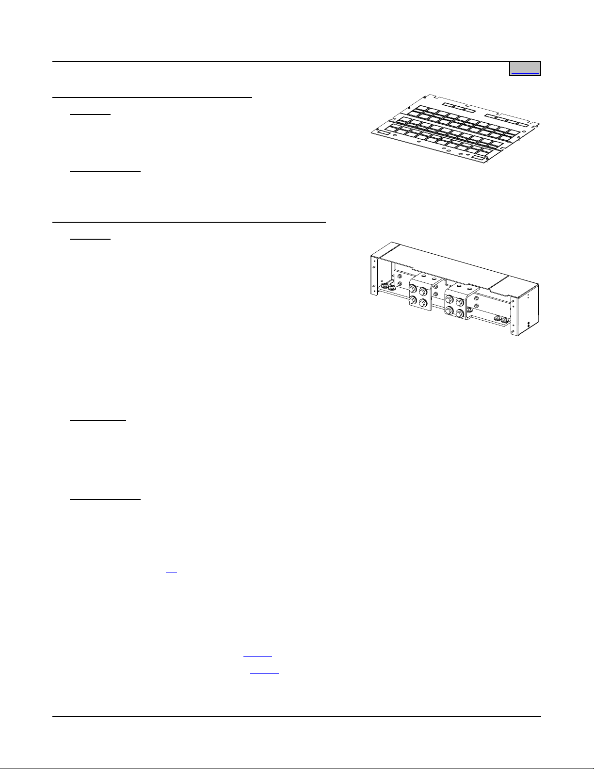
List 21: One-Row Distribution Cabinet
Features
♦ Accepts one (1) Distribution Bus Panel.
♦ Rated for up to 500 amperes of distribution (960 amperes when equipped
with
List ND).
♦ Available for use in
5List 1 and List 5 bays.
♦ One (1) Quad Shunt circuit card (P/N 507431) is provided with each
distribution cabinet. This circuit card can monitor up to four (4) system
distribution load shunts. All shunt cards interface with the MCA for system
distribution load current monitoring.
♦ A Low Voltage Disconnect (LVD) circuit card (P/N 509477) is provided in each Distribution Cabinet that…
¾ Contains one or more distribution rows that are equipped with a low voltage disconnect contactor, or
Page 20 of 123
This document is property of Emerson Network Power, Energy Systems, North America, Inc. and contains confidential and proprietary information owned by Emerson Network Power, Energy
Systems, North America, Inc. Any copying, use, or disclosure of it without the written permission of Emerson Network Power, Energy Systems, North America, Inc. is strictly prohibited.
Page 21
System Application Guide SAG581126000
Spec. No. 581126000 (Model 700
¾ Controls a Low Voltage Battery Disconnect (LVBD) contactor located in an associated
NVBA) Issue AD, November 23, 2009
Home
Battery Stand.
The LVD circuit card provides three separate control circuits. Each control circuit can be programmed,
through the MCA, with its own disconnect voltage setpoint and one global reconnect setpoint. One LVD
circuit card can control up to four (4) contactors. Any contactor can be controlled by any of the three
control circuits on the card by setting of user-selectable switches.
Where more than one Distribution Cabinet contains an LVD control circuit card, the control circuits on all
LVD circuit cards can be set to any of the three MCA-controlled disconnect setpoints independently with
user-selectable switches.
Each of the three control circuits on any LVD card consists of two individual battery voltage monitors, both
of which must sense low system voltage before disconnection can occur. This redundancy prevents a
control circuit failure from unnecessarily disconnecting loads or batteries.
The user can set the low voltage disconnect circuits for either automatic or manual recon ne ct.
¾ Automatic Reconnect: When system bus voltage recove rs to a preset adjustable value, the low
voltage disconnect circuits automatically reconnect the loads (or battery) to the system bus.
¾ Manual Reconnect: When system bus voltage ha s recovered to a preset adjustable value, the user
must issue a command via the MCA to reconnect loads (or battery) to the system bus.
A local switch provided in each Distribution Cabinet can be set to inhibit LVD operation for adjustment,
maintenance, and repair purposes. A local indicator illuminates when the low voltage disconnect circuit has
been inhibited. LVD operation is not inhibited in any other Distribution Cabinets in the power system.
Restrictions
Not available for
Cannot be ordered with
Ordering Notes
1) Order one (1) Distribution Bus Panel for each List 21 per '
2) Order fuses and/or circuit breakers, as required, per '
List 2 bays (no inter-bay busbar landings available).
List 1 if it is to be used with a List 2.
Distribution Bus Arrangements'.
Distribution Devices' under ACCESSORY
DESCRIPTIONS.
3) Order input and load distribution lugs, as required, per '
Wiring Components' under ACCESSORY
DESCRIPTIONS.
List 22: Two-Row Distribution Cabinet
Features
♦ Accepts up to two (2) Distribution Bus Panels.
♦ Rated for up to 1000 amperes of distribution.
♦ Available for use in
List 1 and List 5 bays.
♦ See also the description of the Quad Shunt circuit card under List
21
features.
♦ See also the description of the Low Voltage Disconnect circuit card under
21 features.
List
Restrictions
Not available for
This document is property of Emerson Network Power, Energy Systems, North America, Inc. and contains confidential and proprietary information owned by Emerson Network Power, Energy
Systems, North America, Inc. Any copying, use, or disclosure of it without the written permission of Emerson Network Power, Energy Systems, North America, Inc. is strictly prohibited.
List 2 bays (no inter-bay busbar landings available).
Page 21 of 123
Page 22
SAG581126000 System Application Guide
Issue AD, November 23, 2009 Spec. No. 581126000 (Model 700
Cannot be ordered with List 1 if it is to be used with a List 2.
NVBA)
Home
Ordering Notes
1) Order up to two (2) Distribution Bus Panels for each List 22 per '
2) Order fuses and/or circuit breakers, as required, per '
Distribution Devices' under ACCESSORY
DESCRIPTIONS.
3) Order input and load distribution lugs, as required, per '
Wiring Components' under ACCESSORY
DESCRIPTIONS.
List 23: Three-Row Distribution Cabinet
Features
♦ Accepts up to three (3) Distribution Bus Panels.
♦ Rated for up to 1500 amperes of distribution.
♦ Available for use in
List 1, List 2, and List 5 bays.
♦ See also the description of the Quad Shunt circuit card under List
features.
♦ See also the description of the Low Voltage Disconnect circuit card under
21 features.
List
Ordering Notes
1) Order up to three (3) Distribution Bus Panels for each List 23 per '
Distribution Bus Arrangements'.
21
Distribution Bus Arrangements'.
2) Order fuses and/or circuit breakers, as required, per '
Distribution Devices' under ACCESSORY
DESCRIPTIONS.
3) Order input and load distribution lugs, as required, per '
Wiring Components' under ACCESSORY
DESCRIPTIONS.
List 24: Four-Row Distribution Cabinet
Features
♦ Accepts up to four (4) Distribution Bus Panels.
♦ Rated for up to 2000 amperes of distribution.
♦ Available for use in
List 1, List 2, and List 5 bays.
♦ See also the description of the Quad Shunt circuit card under List
features.
♦ See also the description of the Low Voltage Disconnect circuit card under
21 features.
List
Ordering Notes
1) Order up to four (4) Distribution Bus Panels for each List 24 per
Distribution Bus Arrangements'.
'
2) Order fuses and/or circuit breakers, as required, per '
Distribution Devices'
under ACCESSORY DESCRIPTIONS.
21
3) Order input and load distribution lugs, as required, per '
Wiring
Components' under ACCESSORY DESCRIPTIONS.
Page 22 of 123
This document is property of Emerson Network Power, Energy Systems, North America, Inc. and contains confidential and proprietary information owned by Emerson Network Power, Energy
Systems, North America, Inc. Any copying, use, or disclosure of it without the written permission of Emerson Network Power, Energy Systems, North America, Inc. is strictly prohibited.
Page 23
System Application Guide SAG581126000
Spec. No. 581126000 (Model 700
NVBA) Issue AD, November 23, 2009
Home
List 29: Top Shield for Distribution Cabinet
Features
♦ Plastic shield covers all wiring access openings in top of
Distribution Cabinet. Individual cutouts can be removed for
wiring as required for specific installation.
Ordering Notes
1) Where closed top cover is required, order one (1) List 29 for each List
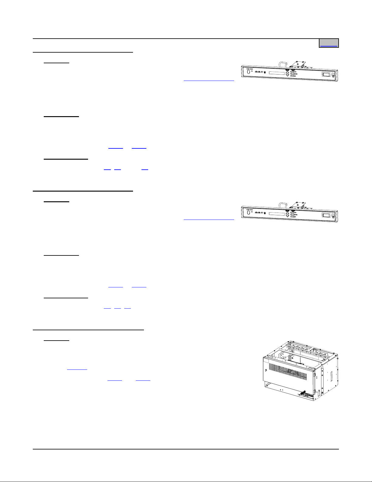
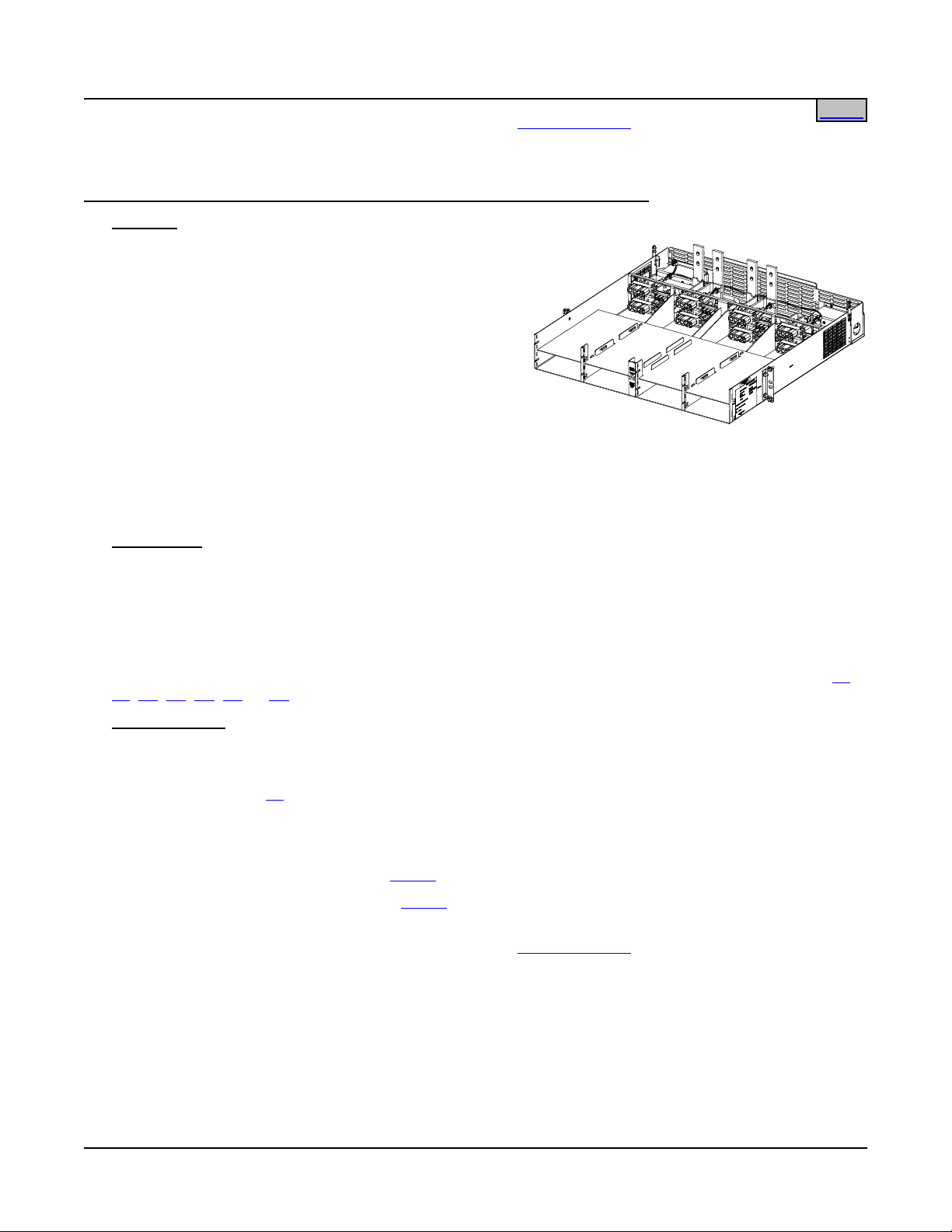
List 30: Module Mounting Assembly Interface Components
Features
♦ Provides components to add one (1) Module Mounting
Assembly (Spec. No. 588705101, 588705102, 588705103, or
588705104) to a Main or Supplemental Bay.
♦ The separately ordered Module Mounting Assembly can
consist of one (1), two (2), three (3), or four (4) factory
interconnected 8-position Module Mounting Shelves. Each
Module Mounting Shelf in a Module Mounting Assembly
provides eight (8) mounting positions for Rectifier Modules
(PCUs). When the Module Mounting Shelf is equipped with a DC-DC Converter Option Kit, the four (4)
middle positions will accept either Rectifier Modules (PCUs) or +24V/-48V DC-DC Converter Modules.
Note that Supplemental Bays CANNOT have Converter Modules.
21, 22, 23, and 24 ordered.
♦ Refer to Power Data Sheet PD588705100/PD588705101/PD588705102/PD588705103/PD588705104 for
Module Mounting Assembly information.
Restrictions
Factory installed only on the Distribution Cabinet.
Includes 'Module Mounting Assembly-to-Power System/Distribution Cabinet' intercon nect components only.
The Module Mounting Assembly must be ordered separately.
Each bay can be equipped with a maximum of one (1) Module Mounting Assembly.
Ordering Notes
1) Order one (1) List 30 per bay, regardless of the number of module mounting positions required (32
positions maximum per bay).
2) Order a Module Mounting Assembly per Power Data Sheet
PD588705101/PD588705102/PD588705103/PD588705104 as required.
3) Order one (1) List
60 (DC-DC Converter Option Kit) for each 8-position Module Mounting Shelf in which
DC-DC Converters are required. Note that some Module Mounting Assemblies consist of multiple
8-position Module Mounting Shelves. The kit permits the middle four (4) positions in an 8-position Module
Mounting Shelf to accept DC-DC Converter Modules or Rectifier Modules (PCUs). List 60 is factory
installed within the 8-position Module Mounting Shelf. List 60 kits will be installed starting with bottom
8-position Module Mounting Shelf in the Module Mounting Assembly and working up. Note that
Supplemental Bays CANNOT have Converter Modules.
4) Order Rectifier Modules (PCUs) per
5) Order DC-DC Converter Modules per
List 50 as required.
List 62 as required.
Note that Supplemental Bays CANNOT have Converter Modules.
Page 23 of 123
This document is property of Emerson Network Power, Energy Systems, North America, Inc. and contains confidential and proprietary information owned by Emerson Network Power, Energy
Systems, North America, Inc. Any copying, use, or disclosure of it without the written permission of Emerson Network Power, Energy Systems, North America, Inc. is strictly prohibited.
Page 24
SAG581126000 System Application Guide
Issue AD, November 23, 2009 Spec. No. 581126000 (Model 700
6) Order a Module Mounting Position Blank Cover Panel, Part No. 540959, for each empty module
NVBA)
Home
mounting position in the system.
List 31: Field Expansion Kit: One (1) 8-Position Module Mounting Assembly
Features
♦ Provides one (1) Spec No. 588705100 Module
Mounting Assembly and components required for field
installation in an existing Power System that has eight
(8) to twenty-four (24) positions.
♦ Included are busbars for connecting rectifier output to
the main system bus, and cables for connecting
DC-DC Converter output to the appropriate dual
voltage bus distribution panel assembly (if using
converters).
♦ The Module Mounting Shelf provides eight (8)
mounting positions for Rectifier Modules (PCUs). When the shelf is equipped with a DC-DC Converter
Option Kit, the four (4) middle positions will accept either Rectifier Modules (PCUs) or +24V/-48V DC-DC
Converter Modules. Note that Supplemental Bays CANNOT have Converter Modules.
♦ Refer to Power Data Sheet PD588705100 for more information.
Restrictions
For field installation only.
Maximum number of List 31 that can be installed in a power bay is one (1).
Original system must have a Module Mounting Assembly (up to twenty-four [24] positions).
Cannot be used in a power bay equipped with a Spec No. 588705104 Module Mounting Assembly.
Converter Modules must be used in conjunction with a dual voltage bus distribution panel assembly (List
JB, JC, JD, KA, LB, or LC). Note that Supplemental Bays CANNOT have Converter Modules.
Ordering Notes
1) For a bay equipped with Spec. No. 588705101 List 1, Spec. No. 588705102 List 1, or Spec. No.
588705103 List 1, order one (1) List 31.
2) Order one (1) List
60 (DC-DC Converter Option Kit) for each List 31 requiring DC-DC Converters. The kit
permits the middle four (4) positions in the 8-position Module Mounting Shelf to accept DC-DC Converter
Modules or Rectifier Modules (PCUs). List 60 is factory installed within the 8-position Module Mounting
Shelf in the assembly. Note that Supplemental Bays CANNOT have Converter Modules.
3) Order Rectifier Modules (PCUs) per
4) Order DC-DC Converter Modules per
List 50 as required.
List 62 as required.
Note that Supplemental Bays CANNOT have Converter Modules.
5) Order a Module Mounting Position Blank Cover Panel,
Part No. 540959, for each empty module mounting
position in the assembly.
JA,
Page 24 of 123
This document is property of Emerson Network Power, Energy Systems, North America, Inc. and contains confidential and proprietary information owned by Emerson Network Power, Energy
Systems, North America, Inc. Any copying, use, or disclosure of it without the written permission of Emerson Network Power, Energy Systems, North America, Inc. is strictly prohibited.
Page 25
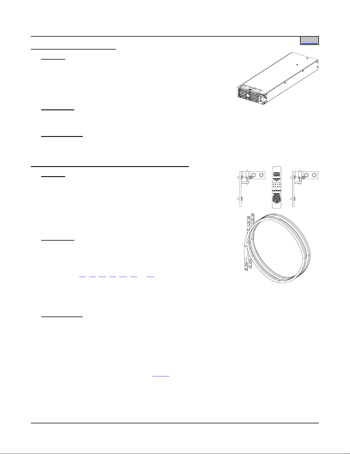
System Application Guide SAG581126000
Spec. No. 581126000 (Model 700
NVBA) Issue AD, November 23, 2009
Home
List 50: Rectifier Module (PCU)
Features
♦ Provides one (1) Model R24-2500, Spec. No. 1R242500, Rectifier
Module (PCU).
♦ Refer to Power Data Sheet
PD588705100/PD588705101/PD588705102/PD588705103/
PD588705104 for more information.
Restrictions
For use in Spec. No. 588705100, 588705101, 588705102, 588705103, or 588 705104 Module Mounting
Assemblies.
Ordering Notes
1) Order as required.
List 60: DC-DC Converter Option Interface Component Kit
Features
♦ Provides components to add DC-DC Converter capability to one (1)
8-position Module Mounting Shelf in a Module Mounting Assembly.
With one (1) List 60 installed, the four middle mounting positions in an
8-position Module Mounting Shelf in the Module Mounting Assembly
will accept DC-DC Converters or Rectifier Modules (PCUs).
♦ Includes cables for connection of converter output to a dual voltage
bus distribution panel assembly.
Restrictions
MUST be factory installed only.
CANNOT be used in Supplemental Bays.
Must be used in conjunction with a dual voltage bus distribution panel
assembly (List
JA, JB, JC, JD, KA, LB, or LC). Up to two (2) converter kits
can be used with a List JA, JB, JC, JD, LB, or LC. Up to four (4) converter
kits can be used with a List KA.
Total rectifier output power available for customer loads is reduced by the input power of each DC-DC
Converter Module installed.
Ordering Notes
1) Order one (1) List 60 (DC-DC Converter Option Kit) for each 8-position Module Mounting Shelf in which
DC-DC Converters are required (see restrictions above). Note that some Module Mounting Assemblies
consist of multiple 8-position mounting shelves. The kit permits the middle four (4) positions in an
8-position Module Mounting Shelf to accept DC-DC Converter Modules or Rectifier Modules (PCUs). List
60 is factory installed within the 8-position Module Mounting Shelf. Multiple List 60 kits will be installed
starting with bottom 8-position Module Mounting Shelf in the Module Mounting Assembly and working up.
Note that Supplemental Bays CANNOT have Converter Modules.
2) Order up to four (4) converter modules (
List 62) for each List 60 ordered.
Page 25 of 123
This document is property of Emerson Network Power, Energy Systems, North America, Inc. and contains confidential and proprietary information owned by Emerson Network Power, Energy
Systems, North America, Inc. Any copying, use, or disclosure of it without the written permission of Emerson Network Power, Energy Systems, North America, Inc. is strictly prohibited.
Page 26
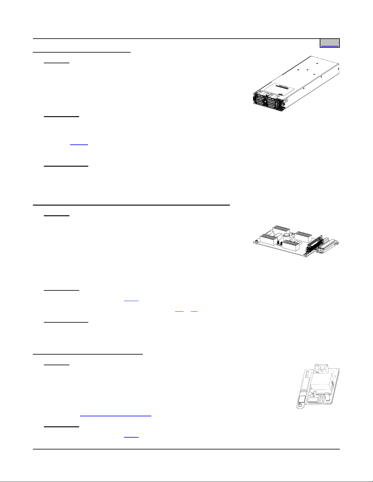
SAG581126000 System Application Guide
Issue AD, November 23, 2009 Spec. No. 581126000 (Model 700
NVBA)
Home
List 62: DC-DC Converter Module
Features
♦ Provides one (1) Model C24/48-1500, Spec. No. 1C24481500, DC-DC
Converter Module.
♦ Refer to Power Data Sheet
PD588705100/PD588705101/PD588705102/PD588705103/
PD588705104 for more information.
Restrictions
For use in Spec. No. 588705100, 588705101, 588705102, 588705103, or 588 705104 Module Mounting
Assemblies.
Requires
List 60.
Supplemental Bays CANNOT have Converter Modules.
Ordering Notes
1) Order as required. Each 8-position Module Mounting Shelf holds up to four (4) DC-DC Converter
Modules when equipped with a DC-DC Converter Option Kit.
List 71: Optional Audible Alarm and Alarm Termination Circuit Card
Features
♦ Provides an Audible Alarm and Alarm Termination circuit card (P/N
509539). This circuit card is interconnected to the MCA and (via relays
on the circuit card) to external converter major and minor alarm circuits
(if converters are furnished). The circuit card provides spring-clamp
type terminals for connection of customer wiring to the MCA external
alarm circuits in lieu of the standard alarm cable.
♦ Includes a local audible alarm-sounding device connected to the external audible alarm contacts. The
audible alarm can be silenced locally.
Restrictions
Must be located in Main Bay (
Audible alarm is inoperative when used with List
Ordering Notes
List 1) only.
12 or 13 MCA (no audible alarm relay contacts available).
1) Order per site requirements.
List 72: MCA Interface Modem Option
Features
♦ Provides a 2400 bits/s Modem circuit card, Spec. No. 486781300, plus associated
hardware.
♦ This option plugs into the MCA.
♦ Allows MCA interface via a modem port.
♦ See also
Restrictions
Must be located in Main Bay (
WinLink Software (List 73).
List 1) only.
Page 26 of 123
This document is property of Emerson Network Power, Energy Systems, North America, Inc. and contains confidential and proprietary information owned by Emerson Network Power, Energy
Systems, North America, Inc. Any copying, use, or disclosure of it without the written permission of Emerson Network Power, Energy Systems, North America, Inc. is strictly prohibited.
Page 27
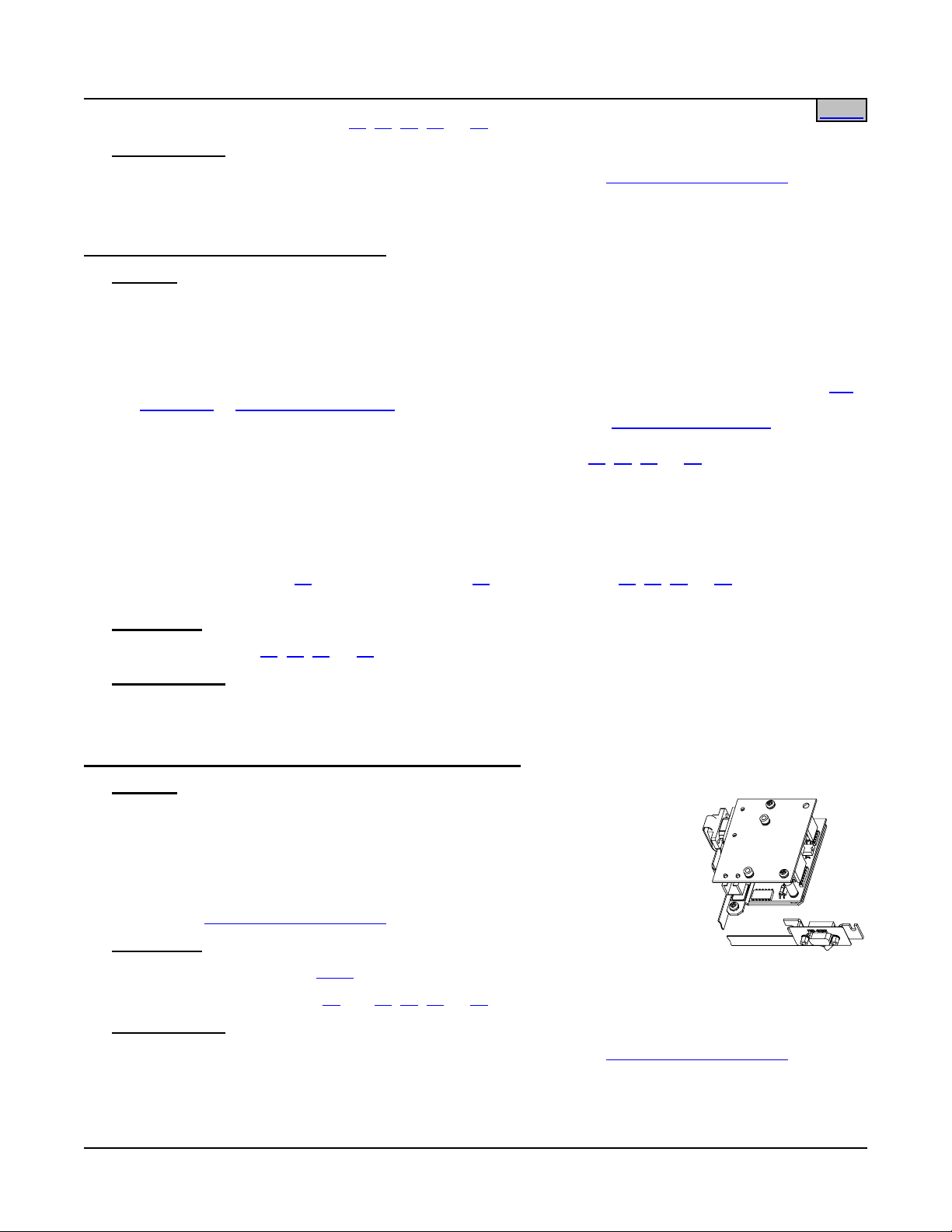
System Application Guide SAG581126000
Spec. No. 581126000 (Model 700
Only one interface option (List 72, 74, 75, 76, 77, or 78) can be installed.
NVBA) Issue AD, November 23, 2009
Home
Ordering Notes
1) Order this option for each Power System (MCA) to be accessed via
6WinLink Software (List 73) via
modem.
List 73: MCA Interface WinLink Software
Features
♦ Provides Spec. No. 041182000 (WinLink Software).
♦ WinLink Software provides the user the ability to remotely communicate with multiple Power Systems
equipped with an MCA. Only one Power System (MCA) can be remotely connected at a time. This
allows a user to remotely monitor, control, and adjust the Power System via WinLink. Remote
communications can be done over dial-up phone lines when the Power System is equipped with the
72 Modem or List 74 RS-232/Modem MCA Interface Option. Remote communications can be done via
an RS-232 connection when the Power System is equipped with the
6List 74 RS-232/Modem MCA
Interface Option. Remote communications can be done via a TCP/IP connection when the Power
System is equipped with the Ethernet MCA Interface Option (List
75, 76, 77, or 78).
♦ With WinLink Software, most tasks accomplished via the Power System MCA local interface pad can be
done remotely. This includes alarm monitoring, voltage/current monitoring, and adjustment of alarm and
control circuits.
♦ Runs under Windows 98, ME, NT 4.0, 2000, or XP.
♦ See also Modem (List
72), RS-232/Modem (List 74), or Ethernet (List 75, 76, 77, or 78) MCA Interface
Options.
List
Restrictions
Not required for Lists
Ordering Notes
75, 76, 77, or 78.
1) Only one List 73 required for each computer installation.
List 74: MCA Interface Combination Modem/RS-232 Option
Features
♦ Provides a Modem circuit card, an RS-232 circuit card, and associated
mounting hardware.
♦ This option plugs into the MCA.
♦ Allows MCA interface via an RS-232 and Modem port.
♦ See also
Restrictions
Must be located in Main Bay (
Only one interface option (List
Ordering Notes
WinLink Software (List 73).
List 1) only.
72, 74, 75, 76, 77, or 78) can be installed.
1) Order this option for each Power System (MCA) to be accessed via
modem or RS-232.
6WinLink Software (List 73) via
Page 27 of 123
This document is property of Emerson Network Power, Energy Systems, North America, Inc. and contains confidential and proprietary information owned by Emerson Network Power, Energy
Systems, North America, Inc. Any copying, use, or disclosure of it without the written permission of Emerson Network Power, Energy Systems, North America, Inc. is strictly prohibited.
Page 28
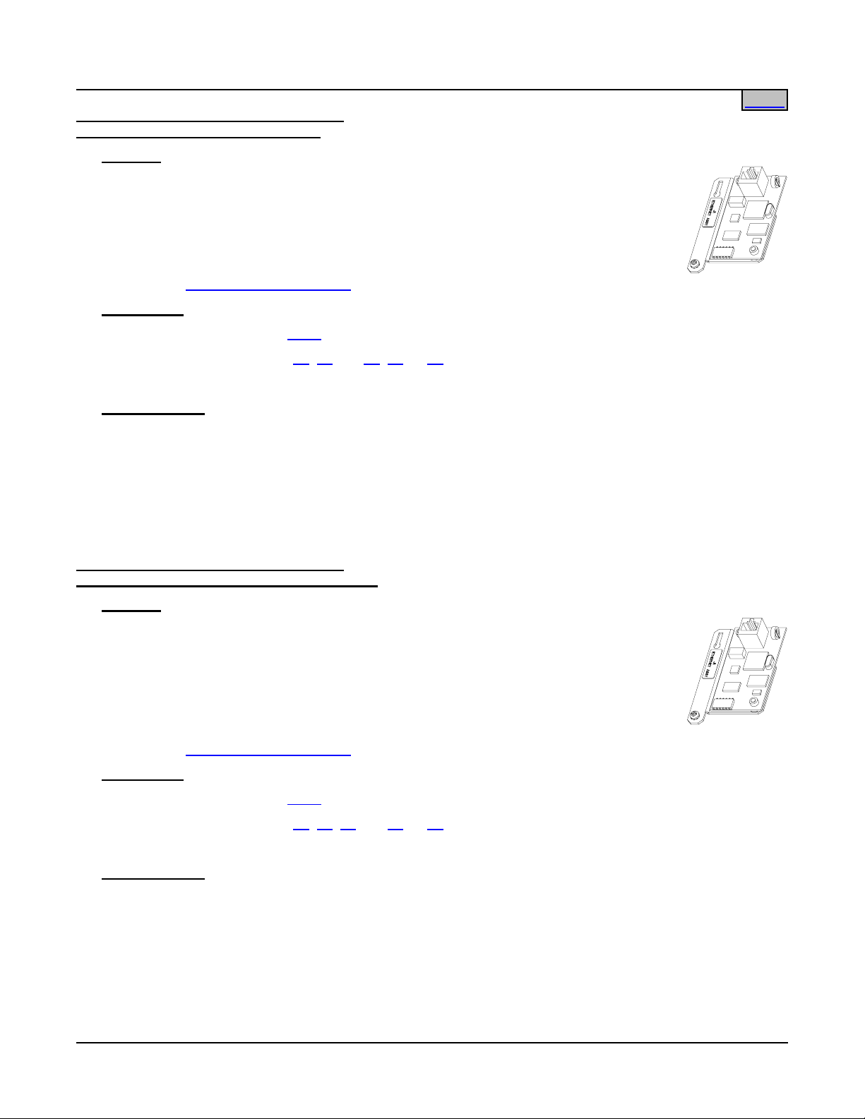
SAG581126000 System Application Guide
Issue AD, November 23, 2009 Spec. No. 581126000 (Model 700
NVBA)
Home
List 75: MCA Interface Ethernet Option: WinLink Compatible + Web Interface
Features
♦ Provides an Ethernet circuit card (P/N 524541) and associated mounting hardware.
♦ Ethernet circuit card is WinLink Compatible and provides a Web Interface.
♦ This option plugs into the MCA.
♦ Allows MCA interface via an Ethernet port.
♦ See also
Restrictions
Must be located in Main Bay (
Only one interface option (List
WinLink Software (List 73).
List 1) only.
72, 74, 75, 76, 77, or 78) can be installed.
The Ethernet card requires an MCA with firmware version 5.2.0 or later.
Ordering Notes
1) Order this option for each Power System (MCA) to be accessed via
WEB Interface.
2) Order optional Front Access Ethernet Connector Kit P/N 525110, as required. This incl udes an RJ45
connector, mounting bracket, and jumper that mounts in the cutout provided on the front of the MCA
Panel.
3) WinLink Software (List 73) will operate with List 75 but is not required. Internal WEB Pages are preferred.
List 76: MCA Interface Ethernet Option: WinLink Compatible + Web Interface + SNMP
Features
♦ Provides an Ethernet circuit card (P/N 524541) and associated mounting hardware.
♦ Ethernet circuit card is WinLink Compatible, provides a Web Interface, and provides
SNMP.
♦ This option plugs into the MCA.
♦ Allows MCA interface via an Ethernet port.
♦ See also
Restrictions
Must be located in Main Bay (
Only one interface option (List
WinLink Software (List 73).
List 1) only.
72, 74, 75, 76, 77, or 78) can be installed.
The Ethernet card requires an MCA with firmware version 5.2.0 or later.
Ordering Notes
1) Order this option for each Power System (MCA) to be accessed via WEB Interface.
2) Order optional Front Access Ethernet Connector Kit P/N 525110, as required. This incl udes an RJ45
connector, mounting bracket, and jumper that mounts in the cutout provided on the front of the MCA
Panel.
3) WinLink Software (List 73) will operate with List 76 but is not required. Internal WEB Pages are preferred.
Page 28 of 123
This document is property of Emerson Network Power, Energy Systems, North America, Inc. and contains confidential and proprietary information owned by Emerson Network Power, Energy
Systems, North America, Inc. Any copying, use, or disclosure of it without the written permission of Emerson Network Power, Energy Systems, North America, Inc. is strictly prohibited.
Page 29
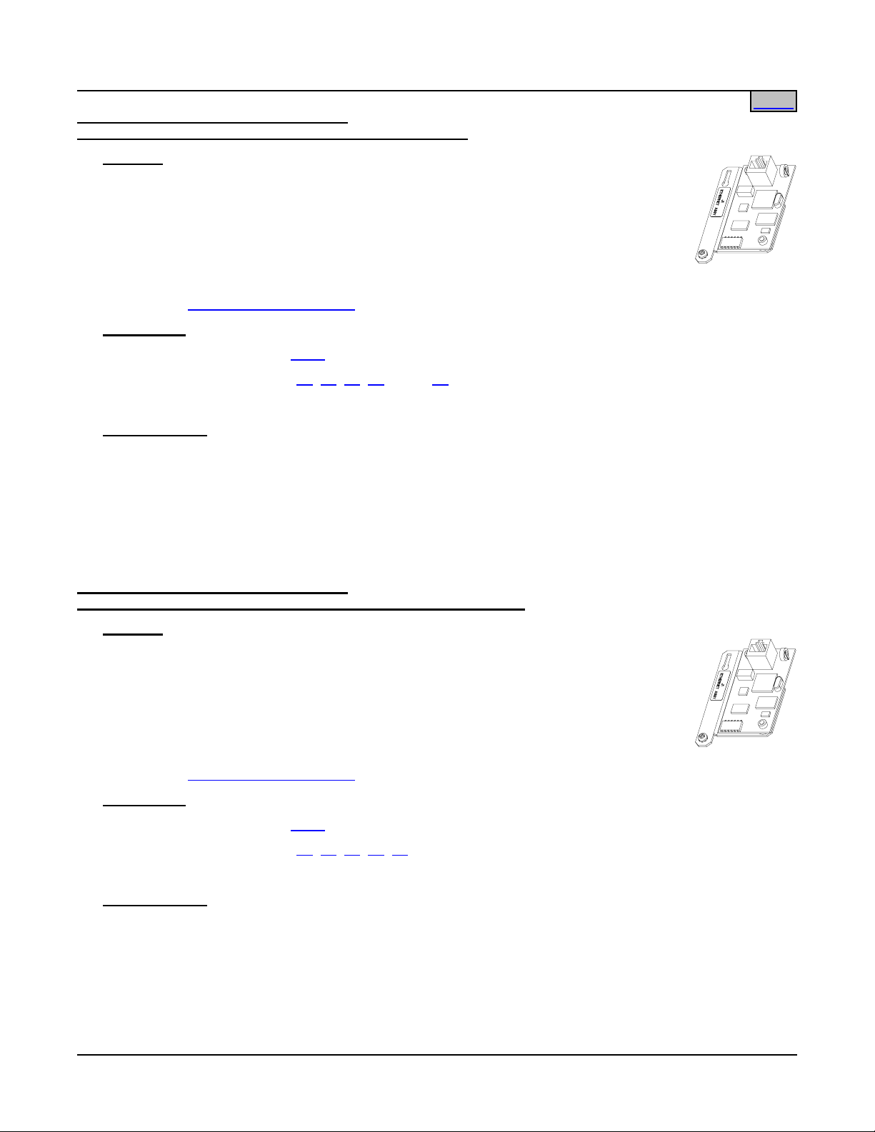
System Application Guide SAG581126000
Spec. No. 581126000 (Model 700
NVBA) Issue AD, November 23, 2009
Home
List 77: MCA Interface Ethernet Option: WinLink Compatible + Web Interface + Battery Monitoring
Features
♦ Provides an Ethernet circuit card (P/N 524541) and associated mounting hardware.
♦ Ethernet circuit card is WinLink Compatible, provides a Web Interface, and provides
Battery Monitoring.
♦ This option plugs into the MCA.
♦ Allows MCA interface via an Ethernet port.
♦ See also
Restrictions
Must be located in Main Bay (
Only one interface option (List
WinLink Software (List 73).
List 1) only.
72, 74, 75, 76, 77, or 78) can be installed.
The Ethernet card requires an MCA with firmware version 5.2.0 or later.
Ordering Notes
1) Order this option for each Power System (MCA) to be accessed via WEB Interface.
2) Order optional Front Access Ethernet Connector Kit P/N 525110, as required. This incl udes an RJ45
connector, mounting bracket, and jumper that mounts in the cutout provided on the front of the MCA
Panel.
3) WinLink Software (List 73) will operate with List 77 but is not required. Internal WEB Pages are preferred.
List 78: MCA Interface Ethernet Option: WinLink Compatible + Web Interface + SNMP + Battery Monitoring
Features
♦ Provides an Ethernet circuit card (P/N 524541) and associated mounting hardware.
♦ Ethernet circuit card is WinLink Compatible, provides a Web Interface, provides
Battery Monitoring, and provides SNMP.
♦ This option plugs into the MCA.
♦ Allows MCA interface via an Ethernet port.
♦ See also
Restrictions
Must be located in Main Bay (
Only one interface option (List
WinLink Software (List 73).
List 1) only.
72, 74, 75, 76, 77, or 78) can be installed.
The Ethernet card requires an MCA with firmware version 5.2.0 or later.
Ordering Notes
1) Order this option for each Power System (MCA) to be accessed via WEB Interface.
2) Order optional Front Access Ethernet Connector Kit P/N 525110, as required. This incl udes an RJ45
connector, mounting bracket, and jumper that mounts in the cutout provided on the front of the MCA
Panel.
3) WinLink Software (List 73) will operate with List 78 but is not required. Internal WEB Pages are preferred.
Page 29 of 123
This document is property of Emerson Network Power, Energy Systems, North America, Inc. and contains confidential and proprietary information owned by Emerson Network Power, Energy
Systems, North America, Inc. Any copying, use, or disclosure of it without the written permission of Emerson Network Power, Energy Systems, North America, Inc. is strictly prohibited.
Page 30
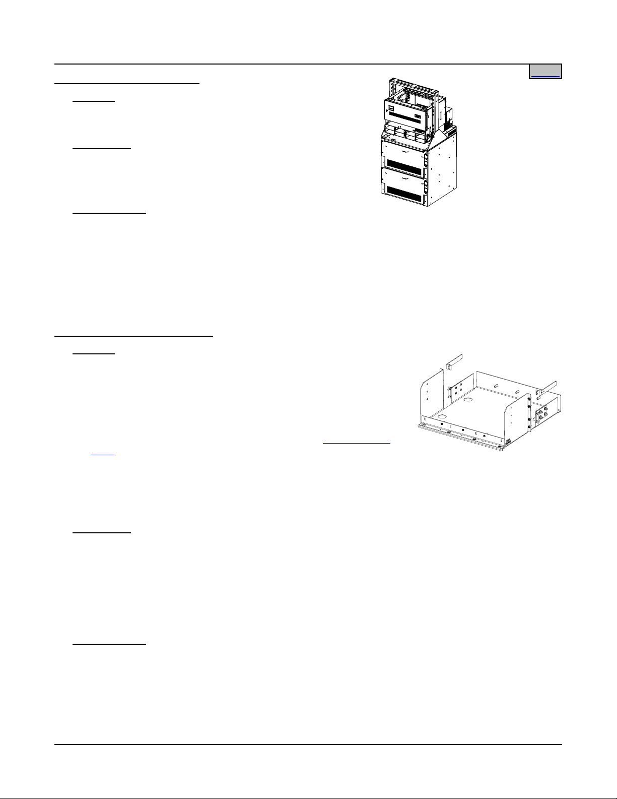
SAG581126000 System Application Guide
Issue AD, November 23, 2009 Spec. No. 581126000 (Model 700
List 92: Battery Stand System
NVBA)
Home
Features
♦ Complete battery stand platform, including monitoring
options. For more information, refer to SAG588810000.
Restrictions
There must be 1RU of space below the power system.
List 92 cannot be ordered with Lists 4, 93, RA, RB, RC, RD, or
RE.
Ordering Notes
1) Order as required. When List 92 is ordered as part of the
power system, the power system can be mounted in a relay
rack on top of the battery stand.
2) The system must be ordered in one of the following relay racks:
543151, 543152, 543153, 543154, 543155, 543156, 543157.
3) The system must be equipped with a rectifier shelf.
List 93: Battery Tray, Pre-Cabled
Features
♦ Provides one battery tray that mounts four (4) 12V front terminal VLRA
batteries. Batteries are configured as two (2) 24V strings per tray.
Battery cabling is factory-connected to Power System main bus.
Generic assembly of parts creating a List 92.
Battery stand (number of rows), relay rack (height),
shelf (number of positions), and distribution cabinet
(number of rows) can vary depending on configuration.
♦ Accepts various Valve Regulated Lead Acid (VLRA) batteries. See
Ordering Notes below.
♦ Tray dimensions are 21.3” wide X 22.4” deep. See '
List 93 (Battery
Tray)' under PHYSICAL SIZE INFORMATION for a typical battery tray
arrangement.
♦ Trays can be ordered with or without Battery Disconnect circuit breakers. When circuit breakers are
ordered, one is provided in the +24V lead of each battery string (2 circuit breakers per tray).
♦ Inter-battery spacer plates included.
Restrictions
Cannot be used with List RA, RB, RC, RD, RE, or 92.
Maximum number of List 93 per bay is four (4).
A single List 93 must mount at bottom of bay. Multiples of List 93 must mount starting at bottom of bay and
working upward.
Not a stand-alone battery system. Must be used as part of a power system that includes List 1, List 2 or List 5
with List 21, 22, 23, or 24 and List 30.
Ordering Notes
1) Order multiples of List 93 for more than one (1) battery tray. See Restrictions.
2) Order batteries separately. The following table lists batteries recommended for use with List 93.
Page 30 of 123
This document is property of Emerson Network Power, Energy Systems, North America, Inc. and contains confidential and proprietary information owned by Emerson Network Power, Energy
Systems, North America, Inc. Any copying, use, or disclosure of it without the written permission of Emerson Network Power, Energy Systems, North America, Inc. is strictly prohibited.
Page 31

System Application Guide SAG581126000
Spec. No. 581126000 (Model 700
NVBA) Issue AD, November 23, 2009
Home
Manufacturer* Model
Emerson
Network
Power
P/N
Rated 8-Hr.
Capacity
(Ah)
Dimension
W x L x H
(Inches)
Required
Tray
Spacing
Weight
per
battery
(lbs)
C&D TEL12-160F 140456 157 4.95 x 22.01 x 11.14 7U 115
C&D TEL12-180F -- 181 4.95 x 22.01 x 12.60 8U 131
Deka Unigy I 12AVR-150ET 122018 150 4.90 x 22.00 x 11.75 8U 115
Douglas DGS12-150F 125453 150 4.90 x 22.00 x 12.70 8U 137
Douglas DST12-170F -- 170.8 4.92 x 22.05 x 12.60 8U 129.6
Enersys
PowerSafe
12V155F 122010 155 4.92 x 22.09 x 12.44 8U 148
Fiamm 12FAT125 -- 125 4.96 x 21.97 x 10.67 7U 110.23
Fiamm 12FAT155 -- 155 4.96 x 21.97 x12.64 8U 132.25
GNB Marathon M12V125FT -- 125 4.90 x 22.00 x 11.15 7U 105
GNB Marathon M12V155FT 112795 155 4.90 x 22.00 x 11.15 7U 119
Northstar NSB170FT -- 167 4.92 x 22.05 x 12.60 8U 131
* See Battery Manufacturer Information located at the end of this document.
3) Specify rack spacing of 7U (12.25”) or 8U (14”) between trays and above top tray as required for battery
clearance. See table above.
4) Specify the batteries you intend to use with each List 93 ordered. Lugs for battery connections vary
according to the batteries to be installed. Battery cables will be lugged as shown in the following table.
The table is provided for reference only.
Battery Lug Kit Part Numbers
(Kit provides two lugs for one tray.)
Battery
Specified
Ordered Without
Circuit Breaker
Ordered With
Circuit Breaker
125A or Higher
Ordered With
Circuit Breaker
100A or Lower
C&D TEL12-160F 528235 528235 528234
C&D TEL12-180F 528235 528235 528234
Deka Unigy I 12AVR-150ET 528235 528235 528234
Douglas DGS12-150F
528237 528237 528236
Douglas DST12-170F 528235 528235 528234
Enersys PowerSafe 12V155F 528235 528235 528234
Fiamm 12FAT125 528235 528235 528234
Fiamm 12FAT155 528235 528235 528234
GNB Marathon M12V125FT 528235 528235 528234
GNB Marathon M12V155FT 528235 528235 528234
Northstar NSB170FT 528235 528235 528234
5) Specify with or without Battery Disconnect circuit breakers. Note: All List 93 trays in a bay will be
furnished with or without Battery Disconnect circuit breakers as specified for the first tray ordered.
Page 31 of 123
This document is property of Emerson Network Power, Energy Systems, North America, Inc. and contains confidential and proprietary information owned by Emerson Network Power, Energy
Systems, North America, Inc. Any copying, use, or disclosure of it without the written permission of Emerson Network Power, Energy Systems, North America, Inc. is strictly prohibited.
Page 32

SAG581126000 System Application Guide
Issue AD, November 23, 2009 Spec. No. 581126000 (Model 700
NVBA)
6) An assembly for connection of all List 93 is automatically added to the order. Part number depends on
system configuration.
7) If ordering List 93 with circuit breakers, order two (2) circuit breakers per List 93 from the following table.
Ampere
Rating
Electrical/Mechanical Trip
Part Number
1
(Black Handle) Electrical Trip2 (White Handle)
50 256694300 256694400
60 256694700 256694800
70 256695100 256695200
75 256695500 256695600
100 256695900 256696000
125 100765 100762
150 100763 100764
200 121810 121809
Circuit Breaker Alarm Operation:
1
Provides an alarm during an electrical or manual trip condition.
2
Provides an alarm during an electrical trip condition only.
Page 32 of 123
This document is property of Emerson Network Power, Energy Systems, North America, Inc. and contains confidential and proprietary information owned by Emerson Network Power, Energy
Systems, North America, Inc. Any copying, use, or disclosure of it without the written permission of Emerson Network Power, Energy Systems, North America, Inc. is strictly prohibited.
Page 33

System Application Guide SAG581126000
Spec. No. 581126000 (Model 700
NVBA) Issue AD, November 23, 2009
Home
List AA: Distribution Bus Module (P/N 509840) (24) Fuse/Circuit Breaker System Positions
Features
♦ Single Voltage Distribution (+24V)
♦ 500A Maximum Capacity
♦ (24) Load Distribution Fuse / Circuit Breaker Mounting Positions (3 to 100A TPS/TLS-Type Fu ses / 1 to
250A Bullet Nose Type Circuit Breakers), or accepts “
GMT Load Distribution Fuse Block Assembly Kit
(P/N 514432)”.
Restrictions
Can be installed in any bus position A-D (row 1-4) of a 1-, 2-, 3-, or 4-bus row cabinet.
Unless otherwise specified fuses and/or circuit breakers are mounted from left to right, starting with the
highest capacity and working to the lowest capacity.
125A, 150A, and 200A circuit breakers occupy two mounting positions. 250A circuit breakers occupy three
mounting positions.
Caution:
A circuit breaker or fuse with a rating greater than 150 amperes SHALL HAVE an empty
mounting position between it and any other overcurrent protective device.
Maximum size of wire to be connected to a single fuseholder or circuit breaker position is 2 AWG.
Ordering Notes
1) Order circuit breakers as required per
2) Order fuses as required per
Table 7.
Table 8.
Also order one (1) P/N 117201 bullet nose-type fuseholder per fuse ordered.
3) Order load lugs (two hole, 1/4” bolt clearance hole, 5/8” centers) as required for each distribution position
per Table
4) Order lug hardware kit,
9 or 11.
7P/N 520332, as required. Kit provides all hardware required to connect load and
ground lugs for four (4) positions of a bullet nose-type distribution assembly.
1/4-20 STUD, 48 PLACES
(CUSTOMER MUST SUPPLY ADDITIONAL HARDWARE)
GROUND
BUSBAR
3/4"
LOAD RETURN
5/8"
CONNECTIONS
LOAD
5/8"
CONNECTIONS
LOADS
1/4-20 THREADED HOLE, 48 PLACES
(CUSTOMER MUST SUPPLY LUG BOLTS
AND ADDITIONAL HARDWARE. BOLT LENGTH: 3/4")
Page 33 of 123
This document is property of Emerson Network Power, Energy Systems, North America, Inc. and contains confidential and proprietary information owned by Emerson Network Power, Energy
Systems, North America, Inc. Any copying, use, or disclosure of it without the written permission of Emerson Network Power, Energy Systems, North America, Inc. is strictly prohibited.
Page 34

SAG581126000 System Application Guide
Issue AD, November 23, 2009 Spec. No. 581126000 (Model 700
NVBA)
Home
List AB: Distribution Bus Module (P/N 428316100) (3) GJ/218 Circuit Breaker System Positions
Features
♦ Single Voltage Distribution (+24V)
♦ 500A Maximum Capacity
♦ (3) Load Distribution Circuit Breaker Mounting Positions
(100 to 600A GJ/218-Type) NOTE RESTRICTIONS
Restrictions
Can be installed in bus positions A-C (row 1-3) of a 1-, 2-, 3-, or 4-bus row cabinet. Cannot be installed in bus
position D (row 4) of a 4-bus row cabinet. See also
List AC for similar application in bus position D (row 4).
Panel is designed to mount circuit breakers in the following possible combinations:
(3) 100A to 250A
(1) 100A to 250A and (1) 300A or 400A
(1) 600A
Ordering Notes
1) Order circuit breakers and associated jumper kits as required per Table s
5 and 6.
2) Order load lugs (two hole, 3/8” bolt clearance hole, 1” centers) as required for each distribution position
per Table
GROUND
BUSBAR
10.
LOAD
CONNECTIONS
LOAD RETURN
CONNECTIONS
1.5"
3/8-16 CAPTIVE NUT, 12 PLACES
(CUSTOMER MUST SUPPLY LUG
BOLTS AND ADDITIONAL
HARDWARE. BOLT LENGTH: 1-1/4")
1"
1"
1"
1"
LOADS
Page 34 of 123
This document is property of Emerson Network Power, Energy Systems, North America, Inc. and contains confidential and proprietary information owned by Emerson Network Power, Energy
Systems, North America, Inc. Any copying, use, or disclosure of it without the written permission of Emerson Network Power, Energy Systems, North America, Inc. is strictly prohibited.
Page 35

System Application Guide SAG581126000
Spec. No. 581126000 (Model 700
NVBA) Issue AD, November 23, 2009
Home
List AC: Distribution Bus Module (P/N 507198) (3) GJ/218 Circuit Breaker System Positions
Features
♦ Single Voltage Distribution (+24V)
♦ 500A Maximum Capacity
♦ (3) Load Distribution Circuit Breaker Mounting Positions
(100 to 600A GJ/218-Type) NOTE RESTRICTIONS
Restrictions
For use in a 4-bus row cabinet only. Must be installed in bus position D (row 4). See also
List AB for similar
application in bus positions A-C (rows 1-3).
Panel is designed to mount circuit breakers in the following possible combinations:
(3) 100A to 250A
(1) 100A to 250A and (1) 300A or 400A
(1) 600A
Ordering Notes
1) Order circuit breakers and associated jumper kits as required per Table s
5 and 6.
2) Order load lugs (two hole, 3/8” bolt clearance hole, 1” centers) as required for each distribution position
per Table
GROUND
BUSBAR
10.
LOAD
CONNECTIONS
LOAD RETURN
CONNECTIONS
1.5"
3/8-16 CAPTIVE NUT, 12 PLACES
(CUSTOMER MUST SUPPLY LUG
BOLTS AND ADDITIONAL
HARDWARE. BOLT LENGTH: 1-1/4")
1"
1"
1"
1"
LOADS
Page 35 of 123
This document is property of Emerson Network Power, Energy Systems, North America, Inc. and contains confidential and proprietary information owned by Emerson Network Power, Energy
Systems, North America, Inc. Any copying, use, or disclosure of it without the written permission of Emerson Network Power, Energy Systems, North America, Inc. is strictly prohibited.
Page 36

SAG581126000 System Application Guide
Issue AD, November 23, 2009 Spec. No. 581126000 (Model 700
NVBA)
Home
List AD: Distribution Bus Module (P/N 509565) (8) GJ/218 Circuit Breaker System Positions (Upper Two Rows)
Features
♦ Single Voltage Distribution (+24V)
♦ 1,000A Maximum Capacity (500A per side)
♦ (8) Load Distribution Circuit Breaker Mounting Positions
(100 to 600A GJ/218-Type) NOTE RESTRICTIONS
Restrictions
Occupies two distribution rows.
For use in a 4-bus row cabinet only. Must be installed in bus positions C and D (rows 3 and 4). See also
List
AE for similar application in bus positions A and B (rows 1 and 3) or B and C (rows 2 and 3).
Panel is designed to mount circuit breakers in the following possible combi nations per side:
(4) 100A to 250A
(2) 100A to 250A and (1) 300A or 400A
(2) 300A or 400A
(1) 600A and (1) 100A to 250A
Unless otherwise specified circuit breakers are divided between the two sides, and are mounted from left to
right, starting with the highest capacity and working to the lowest capacity on each side.
Ordering Notes
1) Order circuit breakers and associated jumper kits as required per Table s
5 and 6.
2) Order load lugs (two hole, 3/8” bolt clearance hole, 1” centers) as required for each distribution position
per Table
10.
3/8-16 CAPTIVE NUT, 32 PLACES (CUSTOMER MUST PROVIDE LUG
LOAD CONNECTIONS
GROUND
BUSBAR
LOAD RETURN
CONNECTIONS
BOLTS AND ADDITIONAL HARDWARE. BOLT LENGTH: 1-1/4")
1-7/8"
1"
1"
LOADS
1"
Page 36 of 123
This document is property of Emerson Network Power, Energy Systems, North America, Inc. and contains confidential and proprietary information owned by Emerson Network Power, Energy
Systems, North America, Inc. Any copying, use, or disclosure of it without the written permission of Emerson Network Power, Energy Systems, North America, Inc. is strictly prohibited.
Page 37

System Application Guide SAG581126000
Spec. No. 581126000 (Model 700
NVBA) Issue AD, November 23, 2009
Home
List AE: Distribution Bus Module (P/N 509648) (8) GJ/218 Circuit Breaker System Positions (Lo wer Two Rows)
Features
♦ Single Voltage Distribution (+24V)
♦ 1,000A Maximum Capacity (500A per side)
♦ (8) Load Distribution Circuit Breaker Mounting Positions
(100 to 600A GJ/218-Type) NOTE RESTRICTIONS
Restrictions
Occupies two distribution rows.
For use in a 2-, 3-, or 4-bus row cabinet. Must be installed in bus positions A and B (rows 1 and 2), or B and
C (rows 2 and 3). See also
List AD for similar application in bus positions C and D (rows 3 and 4).
Panel is designed to mount circuit breakers in the following possible combi nations per side:
(4) 100A to 250A
(2) 100A to 250A and (1) 300A or 400A
(2) 300A or 400A
(1) 600A and (1) 100A to 250A
Unless otherwise specified circuit breakers are divided between the two sides, and are mounted from left to
right, starting with the highest capacity and working to the lowest capacity on each side.
Ordering Notes
1) Order circuit breakers and associated jumper kits as required per Table s
5 and 6.
2) Order load lugs (two hole, 3/8” bolt clearance hole, 1” centers) as required for each distribution position
per Table
10.
3/8-16 CAPTIVE NUT, 32 PLACES (CUSTOMER MUST PROVIDE LUG
LOAD CONNECTIONS
GROUND
BUSBAR
LOAD RETURN
CONNECTIONS
BOLTS AND ADDITIONAL HARDWARE. BOLT LENGTH: 1-1/ 4" )
1-7/8"
1"
1"
LOADS
1"
Page 37 of 123
This document is property of Emerson Network Power, Energy Systems, North America, Inc. and contains confidential and proprietary information owned by Emerson Network Power, Energy
Systems, North America, Inc. Any copying, use, or disclosure of it without the written permission of Emerson Network Power, Energy Systems, North America, Inc. is strictly prohibited.
Page 38

SAG581126000 System Application Guide
Issue AD, November 23, 2009 Spec. No. 581126000 (Model 700
NVBA)
Home
List AG: Distribution Bus Module (P/N 514010) (2) TPH Fuse System Positions
Features
♦ Single Voltage Distribution (+24V)
♦ 500A Maximum Capacity
♦ (2) Distribution Fuse Mounting Positions
(70 to 600A TPH-Type)
Restrictions
Can be installed in any bus position A-D (row 1-4) of a 1-, 2-, 3-, or 4-bus row cabinet.
Does not provide connection for load returns (see Ordering Notes).
Ordering Notes
1) To terminate load returns within the distribution cabinet, order one (1)
2) Order fuses as required per
List AH for up to two (2) List AG.
Table 4. Order replacement alarm fuses (1/4A) per Table 3.
3) Order load lugs (two hole, 3/8 bolt clearance hole, 1” centers) as required for each distribution position
per Table
10.
3/8-16 CAPTIVE NUT,
6 PLACES (CUSTOMER
MUST PROVIDE LUG BOLTS
AND ADDITIONAL HARDWARE.
BOLT LENGTH: 1-1/4")
3/8-16 CAPTIVE NUT,
6 PLACES (CUSTOMER
MUST PROVIDE LUG BOLTS
AND ADDITIONAL HARDWAR E.
BOLT LENGTH: 1-1/4")
LOAD
CONNECTIONS
2-1/8"
2-1/8" 2-1/8" 2-1/8"
1"
LOAD LOAD
LOAD
CONNECTIONS
Page 38 of 123
This document is property of Emerson Network Power, Energy Systems, North America, Inc. and contains confidential and proprietary information owned by Emerson Network Power, Energy
Systems, North America, Inc. Any copying, use, or disclosure of it without the written permission of Emerson Network Power, Energy Systems, North America, Inc. is strictly prohibited.
Page 39

System Application Guide SAG581126000
Spec. No. 581126000 (Model 700
NVBA) Issue AD, November 23, 2009
Home
List AH: Distribution Bus Module Ground Bar Assembly (P/N 500676) for Use with Up to (2) List AG, AJ, CG, or CJ
Features
♦ Single Voltage Distribution (+24V)
♦ 1000A Maximum Capacity
♦ Groundbar Assembly for Use with Up to Two (2) List
AG, AJ, CG, or CJ if internal load returns are
required
Restrictions
Can be installed in any bus position A-D (row 1-4) of a 1-, 2-, 3-, or 4-bus row cabinet.
Ordering Notes
1) To terminate load returns within the distribution cabinet, order one (1) List AH for up to two (2)
List AJ, List CG, or List CJ.
3/8-16 CAPTIVE NUT, 24 PLACES
(CUSTOMER MUST SUPPLY
GROUND
BUSBAR
2"2"2"2"2"
LUG BOLTS AND ADDITIONAL
HARDWARE. BOLT
LENGTH: 1-1/4")
1"
LOAD RETURN
CONNECTIONS
List AG,
1"
2"
2" 2" 2"
2"
Page 39 of 123
This document is property of Emerson Network Power, Energy Systems, North America, Inc. and contains confidential and proprietary information owned by Emerson Network Power, Energy
Systems, North America, Inc. Any copying, use, or disclosure of it without the written permission of Emerson Network Power, Energy Systems, North America, Inc. is strictly prohibited.
Page 40

SAG581126000 System Application Guide
Issue AD, November 23, 2009 Spec. No. 581126000 (Model 700
NVBA)
Home
List AJ: Distribution Bus Module (P/N 520819) (2) TPH Fuse System Positions with Load Metering Shunts
Features
♦ Single Voltage Distribution (+24V)
♦ 500A Maximum Capacity
♦ (2) Distribution Fuse Mounting Positions
(70 to 600A TPH-Type)
♦ (1) Load Shunt (800A, 50mV) per load fuse is provided. Extended shunt leads are 22 AWG stranded
wire, approximately 7-10 ft. long from exit point at bottom of Distribution Cabinet. Each shunt lead is
equipped with a 49.9 ohm current limiting resistor.
Restrictions
Can be installed in any bus position A-D (row 1-4) of a 1-, 2-, 3-, or 4-bus row cabinet.
Does not provide connection for load returns (see Ordering Notes).
Ordering Notes
1) To terminate load returns within the distribution cabinet, order one (1)
2) Order fuses as required per
List AH for up to two (2) List AJ.
Table 4. Order replacement alarm fuses (1/4A) per Table 3.
3) Order load lugs (two hole, 3/8 bolt clearance hole, 1” centers) as required for each distribution position
per Table
10.
3/8-16 CAPTIVE NUT,
6 PLACES (CUSTOMER
MUST PROVIDE LUG BOLTS
AND ADDITIONAL HARDWARE.
BOLT LENGTH: 1-1/4")
3/8-16 CAPTIVE NUT,
6 PLACES (CUSTOMER
MUST PROVIDE LUG BOLTS
AND ADDITIONAL HARDWARE.
BOLT LENGTH: 1-1/4")
LOAD
CONNECTIONS
2-1/8"
2-1/8" 2-1/8" 2-1/8"
1"
LOAD
LOAD
LOAD
CONNECTIONS
Page 40 of 123
This document is property of Emerson Network Power, Energy Systems, North America, Inc. and contains confidential and proprietary information owned by Emerson Network Power, Energy
Systems, North America, Inc. Any copying, use, or disclosure of it without the written permission of Emerson Network Power, Energy Systems, North America, Inc. is strictly prohibited.
Page 41

System Application Guide SAG581126000
Spec. No. 581126000 (Model 700
NVBA) Issue AD, November 23, 2009
Home
List AK: Distribution Bus Module (P/N 520805) (24) Fuse/Circuit Breaker System Positions
Features
♦ Single Voltage Distribution (+24V)
♦ 500A Maximum Capacity
♦ (24) Load Distribution Fuse / Circuit Breaker Mounting Positions (3 to 100A TPS/TLS-Type Fu ses / 1 to
250A Bullet Nose Type Circuit Breakers), or accepts “
GMT Load Distribution Fuse Block Assembly Kit
(P/N 514432)”.
Restrictions
Provides no ground return busbar. Ground return connections must be made outside of Power Distribution
Cabinet, or to
List AL.
Can be installed in any bus position A-D (row 1-4) of a 1-, 2-, 3-, or 4-bus row cabinet. Note: Additional
restrictions apply if used in conjunction with a List AL. See
List AL for restrictions.
Unless otherwise specified fuses and/or circuit breakers are mounted from left to right, starting with the
highest capacity and working to the lowest capacity.
125A, 150A, and 200A circuit breakers occupy two mounting positions. 250A circuit breakers occupy three
mounting positions.
Caution:
A circuit breaker or fuse with a rating greater than 150 amperes SHALL HAVE an empty
mounting position between it and any other overcurrent protective device.
Maximum size of wire to be connected to a single fuseholder or circuit breaker position is 2 AWG.
Ordering Notes
1) Order circuit breakers as required per
2) Order fuses as required per
Table 8.
Table 7.
Also order one (1) P/N 117201 bullet nose-type fuseholder per fuse ordered.
3) Order load lugs (two hole, 1/4” bolt clearance hole, 5/8” centers) as required for each distribution position
per Table
4) Order lug hardware kit,
9 or 11.
P/N 520332, as required. Kit provides all hardware required to connect load and
ground lugs for four (4) positions of a bullet nose-type distribution assembly.
3/4"
LOAD
5/8"
CONNECTIONS
LOADS
1/4-20 THREADED HOLE, 48 PLACE S
(CUSTOMER MUST SUPPLY LUG BOLTS
AND ADDITIONAL HARDWARE. BOLT LENGTH: 3/4")
Page 41 of 123
This document is property of Emerson Network Power, Energy Systems, North America, Inc. and contains confidential and proprietary information owned by Emerson Network Power, Energy
Systems, North America, Inc. Any copying, use, or disclosure of it without the written permission of Emerson Network Power, Energy Systems, North America, Inc. is strictly prohibited.
Page 42

SAG581126000 System Application Guide
Issue AD, November 23, 2009 Spec. No. 581126000 (Model 700
NVBA)
Home
List AL: Distribution Bus Module Ground Bar Assembly for Use with Up to (2) List AK
Features
♦ Groundbar Assembly for Use with Up to Two (2)
List AK when Internal Load Returns are Required
♦ 1000A Maximum Capacity
Restrictions
Can be installed in a 2- or 3-bus row cabinet (List
Must be installed in the same bus row as a
Ordering Notes
22 or 23). Must be installed in top row.
List AK.
1) To terminate load returns within the distribution cabinet, order one (1) List AL for up to two (2)
1/4-20 STUD, 48 PLACES
(CUSTOMER MUST SUPPLY ADDITIONAL HARDWARE)
3/4"
5/8"
5/8"
LOAD RETURN
CONNECTIONS
List AK.
Page 42 of 123
This document is property of Emerson Network Power, Energy Systems, North America, Inc. and contains confidential and proprietary information owned by Emerson Network Power, Energy
Systems, North America, Inc. Any copying, use, or disclosure of it without the written permission of Emerson Network Power, Energy Systems, North America, Inc. is strictly prohibited.
Page 43

System Application Guide SAG581126000
Spec. No. 581126000 (Model 700
NVBA) Issue AD, November 23, 2009
Home
List AM: Distribution Bus Module (P/N 524632) (20) Fuse/Circuit Breaker System Positions (1) 3-Pole Input Disconnect Fuse/Circuit Breaker Position
Features
♦ Single Voltage Distribution (+24V)
♦ 500A Maximum Capacity
♦ (20) Load Distribution Fuse / Circuit Breaker Mounting Positions (3 to 100A TPS/TLS-Type Fu ses / 1 to
250A Bullet Nose Type Circuit Breakers), or accepts “
GMT Load Distribution Fuse Block Assembly Kit
(P/N 514432)”.
♦ (1) Input Disconnect Fuse / Circuit Breaker 3-Pole Mounting Position (3 to 100A TPS/TLS-Type Fuse / 1
to 250A Bullet Nose Type Circuit Breaker). Disconnects all loads in row from system main bus.
Restrictions
Can be installed in any bus position A-D (row 1-4) of a 1-, 2-, 3-, or 4-bus row cabinet.
Unless otherwise specified fuses and/or circuit breakers are mounted from left to right, starting with the
highest capacity and working to the lowest capacity.
125A, 150A, and 200A circuit breakers occupy two mounting positions. 250A circuit breakers occupy three
mounting positions.
Caution:
A circuit breaker or fuse with a rating greater than 150 amperes SHALL HAVE an empty
mounting position between it and any other overcurrent protective device.
Maximum size of wire to be connected to a single fuseholder or circuit breaker position is 2 AWG.
Ordering Notes
1) Order circuit breakers as required per
Table 7.
2) Order fuses as required per
Table 8.
Also order one (1) P/N 117201 bullet nose-type fuseholder per fuse ordered.
3) Order load lugs (two hole, 1/4” bolt clearance hole, 5/8” centers) as required for each distribution position
per Table
4) Order lug hardware kit,
9 or 11.
7P/N 520332, as required. Kit provides all hardware required to connect load and
ground lugs for four (4) positions of a bullet nose-type distribution assembly.
1/4-20 STUD, 40 PLACES
GROUND
BUSBAR
5/8"
5/8"
(CUSTOMER MUST SUPPLY ADDITIONAL HARDWARE)
LOADS
1/4-20 THREADED HOLE, 40 PLACES
(CUSTOMER MUST SUPPLY LUG BOLTS AND
ADDITIONAL HARDWARE. BOLT LENGTH: 3/4")
EMPTY
MOUNTIG
POSITION
3/4"
LOAD RETURN
CONNECTIONS
LOAD
CONNECTIONS
INPUT
DISCONNECT
Page 43 of 123
This document is property of Emerson Network Power, Energy Systems, North America, Inc. and contains confidential and proprietary information owned by Emerson Network Power, Energy
Systems, North America, Inc. Any copying, use, or disclosure of it without the written permission of Emerson Network Power, Energy Systems, North America, Inc. is strictly prohibited.
Page 44

SAG581126000 System Application Guide
Issue AD, November 23, 2009 Spec. No. 581126000 (Model 700
NVBA)
Home
List BA: Distribution Bus Module (P/N 520534) (12) Fuse/Circuit Breaker System Positions with LVD (8) Fuse/Circuit Breaker System Positions without LVD
Features
♦ Single Voltage Distribution (+24V)
♦ 500A Maximum Capacity
♦ (12) LVD-Controlled Load Distribution Fuse / Circuit Breaker Mounting Positions (3 to 100A TPS/TLS-
Type Fuses / 1 to 250A Bullet Nose Type Circuit Breakers, or accepts “
GMT Load Distribution Fuse Block
Assembly Kit (P/N 514432)”.
♦ (8) Non-LVD-Controlled Load Distribution Fuse / Circuit Breaker Mounting Positions (3 to 100A TPS/TLS-
Type Fuses / 1 to 250A Bullet Nose Type Circuit Breakers, or accepts “
GMT Load Distribution Fuse Block
Assembly Kit (P/N 514432)”.
♦ Low Voltage Load Disconnect Contactor
Restrictions
Can be installed in any bus position A-D (row 1-4) of a 1-, 2-, 3-, or 4-bus row cabinet.
Unless otherwise specified fuses and/or circuit breakers are mounted from left to right, starting with the
highest capacity and working to the lowest capacity.
125A, 150A, and 200A circuit breakers occupy two mounting positions. 250A circuit breakers occupy three
mounting positions.
Caution:
A circuit breaker or fuse with a rating greater than 150 amperes SHALL HAVE an empty
mounting position between it and any other overcurrent protective device.
Maximum size of wire to be connected to a single fuseholder or circuit breaker position is 2 AWG.
Ordering Notes
1) Order circuit breakers as required per
2) Order fuses as required per
Table 7.
Table 8.
Also order one (1) P/N 117201 bullet nose-type fuseholder per fuse ordered.
3) Order load lugs (two hole, 1/4” bolt clearance hole, 5/8” centers) as required for each distribution position
per Table
4) Order lug hardware kit,
9 or 11.
7P/N 520332, as required. Kit provides all hardware required to connect load and
ground lugs for four (4) positions of a bullet nose-type distribution assembly.
1/4-20 STUD, 40 PLACES
GROUND
BUSBAR
5/8"
5/8"
(CUSTOMER MUST SUPPLY ADDITIONAL HARDWARE)
BUS A LOADS
(NO LVD)
1/4-20 THREADED HOLE, 40 PLACES
(CUSTOMER MUST SUPPLY LUG BOLTS
AND ADDITIONAL HARDWARE . BOLT
LENGTH: 3/4")
BUS B LOADS
(LVD)
3/4"
LOAD RETURN
CONNECTIONS
LOAD
CONNECTIONS
LVD
CONTACTOR
Page 44 of 123
This document is property of Emerson Network Power, Energy Systems, North America, Inc. and contains confidential and proprietary information owned by Emerson Network Power, Energy
Systems, North America, Inc. Any copying, use, or disclosure of it without the written permission of Emerson Network Power, Energy Systems, North America, Inc. is strictly prohibited.
Page 45

System Application Guide SAG581126000
Spec. No. 581126000 (Model 700
NVBA) Issue AD, November 23, 2009
Home
List CA: Distribution Bus Module (P/N 509848) (20) Fuse/Circuit Breaker System Positions w/LVLD
Features
♦ Single Voltage Distribution (+24V)
♦ 500A Maximum Capacity
♦ (20) Load Distribution Fuse / Circuit Breaker Mounting Positions (3 to 100A TPS/TLS-Type Fu ses / 1 to
250A Bullet Nose Type Circuit Breakers), or accepts “
GMT Load Distribution Fuse Block Assembly Kit
(P/N 514432)”.
♦ Low Voltage Load Disconnect Contactor
Restrictions
Can be installed in any bus position A-D (row 1-4) of a 1-, 2-, 3-, or 4-bus row cabinet.
Unless otherwise specified fuses and/or circuit breakers are mounted from left to right, starting with the
highest capacity and working to the lowest capacity.
Circuit breakers with greater than 100 ampere rating occupy two mounting positions.
Caution:
A circuit breaker or fuse with a rating greater than 150 amperes SHALL HAVE an empty
mounting position between it and any other overcurrent protective device.
Maximum size of wire to be connected to a single fuseholder or circuit breaker position is 2 AWG.
Ordering Notes
1) Order circuit breakers as required per
2) Order fuses as required per
Table 7.
Table 8.
Also order one (1) P/N 117201 bullet nose-type fuseholder per fuse ordered.
3) Order load lugs (two hole, 1/4” bolt clearance hole, 5/8” centers) as required for each distribution position
per Table
4) Order lug hardware kit,
9 or 11.
7P/N 520332, as required. Kit provides all hardware required to connect load and
ground lugs for four (4) positions of a bullet nose-type distribution assembly.
1/4-20 STUD, 40 PLACES
GROUND
BUSBAR
(CUSTOMER MUST SUPPLY ADDITIONAL HARDWARE)
3/4"
LOAD RETURN
CONNECTIONS
5/8"
LOAD
5/8"
CONNECTIONS
LOADS
LVD
1/4-20 THREADED HOLE, 40 PLACES
CONTACTOR
(CUSTOMER MUST SUPPLY LUG BOLTS
AND ADDITIONAL HARDWARE. BOLT LENGTH: 3/4")
Page 45 of 123
This document is property of Emerson Network Power, Energy Systems, North America, Inc. and contains confidential and proprietary information owned by Emerson Network Power, Energy
Systems, North America, Inc. Any copying, use, or disclosure of it without the written permission of Emerson Network Power, Energy Systems, North America, Inc. is strictly prohibited.
Page 46

SAG581126000 System Application Guide
Issue AD, November 23, 2009 Spec. No. 581126000 (Model 700
NVBA)
Home
List CB: Distribution Bus Module (P/N 513738) (3) GJ/218 Circuit Breaker System Positions w/LVLD
Features
♦ Single Voltage Distribution (+24V)
♦ 500A Maximum Capacity
♦ (3) Load Distribution Circuit Breaker Mounting Positions
(100 to 600A GJ/218-Type) NOTE RESTRICTIONS
♦ Low Voltage Load Disconnect Contactor
Restrictions
Can be installed in any bus position A-C (row 1-3) of a 1-, 2-, 3-, or 4-bus row cabinet. Cannot be installed in
bus position D (row 4) of a four-bus row cabinet. See also
List CD for similar application in bus position D
(row 4).
Panel is designed to mount circuit breakers in the following possible combinations:
(3) 100A to 250A
(1) 100A to 250A and (1) 300A or 400A
(1) 600A
Ordering Notes
1) Order circuit breakers and associated jumper kits as required per Table s
5 and 6.
2) Order load lugs (two hole, 3/8” bolt clearance hole, 1” centers) as required for each distribution position
per Table
10.
3/8-16 CAPTIVE NUT, 12 PLACES
(CUSTOMER MUST SUPPLY
BOLTS AND ADDITIONAL
HARDWARE. BOLT LENGTH: 1-1/4")
1"
GROUND
BUSBAR
LOAD
CONNECTIONS
LOAD RETURN
CONNECTIONS
1.5"
1"
1"
1"
LOADS
Page 46 of 123
This document is property of Emerson Network Power, Energy Systems, North America, Inc. and contains confidential and proprietary information owned by Emerson Network Power, Energy
Systems, North America, Inc. Any copying, use, or disclosure of it without the written permission of Emerson Network Power, Energy Systems, North America, Inc. is strictly prohibited.
LVD
CONTACTOR
Page 47

System Application Guide SAG581126000
Spec. No. 581126000 (Model 700
NVBA) Issue AD, November 23, 2009
Home
List CD: Distribution Bus Module (P/N 507200) (3) GJ/218 Circuit Breaker System Positions w/LVLD
Features
♦ Single Voltage Distribution (+24V)
♦ 500A Maximum Capacity
♦ (3) Load Distribution Circuit Breaker Mounting Positions
(100 to 600A GJ/218-Type) NOTE RESTRICTIONS.
♦ Low Voltage Load Disconnect Contactor
Restrictions
For use in a 4-bus row cabinet only. Must be installed in bus position D (row 4). See also
List CB for similar
application in bus positions A-C (rows 1-3).
Panel is designed to mount circuit breakers in the following possible combinations:
(3) 100A to 250A
(1) 100A to 250A and (1) 300A or 400A
(1) 600A
Ordering Notes
1) Order circuit breakers and associated jumper kits as required per Table s
5 and 6.
2) Order load lugs (two hole, 3/8” bolt clearance hole, 1” centers) as required for each distribution position
per Table
10.
3/8-16 CAPTIVE NUT, 12 PLACES
(CUSTOMER MUST SUPPLY
GROUND
BUSBAR
LOAD
CONNECTIONS
LOAD RETURN
CONNECTIONS
1.5"
BOLTS AND ADDITIONAL
HARDWARE. BOLT LENGTH: 1-1/4")
1"
1"
1"
1"
LOADS
Page 47 of 123
This document is property of Emerson Network Power, Energy Systems, North America, Inc. and contains confidential and proprietary information owned by Emerson Network Power, Energy
Systems, North America, Inc. Any copying, use, or disclosure of it without the written permission of Emerson Network Power, Energy Systems, North America, Inc. is strictly prohibited.
LVD
CONTACTOR
Page 48

SAG581126000 System Application Guide
Issue AD, November 23, 2009 Spec. No. 581126000 (Model 700
NVBA)
Home
List CE: Distribution Bus Module (P/N 509564) (8) GJ/218 Circuit Breaker System Positions w/LVLD (Upper Two Rows)
Features
♦ Single Voltage Distribution (+24V)
♦ 1,000A Maximum Capacity (500A per side)
♦ (8) Load Distribution Circuit Breaker Mounting Positions
(100 to 600A GJ/218-Type) NOTE RESTRICTIONS.
♦ Low Voltage Load Disconnect Contactor
Restrictions
Occupies two distribution rows.
For use in a 4-bus row cabinet only. Must be installed in bus positions C and D (rows 3 and 4). See also
List
CF for similar application in bus positions A and B (rows 1 and 2).
Panel is designed to mount circuit breakers in the following possible combi nations per side:
(4) 100A to 250A
(2) 100A to 250A and (1) 300A or 400A
(2) 300A or 400A
(1) 600A and (1) 100A to 250A
Unless otherwise specified circuit breakers are divided between the two sides, and are mounted from left to
right, starting with the highest capacity and working to the lowest capacity on each side.
Ordering Notes
1) Order circuit breakers and associated jumper kits as required per Table s
5 and 6.
2) Order load lugs (two hole, 3/8” bolt clearance hole, 1” centers) as required for each distribution position
per Table
10.
LOAD CONNECTIONS
GROUND
BUSBAR
LOAD RETURN
CONNECTIONS
3/8-16 CAPTIVE NUT, 32 PLACES(CUSTOMER MUST SUPPLY
BOLTS AND ADDITIONAL HARDWARE. BOLT LENGTH: 1-1/4")
1-7/8"
1"
1"
CONTROLLED BY UPPER
LOADS
LVD CONTACTOR
CONTROLLED BY LOWER
LOADS
LVD CONTACTOR
UPPER LVD
CONTACTOR
1"
LOWER LVD
CONTACTOR
Page 48 of 123
This document is property of Emerson Network Power, Energy Systems, North America, Inc. and contains confidential and proprietary information owned by Emerson Network Power, Energy
Systems, North America, Inc. Any copying, use, or disclosure of it without the written permission of Emerson Network Power, Energy Systems, North America, Inc. is strictly prohibited.
Page 49

System Application Guide SAG581126000
Spec. No. 581126000 (Model 700
NVBA) Issue AD, November 23, 2009
Home
List CF: Distribution Bus Module (P/N 509647) (8) GJ/218 Circuit Breaker System Positions w/LVLD (Lower Two Rows)
Features
♦ Single Voltage Distribution (+24V)
♦ 1,000A Maximum Capacity (500A per side)
♦ (8) Load Distribution Circuit Breaker Mounting Positions
(100 to 600A GJ/218-Type) NOTE RESTRICTIONS.
♦ Low Voltage Load Disconnect Contactor
Restrictions
Occupies two distribution rows.
For use in a 2-, 3-, or 4-bus row cabinet. Must be installed in bus positions A and B (rows 1 and 2), or B and
C (rows 2 and 3). See also
List CE for similar application in bus positions C and D (rows 3 and 4).
Panel is designed to mount circuit breakers in the following possible combi nations per side:
(4) 100A to 250A
(2) 100A to 250A and (1) 300A or 400A
(2) 300A or 400A
(1) 600A and (1) 100A to 250A
Unless otherwise specified circuit breakers are divided between the two sides, and are mounted from left to
right, starting with the highest capacity and working to the lowest capacity on each side.
Ordering Notes
1) Order circuit breakers and associated jumper kits as required per Table s
5 and 6.
2) Order load lugs (two hole, 3/8” bolt clearance hole, 1” centers) as required for each distribution position
per Table
10.
LOAD CONNECTIONS
GROUND
BUSBAR
LOAD RETURN
CONNECTIONS
3/8-16 CAPTIVE NUT, 32 PLACES(CUSTOMER MUST SUPPLY
BOLTS AND ADDITIONAL HARDWARE. BOLT LENGTH: 1-1/4")
1-7/8"
1"
1"
CONTROLLED BY UPPER
LOADS
LVD CONTACTOR
CONTROLLED BY LOWER
LOADS
LVD CONTACTOR
UPPER LVD
CONTACTOR
1"
LOWER LVD
CONTACTOR
Page 49 of 123
This document is property of Emerson Network Power, Energy Systems, North America, Inc. and contains confidential and proprietary information owned by Emerson Network Power, Energy
Systems, North America, Inc. Any copying, use, or disclosure of it without the written permission of Emerson Network Power, Energy Systems, North America, Inc. is strictly prohibited.
Page 50

SAG581126000 System Application Guide
Issue AD, November 23, 2009 Spec. No. 581126000 (Model 700
NVBA)
Home
List CG: Distribution Bus Module (P/N 514035) (2) TPH Distribution Fuse Positions w/LVLD
Features
♦ Single Voltage Distribution (+24V)
♦ 500A Maximum Capacity
♦ (2) Distribution Fuse Mounting Positions
(70 to 600A TPH-Type)
♦ Low Voltage Load Disconnect Contactor
Restrictions
Can be installed in any bus position A-D (row 1-4) of a 1-, 2-, 3-, or 4-bus row cabinet.
Does not provide connection for load returns (see Ordering Notes).
Ordering Notes
1) To terminate load returns within the distribution cabinet, order one (1)
2) Order fuses as required per
List AH for up to two (2) List CG.
Table 4. Order replacement alarm fuses (1/4A) per Table 3.
3) Order load lugs (two hole, 3/8 bolt clearance hole, 1” centers) as required for each distribution position
per Table
10.
3/8-16 CAPTIVE NUT,
6 PLACES (CUSTOMER
MUST PROVIDE LUG BOLTS
AND ADDITIONAL HARDWARE.
BOLT LENGTH: 1-1/4")
3/8-16 CAPTIVE NUT,
6 PLACES (CUSTOMER
MUST PROVIDE LUG BOLTS
AND ADDITIONAL HARDWARE.
BOLT LENGTH: 1-1/4")
LOAD
CONNECTIONS
2-1/8"
2-1/8" 2-1/8" 2-1/8"
1"
LOAD LOAD
LOAD
CONNECTIONS
LVD CONTACTOR
Page 50 of 123
This document is property of Emerson Network Power, Energy Systems, North America, Inc. and contains confidential and proprietary information owned by Emerson Network Power, Energy
Systems, North America, Inc. Any copying, use, or disclosure of it without the written permission of Emerson Network Power, Energy Systems, North America, Inc. is strictly prohibited.
Page 51

System Application Guide SAG581126000
Spec. No. 581126000 (Model 700
NVBA) Issue AD, November 23, 2009
Home
List CJ: Distribution Bus Module (P/N 520936) (2) TPH Distribution Fuse Positions with Load Metering Shunts and LVLD
Features
♦ Single Voltage Distribution (+24V)
♦ 500A Maximum Capacity
♦ (2) Distribution Fuse Mounting Positions
(70 to 600A TPH-Type)
♦ (1) Load Shunt (800A, 50mV) per load fuse is provided. Extended shunt leads are 22 AWG stranded
wire, approximately 7-10 ft. long from exit point at bottom of Distribution Cabinet. Each shunt lead is
equipped with a 49.9 ohm current limiting resistor.
♦ Low Voltage Load Disconnect Contactor
Restrictions
Can be installed in any bus position A-D (row 1-4) of a 1-, 2-, 3-, or 4-bus row cabinet.
Does not provide connection for load returns (see Ordering Notes).
Ordering Notes
1) To terminate load returns within the distribution cabinet, order one (1)
2) Order fuses as required per
List AH for up to two (2) List CJ.
Table 4. Order replacement alarm fuses (1/4A) per Table 3.
3) Order load lugs (two hole, 3/8 bolt clearance hole, 1” centers) as required for each distribution position
per Table
10.
3/8-16 CAPTIVE NUT,
6 PLACES (CUSTOMER
MUST PROVIDE LUG BOLTS
AND ADDITIONAL HARDWARE.
BOLT LENGTH: 1-1/4")
3/8-16 CAPTIVE NUT,
6 PLACES (CUSTOMER
MUST PROVIDE LUG BOLTS
AND ADDITIONAL HARDWARE.
BOLT LENGTH: 1-1/4")
LOAD
CONNECTIONS
2-1/8" 2-1/8" 2-1/8" 2-1/8"
1"
LOAD
CONNECTIONS
LOAD LOAD
LVD CONTACTOR
Page 51 of 123
This document is property of Emerson Network Power, Energy Systems, North America, Inc. and contains confidential and proprietary information owned by Emerson Network Power, Energy
Systems, North America, Inc. Any copying, use, or disclosure of it without the written permission of Emerson Network Power, Energy Systems, North America, Inc. is strictly prohibited.
Page 52

SAG581126000 System Application Guide
Issue AD, November 23, 2009 Spec. No. 581126000 (Model 700
NVBA)
Home
List EA: Distribution Bus Module (P/N 509852) (16) Fuse/Circuit Breaker System Positions and (4) Fuse/Circuit Breaker Battery Disconnect Positions
Features
♦ Single Voltage Distribution (+24V)
♦ 500A Maximum Capacity
♦ (16) Load Distribution Fuse / Circuit Breaker Mounting Positions (3 to 100A TPS/TLS-Type Fu ses / 1 to
250A Bullet Nose Type Circuit Breakers), or accepts “
GMT Load Distribution Fuse Block Assembly Kit
(P/N 514432)”.
♦ (4) Battery Disconnect Fuse / Circuit Breaker Mounting Positions
(3 to 100A TPS/TLS-Type Fuses / 1 to 250A Bullet Nose-Type Circuit Breakers)
Restrictions
Limit one bus arrangement of this type per Distribution Cabinet.
Must be installed in bus position A or B (row 1 or 2) of a 1-, 2-, 3-, or 4-bus row cabinet.
Cannot be used in second row of a 3-bus row cabinet in List 1 if used with List 2.
Cannot be used in second row of a 3-bus row cabinet in List 2.
Unless otherwise specified fuses and/or circuit breakers are mounted from left to right, starting with the
highest capacity and working to the lowest capacity.
125A, 150A, and 200A circuit breakers occupy two mounting positions. 250A circuit breakers occupy three
mounting positions.
Caution:
A circuit breaker or fuse with a rating greater than 150 amperes SHALL HAVE an empty
mounting position between it and any other overcurrent protective device.
Maximum size of wire to be connected to a single fuseholder or circuit breaker position is 2 AWG.
Ordering Notes
1) Order circuit breakers as required per
2) Order fuses as required per
Table 7.
Table 8.
Also order one (1) P/N 117201 bullet nose-type fuseholder per fuse ordered.
3) Order load lugs (two hole, 1/4” bolt clearance hole, 5/8” centers) as required for each distribution position
per Table
4) Order lug hardware kit,
9 or 11.
8P/N 520332, as required. Kit provides all hardware required to connect load and
ground lugs for four (4) positions of a bullet nose-type distribution assembly.
LOAD RETURN
CONNECTIONS
GROUND
BUSBAR
LOAD
CONNECTIONS
5/8"
5/8"
1/4-20 STUD, 48 PLACES
(CUSTOMER MUST SUPPLY ADDITIONAL HARDWARE)
LOADS
1/4-20 THREADED HOLE, 40 PLACES (CUSTOMER
MUST SUPPLY LUG BOLTS AND ADDITIONAL
HARDWARE. BOLT LENGTH: 3/4")
3/4"
BATTERY
(LOAD SIDE)
CONNECTIONS
BATTERY
DISCONNNECTS
Page 52 of 123
This document is property of Emerson Network Power, Energy Systems, North America, Inc. and contains confidential and proprietary information owned by Emerson Network Power, Energy
Systems, North America, Inc. Any copying, use, or disclosure of it without the written permission of Emerson Network Power, Energy Systems, North America, Inc. is strictly prohibited.
Page 53

System Application Guide SAG581126000
Spec. No. 581126000 (Model 700
NVBA) Issue AD, November 23, 2009
Home
List GB: Distribution Bus Module (P/N 513806) (8) Fuse/Circuit Breaker System Positions w/LVD and (1) TPH Fuse Battery Disconnect Position
Features
♦ Single Voltage Distribution (+24V)
♦ 500A Maximum Capacity
♦ (8) Load Distribution Fuse / Circuit Breaker Mounting Positions (3 to 100A TPS/TLS-Type Fuses / 1 to
250A Bullet Nose Type Circuit Breakers), or accepts “
GMT Load Distribution Fuse Block Assembly Kit
(P/N 514432)”.
♦ (1) Battery Disconnect Fuse Mounting Position (70 to 600A TPH-Type)
♦ Low Voltage Load Disconnect Contactor
Restrictions
Limit one bus arrangement of this type per Distribution Cabinet.
Must be installed in bus position A (row 1) of a 1-, 2-, 3-, or 4-bus row cabinet.
Unless otherwise specified fuses and/or circuit breakers are mounted from left to right, starting with the
highest capacity and working to the lowest capacity.
125A, 150A, and 200A circuit breakers occupy two mounting positions. 250A circuit breakers occupy three
mounting positions.
Caution:
A circuit breaker or fuse with a rating greater than 150 amperes SHALL HAVE an empty
mounting position between it and any other overcurrent protective device.
Maximum size of wire to be connected to a single TPS/TLS-type fuseholder or Bullet Nose-type circuit
breaker position is 2 AWG.
Ordering Notes
1) Order circuit breakers as required per
2) Order load distribution fuses as required per
Table 7.
Table 8.
Also order one (1) P/N 117201 bullet nose-type fuseholder per fuse ordered.
3) Order battery disconnect fuse as required per
Table 4. Order replacement alarm fuse (1/4A) per Table 3.
4) Order load lugs (two hole, 1/4” bolt clearance hole, 5/8” centers) as required for each distribution position
per Table
9 or 11.
5) Order battery lugs (two hole, 3/8 bolt clearance hole, 1” centers) as required for each distribution position
per Table
6) Order lug hardware kit,
10.
8P/N 520332, as required. Kit provides all hardware required to connect load and
ground lugs for four (4) positions of a bullet nose-type distribution assembly.
3/8-16 CAPTIVE NUT, 6 PLACES (CUSTOMER MUST
PROVIDE LUG BOLTS AND ADDITIONAL
HARDWARE. BOLT LENGTH: 1-14")
3/4"
1-3/4"
2-1/2"
BATTERY
DISCONNECT
BATTERY (LOAD SIDE)
CONNECTIONS
LVD
CONTACTOR
1"
LOAD RETURN
CONNECTIONS
GROUND
BUSBAR
LOAD
CONNECTIONS
1/4-20 THREADED HOLE,
16 PLACES (CUSTOMER
MUST SUPPLY LUG BOLTS
AND ADDITIONAL
HARDWARE.
BOLT LENGTH: 3/4")
1/4-20 STUD, 16 PLACES
CUSTOMER MU ST SUPPLY
ADDITIONAL HARDWARE)
5/8"
5/8"
LOADS
Page 53 of 123
This document is property of Emerson Network Power, Energy Systems, North America, Inc. and contains confidential and proprietary information owned by Emerson Network Power, Energy
Systems, North America, Inc. Any copying, use, or disclosure of it without the written permission of Emerson Network Power, Energy Systems, North America, Inc. is strictly prohibited.
Page 54

SAG581126000 System Application Guide
Issue AD, November 23, 2009 Spec. No. 581126000 (Model 700
NVBA)
Home
List JA: Distribution Bus Module (Part No. 509906) (4) +24V Fuse/Circuit Breaker System Positions and (16) –48V Fuse/Circuit Breaker Subsystem Positions
Features
♦ Dual Voltage Distribution (+24V and -48V)
♦ 500A Maximum Total Capacity, 200A Maximum –48V Subsystem Capacity
♦ (4) Load Distribution Fuse / Circuit Breaker Mounting Positions (+24V System Voltage) (3 to 100A
TPS/TLS-Type Fuses / 1 to 250A Bullet Nose Type Circuit Breakers)
♦ (16) Load Distribution Fuse / Circuit Breaker Mounting Positions (-48V Subsystem Voltage) (3 to 100A
TPS/TLS-Type Fuses / 1 to 250A Bullet Nose Type Circuit Breakers, or accepts “
GMT Load Distribution
Fuse Block Assembly Kit (P/N 514432)”.
Restrictions
Limit one dual voltage bus (List
Must be installed in Main Bay (
JA, JB, JC, JD, KA, LB, LC) per power system.
List 1) only.
Can be installed in any bus position A-D (row 1-4) of a 1-, 2-, 3- or 4-bus row cabinet. If a distribution bus
module is mounted directly beneath, that module must be a List
AA, AE, AK, AM, BA, CA, CF, EA, NA, NB,
RA, or RB. If ordering more than one (1) List 60, List JA must be installed in bus position A (row 1) of the
distribution cabinet.
Unless otherwise specified fuses and/or circuit breakers are mounted from left to right, starting with the
highest capacity and working to the lowest capacity.
125A, 150A, and 200A circuit breakers occupy two mounting positions. 250A circuit breakers occupy three
mounting positions.
Caution:
A circuit breaker or fuse with a rating greater than 150 amperes SHALL HAVE an empty
mounting position between it and any other overcurrent protective device.
Maximum size of wire to be connected to a single fuseholder or circuit breaker position is 2 AWG.
Ordering Notes
1) Order circuit breakers as required per
2) Order fuses as required per
Table 7.
Table 8.
Also order one (1) P/N 117201 bullet nose-type fuseholder per fuse ordered.
3) Order load lugs (two hole, 1/4” bolt clearance hole, 5/8” centers) as required for each distribution position
per Table
4) Order lug hardware kit,
9 or 11.
P/N 520332 as required. Kit provides all hardware required to connect load and
ground lugs for four (4) positions of a bullet nose-type distribution assembly.
1/4-20 STUD, 48 PLACES
GROUND
BUSBAR
-48V LOAD
CONNECTIONS
(SUBSYSTEM)
(CUSTOMER MUST SUPPLY ADDITIO NAL HAR DWARE)
5/8"
5/8"
1/4-20 THREADED HOLE, 40 PLACES
(CUSTOMER MUST SUPPLY LUG BOLTS
AND ADDITIONAL HARDWARE. BOLT
LENGTH: 3/4")
-48V LOADS (SUBSYSTEM)
+24V LOADS
-48V INPUT
(Factory Connection)
(SYSTEM)
3/4"
LOAD RETURN
CONNECTIONS
+24V LOAD
CONNECTIONS
(SYSTEM)
Page 54 of 123
This document is property of Emerson Network Power, Energy Systems, North America, Inc. and contains confidential and proprietary information owned by Emerson Network Power, Energy
Systems, North America, Inc. Any copying, use, or disclosure of it without the written permission of Emerson Network Power, Energy Systems, North America, Inc. is strictly prohibited.
Page 55

System Application Guide SAG581126000
Spec. No. 581126000 (Model 700
NVBA) Issue AD, November 23, 2009
Home
List JB: Distribution Bus Module (Part No. 513808) (12) +24V Fuse/Circuit Breaker System Positions and (8) –48V Fuse/Circuit Breaker Subsystem Positions
Features
♦ Dual Voltage Distribution (+24V and -48V)
♦ 500A Maximum Total Capacity, 200A Maximum –48V Subsystem Capacity
♦ (12) Load Distribution Fuse / Circuit Breaker Mounting Positions (+24V System Voltage) (3 to 100A
TPS/TLS-Type Fuses / 1 to 250A Bullet Nose Type Circuit Breakers, or accepts “
GMT Load Distribution
Fuse Block Assembly Kit (P/N 514432)”.
♦ (8) Load Distribution Fuse / Circuit Breaker Mounting Positions (-48V Subsystem Voltage) (3 to 100A
TPS/TLS-Type Fuses / 1 to 250A Bullet Nose Type Circuit Breakers, or accepts “
GMT Load Distribution
Fuse Block Assembly Kit (P/N 514432)”.
Restrictions
Limit one dual voltage bus (List
Must be installed in Main Bay (
JA, JB, JC, JD, KA, LB, LC) per power system.
List 1) only.
Can be installed in any bus position A-D (row 1-4) of a 1-, 2-, 3- or 4-bus row cabinet. If a distribution bus
module is mounted directly beneath, that module must be a List
AA, AE, AK, AM, BA, CA, CF, EA, GB, NA,
NB, RA, or RB. If ordering more than one (1) List 60, List JB must be installed in bus position A (row 1) of the
distribution cabinet.
Unless otherwise specified fuses and/or circuit breakers are mounted from left to right, starting with the
highest capacity and working to the lowest capacity.
125A, 150A, and 200A circuit breakers occupy two mounting positions. 250A circuit breakers occupy three
mounting positions.
Caution:
A circuit breaker or fuse with a rating greater than 150 amperes SHALL HAVE an empty
mounting position between it and any other overcurrent protective device.
Maximum size of wire to be connected to a single fuseholder or circuit breaker position is 2 AWG.
Ordering Notes
1) Order circuit breakers as required per
2) Order fuses as required per
Table 7.
Table 8.
Also order one (1) P/N 117201 bullet nose-type fuseholder per fuse ordered.
3) Order load lugs (two hole, 1/4” bolt clearance hole, 5/8” centers) as required for each distribution position
per Table
4) Order lug hardware kit,
9 or 11.
P/N 520332 as required. Kit provides all hardware required to connect load and
ground lugs for four (4) positions of a bullet nose-type distribution assembly.
1/4-20 STUD, 48 PLACES
(CUSTOMER MUST SUPPLY ADDITIONAL HARDWARE)
GROUND
BUSBAR
-48V LOAD
CONNECTIONS
(SUBSYSTEM)
5/8"
5/8"
-48V LOADS
(SUBSYSTEM)
1/4-20 THREADED HOLE, 40 PLACES
(CUSTOMER MUST SUPPLY LUG BOLTS
AND ADDITIONAL HARDWARE. BOLT LENGTH: 3/4")
-48V INPUT
(Factory
Connection)
+24V LOADS
(SYSTEM)
3/4"
LOAD RETURN
CONNECTIONS
+24V LOAD
CONNECTIONS
(SYSTEM)
Page 55 of 123
This document is property of Emerson Network Power, Energy Systems, North America, Inc. and contains confidential and proprietary information owned by Emerson Network Power, Energy
Systems, North America, Inc. Any copying, use, or disclosure of it without the written permission of Emerson Network Power, Energy Systems, North America, Inc. is strictly prohibited.
Page 56

SAG581126000 System Application Guide
Issue AD, November 23, 2009 Spec. No. 581126000 (Model 700
NVBA)
Home
List JC: Distribution Bus Module (Part No. 524403) (14) +24V Fuse/Circuit Breaker System Positions and (6) –48V Fuse/Circuit Breaker Subsystem Positions
Features
♦ Dual Voltage Distribution (+24V and -48V)
♦ 500A Maximum Total Capacity, 200A Maximum –48V Subsystem Capacity
♦ (14) Load Distribution Fuse / Circuit Breaker Mounting Positions (+24V System Voltage) (3 to 100A
TPS/TLS-Type Fuses / 1 to 250A Bullet Nose Type Circuit Breakers, or accepts “
GMT Load Distribution
Fuse Block Assembly Kit (P/N 514432)”.
♦ (6) Load Distribution Fuse / Circuit Breaker Mounting Positions (-48V Subsystem Voltage) (3 to 100A
TPS/TLS-Type Fuses / 1 to 250A Bullet Nose Type Circuit Breakers, or accepts “
GMT Load Distribution
Fuse Block Assembly Kit (P/N 514432)”.
Restrictions
Limit one dual voltage bus (List
Must be installed in Main Bay (
JA, JB, JC, JD, KA, LB, LC) per power system.
List 1) only.
Can be installed in any bus position A-D (row 1-4) of a 1-, 2-, 3- or 4-bus row cabinet. If a distribution bus
module is mounted directly beneath, that module must be a List
AA, AE, AK, AM, BA, CA, CF, EA, GB, NA,
NB, RA, or RB. If ordering more than one (1) List 60, List JC must be installed in bus position A (row 1) of the
distribution cabinet.
Unless otherwise specified fuses and/or circuit breakers are mounted from left to right, starting with the
highest capacity and working to the lowest capacity.
125A, 150A, and 200A circuit breakers occupy two mounting positions. 250A circuit breakers occupy three
mounting positions.
Caution:
A circuit breaker or fuse with a rating greater than 150 amperes SHALL HAVE an empty
mounting position between it and any other overcurrent protective device.
Maximum size of wire to be connected to a single fuseholder or circuit breaker position is 2 AWG.
Ordering Notes
1) Order circuit breakers as required per
2) Order fuses as required per
Table 7.
Table 8.
Also order one (1) P/N 117201 bullet nose-type fuseholder per fuse ordered.
3) Order load lugs (two hole, 1/4” bolt clearance hole, 5/8” centers) as required for each distribution position
per Table
4) Order lug hardware kit,
9 or 11.
P/N 520332 as required. Kit provides all hardware required to connect load and
ground lugs for four (4) positions of a bullet nose-type distribution assembly.
1/4-20 STUD, 48 PLACES
(CUSTOMER MUST SUPPLY ADDITIONAL HARDWARE)
GROUND
BUSBAR
-48V LOAD
CONNECTIONS
(SUBSYSTEM)
5/8"
5/8"
-48V LOADS
(SUBSYSTEM)
1/4-20 THREADED HOLE, 40 PLACES (CUSTOMER MUST SUPPLY LUG BOLTS
AND ADDITIONAL HARDWARE. BOLT LENGTH: 3/4")
-48V INPUT
(Factory
Connection)
+24V LOADS
(SYSTEM)
3/4"
LOAD RETURN
CONNECTIONS
+24V LOAD
CONNECTIONS
(SYSTEM)
Page 56 of 123
This document is property of Emerson Network Power, Energy Systems, North America, Inc. and contains confidential and proprietary information owned by Emerson Network Power, Energy
Systems, North America, Inc. Any copying, use, or disclosure of it without the written permission of Emerson Network Power, Energy Systems, North America, Inc. is strictly prohibited.
Page 57

System Application Guide SAG581126000
Spec. No. 581126000 (Model 700
NVBA) Issue AD, November 23, 2009
Home
List JD: Distribution Bus Module (Part No. 524788) (14) +24V Fuse/Circuit Breaker System Positions and (8) –48V Fuse/Circuit Breaker Subsystem Positions
Features
♦ Dual Voltage Distribution (+24V and –48V)
♦ 500A Maximum Total Capacity, 200A Maximum –48V Subsystem Capacity
♦ (14) Load Distribution Fuse / Circuit Breaker Mounting Positions (+24V System Voltage) (3 to 100A
TPS/TLS-Type Fuses / 1 to 250A Bullet Nose Type Circuit Breakers, or accepts “
GMT Load Distribution
Fuse Block Assembly Kit (P/N 514432)”.
♦ (8) Load Distribution Fuse / Circuit Breaker Mounting Positions (–48V Subsystem Voltage) (3 to 100A
TPS/TLS-Type Fuses / 1 to 250A Bullet Nose Type Circuit Breakers, or accepts “
GMT Load Distribution
Fuse Block Assembly Kit (P/N 514432)”.
Restrictions
Limit one dual voltage bus (List
Must be installed in Main Bay (
JA, JB, JC, JD, KA, LB, LC) per power system.
List 1) only.
Can be installed in any bus position A-D (row 1-4) of a 1-, 2-, 3- or 4-bus row cabinet. If a distribution bus
module is mounted directly beneath, that module must be a List
AA, AE, AK, AM, BA, CA, CF, EA, GB, NA,
NB, RA, or RB. If ordering more than one (1) List 60, List JD must be installed in bus position A (row 1) of the
distribution cabinet.
Unless otherwise specified fuses and/or circuit breakers are mounted from left to right, starting with the
highest capacity and working to the lowest capacity.
125A, 150A, and 200A circuit breakers occupy two mounting positions. 250A circuit breakers occupy three
mounting positions.
Caution:
A circuit breaker or fuse with a rating greater than 150 amperes SHALL HAVE an empty
mounting position between it and any other overcurrent protective device.
Maximum size of wire to be connected to a single fuseholder or circuit breaker position is 2 AWG.
Ordering Notes
1) Order circuit breakers as required per
2) Order fuses as required per
Table 7.
Table 8.
Also order one (1) P/N 117201 bullet nose-type fuseholder per fuse ordered.
3) Order load lugs (two hole, 1/4” bolt clearance hole, 5/8” centers) as required for each distribution position
per Table
4) Order lug hardware kit,
9 or 11.
P/N 520332 as required. Kit provides all hardware required to connect load and
ground lugs for four (4) positions of a bullet nose-type distribution assembly.
-48V SUBSYSTEM
LOAD CONNECTIONS
LOAD RETURN
CONNECTIONS
-48V LOADS
(SUBSYSTEM)
1/4-20 THREADED HOLE, 44 PLACES (CUSTOMER MUST SUPPLY LUG BOLTS
AND ADDITIONAL HARDWARE. BOLT LENGTH: 3/4")
1/4-20 STUD, 48 PLACES
(CUSTOMER MUST SUPPLY ADDITIONAL HARDWARE)
-48V INPUT
(Factory
Connection)
+24V LOADS
(SYSTEM)
+24V SYSTEM
LOAD CONNECTIONS
Page 57 of 123
This document is property of Emerson Network Power, Energy Systems, North America, Inc. and contains confidential and proprietary information owned by Emerson Network Power, Energy
Systems, North America, Inc. Any copying, use, or disclosure of it without the written permission of Emerson Network Power, Energy Systems, North America, Inc. is strictly prohibited.
Page 58

SAG581126000 System Application Guide
Issue AD, November 23, 2009 Spec. No. 581126000 (Model 700
NVBA)
Home
List KA: Distribution Bus Module (Part No. 520507) (4) +24V Fuse/Circuit Breaker System Positions and (16) –48V Fuse/Circuit Breaker Subsystem Positions
Features
♦ Dual Voltage Distribution (+24V and -48V)
♦ 320A Maximum +24V System bus capacity, 480A Maximum –48V Subsystem bus capacity.
♦ (4) Load Distribution Fuse / Circuit Breaker Mounting Positions (+24V System Voltage) (3 to 100A
TPS/TLS-Type Fuses / 1 to 250A Bullet Nose Type Circuit Breakers.
♦ (16) Load Distribution Fuse / Circuit Breaker Mounting Positions (-48V Subsystem Voltage) (3 to 100A
TPS/TLS-Type Fuses / 1 to 250A Bullet Nose Type Circuit Breakers, or accepts “
GMT Load Distribution
Fuse Block Assembly Kit (P/N 514432)”.
Restrictions
Limit one dual voltage bus (List
Must be installed in Main Bay (
JA, JB, JC, JD, KA, LB, LC) per power system.
List 1) only.
Must be installed in bus position A (row 1) of a 1-, 2-, 3- or 4-bus row cabinet.
Unless otherwise specified fuses and/or circuit breakers are mounted from left to right, starting with the
highest capacity and working to the lowest capacity.
125A, 150A, and 200A circuit breakers occupy two mounting positions. 250A circuit breakers occupy three
mounting positions.
Caution:
A circuit breaker or fuse with a rating greater than 150 amperes SHALL HAVE an empty
mounting position between it and any other overcurrent protective device.
Maximum size of wire to be connected to a single fuseholder or circuit breaker position is 2 AWG.
Ordering Notes
1) Order circuit breakers as required per
2) Order fuses as required per
Table 7.
Table 8.
Also order one (1) P/N 117201 bullet nose-type fuseholder per fuse ordered.
3) Order load lugs (two hole, 1/4” bolt clearance hole, 5/8” centers) as required for each distribution position
per Table
4) Order lug hardware kit,
9 or 11.
P/N 520332 as required. Kit provides all hardware required to connect load and
ground lugs for four (4) positions of a bullet nose-type distribution assembly.
1/4-20 STUD, 48 PLACES
(CUSTOMER MUST SUPPLY ADDITIONAL HARDWARE)
3/4"
GROUND
BUSBAR
-48V LOAD
CONNECTIONS
(SUBSYSTEM)
5/8"
5/8"
-48V LOADS (SUBSYSTEM)
1/4-20 THREADED HOLE, 40 PLACES
(CUSTOMER MUST SUPPLY LUG BOLTS
AND ADDITIONAL HARDWARE. BOLT
LENGTH: 3/4")
+24V LOADS
-48V INPUT
(Factory Connection)
(SYSTEM)
LOAD RETURN
CONNECTIONS
+24V LOAD
CONNECTIONS
(SYSTEM)
Page 58 of 123
This document is property of Emerson Network Power, Energy Systems, North America, Inc. and contains confidential and proprietary information owned by Emerson Network Power, Energy
Systems, North America, Inc. Any copying, use, or disclosure of it without the written permission of Emerson Network Power, Energy Systems, North America, Inc. is strictly prohibited.
Page 59

System Application Guide SAG581126000
Spec. No. 581126000 (Model 700
NVBA) Issue AD, November 23, 2009
Home
List LB: Distribution Bus Module (Part No. 513807) (8) +24V Fuse/Circuit Breaker System Positions w/LVD and (8) –48V Fuse/Circuit Breaker Subsystem Positions
Features
♦ Dual Voltage Distribution (+24V and -48V)
♦ 500A Maximum Total Capacity, 200A Maximum –48V Subsystem Capacity
♦ (8) Load Distribution Fuse / Circuit Breaker Mounting Positions (+24V System Voltage) (3 to 100A
TPS/TLS-Type Fuses / 1 to 250A Bullet Nose Type Circuit Breakers, or accepts “
GMT Load Distribution
Fuse Block Assembly Kit (P/N 514432)”.
♦ (8) Load Distribution Fuse / Circuit Breaker Mounting Positions (-48V Subsystem Voltage) (3 to 100A
TPS/TLS-Type Fuses / 1 to 250A Bullet Nose Type Circuit Breakers, or accepts “
GMT Load Distribution
Fuse Block Assembly Kit (P/N 514432)”.
♦ Low Voltage System Load Disconnect Contactor
Restrictions
Limit one dual voltage bus (List
Must be installed in Main Bay (
JA, JB, JC, JD, KA, LB, LC) per power system.
List 1) only.
Can be installed in any bus position A-D (row 1-4) of a 1-, 2-, 3- or 4-bus row cabinet. If a distribution bus
module is mounted directly beneath, that module must be a List
AA, AE, AK, AM, BA, CA, CF, EA, GB, NA,
NB, RA, or RB. If ordering more than one (1) List 60, List LB must be installed in bus position A (row 1) of the
distribution cabinet.
Unless otherwise specified fuses and/or circuit breakers are mounted from left to right, starting with the
highest capacity and working to the lowest capacity.
125A, 150A, and 200A circuit breakers occupy two mounting positions. 250A circuit breakers occupy three
mounting positions.
Caution:
A circuit breaker or fuse with a rating greater than 150 amperes SHALL HAVE an empty
mounting position between it and any other overcurrent protective device.
Maximum size of wire to be connected to a single fuseholder or circuit breaker position is 2 AWG.
Ordering Notes
1) Order circuit breakers as required per
2) Order fuses as required per
Table 7.
Table 8.
Also order one (1) P/N 117201 bullet nose-type fuseholder per fuse ordered.
3) Order load lugs (two hole, 1/4” bolt clearance hole, 5/8” centers) as required for each distribution position
per Table
4) Order lug hardware kit,
9 or 11.
P/N 520332 as required. Kit provides all hardware required to connect load and
ground lugs for four (4) positions of a bullet nose-type distribution assembly.
1/4-20 STUD, 40 PLACES
(CUSTOMER MUST SUPPLY ADDITIONAL HARDWARE)
GROUND
BUSBAR
5/8"
-48V LOAD
CONNECTIONS
(SUBSYSTEM)
5/8"
-48V LOADS
(SUBSYSTEM)
1/4-20 THREADED HOLE, 32 PLACES
(CUSTOMER MUST SUPPLY LUG BOLTS
AND ADDITIONAL HARDWARE. BOLT LENGTH: 3/4")
-48V INPUT
(Factory
Connection)
+24V LOADS
(SYSTEM)
3/4"
LVD
CONTACTOR
LOAD RETURN
CONNECTIONS
+24V LOAD
CONNECTIONS
(SYSTEM)
Page 59 of 123
This document is property of Emerson Network Power, Energy Systems, North America, Inc. and contains confidential and proprietary information owned by Emerson Network Power, Energy
Systems, North America, Inc. Any copying, use, or disclosure of it without the written permission of Emerson Network Power, Energy Systems, North America, Inc. is strictly prohibited.
Page 60

SAG581126000 System Application Guide
Issue AD, November 23, 2009 Spec. No. 581126000 (Model 700
NVBA)
Home
List LC: Distribution Bus Module (Part No. 514623) (12) +24V Fuse/Circuit Breaker System Positions w/LVD and (4) –48V Fuse/Circuit Breaker Subsystem Positions
Features
♦ Dual Voltage Distribution (+24V and -48V)
♦ 500A Maximum Total Capacity, 200A Maximum –48V Subsystem Capacity
♦ (12) Load Distribution Fuse / Circuit Breaker Mounting Positions (+24V System Voltage) (3 to 100A
TPS/TLS-Type Fuses / 1 to 250A Bullet Nose Type Circuit Breakers, or accepts “
GMT Load Distribution
Fuse Block Assembly Kit (P/N 514432)”.
♦ (4) Load Distribution Fuse / Circuit Breaker Mounting Positions (-48V Subsystem Voltage) (3 to 100A
TPS/TLS-Type Fuses / 1 to 250A Bullet Nose Type Circuit Breakers.
♦ Low Voltage System Load Disconnect Contactor
Restrictions
Limit one dual voltage bus (List
Must be installed in Main Bay (
JA, JB, JC, JD, KA, LB, LC) per power system.
List 1) only.
Can be installed in any bus position A-D (row 1-4) of a 1-, 2-, 3- or 4-bus row cabinet. If a distribution bus
module is mounted directly beneath, that module must be a List
AA, AE, AK, AM, BA, CA, CF, EA, GB, NA,
NB, RA, or RB. If ordering more than one (1) List 60, List LC must be installed in bus position A (row 1) of the
distribution cabinet.
Unless otherwise specified fuses and/or circuit breakers are mounted from left to right, starting with the
highest capacity and working to the lowest capacity.
125A, 150A, and 200A circuit breakers occupy two mounting positions. 250A circuit breakers occupy three
mounting positions.
Caution:
A circuit breaker or fuse with a rating greater than 150 amperes SHALL HAVE an empty
mounting position between it and any other overcurrent protective device.
Maximum size of wire to be connected to a single fuseholder or circuit breaker position is 2 AWG.
Ordering Notes
1) Order circuit breakers as required per
2) Order fuses as required per
Table 7.
Table 8.
Also order one (1) P/N 117201 bullet nose-type fuseholder per fuse ordered.
3) Order load lugs (two hole, 1/4” bolt clearance hole, 5/8” centers) as required for each distribution position
per Table
4) Order lug hardware kit,
9 or 11.
P/N 520332 as required. Kit provides all hardware required to connect load and
ground lugs for four (4) positions of a bullet nose-type distribution assembly.
1/4-20 STUD, 40 PLACES
(CUSTOMER MUST SUPPLY ADDITIONAL HARDWARE)
GROUND
BUSBAR
5/8"
-48V LOAD
CONNECTIONS
(SUBSYSTEM)
5/8"
-48V
LOADS
(SUB-
SYSTEM)
1/4-20 THREADED HOLE, 32 PLACES
(CUSTOMER MUST SUPPLY LUG BOLTS
AND ADDITIONAL HARDWARE. BOLT LENGTH: 3/4")
-48V INPUT
(Factory
Connection)
+24V LOADS
(SYSTEM)
3/4"
LVD
CONTACTOR
LOAD RETURN
CONNECTIONS
+24V LOAD
CONNECTIONS
(SYSTEM)
Page 60 of 123
This document is property of Emerson Network Power, Energy Systems, North America, Inc. and contains confidential and proprietary information owned by Emerson Network Power, Energy
Systems, North America, Inc. Any copying, use, or disclosure of it without the written permission of Emerson Network Power, Energy Systems, North America, Inc. is strictly prohibited.
Page 61

System Application Guide SAG581126000
Spec. No. 581126000 (Model 700
NVBA) Issue AD, November 23, 2009
Home
List NA: Distribution Bus Module (P/N 514336) (20) Fuse/Circuit Breaker Battery Disconnect Positions
Features
♦ Single Voltage Distribution (+24V)
♦ 500A Maximum Capacity
♦ (20) Battery Disconnect Fuse / Circuit Breaker Mounting Positions
(3 to 100A TPS/TLS-Type Fuses / 1 to 250A Bullet Nose-Type Circuit Breakers)
Restrictions
Limit one bus arrangement of this type per Distribution Cabinet.
Must be installed in bus position A (row 1) of a 1-, 2-, 3-, or 4-bus row cabinet.
Unless otherwise specified fuses and/or circuit breakers are mounted from left to right, starting with the
highest capacity and working to the lowest capacity.
125A, 150A, and 200A circuit breakers occupy two mounting positions. 250A circuit breakers occupy three
mounting positions.
Caution:
A circuit breaker or fuse with a rating greater than 150 amperes SHALL HAVE an empty
mounting position between it and any other overcurrent protective device.
Maximum size of wire to be connected to a single fuseholder or circuit breaker position is 2 gauge.
Ordering Notes
1) Order circuit breakers as required per
2) Order fuses as required per
Table 7.
Table 8.
Also order one (1) P/N 117201 bullet nose-type fuseholder per fuse ordered.
3) Order battery and return lugs (two hole, 1/4” bolt clearance hole, 5/8” centers) as required for each
distribution position per Table
4) Order lug hardware kit,
9 or 11.
1P/N 520332, as required. Kit provides all hardware required to connect load and
ground lugs for four (4) positions of a bullet nose-type distribution assembly.
1/4-20 STUD, 40 PLACES
GROUND
BUSBAR
5/8"
5/8"
(CUSTOMER MUST SUPPLY ADDITIONAL HARDWARE)
3/4"
BATT. RETURN
CONNECTIONS
BATTERY
CONNECTIONS
BATTERY DISCONNECTS
1/4-20 THREADED HOLE, 40 PLACES (CUSTOMER MUST
SUPPLY LUG BOLTS AND ADDITIONAL HARDWARE.
BOLT LENGTH: 3/4")
Page 61 of 123
This document is property of Emerson Network Power, Energy Systems, North America, Inc. and contains confidential and proprietary information owned by Emerson Network Power, Energy
Systems, North America, Inc. Any copying, use, or disclosure of it without the written permission of Emerson Network Power, Energy Systems, North America, Inc. is strictly prohibited.
Page 62

SAG581126000 System Application Guide
Issue AD, November 23, 2009 Spec. No. 581126000 (Model 700
List NB: Distribution Bus Module (P/N 513809) (3) GJ/218 Circuit Breaker Battery Disconnect Positions
NVBA)
Home
Features
♦ Single Voltage Distribution (+24V)
♦ 500A Maximum Capacity
♦ (3) Battery Disconnect Circuit Breaker Mounting Positions
Restrictions
Limit one bus arrangement of this type per Distribution Cabinet.
Must be installed in bus position A or B (row 1 or 2) of a 1-, 2-, 3-, or 4-bus row cabinet.
Cannot be used in second row of a 3-bus row cabinet in List 1 if used with List 2.
Cannot be used in second row of a 3-bus row cabinet in List 2.
Panel is designed to mount circuit breakers in the following possible combinations:
Ordering Notes
1) Order circuit breakers and associated jumper kits as required per Table s
2) Order battery lugs (two hole, 3/8” bolt clearance hole, 1” centers) as required for each distribu t ion position
(100 to 600A GJ/218-Type) NOTE RESTRICTIONS
(3) 100A to 250A
(1) 100A to 250A and (1) 300A or 400A
(1) 600A
per Table
10.
5 and 6.
1"
1"
BATTERY (LOAD SIDE)
CONNECTIONS
1"
3/8-16 CAPTIVE NUT, 6 PLACES
(CUSTOMER MUST SUPPLY LUG
BOLTS AND ADDITIONAL
HARDWARE. BOLT LENGTH: 1-1/4")
BATTERY DISCONNECT
Page 62 of 123
This document is property of Emerson Network Power, Energy Systems, North America, Inc. and contains confidential and proprietary information owned by Emerson Network Power, Energy
Systems, North America, Inc. Any copying, use, or disclosure of it without the written permission of Emerson Network Power, Energy Systems, North America, Inc. is strictly prohibited.
Page 63

System Application Guide SAG581126000
Spec. No. 581126000 (Model 700
NVBA) Issue AD, November 23, 2009
Home
List NC: Distribution Bus Module (P/N 514025) (1) TPH Fuse Battery Disconnect Position
Features
♦ Single Voltage Distribution (+24V)
♦ 500A Maximum Capacity
♦ (1) Battery Disconnect Fuse Mounting Position
(70 to 600A TPH-Type)
Restrictions
Can be installed in any bus position A-D (row 1-4) of a 1-, 2-, 3-, or 4-bus row cabinet.
Ordering Notes
1) Order fuses as required per
Table 4. Order replacement alarm fuses (1/4A) per Table 3.
2) Order battery lugs (two hole, 3/8 bolt clearance hole, 1” centers) as required for each distribution position
per Table
10.
3/8-16 CAPTIVE NUT, 12 PLACES (CUSTOMER MUST
SUPPLY LUG BOLTS AND ADDITIONAL
HARDWARE. BOLT LENGTH: 1-1/4")
BATTERY
(RETURN SIDE)
CONNECTIONS
2-1/8"
2-1/8"
1"
2-1/8"
2-1/8"
BATTERY (LOAD SIDE)
CONNECTIONS
1"
GROUND
BUSBAR
BATTERY
DISCONNECT
Page 63 of 123
This document is property of Emerson Network Power, Energy Systems, North America, Inc. and contains confidential and proprietary information owned by Emerson Network Power, Energy
Systems, North America, Inc. Any copying, use, or disclosure of it without the written permission of Emerson Network Power, Energy Systems, North America, Inc. is strictly prohibited.
Page 64

SAG581126000 System Application Guide
Issue AD, November 23, 2009 Spec. No. 581126000 (Model 700
NVBA)
Home
List ND: Distribution Bus Module (P/N 514030) (2) TPH Fuse Battery Disconnect Positions
Features
♦ Single Voltage Distribution (+24V)
♦ 960A Maximum Capacity
♦ (2) Battery Disconnect Fuse Mounting Positions
(70 to 600A TPH-Type)
Restrictions
Limit one bus arrangement of this type per Distribution Cabinet.
Must be installed in bus position A (row 1) of a 1-, 2-, 3-, or 4-bus row cabinet.
Ordering Notes
1) Order fuses as required per
Table 4. Order replacement alarm fuses (1/4A) per Table 3.
2) Order battery lugs (two hole, 3/8 bolt clearance hole, 1” centers) as required for each distribution position
per Table
10.
3/8-16 CAPTIVE NUT, 12 PLACES (CUSTOMER MUST
SUPPLY LUG BOLTS AND ADDITIONAL HARDWARE.
BOLT LENGTH: 1-1/4")
BATTERY
(LOAD SIDE)
CONNECTIONS
2-1/8"
2-1/8" 2-1/8" 2-1/8"
1"
BATTERY
(LOAD SIDE)
CONNECTIONS
BATTERY DISCONNECTS
Page 64 of 123
This document is property of Emerson Network Power, Energy Systems, North America, Inc. and contains confidential and proprietary information owned by Emerson Network Power, Energy
Systems, North America, Inc. Any copying, use, or disclosure of it without the written permission of Emerson Network Power, Energy Systems, North America, Inc. is strictly prohibited.
Page 65

System Application Guide SAG581126000
Spec. No. 581126000 (Model 700
NVBA) Issue AD, November 23, 2009
Home
List RA: 1200A Low Voltage Battery Disconnect (LVBD) Contactor and Control Circuit (P/N 540808)
Features
♦ Provides a battery disconnect contactor, which is mounted in bus position A (row 1) of the Distribution
Cabinet.
Restrictions
Limit one bus arrangement of this type per System.
Must be installed in bus position A (row 1) of a 1-, 2-, 3-, or 4-bus row cabinet.
Cannot be used with List 92, 93, RB, RC, RD, or RE.
Ordering Notes
1) Order as required.
2) Order battery lugs (two hole, 3/8 bolt clearance hole, 1” centers) as required Table
10.
3/8-16 CAPTIVE NUT, 4 PLACES
(CUSTOMER MUST PROVIDE LUG
BOLTS AND ADDITIONAL HAR DW AR E.
BOLT LENGTH: 1-1/4")
BATTERY
(LOAD SIDE)
CONNECTIONS
1-1/4"
1"
1-1/4"
CLEARANCE HOLES FOR 3/8 BO LT , 2 PLAC ES
FOR MOUNTING LUG ON BACK SIDE OF BUSBAR
(CUSTOMER MUST PROVIDE LUG BOLTS, NUTS AND
ADDITIONAL HARDWARE. BOLT LENGTH: 1-1/4")
Page 65 of 123
This document is property of Emerson Network Power, Energy Systems, North America, Inc. and contains confidential and proprietary information owned by Emerson Network Power, Energy
Systems, North America, Inc. Any copying, use, or disclosure of it without the written permission of Emerson Network Power, Energy Systems, North America, Inc. is strictly prohibited.
Page 66

SAG581126000 System Application Guide
Issue AD, November 23, 2009 Spec. No. 581126000 (Model 700
NVBA)
Home
List RB: 1200A Manual Battery Disconnect Contactor with Local and Remote Alarm (P/N 540809)
Features
♦ Provides a battery disconnect contactor with manual control circuit, which is mounted in bus position A
(row 1) of the Distribution Cabinet.
♦ Also provides one set of Form C relay contacts for connection to customer external alarms.
Restrictions
Limit one bus arrangement of this type per System.
Must be installed in bus position A (row 1) of a 1-, 2-, 3-, or 4-bus row cabinet.
Cannot be used with List 92, 93, RA, RC, RD, or RE.
Ordering Notes
1) Order as required.
2) Order battery lugs (two hole, 3/8 bolt clearance hole, 1” centers) as required Table
10.
3/8-16 CAPTIVE NUT, 4 PLACES
(CUSTOMER MUST PROVIDE LUG
BOLTS AND ADDITIONAL HARDWARE.
BOLT LENGTH: 1-1/4")
BATTERY
(LOAD SIDE)
CONNECTIONS
1-1/4"
1"
1-1/4"
CLEARANCE HOLES FOR 3/8 BOLT,
2 PLACES FOR MOUNTING LUG O N
BACK SIDE OF BUSBAR (CUSTOMER
MUST PROVIDE LUG BOLTS, NUTS
AND ADDITIONAL HARDWARE.
MANUAL BATTERY
DISCONNECT SWITCH
BOLT LENGTH: 1-1/4")
Page 66 of 123
This document is property of Emerson Network Power, Energy Systems, North America, Inc. and contains confidential and proprietary information owned by Emerson Network Power, Energy
Systems, North America, Inc. Any copying, use, or disclosure of it without the written permission of Emerson Network Power, Energy Systems, North America, Inc. is strictly prohibited.
Page 67

System Application Guide SAG581126000
Spec. No. 581126000 (Model 700
NVBA) Issue AD, November 23, 2009
Home
List RC: 2000A Manual Battery Disconnect Contactor with Local and Remote Alarm (P/N 528446)
Features
♦ Provides a battery disconnect contactor with manual control circuit.
♦ Mounted on external rear of the Distribution Cabinet; uses no distribution row positions inside cabinet.
♦ Includes (1) extension plate (P/N 514713) for the Distribution Cabinet ground return busbar. Plate
provides three pairs of clearance holes for 3/8” hardware on 1” centers. Allows back-to-back lug landing
for up to six lugs. See "
Electrical Connection Locations and Dimensions, Input Battery (Connections to
Optional Battery Busbar Extension Kit P/N 514713 Installed in Lists 21 through 24 Distribution Cabinets)"
under PHYSICAL SIZE INFORMATION for a dimensional drawing.
♦ Also provides one set of Form C relay contacts for connection to customer external alarms.
Restrictions
Must be installed in Main Bay (List 1) only.
Limit one List RC per Distribution Cabinet.
Cannot be used in a 1-bus row cabinet.
Cannot be used if List 1 is used with List 2. (Can be used if List 1 is used alone or with List 5.)
Cannot be used with List 92, 93, RA, RB, RD, or RE.
Rear access required for installation and maintenance.
Ordering Notes
1) Order as required.
2) Order battery lugs (two hole, 3/8 bolt clearance hole, 1” centers) as required Table
FRONT VIEW
BATTERY
BAT DISC
MANUAL BATTERY
DISCONNECT SWITCH
BOLTS AND ADDITIONAL HARDWARE.
(1) GROUND RETURN BUSBAR EXTENSION
PLATE PROVIDED. SEE "DIMENSIONS OF
BATTERY BUSBAR EXTENSION KIT, PART
NORM DISC
3/8-16 CAPTIVE NUT, 12 PL AC ES
(CUSTOMER MUST PROVIDE LUG
BOLT LENGTH: 1-1/4")
NO. 514713" FOR DIMENSIONS.
(LOAD SIDE)
CONNECTIONS
1"
2"
REAR VIEW
10.
Page 67 of 123
This document is property of Emerson Network Power, Energy Systems, North America, Inc. and contains confidential and proprietary information owned by Emerson Network Power, Energy
Systems, North America, Inc. Any copying, use, or disclosure of it without the written permission of Emerson Network Power, Energy Systems, North America, Inc. is strictly prohibited.
Page 68

SAG581126000 System Application Guide
Issue AD, November 23, 2009 Spec. No. 581126000 (Model 700
NVBA)
Home
List RD: 2000A Low Voltage/Manual Battery Disconnect Contactor with Battery Current Monitoring (P/N 528447)
Features
♦ Provides a battery disconnect contactor with Low Voltage and manual control.
♦ Includes shunt for battery charge/discharge current monitoring (25mV @ 2000A).
♦ Mounted on external rear of the Distribution Cabinet; uses no distribution row positions inside cabinet.
♦ Includes (1) extension plate (P/N 514713) for the Distribution Cabinet ground return busbar. Plate
provides three pairs of clearance holes for 3/8” hardware on 1” centers. Allows back-to-back lug landing
for up to six lugs. See "
Electrical Connection Locations and Dimensions, Input Battery (Connections to
Optional Battery Busbar Extension Kit P/N 514713 Installed in Lists 21 through 24 Distribution Cabinets)"
under PHYSICAL SIZE INFORMATION for a dimensional drawing.
♦ Also provides one set of Form C relay contacts for connection to customer external alarms.
Restrictions
Must be installed in Main Bay (List 1) only.
Limit one List RD per Distribution Cabinet.
Cannot be used in a 1-bus row cabinet.
Cannot be used if List 1 is used with List 2. (Can be used if List 1 is used alone or with List 5.)
Cannot be used with List 92, 93, RA, RB, RC, or RE.
Rear access required for installation and maintenance.
Ordering Notes
1) Order as required.
2) Order battery lugs (two hole, 3/8 bolt clearance hole, 1” centers) as required Table
FRONT VIEW
NORM DISC
BAT DISC
MANUAL BATTERY
DISCONNECT SW ITCH
3/8-16 CAPTIVE NUT, 12 PL ACES
(CUSTOMER MUST PROVIDE LUG
BOLTS AND ADDITIONAL HARD WARE.
(1) GROUND RETURN BUSBAR EXTENSION
PLATE PROVIDED. SEE "DIMENSIONS OF
BATTERY BUSBAR EXTENSION KIT, PART
NO. 514713" FOR DIMENSIONS.
BOLT LENGTH: 1-1/4" )
BATTERY
(LOAD SIDE)
CONNECTIONS
1"
2"
REAR VIEW
10.
Page 68 of 123
This document is property of Emerson Network Power, Energy Systems, North America, Inc. and contains confidential and proprietary information owned by Emerson Network Power, Energy
Systems, North America, Inc. Any copying, use, or disclosure of it without the written permission of Emerson Network Power, Energy Systems, North America, Inc. is strictly prohibited.
Page 69

System Application Guide SAG581126000
Spec. No. 581126000 (Model 700
NVBA) Issue AD, November 23, 2009
Home
List RE: 2000A Low Voltage Battery Disconnect Contactor with Battery Current Monitoring (P/N 535064)
Features
♦ Provides a battery disconnect contactor with low voltage control.
♦ Includes shunt for battery charge/discharge current monitoring (25mV @ 2000A).
♦ Mounted on external rear of the Distribution Cabinet; uses no distribution row positions inside cabinet.
♦ Includes (1) extension plate (P/N 514713) for the Distribution Cabinet ground return busbar. Plate
provides three pairs of clearance holes for 3/8” hardware on 1” centers. Allows back-to-back lug landing
for up to six lugs. See "
Electrical Connection Locations and Dimensions, Input Battery (Connections to
Optional Battery Busbar Extension Kit P/N 514713 Installed in Lists 21 through 24 Distribution Cabinets)"
under PHYSICAL SIZE INFORMATION for a dimensional drawing.
♦ Also provides one set of Form C relay contacts for connection to customer external alarms.
Restrictions
Same as List RD except does NOT include manual battery disconnect switch.
Must be installed in Main Bay (List 1) only.
Limit one List RE per Distribution Cabinet.
Cannot be used in a 1-bus row cabinet.
Cannot be used if List 1 is used with List 2. (Can be used if List 1 is used alone or with List 5.)
Cannot be used with List 92, 93, RA, RB, RC, or RD.
Rear access required for installation and maintenance.
Ordering Notes
1) Order as required.
2) Order battery lugs (two hole, 3/8 bolt clearance hole, 1” centers) as required Table
BATTERY
(LOAD SIDE)
CONNECTIONS
1"
3/8-16 CAPTIVE NUT, 12 PLACES
(CUSTOMER MUST PROVIDE LUG
BOLTS AND ADDITIONAL HARDWARE.
BOLT LENGTH: 1-1/4")
(1) GROUND RETURN BUSBAR EXTENSION
PLATE PROVIDED. SEE "DIMENSIONS OF
BATTERY BUSBAR EXTENSION KIT, PART
NO. 514713" FOR DIMENSIONS.
2"
REAR VIEW
10.
Page 69 of 123
This document is property of Emerson Network Power, Energy Systems, North America, Inc. and contains confidential and proprietary information owned by Emerson Network Power, Energy
Systems, North America, Inc. Any copying, use, or disclosure of it without the written permission of Emerson Network Power, Energy Systems, North America, Inc. is strictly prohibited.
Page 70

SAG581126000 System Application Guide
Issue AD, November 23, 2009 Spec. No. 581126000 (Model 700
NVBA)
Home
ACCESSORY DESCRIPTIONS
Relay Racks
Features
♦ The system is factory mounted to the relay rack specified when ordered.
♦ System components may be ordered without a relay rack. When ordered without a relay rack, the system
is mounted on shipping brackets bolted to a shipping skid. The shipping brackets can mount a system up
to 20U high.
Ordering Notes
1) Order from relay racks listed in Table 1.
Part
Number
Size
Available Mounting
Positions (1RU = 1-3/4”)
Notes
543151 25.656”H x 23”W 13RU Welded (Notes 1, 3)
543152 27.406”H x 23”W 14RU Welded (Notes 1, 3)
543153 36.156”H x 23”W 19RU Welded (Notes 1, 3)
543154 39.656”H x 23”W 21RU Welded (Notes 1, 3)
543155 43.156”H x 23”W 23RU Welded (Notes 1, 3)
543156 51.906”H x 2 3”W 28RU Welded
543157 71.156”H x 2 3”W 39RU Welded
543161 6’0”H x 23”W 37RU Welded
543162 7’0”H x 23”W 45RU Welded
541340 7’0”H x 23”W 45RU Seismic (Notes 1, 2, and 3)
543163 7’6”H x 23”W 48RU Welded
543164 8’0””H x 23”W 51RU Welded
Note 1: Complies with Bellcore Seismic Zone 4 requirements.
Note 2: The DC output cabling may be restricted by the top angle of the relay rack.
Note 3: Seismic (Zone 4) compliant ONLY when system DOES NOT contain any of the
following components:
List 93 Battery Tray
Table 1
Available Relay Racks
Ship Loose Option
Page 70 of 123
This document is property of Emerson Network Power, Energy Systems, North America, Inc. and contains confidential and proprietary information owned by Emerson Network Power, Energy
Systems, North America, Inc. Any copying, use, or disclosure of it without the written permission of Emerson Network Power, Energy Systems, North America, Inc. is strictly prohibited.
Page 71

System Application Guide SAG581126000
Spec. No. 581126000 (Model 700
NVBA) Issue AD, November 23, 2009
Home
Transition Plates to Mount Relay Rack on Top of GNB Absolyte IIP Batteries
Features
♦ Transition Plate Kits can be ordered to mount relay rack P/Ns 543151, 543152, 543153, 543154, 543155,
543156, and 543157 on top of GNB Absolyte IIP Battery Stands.
♦ Each kit consists of two transition plates with three hole patterns and hardware (3/8") to mount the plates
to the above listed relay racks. Customer must supply hardware to mount the transition plates to the
battery stands.
Restrictions
Used with relay rack P/Ns 543151, 543152, 543153, 543154, 543155, 543156, and 543157only.
Ordering Notes
1) Order P/N 509819 for a Transition Plate Kit to mount relay rack on top of battery with outside dimensions
of…
26.75" x 26.38",
35.75" x 26.38", or
42.50" x 26.38".
2) Order P/N 514880 for a Transition Plate Kit to mount relay rack on top of battery with outside dimensions
of…
29.00" x 26.38",
35.50" x 26.35", or
40.25" x 26.38".
TRANSITION
PLATES
Page 71 of 123
This document is property of Emerson Network Power, Energy Systems, North America, Inc. and contains confidential and proprietary information owned by Emerson Network Power, Energy
Systems, North America, Inc. Any copying, use, or disclosure of it without the written permission of Emerson Network Power, Energy Systems, North America, Inc. is strictly prohibited.
Page 72

SAG581126000 System Application Guide
Issue AD, November 23, 2009 Spec. No. 581126000 (Model 700
NVBA)
Home
Distribution Devices
GMT Load Distribution Fuse Block Assembly Kit (P/N 514432) (10) GMT Fuse Positions
Features
♦ Provides ten (10) load distribution fuse positions (1/4A to 15A GMT alarm-type fuses).
♦ Single voltage distribution (+24V).
♦ Mounts in five (5) distribution positions of any “Bullet Nose” Distribution Bus Module.
♦ Screw clamp type load and load return terminals provided.
♦ Includes ten (10) dummy fuses equipped with safety fuse covers.
♦ Includes 35A input fuse and associate alarm fuse.
Restrictions
30A maximum capacity.
Terminal block wire size capacity: 24 to 14 AWG.
Can be used in a List
AA, AK, AM, BA, CA, EA, GB, JA, JB, JC, JD, KA, LB, and LC Distribution Bus Module
only.
When factory-ordered, installation order of the assembly will be from top to bottom and right to left (see
illustration below for 4-row example), unless otherwise specified.
Ordering Notes
1) Order kit P/N 514432 as required. Provides one (1) 10-Position GMT Fuse Distribution Assembly P/N
509128, one (1) Ground Return Link, and hardware.
2) Order fuses as required per
Table 2 (GMT Fuses).
3) Located on the P/N 509128 Assembly is an input fuse. If this fuse opens, an alarm type fuse (fuse
position #11) also opens to activate the system fuse alarm circuit. For replacement fuses, order as
follows:
Input Fuse F12: P/N 110982 (Bussmann TPS-35LB, 35A)
Alarm Fuse F11: P/N 248610200 (Bussmann GMT-1/4, 1/4A)
TB1
5th GMT
1st GMT
Fuse
Fuse
Assy.
Assy.
6th GMT
Fuse
Assy.
7th GMT
Fuse
Assy.
8th GMT
Fuse
Assy.
2nd GMT
Fuse
Assy.
3rd GMT
Fuse
Assy.
4th GMT
Fuse
Assy.
Rear View
F2
F3
F1
F12
F6
Part No. 509128
F8
F10
F9
F11
Mounting Order for Multiple Part No. 509128
(4 Row Cabinet Shown)
F7
F5
F4
Page 72 of 123
This document is property of Emerson Network Power, Energy Systems, North America, Inc. and contains confidential and proprietary information owned by Emerson Network Power, Energy
Systems, North America, Inc. Any copying, use, or disclosure of it without the written permission of Emerson Network Power, Energy Systems, North America, Inc. is strictly prohibited.
Page 73

System Application Guide SAG581126000
Spec. No. 581126000 (Model 700
NVBA) Issue AD, November 23, 2009
Home
GMT-Type Load Distribution Fuses
Features
♦ An optional “
GMT Load Distribution Fuse Block Assembly Kit” (see previous section) is available for
additional load distribution.
Restrictions
When used for power distribution, load should not exceed 80% of device rating, except 10 and 15 amp fuses,
for which load should not exceed 70% of device rating.
Ordering Notes
1) Order fuses as required per
Table 2 (GMT Fuses).
Ampere Rating Part Number Fuse Color
18/100 (GMT-A) 248610301 ---
1/4 248610200 VIOLET
1/2 248610300 RED
3/4 248610500 BROWN
1-1/3 248610700 WHITE
2 248610800 ORANGE
3 248610900 BLUE
5 248611000 GREEN
7-1/2 248611300 BLACK-WHITE
10 248611200 RED-WHITE
15 248611500 RED-BLUE
Replacement
Safety Fuse
102774 ---
Cover (GMT-Y)
Replacement
Dummy Fuse
248872600 ---
Table 2
GMT Fuses
Page 73 of 123
This document is property of Emerson Network Power, Energy Systems, North America, Inc. and contains confidential and proprietary information owned by Emerson Network Power, Energy
Systems, North America, Inc. Any copying, use, or disclosure of it without the written permission of Emerson Network Power, Energy Systems, North America, Inc. is strictly prohibited.
Page 74

SAG581126000 System Application Guide
Issue AD, November 23, 2009 Spec. No. 581126000 (Model 700
NVBA)
Home
Replacement Alarm, Reference, and Control Fuses
Ordering Notes
1) Order replacement fuses as required per
Assembly Desig. Function
F1 Subsystem Voltage Monitoring 1-1/3 Bussmann GMT 248610700
F2 System Voltage Monitoring 1-1/3 Bussmann GMT 248610700
F3 Fuse Alarm 1-1/3 Bussmann GMT 248610700
F4 LVD Side A 1-1/3 Bussmann GMT 248610700
Interconnect/
LVD Inhibit
Circuit Card
A1
(P/N 509532)
F5 LVD Side B 1-1/3 Bussmann GMT 248610700
Converter Fail Alarm Relays
F6
(List 71 only)
F7 Not Used 5 Bussmann GMT 248611000
F8 Sense Voltage 1-1/3 Bussmann GMT 248610700
F9 Battery Stand Shunt POD Circuit Card 1-1/3 Bussmann GMT 248610700
-- -- --
Distribution
Bus Module
with TPH Fuse
Block(s)
TPS/TLS
Fuseholders
(P/N 117201)
FA Fuse Alarm 1/4 Bussmann GMT 248610200
-- -- --
FA Fuse Alarm 18/100 Bussmann GMT-A 248610301
-- -- --
GMT
Fuse Block
Assembly
GMT Load Distribution Fuse Block Assembly Kit” under ACCESSORY
See “
DESCRIPTIONS for replaceable fuses part numbers.
(P/N 509128)
Replaceable Alarm, Reference, and Control Fuses
Table 3 (Replaceable Alarm, Reference, and Control Fuses).
Size
(Amperes)
Type Part No.
1-1/3 Bussmann GMT 248610700
Safety Fuse Cover
(GMT-X)
Safety Fuse Cover
(GMT-X)
Safety Fuse Cover
(GMT-X)
248898700
248898700
248898700
Table 3
Page 74 of 123
This document is property of Emerson Network Power, Energy Systems, North America, Inc. and contains confidential and proprietary information owned by Emerson Network Power, Energy
Systems, North America, Inc. Any copying, use, or disclosure of it without the written permission of Emerson Network Power, Energy Systems, North America, Inc. is strictly prohibited.
Page 75

System Application Guide SAG581126000
Spec. No. 581126000 (Model 700
NVBA) Issue AD, November 23, 2009
Home
TPH-Type Fuses
Restrictions
A bus arrangement must be specified that contains a TPH-type fuseholder.
Load should not exceed 80% of device rating.
Ordering Notes
1) Order fuses as required per
Table 4 (TPH Fuses).
TPH Fuse
for wire size and
Ampere Rating Part Number
lug selection,
refer to the
following table
70 119437
80 119438
100 119440
150 119581
200 119582
225 119583
Table 13
250 119584
300 119585
400 119586
500 119587
600 119588
Table 4
TPH Fuses
Page 75 of 123
This document is property of Emerson Network Power, Energy Systems, North America, Inc. and contains confidential and proprietary information owned by Emerson Network Power, Energy
Systems, North America, Inc. Any copying, use, or disclosure of it without the written permission of Emerson Network Power, Energy Systems, North America, Inc. is strictly prohibited.
Page 76

SAG581126000 System Application Guide
Issue AD, November 23, 2009 Spec. No. 581126000 (Model 700
NVBA)
Home
GJ/218-Type Circuit Breakers
Restrictions
A bus arrangement must be specified that contains GJ/218-type circuit breaker positions.
Load should not exceed 80% of device rating.
Refer to
Ordering Notes
1) Order circuit breakers as required per
2) Order a jumper kit as required for each circuit breaker per
Ampere
Rating
Table 5 for required distribution row mounting positions.
Table 5 (GJ/218 Circuit Breakers).
GJ/218 Circuit Breakers
P/N
Electrical Trip
without
Internal Shunt
2
Electrical Trip
Number
of
Positions
P/N
Electrical/
Mechanical Trip
without
Internal Shunt
1
Table 6 (Breaker Jumper Kits).
P/N
with
Internal Shunt
(25mV @ full
rated load)
3
2
Mechanical Trip
P/N
Electrical/
with
Internal Shunt
(25mV @ full
rated load)
1
3
100 1 256621700 256621300 516184 123580
125 1 256621600 256621400 516187 123631
150 1 256621800 256622400 516185 123632
175 1 256621900 256622500 516186 123633
200 1 256622200 256622600 516188 123634
225 1 256622900 256622700 516189 123635
250 1 256623500 256623400 516190 123636
300 2 256625300 103572 -- -400 2 256626200 256626300 -- -600 3 256628200 103571 -- --
1, 2
Circuit Breaker Alarm Operation:
1
Provides an alarm during an electrical or manual trip condition.
2
Provides an alarm during an electrical trip condition only.
3
Extended shunt leads are 22 AWG stranded wire, approximately 7-10 ft. long from exit point at bottom of
Distribution Cabinet. Each shunt lead is equipped with a 49.9 ohm current limiting resistor.
for wire size
and lug
selection,
refer to the
following
table
Table 13
Table 5
GJ/218 Circuit Breakers
Page 76 of 123
This document is property of Emerson Network Power, Energy Systems, North America, Inc. and contains confidential and proprietary information owned by Emerson Network Power, Energy
Systems, North America, Inc. Any copying, use, or disclosure of it without the written permission of Emerson Network Power, Energy Systems, North America, Inc. is strictly prohibited.
Page 77

System Application Guide SAG581126000
Spec. No. 581126000 (Model 700
NVBA) Issue AD, November 23, 2009
Home
Breaker
Ampere
Rating
100A-250A
Distribution Bus
Module List No.
AB, AC, AD, AE,
CB, CD, CE, CF, NB
Breaker Jumper Kit P/N
(Order 1 of the following kits
for each circuit breaker W/O
an internal shunt.)
503787 513731
Breaker Jumper Kit P/N
(Order 1 of the following kits
for each circuit breaker WITH
an internal shunt.)
AB, CB, NB 500133 --
300A, 400A
AC, CD 509060 -AD, AE, CE, CF 513961 -AB, CB, NB 500131 --
600A
AC, CD 509061 -AD, AE, CE, CF 513957 --
Table 6
GJ/218 Circuit Breaker Jumper Kits
Page 77 of 123
This document is property of Emerson Network Power, Energy Systems, North America, Inc. and contains confidential and proprietary information owned by Emerson Network Power, Energy
Systems, North America, Inc. Any copying, use, or disclosure of it without the written permission of Emerson Network Power, Energy Systems, North America, Inc. is strictly prohibited.
Page 78

SAG581126000 System Application Guide
Issue AD, November 23, 2009 Spec. No. 581126000 (Model 700
NVBA)
Home
Bullet Nose-Type Circuit Breakers and Bullet Nose-Type Fuseholders e/w TPS/TLS Fuses
Features
♦ Each circuit breaker (as listed in
Table 7) plugs into one, two, or three mounting position(s) on a
Distribution Bus Module containing Bullet Nose-type distribution positions.
♦ A single fuseholder provides for installation of a 3 to 100 ampere Bussmann TPS-type or Littelfuse
TLS-type fuse (as listed in
Table 8). This fuseholder plugs into a single mounting position on a
Distribution Bus Module containing Bullet Nose-type distribution positions. This fusehold er provides a
GMT-A alarm type fuse, which operates open to provide an alarm indication if the associated distribution
fuse opens.
Restrictions
Load should not exceed 80% of device rating.
Install distribution devices from left to right, starting with the highest capacity and working to the lowest
capacity.
Caution:
A circuit breaker with a rating gre ater than 150 amperes SHALL HAVE an empty mounting
position between it and any other overcurrent protective device.
Ordering Notes
1) Order circuit breakers as required per
2) Order fuses as required per
Table 7 (Bullet Nose-Type Circuit Breakers).
Table 8 (Bullet Nose-Type Fuseholders and TPS/TLS Fuses). For each fuse
ordered, also order one (1) P/N 117201 bullet nose-type fuseholder.
3) When ordering 125A, 150A, 200A, or 250A circuit breakers, associated crimp lugs must be ordered from
Table 11 (Special Application Crimp Lug / Strap Combination).
Bullet Nose-Type Circuit Breaker
TPS/TLS
Fuse
Alarm Fuse
Replacement
P/N 248610301
Safety Fuse Cover
Replacement
Bullet Nose-Type
(includes Fuseholder, Alarm Fuse,
This document is property of Emerson Network Power, Energy Systems, North America, Inc. and contains confidential and proprietary information owned by Emerson Network Power, Energy
Systems, North America, Inc. Any copying, use, or disclosure of it without the written permission of Emerson Network Power, Energy Systems, North America, Inc. is strictly prohibited.
Fuseholder, P/N 117201
and Alarm Fuse Safety Cover)
Page 78 of 123
P/N 248898700
Page 79

System Application Guide SAG581126000
Spec. No. 581126000 (Model 700
NVBA) Issue AD, November 23, 2009
Home
Part Number
1
Electrical/
Mechanical Trip
(Black Handle)
2
Ampere
Rating
Number of
Poles (and
Mounting
Positions)
Electrical Trip
(White Handle)
1 1 102272 101596
3 1 102273 101597
5 1 102274 101598
10 1 102275 101599
15 1 102276 101600
20 1 102277 101601
25 1 102278 101602
30 1 102279 101603
35 1 102280 101604
40 1 102281 101605
45 1 121998 121997
50 1 102282 101606
60 1 102283 101607
70 1 102284 101608
75 1 102285 101609
80 1 121996 121995
100 1 102286 101610
125 2 516991 516838
150 2 516993 516839
200 2 121831 121832
514717 adapter kit
250 3 121835 121836
for wire size and
lug selection,
refer to the
following table
Table 12
Order (1)
P/N
per 250A Bullet
Nose Type circuit
breaker ordered.
Order lugs per
Table 11.
Circuit Breaker Alarm Operation:
1
Provides an alarm during an electrical trip condition only.
2
Provides an alarm during an electrical or manual trip condition.
Table 7
Bullet Nose-Type Circuit Breakers
Page 79 of 123
This document is property of Emerson Network Power, Energy Systems, North America, Inc. and contains confidential and proprietary information owned by Emerson Network Power, Energy
Systems, North America, Inc. Any copying, use, or disclosure of it without the written permission of Emerson Network Power, Energy Systems, North America, Inc. is strictly prohibited.
Page 80

SAG581126000 System Application Guide
Issue AD, November 23, 2009 Spec. No. 581126000 (Model 700
NVBA)
Home
for wire size and
Ampere
Rating
Part
Number
Bussmann
P/N
Littelfuse
P/N
lug selection,
refer to the
following table
3 248230900 TPS-3 TLS003
5 248231000 TPS-5 TLS005
6 248231200 TPS-6 TLS006
10 248231500 TPS-10 TLS010
15 248231800 TPS-15 TLS015
20 248232100 TPS-20 TLS020
25 248232400 TPS-25 TLS025
30 248232700 TPS-30 TLS030
Table 12
40 248233300 TPS-40 TLS040
50 248233900 TPS-50 TLS050
60 248234200 TPS-60 TLS060
70 248234500 TPS-70 TLS070
80 118413 -- TLS080
90 118414 -- TLS090
100 118415 -- TLS100
P/N 117201
Bullet Nose-Type Fuseholder
(Includes Fuseholder, 18/100A GMT-A
Alarm Fuse, and GMT-X Safety Fuse Cover)
Table 8
Bullet Nose-Type Fuseholders and TPS/TLS Fuses
Page 80 of 123
This document is property of Emerson Network Power, Energy Systems, North America, Inc. and contains confidential and proprietary information owned by Emerson Network Power, Energy
Systems, North America, Inc. Any copying, use, or disclosure of it without the written permission of Emerson Network Power, Energy Systems, North America, Inc. is strictly prohibited.
Page 81

System Application Guide SAG581126000
Spec. No. 581126000 (Model 700
NVBA) Issue AD, November 23, 2009
Home
Wiring Components
Load Distribution Wire Sizes and Lugs Selection
Features
♦ When Distribution Bus Modules Using Bullet Nose-Type Devices (TPS/TLS Fuses and/or Bullet
Nose-Type Circuit Breakers) are Provided: Lug-terminated load leads are connected to the individual
load busbars located on the Distribution Bus Module and the respective distribution ground busbar.
The individual load busbars provide 1/4-20 threaded holes for installation of customer-provided two-hole
lugs that have 5/8 inch centers and 1/4 inch bolt clearance holes. Customer must provide lug mounting
bolts and hardware.
The distribution ground busbar provides 1/4-20 studs for installation of the same type of customerprovided lugs. Customer must provide lug mounting hardware.
Refer to the illustrations under the
LIST DESCRIPTIONS for a dimensional drawing.
Maximum size of wire to be connected to a single fuseholder/circuit breaker position is 2 AWG. For wirin g
up to 350 kcmil, see
part numbers in
Table 11 (Special Application Crimp Lug / Strap Combination), or see the following
ACCESSORY DESCRIPTIONS for available adapter busbars: 514717, 534449, and
514714.
♦ When Distribution Bus Modules Using GJ/218 Circuit Breakers or TPH Fuses are Provided: Lug-
terminated load leads are connected to the individual load busbars located on the Distribution Bus
Module and the respective distribution ground busbar.
The individual load busbars provide 3/8-16 captive nuts for installation of customer-provided two-hole lugs
that have 1 inch centers and 3/8 inch bolt clearance holes. Customer must provide lug mounting bolts
and hardware.
The distribution ground busbar provides 3/8-16 captive nuts for inst allation of the same type of customerprovided lugs. Customer must provide lug mounting bolts and hardware.
Refer to the illustrations under the
Restrictions
LIST DESCRIPTIONS for a dimensional drawing.
See 'Features' above.
Ordering Notes
1) The rating of the distribution device determines the load lead wire size requirement. The Distribution Bus
Module ordered determines the lug hole size and spacing requirements. For wire size and lug selection;
refer to the following.
a) When Distribution Bus Modules Using Bullet Nose-Type Devices (TPS/TLS Fuses and/or Bullet
Nose-Type Circuit Breakers) are Provided: The individual load busb ars and associated ground
busbar are designed to accommodate the lugs listed in Tables
9 and 11. Use Table 12 to select
recommended load distribution wire sizes and lugs for various loop lengths per fuse/ci r cuit breaker
ampere rating.
b) When Distri bution Bus Modules Using GJ/218 Circuit Breakers or TPH Fuses are Provided:
The individual load busbars and associated ground busbar are designed to accommodate the lugs
listed in Table
10. Use Table 13 to select recommended load distribution wire sizes and lugs for
various loop lengths per fuse/circuit breaker ampere rating.
2) For other available lugs and hardware, refer to drawings 031110100 through 03 1110300.
Page 81 of 123
This document is property of Emerson Network Power, Energy Systems, North America, Inc. and contains confidential and proprietary information owned by Emerson Network Power, Energy
Systems, North America, Inc. Any copying, use, or disclosure of it without the written permission of Emerson Network Power, Energy Systems, North America, Inc. is strictly prohibited.
Page 82

SAG581126000 System Application Guide
Issue AD, November 23, 2009 Spec. No. 581126000 (Model 700
NVBA)
Home
Input Battery Wire Sizes and Lugs Selection
Features
♦ When Distribution Bus Modules Providing Battery Disconnect Fuse/Circuit Bre aker Positions are
Provided:
a) When Distribution Bus Modules Using Bullet Nose-Type Devices (TPS/TLS Fuses and/or Bullet
Nose-Type Circuit Breakers) are Provided: Lug-terminated input battery leads are conne cted to
the individual battery busbars located on the Distribution Bus Module and the respective battery
return busbar.
Battery Load Side: The individual input battery busbars provide 1/4-20 threaded holes for
installation of customer-provided two-hole lugs that have 5/8 inch centers and 1/4 inch bolt
clearance holes. Refer to the illustrations under the
LIST DESCRIPTIONS for a dimensional
drawing. Maximum size of wire to be connected to a single fuseholder/circuit breaker position is
2 AWG. For wiring up to 350 kcmil, see
Table 11 (Special Application Crimp Lug / Strap
Combination), or see the following part numbers in ACCESSORY DESCRIPTIONS for available
adapter busbars:
514717, 534449, and 514714.
Battery Return Side: The battery return busbar provides 3/8-16 and 1/4-20 captive nuts for
installation of customer-provided two-hole lugs that have 1 or 5/8 inch centers and 3/8 or 1/4 inch
bolt clearance holes, respectively. Refer to "
Electrical Connection Locations and Dimensions"
under PHYSICAL SIZE INFORMATION for a dimensional drawing. Customer must provide lug
mounting bolts and hardware.
b) When Distri bution Bus Modules Using GJ/218 Circuit Breakers or TPH Fuses are Provided:
Lug-terminated input battery leads are connected to the individual battery busbars located on the
Distribution Bus Module and the respective battery return busbar.
Battery Load Side: The individual input battery busbars provide 3/8-16 captive nuts for
installation of customer-provided two-hole lugs that have 1 inch centers and 3/8 inch bolt
clearance holes. Refer to the illustrations under the
LIST DESCRIPTIONS for a dimensional
drawing. Customer must provide lug mounting bolts and hardware.
Battery Return Side: The battery return busbar provides 3/8-16 and 1/4-20 captive nuts for
installation of customer-provided two-hole lugs that have 1 or 5/8 inch centers and 3/8 or 1/4 inch
bolt clearance holes, respectively. Refer to "
Electrical Connection Locations and Dimensions"
under PHYSICAL SIZE INFORMATION for a dimensional drawing. Customer must provide lug
mounting bolts and hardware.
♦ When Distribution Bus Modules with Battery Disconnect Fuse/Circuit Breaker Positions are NOT
Provided: Lug-terminated input battery leads are connected to the battery busbar and battery return
busbar. These busbars provide 3/8-16 and 1/4-20 captive nuts for installation of customer-pro vided two
hole lugs that have 1 or 5/8 inch centers and 3/8 or 1/4 inch bolt clearance holes, respectively. Customer
must provide lug mounting bolts and hardware. Refer to "
Electrical Connection Locations and
Dimensions" under PHYSICAL SIZE INFORMATION for a dimensional drawing.
Restrictions
See 'Features' above.
Ordering Notes
1) When Distribution Bus Modules Providing Battery Disconnect Fuse/Circuit Bre aker Positions are
Provided: The rating of the disconnect device determines the input battery lead wire size requirement.
The Distribution Bus Module ordered determines the lug hole size and spacing requirements. For wire
size and lug selection; refer to the following.
a) When Distribution Bus Modules Using Bullet Nose-Type Devices (TPS/TLS Fuses and/or Bullet
Nose-Type Circuit Breakers) are Provided: The individual input battery busbars and a s sociated
battery return busbar are designed to accommodate the lugs listed in Tables
9 and 11. Use Table 12
Page 82 of 123
This document is property of Emerson Network Power, Energy Systems, North America, Inc. and contains confidential and proprietary information owned by Emerson Network Power, Energy
Systems, North America, Inc. Any copying, use, or disclosure of it without the written permission of Emerson Network Power, Energy Systems, North America, Inc. is strictly prohibited.
Page 83

System Application Guide SAG581126000
Spec. No. 581126000 (Model 700
to select recommended battery wire sizes and lugs for various loop lengths per battery
disconnect fuse/circuit breaker ampere rating. Table
NVBA) Issue AD, November 23, 2009
Home
13 may be used to select two-hole lugs
with 3/8 inch bolt clearance holes and 1 inch centers for the battery return busbar.
b) When Distri bution Bus Modules Using GJ/218 Circuit Breakers or TPH Fuses are Provided:
The individual input battery busbars and associated battery return busbar are designed to
accommodate the lugs listed in Table
10. Use Table 13 to select recommended battery wire sizes
and lugs for various loop lengths per battery disconnect fuse/circuit breaker ampere rating.
2) When Distribution Bus Modules with Battery Disconnect Fuse/Circuit Breaker Positions are NOT
Provided: Battery wire size and lug requirements are determined by site requirements. For wire size
and lug selection; refer to the following.
The battery busbars are designed to accommodate the lugs listed in Tables
9 and 10. Use Table 13
to select recommended battery wire sizes and lugs for various loop lengths per required battery
branch circuit ampere rating. Table
12 may be used to select two-hole lugs with 1/4 inch bolt
clearance holes and 5/8 inch centers.
Note: Lists RA, RB, RC, RD, and RE do not provide 1/4-20 captive nuts on the battery busbar; only
3/8-16 captive nuts are furnished.
3) For other available lugs and hardware, refer to drawings 031110100 through 03 1110300.
Page 83 of 123
This document is property of Emerson Network Power, Energy Systems, North America, Inc. and contains confidential and proprietary information owned by Emerson Network Power, Energy
Systems, North America, Inc. Any copying, use, or disclosure of it without the written permission of Emerson Network Power, Energy Systems, North America, Inc. is strictly prohibited.
Page 84

SAG581126000 System Application Guide
Issue AD, November 23, 2009 Spec. No. 581126000 (Model 700
NVBA)
Home
Standard Crimp Lug Tables
Lead Size Part Number
14-10 AWG 245342300
8 AWG 245390200
6 AWG 245346700
4 AWG 245346800
2 AWG 245346900
Table 9
Crimp Lug
Two-Hole, 1/4” Bolt Clearance Hole, 5/8” Centers
Lead Size Part Number
6 AWG 245349900
4 AWG 245350000
2 AWG 245348200
1/0 AWG 245347100
2/0 AWG 245347200
3/0 AWG 245347300
4/0 AWG 245347400
250 kcmil 245347500
300 kcmil 245347600
350 kcmil 245347700
400 kcmil 245347800
500 kcmil 245347900
600 kcmil 245348000
750 kcmil 245348100
Table 10
Crimp Lug
Two-Hole, 3/8” Bolt Clearance Hole, 1” Centers
Page 84 of 123
This document is property of Emerson Network Power, Energy Systems, North America, Inc. and contains confidential and proprietary information owned by Emerson Network Power, Energy
Systems, North America, Inc. Any copying, use, or disclosure of it without the written permission of Emerson Network Power, Energy Systems, North America, Inc. is strictly prohibited.
Page 85

System Application Guide SAG581126000
Spec. No. 581126000 (Model 700
NVBA) Issue AD, November 23, 2009
Home
Special Application Crimp Lug / Strap Combination Table
Features
♦ Straps two fuseholder/circuit breaker wiring positions together, and provides a crim p-type lug which
allows distribution wiring up to 350 kcmil size (maximum size of wire to be connected to a single position
is 2 AWG). Designed for use with 125 ampere and larger bullet nose-type circuit breakers or TPS/TLStype fuses, which require at least two mounting positions.
Restrictions
If used with bullet nose-type circuit breakers or TPS/TLS-type fuses smaller than 125 amperes, an empty
mounting position is required adjacent to the distribution device.
Ordering Notes
1) Specify part number from
Table 11 for desired lead size.
Lead Size Part Number
1/0 AWG 245393500
2/0 AWG 245393600
3/0 AWG 245393700
4/0 AWG 245393800
250 kcmil 514872
350 kcmil 514873
Table 11
Special Application Crimp Lug / Strap Combination
(Two-Hole Lug, 1/4” Bolt Clearance Hole, 5/8” Centers)
Page 85 of 123
This document is property of Emerson Network Power, Energy Systems, North America, Inc. and contains confidential and proprietary information owned by Emerson Network Power, Energy
Systems, North America, Inc. Any copying, use, or disclosure of it without the written permission of Emerson Network Power, Energy Systems, North America, Inc. is strictly prohibited.
Page 86

SAG581126000 System Application Guide
Issue AD, November 23, 2009 Spec. No. 581126000 (Model 700
Wire Size and Lug Selection Tables for Load and Battery Connections to TPS/TLS Fuses and Bullet Nose-Type Circuit Breakers or Battery Branch Circuits
NVBA)
Home
Fuse/
Circuit
Breaker
Amperage
1, 3, 5,
6, 10A
15A
20A
25A
30A
35A
40A
45A
50A
60A
70A
75A
80A
14 AWG 12 AWG 10 AWG 8 AWG 6 AWG 4 AWG 2 AWG 1/0 AWG
(3, 4)
58
37
(3, 4)
24
39
-- 29
(3, 4)
93
(3, 4)
62
(3, 4)
46
-- -- 37
-- -- 31
-- -- -- 42
-- -- -- 37
-- -- -- 33
-- -- -- 29
-- -- -- -- 39
-- -- -- -- 33
-- -- -- -- 31
-- -- -- -- -- 47
Recm 90°C Wire Size
Loop Length (feet)
(3, 4)
-- -- -- -- --
(3, 4)
-- -- -- -- --
(3, 4)
74
(3, 4)
59
(3, 4)
49
(3, 4)
-- -- -- --
(3, 4)
94
(3, 4)
78
(3, 4)
67
(3, 4)
59
(3, 4)
52
(3, 4)
47
Recommended Crimp Lug
Lug
1
Wire sizes based on recomm endations of the American National Standards Institute (ANSI) approved
245342300 245342300 245342300 245390200 245346700 245346800 245346900
(1)
(2)
(3, 4)
-- -- --
(3, 4)
-- -- --
(3, 4)
107
(3, 4)
94
(3, 4)
83
(3, 4)
75
(3, 4)
62
(3)
53
(3)
50
(5)
(3, 4)
-- --
(3, 4)
-- --
(3, 4)
-- --
(3, 4)
-- --
(3, 4)
99
(3, 4)
85
(3, 4)
79
(3, 4)
74
(3, 4)
--
(3, 4)
135
(3, 4)
126
(3, 4)
118
245393500
(4)
(4)
(3, 4)
National Fire Protection Association's (NFPA) National Electrical Code (NEC). Table 310-1 6 for copper
wire at 90°C conductor temperature operating in ambients of 30°C and 40°C was used. For other operating
ambient temperatures, refer to the NEC. For operation in countries where the NEC is not recognized,
follow applicable codes.
2
Recommended wire sizes are sufficient to restrict voltage drop to 1.0 volt or less at listed branch current for
the loop lengths shown. Loop length is the sum of the lengths of the positive and negative leads.
3
Wire Size / Loop Length Combination Calculated using 30° C Ambient Operating Temperature.
4
Wire Size / Loop Length Combination Calculated using 40° C Ambient Operating Temperature.
5
Two-hole lug, 1/4" bolt clearance hole, 5/8" centers. Refer to drawing 031110100 for lug crimping
information.
6
Special application crimp lug / strap co mbination.
(6)
Table 12 (cont'd on next page)
Recommended Wire Sizes and Lugs for Load and Battery Connections
to Various TPS/TLS Fuses and Bullet Nose-Type Circuit Breakers
or Battery Branch Circuits
Page 86 of 123
This document is property of Emerson Network Power, Energy Systems, North America, Inc. and contains confidential and proprietary information owned by Emerson Network Power, Energy
Systems, North America, Inc. Any copying, use, or disclosure of it without the written permission of Emerson Network Power, Energy Systems, North America, Inc. is strictly prohibited.
Page 87

System Application Guide SAG581126000
Spec. No. 581126000 (Model 700
NVBA) Issue AD, November 23, 2009
Home
(1)
250
kcmil
(2)
(4)
-- -- --
(3, 4)
-- -- --
(3, 4)
95
(3, 4)
112
(3, 4, 7)
90
(3, 4)
(3, 4, 7)
350
kcmil
- 126
(3, 4, 7)
Fuse/
Circuit
Breaker
Amperage
90A
100A
125A
150A
200A
250A
Recm 90°C Wire Size
4 AWG 2 AWG 1/0 AWG 2/0 AWG 3/0 AWG 4/0 AWG
Loop Length (feet)
(3)
41
66
-- 59
-- 47
-- -- 63
(3, 4)
105
(3, 4)
95
(3)
76
(3, 4)
133
(3, 4)
119
(3, 4)
95
(3, 4)
79
(4)
-- -- -- --
(3, 4)
-- -- -- --
(3, 4)
120
(3, 4)
100
-- -- -- -- 75
-- -- -- -- -- 76
Recommended Crimp Lug
(5)
Lug
Lug
1
Wire sizes based on recomm endations of the American National Standards Institute (ANSI) approved
245346800 245346900
(8, 9)
-- 245348200 245347100 245347200 245347300 245347400 245347500 245347700
245393500
(6)
245393600
(6)
245393700
(6)
245393800
(6)
514872
(6)
514873
(6)
National Fire Protection Association's (NFPA) National Electrical Code (NEC). Table 310-1 6 for copper
wire at 90°C conductor temperature operating in ambients of 30°C and 40°C was used. For other operating
ambient temperatures, refer to the NEC. For operation in countries where the NEC is not recognized,
follow applicable codes.
2
Recommended wire sizes are sufficient to restrict voltage drop to 1.0 volt or less at listed branch current for
the loop lengths shown. Loop length is the sum of the lengths of the positive and negative leads.
3
Wire Size / Loop Length Combination Calculated using 30° C Ambient Operating Temperature.
4
Wire Size / Loop Length Combination Calculated using 40° C Ambient Operating Temperature.
5
Two-hole lug, 1/4" bolt clearance hole, 5/8" centers. Refer to drawing 031110100 for lug crimping
information.
6
Special application crimp lug / strap combination.
7
MUST USE P/N 514717 Lug Adapter Busbar for lugs having 1/4" bolt clearan ce hole, 5/8" centers.
8
Two-hole lug, 3/8" bolt clearance hole, 1" centers. Refer to drawing 031110100 for lug crimping
information.
9
MUST USE P/N 534449 Lug Adapter Busbar Kit for 125-200A circuit breakers or P/N 514714 Lug
Adapter Busbar Kit for 250A circuit breakers.
Table 12 (cont'd from previous page)
Recommended Wire Sizes and Lugs for Load and Battery Connections
to Various TPS/TLS Fuses and Bullet Nose-Type Circuit Breakers
or Battery Branch Circuits
Page 87 of 123
This document is property of Emerson Network Power, Energy Systems, North America, Inc. and contains confidential and proprietary information owned by Emerson Network Power, Energy
Systems, North America, Inc. Any copying, use, or disclosure of it without the written permission of Emerson Network Power, Energy Systems, North America, Inc. is strictly prohibited.
Page 88

SAG581126000 System Application Guide
Issue AD, November 23, 2009 Spec. No. 581126000 (Model 700
Wire Size and Lug Selection Tables for Load and Battery Connections to TPH Fuses and GJ/218-Type Circuit Breakers or Battery Branch Circuits
NVBA)
Home
Fuse/
Circuit
Breaker
Amperage
70A
80A
100A
125A
150A
175A
200A
6 AWG 4 AWG 2 AWG 1/0 AWG 2/0 AWG 3/0 AWG 4/0 AWG 250 kcmil
(3)
33
53
-- 47
(3, 4)
85
(3, 4)
74
-- -- 59
-- -- 47
-- -- -- 63
-- -- -- -- 68
-- -- -- -- -- 75
Recm 90°C Wire Size
Loop Length (feet)
(3, 4)
135
(3, 4)
118
(3, 4)
95
(3)
76
(4)
(3, 4)
(3, 4)
(3, 4)
(3, 4)
-- -- -- --
-- -- -- - 119
95
79
Recommended Crimp Lug
Lug
1
Wire sizes based on recomm endations of the American National Standards Institute (ANSI) approved
245349900 245350000 245348200 245347100 245347200 245347300 245347400 245347500
(1)
(2)
(3, 4)
-- -- --
(3, 4)
120
(3, 4)
100
(3, 4)
86
(5)
(4)
-- --
(3, 4)
-- --
(3, 4)
108
(3, 4)
95
(3, 4)
--
(3, 4)
112
(3, 4)
National Fire Protection Association's (NFPA) National Electrical Code (NEC). Table 310-1 6 for copper
wire at 90°C conductor temperature operating in ambients of 30°C and 40°C was used. For other operating
ambient temperatures, refer to the NEC. For operation in countries where the NEC is not recognized,
follow applicable codes.
2
Recommended wire sizes are sufficient to restrict voltage drop to 1.0 volt or less at listed branch current for
the loop lengths shown. Loop length is the sum of the lengths of the positive and negative leads.
3
Wire Size / Loop Length Combination Calculated using 30° C Ambient Operating Temperature.
4
Wire Size / Loop Length Combination Calculated using 40° C Ambient Operating Temperature.
5
Two-hole lug, 3/8" bolt clearance hole, 1" centers. Refer to drawing 031110100 for lug crimping
information.
Table 13 (cont'd on next page)
Recommended Wire Sizes and Lugs for Load and Battery Connections
to Various TPH Fuses and GJ/218-Circuit Breakers
or Battery Branch Circuits
Page 88 of 123
This document is property of Emerson Network Power, Energy Systems, North America, Inc. and contains confidential and proprietary information owned by Emerson Network Power, Energy
Systems, North America, Inc. Any copying, use, or disclosure of it without the written permission of Emerson Network Power, Energy Systems, North America, Inc. is strictly prohibited.
Page 89

System Application Guide SAG581126000
Spec. No. 581126000 (Model 700
NVBA) Issue AD, November 23, 2009
Home
(1)
300
(2)
(4)
-- -- --
(3, 4)
(3)
105
350
kcmil
126
(4)
-- --
(3, 4)
400
kcmil
120
(3, 4)
500
kcmil
--
-- -- -- --
(3, 4)
(3)
(4)
126
(2) Wires
(3, 4)
105
(2) Wires
(4)
157
120
(2) Wires
-- --
(3, 4)
--
Fuse/
Circuit
Breaker
Amperage
225A
250A
300A
400A
500A
600A
Recm 90°C Wire Size
2/0 AWG 3/0 AWG 4/0 AWG
250
kcmil
Loop Length (feet)
-- 67
(3)
84
-- -- 76
(4)
159
(2) Wires
--
-- -- -- 90
(3, 4)
75
(2) Wires
-- --
(3, 4)
100
(3)
90
(3, 4)
95
(2) Wires
(3)
76
(2) Wires
(3, 4)
(3, 4)
(3, 4)
112
(2) Wires
(3, 4)
90
(2) Wires
-- -- -- --
kcmil
120
108
108
(2) Wires
90
(2) Wires
(3) Wires
Recommended Crimp Lug
Lug
1
Wire sizes based on recomm endations of the American National Standards Institute (ANSI) approved
245347200
(per cable)
245347300
(per cable)
245347400
(per cable)
245347500
(per cable)
(5)
245347600
(per cable)
245347700
(per cable)
245347800
(per cable)
245347900
(per cable)
National Fire Protection Association's (NFPA) National Electrical Code (NEC). Table 310-1 6 for copper
wire at 90°C conductor temperature operating in ambients of 30°C and 40°C was used. For other operating
ambient temperatures, refer to the NEC. For operation in countries where the NEC is not recognized,
follow applicable codes.
2
Recommended wire sizes are sufficient to restrict voltage drop to 1.0 volt or less at listed branch current for
the loop lengths shown. Loop length is the sum of the lengths of the positive and negative leads.
3
Wire Size / Loop Length Combination Calculated using 30° C Ambient Operating Temperature.
4
Wire Size / Loop Length Combination Calculated using 40° C Ambient Operating Temperature.
5
Two-hole lug, 3/8" bolt clearance hole, 1" centers. Refer to drawing 031110100 for lug crimping
information.
Table 13 (cont'd from previous page)
Recommended Wire Sizes and Lugs for Load and Battery Connections
to Various TPH Fuses and GJ/218-Circuit Breakers
or Battery Branch Circuits
Page 89 of 123
This document is property of Emerson Network Power, Energy Systems, North America, Inc. and contains confidential and proprietary information owned by Emerson Network Power, Energy
Systems, North America, Inc. Any copying, use, or disclosure of it without the written permission of Emerson Network Power, Energy Systems, North America, Inc. is strictly prohibited.
Page 90

SAG581126000 System Application Guide
Issue AD, November 23, 2009 Spec. No. 581126000 (Model 700
NVBA)
Home
AC Input Branch Circuit Protection and Wire Size Selection
Refer to PD588705100/PD588705101/PD588705102/PD588705103/PD588705104.
Relay Rack Frame Grounding Requirements
Ordering Notes
1) For relay rack grounding requirements, refer to the current edition of the American Nation al Standards
Institute (ANSI) approved National Fire Protection Association's (NPFA) National Electrical Code (NEC),
applicable local codes, and your specific site requirements.
A customer's grounding network lead can be attached to the top of each relay rack. Provision is made for
installing a lead with a two-hole lug that has 1/4" bolt clearance holes on 5/8" centers. Refer to Table
for lug selection.
External Alarm, Reference, and Control Wire Sizes
Features
♦ External alarm, reference, and control connection points are located on…
• J1-J4 on the optional
List 71 Audible Alarm and Alarm Termination Circuit Card P/N 509539,
• TB1 on circuit card P/N 509532, and
• J8 on circuit card P/N 534868 (if List 71 not installed).
♦ See “
Electrical Connections Locations and Dimensions; External Alarm, Reference, and Control” under
PHYSICAL SIZE INFORMATION for illustration.
J1-J4 on Optional List 71 Audible Alarm and
Alarm Termination Circuit Card P/N 509539
9
Terminals
Capacity Type
26 to 16
AWG
Spring-Clamp
Terminals
Capacity Type
26 to 16
AWG
Spring-Clamp
Terminals Recm Wire Size
D-Type Connector
Recm
Wire Size
22 AWG for Loop Lengths Up to 200 ft.
18-20 AWG for Loop Lengths Over 200 ft.
TB1 on Circuit Card P/N 509532
Recm
Wire Size
22 AWG for Loop Lengths Up to 200 ft.
18-20 AWG for Loop Lengths Over 200 ft.
J8 on Circuit Card P/N 534868
22 AWG for Loop Lengths Up to 200 ft.
18-20 AWG for Loop Lengths Over 200 ft.
Page 90 of 123
This document is property of Emerson Network Power, Energy Systems, North America, Inc. and contains confidential and proprietary information owned by Emerson Network Power, Energy
Systems, North America, Inc. Any copying, use, or disclosure of it without the written permission of Emerson Network Power, Energy Systems, North America, Inc. is strictly prohibited.
Page 91

System Application Guide SAG581126000
Spec. No. 581126000 (Model 700
NVBA) Issue AD, November 23, 2009
Home
Module Mounting Position Blank Cover Panel (P/N 540959)
Features
♦ Covers one (1) unused module mounting position.
Ordering Notes
1) Order a Module Mounting Position Blank Cover Panel, P/N 540959, for
each empty module mounting position in the system.
Battery Charge Temperature Compensation Probe for Single Probe Digital Compensation (P/Ns 107021 and 106824)
Features
♦ This system can be used with a Battery Charge Temperature Compensation Probe. This probe must be
mounted near the battery to sense battery ambient temperature. The probe connects to and allows the
MCA to automatically increase or decrease the output voltage of the system to maintain battery float
current as battery ambient temperature decreases or increases, respectively. Battery life can be
extended when an optimum charge voltage to the battery with respect to temperature is maintained. Two
probes are available. P/N 107021 has a 25-foot long cord. P/N 106824 has a 100 foot-long cord. See
Overall Dimensions, Optional Digital Battery Charge Temperature Compensation Probe (P/ N 1070 21
"
and 106824)" under PHYSICAL SIZE INFORMATION for a dimensional drawing. Refer to
PD588705100/PD588705101/PD588705102/PD588705103/PD588705104 for complete specifications.
Ordering Notes
1) Order one Battery Charge Temperature Compensation Probe per power syste m , as required.
Battery Charge Temperature Compensation Probe Concentrator for Multiple Probe Use (TXM)
Battery Temperature Probe Concentrator Kit (P/N 524570)
Features
♦ The Battery Temperature Probe Concentrator (TXM) expands battery
temperature monitoring capabilities by providing a means of monitoring up
to eight (8) analog battery temperature probes. The TXM provides a digital
output for connection to the MCA battery temperature probe connector.
The MCA can be programmed to compensate for the hottest probe
reading, the average temperature of all connected probes, or the probe
connected to the lowest numbered connector. The kit includes one TXM
(P/N 521211) and one 25 ft. interface cable (P/N 521228) for connecting
the TXM to the MCA.
Restrictions
Requires P/N 521262 analog probes. Cannot be used with digital probes (P/N
106824 and 107021).
Ordering Notes
1) Order one Battery Charge Temperature Compensation Probe Concentrator
Kit (P/N 524570) per power system, and up to eight P/N 521262 probes, as
required. Order extension cable P/N 514153 as required.
521211
521228
Page 91 of 123
This document is property of Emerson Network Power, Energy Systems, North America, Inc. and contains confidential and proprietary information owned by Emerson Network Power, Energy
Systems, North America, Inc. Any copying, use, or disclosure of it without the written permission of Emerson Network Power, Energy Systems, North America, Inc. is strictly prohibited.
Page 92

SAG581126000 System Application Guide
Issue AD, November 23, 2009 Spec. No. 581126000 (Model 700
Analog Battery Temperature Probe (P/N 521262)
NVBA)
Home
Features
♦ An analog probe designed to sense internal battery temperature. Mounts on the negative terminal of the
battery; mounting hole clears 5/16” hardware. Includes 15 ft. cable with connector. See "
Overall
Dimensions, Optional Analog Battery Temperature Probe (P/N 521262)" under PHYSICAL SIZE
INFORMATION for a dimensional drawing.
Ordering Notes
1) See above Ordering Notes.
TXM Extension Cable (P/N 514153)
Features
♦ 25 ft. long cable. Can be used between a P/N 521262 Analog Battery
Temperature Probe and the TXM; or to extend a P/N 521228 interface
cable between the TXM and MCA.
Ordering Notes
1) See above Ordering Notes.
514153
Battery Busbar Extension Kit (P/N 514713)
Features
♦ Provides busbar extension plates and mounting hardware for extending
battery busbars through the top of a Distribution Cabinet. Each busbar
extension plate provides three pairs of clearance holes for 3/8” hardware on
1” centers. Allows back-to-back lug landing for up to six lugs per polarity.
Electrical Connection Locations and Dimensions, Input Battery
See "
(Connections to Optional Battery Busbar Extension Kit P/N 514713
Installed in Lists 21 through 24 Distribution Cabinets)" under PHYSICAL
SIZE INFORMATION for a dimensional drawing.
Restrictions
Required for cable connections between 1200A and 2000A per bay when inter-bay busbars are not provided.
Ordering Notes
1) Order one (1) kit P/N 514713 per bay that busbars are to be extended, as required.
Battery Busbar Extension Kit (P/N 529143)
Features
♦ Provides busbar extension plates, mounting hardware, and rear
plastic cover for extending battery busbars through the top of a
Distribution Cabinet. Each busbar extension plate provides six
pairs of clearance holes for 3/8” hardware on 1” centers.
Allows back-to-back lug landing for up to twelve lugs per
polarity. See "
Input Battery (Connections to Optional Battery Busbar
Extension Kit P/N 529143 Installed in Lists 21 through 24
Distribution Cabinets)" under PHYSICAL SIZE INFORMATION
for a dimensional drawing.
This document is property of Emerson Network Power, Energy Systems, North America, Inc. and contains confidential and proprietary information owned by Emerson Network Power, Energy
Systems, North America, Inc. Any copying, use, or disclosure of it without the written permission of Emerson Network Power, Energy Systems, North America, Inc. is strictly prohibited.
Electrical Connection Locations and Dimensions,
Page 92 of 123
Page 93

System Application Guide SAG581126000
Spec. No. 581126000 (Model 700
Restrictions
NVBA) Issue AD, November 23, 2009
Home
Required for cable connections between 1200A and 2000A per bay when inter-bay busbars are not provided.
Ordering Notes
1) Order one (1) kit P/N 529143 per bay that busbars are to be extended, as required.
Lug Adapter Busbar for 250 Amp Bullet Nose Type Circuit Breaker (P/N 514717)
Features
♦ Provides a busbar that mounts on the three lug landing positions of a 250A bullet nose
circuit breaker, and provides a landing for a
Special Application Crimp Lug / Strap
Combination, which accepts required wire size.
Ordering Notes
1) Order one (1) P/N 514717 per 250A Bullet Nose circuit breaker ordered.
Lug Adapter Busbar Kit for 125-200 Amp Bullet Nose Type Circuit Breaker (P/N 534449)
Features
Includes one (1) busbar that mounts on the two lug landing positions of a 125-200A bullet nose
circuit breaker, and provides a landing for one standard two-hole lug having 3/8" bolt clearance
holes on 1" centers. Also includes one (1) busbar that mounts on two landings of the system
ground return bar, and provides one landing for a standard two-hole lug having 3/8" bolt clearance
Holes on 1" centers. All busbar and lug mounting hardware is included.
Ordering Notes
1) Order (1) Part No. 534449 per 125-200A Bullet Nose circuit breaker ordered.
Lug Adapter Busbar Kit for 250 Amp Bullet Nose Type Circuit Breaker (P/N 514714)
Features
Includes one (1) busbar that mounts on the three lug landing positions of a 250 A bullet nose
circuit breaker, and provides one landing for a standard two-hole lug having 3/8" bolt clearance
holes on 1" centers. Also includes one (1) busbar that mounts on three landings of the system
ground return bar, and provides one landing for a standard two-hole lug having 3/8" bolt
clearance Holes on 1" centers. All busbar and lug mounting hard ware is included.
Ordering Notes
1) Order (1) Part No. 514714 per 250A Bullet Nose circuit breaker ordered.
Bullet Distribution Assembly Lug Hardware Kit (P/N 520332)
Features
♦ Kit provides all hardware required to connect load and ground lugs for four (4) positions of a bullet nose-
type distribution assembly. Kit includes (8) 1/4-20 x 3/4" Bolt, (8) 1/4-20 Nut, (16) 1/4" Flat Washer, (16)
1/4" Lock Washer.
Ordering Notes
1) Order Kit P/N 520332, as required.
Page 93 of 123
This document is property of Emerson Network Power, Energy Systems, North America, Inc. and contains confidential and proprietary information owned by Emerson Network Power, Energy
Systems, North America, Inc. Any copying, use, or disclosure of it without the written permission of Emerson Network Power, Energy Systems, North America, Inc. is strictly prohibited.
Page 94

SAG581126000 System Application Guide
Issue AD, November 23, 2009 Spec. No. 581126000 (Model 700
NVBA)
Home
LVD Contactor Bypass Kits (P/Ns 514910 and 514912)
Features
♦ Designed for field installation in a bullet nose type distribution bus assembly
where the LVD function is no longer required. Each kit provides a busbar
designed to bypass one (1) low voltage disconnect contactor in a List
CA, GB, LB, or LC.
BA,
Restrictions
Kit P/N 514910 may be installed with power applied to system.
Kit P/N 514912 must be installed with power removed from system.
Ordering Notes
1) To bypass a contactor without removing it, order one (1) P/N 514910 kit
(may be installed with power applied to system). Includes hardware.
2) To replace a contactor with busbar, order one (1) P/N 514912 kit
(must be installed with power removed from system). Includes hardware.
Kit P/N 514910
Kit P/N 514912
Page 94 of 123
This document is property of Emerson Network Power, Energy Systems, North America, Inc. and contains confidential and proprietary information owned by Emerson Network Power, Energy
Systems, North America, Inc. Any copying, use, or disclosure of it without the written permission of Emerson Network Power, Energy Systems, North America, Inc. is strictly prohibited.
Page 95

System Application Guide SAG581126000
Spec. No. 581126000 (Model 700
NVBA) Issue AD, November 23, 2009
Home
Replacement Cables
Ordering Notes
1) Refer to the following table and illustration.
Item Part Number / Description
Standard External Alarm
Interconnect Cable (cannot be
used with List 71):
Bay Module Mounting Shelf
Interface Circuit Card to MCA
Interconnect Cable:
Bay Internal
'Rectifier Module Control'
Interconnect Cable:
Bay-to-Bay
'Distribution Control'
Interconnect Cable:
One 15 ft. cable is provided with List 1. For a replacement cable,
order P/N 514327. Also available is P/N 514380 (60 ft. cable).
Provides pre-assembled cable and mating connector for connecting
the MCA external alarm connector to customer circuits.
Connects to J8 on the MCA Main Controller circuit card P/N 534868
located in the Main Bay Distribution Cabinet, and provides
unterminated 28 AWG leads for splicing to customer leads.
P/N 509071
Provides pre-assembled cable and mating connectors for connecting
the Bay Module Mounting Shelf Interface circuit card to the MCA (via
the “Interconnect/Inhibit” circuit card).
Connects between the Module Mounting Shelf Interface circuit card
P/N 535250 located in the Bay Distribution Cabinet and the
“Interconnect/Inhibit” circuit card located in the same Distribution
Cabinet.
P/N 529120
Provides pre-assembled cable and mating connectors for connecting
the Bay Module Mounting Shelf Interface circuit card to the top most
Module Mounting Shelf.
Connects between the pigtail located on Module Mounting Shelf
Interface circuit card P/N 535250 located in the Bay Distribution
Cabinet and the connector exiting the top of the topmost Module
Mounting Shelf.
Note that subsequent Module Mounting Shelves located within the
same bay are interconnected via the shelf internal wiring harness.
Connect the mating connector of the cable exiting the bottom of one
Module Mounting Shelf with the connector exiting the top of the shelf
installed below it.
A 6 ft. cable is provided with List 2. For a replacement cable, order
P/N 514334.
A 25 ft. cable is provided with List 5. For a replacement cable, order
P/N 100916.
Provides pre-assembled cable and mating connectors for connecting
the alarm, reference, and control leads of the Supplemental Bay
distribution to those of the Main Bay distribution (and to the MCA).
Connects between J1 on “Interconnect/Inhibit” circuit card 509532
located within the Main Bay Distribution Cabinet and J2 on
“Interconnect/Inhibit” circuit card 509532 located within the
Supplemental Bay Distribution Cabinet.
Page 95 of 123
This document is property of Emerson Network Power, Energy Systems, North America, Inc. and contains confidential and proprietary information owned by Emerson Network Power, Energy
Systems, North America, Inc. Any copying, use, or disclosure of it without the written permission of Emerson Network Power, Energy Systems, North America, Inc. is strictly prohibited.
Page 96

SAG581126000 System Application Guide
Issue AD, November 23, 2009 Spec. No. 581126000 (Model 700
NVBA)
Item Part Number / Description
Bay-to-Bay
'Rectifier Module Control'
Interconnect Cable:
A 7-1/2 ft. cable is provided with List 2. For a replacement cable,
order P/N 514335.
A 25 ft. cable is provided with List 5. For a replacement cable, order
P/N 100575.
Provides pre-assembled cable and mating connectors for Rectifier
Module control signal interconnection between the MCA (in the Main
Bay) and Module Mounting Shelves located in the Supplemental
Bay.
Connects between J8, J9, or J10 on "Interconnect/Inhibit" circuit card
509532 located in the Main Bay Distribution Cabinet and J8, J9, or
J10 on "Interconnect/Inhibit" circuit card 509532 located in the
Supplemental Bay Distribution Cabinet.
MCA Control Bus Termination
Plug
Provided with each Module Mounting Shelf (List 30). For a
replacement termination plug, order P/N 541092.
Page 96 of 123
This document is property of Emerson Network Power, Energy Systems, North America, Inc. and contains confidential and proprietary information owned by Emerson Network Power, Energy
Systems, North America, Inc. Any copying, use, or disclosure of it without the written permission of Emerson Network Power, Energy Systems, North America, Inc. is strictly prohibited.
Page 97

System Application Guide SAG581126000
Spec. No. 581126000 (Model 700
NVBA) Issue AD, November 23, 2009
Home
External Alarm Cable
P/N 514327 Connects Here
Interconnect/
LVD Inhibit
Circuit Card
P/N 509532
Cable
P/N 509071
Module Mounting
Shelf Interface
Circuit Card
P/N 535250
Front Front
Interconnect/
LVD Inhibit
Circuit Card
P/N 509532
Module Mounting
Shelf Interface
Circuit Card
P/N 535250
Cable
P/N 509071
(if List 71 not installed)
on MCA Main Controller
Circuit Card P/N 534868
Cable
Pigtail
P/N 514334
or 100916
Pigtail
Cable
P/N 514335
or 100575
Distribution Cabinet
(inside view)
Distribution Cabinet
(inside view)
Connect Cable P/N 529120 between
pigtail on Circuit Card P/N 535250 and
connector inside Module Mounting Shelf.
Module Mounting
Shelf Rear View
(588705104 shown)
Connect termination plug
P/N 541092 to connector
inside Module Mounting Shelf.
Supplemental Bay
Main Bay
Replacement Cable Diagram
Page 97 of 123
This document is property of Emerson Network Power, Energy Systems, North America, Inc. and contains confidential and proprietary information owned by Emerson Network Power, Energy
Systems, North America, Inc. Any copying, use, or disclosure of it without the written permission of Emerson Network Power, Energy Systems, North America, Inc. is strictly prohibited.
Page 98

SAG581126000 System Application Guide
Issue AD, November 23, 2009 Spec. No. 581126000 (Model 700
NVBA)
Home
Replacement Components
Ordering Notes
1) Refer to the following table. Refer also to "Replacement Components" in
PD588705100/PD588705101/PD588705102/PD588705103/PD588705104.
Item Part Number
Rectifier Module (PCU): Order via List 50.
DC-DC Converter Module Order via List 62.
MCA
MCA Main Controller Circuit Card:
MCA Keypad/Display Circuit Card:
MCA Power Supply Circuit Card:
Rectifier Shelf Interface Circuit Card: 535250
MCA Interface Circuit Cards: Order via Lists 72, 74, 75, 76, 77, 78
Audible Alarm and Alarm Termination
Circuit Card
Quad Low Voltage
Disconnect Circuit Card
Interconnect/LVD Inhibit Circuit Card 509532
Quad Shunt POD Circuit Card 507431
Bypass Circuit Card (required for
unused Quad LVD circuit card and
Quad Shunt POD circuit card
mounting positions)
Shunt POD Circuit Card (List RD and
RE Battery Disconnect Assembly with
Shunt)
534868 with 534876 Configuration
List 10 Standard Configuration)
(
534868 with 534877 Configuration
List 11 Special Application
(
Configuration)
534868 with 534878 Configuration
List 12 Special Application
(
Configuration)
534868 with 534879 Configuration
List 13 Special Application
(
Configuration.)
288710900
514361
Order via
List 71
509477
513737
501981
Page 98 of 123
This document is property of Emerson Network Power, Energy Systems, North America, Inc. and contains confidential and proprietary information owned by Emerson Network Power, Energy
Systems, North America, Inc. Any copying, use, or disclosure of it without the written permission of Emerson Network Power, Energy Systems, North America, Inc. is strictly prohibited.
Page 99

System Application Guide SAG581126000
Spec. No. 581126000 (Model 700
NVBA) Issue AD, November 23, 2009
Home
SPECIFICATIONS
Note: For Rectifier Shelf, Rectifier Module, and DC-DC Converter Module specifications; refer to
PD588705100/PD588705101/PD588705102/PD588705103/PD588705104.
For List 92 Battery Stand System specifications, refer to System Application Guide 588810000,
furnished with the Battery Stand.
1.1 Environmental Ratings
1.1.1 Operating Ambient Temperature Range: -40°C to +40°C (-40°F to +104°F).
1.1.2 Storage Ambient Temperature Ran ge: -40°C to +85°C (-40°F to +185°F).
1.1.3 Humidity: This Power System is capable of operating in an ambient relative humidity range of
0% to 95%, non-condensing.
1.1.4 Altitude: see PD588705100/PD588705101/PD588705102/PD588705103/PD588705104.
1.1.5 Mounting: This equipment is intended only for installation in a Re stricted Access Location on or
above a non-combustible surface. Clearance requirements are:
(A) Recommended minimum aisle space clearance for the front of each bay is 2' 6".
(B) Recommended minimum aisle space clearance for the rear of each bay is 2’ 0” for any of the
following conditions:
1. Multiple bay arrangements that incorporate rear inter-bay busbars (List
2. Any bay equipped with a List
RC, RD or RE battery disconnect option.
3. Making AC input connections to Spec. Nos. 588705100, 588705101, 588705102,
588705103, and 588705104 Module Mounting Assemblies.
4. Addition of a Module Mounting Assembly in the field.
For all other conditions, required minimum spacing from the rear of the bay to a wall or other
solid surface is that which is specified for proper Module Mounting Assembly ventilation. Refer
to the specific Module Mounting Assembly Power Data Sheet for ventilation spacing
requirements. Note: Minimum spacing specified for ventilation may not permit replacement of
certain components such as busbars or Module Mounting Assemblies.
2 bays).
1.2 Compliance Information
1.2.1 Safety Compliance: This power board is UL Listed ("c UL") as a DC Power Distribution Center
for Communications Equipment. This unit meets the requirements of CSA 22.2, No. 225 and i s
tested and Certified by UL ("c UL") as a Custom Built Power Distribution Center for
Communications Equipment.
1.2.2 NEBS Compliance: Compliance verified by a Nationally Recognized Testing Laboratory
(NRTL) per GR-1089-CORE and GR-63-CORE. Contact Emerson Network Power for NEBS
compliance reports.
In order to remain compliant during a fan failure condition, the backup battery connection must
be utilized to provide sufficient power to the loads for up to eight (8) hours when the system is
operated at greater than 50% output power. If no backup battery connection is used, the system
must operate with a redundant module installed.
1.3 MCA Features
1.3.1 MCA Interface: You can operate the MCA locally via the front panel accessed interface pad, or
remotely via the WinLink option or WEB Pages. The following Interface Options are available for
use with WinLink: Modem, RS-232/Modem, and Ethernet. The following Interface Options are
available for use with WEB Pages: Ethernet.
Note: Only one interface (Modem, Combination Modem/RS-232, or Ethernet) can be installed
on the MCA.
Page 99 of 123
This document is property of Emerson Network Power, Energy Systems, North America, Inc. and contains confidential and proprietary information owned by Emerson Network Power, Energy
Systems, North America, Inc. Any copying, use, or disclosure of it without the written permission of Emerson Network Power, Energy Systems, North America, Inc. is strictly prohibited.
Page 100

SAG581126000 System Application Guide
Issue AD, November 23, 2009 Spec. No. 581126000 (Model 700
Note: Wiring options are provided to lockout changing Power System
NVBA)
Home
adjustment/configuration/ calibration settings locally and/or remotely.
In addition, the Ethernet Interface Option provides a Web-Browser Interface. The following
software options are also available.
SNMP Interface: Provides an Ethernet port for MCA connection into a TCP/IP network and
support for SNMP V2 (Simple Network Management Protocol). Communications to and from
the MCA is accomplished via a MIB (Management Information Browser). SNMP Traps are
provided for alarms listed on the MCA Menu Tree under the "Alarms Menu".
Battery Monitoring: Provides Battery Monitoring via the Web Browser Interface.
1.3.2 Remote On/Off (TR): The operation of any or all Rectifier Modules (PCUs) can be inhibited
(TR) via the WinLink option, the Ethernet option, or from the MCA front panel accessed interface
pad.
1.3.3 MCA Local Display: Provides digital metering of system load voltage an d current, individual
Rectifier Module (PCU) current, subsystem load voltage and current (if subsystem installed), and
load current of subsystem, system, and/or battery shunts. Also displays system alarm
messages and adjustment information, as detailed in Section 1.3.10 "MCA Display".
The MCA contains a "Power Down" mode. The MCA turns off its display and PCU
communications to conserve power when system voltage falls below 20 volts. Full operation is
restored when system voltage recovers to 23.5 volts. The display and communications can be
temporarily reactivated by the user.
1.3.4 MCA Meter Accuracy: ±0.01 V, ±0.005% / °C
1.3.5 MCA Universal Adjustment Circuit: Provides single point control of float output voltage,
test/equalize output voltage, high voltage shutdown, and current limit adjustments.
Note: If the MCA should fail, the Rectifier Modules remember the float and high voltage
shutdown settings last delivered by the MCA. The current limit setting of each Rectifier
Module goes to 100% of full load rating.
Provides adjustments for all MCA alarm and control circuits. Adjustment ranges and factory
settings as follows.
All adjustments can be performed locally via the MCA front panel accessed interface pad, and
most can be performed remotely via the WinLink option or the Ethernet (Web-Browser Interface)
option.
(A) Rectifier Module Output Voltage:
(1) Without Battery Charge Temperature Compensation: Float voltage is adjustable
from 23.50 to 28.50 volts DC. Test/equalize voltage is adjustable from 23.00 to 28.50
volts DC. The output voltage temperature coefficient does not exceed 0.01% per
degree centigrade from -40°C to +65°C. Factory set as follows unless otherwise
specified.
Power System List No. 10 11 12 13
MCA Configuration No. 534876 534877 534878 534879
Factory Setting (Volts) 27.24 27.00 27.24 27.24
(2) With Battery Charge Digital Temperature Compensation Probe or TXM (multiple
probe concentrator module): With an optional battery charge digital temperature
compensation probe or TXM installed, the MCA automatically increases or decreases
the output voltage as battery ambient temperature decreases or increases, respectively.
The float and test/equalize voltage range is the same as without battery charge digital
Page 100 of 123
This document is property of Emerson Network Power, Energy Systems, North America, Inc. and contains confidential and proprietary information owned by Emerson Network Power, Energy
Systems, North America, Inc. Any copying, use, or disclosure of it without the written permission of Emerson Network Power, Energy Systems, North America, Inc. is strictly prohibited.
 Loading...