

Page 1
SA-1
Automatic Snow/Ice Melting Controller
Installation & Operation Instructions
GENERAL
The SA-1heating cable controller has been designed
and manufactured for the sole intended use of controlling
heating cables in residential and commercial snow melting
applications such as: sidewalks, driveways, parking
garage entrances and drive-through. The SA-1 uses
microcontroller technology to reduce energy consumption
by energizing the heating cable only when the right
conditions of temperature and snowfall occur.
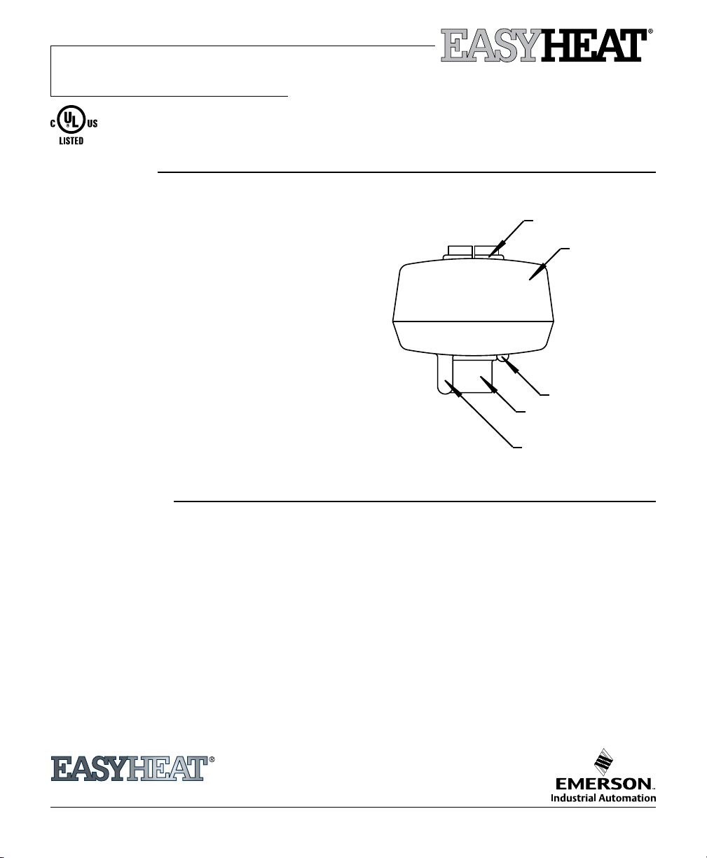
The main components of the SA-1are shown in Fig.1.
The snow and temperature sensors detect snow or ice
conditions and activate, through a power relay, a heating
cable.
Another feature of SA-1 is the LED indicator light. This
light turns red if the snow sensor is dirty and needs to be
cleaned. The red light will switch off automatically when
the snow sensor is cleaned. The LED turns green every
time the power relay is activated and will switch off if the
power relay is off.
Improper installation, use and/or maintenance of the
SA-1 can cause re, electrical shock and/or result in
snow build-up.
WARNINGS
Figure 1
Moisture Sensor
SA-1
Enclosure
LED Indicator
Mounting Connector
.5" (12.70mm) NPT
Temperature Sensor
1. This is not a “do-it-your-self” product. A qualied
electrician must install the SA-1.
2. If after carefully reading these instructions you still
have questions regarding installation, operation or
maintenance of this product, call the numbers listed
for assistance.
3. Prior to installation, check the SA-1 body enclosure or
wires for possible shipping damages. Do not install a
damaged SA-1 controller.
4. All heating cables, controls & associated systems must
be installed in compliance with the latest editions of
all applicable electrical codes and ordinances.
5. These instructions must be saved and made available
to owners or users of this product and/or transferred
to future owners.
6. Any heating cable that is to be connected to the SA-1
US T. (800) 537-4732 / F. (888) 324-2440
CAN T. (800) 794-3766 / F. (800) 361-4574
©2008 Easy Heat www.easyheat.com 14055-001 Rev. 3
must be installed according to the manufacturer’s
instructions.
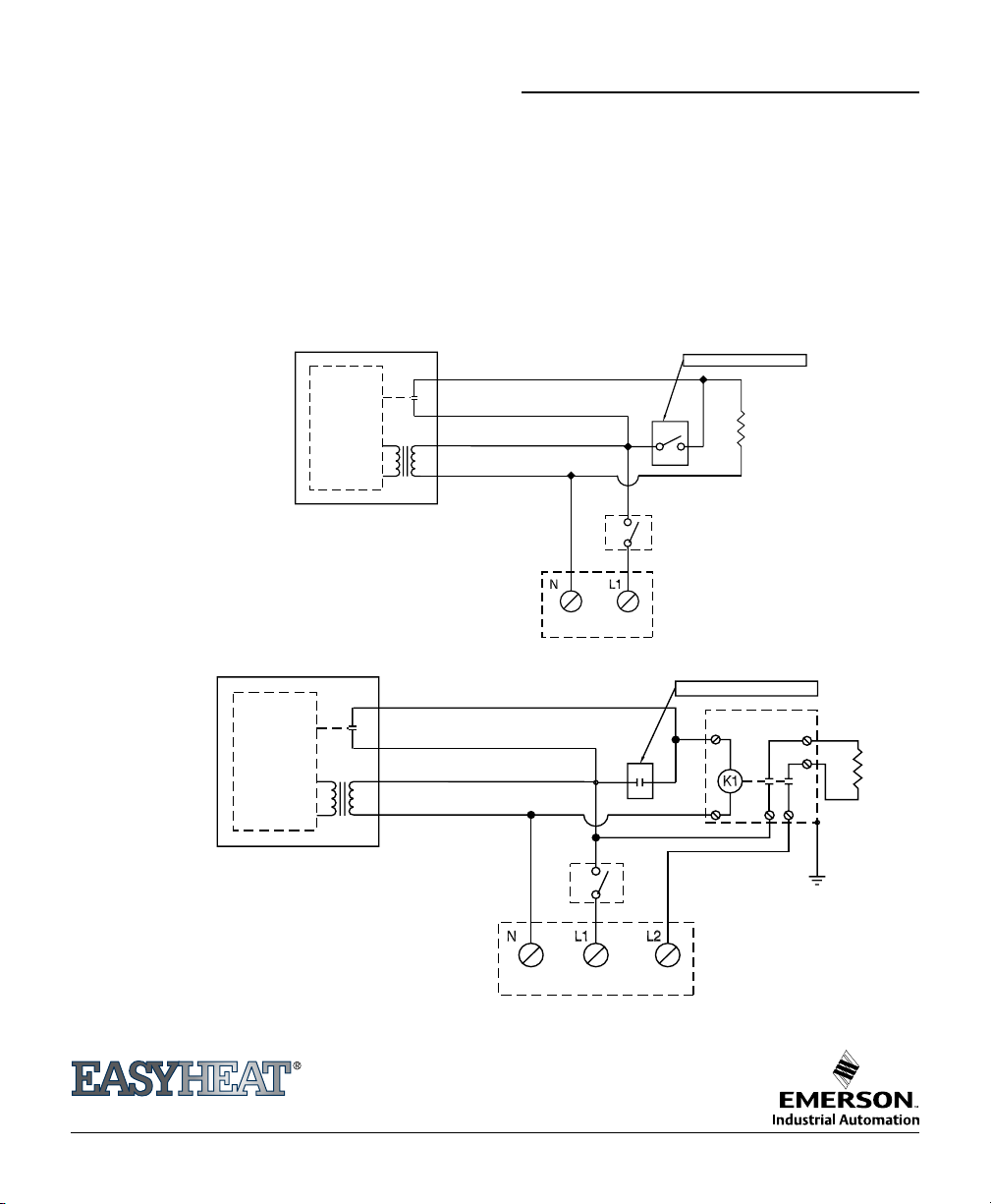
7. Do not connect mo re than 16 Amp load to the
SA-1 (See Fig. 2 & 3). Risk of re, electric shock or
accumulation of snow can result from a larger cable
or from multiple cables being connected.
8. Secure the SA-1 in an area free of obstructions such
as trees, shrubs, etc. to prevent any damages to the
snow sensor.
9. Avoid excessive shock or vibration.
10. Do not touch the surface of the moisture sensor, it is
a hot surface.
Page 2
2 sa-1 Automatic Snow/Ice Melting Controller — Installation & Operation Instructions
SA - 1
AWG #12 RED/YELLOW
AWG #12 RED/YELLOW
AWG #18 BLACK
AWG #18 WHITE
OPTIONAL MANUAL SWITCH OR TIMER
SNOW MELTING
CABLE
OPTIONAL
ON/OFF
SWITCH
SA - 1
AWG #12 RED/YELLOW
AWG #12 RED/YELLOW
AWG #18 BLACK
AWG #18 WHITE
OPTIONAL
ON/OFF
SWITCH
COIL
120
VAC
OPTIONAL MANUAL SWITCH OR TIMER
SNOW MELTING
CABLE
INSTALLATION INSTRUCTIONS
1. Mount the SA-1 securely in upright position in an
open space, in direct contact with snowfall pattern
with a .5" (12.70mm) NPT mounting connector.
The unit is water-resistant, but it is not designed
to be submerged or immersed in water. Ensure
that the mounting location is close, less than
2.5 ft (76.20cm) to the electrical junction box.
See Fig. 4a &4b.
Figure 2 — Installation for Direct Control of Load
*Electrical code may require use of a ground fault protection device.
2. The SA-1 can be connected to the building power
supply as per Fig. 2 or Fig. 3. Before connecting the
controller to the electrical power supply, consult
the local, state or provincial, and national electrical
code. The electrical code may require a Ground
Fault Protection device to be used.
3. Ensure that all pipe connections are sealed to
prevent any penetration of water inside of conduit
or electrical junction box.
Figure 3 —
Installation for Contactor Controlled Load
*Electrical code may require use of a ground fault protection device.
US T. (800) 537-4732 / F. (888) 324-2440
CAN T. (800) 794-3766 / F. (800) 361-4574
www.easyheat.com
Page 3

Automatic Snow/Ice Melting Controller — Installation & Operation Instructions sa-1 3
OPERATION INSTRUCTIONS
The SA-1 snow melting control is designed to energise
the heating cable only when snow or ice conditions exist
and there is risk of freezing. If the temperature is below 3°C
(38°F) and snow is falling, the controller will apply power to
heating cable. The cable remains energised until 2.75 hours
after the snow stops. The delay is necessary to ensure the
heated area dries. If at any time the snow starts falling
again the controller restarts the heating cycle.
In spring or fall when the snow conditions are not very
heavy, the controller may switch on the heated area. For
this situation we recommend having a manual switch
connected in series with the SA-1 to turn it off.
In wintertime the wind may cover the heated area with
snow. The SA-1 can not sense this situations and will not
energise the heating cable. Putting snow on the sensor
surface can energise the SA-1.
The SA-1 may be tested for functionality if the outside
te mp er at ur e is b el ow 25° C (7 7° F) , Submer ge t he
temperature sensor into a glass with ice water for 5 to
10 minutes, wet the surface of the moisture sensor, the
SA-1 should energise the heating cable. After this test,
dry off the sensor, disconnect the power for one minute
and then reconnect it back. The cables should remain
deenergised.
Every year, in the fall the SA-1 must be inspected for
physical damage and to clean up the snow sensor surface.
To clean the snow sensor surface:
1. Disconnect SA-1 from the power supply.
2. With a clean, soft bristle tooth brush clean up the surface
of the snow sensor.
3. Reconnect SA-1 to the power supply.
Roof
Figure 4a
2" (50.80mm) min.
SA-1
.5" (12.70mm) Tubing
Electrical Junction Box
1" (25.40mm)
Gutter
ELECTRICAL SPECIFICATIONS
Functional
Operating temperature +3°C (38°F +/-1°F)
Power switch OFF temperature +45°C (112°F)
Power switch ON temperature +30°C (86°F)
Environmental
Working temperature -40°C (-40°F) to 65°C (150°F)
Storage temperature -45°C (-49°F) to 70°C (160°F)
Humidity environment 0 to 100 %
US T. (800) 537-4732 / F. (888) 324-2440
CAN T. (800) 794-3766 / F. (800) 361-4574
www.easyheat.com
Supply requirements
Power supply voltage 120VAC
Frequency 50/60 Hz
Maximum power consumption 60W
Output characteristics
Output type relay (dry contact)
Contact output N.O. max. 16 Amps @ 120VAC
Mounting connector .5" (12.70mm) NPT
Power wire length 3 feet
Figure 4b
Page 4

4 sa-1 Automatic Snow/Ice Melting Controller — Installation & Operation Instructions
LIMITED WARRANTY
Easy Heat warrants that if there are any defects in material or workmanship in any heating cable or accessory during the first year after the date
of purchase, We will provide new products to replace any defective items, or we will refund the purchase price paid for the accessory or cable, not
including any labor or other installation costs. As an alternate, we may elect to repair the cable or accessory at our factory with all shipping and
other removal costs borne by the purchaser.
We further warrant that for a period of twelve (12) months after the date of performance any services performed hereunder will be in good and
skillful manner, based on our understanding of pertinent technical data as of the date of performance of such services. Easy Heat’s sole responsibility
and liability in the event of any defect, error, omission, or failure in the services rendered hereunder shall be to provide corrected services of the
type provided for herein, designed to correct such defect, error, omissions, or failure, and in no event shall Easy Heat’s liability with respect to such
warranty exceed the amount received by it from the Buyer on account of such services.
Our obligation to provide corrected services, new products, refund the purchase price, or perform the repair described above is conditioned upon
(a) the installation of the accessory or cable conforming to the specifications set forth in our installation instructions and (b) the accessory or cable
not having been damaged by mechanical or electrical activities unrelated to the operation of the accessory or cable.
A refund of your purchase price, provision of replacement products, repair of the accessory or cable or provision of corrected services as
described above, shall be your sole and exclusive remedy for a breach of this warranty. THESE ARE THE SOLE AND EXCLUSIVE WARRANTIES
GIVEN BY EASY HEAT WITH RESPECT TO THE GOODS AND SERVICES AND ARE IN LIEU OF AND EXCLUDE ALL OTHER WARRANTIES,
EXPRESS OR IMPLIED, ARISING BY OPERATION OF LAW OR OTHERWISE, INCLUDING WITHOUT LIMITATION, MERCHANTABILTIY AND
FITNESS FOR A PARTICULAR PURPOSE WHETHER OR NOT THE PURPOSE OR USE HAS BEEN DISCLOSED TO EASY HEAT IN SPECIFICATIONS,
DRAWINGS OR OTHERWISE, AND WHETHER OR NOT EASY HEAT’S PRODUCTS ARE SPECIFICALLY DESIGNED AND /OR MANUFACTURED
BY EASY HEAT FOR YOUR USE OR PURPOSE.
This warranty does not extend to any losses or damages due to misuse, accident, abuse, neglect, normal wear and tear, negligence, unauthorized
modification or alteration, use beyond rate capacity, or improper installation, maintenance or application. To the extent that you or your agents
have supplied specifications, information, representation of operating conditions or other data to Easy Heat in the selection or design of the Goods
and the preparation of Easy Heat’s quotation, and in the event that actual operating conditions or other conditions differ from those represented
by you, any warranties or other provisions contained herein which are affected by such conditions shall be null and void.
If within thirty (30) days after your discovery of any warranty defects within the warranty period, you notify Easy Heat thereof in writing, Easy Heat
shall, at it’s option, repair, correct or replace F.O.B. point of manufacture, or refund the purchase price for that portion of the Goods found by Easy
Heat to be defective. Failure by you to give such written notice within the applicable time period shall be deemed an absolute and unconditional
waiver of your claim for such defects. Goods repaired or replaced during the warranty period shall be covered by the foregoing warranty for the
remainder of the original warranty period or ninety (90) days from the date of shipment of the repaired or replaced goods, whichever is longer.
This limited warranty does not cover any costs relating to the repair or replacement of any accessory or cable at the installation site. Our
accessories and cables are not easily accessible. A failed accessory or cable usually cannot be easily repaired. Replacement of a failed accessory or
cable will require that the materials under which it is installed be removed to permit replacement of the accessory or cable. We will not reimburse
any costs relating to the repair or replacement of any accessory or cable at the installation site.
IN NO EVENT, REGARDLESS OF THE FORM OF THE CLAIM OR CAUSE OF ACTION (WHETHER BASED IN CONTRACT, INFRINGEMENT,
NEGLIGENCE, STRICT LIABILTIY, OTHER TORT OR OTHERWISE), SHALL EASY HEAT’S LIABILTY TO YOU AND/OR YOUR CUSTOMERS
EXCEEED THE PRICE PAID BY YOU FOR THE SPECIFIC GOODS PROVIDED BY EASY HEAT GIVING RISE TO THE CLAIM OR CAUSE OF ACTION.
YOU AGREE THAT WE SHALL NOT BE LIABLE TO YOU OR YOUR CUSTOMERS FOR ANY INCIDENTAL, SPECIAL OR CONSEQUENTIAL OR
PUNITIVE DAMAGES. No agent, employee or representative of ours has authority to bind us to any affirmation, representation or warranty
concerning the goods sold unless such affirmation, representation or warranty is specifically incorporated by written agreement.
To obtain new products, arrange repair of existing product, or a refund under this warranty, please contact Easy Heat with a description of the
defect and proof of purchase at the address noted herein.
ATTN: WARRANTY DEPARTMENT:
US - EasyHeat Inc, 2 Connecticut South Drive, East Granby, CT 06026
CAN - EasyHeat Ltd, 99 Union Street, Elmira, ON N3B 3L7
DISCLAIMER
All information presented in this document was believed correct at the time of printing. We reserve the rights to make
any modications of this document without any prior notication.
US T. (800) 537-4732 / F. (888) 324-2440
CAN T. (800) 794-3766 / F. (800) 361-4574
www.easyheat.com
 Loading...