

Page 1
S5KC™ Series
User Manual – 5-20kVA Modular UPS
Page 2

Page 3

TABLE OF CONTENTS
IMPORTANT SAFETY INSTRUCTIONS . . . . . . . . . . . . . . . . . . . . . . . . . . . . . . . . . . . . . . . . . . . . . . . .1
SAVE THESE INSTRUCTIONS . . . . . . . . . . . . . . . . . . . . . . . . . . . . . . . . . . . . . . . . . . . . . . . . .1
GLOSSARY OF SYMBOLS. . . . . . . . . . . . . . . . . . . . . . . . . . . . . . . . . . . . . . . . . . . . . . . . . . . . . . . .3
1.0 P
RODUCT INTRODUCTION . . . . . . . . . . . . . . . . . . . . . . . . . . . . . . . . . . . . . . . . . . . . . . . . . .4
1.1 System Description. . . . . . . . . . . . . . . . . . . . . . . . . . . . . . . . . . . . . . . . . . . . . . . . . . . . . . . . . . . 4
1.2 Features . . . . . . . . . . . . . . . . . . . . . . . . . . . . . . . . . . . . . . . . . . . . . . . . . . . . . . . . . . . . . . . . . . . 8
1.3 Operating Principle . . . . . . . . . . . . . . . . . . . . . . . . . . . . . . . . . . . . . . . . . . . . . . . . . . . . . . . . . . 9
1.4 Operating Modes . . . . . . . . . . . . . . . . . . . . . . . . . . . . . . . . . . . . . . . . . . . . . . . . . . . . . . . . . . . 10
1.5 Major Components . . . . . . . . . . . . . . . . . . . . . . . . . . . . . . . . . . . . . . . . . . . . . . . . . . . . . . . . . . 11
1.5.1 UPS Frame . . . . . . . . . . . . . . . . . . . . . . . . . . . . . . . . . . . . . . . . . . . . . . . . . . . . . . . . . . . . . . . . . 11
1.5.2 User Interface Module . . . . . . . . . . . . . . . . . . . . . . . . . . . . . . . . . . . . . . . . . . . . . . . . . . . . . . . . 12
1.5.3 System Control Module and System Monitor Module . . . . . . . . . . . . . . . . . . . . . . . . . . . . . . . 12
1.5.4 Power Module . . . . . . . . . . . . . . . . . . . . . . . . . . . . . . . . . . . . . . . . . . . . . . . . . . . . . . . . . . . . . . . 13
1.5.5 Battery Module . . . . . . . . . . . . . . . . . . . . . . . . . . . . . . . . . . . . . . . . . . . . . . . . . . . . . . . . . . . . . . 13
1.5.6 Charger Module . . . . . . . . . . . . . . . . . . . . . . . . . . . . . . . . . . . . . . . . . . . . . . . . . . . . . . . . . . . . . 14
1.5.7 External Battery Cabinet (EBC) . . . . . . . . . . . . . . . . . . . . . . . . . . . . . . . . . . . . . . . . . . . . . . . . 14
2.0 INSTALLATION . . . . . . . . . . . . . . . . . . . . . . . . . . . . . . . . . . . . . . . . . . . . . . . . . . . . . . . . .15
2.1 Unpacking Inspection. . . . . . . . . . . . . . . . . . . . . . . . . . . . . . . . . . . . . . . . . . . . . . . . . . . . . . . . 15
2.1.1 Installation Environment. . . . . . . . . . . . . . . . . . . . . . . . . . . . . . . . . . . . . . . . . . . . . . . . . . . . . . 15
2.1.2 Installation Tools . . . . . . . . . . . . . . . . . . . . . . . . . . . . . . . . . . . . . . . . . . . . . . . . . . . . . . . . . . . . 15
2.1.3 Installation Site . . . . . . . . . . . . . . . . . . . . . . . . . . . . . . . . . . . . . . . . . . . . . . . . . . . . . . . . . . . . . 15
2.2 Unloading the UPS. . . . . . . . . . . . . . . . . . . . . . . . . . . . . . . . . . . . . . . . . . . . . . . . . . . . . . . . . . 16
2.3 Mechanical Installation . . . . . . . . . . . . . . . . . . . . . . . . . . . . . . . . . . . . . . . . . . . . . . . . . . . . . . 17
2.3.1 Tower Installation . . . . . . . . . . . . . . . . . . . . . . . . . . . . . . . . . . . . . . . . . . . . . . . . . . . . . . . . . . . 17
2.3.2 Rack Installation . . . . . . . . . . . . . . . . . . . . . . . . . . . . . . . . . . . . . . . . . . . . . . . . . . . . . . . . . . . . 18
2.4 Module Installation . . . . . . . . . . . . . . . . . . . . . . . . . . . . . . . . . . . . . . . . . . . . . . . . . . . . . . . . . 22
2.4.1 Installing Power Module, Battery Module and Charger Module. . . . . . . . . . . . . . . . . . . . . . . 22
2.4.2 Installing System Control and System Monitor Modules . . . . . . . . . . . . . . . . . . . . . . . . . . . . 24
2.5 Cable Connection . . . . . . . . . . . . . . . . . . . . . . . . . . . . . . . . . . . . . . . . . . . . . . . . . . . . . . . . . . . 25
2.5.1 Transformer-Free UPS Cable Connection . . . . . . . . . . . . . . . . . . . . . . . . . . . . . . . . . . . . . . . . 26
2.5.2 Transformer-Based UPS Cable Connection . . . . . . . . . . . . . . . . . . . . . . . . . . . . . . . . . . . . . . . 28
2.5.3 Transformer-Free UPS—Dual Inverter Frames. . . . . . . . . . . . . . . . . . . . . . . . . . . . . . . . . . . . 32
2.5.4 Connecting External Battery Cabinet. . . . . . . . . . . . . . . . . . . . . . . . . . . . . . . . . . . . . . . . . . . . 34
2.5.5 Connecting Integrated Power Output Distribution (POD) . . . . . . . . . . . . . . . . . . . . . . . . . . . 36
2.5.6 Commissioning/Startup Procedures . . . . . . . . . . . . . . . . . . . . . . . . . . . . . . . . . . . . . . . . . . . . . 37
3.0 COMMUNICATION . . . . . . . . . . . . . . . . . . . . . . . . . . . . . . . . . . . . . . . . . . . . . . . . . . . . . . .39
3.1 IntelliSlot Ports . . . . . . . . . . . . . . . . . . . . . . . . . . . . . . . . . . . . . . . . . . . . . . . . . . . . . . . . . . . . 39
3.2 Dry Contact Ports. . . . . . . . . . . . . . . . . . . . . . . . . . . . . . . . . . . . . . . . . . . . . . . . . . . . . . . . . . . 40
3.3 REPO (Remote Emergency Power Off) . . . . . . . . . . . . . . . . . . . . . . . . . . . . . . . . . . . . . . . . . . 41
i
Page 4

3.4 Long Run Time (LRT) Battery Temperature Probe Terminals . . . . . . . . . . . . . . . . . . . . . . . 42
3.5 USB Port . . . . . . . . . . . . . . . . . . . . . . . . . . . . . . . . . . . . . . . . . . . . . . . . . . . . . . . . . . . . . . . . . . 42
®
3.6 MultiLink
. . . . . . . . . . . . . . . . . . . . . . . . . . . . . . . . . . . . . . . . . . . . . . . . . . . . . . . . . . . . . . . . 43
3.7 LCD Port . . . . . . . . . . . . . . . . . . . . . . . . . . . . . . . . . . . . . . . . . . . . . . . . . . . . . . . . . . . . . . . . . . 43
4.0 OPERATION AND DISPLAY PANEL . . . . . . . . . . . . . . . . . . . . . . . . . . . . . . . . . . . . . . . . . . .44
4.1 Overview . . . . . . . . . . . . . . . . . . . . . . . . . . . . . . . . . . . . . . . . . . . . . . . . . . . . . . . . . . . . . . . . . . 44
4.2 LCD Screen . . . . . . . . . . . . . . . . . . . . . . . . . . . . . . . . . . . . . . . . . . . . . . . . . . . . . . . . . . . . . . . . 46
4.2.1 Startup Screen . . . . . . . . . . . . . . . . . . . . . . . . . . . . . . . . . . . . . . . . . . . . . . . . . . . . . . . . . . . . . . 46
4.2.2 Main Screen . . . . . . . . . . . . . . . . . . . . . . . . . . . . . . . . . . . . . . . . . . . . . . . . . . . . . . . . . . . . . . . . 46
4.2.3 Default Screen/Screen Saver . . . . . . . . . . . . . . . . . . . . . . . . . . . . . . . . . . . . . . . . . . . . . . . . . . . 51
4.3 LCD Screen Views . . . . . . . . . . . . . . . . . . . . . . . . . . . . . . . . . . . . . . . . . . . . . . . . . . . . . . . . . . 51
4.3.1 AC Mains Screen . . . . . . . . . . . . . . . . . . . . . . . . . . . . . . . . . . . . . . . . . . . . . . . . . . . . . . . . . . . . 51
4.3.2 Battery Screen . . . . . . . . . . . . . . . . . . . . . . . . . . . . . . . . . . . . . . . . . . . . . . . . . . . . . . . . . . . . . . 52
4.3.3 Output Screen. . . . . . . . . . . . . . . . . . . . . . . . . . . . . . . . . . . . . . . . . . . . . . . . . . . . . . . . . . . . . . . 52
4.3.4 Load Screen. . . . . . . . . . . . . . . . . . . . . . . . . . . . . . . . . . . . . . . . . . . . . . . . . . . . . . . . . . . . . . . . . 53
4.3.5 UPS Information Screen . . . . . . . . . . . . . . . . . . . . . . . . . . . . . . . . . . . . . . . . . . . . . . . . . . . . . . 53
4.3.6 Redundancy Screen . . . . . . . . . . . . . . . . . . . . . . . . . . . . . . . . . . . . . . . . . . . . . . . . . . . . . . . . . . 54
4.3.7 Settings Screen . . . . . . . . . . . . . . . . . . . . . . . . . . . . . . . . . . . . . . . . . . . . . . . . . . . . . . . . . . . . . . 55
4.4 Entering a Password . . . . . . . . . . . . . . . . . . . . . . . . . . . . . . . . . . . . . . . . . . . . . . . . . . . . . . . . 55
4.5 Setting or Changing a Parameter Setting . . . . . . . . . . . . . . . . . . . . . . . . . . . . . . . . . . . . . . . 56
4.5.1 Battery Setting Screen . . . . . . . . . . . . . . . . . . . . . . . . . . . . . . . . . . . . . . . . . . . . . . . . . . . . . . . . 56
4.5.2 Language Selection Screen . . . . . . . . . . . . . . . . . . . . . . . . . . . . . . . . . . . . . . . . . . . . . . . . . . . . 56
4.5.3 Alarms Screen. . . . . . . . . . . . . . . . . . . . . . . . . . . . . . . . . . . . . . . . . . . . . . . . . . . . . . . . . . . . . . . 57
4.5.4 Records Screen . . . . . . . . . . . . . . . . . . . . . . . . . . . . . . . . . . . . . . . . . . . . . . . . . . . . . . . . . . . . . . 57
4.5.5 Module Replacement Screen . . . . . . . . . . . . . . . . . . . . . . . . . . . . . . . . . . . . . . . . . . . . . . . . . . . 58
4.5.6 Prompt Window . . . . . . . . . . . . . . . . . . . . . . . . . . . . . . . . . . . . . . . . . . . . . . . . . . . . . . . . . . . . . 58
5.0 TROUBLESHOOTING . . . . . . . . . . . . . . . . . . . . . . . . . . . . . . . . . . . . . . . . . . . . . . . . . . . . .60
5.1 Active Alarms . . . . . . . . . . . . . . . . . . . . . . . . . . . . . . . . . . . . . . . . . . . . . . . . . . . . . . . . . . . . . . 60
5.2 Module Troubleshooting. . . . . . . . . . . . . . . . . . . . . . . . . . . . . . . . . . . . . . . . . . . . . . . . . . . . . . 63
5.3 Module Replacement . . . . . . . . . . . . . . . . . . . . . . . . . . . . . . . . . . . . . . . . . . . . . . . . . . . . . . . . 64
5.3.1 Removing Modules . . . . . . . . . . . . . . . . . . . . . . . . . . . . . . . . . . . . . . . . . . . . . . . . . . . . . . . . . . . 64
5.3.2 Replacing the User Interface Module . . . . . . . . . . . . . . . . . . . . . . . . . . . . . . . . . . . . . . . . . . . . 65
6.0 MAINTENANCE . . . . . . . . . . . . . . . . . . . . . . . . . . . . . . . . . . . . . . . . . . . . . . . . . . . . . . . . .67
6.1 Proper Care. . . . . . . . . . . . . . . . . . . . . . . . . . . . . . . . . . . . . . . . . . . . . . . . . . . . . . . . . . . . . . . . 67
6.2 Scheduled Maintenance . . . . . . . . . . . . . . . . . . . . . . . . . . . . . . . . . . . . . . . . . . . . . . . . . . . . . . 67
6.3 Cleaning Fan Filters . . . . . . . . . . . . . . . . . . . . . . . . . . . . . . . . . . . . . . . . . . . . . . . . . . . . . . . . 67
6.3.1 Top Filter . . . . . . . . . . . . . . . . . . . . . . . . . . . . . . . . . . . . . . . . . . . . . . . . . . . . . . . . . . . . . . . . . . 67
6.3.2 Bezel Filter . . . . . . . . . . . . . . . . . . . . . . . . . . . . . . . . . . . . . . . . . . . . . . . . . . . . . . . . . . . . . . . . . 68
6.3.3 Bottom Fan Filter—Transformer-Based Frames Only . . . . . . . . . . . . . . . . . . . . . . . . . . . . . . 68
7.0 SPECIFICATIONS. . . . . . . . . . . . . . . . . . . . . . . . . . . . . . . . . . . . . . . . . . . . . . . . . . . . . . . .69
7.1 Estimated Battery Run Times. . . . . . . . . . . . . . . . . . . . . . . . . . . . . . . . . . . . . . . . . . . . . . . . . 72
7.1.1 Tables for UPS Where Model Number Digits 1-4 are S5KA . . . . . . . . . . . . . . . . . . . . . . . . . . 72
ii
Page 5

7.2 Estimated Battery Run Times. . . . . . . . . . . . . . . . . . . . . . . . . . . . . . . . . . . . . . . . . . . . . . . . . 75
7.2.1 Tables for UPS Model Number Where Digits 1-4 are S5KB . . . . . . . . . . . . . . . . . . . . . . . . . . 75
7.3 Estimated Battery Run Times. . . . . . . . . . . . . . . . . . . . . . . . . . . . . . . . . . . . . . . . . . . . . . . . . 78
7.3.1 Tables for UPS model number digits 1-4 are S5KC . . . . . . . . . . . . . . . . . . . . . . . . . . . . . . . . . 78
7.4 Estimated Battery Run Times. . . . . . . . . . . . . . . . . . . . . . . . . . . . . . . . . . . . . . . . . . . . . . . . . 81
7.4.1 Tables for UPS Model Number Where Digits 1-4 are S5KD . . . . . . . . . . . . . . . . . . . . . . . . . . 81
7.5 Estimated Battery Run Times. . . . . . . . . . . . . . . . . . . . . . . . . . . . . . . . . . . . . . . . . . . . . . . . . 84
7.5.1 Tables for UPS Model Number Where Digits 1-4 are S5KE . . . . . . . . . . . . . . . . . . . . . . . . . . 84
7.6 Estimated Battery Run Times. . . . . . . . . . . . . . . . . . . . . . . . . . . . . . . . . . . . . . . . . . . . . . . . . 87
7.6.1 Tables for UPS Model Number Where Digits 1-4 are S5KF . . . . . . . . . . . . . . . . . . . . . . . . . . 87
FIGURES
Figure 1 16-bay transformer-free UPS . . . . . . . . . . . . . . . . . . . . . . . . . . . . . . . . . . . . . . . . . . . . . . . . . . . . . . . 5
Figure 2 10-bay transformer-free UPS . . . . . . . . . . . . . . . . . . . . . . . . . . . . . . . . . . . . . . . . . . . . . . . . . . . . . . . 5
Figure 3 12-bay transformer-based UPS . . . . . . . . . . . . . . . . . . . . . . . . . . . . . . . . . . . . . . . . . . . . . . . . . . . . . 6
Figure 4 16-bay transformer-based UPS . . . . . . . . . . . . . . . . . . . . . . . . . . . . . . . . . . . . . . . . . . . . . . . . . . . . . 7
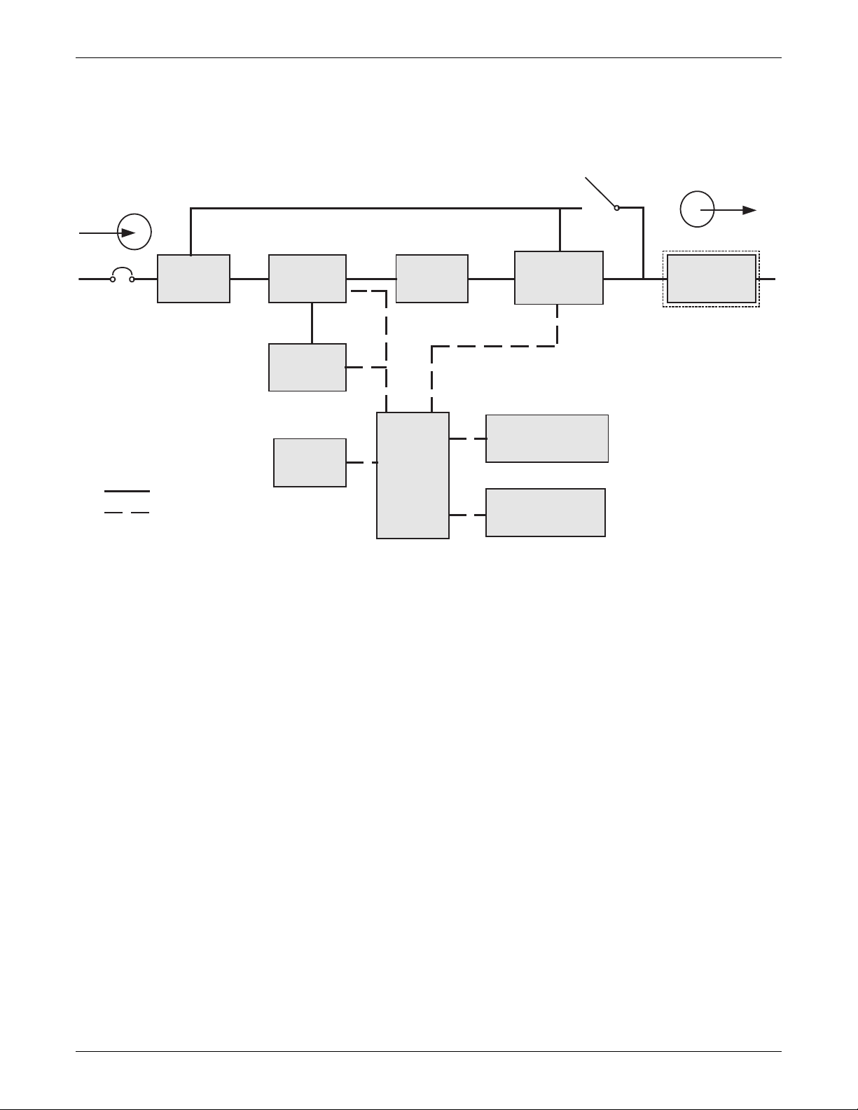
Figure 5 Operating principle diagram . . . . . . . . . . . . . . . . . . . . . . . . . . . . . . . . . . . . . . . . . . . . . . . . . . . . . . . 9
Figure 6 UPS frames, bezels removed . . . . . . . . . . . . . . . . . . . . . . . . . . . . . . . . . . . . . . . . . . . . . . . . . . . . . . 11
Figure 7 User interface module. . . . . . . . . . . . . . . . . . . . . . . . . . . . . . . . . . . . . . . . . . . . . . . . . . . . . . . . . . . . 12
Figure 8 SolaHD S5KC system control module and the system monitor module . . . . . . . . . . . . . . . . . . . . 12
Figure 9 SolaHD S5KC power module . . . . . . . . . . . . . . . . . . . . . . . . . . . . . . . . . . . . . . . . . . . . . . . . . . . . . . 13
Figure 10 Battery module appearance . . . . . . . . . . . . . . . . . . . . . . . . . . . . . . . . . . . . . . . . . . . . . . . . . . . . . . . 13
Figure 11 Appearance of the charger module. . . . . . . . . . . . . . . . . . . . . . . . . . . . . . . . . . . . . . . . . . . . . . . . . . 14
Figure 12 External battery cabinet. . . . . . . . . . . . . . . . . . . . . . . . . . . . . . . . . . . . . . . . . . . . . . . . . . . . . . . . . . 14
Figure 13 Front and rear installation clearances . . . . . . . . . . . . . . . . . . . . . . . . . . . . . . . . . . . . . . . . . . . . . . 15
Figure 14 Remove the mounting brackets . . . . . . . . . . . . . . . . . . . . . . . . . . . . . . . . . . . . . . . . . . . . . . . . . . . . 16
Figure 15 Connect the ramp and remove UPS. . . . . . . . . . . . . . . . . . . . . . . . . . . . . . . . . . . . . . . . . . . . . . . . . 16
Figure 16 Adjust the leveling feet . . . . . . . . . . . . . . . . . . . . . . . . . . . . . . . . . . . . . . . . . . . . . . . . . . . . . . . . . . . 17
Figure 17 Installation position and drilling hole dimensions for stationary mounting. . . . . . . . . . . . . . . . . 17
Figure 18 Install cage nuts . . . . . . . . . . . . . . . . . . . . . . . . . . . . . . . . . . . . . . . . . . . . . . . . . . . . . . . . . . . . . . . . 18
Figure 19 Install the tray . . . . . . . . . . . . . . . . . . . . . . . . . . . . . . . . . . . . . . . . . . . . . . . . . . . . . . . . . . . . . . . . . 18
Figure 20 Install the guide rails . . . . . . . . . . . . . . . . . . . . . . . . . . . . . . . . . . . . . . . . . . . . . . . . . . . . . . . . . . . . 19
Figure 21 Install the brackets . . . . . . . . . . . . . . . . . . . . . . . . . . . . . . . . . . . . . . . . . . . . . . . . . . . . . . . . . . . . . . 19
Figure 22 Push the UPS frame into the rack . . . . . . . . . . . . . . . . . . . . . . . . . . . . . . . . . . . . . . . . . . . . . . . . . . 20
Figure 23 Fix the UPS frame . . . . . . . . . . . . . . . . . . . . . . . . . . . . . . . . . . . . . . . . . . . . . . . . . . . . . . . . . . . . . . 20
Figure 24 Install the metal plate . . . . . . . . . . . . . . . . . . . . . . . . . . . . . . . . . . . . . . . . . . . . . . . . . . . . . . . . . . . 21
Figure 25 Installation completed . . . . . . . . . . . . . . . . . . . . . . . . . . . . . . . . . . . . . . . . . . . . . . . . . . . . . . . . . . . 21
Figure 26 Insert the power module, battery module and charger module . . . . . . . . . . . . . . . . . . . . . . . . . . . 22
Figure 27 Lever and fastener . . . . . . . . . . . . . . . . . . . . . . . . . . . . . . . . . . . . . . . . . . . . . . . . . . . . . . . . . . . . . . 23
Figure 28 Remove large display bezel and user interface module . . . . . . . . . . . . . . . . . . . . . . . . . . . . . . . . . 24
Figure 29 Insert the System Control and System Monitor module . . . . . . . . . . . . . . . . . . . . . . . . . . . . . . . . 24
Figure 30 Lever and fastener on System Control and System Monitor Module . . . . . . . . . . . . . . . . . . . . . . 25
Figure 31 Knockouts . . . . . . . . . . . . . . . . . . . . . . . . . . . . . . . . . . . . . . . . . . . . . . . . . . . . . . . . . . . . . . . . . . . . . 26
Figure 32 Connection in single-phase input. . . . . . . . . . . . . . . . . . . . . . . . . . . . . . . . . . . . . . . . . . . . . . . . . . . 27
Figure 33 Connection in 3-phase input. . . . . . . . . . . . . . . . . . . . . . . . . . . . . . . . . . . . . . . . . . . . . . . . . . . . . . . 27
Figure 34 Setting bypass voltage jumper (default: 208VAC) . . . . . . . . . . . . . . . . . . . . . . . . . . . . . . . . . . . . . 29
Figure 35 Setting bypass voltage jumper (200/220/230/240VAC) . . . . . . . . . . . . . . . . . . . . . . . . . . . . . . . . . . 29
Figure 36 Configuring the neutral/earth jumper . . . . . . . . . . . . . . . . . . . . . . . . . . . . . . . . . . . . . . . . . . . . . . . 30
iii
Page 6

Figure 37 Knockouts . . . . . . . . . . . . . . . . . . . . . . . . . . . . . . . . . . . . . . . . . . . . . . . . . . . . . . . . . . . . . . . . . . . . . 30
Figure 38 Connection method . . . . . . . . . . . . . . . . . . . . . . . . . . . . . . . . . . . . . . . . . . . . . . . . . . . . . . . . . . . . . . 31
Figure 39 Knockouts . . . . . . . . . . . . . . . . . . . . . . . . . . . . . . . . . . . . . . . . . . . . . . . . . . . . . . . . . . . . . . . . . . . . . 32
Figure 40 Secure cables on cable bridges . . . . . . . . . . . . . . . . . . . . . . . . . . . . . . . . . . . . . . . . . . . . . . . . . . . . . 33
Figure 41 Wiring connections . . . . . . . . . . . . . . . . . . . . . . . . . . . . . . . . . . . . . . . . . . . . . . . . . . . . . . . . . . . . . . 33
Figure 42 Connecting external battery cabinet to a transformer-free UPS . . . . . . . . . . . . . . . . . . . . . . . . . . 35
Figure 43 Connecting external battery cabinet (transformer-based UPS). . . . . . . . . . . . . . . . . . . . . . . . . . . 35
Figure 44 Battery screen . . . . . . . . . . . . . . . . . . . . . . . . . . . . . . . . . . . . . . . . . . . . . . . . . . . . . . . . . . . . . . . . . . 36
Figure 45 IntelliSlot communication port location . . . . . . . . . . . . . . . . . . . . . . . . . . . . . . . . . . . . . . . . . . . . . 39
Figure 46 Pin layout of the dry contacts. . . . . . . . . . . . . . . . . . . . . . . . . . . . . . . . . . . . . . . . . . . . . . . . . . . . . . 40
Figure 47 REPO connector pin layout . . . . . . . . . . . . . . . . . . . . . . . . . . . . . . . . . . . . . . . . . . . . . . . . . . . . . . . 41
Figure 48 REPO switch connections . . . . . . . . . . . . . . . . . . . . . . . . . . . . . . . . . . . . . . . . . . . . . . . . . . . . . . . . 41
Figure 49 Pin layout of the temperature sensor terminal . . . . . . . . . . . . . . . . . . . . . . . . . . . . . . . . . . . . . . . . 42
Figure 50 LCD port . . . . . . . . . . . . . . . . . . . . . . . . . . . . . . . . . . . . . . . . . . . . . . . . . . . . . . . . . . . . . . . . . . . . . . 43
Figure 51 Operation and display panel . . . . . . . . . . . . . . . . . . . . . . . . . . . . . . . . . . . . . . . . . . . . . . . . . . . . . . 44
Figure 52 User interface module layout . . . . . . . . . . . . . . . . . . . . . . . . . . . . . . . . . . . . . . . . . . . . . . . . . . . . . . 45
Figure 53 Startup screen . . . . . . . . . . . . . . . . . . . . . . . . . . . . . . . . . . . . . . . . . . . . . . . . . . . . . . . . . . . . . . . . . . 46
Figure 54 Main screen . . . . . . . . . . . . . . . . . . . . . . . . . . . . . . . . . . . . . . . . . . . . . . . . . . . . . . . . . . . . . . . . . . . . 46
Figure 55 Default screen/screen saver . . . . . . . . . . . . . . . . . . . . . . . . . . . . . . . . . . . . . . . . . . . . . . . . . . . . . . . 51
Figure 56 Mains screen . . . . . . . . . . . . . . . . . . . . . . . . . . . . . . . . . . . . . . . . . . . . . . . . . . . . . . . . . . . . . . . . . . . 51
Figure 57 Battery screens . . . . . . . . . . . . . . . . . . . . . . . . . . . . . . . . . . . . . . . . . . . . . . . . . . . . . . . . . . . . . . . . . 52
Figure 58 Output screen . . . . . . . . . . . . . . . . . . . . . . . . . . . . . . . . . . . . . . . . . . . . . . . . . . . . . . . . . . . . . . . . . . 52
Figure 59 Load screen . . . . . . . . . . . . . . . . . . . . . . . . . . . . . . . . . . . . . . . . . . . . . . . . . . . . . . . . . . . . . . . . . . . . 53
Figure 60 UPS info screen . . . . . . . . . . . . . . . . . . . . . . . . . . . . . . . . . . . . . . . . . . . . . . . . . . . . . . . . . . . . . . . . . 53
Figure 61 Redundancy screen . . . . . . . . . . . . . . . . . . . . . . . . . . . . . . . . . . . . . . . . . . . . . . . . . . . . . . . . . . . . . . 54
Figure 62 Settings screens. . . . . . . . . . . . . . . . . . . . . . . . . . . . . . . . . . . . . . . . . . . . . . . . . . . . . . . . . . . . . . . . . 55
Figure 63 Battery settings screen . . . . . . . . . . . . . . . . . . . . . . . . . . . . . . . . . . . . . . . . . . . . . . . . . . . . . . . . . . . 56
Figure 64 Language selection screen . . . . . . . . . . . . . . . . . . . . . . . . . . . . . . . . . . . . . . . . . . . . . . . . . . . . . . . . 56
Figure 65 Alarms screen . . . . . . . . . . . . . . . . . . . . . . . . . . . . . . . . . . . . . . . . . . . . . . . . . . . . . . . . . . . . . . . . . . 57
Figure 66 Records screen . . . . . . . . . . . . . . . . . . . . . . . . . . . . . . . . . . . . . . . . . . . . . . . . . . . . . . . . . . . . . . . . . . 57
Figure 67 Module replacement screen . . . . . . . . . . . . . . . . . . . . . . . . . . . . . . . . . . . . . . . . . . . . . . . . . . . . . . . 58
Figure 68 Example of prompt window . . . . . . . . . . . . . . . . . . . . . . . . . . . . . . . . . . . . . . . . . . . . . . . . . . . . . . . 58
Figure 69 Module LED location . . . . . . . . . . . . . . . . . . . . . . . . . . . . . . . . . . . . . . . . . . . . . . . . . . . . . . . . . . . . 63
Figure 70 Lever and fastener . . . . . . . . . . . . . . . . . . . . . . . . . . . . . . . . . . . . . . . . . . . . . . . . . . . . . . . . . . . . . . 64
Figure 71 Pull out a battery module, a power module or a charge module . . . . . . . . . . . . . . . . . . . . . . . . . . 65
Figure 72 Replacing the user interface module . . . . . . . . . . . . . . . . . . . . . . . . . . . . . . . . . . . . . . . . . . . . . . . . 66
Figure 73 Replace/clean the top filter . . . . . . . . . . . . . . . . . . . . . . . . . . . . . . . . . . . . . . . . . . . . . . . . . . . . . . . . 67
Figure 74 Replace/clean the bezel filter . . . . . . . . . . . . . . . . . . . . . . . . . . . . . . . . . . . . . . . . . . . . . . . . . . . . . . 68
Figure 75 Replace/clean the bottom fan filter . . . . . . . . . . . . . . . . . . . . . . . . . . . . . . . . . . . . . . . . . . . . . . . . . 68
iv
Page 7

TABLES
Table 1 Frame designation . . . . . . . . . . . . . . . . . . . . . . . . . . . . . . . . . . . . . . . . . . . . . . . . . . . . . . . . . . . . . . . 4
Table 2 Cable connection method reference . . . . . . . . . . . . . . . . . . . . . . . . . . . . . . . . . . . . . . . . . . . . . . . . . 25
Table 3 Input cable selection list—60Hz. . . . . . . . . . . . . . . . . . . . . . . . . . . . . . . . . . . . . . . . . . . . . . . . . . . . 26
Table 4 Input cable selection list—50Hz. . . . . . . . . . . . . . . . . . . . . . . . . . . . . . . . . . . . . . . . . . . . . . . . . . . . 26
Table 5 Input cable selection for transformer-based frames (60 Hz) . . . . . . . . . . . . . . . . . . . . . . . . . . . . . 28
Table 6 Key to Figures 32 and 33 UPS wiring . . . . . . . . . . . . . . . . . . . . . . . . . . . . . . . . . . . . . . . . . . . . . . 28
Table 7 Input cable selection for transformer-based frames (50 Hz) . . . . . . . . . . . . . . . . . . . . . . . . . . . . . 29
Table 8 Key to Figure 38 UPS input wiring . . . . . . . . . . . . . . . . . . . . . . . . . . . . . . . . . . . . . . . . . . . . . . . . 31
Table 9 Key to Figure 38 UPS output wiring . . . . . . . . . . . . . . . . . . . . . . . . . . . . . . . . . . . . . . . . . . . . . . . 31
Table 10 Maximum load capacity of the output winding . . . . . . . . . . . . . . . . . . . . . . . . . . . . . . . . . . . . . . . . 31
Table 11 Input cable selection for transformer-free dual inverter frames (50/60 Hz) . . . . . . . . . . . . . . . . . 32
Table 12 Input cable selection for transformer-free dual inverter frames (50/60 Hz) . . . . . . . . . . . . . . . . . 32
Table 13 EBC DIP switch settings . . . . . . . . . . . . . . . . . . . . . . . . . . . . . . . . . . . . . . . . . . . . . . . . . . . . . . . . . 36
Table 14 Pin definition of dry contact port . . . . . . . . . . . . . . . . . . . . . . . . . . . . . . . . . . . . . . . . . . . . . . . . . . . 40
Table 15 Pin definition of the REPO dry contact . . . . . . . . . . . . . . . . . . . . . . . . . . . . . . . . . . . . . . . . . . . . . . 41
Table 16 Pin definition of the temperature sensor terminal . . . . . . . . . . . . . . . . . . . . . . . . . . . . . . . . . . . . . 42
Table 17 LED descriptions. . . . . . . . . . . . . . . . . . . . . . . . . . . . . . . . . . . . . . . . . . . . . . . . . . . . . . . . . . . . . . . . 44
Table 18 Audible alarm descriptions. . . . . . . . . . . . . . . . . . . . . . . . . . . . . . . . . . . . . . . . . . . . . . . . . . . . . . . . 45
Table 19 Control buttons functions . . . . . . . . . . . . . . . . . . . . . . . . . . . . . . . . . . . . . . . . . . . . . . . . . . . . . . . . . 45
Table 20 Function descriptions of menu button . . . . . . . . . . . . . . . . . . . . . . . . . . . . . . . . . . . . . . . . . . . . . . . 45
Table 21 Item description of system information window . . . . . . . . . . . . . . . . . . . . . . . . . . . . . . . . . . . . . . . 46
Table 22 Item description of menu window and data window. . . . . . . . . . . . . . . . . . . . . . . . . . . . . . . . . . . . 47
Table 23 Function descriptions of menu buttons . . . . . . . . . . . . . . . . . . . . . . . . . . . . . . . . . . . . . . . . . . . . . . 50
Table 24 Information and actions required for the prompt window . . . . . . . . . . . . . . . . . . . . . . . . . . . . . . . 59
Table 25 Alarm message list . . . . . . . . . . . . . . . . . . . . . . . . . . . . . . . . . . . . . . . . . . . . . . . . . . . . . . . . . . . . . . 60
Table 26 Descriptions of module LEDs . . . . . . . . . . . . . . . . . . . . . . . . . . . . . . . . . . . . . . . . . . . . . . . . . . . . . . 63
Table 27 SolaHD S5KC specifications. . . . . . . . . . . . . . . . . . . . . . . . . . . . . . . . . . . . . . . . . . . . . . . . . . . . . . . 69
Table 28 Rated input voltage range (Unit: VAC) . . . . . . . . . . . . . . . . . . . . . . . . . . . . . . . . . . . . . . . . . . . . . . 71
Table 29 SolaHD S5KC external battery cabinet specifications . . . . . . . . . . . . . . . . . . . . . . . . . . . . . . . . . . 71
Table 30 10-bay, single-phase, no transformer unit Type N (& UPS model number digit 9 = N). . . . . . . . 72
Table 31 10-bay, single-phase, no transformer unit Type R (& UPS model number digit 9 = R) . . . . . . . . 73
Table 32 10-bay, single-phase, no transformer unit Type F (& UPS model number digit 9 = F) . . . . . . . . 74
Table 33 16-bay, single-phase, no transformer unit Type N (& UPS model number digit 9 = N). . . . . . . . 75
Table 34 16-bay, single-phase, no transformer unit Type R (& UPS model number digit 9 = R) . . . . . . . . 76
Table 35 16-bay, single-phase, no transformer unit Type F (& UPS model number digit 9 = F) . . . . . . . . 77
Table 36 12-bay, single-phase, transformer-based unit Type N (& UPS model number 9 = N) . . . . . . . . . 78
Table 37 12-bay, single-phase, transformer-based unit Type R (& UPS model number 9 = R). . . . . . . . . . 79
Table 38 12-bay, single-phase, transformer-based unit Type F (& UPS model number 9 = F) . . . . . . . . . . 80
Table 39 16-bay, single-phase, transformer-based unit Type N (& UPS model number 9 = N) . . . . . . . . . 81
Table 40 16-bay, single-phase, transformer-based unit Type R
Table 41 16-bay, single-phase, transformer-based unit Type F (& UPS model number 9 = F) . . . . . . . . . . 83
Table 42 10-bay, two-phase, no transformer unit Type N (& UPS model number 9 = N) . . . . . . . . . . . . . . 84
Table 43 10-bay, two-phase, no transformer unit Type R (& UPS model number 9 = R) . . . . . . . . . . . . . . 85
Table 44 10-bay, two-phase, no transformer unit Type F (& UPS model number 9 = F). . . . . . . . . . . . . . . 86
Table 45 16-bay, two-phase, no transformer, unit Type N (& UPS model number 9 = N) . . . . . . . . . . . . . 87
Table 46 16-bay, two-phase, no transformer unit Type R (& UPS model number 9 = R) . . . . . . . . . . . . . . 88
Table 47 16-bay, two-phase, no transformer unit Type F (& UPS model number 9 = F). . . . . . . . . . . . . . . 89
(& UPS model number 96 = R). . . . . . . . . 82
v
Page 8

vi
Page 9
IMPORTANT SAFETY INSTRUCTIONS
!
!
!
SAVE THESE INSTRUCTIONS
This manual contains important safety instructions. Read all safety, installation and operating
instructions before operating the SolaHD S5KC modular UPS system. Adhere to all warnings on the
unit and in this manual. Follow all operating and user instructions. Individuals must fully
understand this equipment to install and operate it.
This product is designed for commercial/industrial use only. It is not intended for use with life support
or other designated critical devices. Maximum load must not exceed that shown on the rating label.
Install and operate the unit only in an indoor clean environment, free from conductive contaminants,
moisture, flammable liquids, gases and corrosive substances. This SolaHD S5KC contains no user
serviceable parts other than the user replaceable modules. Refer all faults to your local dealer, local
Emerson representative or the Emerson SolaHD service group.
The SolaHD S5KC UPS system is designed for use on a properly earthed (grounded) “TN” electrical
supply, for installation by qualified personnel. A qualified electrician must review and approve
customer supplied wiring, circuit breakers, and intended loads and verify correct input, output, and
earth connections to ensure compliance with the technical standards and local electrical codes of
practice. Installation instructions and warning notices are found in this manual.
WARNING
Risk of electric shock. Can cause equipment damage, injury and death.
The battery can present a risk of electrical shock and high short circuit current. The following
precautions should be observed before replacing the battery pack:
• Wear rubber gloves and boots
• Remove rings, watches and other metal objects.
• Use tools with insulated handles.
• Do not lay tools or other metal objects on the batteries.
• If the battery kit is damaged in any way or shows signs of leakage, contact your local
Emerson representative immediately.
• Do not dispose of batteries in a fire. The batteries may explode.
• Handle, transport and recycle batteries in accordance with local regulations.
Important Safety Instructions
WARNING
Risk of electric shock and fire. Can cause equipment damage, injury and death.
Although the SolaHD S5KC UPS has been designed and manufactured to ensure personal
safety, improper use can result in electrical shock or fire. To ensure safety, observe the
following precautions:
• Clean the UPS with a dry cloth. Do not use liquid or aerosol cleaners.
• Never block or insert any objects into the ventilation holes or other openings of the UPS.
• Do not place the SolaHD S5KC where it might be damaged.
WARNING
Risk of electric shock. Can cause equipment damage, injury and death.
This UPS contains no user-serviceable parts except for the user-replaceable module
assemblies. The UPS On/Off push button does not electrically isolate internal parts.
All service and maintenance operations must be performed by properly trained and qualified
personnel. Under no circumstances should unqualified or unauthorized personnel attempt to
gain access to the internal portions of the SolaHD S5KC.
1 SOLA HD® S5KC
™
Page 10

Important Safety Instructions
ELECTROMAGNETIC COMPATIBILITY—The SolaHD S5KC complies with the limits of
Category C2, pursuant to IEC/EN/AS 62040-2, and for a Class A digital device, pursuant to Part 15 of
FCC rules. Operation is subject to the following conditions:
• The output cables shall be no longer than 10m (32ft).
• This device may not cause harmful interference.
• This device must accept any interference received, including interference that may cause
undesired operation. Operating this device in a residential area is likely to cause harmful
interference that users must correct at their own expense.
The SolaHD S5KC complies with the requirements of EMC Directive 2004/108/EC and the published
technical standards. Continued compliance requires installation in accordance with these
instructions and use of accessories approved by Emerson.
Operate the UPS in an indoor environment only in an ambient temperature range of 0-40°C
(32-104°F). Install it in a clean environment, free from moisture, flammable liquids, gases and
corrosive substances.
Do not continue to use the UPS if the front panel indications are not in accordance with these
operating instructions or the UPS performance alters in use. Refer all faults to your local service
dealer.
Servicing of batteries should be performed or supervised by personnel knowledgeable of batteries and
the required precautions. Keep unauthorized personnel away from the batteries. Proper disposal of
batteries is required. Refer to your local laws and regulations for disposal requirements.
Never block or insert any object into the ventilation holes or other openings.
DO NOT CONNECT equipment that could overload the UPS or demand DC current from the UPS,
for example: electric drills, vacuum cleaners, laser printers, hair dryers or any appliance using half
wave rectification.
Storing magnetic media on top of the UPS may result in data loss or corruption. Turn Off and isolate
the UPS before cleaning it. Use only a soft dry cloth; never use liquid or aerosol cleaners.
Information for the Protection of the Environment
UPS SERVICING—This UPS makes use of components dangerous for the environment (electronic
cards, electronic components). The components removed must be taken to specialized collection and
disposal centers.
NOTICE TO EUROPEAN UNION CUSTOMERS: DISPOSAL OF OLD
APPLIANCES—This product has been supplied from an environmentally aware
manufacturer that complies with the Waste Electrical and Electronic Equipment
(WEEE) Directive 2002/96/CE.
The crossed-out trash bin symbol at right is placed on this product to encourage
users to recycle components and units whenever possible. Please be
environmentally responsible and recycle this product through your recycling
facility at its end of life. Do not dispose of this product as unsorted municipal
waste. Follow local municipal waste ordinances for proper disposal provisions to
reduce the environmental impact of waste electrical and electronic equipment (WEEE).
For information regarding the scrapping/disposal of this equipment, please browse
www.solahd.com (Products section or Contact us section) or call Emerson’s worldwide technical
support.
• Toll-Free in North America: 1-800-377-4384
• Outside North America: +1-847-268-6651
•Email: solahd.technicalservices@emerson.com
SOLA HD® S5KC
™
2
Page 11
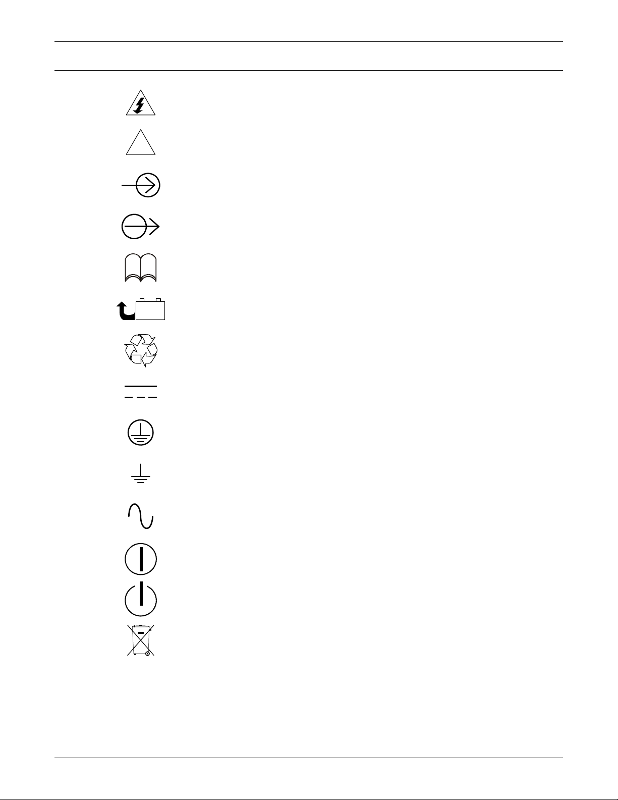
GLOSSARY OF SYMBOLS
!
PbH2SO4
-
+
R
Glossary of Symbols
Risk of electrical shock
Indicates caution followed by important instructions
AC input
AC output
i
Requests the user to consult the manual
Indicates the unit contains a valve-regulated lead acid battery
Recycle
DC voltage
Equipment grounding conductor
Bonded to ground
AC voltage
Toggle between On and Off
Standby
Do not dispose of in normal waste stream
3 SOLA HD® S5KC
™
Page 12
1.0 PRODUCT INTRODUCTION
Congratulations on your purchase of the SolaHD S5KC Uninterruptible Power System (UPS). As
with every other SolaHD product, we stand behind our quality. If you have any questions concerning
this UPS, please feel free to contact your local dealer or SolaHD representative or call the appropriate
Technical Support number listed on the back of this manual.
To ensure proper installation and operation of this unit, please read this manual thoroughly.
The installation must be completed by trained professionals and follow all local codes. General
operation of the units can be conducted without any specialized training.
This chapter provides the system description, features, operating principle, operating mode, main
components and specifications of the SolaHD S5KC UPS.
1.1 System Description
The SolaHD S5KC power system is a modular UPS designed to provide high reliability. It is intended
for use with workstations, servers, networks, telecoms and other sensitive electronic equipment. It
provides continuous, high-quality AC power to your equipment, protecting it from any power
disturbance due to blackouts, brownouts, surges or noise interference.
The SolaHD S5KC UPS is an easily adaptable UPS system. By simply installing additional power or
battery modules, you can expand your current system capacity, extend your backup runtime, or
provide redundancy. The SolaHD S5KC UPS user interface enables the user to configure the
operation according to application requirements. It also informs the user on the status of the UPS and
keeps a log of events.
Product Introduction
The SolaHD S5KC series UPS contains both transformer-free and transformer-based UPS frames.
The use of the transformer-free or transformer-based frames is dependent upon the specific
application requirements. The appearance of the different frames is shown in Figures 1 through 4.
Table 1 Frame designation
UPS Model Number Digits 1-4 Frame Type Frame Rating
S5KCA or S5KCE 10 Bay Transformer-free 15kVA redundant
S5KCB or S5KCF 16 Bay Transformer-free 20kVA redundant
S5KCC 12 Bay Transformer-based 15kVA redundant
S5KCD 16 Bay Transformer-based 20 kVA redundant
SOLA HD® S5KC
™
4
Page 13
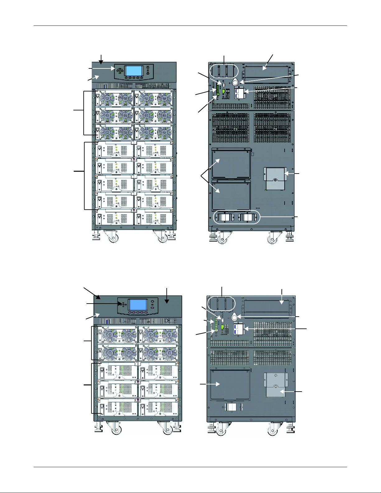
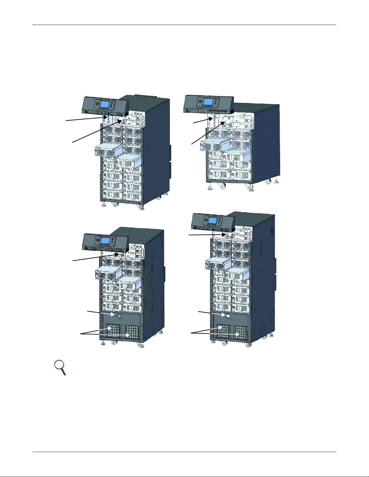
Figure 1 16-bay transformer-free UPS
Manual Bypass Breaker
(under the cover)
Input Breaker
(under the cover)
User Interface
Module
Power, Battery
or Charger
Modules
Battery
Modules
POD
Ports
RS-232
Port
Dry
Contacts
Intelligent Card
Slots
Power Input and
Output Terminals
System Enabling
Breaker
Output Breaker
USB
Port
External Battery
Cabinet
Connector
Front View - Bezels Removed Rear View
POD
Breakers
Manual Bypass
Breaker (under
the cover)
Input Breaker
(under the cover)
User Interface
Module
Power,
Battery or
Charger
Modules
Battery
Modules
POD
Port
RS-232
Port
Dry
Contacts
Intelligent Card
Slots
Power Input and
Output Terminals
System Enabling
Breaker
Output
Breaker
USB
Port
External Battery
Cabinet
Connector
Front View - Bezels Removed
Rear View
System Control Module
(under the cover)
POD Breakers
Product Introduction
Figure 2 10-bay transformer-free UPS
5 SOLA HD® S5KC
™
Page 14
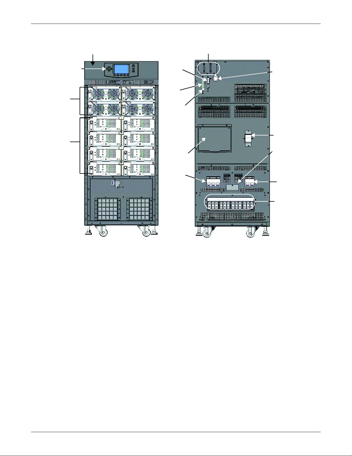
Figure 3 12-bay transformer-based UPS
Manual Bypass Breaker
(under the cover)
User Interface
Module
Power, Battery
or Charger
Modules
Battery
Modules
POD Port
RS-232
Port
Dry
Contacts
Intelligent Card
Slots
Power Input
and Output
Terminals
System Enabling
Breaker
Output
Breaker
USB Port
External Battery
Cabinet
Connector
Front View - Bezels Removed Rear View
POD Breaker
Input
Breaker
Product Introduction
SOLA HD® S5KC
™
6
Page 15
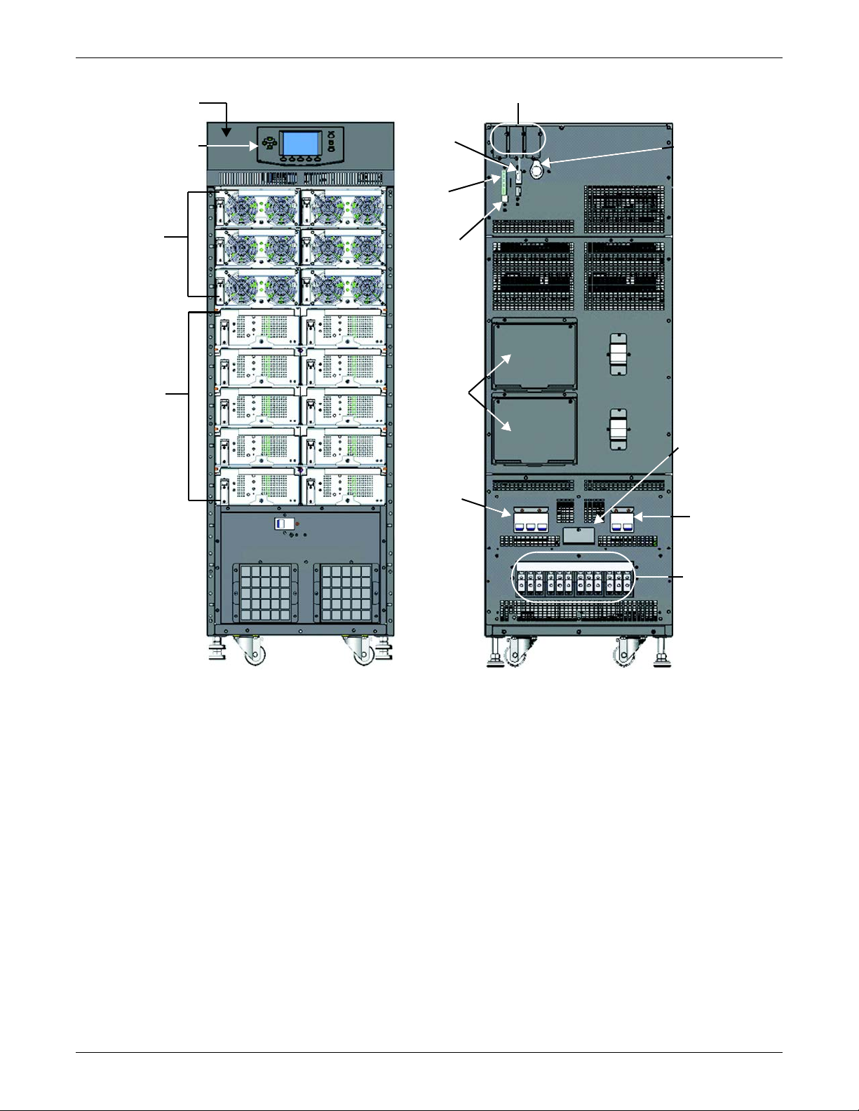
Figure 4 16-bay transformer-based UPS
Manual Bypass
Breaker (under
the cover)
User Interface
Module
Power, Battery
or Charger
Modules
Battery
Modules
Front View - Bezels Removed
POD
Port
RS-232
Port
Dry
Contacts
Intelligent Card
Slots
Power Input
and Output
Terminals
System Enabling
Breaker
Output
Breaker
USB Port
External Battery
Cabinet
Connector
Rear View
Input
Breaker
Product Introduction
7 SOLA HD® S5KC
™
Page 16

1.2 Features
SolaHD S5KC UPS
• Flexible extension of capacity, up to 15 or 20kVA modular power, depending upon frame rating
• N + 1 redundancy, improving availability
• Module design, modules hot-swappable by user
• Redundant intelligent module, providing redundant communication path
• Intelligent battery management
• External large battery assemblies can be connected
• Internal automatic and manual bypass
• Transformer-based UPS frames provide output isolation transformer
• Optional 10A battery charger module
• Continuous system monitoring
• User-friendly interface with audible alarms and event logs
• Supporting hot-pluggable and online update
• Compatible with backup generators
Standard Components
•UPS frame
• User interface module: for comprehensive user indications and programmable controls
• System control modules and system monitor module: for system monitoring and communications
• Power modules: for power conditioning
• Battery modules: for backup power
• Charger module: option for charging batteries and long run time applications
• External battery cabinet: extends system run time
Product Introduction
Communications
• Dry contacts
•IntelliSlot
•USB port
®
communication ports
SOLA HD® S5KC
™
8
Page 17
1.3 Operating Principle
The operating principle of the SolaHD S5KC UPS is shown in Figure 5.
Figure 5 Operating principle diagram
Input
Product Introduction
Manual Bypass
Output
EMI
Filter
Power
Module(s)
EMI
Filter
Output and
Bypass
Contactor
Output
Transformer
Transformer models
Battery
Module(s)
have an output isolating
transformer
System Control
Module
System Monitor
Module
Wiring
Power
Control
User
Interface
Control
Interface
Communication
The SolaHD S5KC UPS is composed of AC input, EMI filter, power module(s), battery module(s), user
interface, control interface, system control module, output and bypass contactor, manual bypass,
output transformer (certain frames only) and AC output.
9 SOLA HD® S5KC
™
Page 18

1.4 Operating Modes
The SolaHD S5KC UPS is a true online double-conversion system, having the following operating
modes:
•Normal Mode
• Backup Mode
•Auto Restart Mode
• Bypass Mode
Normal Mode
The power module rectifiers derive power from a utility AC source and supply regulated DC power to
the inverter. The module’s inverter regenerates precise AC power to supply the connected equipment.
The battery charger is in the power module and maintains a float-charge on the batteries of the UPS;
additionally, the optional charger module can also charge the batteries to maintain a quicker
recharge time for long backup time applications.
Backup Mode
When AC utility fails, the connected equipment is supplied power by the inverter, which obtains
energy from the battery modules. The output power will not be interrupted during the failure or
restoration of the AC utility/mains source.
Auto Restart Mode
Product Introduction
After a power outage and complete battery discharge, and once AC utility is restored, the UPS will
automatically restart and resume supplying power to connected equipment. This feature is enabled at
the factory, but can be disabled by the user. The user can also program two auto restart delay settings
from the LCD:
• Battery capacity level (%)
• Countdown timer
Bypass Mode
The bypass provides an alternate path for power to the connected equipment and operates in the
following manner:
• Automatic: In the event of an internal fault or should the inverter overload capacity be exceeded,
the UPS performs an automatic transfer of the connected equipment from the inverter to the
bypass source.
• Manual: Should the UPS need to be taken out of service for limited maintenance or repair,
manual activation of the bypass will cause an immediate transfer of the equipment from the
inverter to the bypass source.
SOLA HD® S5KC
™
10
Page 19
1.5 Major Components
Manual
Bypass
Breaker
Fan (behind
display bracket)
Manual
Bypass
Breaker
Fan
(behind
display
bracket)
16-Bay Transformer-Free UPS
10-Bay Transformer-Free UPS
16-Bay Transformer-Based UPS12-Bay Transformer-Based UPS
Fan
(behind
display
bracket)
Fan
(behind
display
bracket)
Manual Bypass
Breaker
Manual
Bypass
Breaker
Fans
Fans
This section provides a general description of each component and its functions. Please review this
section carefully, as it will give you a better understanding of how the UPS operates.
1.5.1 UPS Frame
The UPS frames are shown in Figure 6.
Figure 6 UPS frames, bezels removed
Product Introduction
NOTE
In Figure 6, the power module and battery module are extended for illustration purposes only.
Extending more than one module at a time could cause the unit to tip over.
All UPS components are located in the SolaHD S5KC frame. The front of the UPS consists of a series
of metal bezels. By grasping these bezels from the sides and pulling straight out, you can remove the
bezel to reveal the battery/power module bays. The standard-model frame provides cooling fans and a
manual bypass breaker on its top; the transformer-model frame provides a manual bypass breaker on
its bottom and fans on both top and bottom. The user interface module is located above the
power/battery module bays for easy access, operation and for viewing UPS operating information. On
the lower right part of the user interface module, you will see the system control module bays.
11 SOLA HD® S5KC
™
Page 20
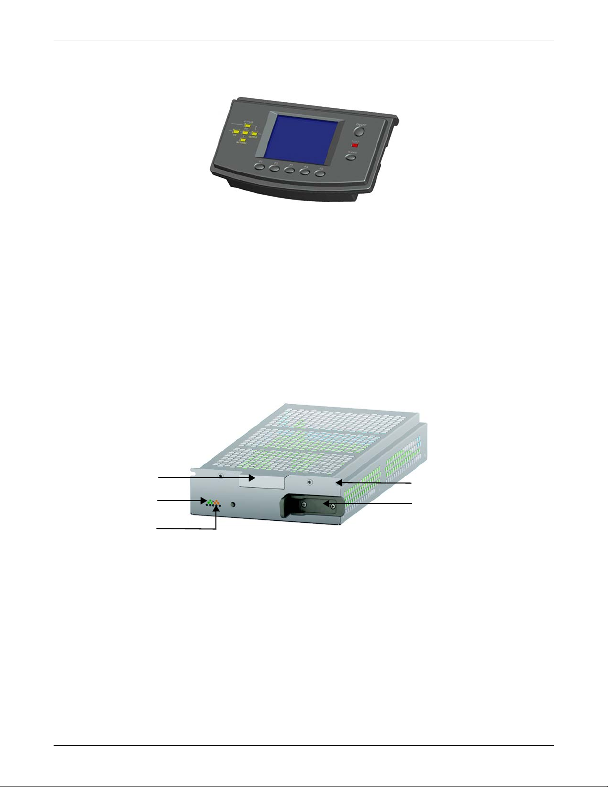
1.5.2 User Interface Module
Handle
Green Status LED
Yellow Fault LED
Securing Hole
Locking Lever
The user interface module is shown in Figure 7.
Figure 7 User interface module
The user interface module is the primary source of communication between the UPS and the user.
The user interface module permits:
• Viewing the UPS status
• Configuring the system
• Reviewing the event log
• Silencing the audible alarm
Refer to 4.0 - Operation and Display Panel for details on operating the user interface module.
1.5.3 System Control Module and System Monitor Module
Product Introduction
The system control module and the system monitor module are the communication backbone of the
UPS. They gather input from all modules and process the data to control the operation of the system,
including monitoring the condition of each module. Except for the silkscreen, the appearance of the
system control module and the system monitor module is as shown in Figure 8.
Figure 8 SolaHD S5KC system control module and the system monitor module
Under normal operation, the green status LED will blink and the yellow fault LED will be Off. For
any other condition, refer to 5.0 - Troubleshooting.
SOLA HD® S5KC
™
12
Page 21
1.5.4 Power Module
Yellow Fault LED
Locking Lever
FRONT VIEW
Fan
Green Status LED
Green Status LED
Yellow Fault LED
Locking Lever
FRONT VIEW
The power module is shown in Figure 9.
Figure 9 SolaHD S5KC power module
Each power module is an independent 5kVA unit, consisting of a power factor corrected rectifier,
battery charger and inverter, with associated monitoring and control circuitry. The modules are
connected in parallel for greater capacity and/or redundancy.
The power modules may be added or replaced on-line with no interruption or danger to the connected
equipment or user.
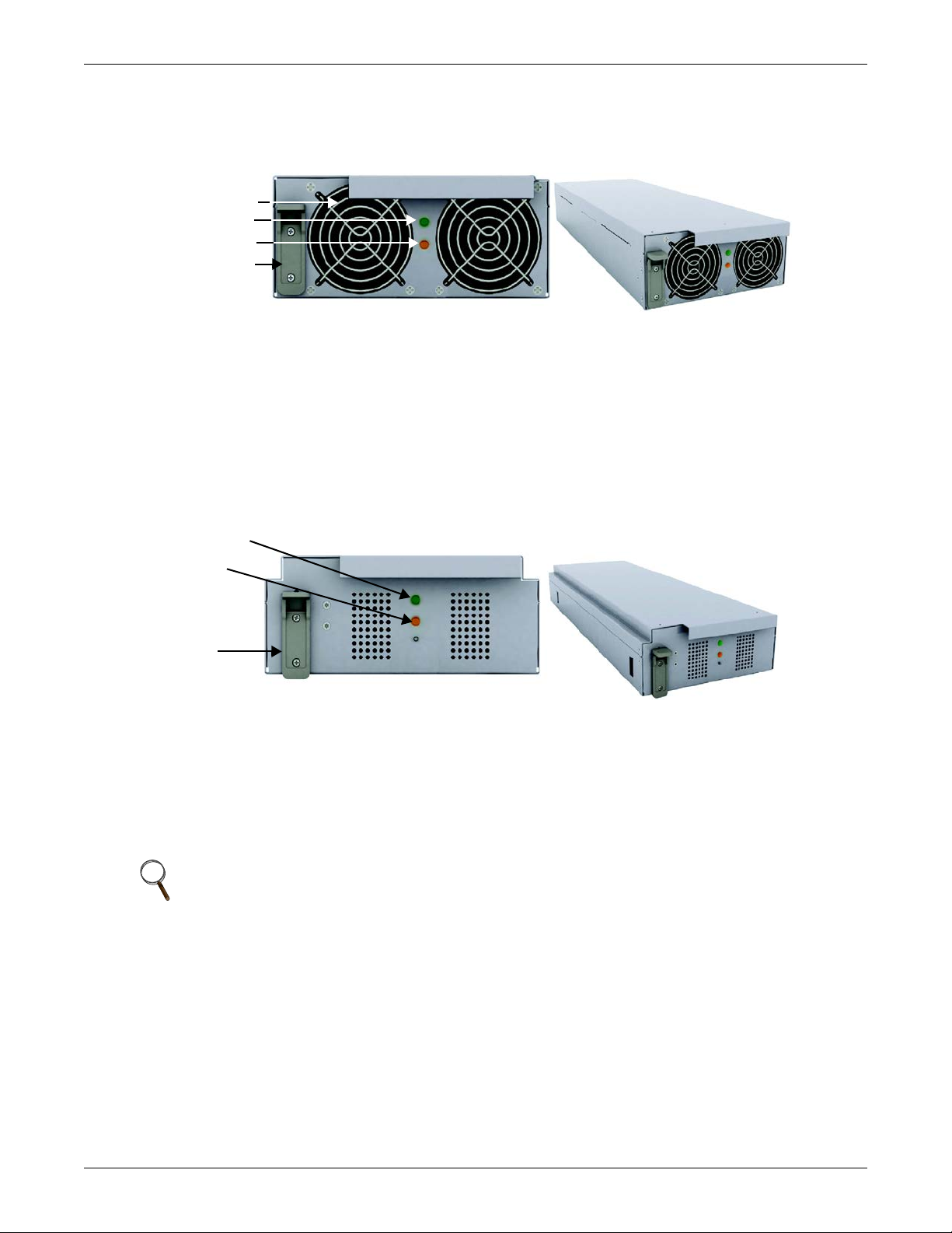
1.5.5 Battery Module
The battery module is shown in Figure 10.
Product Introduction
Figure 10 Battery module appearance
When AC utility fails, the battery module will supply power to the load. Each battery module contains
six individual 12V, valve-regulated lead-acid (VRLA) battery blocks. Two battery modules are
connected in series to form a battery string.
Each battery module has monitoring and controls to isolate the battery module in the event of a
battery failure. The battery strings are connected in parallel to provide backup time and/or
redundancy.
NOTE
Two battery modules must be installed in the same row to make a complete battery string.
The battery modules may be added or replaced on-line with no interruption or danger to the
connected equipment, provided that the UPS is not operating on battery.
Under normal operation, the green status LED will blink continuously and the yellow fault LED will
be Off. For any other condition, refer to 5.0 - Troubleshooting.
13 SOLA HD® S5KC
™
Page 22
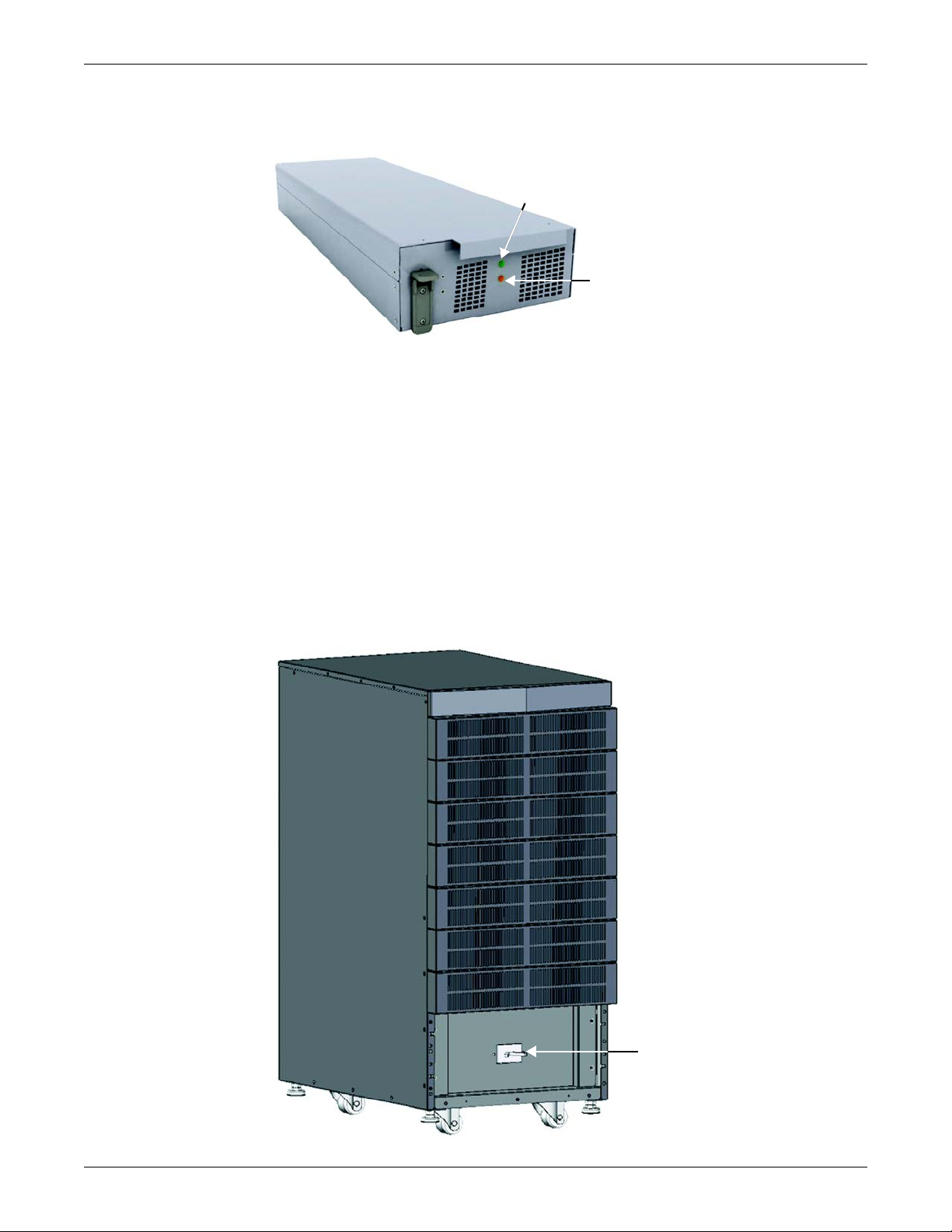
1.5.6 Charger Module
Green Status LED
Yellow Fault LED
EBC Breaker
Figure 11 shows the charger module.
Figure 11 Appearance of the charger module
In AC mains mode, the charger module charges the system battery modules or external battery
cabinet. Each charger module is rated to deliver 10A charging current. The charger module has an
independent control function and maintains real-time communication with the system and the
battery modules to ensure stable charging and fault protection.
The charger module may be added or replaced on-line with no interruption or danger to the user,
connected battery system or connected equipment.
1.5.7 External Battery Cabinet (EBC)
The external battery cabinet is divided into nine rows: the upper seven rows are for use with the
intelligent battery modules, and the lower two are used for overcurrent protection for each battery
cabinet. For normal operation, two battery modules must be inserted in the same row of the frame to
create a complete string. The battery module strings work in parallel to provide longer backup time
for the UPS. A SolaHD S5KC can be configured with, at most, four external battery cabinets.
An external battery cabinet is shown in Figure 12.
Product Introduction
Figure 12 External battery cabinet
SOLA HD® S5KC
™
14
Page 23
2.0 INSTALLATION
12" (305mm)
39" (1000mm)
This chapter describes UPS installation, including installation preparation, unloading the UPS,
mechanical installation, installing modules and cable connection.
2.1 Unpacking Inspection
Upon receiving the UPS, uncrate it and conduct the following checks:
• Inspect the UPS appearance for shipping damage. Report any shipping damage to the carrier and
send a copy to your Emerson
• Check against the delivery list to ensure that the package contains the correct number and type of
accessories. If there is any discrepancy, contact the distributor immediately.
2.1.1 Installation Environment
NOTE
Operating the UPS in temperatures above 77°F (25°C) will reduce battery life.
The UPS environment must be free of conductive contaminants and excessive moisture (water and
condensation), flammable vapors, chemical fumes, corrosive gases and liquids.
2.1.2 Installation Tools
The tools required to properly set up your UPS are listed below:
• Pallet jack
• 17mm (11/16") wrench or socket
• 13mm (1/2") wrench or socket
• 10mm wrench or socket
• #1 and #3 Phillips screwdrivers
• Torque wrench
®
representative.
Installation
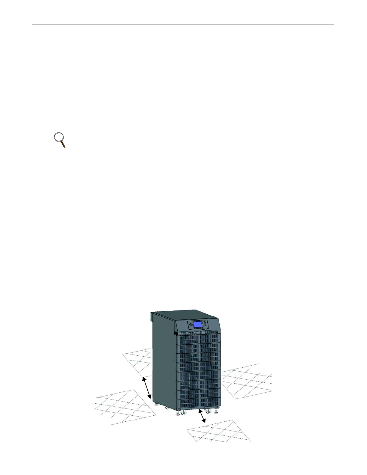
2.1.3 Installation Site
Consider the weight and size of the SolaHD S5KC when deciding where to install the unit. Verify that
the floor can support the weight of a fully loaded unit, any accessories and external cabinets.
Verify that the UPS will be in a well-ventilated area with at least 12 inches (305mm) clearance
behind it. The UPS is air-cooled, utilizing internal fans. Air is drawn into the front of the UPS and is
exhausted through ventilation grilles in the back. The UPS should also have at least 39 inches (1m)
clearance in front for service and to meet many local and national building codes.
Figure 13 Front and rear installation clearances
15 SOLA HD® S5KC
™
Page 24
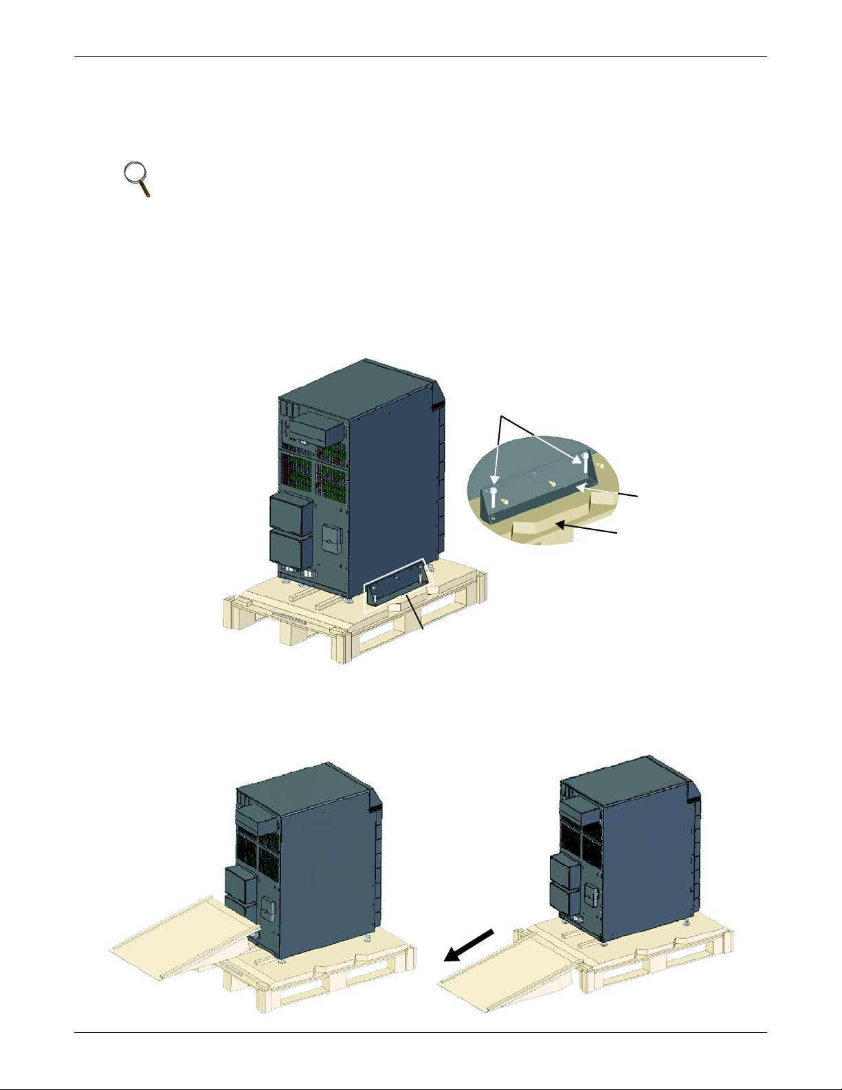
2.2 Unloading the UPS
Sola S5KC
Detail A
A
Pallet
Mounting Bolts
(2 each side)
Mounting Bracket
(1 each side)
The unit frame is bolted to the shipping pallet to ensure safety during shipping. Emerson
recommends keeping the unit bolted to the pallet and using a pallet jack to transport the unit to its
installation location.
NOTE
This UPS is very heavy. At least two people should assist in unloading it from the pallet.
To unload the UPS:
1. Move the UPS to its installation site and remove the package paper.
2. Use a 17mm (11/16") wrench, to remove the four mounting bolts from the pallet brackets (see
Figure 14).
3. Remove the mounting brackets from the UPS with a 10mm wrench or socket or a #3 Phillips
screwdriver.
Figure 14 Remove the mounting brackets
Installation
4. Raise the four leveling feet to provide clearance between the pallet and the UPS frame.
5. Connect the ramp to the UPS pallet, as shown in Figure 15.
6. Roll the UPS slowly down the ramp until it is on a level surface, as shown in Figure 15.
Figure 15 Connect the ramp and remove UPS
SOLA HD® S5KC
™
16
Page 25
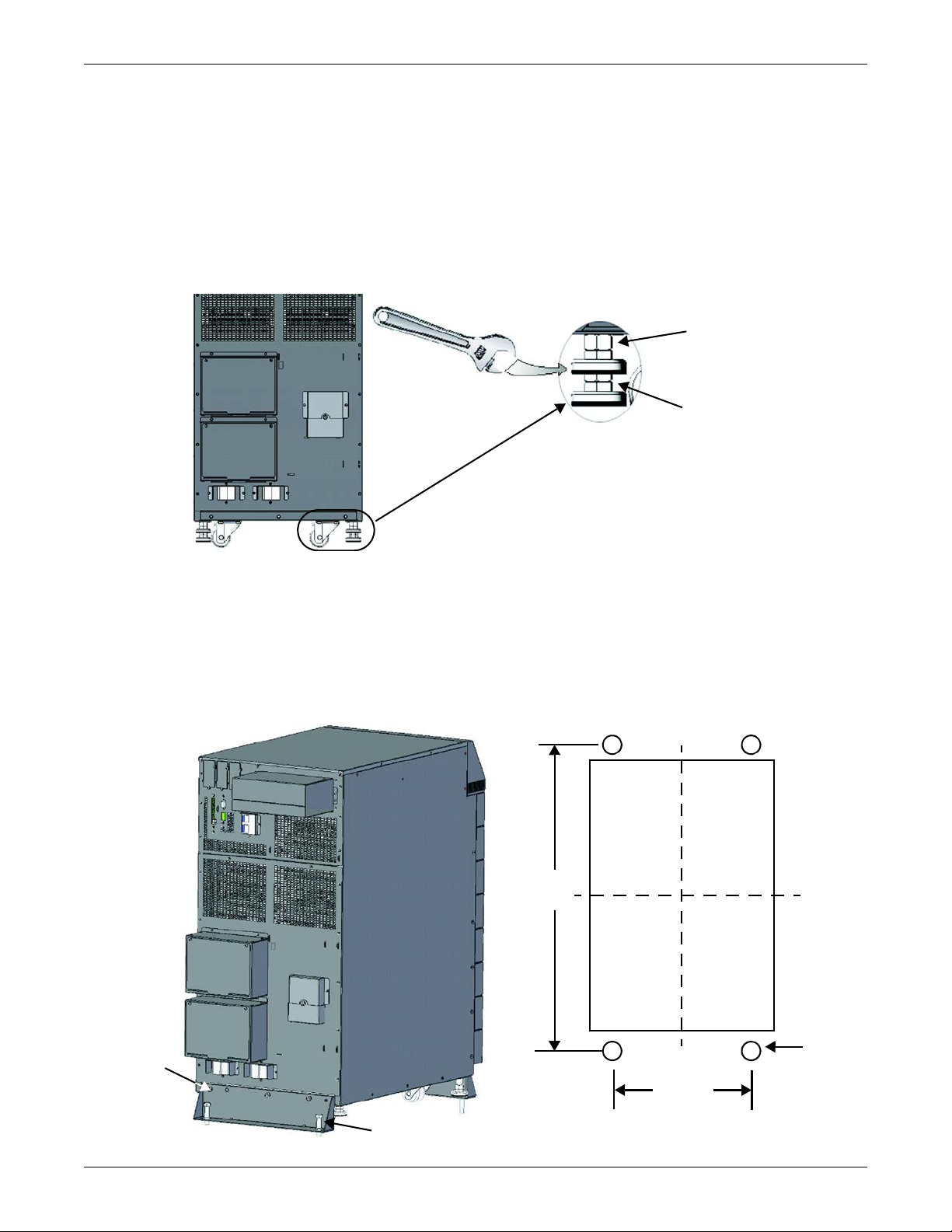
2.3 Mechanical Installation
Lower nut is bonded to
leveling foot; used to raise
and lower foot
Upper nut is threaded on
leveling foot; used to hold
foot height
716mm
(28.19")
340mm
(13.39")
M10
screw
Floor-Mounting Hole Layout
Mounting Bolt
Mounting
Bracket
Two installation modes are available for the SolaHD S5KC UPS: tower installation and rack
installation.
2.3.1 Tower Installation
1. Once the UPS is in the desired location, adjust the leveling feet to secure its position, as shown in
Figure 16.
a. Use an open end wrench to turn the lower nut to raise or lower the leveling foot.
b. After the unit is level, tighten the upper nut against the frame to prevent the height from
changing.
Figure 16 Adjust the leveling feet
Installation
2. For added stability or earthquake-resistant installations, the shipping brackets can be used to
secure the unit to the floor.
a. Drill holes 10.3mm (13/32") in the floor for stationary mounting; these will accommodate the
mounting bolts removed from the pallet. Refer Figure 17 for the layout.
b. Use the mounting screws to install the mounting brackets on the front and rear of the UPS.
c. Secure the mounting brackets to the floor with the mounting bolts (see Figure 17).
For greater stability, use a higher-grade bolt.
Figure 17 Installation position and drilling hole dimensions for stationary mounting
17 SOLA HD® S5KC
™
Page 26
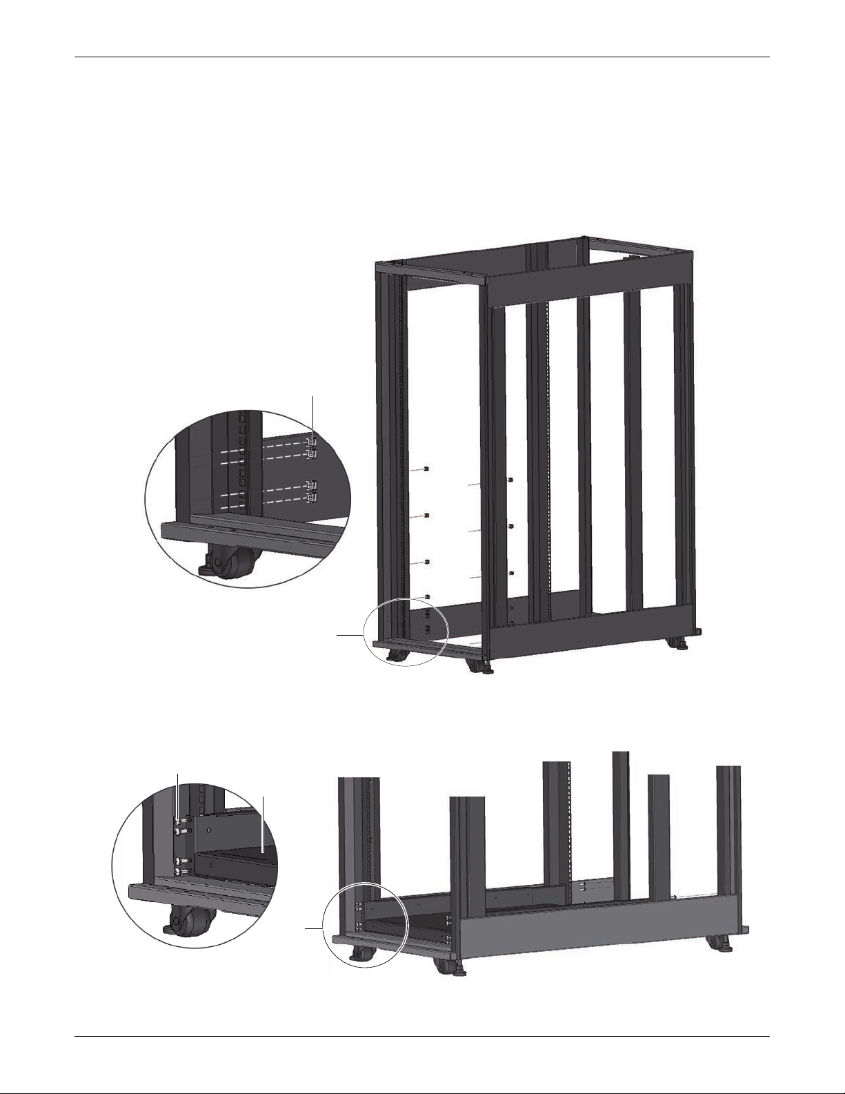
2.3.2 Rack Installation
A
Detail A
Floating Nut
B
Detail B
Screw,16 places
Tray
1. Install the cage nuts on the corresponding positions in the rack, as shown in Figure 18.
a. Install cage nuts in the two lower square holes of 1U space and in the two upper square holes
of 2U space of all four rack posts. These cage nuts will secure the optional shelf that will
support the weight of the SolaHD S5KC.
b. Install a cage nut in the middle square hole of 4U, 6U, 10U, 12U spaces, respectively, again in
all four posts. The cage nuts will help secure the UPS in the rack.
Figure 18 Install cage nuts
Installation
2. Install the rack-mount shelf on the corresponding position between 1U space and 2U space on the
Figure 19 Install the tray
3. Install the guide rails (ramp) in the mounting slot at the front of the tray, as shown in Figure 20.
SOLA HD® S5KC
bottom of the rack, as shown in Figure 19.
™
18
Page 27
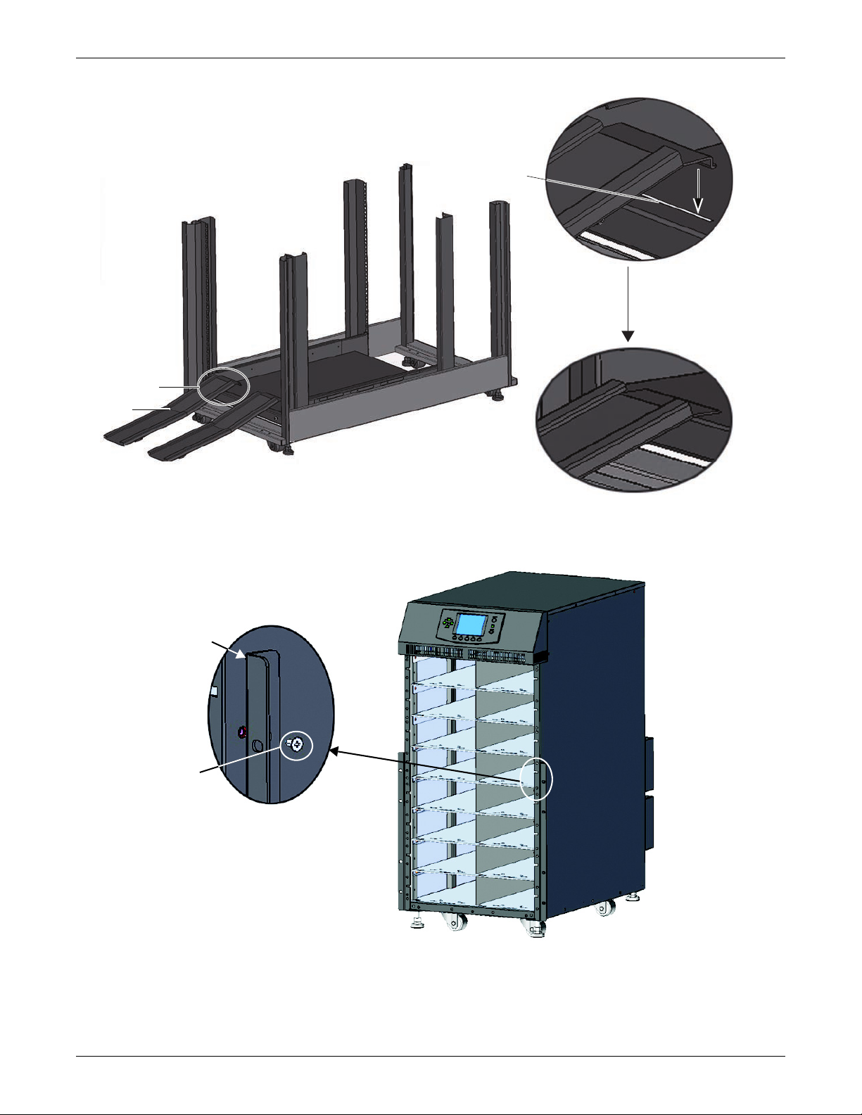
Figure 20 Install the guide rails
C
Guide
Rail
Mounting Slot
Insert one end
of the guide rail
into the mounting
slot on the tray
Detail C
Bracket
Screw
(8 Places)
Detail Area
Installation
4. Unscrew the 10 screws on the front of the two side panels of the UPS frame.
5. Use those screws to attach the brackets to each side of the UPS frame, as shown in Figure 21.
Figure 21 Install the brackets
19 SOLA HD® S5KC
™
Page 28
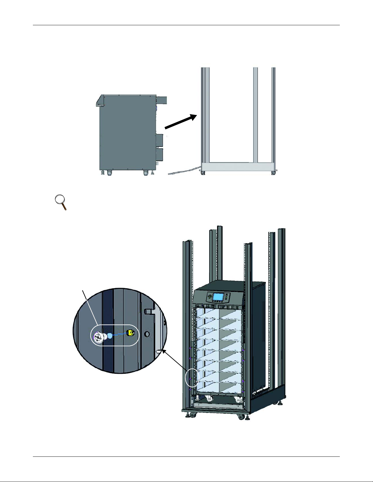
6. Push the SolaHD S5KC frame slowly into the enclosure from the front, as shown in Figure 22. The
Push the
UPS frame
into the
rack.
Front
of
Rack
Front
of
UPS
Panel
Screw
(8 Places)
Detail Area
rear of the UPS goes into the rack first when installing through the front of the rack.
Figure 22 Push the UPS frame into the rack
7. Use eight panel screws to secure the UPS frame to the rack posts, as shown in Figure 23.
Installation
NOTE
It might be necessary to use the leveling feet to get the holes to align
Figure 23 Fix the UPS frame
SOLA HD® S5KC
™
20
Page 29
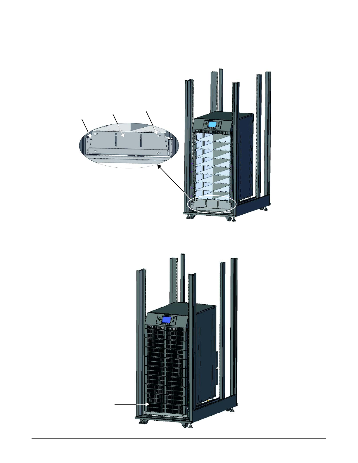
8. Use four screws to install the metal plate (accessory in the rack-mount kit) on the corresponding
Square Hole
(2 Places)
Detail Area
Metal Plate
Mounting Screw
(4 Places)
Bezel
position on the lower front part of the UPS frame
9. Insert the provided bezel into the square holes of the metal plate, as shown in Figures 24 and 25.
Figure 24 Install the metal plate
Installation
The installation is complete, as shown in Figure 25.
Figure 25 Installation completed
21 SOLA HD® S5KC
™
Page 30
2.4 Module Installation
1. Push module slowly into
the bay until it is 1/3 in.
2. Raise the face
of the module.
4. Push module quickly and
firmly into the bay.
3. Continue pushing module slowly
until about 2" (50mm) remains out.
The SolaHD S5KC ships from the factory configured (modules prepopulated) and tested as a system
to the customer’s requirements. If any modules were removed to facilitate ease of installation, follow
the steps below to reinsert them properly.
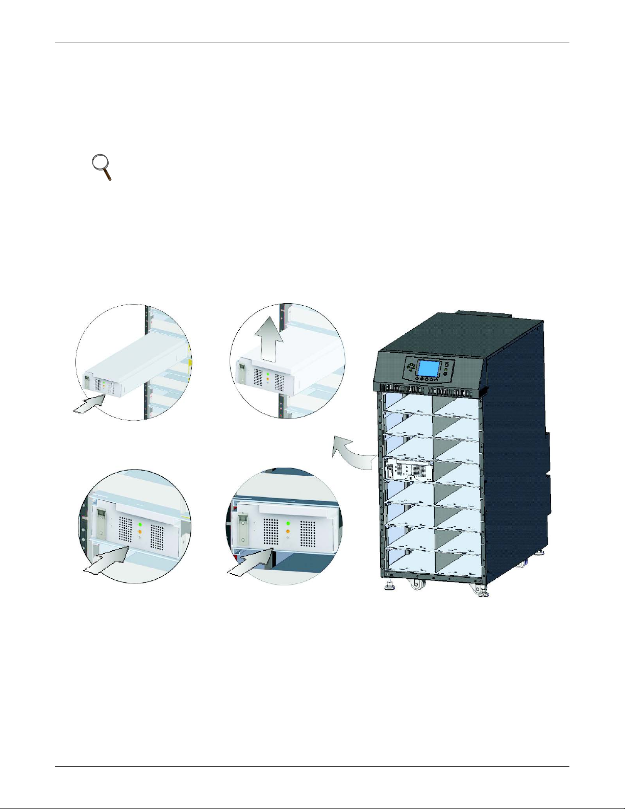
2.4.1 Installing Power Module, Battery Module and Charger Module
1. Lift module to appropriate bay, resting end of module on bay shelf.
NOTE
Use caution not to rest the module on any of the bezels, this could damage the bezel.
Two battery modules must be installed in the same row to complete the battery string.
2. Push the module into the bay slowly. The module will be locked until 1/3 is in.
a. At this point, lift the module up and continue pushing it until about 5cm of the module is still
out of the bay.
b. Push it firmly and smoothly to ensure that the module is fully inserted, as shown in
Figure 26.
Figure 26 Insert the power module, battery module and charger module
Installation
3. Use a #2 Phillips screwdriver to install the module-securing bracket, and then press the lever
down into the bracket, as shown in Figure 27.
SOLA HD® S5KC
™
22
Page 31

Figure 27 Lever and fastener
Locking Lever
Fastener
Pull Out
Press
Down
Before Pressing Locking Lever
(Side View)
After Pressing Locking Lever
(Side View)
Installation
4. Replace the small bezels.
NOTE
If the lever of the module cannot be pressed down smoothly, remove the module and reinstall it.
23 SOLA HD® S5KC
™
Page 32

2.4.2 Installing System Control and System Monitor Modules
Large Display Bezel
User Interface Module
NOTICE
Risk of unintended shutdown. Can cause equipment damage.
Do not remove both the control and the monitor modules at the same time. Removing both the
control module and monitor module at the same time will cause the UPS to shut down and
remove power from the load. Replace these modules one at a time.
1. Remove the display bezel and the user interface (LCD) module on top of the frame, as shown in
Figure 28.
Figure 28 Remove large display bezel and user interface module
Installation
2. Push the module slowly until about 1cm of the module is still out of the bay, and then press it
firmly to ensure that the module is fully inserted, as shown in Figure 29.
Figure 29 Insert the System Control and System Monitor module
SOLA HD® S5KC
™
24
Page 33

3. Use a #2 Phillips screwdriver to install the screws into the holes on each end.
!
Mounting
Hole
Lever
Mounting
Hole
4. Slide the lever toward the right, as shown in Figure 30.
Figure 30 Lever and fastener on System Control and System Monitor Module
Press and Slide
to the Right
Pull
Out
Before Pressing
Lever
After Pressing
Lever
Installation
5. Replace the LCD module and display bezel.
2.5 Cable Connection
WARNING
Risk of electric shock. Can cause injury or death.
Disconnect local and remote power supplies before working within.
Read this section thoroughly before attempting to install wiring to this unit.
Ensure that all the UPS input sources are disconnected off before attempting to install wiring
to this unit.
This UPS cables should be connected by a properly trained and qualified electrician.
Refer to the unit model number in Table 2 to determine which instructions to use for installation.
Table 2 Cable connection method reference
UPS Model #
Digits 1-4
S5KCA 10 Bay Transformer-free 2.5.1
S5KCB 16 Bay Transformer-free 2.5.1
S5KCC 12 Bay Transformer-based 2.5.2
S5KCD 16 Bay Transformer-based 2.5.2
S5KCE 10 Bay Transformer-free 2.5.3
S5KCF 16 Bay Transformer-free 2.5.3
Frame Type
Manual
Section
25 SOLA HD® S5KC
™
Page 34

2.5.1 Transformer-Free UPS Cable Connection
16-Bay SolaHD S5KC
No Transformer
10-Bay SolaHD S5KC
No Transformer
A junction box is factory-installed on each model of the SolaHD S5KC to ease cable connection.
Select the appropriate input cables according to Table 3 and Table 4 based on the UPS rating and
mains frequency; however, it is recommended that you size the over current protection and wiring for
the frame rating to easily allow upgrades to the UPS system.
Table 3 Input cable selection list—60Hz
Input voltage - 200VAC Input voltage - 208VAC Input voltage - 240VAC
Maximum
System
Rated Load
5kVA 27A 50A 26A 50A 23A 50A
10kVA 53A 63A 51A 63A 45A 63A
15kVA 80A 100A 77A 100A 67A 100A
20kVA 106A 125A 102A 125A 90A 125A
The power input and output terminals accept a maximum cable cross-sectional area of 35mm2 (2AWG); the minimum cable
cross-sectional area is 16mm
Use of 90°C copper wire is recommended
Table 4 Input cable selection list—50Hz
Maximum
System
Rated Load
5kVA 25A 50A 24A 50A 23A 50A
10kVA 49A 63A 47A 63A 45A 63A
15kVA 73A 100A 70A 100A 67A 100A
20kVA 97A 125A 93A 125A 90A 125A
The power input and output terminals accept a maximum cable cross-sectional area of 35mm2 (2AWG); the minimum cable crosssectional area is 16mm2 (6AWG); the rated torque is 4.52Nm (40 in-lb).
90°C copper wire recommended
Maximum
Current in
UPS Mode
Input Voltage - 220VAC Input Voltage - 230VAC Input Voltage - 240VAC
Maximum
Current in
UPS Mode
Recommended
Input Protection
Circuit Breaker
2
(6AWG); the rated torque is 4.52Nm (40 in-lb).
Recommended
Input Protection
Circuit Breaker
Maximum
Current in
UPS Mode
Maximum
Current in
UPS Mode
Recommended
Input Protection
Circuit Breaker
Recommended
Input Protection
Circuit Breaker
Maximum
Current in
UPS Mode
Maximum
Current in
UPS Mode
Installation
Recommended
Input Protection
Circuit Breaker
Recommended
Input Protection
Circuit Breaker
To connect the cable:
NOTE
Input and output cables must be run in separate conduit before cable connection.
1. Remove the knockouts at the junction box (see Figure 31) and pull the cables through them,
leaving some slack for installation.
Figure 31 Knockouts
SOLA HD® S5KC
™
26
Page 35

2. Connect the cables to the corresponding terminal of the power input and output terminals.
PE 2 1 PE 4 3 2 1
OUTPUT INPUT
200 V/208V/220V/230V/240V
200V /208V/220V/230V/240V
PE 2 1 PE 4 3 2 1
OUTPUT INPUT
200V/208V/220V/230V/240V
380V/400V/415V
3. Tighten the screws to 4.52Nm (40 in-lb) with a 13mm (1/2") torque wrench.
4. Respectively, secure the conduit of the input/output cables through the cable bridges on the rear
panel of the UPS (see Figure 31).
The connection methods in the single-phase input mode and the 3-phase input mode are shown in
Figures 32 and 33, respectively. Installation of the factory-provided copper bar is essential in the
single-phase input mode. The copper busbar is in the accessory bag included with the UPS.
Figure 32 Connection in single-phase input
Installation
Figure 33 Connection in 3-phase input
27 SOLA HD® S5KC
™
Page 36

Table 5 Key to Figures 32 and 33 UPS wiring
System
Voltage
200 60 L1 * L1 * L1 * L2 GND L1 L2 GND
208 60 L1 * L1 * L1 * L2 GND L1 L2 GND
220 60 L1 * L1 * L1 * L2 GND L1 L2 GND
230 60 L1 * L1 * L1 * L2 GND L1 L2 GND
240 60 L1 * L1 * L1 * L2 GND L1 L2 GND
200 50 L * L * L * N PE L N PE
220 50 L * L * L * N PE L N PE
230 50 L * L * L * N PE L N PE
240 50 L * L * L * N PE L N PE
380 50 L1 L2 L3 N PE L N PE
400 50 L1 L2 L3 N PE L N PE
415 50 L1 L2 L3 N PE L N PE
* This connection requires the factory-provided three-position busbar to connect the three terminal block positions
System Nominal
Frequency
1234PE 12PE
Input Terminal Block Output Terminal Block
2.5.2 Transformer-Based UPS Cable Connection
NOTE
After the output transformer is installed, if the startup is on bypass, the UPS has a six-cycle
inrush current that is up to 20 times the rated output current. This must be taken into account
when selecting the input overload protection device at the AC input supply distribution point.
®
To avoid random tripping on startup, Emerson
protected with a circuit breaker capable of withstanding this initial inrush (the MCB is
derated according to the D curve or TYPE 4).
recommends that the AC input supply be
Installation
This UPS is fitted with EMI filters. Earth leakage current is less than 40mA. Transient and
steady state earth leakage currents may occur when starting the UPS. This should be taken
into account when selecting transient RCCB or RCCD (leakage current devices of the UPS and
load).
The MCB of the AC power supply connected to the UPS input must bear this warning:
Disconnect the connection with UPS before maintaining this circuit
The warning is required because the UPS has no autofeeding protection device.
The UPS grounding should be in accordance with local regulations.
A junction box is factory-installed on all models of the SolaHD S5KC to ease cable connection.
Select the appropriate input cables according to Table 6 and Table 7 based upon the UPS rating and
mains frequency. Emerson recommends sizing the frame’s overcurrent protection and wiring to
permit easier UPS system upgrades.
Table 6 Input cable selection for transformer-based frames (60 Hz)
Input Voltage - 200VAC Input Voltage - 208VAC Input Voltage - 240VAC
Maximum
System Rated
Load
5kVA 27A 50A 26A 50A 23A 50A
10kVA 53A 63A 51A 63A 45A 63A
15kVA 80A 100A 77A 100A 67A 100A
20kVA 106A 125A 102A 125A 90A 125A
The power input and output terminals accept a maximum cable cross-sectional area of 70mm2 (2/0AWG); the minimum cable
cross-sectional area is 16mm
90°C copper wire recommended.
Maximum
Current in
UPS Mode
Recommended
Input Protection
Circuit Breaker
2
(6AWG). The rated torque is 12.43Nm (110 in-lb).
Maximum
Current in
UPS Mode
Recommended
Input Protection
Circuit Breaker
Maximum
Current in
UPS Mode
Recommended
Input Protection
Circuit Breaker
SOLA HD® S5KC
™
28
Page 37

Table 7 Input cable selection for transformer-based frames (50 Hz)
Jumper
34GEC 2 1 1 2 3
INPUT
208V Tap
OUTPUT
12PE
240V Tap
208VAC
PE
Jumper
34GEC 21123
INPUT
208V Tap
OUTPUT
12PE
240V Tap
240VAC
PE
Input Voltage - 220VAC Input Voltage - 230VAC Input Voltage - 240VAC
Maximum
System Rated
Load
Maximum
Current in
UPS Mode
Recommended
Input Protection
Circuit Breaker
Maximum
Current in
UPS Mode
5kVA 25A 50A 24A 50A 23A 50A
10kVA 49A 63A 47A 63A 45A 63A
15kVA 73A 100A 70A 100A 67A 100A
20kVA 97A 125A 93A 125A 90A 125A
The power input and output terminals accept a maximum cable cross-sectional area of is 70mm2 (2/0AWG); the minimum cable
cross-sectional area is 16mm
90°C copper wire recommended.
2
(6AWG). The rated torque is 12.43Nm (110 in-lb).
Configuring the Bypass Voltage
The UPS bypass voltage is factory-set and the copper busbar jumper has been factory-installed. If the
jumper setting does not match the input source, the bypass voltage jumper may need to be changed to
ensure the correct output voltages are provided when operating in bypass mode. Refer to Table 9 for
the proper setting location according to the AC mains voltage available and to Figures 34 and 35 for
the jumper setting location.
Figure 34 Setting bypass voltage jumper (default: 208VAC)
Recommended
Input Protection
Circuit Breaker
Maximum
Current in
UPS Mode
Installation
Recommended
Input Protection
Circuit Breaker
Figure 35 Setting bypass voltage jumper (200/220/230/240VAC)
29 SOLA HD® S5KC
™
Page 38

Configuring the Neutral/Earth Jumper
Neutral/Earth Jumper
34GEC 2 1 1 2 3
INPUT
208V T ap
OUTPUT
12PE
240V T ap
PE
16-Bay SolaHD S5KC
With Transformer
12-Bay SolaHD S5KC
With Transformer
The UPS contains an isolation transformer that generates a neutral conductor for the connected load.
The UPS is a separately derived source and contains a neutral/earth jumper. A factory-installed
neutral/earth jumper copper bar may require removal to comply with local codes and regulations.
Figure 36 Configuring the neutral/earth jumper
Connecting Cables
To connect the cable:
Installation
NOTE
Input and output cables must be run in separate conduit before cable connection.
1. Remove the knockouts at the junction box (see Figure 37) and pull the cables through them,
leaving some slack for installation.
Figure 37 Knockouts
2. Connect the cable to the corresponding terminal of the power input and output terminals. Using a
torque wrench, tighten the screws to 12.43Nm (110 in-lb). The connections are shown in
Figure 38.
SOLA HD® S5KC
™
30
Page 39

Figure 38 Connection method
34GEC 2 1 1 2 3
INPUT
208V Tap
OUTPUT
12PE
240V Tap
PE
200V/208V/
220V/230V/240V
Factory-
supplied
jumper
1-3: 240V; 2-3: 208V; 1-4: 120V;
3-4: 120V (When the output voltage is
set to 240V through LCD)
Refer to Table 7 for configuring the output cable. For standard voltages, make the connections shown
in Table 9.
Table 8 Key to Figure 38 UPS input wiring
System
System
Voltage
Nominal
Frequency
200 60 L1 L2 GND
208 60 L1 L2 GND
220 60 L1 L2 GND
230 60 L1 L2 GND
240 60 L1 L2 GND
200 50 L N PE
220 50 L N PE
230 50 L N PE
240 50 L N PE
Table 9 Key to Figure 38 UPS output wiring
Set Output
Output
Voltage
200/100 200 — OK 100 100
220/110 220 — OK 110 110
230/115 230 — OK 115 115
220/127 220 OK — 127 127 220
240/120 240 — OK 120 120 208 240
208/120 208 OK — 120 120 208 240
If the bypass voltage jumper copper bar is connected incorrectly, the system will report a fault alarm.
When wiring to single-phase panels, connect to output terminals 1, 3, 4 and PE (GND) only.
Voltage
by LCD
Input Terminal Block
12 PE
Bypass Voltage Jumper Output Voltage (Between Terminals)
208V TAP
(1-2)
240V TAP
(2-3) 1-4 3-4 2-3 1-3
173
(Do Not Use)
190
(Do Not Use)
199
(Do Not Use)
200
220
230
254
(Do Not Use)
Installation
Table 10 shows the maximum load capacity of the output winding of the transformer-based UPS.
Table 10 Maximum load capacity of the output winding
16-bay Transformer-based UPS 10 10 20 20
10-bay Transformer-based UPS 7.5 7.5 15 15
UPS Model
Maximum Output Capacity, kVA
(Between Terminals)
1-4 3-4 2-3 1-3
31 SOLA HD® S5KC
™
Page 40

2.5.3 Transformer-Free UPS—Dual Inverter Frames
10-Bay SolaHD S5KC
No Transformer
16-Bay SolaHD S5KC
No Transformer
A junction box is factory-installed on all models of the SolaHD S5KC to ease cable connection.
Select the appropriate input cables according to Tables 11 and 12 based on the UPS rating and
mains frequency. Emerson recommends sizing the overcurrent protection and wiring for the frame
rating for easing upgrades to the UPS system.
Table 11 Input cable selection for transformer-free dual inverter frames (50/60 Hz)
Input Voltage – 200/100VAC Input Voltage – 208/120VAC Input Voltage – 240/120VAC
Maximum
System Rated
Load
5kVA 28A 50A 27A 50A 27A 50A
10kVA 56A 63A 54A 63A 54A 63A
15kVA 84A 100A 80A 100A 80A 100A
20kVA 112A 125A 107A 125A 107A 125A
The power input and output terminals accept a maximum cable cross-sectional area of 35mm2 (2AWG); the minimum cable crosssectional area is 16mm
90°C copper wire is recommended.
Table 12 Input cable selection for transformer-free dual inverter frames (50/60 Hz)
Maximum
System Rated
Load
5kVA 28A 50A 28A 50A 27A 50A
10kVA 56A 63A 56A 63A 54A 63A
15kVA 84A 100A 84A 100A 80A 100A
20kVA 112A 125A 112A 125A 107A 125A
The power input and output terminals accept a maximum cable cross-sectional area of 35mm2 (2AWG); the minimum cable
cross-sectional area is 16mm
90°C copper wire is recommended.
Maximum
Current in
UPS Mode
2
(6AWG); and the rated torque is 4.52Nm (40 in-lb);.
Input voltage – 220/110VAC Input voltage – 230/115VAC Input voltage – 220/127VAC
Maximum
Current in
UPS Mode
Recommended
Input Protection
Circuit Breaker
Recommended
Input Protection
Circuit Breaker
2
(6AWG); and the rated torque is 4.52Nm (40 in-lb);
Maximum
Current in
UPS Mode
Maximum
Current in
UPS Mode
Recommended
Input Protection
Circuit Breaker
Recommended
Input Protection
Circuit Breaker
Maximum
Current in
UPS Mode
Maximum
Current in
UPS Mode
Installation
Recommended
Input Protection
Circuit Breaker
Recommended
Input Protection
Circuit Breaker
To connect the cable:
NOTE
Input and output cables must be run in separate conduit before cable connection.
1. Remove the knockouts at the junction box (see Figure 31) and pull the cables through them,
leaving some slack for installation.
Figure 39 Knockouts
2. Connect the cables to the corresponding terminal of the power input and output terminals.
3. Tighten the screws to 4.52Nm (40 in-lb) with a 13mm (1/2 in) torque wrench.
SOLA HD® S5KC
™
32
Page 41

4. Respectively secure the input/output cables through the cable bridges on the rear panel of the
Cable
Bridge
Cable
Bridge
UPS (see Figure 40).
Figure 40 Secure cables on cable bridges
The connections for the single-phase input mode and the 3-phase input mode are shown in Figure 32
and Figure 33, respectively. The copper jumper busbar is essential for the single-phase input mode.
Figure 41 Wiring connections
Installation
OUTPUT INPUT
PE N L2 L1 PE N L2 L1
33 SOLA HD® S5KC
™
Page 42

2.5.4 Connecting External Battery Cabinet
!
Up to four external battery cabinets may be connected to the SolaHD S5KC Series UPS to provide
longer battery run times.
The external battery cabinet (EBC) requires the use of one of the optional EBC cable kits for
connection to the UPS. The optional cable kits each contain the power and communication cables
required for proper operation and monitoring of the battery modules. The standard cable kit lengths
are 1, 3, and 5 meters (3.2, 9.8 and 16.4 ft.) to accommodate different site installation requirements.
To connect an external battery cabinet:
1. Verify that the EBC DC circuit breaker is open. The circuit breaker is on the front bottom of the
EBC frame behind the bottom two bezels.
2. Connect one end of the battery cable to the external battery connector on the rear of the UPS
frame.
3. Connect the other end to the closest corresponding port on the rear of the EBC frame, as shown in
Figures 42 and 43.
4. Install and tighten the grounding screw on the battery cable assembly, on both the UPS and EBC
ends. This screw also secures the cable assembly to the frames to prevent accidental
disconnection.
5. For new systems that included an EBC, the EBC communication card should already be installed
in the UPS frame (IntelliSlot Port #3, typically). If it is not already in the UPS frame, obtain the
EBC communication card and insert it into any open IntelliSlot port (preferably Port #3). Connect
the provided EBC communication cable to the UPS and EBC as shown in Figures 42 and 43.
6. Check the EBC DIP switch settings on the top rear of each EBC frame. Verify they are set
correctly according to Table 13.
7. Close the EBC DC circuit breaker and replace the bezels back onto the EBC.
Installation
WARNING
Risk of hazardous voltage between UPS frames. Can cause damage to equipment, injury and
death.
Failure to open the EBC DC circuit breaker before connecting or disconnecting the battery
cable between the UPS and EBC frames can result in hazardous voltages being present
between the frames.
SOLA HD® S5KC
™
34
Page 43

Figure 42 Connecting external battery cabinet to a transformer-free UPS
Communication
Cable
Battery
Cable
Battery CabinetSolaHD S5KC
Battery Cabinet
SolaHD S5KC
Communication
Cable
Battery
Cable
Installation
Figure 43 Connecting external battery cabinet (transformer- based UPS)
After connecting the external battery cabinet, use the user interface to determine the number of
external battery cabinets, as shown in Figure 44.
35 SOLA HD® S5KC
™
Page 44

Figure 44 Battery screen
If the number displayed is not consistent with the actual installation number of external battery
cabinets:
• Ensure each external battery cabinet contains two battery modules installed on the same row and
both have the locking levers in the locked position.
• Ensure the IntelliSlot
inserted in the connectors.
• Determine that the DIP switch setting of each battery cabinet is correct using the following table
Table 13 EBC DIP switch settings
External Battery
Cabinet Number
EBC #1 UP UP
EBC #2 Down UP
EBC #3 UP Down
EBC #4 Down Down
®
EBC card is installed properly and the communication cables are fully
DIP Switch Setting
12
Installation
2.5.5 Connecting Integrated Power Output Distribution (POD)
The rear panel of the SolaHD S5KC UPS provides the capability to add integrated distribution outlets
(PODs) as an option to allow direct AC power connection of the supported equipment to the UPS.
These PODs are intended to allow the user to install and even change distribution, if necessary as
SOLA HD® S5KC
™
36
Page 45

Installation
equipment changes, while the UPS is still providing power. Follow these steps to properly and safely
add or change the optional PODs.
1. Ensure that the POD breaker is in the Off position.
NOTE
This is the breaker located near the POD port.
2. Using a Phillips screwdriver, remove the two screws that are at the top of the POD cover plate
and retain these for reattaching the POD.
3. Remove the POD cover plate to expose the POD connectors.
4. Insert the bottom of the POD into the slot provided, and then connect the POD connectors.
NOTE
The connector should connect only one way, matching the color of the pins.
NOTE
Distribution PODs PD2-101, PD2-102, PD2-103, PD2-104, PD2-105, PD2-106 and PD2-107
should not be used if the UPS output voltage is set to 220/127V.
NOTE
When connecting distribution POD’s to an S5KCC or S5KCD frame, the L-L output receptacles
will connect to the 240V taps of the output transformer, not to the 208V tap. Verify receptacle
voltage and load ratings before energizing the load.
5. Secure the POD by using the two screws removed in Step 2.
6. Repeat Steps 1 through 5 to install a second POD on the SolaHD S5KC (only the 16-bay frame
has two POD ports).
7. Connect the equipment to the appropriate outlets.
8. Close the POD breaker(s) to connect AC power to the outlets.
9. After commissioning the UPS, turn On the connected equipment per the manufacturer’s
instructions (see 2.5.6 - Commissioning/Startup Procedures).
2.5.6 Commissioning/Startup Procedures
The SolaHD S5KC can be commissioned with or without AC power being connected. Follow these
steps for the initial UPS system startup:
Checks Before Commissioning/Startup
___ 1. Verify that the AC power connections are wired properly and all connections are tight.
___ 2. If using external battery cabinets or third-party battery systems, verify that the DC power
and communication cables are connected properly and all connections are tight.
___ 3. Measure and record the AC input voltage and frequency. This will be needed to properly
configure the output voltage of the SolaHD S5KC system.
___ 4. If any modules within the SolaHD S5KC system were removed during installation, verify that all
modules are fully inserted and that the module locking levers are in the locked position.
___ 5. If the UPS is being connected into a Remote Emergency Power Off (REPO) circuit, refer to
3.3 - REPO (Remote Emergency Power Off) for the REPO connection details and
instructions. If no REPO circuit is required or used, the factory-installed jumper must be
removed from the terminal block Pins 9-10 as described in 3.2 - Dry Contact Ports.
___ 6. Verify that the UPS internal bypass breaker is in the open position with the guard in place
and secure.
37 SOLA HD® S5KC
™
Page 46

Installation
Commissioning/Startup with AC Power Available (Normal Mode Operation)
___ 1. Verify that the upstream mains AC breaker is closed.
___ 2. Turn On the UPS Enable switch on the rear of the unit (it is protected by a clear plastic
cover).
___ 3. Close the UPS input breaker: it is on the front of transformer-free frame systems and on the
rear of transformer-based frame systems.
NOTE
This will begin the initial system checks and enable power to begin charging the battery
___ 4. Press the ON/OFF button on the LCD panel.
___ 5. When asked to confirm, press Enter (F5 button) to turn On the UPS.
___ 6. Close the UPS output breaker on the rear of the unit.
___ 7. If supplying power to an external distribution panel, close all breakers to provide power to the
equipment. If using the integral distribution PODs on the UPS or MBC, ensure the individual
POD breakers are closed.
Commissioning/Startup Without AC Power Available (Battery Mode Operation)
NOTE
Starting the UPS system without AC power will discharge the batteries. If AC mains power is
not restored before the batteries discharge, the UPS will shutdown and power will be lost to the
connected equipment. If the UPS reaches the battery EOD level and shuts down, AC mains
power must be present to restart the UPS system.
1. Check to ensure the upstream mains AC breaker is closed.
2. Turn on the UPS “Enable” switch on the rear of the unit.
3. Locate the “Battery Start” push button that is on either of the two control modules. Press and
hold this button for 5 seconds.
NOTE
This will begin the initial system checks and automatically enable output power.
4. Press the On/Off button on the LCD panel.
5. When asked to confirm, press Enter (F5 button) to turn On the UPS.
6. Close the output breaker on the rear of the SolaHD S5KC.
7. If supplying power to an external distribution panel, close all breakers to provide power to the
equipment. If using the integral distribution PODs on the UPS or MBC, verify that the individual
POD breakers are closed.
8. Emerson recommends closing the UPS input breaker; it is on the front of transformer-free frame
systems and on the rear of transformer-based frame systems. If AC mains becomes available, the
UPS will revert to AC power mode and begin recharging the battery.
SOLA HD® S5KC
™
38
Page 47

3.0 COMMUNICATION
IntelliSlot
Ports
IntelliSlot Ports
(with protective covers)
The rear panel of the SolaHD S5KC provides these communication ports:
•IntelliSlot
• Dry contact ports: 1
• REPO (Remote Emergency Power Off): 1
• Long Run Time (LRT) Battery Temperature Probe Terminals: 1
• USB port: 1
3.1 IntelliSlot Ports
The three IntelliSlot communication ports (see Figure 45) are used for installing communication
options, including the IntelliSlot Unity card, dry contact card, MultiPort and IntelliSlot EBC card.
The IntelliSlot ports and the USB port can be used at the same time.
Figure 45 IntelliSlot communication port location
®
ports: 3
Communication
IntelliSlot Unity Cards—IS-UNITY-LIFE, IS-UNITY-DP
• IS-UNITY-LIFE: This card is standard in every SolaHD S5KC. It is used for communication
®
between the SolaHD S5KC UPS and Emerson’s Trellis
NMS and LIFE Services.
• IS-UNITY-DP: This optional card can be used instead of the standard card if communication to
two third-party platforms is required. Third-party platforms include SNMP and 485
(Modbus/Bacnet) protocols. This card would still be used for communication between the SolaHD
S5KC UPS and Emerson’s Trellis NMS and LIFE Services. All communication protocols are
active simultaneously.
IntelliSlot® Dry Contact Card (IS-RELAY)
Provides dry contact alarm information, including: On Battery, On Bypass, Low Battery, Summary
Alarm, UPS Fault and On UPS signals for communication to a remote monitoring system or for use
®
with MultiLink
software. This card also can accept input signals to shut down the UPS while it is in
any mode of operation.
39 SOLA HD® S5KC
™
Page 48

IntelliSlot MultiPort Card (IS-MULTIPORT)
1
2
3
4
5
6
7
8
Provides dry contact alarm information, including: On Battery, Low Battery signals for
communication to four servers for use with MultiLink software.
IntelliSlot EBC Card
This card is used for the SolaHD S5KC UPS to monitor and manage the intelligent battery modules in
external matching battery cabinets.
3.2 Dry Contact Ports
The UPS provides dry contact ports. See Figure 1 for location and Figure 46 for the pin layout.
Figure 46 Pin layout of the dry contacts
Communication
Table 14 shows the pin definition of each dry contact port.
Table 14 Pin definition of dry contact port
Position
1 Battery Mode Output dry contact of battery mode operation
2 Battery Mode Output dry contact of battery mode operation
3 Low Battery Output dry contact of low battery operation
4 Low Battery Output dry contact of low battery operation
5 Any Mode Shut Down Input dry contact of any mode shut down
6 GND Any mode shutdown GND
7 Battery Mode Shut Down Input dry contact of battery mode shut down
8 GND Battery mode shutdown GND
Name Description
Battery Mode Dry Contact
Pins 1 and 2: Output dry contact, normally open. The dry contact is closed when the UPS is
operating on battery. The maximum voltage and current are 24VDC and 0.3A, respectively.
Low Battery Dry Contact
Pins 3 and 4: Output dry contact, normally open. When the UPS is operating on battery, the dry
contact is closed upon battery low voltage alarm. The maximum voltage and current are 24VDC and
0.3A, respectively.
Any Mode Shut Down
Pins 5 and 6: Input dry contact, normally open. After the external dry contact is closed (shorted), the
UPS output will be shut down during any mode of operation (mains, battery, bypass).
SOLA HD® S5KC
™
40
Page 49

Battery Mode Shut Down
!
9
10
11
12
9101112
9101112
9101112
During Shipping For Normally Open System For Normally Closed System
(fail-safe)
Pins 7 and 8: Input dry contact, normally open. After the external dry contact is closed (shorted), the
UPS output will be shut down only during battery mode operation.
NOTE
The default for the Any Mode and Battery Mode Shutdown features is disabled. Using this
function requires setting Remote Comms shutdown to Enabled in the Settings through the
LCD. Additionally, the shutdown delay can be accessed in the LCD Settings to set the delay
time for the UPS shutdown after the dry contact is closed. Enabling the feature on the LCD
enables both shutdown methods.
3.3 REPO (Remote Emergency Power Off)
The SolaHD S5KC is equipped with a REPO (Remote Emergency Power Off) connection. Only the
SELV (Safety Extra Low Voltage) circuit can be connected to the REPO terminal block. Figure 48
shows the REPO connection pin layout. See Table 15 for the pin definition.
Figure 47 REPO connector pin layout
Communication
Table 15 Pin definition of the REPO dry contact
Position
Figure 47 shows the schematic diagram of REPO switch connections.
Figure 48 REPO switch connections
Name Description
9 REPO +12V REPO powe r , 12VDC 100mA
10 REPO Coil -NO REPO normally open nodes, shorting pins 9 and 10, REPO is triggered
11 REPO Coil -NC
12 GND GND
REPO normally closed nodes (fail-safe), shorting pins 9, 10, 11, 12, and opening
pins 11 and 12, REPO is triggered
WARNING
Risk of electrical shock. Can cause property damage, injury and death.
Operating the REPO circuit will NOT trip the manual bypass breaker. If the REPO must shut
off UPS output under all circumstances, the user must tie the REPO into the breaker feeding
the UPS source. Otherwise, voltage may be present on the output connections if the unit is in
manual bypass.
41 SOLA HD® S5KC
™
Page 50

NOTICE
13
14
15
16
Risk of improper installation. Can cause unintended UPS shutdown and loss of power to the
load.
Run signal cables separately from power cables. Running cables in the same conduit can
cause signal noise, possibly causing the system to shut down.
NOTE
A jumper is factory-installed between Pins 9 and 10 to disable the Main Control Switch. This
will prevent the UPS from being started accidentally during shipment and installation. This
jumper must be removed before the unit can be started.
If the installation does not require connection to a REPO system, the factory-installed jumper
must be removed.
3.4 Long Run Time (LRT) Battery Temperature Probe Terminals
The SolaHD S5KC contains a temperature-compensated battery charging system. To use this feature
with external LRT battery systems, Pins 13-16 of the contact terminal strip are used to connect a
temperature sensor. See Figure 49 and Table 16 for the pin definition of the temperature sensor
terminals.
Figure 49 Pin layout of the temperature sensor terminal
Communication
Table 16 Pin definition of the temperature sensor terminal
Position
13 Inside Battery Temperature Locate battery temperature signal close to the UPS
14 Battery Temperature +12V Battery temperature signal power supply
15 Outside Battery Temperature Locate battery temperature signal at UPS remote end
16 GND GND
3.5 USB Port
The SolaHD S5KC UPS contains a standard B type USB port on the rear of the unit to connect the
UPS to a network server or other computer for monitoring using any operating system, built-in UPS
support or in conjunction with MultiLink
Name Description
®
software.
SOLA HD® S5KC
™
42
Page 51

Communication
LCD Port
User Interface
Module
3.6 MultiLink
MultiLink monitors the UPS continuously and can shut down configured computers in the event of an
extended power failure. MultiLink can also be configured to shut down the UPS. MultiLink can also
be configured for use without the USB cable when the IntelliSlot
in the UPS. An optional MultiLink License Kit permits shutting down the UPS over a network. For
more information about the IntelliSlot SNMP Card, IntelliSlot Web Card and MultiLink license kits,
visit http://www.solahd.com or contact your local Emerson representative.
3.7 LCD Port
The LCD module contains the LCD port, which is used for power and data communication between
the UPS monitor module and display module. The LCD module can be removed from the SolaHD
S5KC and remotely located. A longer Ethernet cable must be used when installing the LCD module
remotely. A standard Ethernet (Category 5, with RJ-45 connectors, both ends meet T568B standard)
type cable can be used. Maximum cable length is 14 meters to ensure proper communication signals
between the UPS and the LCD module.
The user interface module provides three network ports and one USB port. Of those, one network port
(LCD port) is used for power supply and communication of the user interface module. Other network
ports and the USB port are reserved for use only by customer service personnel.
Figure 50 LCD port
®
®
UNITY-DP SNMP Card is installed
43 SOLA HD® S5KC
™
Page 52

4.0 OPERATION AND DISPLAY PANEL
Menu Buttons
Bypass LED
Inverter LED
AC LED
Battery LED
LCD
On/Off Button
Fault LED
Alarm Silence
Button
Output LED
4.1 Overview
This chapter describes the functions and operation of the UPS display panel. The LCD is composed of
an LED mimic power flow diagram, fault LED indicator and LCD screen to show detailed operational
information and UPS alarm list using the menu buttons. For location and information about the
display panel, refer to Figure 51 below
Figure 51 Operation and display panel
Mimic LEDs
The mimic power flow LEDs indicate current operating state of the UPS. The state descriptions of the
LEDs are given in Table 17.
Table 17 LED descriptions
LED State Description
On (Green) The rectifier is functioning normally
AC LED
Battery LED
Bypass LED
Inverter LED
Output LED
Fault LED
SOLA HD® S5KC
™
Flashing (Green) The AC mains is normal, but the rectifier is not functioning properly
On (Red) The rectifier is faulty
Off The AC mains is abnormal, and the rectifier is not functioning
On (Green) The battery is discharging
Flashing (Green) The battery has a pre-alarm of low voltage
On (Red) The DC-DC converter is faulty
Off The battery is charging, and the DC-DC converter is not functioning
On (Green) The bypass is supplying power
On (Red) The bypass is abnormal and not available
Off The bypass is normal, but not supplying output power
On (green) The inverter is supplying output power
Flashing (green)
On (red) The inverter is faulty
Off The inverter is off
On (green) The UPS output is supplying power
Flashing (green) The UPS internal manual bypass is supplying output power
On (red) The UPS has output overload
Off The UPS does not have output power
On (yellow) The UPS has an alarm or alarms
On (red) The UPS has one or more faults
Off UPS operating normally with no alarm or fault conditions
The inverter is starting up, in soft start or phase locked, and is not supplying
output power
Operation and Display Panel
44
Page 53

Operation and Display Panel
Menu Buttons
Bypass LED
Inverter LED
AC LED
Battery LED
LCD
On/Off Button
Fault LED
Alarm Silence
Button
Output LED
Audible Alarms
Three different audible alarms may occur during the UPS operation; see Table 18 for a description of
the audible alarms.
Table 18 Audible alarm descriptions
Alarm sound Meaning
One beep per second When the UPS has an alarm, for example, AC fault (mains failure)
One beep every 0.5 second Upon UPS output overload or low battery voltage alarm during discharge
Continuous beep When the UPS has a fault
Control Buttons
The operation and display panel provides two control buttons. See Table 19 for their function
descriptions.
Table 19 Control buttons functions
Control Button
ON/OFF Button Used to turn the UPS On and Off.
Alarm Silence Button
Function
When an audible alarm sounds, pressing this button can silence the alarm. Pressing this
button again can restart the audible alarm.
LCD and Menu Buttons
The operation and display panel provides an LCD screen and five menu buttons (F1, F2, F3, F4, F5).
See Table 20 for the function description of each menu button.
Table 20 Function descriptions of menu button
Button F1 F2 F3 F4 F5
Function 1
HOME
Function 2 — ESC Exit
The LCD is a 320 × 240 dot matrix graphic display. Through the LCD interface and the easily
operated menu, you can browse the UPS input, output, load and battery parameters and obtain the
current state and alarm information of the UPS. You also can perform relevant function/parameter
settings and control operations.
Figure 52 User interface module layout
—
To Left To Right Enter
—
Up Down
45 SOLA HD® S5KC
™
Page 54

4.2 LCD Screen
Industr i al Aut omat ion
Information Window
Data Window
Menu Window
Keyboard Window
4.2.1 Startup Screen
When the UPS starts up, it will conduct a self-test, and the LCD will display the startup screen,
which lasts for 15 seconds as shown in Figure 53.
Figure 53 Startup screen
4.2.2 Main Screen
The main screen is divided into four parts: system information window, data window, menu window
and keyboard window, as shown in Figure 54.
Operation and Display Panel
Figure 54 Main screen
The functions of F1 ~ F5 buttons will change automatically according to the currently-displayed
screen. On any screen, pressing the F1 button will return to the Output screen.
System Information Window
The system information window displays the current time and the UPS name without requiring user
intervention. See Table 21 for the detailed description.
Table 21 Item description of system information window
Item Description
SolaHD S5KC UPS name, representing SolaHD S5KC
2012-01-01
10: 45: 20
Current time (format: year-month-date)
(format: 24 hours, h: m: s)
SOLA HD® S5KC
™
46
Page 55

Operation and Display Panel
Menu Window and Data Window
The menu window shows the menu name and allows navigation to different menu items. Each menu
item has a set of data that is displayed in the data window. Using the menu window, you can browse
the relevant parameters of the UPS and can adjust/set some operational parameters. See Table 22
for the menu and data descriptions.
Table 22 Item description of menu window and data window
Menu Name Data Item Data Description
L-N Voltage (V) L-N input voltage
L-N Current (A) L-N input current
Mains
Battery
Output
Load
UPS Info
Redundant
State
Frequency (Hz) Input frequency
L-L Voltage (V) L-L input voltage
kVA Input apparent power
Power Factor Input power factor
Batt Voltage (V) Battery bus voltage
Batt Current (A) Battery bus current
Runtime (Min.) Battery backup time remaining
Batt Capacity (%) Percentage of battery capacity
Batt State Charging, discharging or fully charged
Batt String Count Online battery string count
Batt Temp (°C) Battery temperature
Discharge Count Maximum historical discharge count within current battery modules
Discharge Time
(H)
EBC Count Number of connected External Battery Cabinets
L-N Voltage (V) L-N Output Voltage
L-N Current (A) L-N Output Current
Frequency (Hz) Output Frequency
Power Factor Output Power Factor
Line Voltage (V) L-L Output Voltage (not displayed for single-phase output model)
kVA Output apparent power
kW Output active power
Load Level (%) Output loading, indicated in percentage of the UPS system rated load
Crest Factor Output current peak value factor
UPS ID UPS ID
LCD Module
Bypass Monitor
Module
Bypass Control
Module
Charger Module
Power Module
Battery Module
PM Installed The number of installed power modules
PM Whether there are redundant power modules supplying power.
Maximum historical discharge time within current battery modules
If the module is online, the serial number and software version will be
displayed
If the module is online, the serial number and software version will be
displayed
If the module is online, the serial number and software version will be
displayed
If the module is online, the serial number and software version will be
displayed
If the module is online, the serial number and software version will be
displayed
If the module is online, the serial number and software version will be
displayed
47 SOLA HD® S5KC
™
Page 56

Table 22 Item description of menu window and data window (continued)
Menu Name Data Item Data Description
Disabled/ Enabled. If ‘Enabled,’ the system operational parameters will
assume there is a redundant power module in the frame; if ‘Disabled’, the
system operational parameters will assume that all power modules in the
frame are not redundant.
Note: This item is closely related to the ‘Redundant alarm’ setting
Disabled/ Enabled. If ‘Enabled,’ this allows the UPS output power to be
shutdown through remote communication, including the dry contacts and
IntelliSlot
®
communication cards.
Note: This item is closely related to ‘Remote shutdown delay’
Sets the range of inverter synchronization for bypass frequency operation
and availability
Sets the shutdown delay time for the remote signal operation
Sets the upper limit of bypass voltage operation and availability
Sets the lower limit of bypass voltage operation and availability
Disabled/ Enabled. If ‘Enabled,’ once a low battery alarm is generated
during a battery discharge, the UPS will continue battery mode operation
until it reaches the end of discharge (EOD) setpoint, then will shutdown
output power, whether the AC mains recovers or not.
Allows an alarm to be generated when the bypass is abnormal
Because the slot 2 and the serial port on the rear panel cannot work at the
same time, you must select one of them to work. If ‘INTERFACE2’ is
selected, the slot 2 can communicate; if ‘RS232’ is selected, the serial
port can communicate.
Sets the battery capacity limit of auto restart feature. When AC mains
power returns, the UPS will charge the battery to the specified battery
capacity before enabling output power.
Sets the delay time of auto restart feature. When AC mains power returns,
the UPS will start a countdown timer based upon the setting before
enabling output power.
Users can change the command password to prevent unauthorized user
from changing any user configurable settings. The default password is
1234567. Once the password is changed, the default password is no
longer operational and users are then required to enter the new password
to enter/change any ‘Settings’ or ‘Battery settings’. If the new password is
forgotten, contact your local customer service center for steps to reset the
password back to the factory default.
Sets a maximum load alarm. This item is closely related to ‘Max load
threshold.’
Sets the threshold of maximum load alarm. When the UPS loads exceed
the threshold, and the maximum load alarm is enabled, an alarm will be
generated.This item is closely related to ‘Max load alarm,’ for example, set
this item to 5.0kVA, when the UPS loads exceed 5.0kVA, an alarm will be
generated.
Allows alarm to be generated when the system loses redundant power
module
Settings
Set Redundancy
Mode
Remote Comms
Shutdown
Bypass Setting Enables the bypass to supply power or not
Output Frequency Sets the output frequency to allow frequency conversion operation
Output Voltage Sets the out put voltage level to match the mains input voltage
Inverter Sync
Range
Remote Shutdown
Delay
Bypass Upper
Limit
Bypass Lower
Limit
Guaranteed
Shutdown
Bypass Alarm
Mode
Set RS232
Protocol
Auto-Restart Mode Allows auto restart after a EOD shutdown and AC mains returns
Auto-Restart
Capacity
Auto-Restart Delay
Display Contrast Adjusts the contrast of LCD backlighting
Date and Time Sets date and time
Command
Password
Max Load Alarm
Max Load
Threshold
Redundant Alarm
Mode
Operation and Display Panel
SOLA HD® S5KC
™
48
Page 57

Operation and Display Panel
Table 22 Item description of menu window and data window (continued)
Menu Name Data Item Data Description
Communication
Address
Air Filter Reminder Set the reminder period of checking dust-proof filter
Air Filter Type
Settings
(continued)
IT System
Compatibility
UPS ID
Company Name Set the local service company name of the UPS
Contact Number Set the local service telephone number of the UPS
Load factory
Defaults
Low battery
Warning
Automatic Battery
Test Interval
Auto Batt Test
Battery settings
Start Day
Auto Batt Test
Start Time
External Battery
AH
Load Factory
Defaults
Language Language Options
Alarms Current Alarms Displays the current alarms. See Table 25 for the UPS alarm list
Records Historical Alarms Displays all historical alarms. See Table 25 for the UPS alarm list
LCD Module Displays the procedures for replacing LCD module
Bypass Monitor
Module
Module
replacement
Bypass Control
Module
Power Module Displays the procedures for replacing power module
Battery Module Displays the procedures for replacing battery module
Charger Module Displays the procedures for replacing charger module
Sets the UPS device address. This setting is only for the network card
communication of newly emerging market.
Standard: Use this setting if air filter is not installed.
Fine Dust: Use this setting if air filter is installed.
Enabled - Neutral back-feed relay will open on battery mode
Disabled (Default) - Neutral back-feed relay is always closed
Users can set the UPS name to facilitate managing the UPS through
remote communications
Restores the setting items in ‘Settings’ menu to factory values
Sets the battery low voltage alarm time
Sets the interval for the automatic battery test. Intervals of 8, 12, 16, 20,
26 weeks or Disable are available for selection. Factory default is 8
weeks.
Sets the day of the week for the automatic battery test
Sets the time of the day for the automatic battery test
Sets the AH capacity of external third party battery system to calculate the
battery capacity and estimate the battery time remaining
Restores the setting items in ‘Battery set’ menu to factory values
Provides a selection of seven languages:
Chinese, English, French, Spanish, Italian, Russian and German
Displays the procedures for replacing system monitor module
Displays the procedures for replacing system control module
49 SOLA HD® S5KC
™
Page 58

Table 22 Item description of menu window and data window (continued)
Menu Name Data Item Data Description
Battery maintenance test allows battery to discharge some voltage to
Battery
Maintenance Test
Stop Battery Test Stops battery maintenance test
System Test
Stop Testing Stops system test manually
Freshening Charge Boost charges the battery by force, manually
Stop Freshening
Charge
UPS ID
Site ID
Service
The Service screen is only for customer service personnel; it is not open to the user.
Tag Number
Company Name
Contact Number
Frame S/N
Normal Mode
ECO Mode
Enable Max
Discharge
Protection
Disable Max
Discharge
Protection
obtain the battery activity. The loads must be within 0% ~ 90%, the battery
capacity must be larger than 70%, and there is no battery fault and alarm
in the system.
A UPS self-test, used to test whether the LEDs are normal. When you
start this function, 5 seconds later, the screen will prompt a window to
display the system self-test result.
Stops freshening charge manually
Allows customer service personnel to set the UPS ID, to facilitate
maintenance
Allows customer service personnel to set the UPS address, to facilitate
maintenance
Allows customer service personnel to set the UPS tag, to facilitate
maintenance
Allows customer service personnel to set the UPS company name, to
facilitate maintenance
Allows customer service personnel to set the UPS company contact
number, to facilitate maintenance
Reset this when replacing the LCD board. The frame S/N is labeled on the
frame.
Allows customer service personnel to set the UPS operating mode to
normal online mode
Allows customer service personnel to set the UPS operating mode to
ECO mode
By default, the UPS has a maximum discharge time to protect the
batteries from a deep, slow discharge. After this time, the UPS will turn Off
its output.
If this variable is set, there will be no time limit and the UPS will stay on
battery until the EOD setpoint is reached. This may cause damage to
some battery types and should only be used for DC sources that do not
have slow discharge issues.
Operation and Display Panel
Keyboard Window
For the functions of the menu buttons (F1 ~ F5) in the keyboard window, see Table 23
Table 23 Function descriptions of menu buttons
Button F1 F2 F3 F4 F5
Function 1
Function 2 — ESC Exit
SOLA HD® S5KC
—
HOME
™
50
To Left To Right Enter
—
Up Down
Page 59

4.2.3 Default Screen/Screen Saver
During the UPS operating process, if there are no active alarms, the LCD will go into a screen saver
mode after 2 minutes of no user navigation activity. The default screen saver is shown in Figure 55.
After a brief delay, the LCD backlight will also turn Off. Pressing any button will return to the
original screen.
Figure 55 Default screen/screen saver
Operation and Display Panel
4.3 LCD Screen Views
This section gives a detailed description of each display screen and its contents. The default “main
screen” is the Output menu and its data. The navigation indicated for each screen below is in
reference to the Output screen.
4.3.1 AC Mains Screen
From the main screen, press the F3 button twice, until the AC mains screen is displayed, as shown in
Figure 56.
Figure 56 Mains screen
The AC mains screen displays the input L-N voltage, L-N current, input frequency, L-L voltage,
apparent power and power factor of three phases (L1, L2, L3).
51 SOLA HD® S5KC
™
Page 60

4.3.2 Battery Screen
First Screen Second Screen
From the main screen, press the F3 button once and the battery screen will be displayed, as shown in
Figure 57.
Figure 57 Battery screens
On the first battery screen, pressing the F5 button will change the function of the F2, F3, and F4
buttons from the primary functions to the secondary functions, as shown above in Table 23.
Operation and Display Panel
The battery screen displays Battery voltage, Battery current, Battery time remaining, Battery
capacity, Battery state, Battery string count, Battery temperature, cumulative discharge count
(highest of all installed battery modules), cumulative discharge time (in hours) and External battery
cabinet count.
4.3.3 Output Screen
The main screen is the output screen by default, as shown in Figure 58.
Figure 58 Output screen
The output screen displays L-N or L-L voltage, L-N or L-L current, Frequency and Power factor.
SOLA HD® S5KC
™
52
Page 61

4.3.4 Load Screen
From the main screen, press the F4 button once and the load screen will be displayed, as shown in
Figure 59.
Figure 59 Load screen
The load screen displays output kVA (Sout/apparent power), output kW (Pout/active power), load
level and crest factor.
4.3.5 UPS Information Screen
Operation and Display Panel
From the main screen, press the F4 button twice until the UPS info screen is displayed as shown in
Figure 60)
Figure 60 UPS info screen
The UPS information screen displays UPS ID (name set by user), serial number and software version
of LCD module, system monitor module, system control module, charger module, power module and
battery module (if the modules are installed and are online).
53 SOLA HD® S5KC
™
Page 62

4.3.6 Redundancy Screen
From the main screen, press the F4 button three times until the redundancy screen is displayed, as
shown in Figure 61.
Figure 61 Redundancy screen
The redundant screen displays the number of installed power modules in the frame, and whether the
system contains a redundant module or not.
Operation and Display Panel
SOLA HD® S5KC
™
54
Page 63

4.3.7 Settings Screen
First Screen
Third Screen Fourth Screen
Second Screen
IT S ys tem Compatibility
UPS ID
Company Name
Contact Number
Load Factory Default
Settings
▲
▲
No
Disabled
Sola HD S5KC Series
2015-01-01
10:45:20
Fifth Screen
From the main screen, press the F4 button four times until the settings screen is displayed. The
settings screen is displayed in a total of nine screens as you scroll down, as shown in Figure 62.
Figure 62 Settings screens
Operation and Display Panel
4.4 Entering a Password
On the first settings screen, pressing the F5 button will prompt a password window to pop up. After
you enter the correct password, the function of the F2, F3, and F4 buttons will switch from the
primary functions to the secondary functions, as shown in Table 23.
1. On the password prompt window, press the F5 button, the first digit will become editable, press
the F3 button to enter the correct number.
2. Press the F4 button, the second digit will become editable, press the F3 button to enter the correct
number.
3. Enter the rest of the password digits using the same method in Step 2, and press the F5 button
when complete.
55 SOLA HD® S5KC
™
Page 64

4.5 Setting or Changing a Parameter Setting
1. Press the F4 button to navigate to the parameter to be set, and press the F5 button to enter the
edit mode.
2. Press the F3 or F4 button to select the setting item or change the setting value, then press the F5
button to confirm the setting. Press the F2 button to exit the edit setting mode.
4.5.1 Battery Setting Screen
From the main screen, press the F4 button five times until the battery settings screen is displayed, as
shown in Figure 63.
Figure 63 Battery settings screen
Operation and Display Panel
On the first settings screen, pressing the F5 button will prompt a password window to pop up. After
you enter the correct password, the function of the F2, F3, and F4 buttons will switch from the
primary functions to the secondary functions as shown above in Table 23. Refer to the notes listed
above in 4.3.7 - Settings Screen for entering the password and making changes to the battery
setting parameters.
4.5.2 Language Selection Screen
From the main screen, press the F4 button six times until the language screen is displayed, as shown
in Figure 64.
Figure 64 Language selection screen
The language selection screen displays a choice from seven languages: Chinese, English, German,
Russian, French, Italian and Spanish.
To set the language:
1. Press the F5 button, the language option is highlighted.
2. Press the F3 or F4 button to navigate to the desired language.
3. Press the F5 button to confirm the selection. Once the screen language changes, press the F2
button to exit the language setting mode.
SOLA HD® S5KC
NOTE
The languages are displayed in their alphabet.
™
56
Page 65

4.5.3 Alarms Screen
From the main screen, press the F4 button seven times until the alarms screen is displayed, as shown
in Figure 65.
Figure 65 Alarms screen
The alarms screen displays any current alarms of the UPS, including the alarm name, alarm ID code
and alarm date/time stamp.
4.5.4 Records Screen
From the main screen, press the F4 button eight times until the records screen is displayed, as shown
in Figure 66.
Operation and Display Panel
Figure 66 Records screen
The records screen displays all historical alarms of the UPS, including the alarm name, alarm ID
code, alarm date/time stamp and record number/total record count.
57 SOLA HD® S5KC
™
Page 66

4.5.5 Module Replacement Screen
Module Replacement Screen
LCD Board Replacement Procedures
From the main screen, press the F4 button nine times until the module replacement screen is
displayed, as shown in Figure 67.
Figure 67 Module replacement screen
The module replacement screen displays the procedures for replacing all user replaceable module
assemblies in the UPS frame.
To view the procedure, press the F5 button to enter the module replacement. One module option is
highlighted. Press the F3 or F4 button to navigate to the specific module procedures, and then press
the F5 button to view the procedures. Once completed, press the F2 button to exit.
Operation and Display Panel
4.5.6 Prompt Window
During system operation, occasionally the UPS system needs to alert or remind the user of alarm
notifications or require the user to confirm a command or perform other operations. When this occurs,
a prompt window will pop up, as shown in Figure 68. Refer to Table 23 below for possible prompts
and the descriptions/actions to be taken.
Figure 68 Example of prompt window
SOLA HD® S5KC
™
58
Page 67

Table 24 Information and actions required for the prompt window
Prompt Window Explanation
Turn On/Off:
Turn On UPS
Cancel
Turn On/Off:
Turn On INV
Turn Off UPS
Turn On/Off:
Transfer to Bypass
Cancel
Turn On/Off:
Turn Off UPS
Cancel
Enter password
*******
Output must be Off
On manual bypass
can't turn Off the load
Please verify output settings before
starting the UPS
Escape: Ignore this message
Enter: Go to Settings Screen
Short Circuit Recovery
System is not ready
AC input not qualified,
cannot start UPS
Please check air filter
Removal of module will result
in loss of output power
New Alarms Present
Escape: Ignore this message
Enter: Go to Alarms Screen
Warning! Frame Fan Fault
Reduce load or replace fan
to avoid damage to bypass
Bypass source not qualified
Can not switch to bypass
When you press the ON/OFF-button while UPS is Off.
When you press the ON/OFF-button while UPS is operating on bypass
mode.
When you press the ON/OFF-button while UPS is operating on inverter
mode and bypass is qualified.
When you press the ON/OFF-button while UPS is operating on inverter
mode and bypass is not qualified.
After the control password is changed, you are required to enter the
password when you want to enter “Settings,” “Battery set” and “Service”
screens.
While the UPS output is supplying power, this prompt appears when you
want to set some key system parameters. You need to close the output
before setting key parameters.
This prompt appears when UPS operates on manual bypass and the
ON/OFF button is pressed.
After the UPS is powered on, When you press the ON/OFF button for the
first time, this prompt appears to remind you of viewing relevant setting.
After the UPS output short circuits, wait 30 seconds before turning On
the UPS again.
When the power modules in the frame is initializing or there are no power
modules, this prompt appears when you press the ON/OFF button.
When the input voltage cannot meet the startup condition of the inverter,
this prompt appears when you press the ON/OFF button.
When you set “Enabled” for “Air filter reminder,” this prompt appears after
the reminder time is up.
When only one of the system monitor module OR system control module
is installed and active, when the locking level is moved to the unlock
position, this prompt appears to remind user of loss of output power will
occur if the module is removed from the system.
This prompt appears when a new alarm occurs.
This prompt appears when frame fan is in fault and load is heavy, user
should reduce load or replace fan
This prompt appears when bypass source is not qualified and inverter
can’t power on the load for transformer based frame
Operation and Display Panel
59 SOLA HD® S5KC
™
Page 68

5.0 TROUBLESHOOTING
This chapter provides the basic troubleshooting guide and required actions for maintaining the
SolaHD S5KC system.
5.1 Active Alarms
In the event of an alarm, the User Interface LCD will display the latest alarm message. A list of
possible alarm messages are displayed in Table 25. If an alarm occurs and you are uncertain of the
corrective action to take, contact your local Emerson SolaHD service representative.
Table 25 Alarm message list
Alarm Message
Power Module Warning
Power Module Fail
Power Module
Over Temp Warning
Power Module
Over Temp Shutdown
Power Module Fan Failure
Insufficient Capacity To Start
Inverter
PM Locking Lever In
Remove Position
Input Phase A Not Qualified A-phase voltage is too high or too low.
Input Phase B Not Qualified B-phase voltage is too high or too low.
Input Phase C Not Qualified
L1L2 Phase Reversed Two phases are reversely connected.
Possible Cause Corrective Action
One or more power modules is not
operating correctly.
One or more power modules has a
fault.
One or more power modules is
operating at an internal high
temperature.
One or more power modules has
stopped operating due to an internal
over temperature.
One or more of the power module
fans has failed.
The load value exceeds the maximum
load capacity of all operating
modules.
The power module locking lever is not
in the locked position.
C-phase voltage is too high or too
low.
Troubleshooting
View the corresponding module serial
number in the fault logs or event logs and
contact your local SolaHD service
representative.
View the corresponding module serial
number in the fault logs or event logs and
either replace the module or contact your
local SolaHD service representative.
Check the air filters located behind the
bezels and clean if necessary, or check
to see if the ambient temperature is too
high. If these conditions do not exist,
contact your local Emerson personnel.
Check the air filters located behind the
bezels and clean if necessary, or check
to see if the ambient temperature is too
high. If these conditions do not exist,
contact your local SolaHD service
representative.
Check to see if the fan is blocked. If not,
contact your local SolaHD service
representative.
Ensure all power modules are inserted
and the locking lever is fully inserted. If all
modules are active, add power modules
to increase capacity or contact your local
SolaHD service representative.
Check the locking lever to ensure it is
fully inserted. If so, contact your local
SolaHD service representative.
Check the upstream feeder breaker or
the UPS input breaker and reset if
necessary, or contact your local SolaHD
service representative.
Check the upstream feeder breaker or
the UPS input breaker and reset if
necessary, or contact your local SolaHD
service representative.
Check the upstream feeder breaker or
the UPS input breaker and reset if
necessary or contact your local SolaHD
service representative.
Have a qualified electrician check the
phase rotation at the distribution panel
and/or at the UPS input terminal block. If
this is not the problem, contact your local
SolaHD service representative.
SOLA HD® S5KC
™
60
Page 69

Table 25 Alarm message list (continued)
Alarm Message
Battery Reversed The battery is reversely connected.
No Battery Modules Are
Ready
All PM’s Are Not Ready
Power Module Redundancy
Alarm
Output Exceeds Max Load
Setting
The battery module is not ready, and
the yellow fault LED flashes.
The power module is not ready, and
the yellow fault LED flashes.
The UPS has no redundant power
module
The maximum load alarm is effective,
the actual load is larger than the
setting
The bypass power is unqualified or
the system output is disconnected.
There is only one system monitor
Turn Rocker Switch Off
Before Removing
module or one system control module
in the system, and the control lever is
removed. The alarm reminds you to
open the startup switch before pulling
out the control module.
Time to Check the Fan Filters
for Excessive Dirt
No Matching Module
Load Exceeds Battery
Module Capacity
Battery Cabinet Not
Connected
BM Lock Lever in Remove
Position
BM Over Temperature
Warning
When the air filter reminder is
‘Enabled,’ this message appears to
remind users to check the air filters.
Only one battery module is inserted
into one row of bays in the system.
The system has determined the load
exceeds the capacity of the battery.
The power cable of the external
battery cabinet is not connected or
fully inserted.
The locking lever is not in the locked
position.
The internal battery module
temperature is at an elevated level.
Possible Cause Corrective Action
Troubleshooting
Have a qualified electrician check the
wiring rotation at the external battery
cabinet. If this is not the problem, contact
your local SolaHD service representative.
Ensure that the battery module is fully
inserted and locking levers are in the
locked position. If this is not the problem,
contact your local SolaHD service
representative.
Ensure that the power module is fully
inserted in the upper frame bays and
locking levers are in the locked position.
If this is not the problem, contact your
local SolaHD service representative.
Add power modules or replace the faulty
power module to obtain redundancy, or
contact your local SolaHD service
representative.
Either decrease load on the UPS or
readjust the user programmable alarm
set point from the LCD. It might also
require another power module to
increase capacity. If this is not the
problem, contact your local SolaHD
service representative.
Open the startup switch.
Check the air filters and clean them if
necessary, or contact your local SolaHD
service representative.
Ensure that there are a pair of battery
modules in the same row of the frame, or
contact your local SolaHD service
representative.
Check to ensure that all battery modules
are fully inserted and the locking lever is
in the locked position. It is possible that
more battery modules are required to
increase battery run time. If this is not the
problem, contact your local SolaHD
service representative.
Connect the cable or contact your local
SolaHD service representative.
Check the locking lever to ensure it is
fully inserted. If so, contact your local
SolaHD service representative.
Check the air filters located behind the
bezels and clean if necessary, or check
to see if the ambient temperature is too
high. If this is not the problem, contact
your local SolaHD service representative.
61 SOLA HD® S5KC
™
Page 70

Table 25 Alarm message list (continued)
Alarm Message
Low Battery Warning
Battery Module Warning
Battery Module Fail
The battery capacity has reached the
user programmable set point.
One or more battery modules is
abnormal.
One or more battery modules has a
fault.
One or more battery modules has
Battery Test Warning Weak
Battery
detected batteries that are no longer
in specification due to age or
operating conditions.
BM Temp Unbalance
Frame Fan Failure
The temperature difference between
all the battery modules exceeds 10°C.
The fan located behind the display
panel has failed.
There is a transformer on the UPS
Transformer Fan Failure
frame and at least one transformer
fan has failed.
Transformer Temperature
Warning
A high temperature condition has
occurred in the output transformer
area.
The UPS bypass functionality is not
Bypass Source Not Qualified
available because the input source is
out of tolerance to the bypass voltage
and/or frequency window.
Output Is Off
Abnormal Output Volt
System Control Module Lock
Lever in Remove Position
System Monitor Module Lock
Lever in Remove Position
Charger Module Warning
The cable connection is wrong. Check the power distribution.
The locking lever is not in the locked
position.
The locking lever is not in the locked
position.
The charger module is not operating
correctly.
Charger Module Fail The charger module has a fault.
CM Power source Is Not
Qualified
Check the power distribution.
Possible Cause Corrective Action
Troubleshooting
Check upstream feeder breaker or the
UPS input breaker and reset if
necessary.If this is not the problem,
begin the orderly shutdown of all
connected equipment as UPS shutdown
is imminent.
View the corresponding module serial
number in the fault logs or event logs and
contact your local SolaHD service
representative.
View the corresponding module serial
number in the fault logs or event logs and
either replace the module or contact your
local SolaHD service representative.
Replace the battery string or contact your
local SolaHD service representative.
Check the air filters located behind the
bezels and clean if necessary, or check
to see if the ambient temperature is too
high. If this is not the problem, contact
your local SolaHD service representative.
Contact your local SolaHD service
representative for fan replacement.
Contact your local SolaHD service
representative for fan replacement.
Check the air filters located behind the
bezels and clean if necessary, or check
to see if the ambient temperature is too
high. If this is not the problem, contact
your local SolaHD service representative.
No action necessary unless the AC input
has been verified within bypass settings.
If this is not the problem, contact your
local SolaHD service representative.
Check the locking lever to ensure it is
fully inserted. If so, contact your local
SolaHD service representative.
Check the locking lever to ensure it is
fully inserted. If so, contact your local
SolaHD service representative.
View the corresponding module serial
number in the fault logs or event logs,
and contact your local SolaHD service
representative.
View the corresponding module serial
number in the fault logs or event logs,
and either replace the module or contact
your local SolaHD service representative.
Check upstream fe
eder breaker or the
UPS input breaker and reset if
necessary, or contact your local SolaHD
service representative
SOLA HD® S5KC
™
62
Page 71

Table 25 Alarm message list (continued)
Power Module
System Control Module
and System Monitor Module
Green Status LED
Yellow Fault LED
Green Status LED
Yellow Fault LED
Green Status LED
Yellow Fault LED
Battery Module
Alarm Message
Charger Module LOCK Lever
in Remove Position
Charger Module Fan Failure
Charger Module
Temperature Warning
5.2 Module Troubleshooting
The power, battery, charger, system control and system monitor module have two LEDs each to
indicate the module operating state. Figure 69 shows the location of these LEDs; the meaning of the
LED indicators is detailed in Table 26.
Figure 69 Module LED location
Possible Cause Corrective Action
The locking lever is not in the locked
position.
One or more of the charger module
fans has failed.
One or more charger modules is
operating at an internal high
temperature.
Troubleshooting
Check the locking lever to ensure it is
fully inserted. If so, contact your local
SolaHD service representative.
Check to see if the fan is blocked. If not,
contact your local SolaHD service
representative.
Check the air filters located behind the
bezels and clean if necessary, or check
to see if the ambient temperature is too
high. If this is not the problem, contact
your local SolaHD service representative.
Table 26 Descriptions of module LEDs
Green Status LED Yellow Fault LED Descriptions of Module State
Off Off
Off On The module is initializing (maximum 30 seconds
Flashing Off The module is operating normally
Flashing Flashing The module is in startup mode or the module has an alarm
Flashing On The module is faulty and off-line, and the control module is operating
Off Flashing
On Off
On On
On Flashing
1. If this condition persists for more than 30 seconds, verify that the lock lever is in the locked position; if it is not, the module is
faulty.
2. If both green and yellow LEDs are flashing for more than 30 seconds, reinsert module.
The module is not inserted into the frame, lock lever is in unlocked
position or the system is off
1
)
2
The module is not operating correctly, re-insert the module. If this
persists, contact technical support personnel.
63 SOLA HD® S5KC
™
Page 72

5.3 Module Replacement
Power Module
System Control Module or System Monitor Module
Locking
Lever
Fastener
Locking Lever
Mounting Hole
Follow the instructions below when replacing or adding a system control, system monitor, power,
battery, or charger module. Contact your local SolaHD representative if you need to purchase
additional modules to expand your system or contact authorized your Emerson representative for
replacement modules.
5.3.1 Removing Modules
NOTICE
Risk of unintended shutdown. Can cause equipment damage.
Do not remove both the control and the monitor modules at the same time. Removing both the
control module and monitor module at the same time will cause the UPS to shut down and
remove power from the load. Replace these modules one at a time.
1. Remove bezel cover to locate the faulty module. The yellow fault LED will be illuminated on the
faulty module.
NOTE
When removing bezels from a transformer-based UPS, note which have filters and replace
them accordingly. Bezels from the modules will have air filters. There will be no filters on the
bottom three transformer bezels. The transformer has a separate air filter.
For module removal, after unlocking the lever, wait a few seconds to remove the module.
Troubleshooting
If your system does not contain a redundant module, you may need to manually place the UPS
into manual bypass before removing modules to avoid accidental loss of output power for the
connected equipment.
2. The method for removing a module varies depending on the module type. The two methods are as
follows:
• When removing a power, battery or charger module, use a Phillips screwdriver to remove
the fastener (if installed). Then pull out the lock lever slightly and lift up to unlock the
module.
• When removing a system control or system monitor module, use a Phillips screwdriver
to remove the two screws from the securing holes on each end. Then pull out the lock lever
slightly and slide it to the left to unlock the module.
Figure 70 Lever and fastener
3. To pull out a power, charger or battery module:
SOLA HD® S5KC
a. When removing a power module, charger module or battery module: slide it 2/3 of the way out.
It will be stopped by the safety catch.
b. Lift the module up slightly while continuing to pull it out as shown in Figure 71.
c. Support the module and slide it completely out of the unit.
d. When removing a system control or a system monitor module, there is no safety catch because
the modules are lightweight.
™
64
Page 73

Figure 71 Pull out a battery module, a power module or a charge module
!
Step 3
Step 3
Step 3
Troubleshooting
WARNING
Risk of heavy unit falling over. Can cause equipment damage, injury or death.
Read all of the instructions before attempting to move the unit, lift it, remove packaging or
prepare the unit for installation.
The UPS presents a tipping hazard. Do not remove more than one module at a time. Failure
to do so may cause unit to tip over and cause serious injury.
5.3.2 Replacing the User Interface Module
Replace the User Interface Module only while the SolaHD S5KC is turned On (System Enable switch
On and input power available). If this module is replaced while the UPS is Off, the UPS settings will
be reset to factory defaults when the UPS is powered On with the new User Interface Module
installed.
1. Remove the display bezel on top of the frame.
2. Lift up the user interface module, and put it on top of the UPS frame.
3. Disconnect the network cable from the user interface module.
4. Connect the network cable to the new user interface module.
5. Insert the new user interface module into the clips and replace the display bezel.
65 SOLA HD® S5KC
™
Page 74

Figure 72 Replacing the user interface module
Troubleshooting
SOLA HD® S5KC
™
66
Page 75

6.0 MAINTENANCE
Mounting
Screw
(1 Place)
This chapter describes the routine maintenance for the SolaHD S5KC UPS, including proper care,
scheduled maintenance and procedures for cleaning fan filters.
6.1 Proper Care
Proper maintenance of the UPS is imperative to optimal performance and life of the unit. Emerson
recommends that a certified technician perform preventive and corrective maintenance. Emerson is
dedicated to ensuring the highest level of performance and unmatched support for your UPS. Contact
your local SolaHD service representative for service.
6.2 Scheduled Maintenance
Emerson recommends performing the following maintenance at least monthly:
• Clean unit.
• Clean or replace filters.
• Verify proper airflow.
Emerson recommends performing the following maintenance annually:
• Verify that all power modules are operating properly.
• Verify that all battery modules are operating properly.
• Verify redundancy (if applicable).
6.3 Cleaning Fan Filters
The intake fans contain filters that will need to be replaced or cleaned periodically, depending on the
surrounding environment. Check filters; replace if they are very dirty or damaged.
To clean filters, either use a vacuum to remove the dirt and dust or rinse out the filters under running
water (with the dirt side down) to remove dirt and dust. Blot the filters dry with a towel and allow
air-drying before reinstalling it.
Maintenance
6.3.1 Top Filter
1. Remove the display bezel.
2. Remove the user interface module, and lay it on top of the UPS frame.
3. Remove the two screws on the LCD mounting plate
4. Remove the screw in the middle of the filter assembly, remove the filter, as shown in Figure 73,
and clean the filters as described above.
5. Replace the filter, mounting plate, user interface module and display bezel.
Figure 73 Replace/clean the top filter
67 SOLA HD® S5KC
™
Page 76

6.3.2 Bezel Filter
Bottom Fan Filters
1. Remove the bezel from the frame.
2. Remove the filter assembly from the bezel, as shown in Figure 74, and clean the filters as
described above.
3. Restore the filter and small bezel of the frame.
Figure 74 Replace/clean the bezel filter
Maintenance
6.3.3 Bottom Fan Filter—Transformer-Based Frames Only
1. Remove the three lower bezels at the bottom of the frame.
2. Remove the screws and take out the filter, as shown in Figure 75, and clean the filters as
described above.
3. Replace the filter and bezels.
Figure 75 Replace/clean the bottom fan filter
SOLA HD® S5KC
™
68
Page 77

Specifications
7.0 SPECIFICATIONS
Table 27 SolaHD S5KC specifications
10 Bay 16 Bay 12 Bay 16 Bay 10 Bay 16 Bay
Unit Size, Type
No Transformer Transformer-based
Frame Rating, kVA/kW 15/13.5 20/18 15/13.5 20/18 15/13.5 20/18
General & Environmental
Conducted and Radiated
EMC Levels
Compliant Safety Standards
Compliant Immunity
Standards
IEC/EN/AS 62040-2 Cat 2, CISPR22 Class A, FCC Part 15 Class A
IEC/EN/AS 62040-1:2008,
th
UL 1778 4
Ed and CSA 22.2 No. 107.3
IEC/EN/AS 61000-4-2, 3, 4, 5, 6
Transportation Individual packaged modules meet ISTA-1A / 1B; the complete system meets ISTA-1E
Environmental WEEE and ROHS2 (6 by 6), REACH Compliant
Protection Degree
IEC60529
IP 20
Color RAL 7021
Dimensions, W x D x H, in (mm)
17x32x27
(440x800x695)
17x34x38
(440x850x970)
17x32x42
(440x800x1060)
17x34x49
(440x850x1240)
Weight, lb. (kg)
Unit Weight
(empty frame)
Shipping Weight
(empty frame)
Unit Weight
(frame rating populated)
Shipping Weight
(frame rating populated)
280 (127) 320 (145.1) 510 (231.3) 540 244.9) 280 (127) 320 (145.1)
320 (145.1) 360 (163.3) 550 (249.5) 580 (263.1) 320 (145.1) 360 (163.3)
565 (256.3) 700 (317.5) 795 (360.6) 920 (417.3) 565 (256.3) 700 (317.5)
605 (274.4) 740 (335.7) 835 (378.7) 960 (435.4) 605 (274.4) 740 (335.7)
Environmental
Operating Temperature 32 - 104°F (0 - 40°C)
Relative Humidity 0 - 95%, non-condensing
Altitude 10,000 ft. @ 77°F) (3000m @ 25°C)
Efficiency (AC-AC), % 91.8-92.0 91.6-92.0 88.5-89.9 88.6-89.7 90.4-91.0 90.0-91.0
Nominal Heat Dissipation
(maximum)
Acoustic Noise Level, dBA < 55dB (<
4208 BTU/Hr 5747 BTU/Hr 5528 BTU/Hr 7965 BTU/Hr 4904 BTU/Hr 6768 BTU/Hr
50% load), < 65dB (51-100% load) @ 1 meter
Input Data
200/208/220/230/240; Single-Phase 200/100, 220/110, 230/115,
Nominal Input Voltage,
VAC
380/400/415; Three-Phase — —
Input Voltage Range The input voltage range based on the output loading, refer to Table 28
Power Factor, Cos
Single-Phase Input, >
Three-phase Input, >
0.99;
0.95
Single-Phase Input, >
Input Frequency, Nominal 50/60 Hz
Input Current
Distortion, THDi
<
5%
Input Frequency Range 40 to 70Hz auto-sensing
No Transformer
Dual Inverter
th
UL 1778 4
Ed and
CSA 22.2 No. 107.3
17x32x27
(440x800x695)
(440x850x970)
240/120, 254/127, 208/120,
173/100, 190/110, 200/115,
220/127; Two-Phase
0.99
17x34x38
69 SOLA HD® S5KC
™
Page 78

Specifications
Table 27 SolaHD S5KC specifications (continued)
10 Bay 16 Bay 12 Bay 16 Bay 10 Bay 16 Bay
Unit Size, Type
No Transformer Transformer-based
Frame Rating, kVA/kW 15/13.5 20/18 15/13.5 20/18 15/13.5 20/18
Battery Module
Lead-Acid Batteries
Per String
12
Battery Cells Per String 72
Battery Capacity 36W @ 15min-rate to 1.67V per cell @25°C (77°F)
Backup Time, Full Load
Maximum Charge Current,
(Full, Load)
5 minutes (for non-redundant system which has equal number of battery strings and power
modules)
Power Module Internal Charger: 1.8A
Charger Module: 10A
Nominal Voltage 144VDC
Recharge Time < 5 Hr.to 90% capacity (PM internal charger with 1:1 ratio of PM to Battery Strings)
Output Data
100/100/173/200
110/110/190/220
115/115/199/230
120/120/208/240
Output Voltage, VAC
200/208/220/230/240
Single-Phase
Single-Phase
Voltage Regulation ±3%
Voltage Stability
(100% Step Load)
±7%
Voltage Recovery Time ≤ 60 ms
Voltage Distortion
≤ 5%, non-linear load ≤ 7%, non-linear load ≤ 5%, non-linear load
≤ 3, linear load
Output Frequency 50/60 Hz
< 104% continuous
105% - 130% for 1 min
Output Overload
Capability
131% - 150% for 10 sec
151% - 200% for 1 sec
> 201% for 250 msec
No Transformer
Dual Inverter
200/100, 220/110, 230/115,
240/120, 254/127, 208/120,
173/100, 190/110, 200/115,
220/127; Two-Phase
SOLA HD® S5KC
™
70
Page 79

Specifications
Table 28 Rated input voltage range (Unit: VAC)
System Configuration % UPS Load Low Limit Value High Limit Value
>100% 98 ±3.1
Dual-Inverter
Configured to 120
or 127 VAC per Phase
Dual-Inverter
Configured to 100,
110 or 115 VAC per Phase
90% ~ 100% 89 ±3.1 ~ 98 ±3.1
70% ~ 90% 74 ±3.1 ~ 89 ±3.1
30% ~ 70% 60.5 ±3.1 ~ 74 ±3.1
<30% 60.5 ±3.1
>100% 84 ±3.1
90% ~ 100% 80 ±3.1 ~ 84 ±3.1
70%~90% 72 ±3.1 ~ 80 ±3.1
40%~70% 60 ±3.1 ~ 72 ±3.1
139.5 ±3.1
<40% 60 ±3.1
> 100% 170 ±5
Single-Inverter
Transformer-Based and
Transformer-Free
90 ~ 100% 160 ±5 ~ 170 ±5
70 ~ 90% 140 ±5 ~ 160 ±5
50 ~ 70% 120 ±5 ~ 140 ±5
280 ±5
< 50% 120 ±5
Table 29 SolaHD S5KC external battery cabinet specifications
Parameters SolaHD S5KC EBC
General and Environmental
Conducted and Radiated EMC Levels IEC/EN/AS 62040-2—Class A, FCC Part 15 (Class A)
Safety Standards IEC/EN/AS 62040-1:2008, UL 1778 4th Ed and CSA 22.2 No. 107.3
Immunity Standards IEC/EN/AS 61000-4-2, 3, 4, 5, 6
Transportation ISTA-1E
Dimensions, WxDxH 17x28x38 in. (440x712x970mm)
Unit Weight 147.7 lb. (67kg)
Shipping Weight 209.4 lb. (95kg)
Environmental
Operating Temperature 32 to 104°F (0 to 40°C)
Storage Temperature
Relative Humidity 0 - 95%, non-condensing
Altitude 10,000 ft.(3000m)
Battery Module *
Lead-Acid Batteries (Per String) 12
Backup Time (Full Load), Minutes See Estimated Battery Run Times, 7.1 through 7.5
* Up to four external battery cabinets can be connected to each UPS frame and each external battery cabinet can be configured with up to
seven strings of batteries.
Without battery: -4 to 140°F (-20 to 60°C)
With battery: 5 to 104°F (-15 to 40°C)
71 SOLA HD® S5KC
™
Page 80

7.1 Estimated Battery Run Times
Table 30 10-bay, single-phase, no transformer unit Type N (& UPS model number digit 9 = N)
UPS
Rating
Load
Level
# Battery Strings
1234567891011121314151617181920212223242526272829303132
5 kVA /
4.5 kW
100% 5 16 26 39 48 63 76 93 105 120 130 139 146 152 157 162 166 186 196 204 212 220 226 304 310 315 320 324 328 332 336 339
90% 6 18 30 44 52 72 90 104 120 131 140 148 154 160 165 184 195 204 213 221 300 307 313 318 323 328 332 336 340 343 346 422
80% 8 21 36 48 66 81 102 120 132 142 150 157 163 180 193 204 214 223 303 310 316 322 327 332 336 341 344 420 423 426 429 432
70% 9 25 42 53 77 100 120 134 144 153 160 166 191 204 215 225 305 313 320 326 332 337 341 346 421 425 428 432 434 437 440 442
60% 11 28 48 71 96 113 135 147 156 164 187 202 215 226 308 317 324 331 337 342 347 423 427 431 434 437 440 443 445 448 450 452
50% 15 38 60 90 112 136 150 160 181 200 216 301 312 321 329 336 343 420 425 430 434 438 441 444 447 450 452 454 456 458 460 462
40% 19 47 78 110 138 154 165 197 216 304 316 327 336 344 422 428 433 438 442 446 449 452 455 457 460 462 464 466 467 480 480 480
30% 27 66 108 142 160 192 217 309 324 336 345 426 432 438 444 448 452 456 459 462 464 466 480 480 480 480 480 480 480 480 480 480
20% 44 104 148 185 222 319 337 422 432 441 448 453 458 462 466 480 480 480 480 480 480 480 480 480 480 480 480 480 480 480 480 480
10% 99 166 312 345 437 450 459 466 480 480 480 480 480 480 480 480 480 480 480 480 480 480 480 480 480 480 480 480 480 480 480 480
10 kVA /
9 kW
100% - 5 10 16 21 26 33 39 44 48 52 63 70 76 81 93 99 105 110 120 126 131 135 139 143 146 149 152 155 157 160 162
90%- 6 12182330384448526472789097103109120126131136140144148151154157160162165167183
80% - 8 14 21 27 36 43 48 52 66 74 81 94 102 108 120 126 132 138 142 146 150 154 157 160 163 165 180 187 193 199 204
70% - 9 17 25 33 42 48 53 69 77 91 100 107 120 127 134 140 145 149 153 157 160 164 166 184 191 198 204 210 215 220 225
60% - 11 20 28 41 48 53 71 81 97 106 113 128 135 142 147 152 157 161 164 167 188 196 203 210 216 222 227 304 309 313 317
50% - 15 26 38 48 61 75 92 103 113 129 137 145 151 156 161 165 183 193 202 210 217 224 302 308 313 318 322 327 331 334 338
40% - 20 34 47 64 79 99 111 129 140 148 155 161 166 188 199 209 218 226 306 312 318 324 329 333 337 341 345 420 424 427 429
30% - 27 46 67 91 109 130 143 153 161 167 194 208 220 302 311 318 325 332 337 342 347 423 427 430 434 437 440 442 445 447 449
20% - 44 73 105 133 149 161 186 207 223 309 320 330 338 345 423 428 433 438 441 445 448 451 454 456 459 461 463 464 466 480 480
10% - 99 144 166 213 312 331 345 428 436 444 450 455 459 463 466 480 480 480 480 480 480 480 480 480 480 480 480 480 480 480 480
15 kVA /
13.5 kW
100% - - 5 8 12 16 19 22 26 30 35 39 43 46 48 51 53 63 68 72 76 80 83 93 97 101 105 108 111 120 124 -
90% - - 6 10 14 18 22 26 30 35 40 44 47 50 52 61 67 72 76 80 90 95 99 103 107 110 120 124 127 131 134 -
80% - - 8 12 16 21 26 30 36 41 45 48 51 60 66 72 77 81 91 97 102 106 110 120 124 128 132 136 139 142 145 -
70% - - 9 14 19 25 30 37 42 46 50 53 65 72 77 82 94 100 105 109 120 125 129 134 138 141 145 148 151 153 156 -
60%- - 11182328374348526471788397103109113125131135140144147151154157159162164166-
50% - - 15 22 28 38 45 50 61 71 79 92 100 107 113 126 132 137 142 147 151 155 158 161 164 166 183 190 196 202 208 -
40% - - 20 28 40 47 53 69 79 94 104 111 126 133 140 145 151 155 159 163 166 184 192 199 206 213 219 224 301 306 310 -
30% - - 27 41 50 67 80 98 109 125 135 143 150 156 161 165 184 194 204 212 220 227 305 311 316 321 325 330 334 337 341 -
20% - - 44 63 81 105 125 139 149 157 164 186 200 212 223 304 313 320 326 332 337 342 347 423 426 430 433 436 439 441 444 -
10% - - 98 132 152 165 201 222 311 324 335 344 424 430 436 441 445 449 453 456 459 461 464 466 480 480 480 480 480 480 480 -
Run times in this table are approx imate. They are based on new, fully charged standard battery modules at a temperature of 25°C (77°F) with 100% resistive UPS loading.
7.1.1 Tables for UPS Where Model Number Digits 1-4 are S5KA
Specifications
SOLA HD® S5KC
™
72
Page 81

Specifications
Table 31 10-bay, single-phase, no transformer unit Type R (& UPS model number digit 9 = R)
UPS
Rating
Load
Level
# Battery Strings
1234567891011121314151617181920212223242526272829303132
5 kVA /
4.5 kW
100% 5 15 26 38 48 61 75 92 103 113 129 137 145 151 156 161 165 183 193 202 210 217 224 302 308 313 318 322 327 330 334 338
90% 6 17 28 43 51 70 82 101 112 129 138 146 153 158 163 167 190 200 209 218 225 304 310 315 320 325 329 334 337 341 344 347
80% 7 20 34 47 64 79 99 111 129 140 148 155 161 166 188 199 209 218 226 306 312 318 324 329 333 337 341 345 420 424 427 429
70% 9 23 40 52 74 96 110 130 141 150 158 164 184 197 209 219 300 308 315 322 327 333 338 342 346 422 425 428 431 434 437 439
60% 11 27 46 67 91 109 131 143 153 161 167 195 208 220 302 311 319 326 332 337 343 347 423 427 431 434 437 440 442 445 447 449
50% 14 35 52 80 107 131 145 156 165 191 207 221 304 314 323 331 337 343 420 425 429 433 437 440 443 446 449 451 453 455 457 459
40% 18 44 72 104 132 148 160 184 205 222 307 319 328 337 344 422 427 432 437 441 444 447 450 453 456 458 460 462 464 466 467 480
30% 25 53 99 133 153 166 203 224 312 326 336 345 425 431 437 442 446 450 453 457 459 462 464 466 480 480 480 480 480 480 480 480
20% 39 92 138 161 203 303 323 338 422 431 439 445 451 455 459 463 466 480 480 480 480 480 480 480 480 480 480 480 480 480 480 480
10% 78 154 216 327 422 438 449 457 464 480 480 480 480 480 480 480 480 480 480 480 480 480 480 480 480 480 480 480 480 480 480 480
10 kVA /9 kW
100% - 5 10 15 20 26 32 39 44 48 52 62 69 75 81 92 99 104 109 113 125 130 134 138 142 145 149 151 154 157 159 -
90% - 6 11182328374348526471788396103108113125130135140144147151154157159162164166-
80% - 7 1420273543485265748094101107113126131137141146150153156159162165167185191197-
70% - 9 16 25 33 41 48 52 67 76 83 98 106 113 126 132 138 143 148 152 156 159 163 165 181 189 195 202 207 213 218 -
60% - 11 20 28 40 47 53 70 79 95 104 112 126 133 140 146 151 155 159 163 166 184 192 200 207 213 219 224 301 306 311 -
50% - 14 25 37 47 53 72 83 100 110 126 134 142 148 154 159 163 167 188 197 205 213 220 226 304 309 314 319 323 327 331 -
40% - 19 32 46 60 76 95 108 125 136 144 152 158 163 180 192 202 212 220 300 307 313 318 324 328 333 337 341 344 420 423 -
30% - 26 44 62 81 104 124 138 148 157 163 184 199 211 222 303 311 319 325 331 336 341 346 422 426 429 432 435 438 441 443 -
20% - 41 67 98 126 143 156 165 195 213 227 311 321 330 338 344 422 427 432 436 440 443 446 449 452 454 457 459 461 463 464 -
10% - 90 136 160 199 300 320 336 420 429 437 444 449 454 458 462 465 480 480 480 480 480 480 480 480 480 480 480 480 480 480 -
15 kVA/
13.5 kW
100% - - 5 8 12 16 19 22 26 30 35 39 42 46 48 51 53 62 67 72 76 79 83 93 97 101 104 108 111 120 123 -
90% - - 6 10 13 18 21 26 28 35 39 43 46 49 52 60 66 71 75 79 83 94 98 102 106 110 113 123 127 130 133 -
80% - - 7 11 16 20 25 28 35 40 44 48 51 53 65 71 76 80 90 96 101 105 109 113 123 127 131 135 138 141 144 -
70% - - 9 14 19 25 28 36 41 46 49 52 64 71 76 81 93 98 104 108 113 123 128 132 136 140 143 147 149 152 155 -
60% - - 11182328374348516270778295102107112124129134138142146150153156158161163165-
50% - - 1522283844506069779098105111124130136141145149153156160162165180187193199205-
40% - - 19 27 38 46 52 67 77 92 101 109 123 131 137 143 148 153 157 161 164 167 187 195 202 209 215 220 226 302 307 -
30% - - 27 40 49 64 77 94 106 122 132 140 147 153 158 163 167 188 198 207 215 222 300 306 312 317 321 326 330 334 337 -
20% - - 42 53 78 100 120 134 145 154 161 167 192 205 216 226 306 314 321 327 332 337 342 346 422 426 429 432 435 438 440 -
10% - - 91 125 146 161 189 212 302 316 327 337 345 424 430 436 440 445 448 452 455 457 460 462 464 466 480 480 480 480 480 -
Run times in this table are approximate. They are based on new, fully charged standard battery modules at a temperature of 25°C (77°F) with 100% resistive UPS loading.
73 SOLA HD® S5KC
™
Page 82

Specifications
Table 32 10-bay, single-phase, no transformer unit Type F (& UPS model number digit 9 = F)
UPS
Rating
Load
Level
# Battery Strings
12 3 4 5 6 7 8 9 1011121314151617181920212223242526272829303132
5 kVA /
4.5 kW
100% - 5 15 26 38 48 61 75 92 103 113 129 137 145 151 156 161 165 183 193 202 210 217 224 302 308 313 318 322 327 330 334
90% - 6 17 28 43 51 70 82 101 112 129 138 146 153 158 163 167 190 200 209 218 225 304 310 315 320 325 329 334 337 341 344
80% - 7 20 34 47 64 79 99 111 129 140 148 155 161 166 188 199 209 218 226 306 312 318 324 329 333 337 341 345 420 424 427
70% - 9 23 40 52 74 96 110 130 141 150 158 164 184 197 209 219 300 308 315 322 327 333 338 342 346 422 425 428 431 434 437
60% - 11 27 46 67 91 109 131 143 153 161 167 195 208 220 302 311 319 326 332 337 343 347 423 427 431 434 437 440 442 445 447
50% - 14 35 52 80 107 131 145 156 165 191 207 221 304 314 323 331 337 343 420 425 429 433 437 440 443 446 449 451 453 455 457
40% - 18 44 72 104 132 148 160 184 205 222 307 319 328 337 344 422 427 432 437 441 444 447 450 453 456 458 460 462 464 466 467
30% - 25 53 99 133 153 166 203 224 312 326 336 345 425 431 437 442 446 450 453 457 459 462 464 466 480 480 480 480 480 480 480
20% - 39 92 138 161 203 303 323 338 422 431 439 445 451 455 459 463 466 480 480 480 480 480 480 480 480 480 480 480 480 480 480
10% - 78 154 216 327 422 438 449 457 464 480 480 480 480 480 480 480 480 480 480 480 480 480 480 480 480 480 480 480 480 480 480
10 kVA /
9 kW
100% - - 5 10 15 20 26 32 39 44 48 52 62 69 75 81 92 99 104 109 113 125 130 134 138 142 145 149 151 154 157 -
90% - - 6 11 18 23 28 37 43 48 52 64 71 78 83 96 103 108 113 125 130 135 140 144 147 151 154 157 159 162 164 -
80% - - 7 14 20 27 35 43 48 52 65 74 80 94 101 107 113 126 131 137 141 146 150 153 156 159 162 165 167 185 191 -
70% - - 9 16 25 33 41 48 52 67 76 83 98 106 113 126 132 138 143 148 152 156 159 163 165 181 189 195 202 207 213 -
60% - - 11 20 28 40 47 53 70 79 95 104 112 126 133 140 146 151 155 159 163 166 184 192 200 207 213 219 224 301 306 -
50% - - 14 25 37 47 53 72 83 100 110 126 134 142 148 154 159 163 167 188 197 205 213 220 226 304 309 314 319 323 327 -
40% - - 19 32 46 60 76 95 108 125 136 144 152 158 163 180 192 202 212 220 300 307 313 318 324 328 333 337 341 344 420 -
30% - - 26 44 62 81 104 124 138 148 157 163 184 199 211 222 303 311 319 325 331 336 341 346 422 426 429 432 435 438 441 -
20% - - 41 67 98 126 143 156 165 195 213 227 311 321 330 338 344 422 427 432 436 440 443 446 449 452 454 457 459 461 463 -
10% - - 90 136 160 199 300 320 336 420 429 437 444 449 454 458 462 465 480 480 480 480 480 480 480 480 480 480 480 480 480 -
Run times in this table are approximate. They are based on new, fully charged standard battery modules at a temperature of 25°C (77°F) with 100% resistive UPS loading.
SOLA HD® S5KC
™
74
Page 83

7.2 Estimated Battery Run Times
Table 33 16-bay, single-phase, no transformer unit Type N (& UPS model number digit 9 = N)
UPS
Rating
Load
Level
# Battery Strings
1234567891011121314151617181920212223242526272829303132333435
5kVA /
4.5kW
100% 5 16 26 39 48 63 76 93 105 120 130 139 146 152 157 162 166 186 196 205 213 220 226 304 310 315 320 324 328 332 336 339 342 345 420
90% 6 18 30 44 52 72 90 103 120 131 140 148 154 160 165 183 194 204 213 221 300 307 313 318 323 328 332 336 340 343 346 421 424 427 429
80% 8 21 36 48 66 81 102 120 132 142 150 157 163 180 193 204 214 222 302 309 316 321 327 332 336 340 344 420 423 426 429 432 434 437 439
70% 9 25 42 53 77 99 113 133 144 153 160 166 190 203 214 224 305 312 319 325 331 336 341 345 421 425 428 431 434 437 439 442 444 446 448
60% 11 28 48 70 95 112 134 146 156 163 186 201 215 226 307 316 323 330 336 341 346 423 427 430 434 437 440 443 445 447 450 452 454 455 457
50% 15 38 60 90 111 136 149 160 180 199 215 300 311 320 329 336 342 420 425 429 433 437 441 444 447 449 452 454 456 458 460 462 463 465 466
40% 19 46 77 109 137 153 164 195 215 302 315 326 335 343 421 427 432 437 441 445 448 451 454 457 459 461 463 465 467 480 480 480 480 480 480
30% 27 64 106 140 159 189 215 307 322 334 344 424 431 437 443 447 451 455 458 461 463 466 480 480 480 480 480 480 480 480 480 480 480 480 480
20% 43 102 147 180 219 316 334 420 431 439 446 452 457 461 465 480 480 480 480 480 480 480 480 480 480 480 480 480 480 480 480 480 480 480 480
10% 96 164 308 342 434 448 457 465 480 480 480 480 480 480 480 480 480 480 480 480 480 480 480 480 480 480 480 480 480 480 480 480 480 480 480
10kVA
/9kW
100% - 5 10 16 21 26 33 39 44 49 52 63 70 76 82 94 100 105 110 121 126 131 135 139 143 146 149 152 155 158 160 162 164 166 181
90% - 6 12 18 23 30 38 44 48 52 64 72 78 90 97 104 109 120 126 131 136 140 144 148 151 154 157 160 162 165 167 184 189 195 200
80% - 8 14 21 27 36 43 48 52 66 74 81 95 102 108 120 127 132 138 142 147 150 154 157 160 163 165 180 187 193 199 204 209 214 219
70% - 9 17 25 33 42 48 53 69 77 91 100 107 120 127 134 140 145 149 153 157 161 164 166 184 191 198 204 210 215 220 225 302 306 310
60% - 12 21 30 41 48 60 72 81 97 106 120 128 136 142 148 152 157 161 164 180 188 196 204 210 217 222 300 305 309 314 318 321 325 328
50% - 15 26 38 48 61 75 92 103 113 129 137 145 151 156 161 165 183 193 202 210 217 224 302 308 313 318 322 327 331 334 338 341 344 347
40% - 20 34 47 64 79 99 111 129 140 148 155 161 166 188 199 209 218 226 306 312 318 324 329 333 337 341 345 420 424 427 429 432 434 437
30% - 27 46 67 91 109 130 143 153 160 167 194 208 219 301 310 318 325 331 337 342 347 423 427 430 434 437 439 442 444 447 449 451 453 455
20% - 44 73 105 132 149 161 186 206 223 308 320 329 337 344 423 428 433 437 441 445 448 451 454 456 458 460 462 464 466 480 480 480 480 480
10% - 98 143 165 213 311 330 344 427 436 443 449 454 459 463 466 480 480 480 480 480 480 480 480 480 480 480 480 480 480 480 480 480 480 480
15kVA /
13.5 kW
100% - - 5 8 12 16 19 22 26 30 35 39 43 46 48 51 53 63 68 72 76 80 83 93 98 101 105 108 111 120 124 127 131 134 -
90% - - 6 1014182226303540444750526167727680909599103107111120124128131134137140143-
80% - - 8 12 16 21 26 30 36 41 45 48 51 60 66 72 77 81 92 97 102 106 110 120 124 129 132 136 139 142 145 148 150 153 -
70% - - 9 14 19 25 30 37 42 46 50 53 65 72 77 82 94 100 105 110 120 125 130 134 138 141 145 148 151 153 156 158 161 163 -
60% - - 12 18 23 30 38 44 48 52 64 72 78 90 97 103 109 120 126 131 136 140 144 148 151 154 157 160 162 164 167 183 189 194 -
50% - - 15 22 28 39 45 50 62 71 79 92 100 107 113 126 132 138 143 147 151 155 158 161 164 167 184 190 197 203 208 213 218 222 -
40% - - 20 28 40 47 53 70 79 94 104 112 126 133 140 146 151 155 159 163 166 184 192 200 207 213 219 224 301 306 311 315 319 322 -
30% - - 27 41 50 67 80 98 109 125 135 143 150 156 161 165 184 195 204 212 220 227 305 311 316 321 326 330 334 337 341 344 347 422 -
20% - - 44 63 82 105 126 139 149 158 164 187 201 213 224 305 313 320 327 333 338 343 347 423 427 430 433 436 439 442 444 446 448 450 -
10% - - 99 133 152 166 202 223 312 325 336 345 424 431 436 441 446 450 453 456 459 462 464 466 480 480 480 480 480 480 480 480 480 480 -
20kVA /
18kW
100%- - - 5 8 1013161821232628323639424446485052536266697376788183939699 -
90% - - - 6 9 11141820232628343741434648505254646871757881839397100103106109-
80% - - - 8 11 14 18 21 25 27 31 36 40 43 46 48 50 52 61 66 70 74 78 81 90 94 98 102 105 108 111 120 123 126 -
70% - - - 9 13 17 21 25 28 33 38 42 45 48 51 53 64 69 73 77 81 91 96 100 104 107 111 120 124 127 131 134 137 140 -
60% - - - 12 16 21 26 30 36 41 45 48 51 60 66 72 77 81 92 97 102 106 110 120 124 128 132 136 139 142 145 148 150 153 -
50% - - - 15 20 26 32 39 44 48 51 62 69 75 81 92 98 104 109 113 124 129 134 138 142 145 148 151 154 157 159 161 163 165 -
40% - - - 20 27 35 42 47 52 64 72 79 92 100 106 112 124 130 135 140 144 148 152 155 158 161 164 166 182 189 195 200 205 210 -
30% - - - 27 39 46 52 67 77 92 101 109 123 131 138 143 149 153 157 161 164 167 188 195 202 209 215 221 226 303 307 311 315 319 -
20% - - - 45 53 74 92 105 122 133 142 150 156 161 166 187 198 208 217 224 303 310 315 321 326 330 334 338 342 345 421 423 426 429 -
10% - - - 99 127 144 157 166 197 214 300 312 322 331 339 345 423 428 433 437 441 444 447 450 453 455 457 459 461 463 465 466 480 480 -
Run times in this table are approximate. They are based on new, fully charged standard battery modules at a temperature of 25°C (77°F) with 100% resistive UPS loading.
7.2.1 Tables for UPS Model Number Where Digits 1-4 are S5KB
Specifications
75 SOLA HD® S5KC
™
Page 84

Specifications
Table 34 16-bay, single-phase, no transformer unit Type R (& UPS model number digit 9 = R)
UPS
Rating
Load
Level
# Battery Strings
1 2 3 4 5 6 7 8 9 1011121314151617181920212223242526272829303132333435
5 kVA /
4.5 kW
100% 5 15 26 38 48 61 75 92 103 113 129 137 145 151 156 161 165 183 193 202 210 218 224 302 308 313 318 323 327 331 334 338 341 344 347
90% 6 17 28 43 51 70 82 101 112 129 138 146 152 158 163 167 190 200 209 217 225 303 309 315 320 325 329 333 337 341 344 347 422 425 427
80% 7 20 34 47 63 79 99 111 129 139 148 155 161 166 187 199 209 218 226 305 312 318 323 328 333 337 341 345 420 423 426 429 432 434 437
70% 9 23 40 52 74 96 111 130 141 150 158 164 184 198 209 219 300 308 315 322 328 333 338 342 346 422 425 429 432 434 437 439 442 444 446
60% 11 28 46 68 92 110 131 144 153 161 180 196 209 221 303 312 319 326 332 338 343 420 424 428 431 434 437 440 443 445 447 450 452 453 455
50% 14 36 52 81 108 132 146 157 165 192 208 222 305 315 324 331 338 344 421 426 430 434 437 441 444 446 449 451 454 456 458 459 461 463 464
40% 18 44 73 104 132 149 161 185 206 222 308 319 329 337 344 422 428 433 437 441 445 448 451 453 456 458 460 462 464 466 467 480 480 480 480
30% 25 53 99 133 153 166 202 223 312 325 336 345 424 431 437 441 446 450 453 456 459 462 464 466 480 480 480 480 480 480 480 480 480 480 480
20% 38 90 136 160 199 300 320 336 420 429 437 444 449 454 458 462 465 480 480 480 480 480 480 480 480 480 480 480 480 480 480 480 480 480 480
10% 73 149 207 320 345 433 445 454 461 466 480 480 480 480 480 480 480 480 480 480 480 480 480 480 480 480 480 480 480 480 480 480 480 480 480
10 kVA /
9 kW
100% - 5 10 16 21 26 32 39 44 48 52 62 69 76 81 93 99 104 109 120 125 130 134 138 142 145 149 152 154 157 159 162 164 166 -
90% - 6 11 18 23 28 37 43 48 52 64 71 78 83 97 103 108 113 125 131 135 140 144 147 151 154 157 159 162 164 166 182 188 193 -
80% - 7 14 20 27 36 43 48 52 66 74 81 94 101 108 113 126 132 137 142 146 150 153 157 160 162 165 167 185 192 197 203 208 213 -
70% - 9 17 25 33 42 48 53 68 76 90 99 106 113 126 133 138 144 148 152 156 160 163 166 182 189 196 202 208 213 218 223 300 304 -
60% - 11 20 28 40 47 53 70 79 95 104 112 126 133 140 146 151 155 159 163 166 184 192 200 207 213 219 224 302 306 311 315 319 322 -
50% - 14 25 37 47 53 72 83 100 110 126 134 142 148 154 159 163 167 187 197 205 213 219 226 304 309 314 319 323 327 331 334 338 341 -
40% - 19 32 46 60 76 95 108 125 136 144 152 158 163 180 192 202 212 220 300 306 313 318 324 328 333 337 341 344 420 423 426 428 431 -
30% - 26 44 62 80 104 124 138 148 156 163 184 198 211 221 303 311 318 325 331 336 341 346 422 425 429 432 435 438 440 443 445 447 449 -
20% - 41 67 98 125 143 156 165 194 212 227 311 321 330 337 344 422 427 432 436 440 443 446 449 452 454 456 459 461 462 464 466 467 480 -
10% - 83 135 159 199 227 320 335 347 429 437 443 449 454 458 461 465 467 480 480 480 480 480 480 480 480 480 480 480 480 480 480 480 480 -
15 kVA /
13.5 kW
100% - - 5 8 12 16 19 22 26 30 35 39 43 46 48 51 53 63 67 72 76 79 83 93 97 101 105 108 111 120 124 127 130 133 -
90% - - 6 10 14 18 21 26 28 35 40 43 47 49 52 61 66 71 76 80 83 94 99 103 107 110 113 123 127 130 134 137 140 142 -
80% - - 7 11 16 20 25 28 35 40 45 48 51 53 65 71 76 80 91 96 101 105 109 113 123 128 131 135 138 141 144 147 150 152 -
70% - - 9 14 19 25 28 36 42 46 50 53 64 71 77 81 93 99 104 109 113 124 129 133 137 140 144 147 150 153 155 157 160 162 -
60% - - 11 18 23 28 37 43 48 51 63 70 77 83 95 102 107 112 124 129 134 139 143 146 150 153 156 159 161 163 166 180 186 191 -
50% - - 15 22 28 38 45 50 60 69 77 90 98 105 111 124 130 136 141 145 150 153 157 160 163 165 180 187 193 199 205 210 215 220 -
40% - - 19 27 39 46 52 67 77 92 101 109 123 131 138 143 149 153 157 161 164 167 188 195 203 209 215 221 226 303 307 311 315 319 -
30% - - 27 40 49 64 77 95 106 122 132 140 147 153 158 163 167 189 198 207 215 222 300 306 312 317 322 326 330 334 337 341 344 347 -
20% - - 42 53 78 101 121 135 145 154 161 167 193 205 216 226 307 314 321 327 333 338 342 347 422 426 429 432 435 438 440 443 445 447 -
10% - - 92 126 147 161 190 213 302 316 328 338 346 425 431 436 441 445 449 452 455 458 460 463 465 467 480 480 480 480 480 480 480 480 -
20 kVA /
18 kW
100%- - - 5 8 10131618212326283236394244464850525362666973767881839396 - -
90% - - - 6 9 11141820232628343741434648505253636771757881839396100103105- -
80% - - - 7 10 14 17 20 23 27 31 35 39 43 45 48 50 52 61 65 70 74 77 80 83 93 97 101 104 107 110 113 122 - -
70% - - - 9 13 17 20 25 28 33 38 42 45 48 50 53 62 68 72 76 80 90 94 99 103 106 110 113 122 126 129 133 136 - -
60% - - - 11 16 20 25 28 35 40 44 48 51 53 65 70 75 80 90 95 100 104 109 112 122 127 130 134 137 141 143 146 149 - -
50% - - - 15 20 26 31 38 43 47 51 60 67 73 79 90 96 102 107 111 122 127 131 136 139 143 146 149 152 155 157 160 162 - -
40% - - - 19 26 33 41 46 51 62 70 77 83 97 104 109 121 127 133 138 142 146 150 153 156 159 162 164 167 184 190 195 201 - -
30% - - - 27 37 45 51 65 75 83 98 107 120 128 134 141 146 151 155 159 162 165 182 190 197 204 210 216 221 226 303 307 311 - -
20% - - - 43 52 71 83 102 113 130 139 147 153 159 164 180 192 202 211 219 226 305 311 316 321 326 330 334 338 342 345 420 423 - -
10% - - - 95 122 140 153 163 189 207 222 307 317 326 334 341 347 424 429 433 437 441 444 447 450 452 455 457 459 461 463 464 466 - -
Note: Run times in this table are approximate. They are based on new, fully charged standard battery modules at a temper ature of 25°C (77°F) with 100% resistive UPS loading.
SOLA HD® S5KC
™
76
Page 85

Specifications
Table 35 16-bay, single-phase, no transformer unit Type F (& UPS model number digit 9 = F)
UPS
Rating
Load
Level
# Battery Strings
1 2 3 4 5 6 7 8 9 10 11 12 13 14 15 16 17 18 19 20 21 22 23 24 25 26 27 28 29 30 31 32 33 34 35
5 kVA /
4.5 kW
100% - 5 15 26 38 48 61 75 92 103 113 129 137 145 151 156 161 165 183 193 202 210 218 224 302 308 313 318 323 327 331 334 338 341 344
90% - 6 17 28 43 51 70 82 101 112 129 138 146 152 158 163 167 190 200 209 217 225 303 309 315 320 325 329 333 337 341 344 347 422 425
80% - 7 20 34 47 63 79 99 111 129 139 148 155 161 166 187 199 209 218 226 305 312 318 323 328 333 337 341 345 420 423 426 429 432 434
70% - 9 23 40 52 74 96 111 130 141 150 158 164 184 198 209 219 300 308 315 322 328 333 338 342 346 422 425 429 432 434 437 439 442 444
60% - 11 28 46 68 92 110 131 144 153 161 180 196 209 221 303 312 319 326 332 338 343 420 424 428 431 434 437 440 443 445 447 450 452 453
50% - 14 36 52 81 108 132 146 157 165 192 208 222 305 315 324 331 338 344 421 426 430 434 437 441 444 446 449 451 454 456 458 459 461 463
40% - 18 44 73 104 132 149 161 185 206 222 308 319 329 337 344 422 428 433 437 441 445 448 451 453 456 458 460 462 464 466 467 480 480 480
30% - 25 53 99 133 153 166 202 223 312 325 336 345 424 431 437 441 446 450 453 456 459 462 464 466 480 480 480 480 480 480 480 480 480 480
20% - 38 90 136 160 199 300 320 336 420 429 437 444 449 454 458 462 465 480 480 480 480 480 480 480 480 480 480 480 480 480 480 480 480 480
10% - 73 149 207 320 345 433 445 454 461 466 480 480 480 480 480 480 480 480 480 480 480 480 480 480 480 480 480 480 480 480 480 480 480 480
10 kVA
/ 9 kW
100% - - 5 10 16 21 26 32 39 44 48 52 62 69 76 81 93 99 104 109 120 125 130 134 138 142 145 149 152 154 157 159 162 164 -
90% - - 6 11 18 23 28 37 43 48 52 64 71 78 83 97 103 108 113 125 131 135 140 144 147 151 154 157 159 162 164 166 182 188 -
80% - - 7 14 20 27 36 43 48 52 66 74 81 94 101 108 113 126 132 137 142 146 150 153 157 160 162 165 167 185 192 197 203 208 -
70% - - 9 17 25 33 42 48 53 68 76 90 99 106 113 126 133 138 144 148 152 156 160 163 166 182 189 196 202 208 213 218 223 300 -
60% - - 11 20 28 40 47 53 70 79 95 104 112 126 133 140 146 151 155 159 163 166 184 192 200 207 213 219 224 302 306 311 315 319 -
50% - - 14 25 37 47 53 72 83 100 110 126 134 142 148 154 159 163 167 187 197 205 213 219 226 304 309 314 319 323 327 331 334 338 -
40% - - 19 32 46 60 76 95 108 125 136 144 152 158 163 180 192 202 212 220 300 306 313 318 324 328 333 337 341 344 420 423 426 428 -
30% - - 26 44 62 80 104 124 138 148 156 163 184 198 211 221 303 311 318 325 331 336 341 346 422 425 429 432 435 438 440 443 445 447 -
20% - - 41 67 98 125 143 156 165 194 212 227 311 321 330 337 344 422 427 432 436 440 443 446 449 452 454 456 459 461 462 464 466 467 -
10% - - 83 135 159 199 227 320 335 347 429 437 443 449 454 458 461 465 467 480 480 480 480 480 480 480 480 480 480 480 480 480 480 480 -
15 kVA
/ 13.5 kW
100% - - - 5 8 12 16 19 22 26 30 35 39 43 46 48 51 53 63 67 72 76 79 83 93 97 101 105 108 111 120 124 127 130 -
90% - - - 6 10 14 18 21 26 28 35 40 43 47 49 52 61 66 71 76 80 83 94 99 103 107 110 113 123 127 130 134 137 140 -
80% - - - 7 11 16 20 25 28 35 40 45 48 51 53 65 71 76 80 91 96 101 105 109 113 123 128 131 135 138 141 144 147 150 -
70% - - - 9 14 19 25 28 36 42 46 50 53 64 71 77 81 93 99 104 109 113 124 129 133 137 140 144 147 150 153 155 157 160 -
60% - - - 11 18 23 28 37 43 48 51 63 70 77 83 95 102 107 112 124 129 134 139 143 146 150 153 156 159 161 163 166 180 186 -
50% - - - 15 22 28 38 45 50 60 69 77 90 98 105 111 124 130 136 141 145 150 153 157 160 163 165 180 187 193 199 205 210 215 -
40% - - - 19 27 39 46 52 67 77 92 101 109 123 131 138 143 149 153 157 161 164 167 188 195 203 209 215 221 226 303 307 311 315 -
30% - - - 27 40 49 64 77 95 106 122 132 140 147 153 158 163 167 189 198 207 215 222 300 306 312 317 322 326 330 334 337 341 344 -
20% - - - 42 53 78 101 121 135 145 154 161 167 193 205 216 226 307 314 321 327 333 338 342 347 422 426 429 432 435 438 440 443 445 -
10% - - - 92 126 147 161 190 213 302 316 328 338 346 425 431 436 441 445 449 452 455 458 460 463 465 467 480 480 480 480 480 480 480 -
20 kVA
/ 18 kW
100%-- - - 5 8 101316182123262832363942444648505253626669737678818393 - -
90% - - - - 6 9 11 14 18 20 23 26 28 34 37 41 43 46 48 50 52 53 63 67 71 75 78 81 83 93 96 100 103 - -
80%-- - - 7 1014172023273135394345485052616570747780839397101104107110113- -
70%-- - - 9 1317202528333842454850536268727680909499103106110113122126129133 - -
60% - - - - 11 16 20 25 28 35 40 44 48 51 53 65 70 75 80 90 95 100 104 109 112 122 127 130 134 137 141 143 146 - -
50% - - - - 15 20 26 31 38 43 47 51 60 67 73 79 90 96 102 107 111 122 127 131 136 139 143 146 149 152 155 157 160 - -
40% - - - - 19 26 33 41 46 51 62 70 77 83 97 104 109 121 127 133 138 142 146 150 153 156 159 162 164 167 184 190 195 - -
30% - - - - 27 37 45 51 65 75 83 98 107 120 128 134 141 146 151 155 159 162 165 182 190 197 204 210 216 221 226 303 307 - -
20% - - - - 43 52 71 83 102 113 130 139 147 153 159 164 180 192 202 211 219 226 305 311 316 321 326 330 334 338 342 345 420 - -
10% - - - - 95 122 140 153 163 189 207 222 307 317 326 334 341 347 424 429 433 437 441 444 447 450 452 455 457 459 461 463 464 - -
Run times in this table are approximate. They are based on new, fully charged standard battery modules at a temperature of 25°C (77°F) with 100% resistive UPS loading.
77 SOLA HD® S5KC
™
Page 86

7.3 Estimated Battery Run Times
Table 36 12-bay, single -phase, transformer-based unit Type N (& UPS model number 9 = N)
UPS
Rating
Load
Level
# Battery Strings
1 2 3 4 5 6 7 8 9 10 11 12 13 14 15 16 17 18 19 20 21 22 23 24 25 26 27 2 8 29 30 31 32 33
5 kVA /
4.5 kW
100% 5 15 26 38 47 60 74 90 102 112 127 136 143 150 155 160 164 181 191 200 208 215 222 300 306 311 316 321 325 329 333 336 343
90% 6 17 28 42 51 69 82 101 111 128 137 145 152 158 163 167 189 199 208 216 224 302 309 314 319 324 329 333 337 340 343 347 421
80% 7 20 34 47 63 79 99 111 129 139 148 155 160 166 187 198 209 218 226 305 312 318 323 328 333 337 341 345 420 423 426 429 432
70% 9 23 40 52 74 96 110 130 141 150 157 164 184 197 209 219 300 308 315 321 327 332 337 342 346 422 425 428 431 434 437 439 441
60% 11 27 46 67 92 109 131 143 153 161 167 195 209 220 302 311 319 326 332 338 343 347 423 427 431 434 437 440 442 445 447 449 451
50% 14 36 52 81 108 132 146 157 165 192 208 222 305 315 324 331 338 344 421 426 430 434 437 441 444 446 449 451 453 456 457 459 461
40% 18 44 73 105 133 149 161 186 207 223 309 320 330 338 345 423 428 433 438 441 445 448 451 454 456 459 461 463 464 466 480 480 480
30% 25 53 101 135 154 167 206 227 315 328 338 347 427 433 438 443 448 451 455 458 460 463 465 467 480 480 480 480 480 480 480 480 480
20% 40 96 141 164 208 308 327 342 425 434 441 448 453 457 461 465 480 480 480 480 480 480 480 480 480 480 480 480 480 480 480 480 480
10% 82 158 225 333 427 442 453 460 467 480 480 480 480 480 480 480 480 480 480 480 480 480 480 480 480 480 480 480 480 480 480 480 480
10 kVA /
9 kW
100% - 5 10 15 20 26 31 38 43 48 51 61 68 74 80 91 97 103 108 112 123 128 133 137 140 144 147 150 153 156 158 160 163
90% - 6 11 17 23 28 37 43 47 51 62 70 76 82 95 101 107 112 123 129 134 138 142 146 149 152 155 158 161 163 165 167 185
80% - 7 13 20 27 35 42 47 52 64 72 79 92 99 106 112 124 130 135 140 144 148 152 155 158 161 164 166 182 189 194 200 205
70% - 9 16 23 32 41 47 52 66 75 83 97 105 112 125 131 137 142 147 151 155 159 162 165 167 187 193 200 206 211 216 221 226
60% - 11 20 28 39 47 53 69 79 94 103 111 125 133 139 145 150 155 159 162 166 183 191 199 206 212 218 224 301 305 310 314 318
50% - 14 25 37 47 53 72 83 100 110 126 134 142 148 154 159 163 167 188 197 205 213 220 226 304 309 314 319 323 327 331 334 338
40% - 19 33 46 60 76 95 108 126 136 145 152 158 163 181 193 203 213 221 300 307 313 319 324 329 333 338 341 345 420 423 426 429
30% - 26 44 62 81 104 125 138 149 157 164 185 200 212 223 304 312 319 326 332 337 342 346 422 426 430 433 436 438 441 443 446 448
20% - 41 67 98 126 143 156 165 195 213 227 311 322 330 338 344 422 427 432 436 440 443 447 449 452 455 457 459 461 463 464 466 467
10% - 83 135 159 197 226 319 335 347 428 436 443 448 453 457 461 464 467 480 480 480 480 480 480 480 480 480 480 480 480 480 480 480
15 kVA /
13.5 kW
100% - - 5 8 11 15 18 22 26 28 34 38 42 45 47 50 52 60 65 70 74 78 81 91 95 99 102 106 109 112 121 125 -
90% - - 6 9 13 17 21 25 28 34 39 43 46 49 51 53 65 70 74 78 82 92 97 101 105 108 112 121 125 129 132 135 -
80% - - 7 11 16 20 25 28 35 40 44 47 50 53 64 70 75 79 83 95 99 104 108 112 122 126 130 133 137 140 143 146 -
70% - - 9 14 18 23 28 35 41 45 49 52 63 69 75 80 91 97 102 107 111 122 127 131 135 139 142 145 148 151 154 156 -
60% - - 11 17 23 28 36 42 47 51 61 69 76 81 94 100 106 111 122 128 133 137 141 145 148 152 155 157 160 162 165 167 -
50% - - 14 21 28 37 44 49 53 68 76 83 97 104 110 122 129 134 139 144 148 152 155 159 162 164 167 184 191 197 202 208 -
40% - - 19 27 38 46 52 67 76 91 100 109 122 130 137 143 148 152 157 160 164 167 186 194 201 207 213 219 224 301 306 310 -
30% - - 27 40 49 64 77 95 106 122 132 140 147 153 158 163 167 188 198 207 215 222 300 306 312 317 321 326 330 334 337 341 -
20% - - 43 60 79 102 123 136 147 155 162 181 196 208 219 301 309 316 323 329 335 340 344 420 424 428 431 434 437 439 442 444 -
10% - - 97 131 151 164 199 220 309 322 333 343 422 429 435 440 444 448 452 455 458 460 463 465 467 480 480 480 480 480 480 480 -
Run times in this table are approximate. They are based on new, fully charged standard battery modules at a temperature of 25°C (77°F) with 100% resistive UPS loading.
7.3.1 Tables for UPS model number digits 1-4 are S5KC
Specifications
SOLA HD® S5KC
™
78
Page 87

Specifications
Table 37 12-bay, single-phase, transformer-based unit Type R (& UPS model number 9 = R)
UPS
Rating
Load
Level
# Battery Strings
123456789101112131415161718192021222324252627282930313233
5 kVA /
4.5 kW
100% 5 14 25 37 47 53 72 83 100 110 126 134 142 148 154 159 163 167 187 197 205 213 219 226 304 309 314 319 323 327 331 334 338
90% 5 16 27 41 50 67 80 98 109 126 135 143 150 156 161 165 185 195 205 213 221 227 306 311 317 322 326 330 334 338 341 344 347
80% 7 19 33 46 61 76 96 108 126 137 145 152 158 164 182 193 204 213 222 301 308 314 320 325 330 334 338 342 345 421 424 426 429
70% 8 22 39 50 71 92 107 126 138 147 155 161 167 190 203 213 222 303 310 317 323 328 333 338 342 346 422 425 428 431 434 436 439
60% 10 26 44 63 81 105 126 139 149 157 164 186 200 213 223 304 313 320 326 332 338 342 347 423 426 430 433 436 439 441 444 446 448
50% 13 32 50 76 102 125 140 152 161 180 197 212 224 307 316 324 331 337 343 420 424 428 432 436 439 442 445 447 449 452 454 456 457
40% 16 41 66 97 125 142 155 165 193 211 226 310 320 329 337 343 421 426 431 435 439 443 446 449 451 454 456 458 460 462 464 465 467
30% 22 50 91 125 147 161 190 212 302 316 328 337 346 425 431 436 441 445 448 452 455 458 460 462 465 467 480 480 480 480 480 480 480
20% 35 79 130 155 188 219 313 329 342 424 432 439 445 450 454 458 462 465 467 480 480 480 480 480 480 480 480 480 480 480 480 480 480
10% 71 147 203 317 342 431 443 452 459 465 480 480 480 480 480 480 480 480 480 480 480 480 480 480 480 480 480 480 480 480 480 480 480
10 kVA /
9 kW
100% - 5 10 15 20 26 31 38 43 47 51 60 67 74 79 90 96 102 107 112 122 127 132 136 140 143 147 150 152 155 158 160 -
90% - 6 11 17 22 28 36 42 47 51 61 69 75 81 93 100 106 111 122 127 132 137 141 145 148 151 154 157 160 162 164 166 -
80% - 7 13 19 26 34 41 47 51 63 71 78 90 98 105 110 122 128 134 139 143 147 151 154 157 160 163 165 167 186 192 197 -
70% - 9 16 23 31 40 47 51 65 74 81 95 103 110 123 129 135 141 145 150 154 157 160 163 166 183 190 196 202 208 213 218 -
60% - 11 19 27 38 46 52 67 77 91 101 109 123 131 137 143 148 153 157 161 164 167 187 195 202 208 214 220 225 302 307 311 -
50% - 14 25 36 46 52 70 81 98 108 122 132 139 146 152 157 161 165 182 192 200 208 215 222 300 305 310 315 319 324 327 331 -
40% - 18 30 44 52 73 91 105 121 132 141 149 155 161 165 186 197 206 215 223 302 308 314 320 325 329 333 337 341 344 420 423 -
30% - 25 42 53 77 100 120 134 144 153 160 166 191 204 215 225 305 313 320 326 332 337 341 346 421 425 428 432 434 437 440 442 -
20% - 38 61 91 112 137 150 161 182 201 217 302 313 322 330 337 343 421 426 430 434 438 442 445 447 450 452 455 457 459 461 462 -
10% - 75 124 151 167 211 306 323 336 347 428 435 441 447 451 455 459 462 465 467 480 480 480 480 480 480 480 480 480 480 480 480 -
15 kVA /
13.5 kW
100% - - 5 8 11 15 18 22 26 28 33 38 41 45 47 50 52 60 65 70 74 77 81 90 94 98 102 105 109 112 121 124 -
90% - - 6 9 13172125283438424648515364697478819196100104108111120124128131134-
80% - - 7 11 16 20 25 28 34 39 43 47 50 52 63 69 74 78 82 93 98 103 107 111 121 125 129 132 136 139 142 145 -
70% - - 9 13 18 23 28 35 40 45 49 52 62 69 74 79 90 96 101 106 111 121 126 130 134 138 141 145 148 150 153 155 -
60% - - 11 17 22 28 36 42 47 51 60 68 75 81 93 99 105 110 121 127 132 136 140 144 148 151 154 157 159 162 164 166 -
50% - - 14 21 27 36 43 49 53 67 75 82 95 103 109 121 127 133 138 143 147 151 155 158 161 163 166 182 188 194 200 206 -
40% - - 18 27 37 45 51 65 75 83 99 107 120 128 135 141 146 151 155 159 162 166 182 190 197 204 210 216 221 226 303 308 -
30% - - 26 38 48 61 75 91 103 113 129 137 144 151 156 161 165 183 193 202 210 217 224 302 308 313 318 322 326 330 334 337 -
20% - - 41 52 75 97 112 131 142 151 159 165 186 200 211 221 302 310 317 323 329 334 339 343 347 423 426 430 432 435 480 480 -
10% - - 82 121 143 158 183 206 225 311 323 333 342 421 427 433 438 442 446 449 453 455 458 460 463 465 467 480 480 480 480 480 -
Run times in this table are approximate. They are based on new, fully charged standard battery modules at a temperature of 25°C (77°F) with 100% resistive UPS loading.
79 SOLA HD® S5KC
™
Page 88

Specifications
Table 38 12-bay, single-phase, transformer-based unit Type F (& UPS model number 9 = F)
UPS
Rating
Load
Level
# Battery Strings
123456789101112131415161718192021222324252627282930313233
5 kVA /
4.5 kW
100% - 5 14 25 37 47 53 72 83 100 110 126 134 142 148 154 159 163 167 187 197 205 213 219 226 304 309 314 319 323 327 331 334
90% - 5 16 27 41 50 67 80 98 109 126 135 143 150 156 161 165 185 195 205 213 221 227 306 311 317 322 326 330 334 338 341 344
80% - 7 19 33 46 61 76 96 108 126 137 145 152 158 164 182 193 204 213 222 301 308 314 320 325 330 334 338 342 345 421 424 426
70% - 8 22 39 50 71 92 107 126 138 147 155 161 167 190 203 213 222 303 310 317 323 328 333 338 342 346 422 425 428 431 434 436
60% - 10 26 44 63 81 105 126 139 149 157 164 186 200 213 223 304 313 320 326 332 338 342 347 423 426 430 433 436 439 441 444 446
50% - 13 32 50 76 102 125 140 152 161 180 197 212 224 307 316 324 331 337 343 420 424 428 432 436 439 442 445 447 449 452 454 456
40% - 16 41 66 97 125 142 155 165 193 211 226 310 320 329 337 343 421 426 431 435 439 443 446 449 451 454 456 458 460 462 464 465
30% - 22 50 91 125 147 161 190 212 302 316 328 337 346 425 431 436 441 445 448 452 455 458 460 462 465 467 480 480 480 480 480 480
20% - 35 79 130 155 188 219 313 329 342 424 432 439 445 450 454 458 462 465 467 480 480 480 480 480 480 480 480 480 480 480 480 480
10% - 71 147 203 317 342 431 443 452 459 465 480 480 480 480 480 480 480 480 480 480 480 480 480 480 480 480 480 480 480 480 480 480
10 kVA /
9 kW
100%-- 5 101520263138434751606774799096102107112122127132136140143147150152155158-
90% -- 6 11172228364247516169758193100106111122127132137141145148151154157160162164-
80% -- 7 131926344147516371789098105110122128134139143147151154157160163165167186192-
70% - - 9 16 23 31 40 47 51 65 74 81 95 103 110 123 129 135 141 145 150 154 157 160 163 166 183 190 196 202 208 213 -
60% - - 11 19 27 38 46 52 67 77 91 101 109 123 131 137 143 148 153 157 161 164 167 187 195 202 208 214 220 225 302 307 -
50% - - 14 25 36 46 52 70 81 98 108 122 132 139 146 152 157 161 165 182 192 200 208 215 222 300 305 310 315 319 324 327 -
40% - - 18 30 44 52 73 91 105 121 132 141 149 155 161 165 186 197 206 215 223 302 308 314 320 325 329 333 337 341 344 420 -
30% - - 25 42 53 77 100 120 134 144 153 160 166 191 204 215 225 305 313 320 326 332 337 341 346 421 425 428 432 434 437 440 -
20% - - 38 61 91 112 137 150 161 182 201 217 302 313 322 330 337 343 421 426 430 434 438 442 445 447 450 452 455 457 459 461 -
10% - - 75 124 151 167 211 306 323 336 347 428 435 441 447 451 455 459 462 465 467 480 480 480 480 480 480 480 480 480 480 480 -
Run times in this table are approximate. They are based on new, fully charged standard battery modu les at a temperature of 25°C (77°F) with 100% resistive UPS loading.
SOLA HD® S5KC
™
80
Page 89

7.4 Estimated Battery Run Times
Table 39 16-bay, single-phase, transformer-based unit Type N (& UPS model number 9 = N)
UPS
Rating
Load
Level
# Battery Strings
1 2 3 4 5 6 7 8 9 10111213141516171819202122232425262728293031323334
35
5 kVA /
4.5 kW
100% 5 15 26 38 47 60 74 90 102 111 127 136 143 149 155 160 164 180 190 199 207 215 222 300 306 311 316 320 325 329 332 336 339 342 345
90% 6 17 28 42 51 69 81 100 111 128 137 145 152 157 162 167 188 198 208 216 223 302 308 314 319 324 328 332 336 340 343 346 421 424 426
80% 7 19 34 47 63 78 98 110 128 139 147 154 160 165 186 197 208 217 225 304 311 317 322 327 332 336 340 344 347 423 426 428 431 434 436
70% 9 23 40 51 74 95 110 129 141 150 157 163 183 196 208 218 227 307 314 321 327 332 337 341 345 421 425 428 431 434 436 439 441 443 445
60% 11 27 46 67 91 109 130 143 153 160 167 194 208 219 301 310 318 325 331 337 342 347 423 427 430 434 437 439 442 444 447 449 451 453 455
50% 14 35 52 80 107 131 145 156 164 190 207 221 304 314 323 330 337 343 420 425 429 433 437 440 443 446 448 451 453 455 457 459 461 462 464
40% 18 44 73 104 132 149 160 185 206 222 308 319 329 337 344 422 428 433 437 441 444 448 451 453 456 458 460 462 464 466 467 480 480 480 480
30% 25 53 100 134 154 167 205 226 314 327 337 346 426 432 438 443 447 451 454 457 460 462 465 467 480 480 480 480 480 480 480 480 480 480 480
20% 40 94 140 163 206 306 326 340 424 433 440 447 452 457 460 464 467 480 480 480 480 480 480 480 480 480 480 480 480 480 480 480 480 480 480
10% 81 157 222 331 426 441 451 459 466 480 480 480 480 480 480 480 480 480 480 480 480 480 480 480 480 480 480 480 480 480 480 480 480 480 480
10 kVA /
9 kW
100% - 5 10 15 20 26 31 38 43 48 51 61 68 74 80 91 97 103 108 112 123 128 133 137 140 144 147 150 153 156 158 160 163 165 166
90% - 6 11 17 23 28 37 43 47 51 62 70 76 82 95 101 107 112 123 129 134 138 142 146 149 152 155 158 161 163 165 167 185 190 195
80% - 7 13 20 27 35 42 47 52 64 72 79 92 99 106 112 124 130 135 140 144 148 152 155 158 161 164 166 182 189 194 200 205 210 215
70% - 9 16 23 32 41 47 52 66 75 83 97 105 112 125 131 137 142 147 151 155 159 162 165 167 186 193 200 206 211 216 221 226 302 306
60% - 11 20 28 39 47 53 69 79 94 103 111 125 133 139 145 150 155 159 162 166 183 191 199 206 212 218 223 301 305 310 314 318 322 325
50% - 14 25 37 47 53 72 83 100 110 126 134 142 148 154 159 163 167 187 197 205 213 219 226 304 309 314 319 323 327 331 334 338 341 344
40% - 19 32 46 60 76 95 108 125 136 145 152 158 163 180 192 203 212 221 300 307 313 319 324 329 333 337 341 345 420 423 426 429 431 434
30% - 26 44 62 81 104 125 138 149 157 164 185 199 212 222 304 312 319 326 332 337 342 346 422 426 429 433 436 438 441 443 446 448 450 452
20% - 41 67 98 126 143 156 165 195 213 227 311 321 330 338 344 422 427 432 436 440 443 447 449 452 454 457 459 461 463 464 466 467 480 480
10% - 83 135 159 197 226 319 335 347 428 436 443 449 453 457 461 464 467 480 480 480 480 480 480 480 480 480 480 480 480 480 480 480 480 480
15 kVA /
13.5 kW
100% - - 5 8 11 15 18 22 26 28 34 38 42 45 48 50 52 61 66 70 74 78 81 91 95 99 103 106 109 112 121 125 128 131 -
90% - - 6 9 13172125283439434649515365707478829297101105109112121125129132135138141-
80% - - 7 11 16 20 25 28 35 40 44 47 50 53 64 70 75 79 83 95 100 104 108 112 122 126 130 134 137 140 143 146 148 151 -
70% - - 9 14 18 23 28 35 41 45 49 52 63 70 75 80 91 97 103 107 112 122 127 131 135 139 142 146 149 151 154 156 159 161 -
60% - - 11 17 23 28 36 42 47 51 61 69 76 81 94 100 106 111 122 128 133 137 141 145 149 152 155 157 160 162 165 167 183 188 -
50% - - 14 21 28 37 44 49 53 68 76 83 97 104 110 122 129 134 139 144 148 152 155 159 162 164 167 184 191 197 202 208 213 217 -
40% - - 19 27 38 46 52 66 76 91 100 108 122 130 137 142 148 152 157 160 164 167 186 193 201 207 213 219 224 301 306 310 314 318 -
30% - - 27 40 49 64 77 94 106 122 132 140 147 153 158 163 167 188 198 207 214 222 300 306 312 317 321 326 330 334 337 340 344 347 -
20% - - 43 60 79 102 122 136 147 155 162 181 195 208 219 300 309 316 323 329 334 339 344 420 424 427 431 434 437 439 442 444 446 448 -
10% - - 96 130 151 164 198 220 309 322 333 342 422 429 435 440 444 448 452 455 458 460 463 465 467 480 480 480 480 480 480 480 480 480 -
20 kVA /
18 kW
100% - - - 5 7 10 12 15 18 20 22 26 27 31 34 38 40 43 45 47 49 51 52 60 64 67 70 74 76 79 81 90 93 96 -
90% - - - 6 9 11 14 17 20 23 26 28 32 36 40 42 45 47 49 51 53 62 66 69 73 76 79 82 91 94 97 101 104 106 -
80% - - - 7 101317202327303538424547505253646872767982929699103106109112120124-
70% - - - 9 1216202327323741444750526166717579839397101105108112121125128131134137-
60% - - - 11 16 20 25 28 35 40 44 47 50 53 64 69 75 79 83 94 99 104 108 111 121 126 130 133 137 140 143 145 148 151 -
50% - - - 14 20 25 30 37 43 47 50 53 67 73 78 83 95 101 106 111 121 126 131 135 139 143 146 149 152 154 157 159 161 163 -
40% - - - 19 26 33 41 46 51 61 70 77 83 97 103 109 121 127 132 137 142 146 150 153 156 159 162 164 167 183 189 195 200 205 -
30% - - - 27 37 45 51 65 75 83 98 107 120 128 135 141 146 151 155 159 162 165 182 190 197 204 210 216 221 226 303 307 311 315 -
20% - - - 43 52 71 83 102 113 130 139 147 153 159 164 181 192 202 211 219 227 305 311 317 322 326 331 335 339 342 345 420 423 426 -
10% - - - 96 123 141 154 164 190 209 223 308 318 327 335 342 420 425 430 434 438 441 445 448 450 453 455 457 459 461 463 465 466 480 -
Run times in this table are approximate. They are based on new, fully charged standard battery modules at a temperature of 25°C (77°F) with 100% resistive UPS loading.
7.4.1 Tables for UPS Model Number Where Digits 1-4 are S5KD
Specifications
™
81 SOLA HD® S5KC
Page 90

Specifications
Table 40 16-bay, single-phase, transformer-based unit Type R (& UPS model number 96 = R)
UPS
Rating
Load
Level
# Battery Strings
1 2 3 4 5 6 7 8 9 10 11 12 13 14 15 16 17 18 19 20 21 22 23 24 25 26 27 28 29 30 31 32 33 34 35
5 kVA /
4.5 kW
100% 5 14 25 37 47 53 72 83 100 110 125 134 142 148 154 159 163 167 187 196 205 212 219 226 303 309 314 318 323 327 331 334 337 341 343
90% 5 16 27 41 50 67 80 98 109 126 135 143 150 156 161 165 185 195 204 213 220 227 305 311 317 321 326 330 334 338 341 344 347 422 425
80% 7 19 33 46 60 76 96 108 126 136 145 152 158 164 181 193 204 213 221 301 308 314 319 325 329 334 338 342 345 420 423 426 429 432 434
70% 8 22 38 50 71 92 107 126 137 147 155 161 166 190 202 213 222 302 310 317 323 328 333 338 342 346 421 425 428 431 434 436 439 441 443
60% 10 26 44 63 81 105 125 139 149 157 164 186 200 212 223 304 312 320 326 332 337 342 347 423 426 430 433 436 439 441 444 446 448 450 452
50% 13 32 50 76 102 125 140 152 160 180 197 212 224 306 316 324 331 337 342 420 424 428 432 436 439 442 444 447 449 452 454 456 457 459 461
40% 16 41 66 97 124 142 155 165 193 211 226 310 320 329 336 343 421 426 431 435 439 443 446 449 451 454 456 458 460 462 464 465 467 480 480
30% 22 50 91 125 146 160 189 212 301 316 327 337 345 424 430 436 440 444 448 452 455 457 460 462 464 466 480 480 480 480 480 480 480 480 480
20% 34 79 129 155 187 218 312 328 341 423 432 439 445 450 454 458 461 464 467 480 480 480 480 480 480 480 480 480 480 480 480 480 480 480 480
10% 70 146 201 315 341 430 442 451 459 464 480 480 480 480 480 480 480 480 480 480 480 480 480 480 480 480 480 480 480 480 480 480 480 480 480
10 kVA /
9 kW
100% - 5 10 15 20 26 31 38 43 47 51 60 67 74 79 90 96 102 107 112 122 127 132 136 140 143 147 150 152 155 158 160 162 164 -
90% - 6 11 17 22 28 36 42 47 51 61 69 75 81 93 100 106 111 122 127 132 137 141 145 148 151 154 157 160 162 164 166 182 188 -
80% - 7 13 19 26 34 41 47 51 62 71 78 90 98 104 110 122 128 134 138 143 147 151 154 157 160 163 165 167 185 191 197 202 207 -
70% - 9 16 23 31 40 47 51 65 74 81 95 103 110 122 129 135 141 145 150 154 157 160 163 166 183 190 196 202 208 213 218 223 227 -
60% - 11 19 27 38 46 52 67 77 92 101 109 123 131 137 143 148 153 157 161 164 167 187 195 202 208 214 220 225 302 307 311 315 319 -
50% - 14 25 36 46 52 70 81 98 108 123 132 139 146 152 157 161 165 182 192 200 208 215 222 300 305 310 315 320 324 328 331 335 338 -
40% - 18 30 44 52 73 91 105 121 132 141 149 155 161 165 186 197 206 215 223 302 308 314 320 325 329 333 337 341 344 420 423 425 428 -
30% - 25 42 53 77 100 120 134 144 153 160 166 191 204 215 225 305 313 320 326 332 337 341 346 422 425 428 432 434 437 440 442 444 446 -
20% - 38 61 91 112 137 150 161 182 201 217 302 312 322 330 337 343 421 426 430 434 438 441 445 447 450 452 455 457 459 461 462 464 465 -
10% - 75 124 151 167 210 305 322 336 347 427 435 441 446 451 455 458 462 464 467 480 480 480 480 480 480 480 480 480 480 480 480 480 480 -
15 kVA /
13.5 kW
100% - - 5 8 11 15 18 22 26 28 33 38 41 45 47 50 52 60 65 70 74 77 81 90 94 98 102 105 109 112 121 124 127 130 -
90% - - 6 9 13 17 21 25 28 34 38 42 46 48 51 53 64 69 74 78 81 91 96 100 104 108 111 120 124 128 131 134 137 140 -
80% - - 7 11 16 20 25 28 34 39 43 47 50 52 63 69 74 78 82 93 98 103 107 111 121 125 129 132 136 139 142 145 147 150 -
70% - - 9 13 18 23 28 35 40 45 49 52 62 69 74 79 90 96 101 106 111 121 126 130 134 138 141 145 148 150 153 155 158 160 -
60% - - 11 17 22 28 36 42 47 51 60 68 75 81 93 99 105 110 121 127 132 136 140 144 148 151 154 157 159 162 164 166 181 186 -
50% - - 14 21 27 36 43 49 53 67 75 82 95 103 109 121 127 133 138 143 147 151 155 158 161 163 166 182 188 195 200 206 211 215 -
40% - - 18 27 37 45 51 65 75 83 99 107 120 128 135 141 146 151 155 159 162 166 182 190 197 204 210 216 221 226 303 308 312 316 -
30% - - 26 38 48 61 75 91 103 113 129 137 144 151 156 161 165 183 193 202 210 217 224 302 308 313 318 322 326 330 334 337 341 344 -
20% - - 41 52 75 97 111 131 142 151 158 164 186 199 211 221 302 309 317 323 329 334 339 343 347 423 426 429 432 435 438 440 442 445 -
10% - - 82 121 143 158 182 206 224 311 323 333 341 421 427 433 437 442 446 449 452 455 458 460 462 464 466 480 480 480 480 480 480 480 -
20 kVA /
18 kW
100%- - - 5 7 10121518202226273134384043454749515260646770737679819093 - -
90% - - - 6 9 1114172023262832363942454749515361656972767981909497100103- -
80% - - - 7 10 13 17 20 23 26 30 34 38 42 44 47 49 51 53 63 68 72 75 79 82 91 95 99 102 105 108 111 120 - -
70% - - - 9 12 16 20 23 27 32 36 41 44 47 50 52 60 66 70 75 78 82 92 96 100 104 108 111 120 124 127 130 133 - -
60% - - - 11 16 20 25 28 34 39 43 47 50 52 63 69 74 78 82 93 98 103 107 111 120 124 128 132 136 139 142 145 147 - -
50% - - - 14 19 25 30 37 42 46 50 53 65 72 77 82 94 100 105 110 120 125 130 134 138 141 145 148 151 153 156 158 160 - -
40% - - - 19 26 32 40 46 50 60 68 76 82 95 102 108 113 125 131 136 140 144 148 152 155 158 161 163 165 180 186 192 197 - -
30% - - - 26 36 44 50 62 73 81 96 104 111 125 132 138 144 149 153 157 161 164 167 185 193 199 206 212 217 222 227 304 308 - -
20% - - - 42 50 68 80 99 110 126 136 144 150 156 161 166 186 196 205 213 221 300 306 312 317 322 326 331 334 338 342 345 420 - -
10% - - - 90 111 136 149 160 180 199 215 300 311 320 328 336 342 420 425 429 433 437 440 444 446 449 452 454 456 458 460 462 463 - -
Run times in this table are approximate. They are based on new, fully charged standard batt ery modules at a temperature of 25°C (77°F) with 100% resistive UPS load ing.
SOLA HD® S5KC
™
82
Page 91

Table 41 16-bay, single-phase, transformer-based unit Type F (& UPS model number 9 = F)
UPS
Rating
Load
Level
# Battery Strings
1 2 3 4 5 6 7 8 9 10 11 12 13 14 15 16 17 18 19 20 21 22 23 24 25 26 27 28 29 30 31 32 33 34
35
5 kVA /
4.5 kW
100% - 5 14 25 37 47 53 72 83 100 110 125 134 142 148 154 159 163 167 187 196 205 212 219 226 303 309 314 318 323 327 331 334 337 341
90% - 5 16 27 41 50 67 80 98 109 126 135 143 150 156 161 165 185 195 204 213 220 227 305 311 317 321 326 330 334 338 341 344 347 422
80% - 7 19 33 46 60 76 96 108 126 136 145 152 158 164 181 193 204 213 221 301 308 314 319 325 329 334 338 342 345 420 423 426 429 432
70% - 8 22 38 50 71 92 107 126 137 147 155 161 166 190 202 213 222 302 310 317 323 328 333 338 342 346 421 425 428 431 434 436 439 441
60% - 10 26 44 63 81 105 125 139 149 157 164 186 200 212 223 304 312 320 326 332 337 342 347 423 426 430 433 436 439 441 444 446 448 450
50% - 13 32 50 76 102 125 140 152 160 180 197 212 224 306 316 324 331 337 342 420 424 428 432 436 439 442 444 447 449 452 454 456 457 459
40% - 16 41 66 97 124 142 155 165 193 211 226 310 320 329 336 343 421 426 431 435 439 443 446 449 451 454 456 458 460 462 464 465 467 480
30% - 22 50 91 125 146 160 189 212 301 316 327 337 345 424 430 436 440 444 448 452 455 457 460 462 464 466 480 480 480 480 480 480 480 480
20% - 34 79 129 155 187 218 312 328 341 423 432 439 445 450 454 458 461 464 467 480 480 480 480 480 480 480 480 480 480 480 480 480 480 480
10% - 70 146 201 315 341 430 442 451 459 464 480 480 480 480 480 480 480 480 480 480 480 480 480 480 480 480 480 480 480 480 480 480 480 480
10 kVA /
9 kW
100% - - 5 10 15 20 26 31 38 43 47 51 60 67 74 79 90 96 102 107 112 122 127 132 136 140 143 147 150 152 155 158 160 162 -
90% - - 6 11 17 22 28 36 42 47 51 61 69 75 81 93 100 106 111 122 127 132 137 141 145 148 151 154 157 160 162 164 166 182 -
80% - - 7 13 19 26 34 41 47 51 62 71 78 90 98 104 110 122 128 134 138 143 147 151 154 157 160 163 165 167 185 191 197 202 -
70% - - 9 16 23 31 40 47 51 65 74 81 95 103 110 122 129 135 141 145 150 154 157 160 163 166 183 190 196 202 208 213 218 223 -
60% - - 11 19 27 38 46 52 67 77 92 101 109 123 131 137 143 148 153 157 161 164 167 187 195 202 208 214 220 225 302 307 311 315 -
50% - - 14 25 36 46 52 70 81 98 108 123 132 139 146 152 157 161 165 182 192 200 208 215 222 300 305 310 315 320 324 328 331 335 -
40% - - 18 30 44 52 73 91 105 121 132 141 149 155 161 165 186 197 206 215 223 302 308 314 320 325 329 333 337 341 344 420 423 425 -
30% - - 25 42 53 77 100 120 134 144 153 160 166 191 204 215 225 305 313 320 326 332 337 341 346 422 425 428 432 434 437 440 442 444 -
20% - - 38 61 91 112 137 150 161 182 201 217 302 312 322 330 337 343 421 426 430 434 438 441 445 447 450 452 455 457 459 461 462 464 -
10% - - 75 124 151 167 210 305 322 336 347 427 435 441 446 451 455 458 462 464 467 480 480 480 480 480 480 480 480 480 480 480 480 480 -
15 kVA /
13.5 kW
100% - - - 5 8 11 15 18 22 26 28 33 38 41 45 47 50 52 60 65 70 74 77 81 90 94 98 102 105 109 112 121 124 127 -
90% - - - 6 9 13 17 21 25 28 34 38 42 46 48 51 53 64 69 74 78 81 91 96 100 104 108 111 120 124 128 131 134 137 -
80% - - - 7 11 16 20 25 28 34 39 43 47 50 52 63 69 74 78 82 93 98 103 107 111 121 125 129 132 136 139 142 145 147 -
70% - - - 9 13 18 23 28 35 40 45 49 52 62 69 74 79 90 96 101 106 111 121 126 130 134 138 141 145 148 150 153 155 158 -
60% - - - 11 17 22 28 36 42 47 51 60 68 75 81 93 99 105 110 121 127 132 136 140 144 148 151 154 157 159 162 164 166 181 -
50% - - - 14 21 27 36 43 49 53 67 75 82 95 103 109 121 127 133 138 143 147 151 155 158 161 163 166 182 188 195 200 206 211 -
40% - - - 18 27 37 45 51 65 75 83 99 107 120 128 135 141 146 151 155 159 162 166 182 190 197 204 210 216 221 226 303 308 312 -
30% - - - 26 38 48 61 75 91 103 113 129 137 144 151 156 161 165 183 193 202 210 217 224 302 308 313 318 322 326 330 334 337 341 -
20% - - - 41 52 75 97 111 131 142 151 158 164 186 199 211 221 302 309 317 323 329 334 339 343 347 423 426 429 432 435 438 440 442 -
10% - - - 82 121 143 158 182 206 224 311 323 333 341 421 427 433 437 442 446 449 452 455 458 460 462 464 466 480 480 480 480 480 480 -
20 kVA /
18 kW
100% - - - - 5 7 10 12 15 18 20 22 26 27 31 34 38 40 43 45 47 49 51 52 60 64 67 70 73 76 79 81 90 - -
90%-- - - 6 9 1114172023262832363942454749515361656972767981909497100- -
80% - - - - 7 10 13 17 20 23 26 30 34 38 42 44 47 49 51 53 63 68 72 75 79 82 91 95 99 102 105 108 111 - -
70% - - - - 9 12 16 20 23 27 32 36 41 44 47 50 52 60 66 70 75 78 82 92 96 100 104 108 111 120 124 127 130 - -
60% - - - - 11 16 20 25 28 34 39 43 47 50 52 63 69 74 78 82 93 98 103 107 111 120 124 128 132 136 139 142 145 - -
50% - - - - 14 19 25 30 37 42 46 50 53 65 72 77 82 94 100 105 110 120 125 130 134 138 141 145 148 151 153 156 158 - -
40% - - - - 19 26 32 40 46 50 60 68 76 82 95 102 108 113 125 131 136 140 144 148 152 155 158 161 163 165 180 186 192 - -
30% - - - - 26 36 44 50 62 73 81 96 104 111 125 132 138 144 149 153 157 161 164 167 185 193 199 206 212 217 222 227 304 - -
20% - - - - 42 50 68 80 99 110 126 136 144 150 156 161 166 186 196 205 213 221 300 306 312 317 322 326 331 334 338 342 345 - -
10% - - - - 90 111 136 149 160 180 199 215 300 311 320 328 336 342 420 425 429 433 437 440 444 446 449 452 454 456 458 460 462 - -
Run times in this table are approximate. They are based on new, fully charged standard battery modules at a temperature of 25°C (77°F) with 100% resistive UPS loading.
Specifications
83 SOLA HD® S5KC
™
Page 92

7.5 Estimated Battery Run Times
Table 42 10-bay, two-phase, no transformer unit Type N (& UPS model number 9 = N)
UPS
Rating
Load
Level
# Battery Strings
1234567891011121314151617181920212223242526272829303132
5 kVA /
4.5 kW
100% 5 15 26 39 48 62 75 92 104 113 129 138 145 151 157 161 165 184 194 203 211 218 225 303 309 314 319 323 327 331 335 338
90% 6 18 28 43 52 71 83 103 113 130 139 147 154 159 164 182 193 203 212 220 227 305 311 317 322 327 331 335 339 342 346 421
80% 7 20 36 48 66 81 101 113 132 142 150 157 162 167 192 203 213 222 301 309 315 321 326 331 336 340 344 347 422 426 428 431
70% 9 25 42 53 77 99 113 133 144 153 160 166 190 203 214 224 305 312 319 325 331 336 341 345 421 425 428 431 434 437 439 442
60% 11 28 48 71 96 113 135 147 156 164 187 203 216 227 308 317 324 331 337 342 347 423 427 431 434 438 440 443 446 448 450 452
50% 15 38 61 91 112 137 150 161 182 201 217 302 313 322 330 337 343 421 426 430 434 438 442 445 447 450 452 455 457 459 461 462
40% 20 47 79 111 139 155 166 199 218 305 318 328 337 345 423 429 434 439 443 446 450 453 455 458 460 462 464 466 480 480 480 480
30% 27 67 109 143 161 195 220 311 326 337 347 427 434 440 445 449 453 457 460 462 465 467 480 480 480 480 480 480 480 480 480 480
20% 45 106 150 188 225 321 339 424 434 442 449 454 459 463 467 480 480 480 480 480 480 480 480 480 480 480 480 480 480 480 480 480
10% 101 167 314 347 438 451 460 467 480 480 480 480 480 480 480 480 480 480 480 480 480 480 480 480 480 480 480 480 480 480 480 480
10 kVA /
9 kW
100% - 5 10 16 21 26 32 39 44 48 52 62 69 76 81 93 99 104 109 120 125 130 134 138 142 145 149 152 154 157 159 162
90% - 6 11 18 23 28 37 43 48 52 64 71 78 83 96 103 108 113 125 130 135 140 144 147 151 154 157 159 162 164 166 182
80% - 7 14 20 27 36 43 48 52 66 74 81 94 101 108 113 126 132 137 142 146 150 153 157 160 162 165 167 186 192 198 203
70% - 9 17 25 33 42 48 53 68 77 91 100 107 120 127 134 139 144 149 153 157 160 163 166 183 191 197 204 209 215 220 225
60% - 12 21 30 41 48 60 72 81 97 106 120 128 136 142 148 153 157 161 164 180 189 197 204 211 217 222 300 305 309 314 318
50% - 15 26 39 48 62 75 92 104 113 130 138 145 151 157 161 166 185 195 203 211 219 225 303 309 314 319 323 328 331 335 338
40% - 20 35 48 65 80 101 113 131 141 149 156 162 167 191 202 212 221 301 308 314 320 326 330 335 339 343 347 422 425 428 431
30% - 28 47 69 94 111 133 145 155 162 183 199 212 223 305 314 322 328 334 340 345 421 425 429 433 436 439 441 444 446 449 451
20% - 46 76 108 136 152 164 193 213 301 314 325 334 342 420 426 432 436 440 444 448 451 453 456 458 461 463 465 466 480 480 480
10% - 104 148 184 222 319 336 422 432 441 447 453 458 462 466 480 480 480 480 480 480 480 480 480 480 480 480 480 480 480 480 480
15 kVA /
13.5 kW
100% - - 5 8 111518222628353942454850536267717579829297101104107111113123-
90% - - 6 1014182126283540434749526167717680839499103107110113123127131134-
80% - - 8 12 16 21 26 30 36 41 45 48 51 60 66 72 77 81 92 97 102 106 110 120 124 128 132 136 139 142 145 -
70% - - 9 14 19 25 30 37 42 46 50 53 65 72 77 82 94 100 105 110 120 125 130 134 138 141 145 148 151 153 156 -
60% - - 12 18 23 30 38 44 48 52 64 72 78 90 97 104 109 120 126 131 136 140 144 148 151 154 157 160 162 165 167 -
50% - - 16 22 30 39 46 51 62 72 79 93 101 108 120 127 133 138 143 148 152 155 159 162 165 167 185 192 198 204 209 -
40% - - 20 28 40 48 53 71 80 96 105 113 128 135 141 147 152 156 160 164 167 187 195 203 209 216 221 227 304 308 313 -
30% - - 28 43 51 70 82 101 112 129 138 146 152 158 163 167 190 200 209 217 224 303 309 315 320 325 329 333 337 341 344 -
20% - - 46 67 92 109 131 143 153 161 167 195 209 220 302 311 319 326 332 338 343 347 423 427 431 434 437 440 443 445 447 -
10% - - 106 140 158 188 214 306 321 333 343 424 431 437 442 447 451 454 458 460 463 465 480 480 480 480 480 480 480 480 480 -
Run times in this table are approximate. They are based on new, fully charged standard battery modules at a temperature of 25°C (77°F) with 100% resistive UPS loading.
7.5.1 Tables for UPS Model Number Where Digits 1-4 are S5KE
Specifications
SOLA HD® S5KC
™
84
Page 93

Specifications
Table 43 10-bay, two- phase, no transformer unit Type R (& UPS model number 9 = R)
UPS
Rating
Load
Level
# Battery Strings
1234567891011121314151617181920212223242526272829303132
5 kVA /
4.5 kW
100% 5 16 26 39 48 62 76 93 104 120 130 138 145 152 157 162 166 185 195 204 212 219 226 304 309 314 319 324 328 332 335 339
90% 6 18 28 43 52 71 83 102 113 130 139 147 154 159 164 181 193 203 211 219 227 305 311 317 322 327 331 335 339 342 345 420
80% 7 20 35 48 65 80 100 113 131 141 149 156 162 167 190 202 212 221 301 308 314 320 325 330 335 339 343 346 422 425 428 431
70% 9 25 41 52 76 98 112 132 143 152 159 165 188 201 212 222 303 311 318 324 330 335 340 344 420 424 427 430 433 436 438 441
60% 11 28 47 69 94 111 133 145 155 163 183 199 212 224 306 314 322 329 335 340 345 421 426 429 433 436 439 442 444 447 449 451
50% 14 37 53 83 110 134 148 159 167 196 212 226 309 318 327 334 340 346 423 428 432 436 439 443 445 448 451 453 455 457 459 461
40% 19 46 76 108 136 152 163 192 212 300 313 324 333 341 420 426 431 436 440 444 447 450 453 456 458 460 462 464 466 480 480 480
30% 26 62 104 138 157 185 212 304 319 332 342 422 429 436 441 446 450 453 457 460 462 465 467 480 480 480 480 480 480 480 480 480
20% 42 99 144 166 214 312 331 345 428 437 444 450 455 459 463 466 480 480 480 480 480 480 480 480 480 480 480 480 480 480 480 480
10% 91 160 301 337 430 444 455 462 480 480 480 480 480 480 480 480 480 480 480 480 480 480 480 480 480 480 480 480 480 480 480 480
10 kVA/
9 kW
100% - 5 10 16 21 26 32 39 44 48 52 63 70 76 81 93 99 105 109 120 125 130 135 139 142 146 149 152 155 157 160 -
90% - 6 12 18 23 30 38 44 48 52 64 72 78 90 97 103 109 120 126 131 136 140 144 148 151 154 157 160 162 165 167 -
80% - 8 14 21 27 36 43 48 52 66 74 81 94 102 108 120 126 132 137 142 146 150 154 157 160 163 165 180 187 193 199 -
70% - 9 17 25 33 42 48 53 68 77 91 100 107 120 127 134 139 144 149 153 157 160 163 166 183 191 197 204 209 215 220 -
60% - 11 20 28 40 48 53 71 80 96 105 113 128 135 141 147 152 156 160 164 167 187 195 203 209 216 221 227 304 308 313 -
50% - 15 26 38 48 61 74 91 103 112 128 137 144 150 156 160 165 182 192 201 209 216 223 301 307 312 317 322 326 330 333 -
40% - 20 34 47 63 78 98 111 129 139 147 154 160 165 186 198 208 217 225 305 311 317 323 328 332 337 341 344 420 423 426 -
30% - 27 46 67 91 109 130 143 152 160 167 194 207 219 301 310 318 325 331 337 342 346 423 427 430 433 436 439 442 444 447 -
20% - 44 73 105 133 149 161 187 207 224 309 320 330 338 345 423 429 433 438 442 445 448 451 454 456 459 461 463 465 466 480 -
10% - 100 145 167 216 314 333 346 429 438 445 451 456 460 464 467 480 480 480 480 480 480 480 480 480 480 480 480 480 480 480 -
15 kVA /
13.5 kW
100% - - 5 8 11 15 18 22 26 28 35 39 42 45 48 50 53 62 67 71 75 79 82 92 97 100 104 107 111 113 123 -
90% - - 6 1014182226303540444750526167727680909499103107110120124127131134-
80% - - 8 12 16 21 26 30 36 41 45 48 51 60 66 72 77 81 92 97 102 106 110 120 124 128 132 136 139 142 145 -
70% - - 9 14 19 25 30 37 42 46 50 53 65 72 77 82 94 100 105 110 120 125 130 134 138 141 145 148 151 153 156 -
60% - - 12 18 23 30 38 44 48 52 64 72 78 90 97 103 109 120 126 131 136 140 144 148 151 154 157 160 162 164 167 -
50% - - 15 22 28 39 45 50 62 71 79 92 100 107 113 126 132 138 143 147 151 155 158 161 164 167 184 191 197 203 208 -
40% - - 20 28 40 47 53 70 79 95 104 112 126 134 140 146 151 155 159 163 166 185 193 200 207 214 219 225 302 307 311 -
30% - - 28 42 50 68 80 99 110 126 136 144 151 156 161 166 186 196 205 214 221 300 306 312 317 322 327 331 335 338 342 -
20% - - 45 65 83 107 128 141 151 159 165 190 204 216 226 307 315 322 329 334 340 344 421 425 428 432 435 438 440 443 445 -
10% - - 102 136 155 180 207 300 316 329 339 420 427 433 439 444 448 452 455 458 461 463 466 480 480 480 480 480 480 480 480 -
Run times in this table are approximate. They are based on new, fully charged standard battery modu les at a temperature of 25°C (77°F) with 100% resistive UPS loading.
85 SOLA HD® S5KC
™
Page 94

Specifications
Table 44 10-bay, two-phase, no transformer unit Type F (& UPS model number 9 = F)
UPS
Rating
Load
Level
# Battery Strings
12 3 4 5 6 7 8 9 101112131415161718192021
22 23 24 25 26 27 28 29 30 31 32
5 kVA /
4.5 kW
100% - 5 16 26 39 48 62 76 93 104 120 130 138 145 152 157 162 166 185 195 204 212 219 226 304 309 314 319 324 328 332 335
90% - 6 18 28 43 52 71 83 102 113 130 139 147 154 159 164 181 193 203 211 219 227 305 311 317 322 327 331 335 339 342 345
80% - 7 20 35 48 65 80 100 113 131 141 149 156 162 167 190 202 212 221 301 308 314 320 325 330 335 339 343 346 422 425 428
70% - 9 25 41 52 76 98 112 132 143 152 159 165 188 201 212 222 303 311 318 324 330 335 340 344 420 424 427 430 433 436 438
60% - 11 28 47 69 94 111 133 145 155 163 183 199 212 224 306 314 322 329 335 340 345 421 426 429 433 436 439 442 444 447 449
50% - 14 37 53 83 110 134 148 159 167 196 212 226 309 318 327 334 340 346 423 428 432 436 439 443 445 448 451 453 455 457 459
40% - 19 46 76 108 136 152 163 192 212 300 313 324 333 341 420 426 431 436 440 444 447 450 453 456 458 460 462 464 466 480 480
30% - 26 62 104 138 157 185 212 304 319 332 342 422 429 436 441 446 450 453 457 460 462 465 467 480 480 480 480 480 480 480 480
20% - 42 99 144 166 214 312 331 345 428 437 444 450 455 459 463 466 480 480 480 480 480 480 480 480 480 480 480 480 480 480 480
10% - 91 160 301 337 430 444 455 462 480 480 480 480 480 480 480 480 480 480 480 480 480 480 480 480 480 480 480 480 480 480 480
10 kVA /
9 kW
100% - - 5 10 16 21 26 32 39 44 48 52 63 70 76 81 93 99 105 109 120 125 130 135 139 142 146 149 152 155 157 -
90% - - 6 12 18 23 30 38 44 48 52 64 72 78 90 97 103 109 120 126 131 136 140 144 148 151 154 157 160 162 165 -
80% - - 8 14 21 27 36 43 48 52 66 74 81 94 102 108 120 126 132 137 142 146 150 154 157 160 163 165 180 187 193 -
70% - - 9 17 25 33 42 48 53 68 77 91 100 107 120 127 134 139 144 149 153 157 160 163 166 183 191 197 204 209 215 -
60% - - 11 20 28 40 48 53 71 80 96 105 113 128 135 141 147 152 156 160 164 167 187 195 203 209 216 221 227 304 308 -
50% - - 15 26 38 48 61 74 91 103 112 128 137 144 150 156 160 165 182 192 201 209 216 223 301 307 312 317 322 326 330 -
40% - - 20 34 47 63 78 98 111 129 139 147 154 160 165 186 198 208 217 225 305 311 317 323 328 332 337 341 344 420 423 -
30% - - 27 46 67 91 109 130 143 152 160 167 194 207 219 301 310 318 325 331 337 342 346 423 427 430 433 436 439 442 444 -
20% - - 44 73 105 133 149 161 187 207 224 309 320 330 338 345 423 429 433 438 442 445 448 451 454 456 459 461 463 465 466 -
10% - - 100 145 167 216 314 333 346 429 438 445 451 456 460 464 467 480 480 480 480 480 480 480 480 480 480 480 480 480 480 -
Run times in this table are approximate. They are based on new, fully charged standard battery modules at a temperature of 25°C (77°F) with 100% resistive UPS loading.
SOLA HD® S5KC
™
86
Page 95

7.6 Estimated Battery Run Times
Table 45 16-bay, two-phase, no transformer, unit Type N (& UPS model number 9 = N)
UPS
Rating
Load
Level
# Battery Strings
1234567891011121314151617181920212223242526272829303132333435
5kVA/
4.5kW
100% 5 15 26 39 48 62 75 92 104 113 129 138 145 151 157 161 165 184 194 203 211 218 225 303 309 314 319 323 327 331 335 338 341 344 347
90% 6 18 28 43 52 71 83 103 113 130 139 147 154 159 164 182 193 203 212 220 227 305 311 317 322 327 331 335 339 342 346 421 423 426 429
80% 7 20 36 48 66 81 101 113 132 142 150 157 162 167 192 203 213 222 301 309 315 321 326 331 336 340 344 347 422 426 428 431 434 436 438
70% 9 25 42 53 77 99 113 133 144 153 160 166 190 203 214 224 305 312 319 325 331 336 341 345 421 425 428 431 434 437 439 442 444 446 448
60% 11 28 48 71 96 113 135 147 156 164 187 203 216 227 308 317 324 331 337 342 347 423 427 431 434 438 440 443 446 448 450 452 454 456 458
50% 15 38 61 91 112 137 150 161 182 201 217 302 313 322 330 337 343 421 426 430 434 438 442 445 447 450 452 455 457 459 461 462 464 465 467
40% 20 47 79 111 139 155 166 199 218 305 318 328 337 345 423 429 434 439 443 446 450 453 455 458 460 462 464 466 480 480 480 480 480 480 480
30% 27 67 109 143 161 195 220 311 326 337 347 427 434 440 445 449 453 457 460 462 465 467 480 480 480 480 480 480 480 480 480 480 480 480 480
20% 45 106 150 188 225 321 339 424 434 442 449 454 459 463 467 480 480 480 480 480 480 480 480 480 480 480 480 480 480 480 480 480 480 480 480
10% 101 167 314 347 438 451 460 467 480 480 480 480 480 480 480 480 480 480 480 480 480 480 480 480 480 480 480 480 480 480 480 480 480 480 480
10kVA/
9kW
100% - 5 10 16 21 26 32 39 44 48 52 62 69 76 81 93 99 104 109 120 125 130 134 138 142 145 149 152 154 157 159 162 164 166 180
90% - 6 11 18 23 28 37 43 48 52 64 71 78 83 96 103 108 113 125 130 135 140 144 147 151 154 157 159 162 164 166 182 188 193 198
80% - 7 14 20 27 36 43 48 52 66 74 81 94 101 108 113 126 132 137 142 146 150 153 157 160 162 165 167 186 192 198 203 208 213 218
70% - 9 17 25 33 42 48 53 68 77 91 100 107 120 127 134 139 144 149 153 157 160 163 166 183 191 197 204 209 215 220 225 301 305 309
60% - 12 21 30 41 48 60 72 81 97 106 120 128 136 142 148 153 157 161 164 180 189 197 204 211 217 222 300 305 309 314 318 322 325 329
50% - 15 26 39 48 62 75 92 104 113 130 138 145 151 157 161 166 185 195 203 211 219 225 303 309 314 319 323 328 331 335 338 342 345 347
40% - 20 35 48 65 80 101 113 131 141 149 156 162 167 191 202 212 221 301 308 314 320 326 330 335 339 343 347 422 425 428 431 433 436 438
30% - 28 47 69 94 111 133 145 155 162 183 199 212 223 305 314 322 328 334 340 345 421 425 429 433 436 439 441 444 446 449 451 453 455 456
20% - 46 76 108 136 152 164 193 213 301 314 325 334 342 420 426 432 436 440 444 448 451 453 456 458 461 463 465 466 480 480 480 480 480 480
10% - 104 148 184 222 319 336 422 432 441 447 453 458 462 466 480 480 480 480 480 480 480 480 480 480 480 480 480 480 480 480 480 480 480 480
15kVA/
13.5kW
100% - - 5 8 111518222628353942454850536267717579829297101104107111113123126130133-
90% - - 6 10 14 18 21 26 28 35 40 43 47 49 52 61 67 71 76 80 83 94 99 103 107 110 113 123 127 131 134 140 143 145 -
80% - - 8 12 16 21 26 30 36 41 45 48 51 60 66 72 77 81 92 97 102 106 110 120 124 128 132 136 139 142 145 148 150 153 -
70% - - 9 14 19 25 30 37 42 46 50 53 65 72 77 82 94 100 105 110 120 125 130 134 138 141 145 148 151 153 156 158 161 163 -
60% - - 12 18 23 30 38 44 48 52 64 72 78 90 97 104 109 120 126 131 136 140 144 148 151 154 157 160 162 165 167 184 189 195 -
50% - - 16 22 30 39 46 51 62 72 79 93 101 108 120 127 133 138 143 148 152 155 159 162 165 167 185 192 198 204 209 215 219 224 -
40% - - 20 28 40 48 53 71 80 96 105 113 128 135 141 147 152 156 160 164 167 187 195 203 209 216 221 227 304 308 313 317 321 324 -
30% - - 28 43 51 70 82 101 112 129 138 146 152 158 163 167 190 200 209 217 224 303 309 315 320 325 329 333 337 341 344 347 422 425 -
20% - - 46 67 92 109 131 143 153 161 167 195 209 220 302 311 319 326 332 338 343 347 423 427 431 434 437 440 443 445 447 449 451 453 -
10% - - 106 140 158 188 214 306 321 333 343 424 431 437 442 447 451 454 458 460 463 465 480 480 480 480 480 480 480 480 480 480 480 480 -
20kVA/
18kW
100% - - - 5 7 10 12 15 18 20 23 26 28 31 35 38 41 43 46 48 49 51 53 61 65 68 71 74 77 80 82 91 94 97 -
90% - - - 6 9 11 14 18 20 23 26 28 33 37 40 43 45 48 50 51 53 63 67 70 74 77 80 82 92 95 99 102 105 107 -
80% - - - 7 1014172023273135394245485052606569737780839397101104107110113122125-
70% - - - 9 1317202528333842454851536368737781909599103107110113123127130133136139-
60% - - - 12 16 21 26 30 36 41 45 48 51 60 66 72 77 81 92 97 102 106 110 120 124 128 132 136 139 142 145 148 150 153 -
50% - - - 16 21 26 32 39 44 48 52 63 70 76 81 93 99 105 110 120 125 130 135 139 142 146 149 152 155 157 160 162 164 166 -
40% - - - 21 27 36 43 48 52 66 74 81 94 102 108 120 126 132 137 142 146 150 154 157 160 163 165 180 186 192 198 204 209 214 -
30% - - - 28 40 48 53 70 80 95 105 112 127 134 141 146 151 156 160 163 167 186 194 201 208 214 220 225 302 307 312 316 320 323 -
20% - - - 46 62 77 97 110 127 138 146 153 159 165 184 196 206 215 223 303 310 316 321 326 331 335 339 343 347 422 425 428 430 433 -
10% - - - 105 133 149 161 187 207 224 309 320 330 338 345 423 428 433 438 442 445 448 451 454 456 459 461 463 464 466 480 480 480 480 -
Run times in this table are approximate. They are based on new, fully charged standard battery modules at a temperature of 25°C (77°F) with 100% resistive UPS loading.
7.6.1 Tables for UPS Model Number Where Digits 1-4 are S5KF
Specifications
87 SOLA HD® S5KC
™
Page 96

Specifications
Table 46 16-bay, two-phase, no transformer unit Type R (& UPS model number 9 = R)
UPS
Rating
Load
Level
# Battery Strings
1 2 3 4 5 6 7 8 9 1011121314151617181920212223242526272829303132333435
5kVA/
4.5kW
100% 5 16 26 39 48 62 76 93 104 120 130 138 145 152 157 162 166 185 195 204 212 219 226 304 309 314 319 324 328 332 335 339 342 345 420
90% 6 18 28 43 52 71 83 102 113 130 139 147 154 159 164 181 193 203 211 219 227 305 311 317 322 327 331 335 339 342 345 420 423 426 429
80% 7 20 35 48 65 80 100 113 131 141 149 156 162 167 190 202 212 221 301 308 314 320 325 330 335 339 343 346 422 425 428 431 433 436 438
70% 9 25 41 52 76 98 112 132 143 152 159 165 188 201 212 222 303 311 318 324 330 335 340 344 420 424 427 430 433 436 438 441 443 445 447
60% 11 28 47 69 94 111 133 145 155 163 183 199 212 224 306 314 322 329 335 340 345 421 426 429 433 436 439 442 444 447 449 451 453 455 456
50% 14 37 53 83 110 134 148 159 167 196 212 226 309 318 327 334 340 346 423 428 432 436 439 443 445 448 451 453 455 457 459 461 462 464 465
40% 19 46 76 108 136 152 163 192 212 300 313 324 333 341 420 426 431 436 440 444 447 450 453 456 458 460 462 464 466 480 480 480 480 480 480
30% 26 62 104 138 157 185 212 304 319 332 342 422 429 436 441 446 450 453 457 460 462 465 467 480 480 480 480 480 480 480 480 480 480 480 480
20% 42 99 144 166 214 312 331 345 428 437 444 450 455 459 463 466 480 480 480 480 480 480 480 480 480 480 480 480 480 480 480 480 480 480 480
10% 91 160 301 337 430 444 455 462 480 480 480 480 480 480 480 480 480 480 480 480 480 480 480 480 480 480 480 480 480 480 480 480 480 480 480
10kVA/
9kW
100% - 5 10 16 21 26 32 39 44 48 52 63 70 76 81 93 99 105 109 120 125 130 135 139 142 146 149 152 155 157 160 162 164 166 180
90% - 6 12 18 23 30 38 44 48 52 64 72 78 90 97 103 109 120 126 131 136 140 144 148 151 154 157 160 162 165 167 183 189 194 199
80% - 8 14 21 27 36 43 48 52 66 74 81 94 102 108 120 126 132 137 142 146 150 154 157 160 163 165 180 187 193 199 204 209 214 218
70% - 9 17 25 33 42 48 53 68 77 91 100 107 120 127 134 139 144 149 153 157 160 163 166 183 191 197 204 209 215 220 225 301 305 309
60% - 11 20 28 40 48 53 71 80 96 105 113 128 135 141 147 152 156 160 164 167 187 195 203 209 216 221 227 304 308 313 317 321 324 328
50% - 15 26 38 48 61 74 91 103 112 128 137 144 150 156 160 165 182 192 201 209 216 223 301 307 312 317 322 326 330 333 337 340 343 346
40% - 20 34 47 63 78 98 111 129 139 147 154 160 165 186 198 208 217 225 305 311 317 323 328 332 337 341 344 420 423 426 429 431 434 436
30% - 27 46 67 91 109 130 143 152 160 167 194 207 219 301 310 318 325 331 337 342 346 423 427 430 433 436 439 442 444 447 449 451 453 454
20% - 44 73 105 133 149 161 187 207 224 309 320 330 338 345 423 429 433 438 442 445 448 451 454 456 459 461 463 465 466 480 480 480 480 480
10% - 100 145 167 216 314 333 346 429 438 445 451 456 460 464 467 480 480 480 480 480 480 480 480 480 480 480 480 480 480 480 480 480 480 480
15kVA/
13.5kW
100% - - 5 8 11 15 18 22 26 28 35 39 42 45 48 50 53 62 67 71 75 79 82 92 97 100 104 107 111 113 123 126 130 133 -
90% - - 6 1014182226303540444750526167727680909499103107110120124127131134137140143-
80% - - 8 12 16 21 26 30 36 41 45 48 51 60 66 72 77 81 92 97 102 106 110 120 124 128 132 136 139 142 145 148 150 153 -
70% - - 9 14 19 25 30 37 42 46 50 53 65 72 77 82 94 100 105 110 120 125 130 134 138 141 145 148 151 153 156 158 161 163 -
60% - - 12 18 23 30 38 44 48 52 64 72 78 90 97 103 109 120 126 131 136 140 144 148 151 154 157 160 162 164 167 183 189 194 -
50% - - 15 22 28 39 45 50 62 71 79 92 100 107 113 126 132 138 143 147 151 155 158 161 164 167 184 191 197 203 208 213 218 223 -
40% - - 20 28 40 47 53 70 79 95 104 112 126 134 140 146 151 155 159 163 166 185 193 200 207 214 219 225 302 307 311 315 319 323 -
30% - - 28 42 50 68 80 99 110 126 136 144 151 156 161 166 186 196 205 214 221 300 306 312 317 322 327 331 335 338 342 345 420 423 -
20% - - 45 65 83 107 128 141 151 159 165 190 204 216 226 307 315 322 329 334 340 344 421 425 428 432 435 438 440 443 445 447 449 451 -
10% - - 102 136 155 180 207 300 316 329 339 420 427 433 439 444 448 452 455 458 461 463 466 480 480 480 480 480 480 480 480 480 480 480 -
20kVA/
18kW
100%- - - 5 7 10121518202326283235384144464850525361656972757880839295 - -
90% - - - 6 9 1114182023262833374043454850515363677074778083929599102105- -
80% - - - 7 10 14 17 20 23 27 31 35 39 42 45 48 50 52 60 65 69 73 77 80 83 93 97 100 104 107 110 113 122 - -
70% - - - 9 13 17 20 25 28 33 38 42 45 48 50 53 63 68 73 77 80 90 95 99 103 107 110 113 123 126 130 133 136 - -
60% - - - 11 16 20 25 28 36 41 45 48 51 53 66 71 76 81 91 97 101 106 110 113 124 128 132 135 139 142 145 147 150 - -
50% - - - 15 20 26 32 39 44 48 52 62 69 75 81 92 99 104 109 113 125 130 134 138 142 145 148 151 154 157 159 161 164 - -
40% - - - 20 27 35 42 48 52 65 73 80 93 101 107 113 125 131 136 141 145 149 153 156 159 162 165 167 184 191 197 202 207 - -
30% - - - 28 39 47 53 69 79 94 103 111 125 133 139 145 150 155 159 162 166 183 191 198 205 212 218 223 300 305 310 314 318 - -
20% - - - 46 60 76 95 108 125 136 144 152 158 163 180 192 202 212 220 300 306 313 318 324 328 333 337 341 344 420 423 426 428 - -
10% - - - 102 129 146 159 180 201 218 304 316 326 334 341 420 425 430 435 439 443 446 449 452 454 457 459 461 463 464 466 480 480 - -
Run times in this table are approximate. They are based on new, fully charged standard battery modules at a temperature of 25°C (77°F) with 100% resistive UPS loading.
SOLA HD® S5KC
™
88
Page 97

Specifications
Table 47 16-bay, two-phase, no transformer unit Type F (& UPS model number 9 = F)
UPS
Rating
Load
Level
# Battery Strings
1234567891011121314151617181920212223242526272829303132333435
5kVA/
4.5kW
100% - 5 16 26 39 48 62 76 93 104 120 130 138 145 152 157 162 166 185 195 204 212 219 226 304 309 314 319 324 328 332 335 339 342 345
90% - 6 18 28 43 52 71 83 102 113 130 139 147 154 159 164 181 193 203 211 219 227 305 311 317 322 327 331 335 339 342 345 420 423 426
80% - 7 20 35 48 65 80 100 113 131 141 149 156 162 167 190 202 212 221 301 308 314 320 325 330 335 339 343 346 422 425 428 431 433 436
70% - 9 25 41 52 76 98 112 132 143 152 159 165 188 201 212 222 303 311 318 324 330 335 340 344 420 424 427 430 433 436 438 441 443 445
60% - 11 28 47 69 94 111 133 145 155 163 183 199 212 224 306 314 322 329 335 340 345 421 426 429 433 436 439 442 444 447 449 451 453 455
50% - 14 37 53 83 110 134 148 159 167 196 212 226 309 318 327 334 340 346 423 428 432 436 439 443 445 448 451 453 455 457 459 461 462 464
40% - 19 46 76 108 136 152 163 192 212 300 313 324 333 341 420 426 431 436 440 444 447 450 453 456 458 460 462 464 466 480 480 480 480 480
30% - 26 62 104 138 157 185 212 304 319 332 342 422 429 436 441 446 450 453 457 460 462 465 467 480 480 480 480 480 480 480 480 480 480 480
20% - 42 99 144 166 214 312 331 345 428 437 444 450 455 459 463 466 480 480 480 480 480 480 480 480 480 480 480 480 480 480 480 480 480 480
10% - 91 160 301 337 430 444 455 462 480 480 480 480 480 480 480 480 480 480 480 480 480 480 480 480 480 480 480 480 480 480 480 480 480 480
10kVA/
9kW
100% - - 5 10 16 21 26 32 39 44 48 52 63 70 76 81 93 99 105 109 120 125 130 135 139 142 146 149 152 155 157 160 162 164 -
90% - - 6 12 18 23 30 38 44 48 52 64 72 78 90 97 103 109 120 126 131 136 140 144 148 151 154 157 160 162 165 167 183 189 -
80% - - 8 14 21 27 36 43 48 52 66 74 81 94 102 108 120 126 132 137 142 146 150 154 157 160 163 165 180 187 193 199 204 209 -
70% - - 9 17 25 33 42 48 53 68 77 91 100 107 120 127 134 139 144 149 153 157 160 163 166 183 191 197 204 209 215 220 225 301 -
60% - - 11 20 28 40 48 53 71 80 96 105 113 128 135 141 147 152 156 160 164 167 187 195 203 209 216 221 227 304 308 313 317 321 -
50% - - 15 26 38 48 61 74 91 103 112 128 137 144 150 156 160 165 182 192 201 209 216 223 301 307 312 317 322 326 330 333 337 340 -
40% - - 20 34 47 63 78 98 111 129 139 147 154 160 165 186 198 208 217 225 305 311 317 323 328 332 337 341 344 420 423 426 429 431 -
30% - - 27 46 67 91 109 130 143 152 160 167 194 207 219 301 310 318 325 331 337 342 346 423 427 430 433 436 439 442 444 447 449 451 -
20% - - 44 73 105 133 149 161 187 207 224 309 320 330 338 345 423 429 433 438 442 445 448 451 454 456 459 461 463 465 466 480 480 480 -
10% - - 100 145 167 216 314 333 346 429 438 445 451 456 460 464 467 480 480 480 480 480 480 480 480 480 480 480 480 480 480 480 480 480 -
15kVA/
13.5kW
100%-- - 5 8 111518222628353942454850536267717579829297100104107111113123126130-
90% - - - 6 10 14 18 22 26 30 35 40 44 47 50 52 61 67 72 76 80 90 94 99 103 107 110 120 124 127 131 134 137 140 -
80% - - - 8 12 16 21 26 30 36 41 45 48 51 60 66 72 77 81 92 97 102 106 110 120 124 128 132 136 139 142 145 148 150 -
70% - - - 9 14 19 25 30 37 42 46 50 53 65 72 77 82 94 100 105 110 120 125 130 134 138 141 145 148 151 153 156 158 161 -
60% - - - 12 18 23 30 38 44 48 52 64 72 78 90 97 103 109 120 126 131 136 140 144 148 151 154 157 160 162 164 167 183 189 -
50% - - - 15 22 28 39 45 50 62 71 79 92 100 107 113 126 132 138 143 147 151 155 158 161 164 167 184 191 197 203 208 213 218 -
40% - - - 20 28 40 47 53 70 79 95 104 112 126 134 140 146 151 155 159 163 166 185 193 200 207 214 219 225 302 307 311 315 319 -
30% - - - 28 42 50 68 80 99 110 126 136 144 151 156 161 166 186 196 205 214 221 300 306 312 317 322 327 331 335 338 342 345 420 -
20% - - - 45 65 83 107 128 141 151 159 165 190 204 216 226 307 315 322 329 334 340 344 421 425 428 432 435 438 440 443 445 447 449 -
10% - - - 102 136 155 180 207 300 316 329 339 420 427 433 439 444 448 452 455 458 461 463 466 480 480 480 480 480 480 480 480 480 480 -
20kVA/
18kW
100% - - - - 5 7 10 12 15 18 20 23 26 28 32 35 38 41 44 46 48 50 52 53 61 65 69 72 75 78 80 83 92 - -
90% - - - - 6 9 11 14 18 20 23 26 28 33 37 40 43 45 48 50 51 53 63 67 70 74 77 80 83 92 95 99 102 - -
80%-- - - 7 1014172023273135394245485052606569737780839397100104107110113- -
70%-- - - 9 1317202528333842454850536368737780909599103107110113123126130133- -
60% - - - - 11 16 20 25 28 36 41 45 48 51 53 66 71 76 81 91 97 101 106 110 113 124 128 132 135 139 142 145 147 - -
50% - - - - 15 20 26 32 39 44 48 52 62 69 75 81 92 99 104 109 113 125 130 134 138 142 145 148 151 154 157 159 161 - -
40% - - - - 20 27 35 42 48 52 65 73 80 93 101 107 113 125 131 136 141 145 149 153 156 159 162 165 167 184 191 197 202 - -
30% - - - - 28 39 47 53 69 79 94 103 111 125 133 139 145 150 155 159 162 166 183 191 198 205 212 218 223 300 305 310 314 - -
20% - - - - 46 60 76 95 108 125 136 144 152 158 163 180 192 202 212 220 300 306 313 318 324 328 333 337 341 344 420 423 426 - -
10% - - - - 102 129 146 159 180 201 218 304 316 326 334 341 420 425 430 435 439 443 446 449 452 454 457 459 461 463 464 466 480 - -
Run times in this table are approximate. They are based on new, fully charged standard battery modules at a temperature of 25°C (77°F) with 100% resistive UPS loading.
89 SOLA HD® S5KC
™
Page 98

Specifications
SOLA HD® S5KC
™
92
Page 99

Page 100

SolaHD • 1.800. 377.4384 (US) • 1.847.268.6651 (International) • www.solahd.com
SL-55010-SOLA_REV1_10-14
 Loading...