

Page 1
Instruction Manual
Form 5319
March 2009
Type S402Y
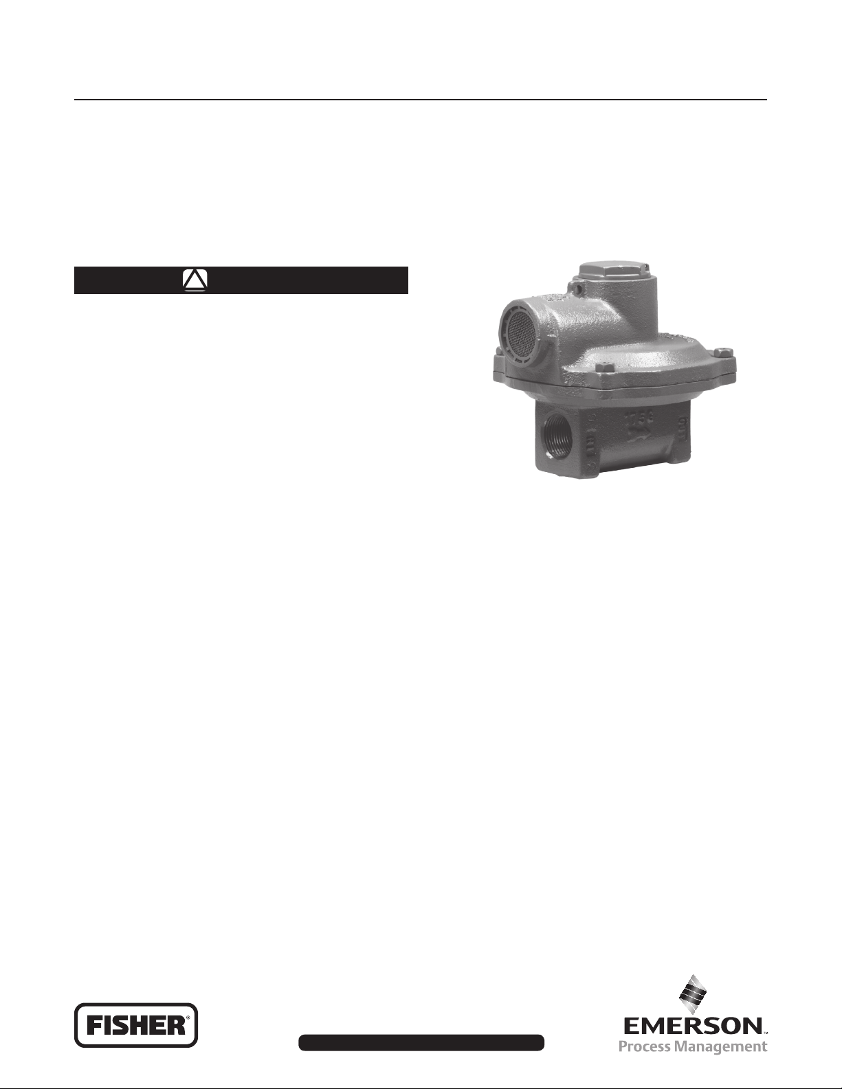
Type S402Y Pressure Reducing Regulator
WARNING
!
Failure to follow these instructions or
to properly install and maintain this
equipment could result in an explosion,
re and/or chemical contamination
causing property damage and personal
injury or death.
Fisher® regulators must be installed,
operated, and maintained in accordance
with federal, state, and local codes,
rules and regulations, and
manufacturer’s instructions.
If the regulator vents gas or a leak
develops in the system, service to
the unit may be required. Failure
to correct trouble could result in a
hazardous condition.
Call a gas service person to service
the unit. Only a qualied person must
install or service the regulator.
Introduction
This installation manual covers the installation and
startup procedures for Type S402Y pressure
reducing regulators.
Figure 1. Type S402Y Pressure Reducing Regulator Assembly
Scope of the Manual
This instruction manual provides information on
installation, maintenance, and replacement parts for
Type S402Y pressure-reduction regulators.
Product Description
The Type S402Y is generally employed in residential
or small commercial applications in order to reduce
gas distribution pressures to a specied pressure
range from 4.5-inches w.c. to 2.5 psig (11,0 mbar to
0,17 bar). The Type S402Y has an integral high
capacity internal relief valve.
The Type S402Y is typically used in residential
or small commercial applications to reduce gas
distribution pressures down to a reduced pressure
range from 4.5-inches w.c. to 2.5 psig (11,0 mbar
to 0,17 bar). The Type S402Y has an integral high
capacity internal relief valve.
www.emersonprocess.com/regulators
Specications
Specications for Type S402Y construction are found
on page 2. The following information is stamped on
the regulator at the factory: Type number, orice size,
spring range, and date of manufacture.
D101838X012
Page 2
Type S402Y
Specications
Body Size and End Connection Styles
(1)
NPS 3/4 or 1, NPT
Maximum Operating Inlet Pressure
(2)
125 psig (8,6 bar)
Maximum Allowable Emergency Inlet Pressure
175 psig (12,1 bar)
Allowable Outlet Pressures (Casing)
(2)
Emergency: 10 psig (0,69 bar)
Maximum Operating to Avoid Internal Part
Damage: 5 psig (0,35 bar)
Outlet Pressure Ranges
(2)
See Table 2
Orice Sizes
Temperature Capabilities
-20° to 160°F (-29° to 71°C)
Pressure Registration
Internal
(2)
Spring Case Vent Connection
1 NPT with removable screen (standard)
3/4 NPT with removable screen (optional)
Spring Case Vent and Body Mounting Positions
See Figure 5
External Dimensions
See Figure 6
Approximate Weight
4 pounds (2 kg)
(2)
See Table 1
1. End connections threaded to other than ASME standards can usually be supplied.
2. The pressure/temperature limits in this Instruction Manual and any applicable standard or code limitation should not be exceeded.
Table 1. Orice Sizes and Cg Coecients
ORIFICE SIZE
Inches mm Psig bar
1/8
3/16
1/4
1. Maximum operating inlet pressure is 125 psig (8,6 bar) for all orice sizes. The optimum performance is based on 2-inches w.c (5 mbar) boost or 1-inch w.c. (2 mbar) droop.
3,2
4,8
6,4
ORIFICE
COLOR CODE
Blue
Green
Brown
WIDE-OPEN C
RELIEF SIZING
12.5
28.2
50.0
FOR
g
MAXIMUM OPERATING PRESSURE FOR
OPTIMUM PERFORMANCE
125
80
60
(1)
8,6
5,5
4,1
Table 2. Outlet Pressure Ranges and Control Spring Data
OUTLET PRESSURE RANGES
4.5 to 6-inches w.c. (11 to 15 mbar) T13539T0012 Red 0.070 (1,78) 2.50 (63,5)
5.5 to 8-inches w.c. (14 to 20 mbar) T13527T0012 Yellow 0.067 (1,70) 2.59 (65,8)
7.5 to 9.5-inches w.c. (19 to 24 mbar) T13563T0012 Olive drab 0.067 (1,70) 3.24 (82,3)
9.5 to 13-inches w.c. (24 to 32 mbar) T13529T0012 Green 0.075 (1,91) 3.00 (76,2)
13-inches w.c. to 1.5 psig (32 mbar to 0,10 bar) T13564T0012 Unpainted 0.120 (3,05) 1.93 (49,0)
1.5 to 2.5 psig (0,10 to 0,17 bar) T13536T0012 Blue 0.120 (3,05) 2.60 (66,0)
Part Number Color Wire Diameter, Inches (mm) Free length, Inches (mm)
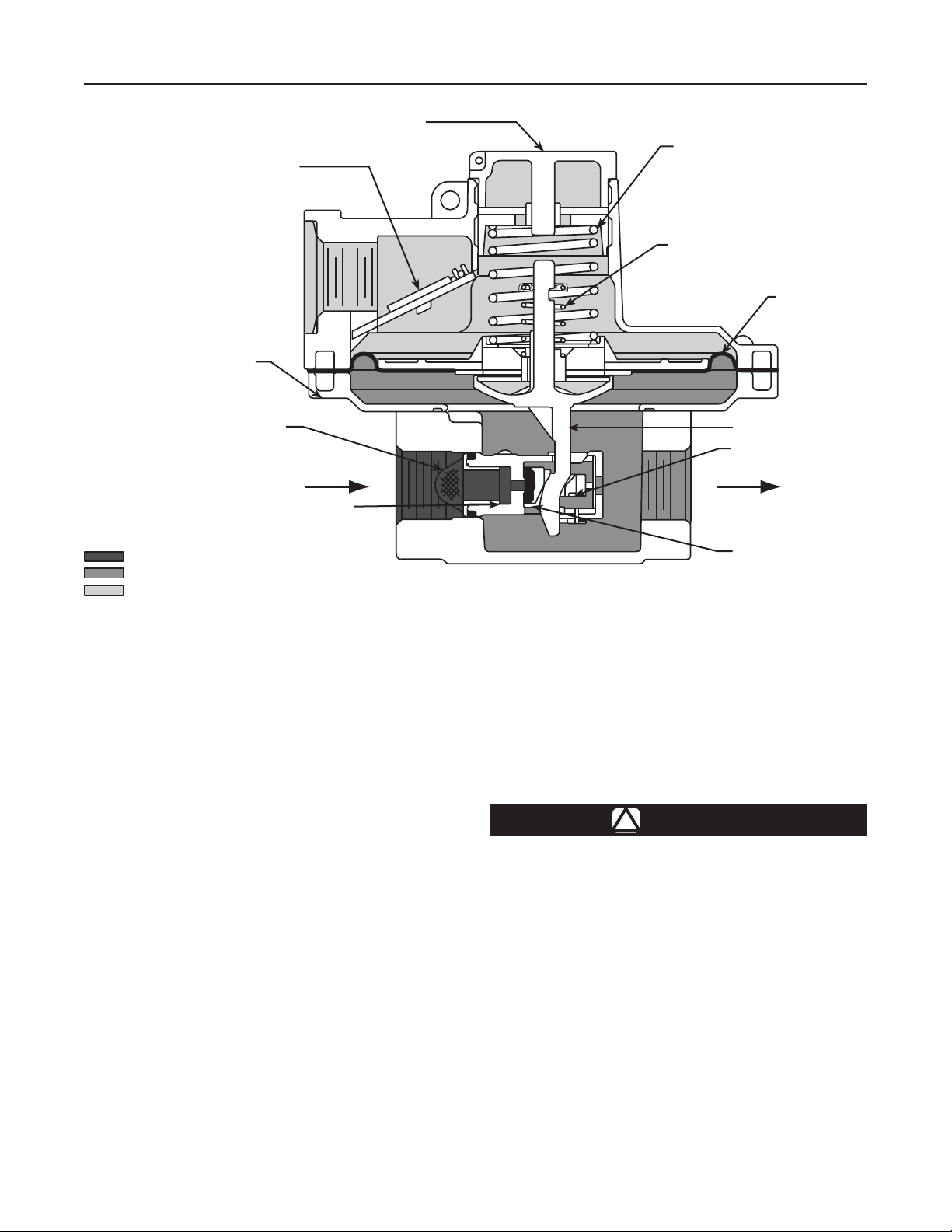
Principle of Operation
CONTROL SPRING DATA
assembly. When downstream demand is reduced, the
pressure under the diaphragm increases. This pressure
Inlet pressure ows through the open orice around
the valve disk and disk holder, around the cam stem
down the remaining length of the orice tube and into
the outlet of the regulator body. However, not all of the
pressure passes directly from the inlet to the outlet of
overcomes the regulator setting (which is set by a
spring) and moves the diaphragm assembly upwards.
This upward motion is transferred to the cam stem which
in turn bears against the sliding contact point on the
back side of the disk holder.
the regulator. Pressure is channelled through openings
in the orice tube and pressurizes the cavity formed by
the body and diaphragm/diaphragm head/cam stem
The inclined surface of the cam then forces the disk
holder toward the orice and reduces gas ow. If a higher
2
Page 3
INLET PRESSURE
OUTLET PRESSURE
ATMOSPHERIC PRESSURE
DRILLED CLOSING CAP WITH TRAVEL STOP
TO OPEN RELIEF VALVE
FLAPPER
LOWER CASING
Type S402Y
MAIN SPRING
RELIEF VALVE SPRING
DIAPHRAGM
INLET SCREEN
ORIFICE TUBE ASSEMBLY
M1162
INLET PRESSURE
OUTLET PRESSURE
ATMOSPHERIC PRESSURE
Figure 2. Type S402Y Operational Schematic
volume ow rate is demanded downstream, the pressure
under the diaphragm decreases. The control spring
force pushes the diaphragm/diaphragm head/cam stem
assembly downward and the valve disk moves away
from the orice.
At the lockup (complete shutoff) position the ratio of
the diaphragm travel to disk travel is 4 to 1 giving the
regulator an effective 4 to 1 lever ratio for positive lockup.
The cam stem is characterized for higher downstream
demand to produce a mechanical boost effect.
Type S402Y regulator includes an internal relief valve
for overpressure protection. If the downstream pressure
exceeds the regulator setting and the regulator is not
able to achieve complete shutoff (lockup) due to foreign
matter lodged between the orice and the valve disk
or a failure in the valve disk, the regulator diaphragm
assembly moves upwards trying to push the valve
disk against the orice. The valve disk and disk holder
being pressed against the orice will prevent the cam
stem from being able to travel any further upward in
conjunction with the diaphragm assembly. The continued
leakage of the inlet pressure into the regulator cavity
will then force the diaphragm and diaphragm head up
off of the seating area of the relief valve overcoming
CAM STEM
DISK HOLDER ASSEMBLY
VALVE DISK
the relief valve spring which was pressing them
together. The resulting gap will allow pressure to exit the
regulator cavity and exhaust through the openings in the
diaphragm head and out the spring case vent
to atmosphere.
Installation
WARNING
!
Personal injury, equipment damage, or
leakage due to escaping accumulated
gas or bursting of pressure-containing
parts may result if this regulator is
overpressured or is installed where
service conditions could exceed the
limits given in Specication Section.
To avoid such injury or damage, provide
pressure-relieving or pressure-limiting
devices (as required by Title 49, Part 192,
of the U.S. Code of Federal Regulations,
by the National Fuel Gas Code Title 54 of
the National Fire Codes of the National
Fire Protection Association, or by other
3
Page 4

Type S402Y
applicable codes) to prevent service
conditions from exceeding those limits.
Additionally, physical damage to the
regulator could result in personal
injury or property damage due to
escaping gas.
To avoid such injury and damage, install
the regulator in a safe location.
1. Only personnel qualied through training and
experience should install, operate, and maintain a
regulator. Before installing a Type S402Y
regulator, check for damage which have might
ocurred in shipment. Also check for dirt or foreign
materials which may have accumulated in the
regulator body or in the pipeline.
2. The Type S402Y may be installed in any position
(vertical or horizontal). Apply a good grade of
pipe compound to the male threads (being
sure not to apply pipe compound to ow path
of the pipe) of the pipe and install the regulator
so the ows is in the direction of the arrow cast
on the body. Use approved piping procedures
when installing the regulator. The spring case can
be rotated to any position relative to the body.
require additional vent protection from the
elements. Such protection may be with separate
hood, shields, or the Fisher
4. Regulator operation within the ratings does not
preclude the possibility of damage from the debris
in the lines or from external sources. A regulator
should be inspected for damage periodically and
after any overpressure condition.
5. With proper installation completed, slowly open
the upstream and downstream shutoff valves.
Check all connections for leaks. Check the
downstream equipment for proper operation.
6. If outlet pressure adjustment is necessary, monitor
downstream pressure with a gauge during the
adjustment procedure. To increase the outlet
pressure, the adjusting screw (key 12, Figure 1)
must be turned clockwise. This requires removal of
the closing cap (key 11, Figure 1). To reduce the
outlet pressure setting, turn the adjusting screw
counter-clockwise. Do not adjust the spring to
procedure an outlet pressure setting above the limit
stamped on the regulator.
®
Y602 Series vents.
Overpressure Protection
WARNING
!
A regulator may vent some gas to
the atmosphere. In hazardous or
ammable gas service, vented gas
may accumulate, and cause personal
injury, death, or property damage due
to re or explosion. Vent a regulator
in hazardous gas service to a remote,
safe location away from air intakes or
any hazardous location. The vent line
or stack opening must be protected
against condensation or clogging.
Under enclosed conditions or indoors,
escaping gas may accumulate and be
an explosion hazard. In these cases,
the Type S402Y vent should be piped
away from the regulator to a safe
location outdoors.
3. On outdoors installations, regulators installed with
vents in positions other than vertically down
The wide-open Cg for relief sizing along with the
capacity information should be used in choosing
appropriate overpressure protection devices to
ensure that none of the limits in the Specications
section, Table 1, or Table 2 are exceeded.
Overpressuring any portion of a regulator or
associated equipment may cause leakage,
parts damage, or personal injury due to bursting
of pressure-containing parts or explosion of
accumulated gas. Regulator operation within ratings
does not prevent the possibility of damage from
external sources or from debris in the pipeline. A
regulator should be inspected for damage after any
overpressure condition.
Startup
WARNING
!
In order to avoid an overpressure
condition and possible equipment
damage, pressure gauges should
always be used to monitor pressures
during startup.
4
Page 5

Type S402Y
1. Check to see that all downstream equipment is
turned off.
2. Slowly open the upstream shutoff valve.
3. Slowly open the downstream shutoff valve.
4. Check all connections for leaks.
5. Light the downstream equipment pilot lights
if applicable.
Adjustment
If set pressure adjustment is necessary, monitor
downstream pressure with a gauge during the
adjustment procedure. To increase the outlet
pressure, the adjusting screw (key 12) must be turned
clockwise. This requires removal of the closing cap
(key 11). To reduce the outlet pressure setting, turn
the adjusting screw counterclockwise. Do not adjust
the spring to produce an outlet pressure setting above
the limit stamped on the regulator.
The range of allowable pressure settings is stamped
on the regulator. If a pressure setting beyond this
range is necessary, substitute the appropriate
regulator control spring. When changing the spring,
also change the range stamped on the regulator to
indicate the actual pressure range of the spring in use.
Before increasing the setting, refer to Table 1. Review
the pressure limits for the control spring range being
used and be certain that the new pressure setting
will not result in an overpressure condition. After the
spring adjustment has been completed, replace the
closing cap.
Maintenance
WARNING
!
To avoid personal injury or equipment
damage from sudden release of pressure
or uncontrolled gas, do not attempt any
maintenance or disassembly without
rst isolating the regulator from
system pressure and relieving all
internal pressure as described in the
shutdown procedure.
Regulators that have been diassembled
for repair must be tested for proper
operation before being returned to
service. Due to the care Fisher takes in
meeting all manufacturing requirements
(heat treating, dimensional tolerances,
etc.), use only replacement parts
manufactured or furnished by Fisher to
repair Fisher® regulators. Relight
pilot lights according to normal
startup procedures.
Due to normal wear or damage that
may occur from external sources, this
regulator should be inspected and
maintained periodically. The frequency
of inspection and replacement of parts
depends upon the severity of service
conditions or the requirements of local,
state, and federal rules and regulations.
A program of periodic regulator inspection should be
established. Visually inspect the regulator for:
Shutdown
Installation arrangements may vary, but in any
installation it is important that the shutoff valves be
opened or closed slowly and that the outlet pressure
be vented before venting inlet pressure to prevent
damage caused by reverse pressurization of the
regulator. The steps below apply to the typical
installation as indicated.
1. Slowly close the upstream shutoff valve.
2. Release downstream pressure and be sure the
upstream pressure has been exhausted.
1. Improper installation.
2. Plugged or frozen vent.
3. Wrong regulator in the system.
4. Internal or external corrosion.
5. Age of the regulator.
6. Any other condition that could cause the
uncontrolled escape of gas.
Failure to establish an inspection program, as
outlined above, could result in personal injury or
property damage.
5
Page 6

Type S402Y
Make sure the regulator vent, vent assembly, or vent
pipe does not become plugged by mud, insects, ice,
snow, paint, or etc. The vent screen aids in keeping
the vent from becoming plugged, and the screen
should be clean and properly installed.
Replace any regulators that have had water in their
spring case and/or show evidence of external or
internal corrosion. Checking for internal corrosion may
require complete removal of the adjusting screw and
shutdown of the gas system.
Older regulators are more likely to fail because
of worn, damaged or corroded parts. Periodic
repair of the diaphragm assembly, orice tube
assembly, and other parts subject to wear and/
or corrosion; or a systematic replacement program
should be based on the regulator’s performance,
the service area’s environment, installation practices,
and historical experience.
The following procedures are for complete regulator
disassembly and assembly. All pressure must be
released from the regulator before the following steps
can be performed. While using the maintenance
procedures, refer to Figure 3 for key number locations.
Note
The regulator may remain in the pipeline
during maintenance procedures unless
the body (key 1) is replaced or removed
for repairs.
5. Reassemble in the reverse order of the above
procedures. Place the diaphragm assembly into
position in the lower casing, being sure the
cam stem (key 10) is properly inserted into the
orice tube assembly (key 7). Note that the
diaphragm plate is marked with “Inlet” and
“Outlet”. Install the spring case assembly (key 3)
and using a crisscross pattern, tighten the spring
case screws (key 13).
Orice Tube Assembly Replacement
1. Remove the spring case screws (key 13) which
hold the lower casing to the body (key 1).
Note
When the actuator assembly is
separated from the body, do not rotate
the diaphragm/relief valve assembly
without removing the spring case
screws (key 13). The assembly
incorporates an anti-rotation design,
any rotational movement will damage
the cam stem/diaphragm assembly.
2. Remove the diaphragm/relief valve assembly
(key 10) by tilting it toward the outlet so that the
cam stem slides up and out of the orice tube
assembly (key 7).
3. Remove the orice tube screws (key 9) and then
the orice tube assembly (key 7).
Control Spring or Diaphragm
Assembly Replacement
1. Remove the closing cap (key 11) and turn the
adjusting screw (key 12) counterclockwise until
all compression is removed from the control
spring (key 6).
2. If changing the control spring (key 6) is the only
maintenance required, remove and replace the
control spring.
3. To replace or reposition the spring case, remove
the spring case screws (key 13) and lift off the
spring case assembly (key 3).
4. For diaphragm maintenance, remove the
diaphragm assembly by tilting it toward
the outlet so that the cam stem may be
pulled up and out of the orice tube
assembly (key 7).
4. Reassemble in the reverse order of the above
procedure. Be sure to use a new orice tube
O-ring (key 8), body with O-ring lubricant.
5. Tighten the spring case screws (key 13) to
80-inch-pounds (9.0 N•m) of torque.
6. If necessary, refer to the installation and/or the
startup and adjustment procedures.
Parts Ordering
When corresponding with your local Sales Ofce about
this equipment, always reference the Type number that
can be found stamped on the regulator.
When ordering replacement parts, reference the key
number of each needed part as found in the following
parts list. Separate kits containing all recommended
spare parts are available. If construction changes
are made in the eld, be sure that the information
on the regulator is also changed to reect the most
recent construction.
6
Page 7

Type S402Y
3
11
12 6
10
9
1
22
- Apply Lub / Sealant
4
5
16
8
7
13
T80288
Figure 3. Type S402Y Pressure Reducing Regulator Assembly
7
Page 8

Type S402Y
Parts List
Key Description Part Number
1 Body, Cast Iron
No Gauge Tap
NPS 3/4, NPT T80281T0012
NPS 1, NPT T80282T0012
Outlet Gauge Tap
NPS 3/4, NPT T13649T0012
NPS 1, NPT T13649T0022
3 Spring Case Assembly
For 1 NPT vent T20932T0012
For 3/4 NPT vent T20932T0032
4 Screen-Vent, 18-8 Stainless Steel T1121338982
5 Retaining Ring, Zinc-plated Steel T1120925072
6 Control spring
4.5 to 6-inches w.c. (11 to 15 mbar), 302 SST T13539T0012
5.5 to 8-inches w.c. (14 to 20 mbar),
Zinc-plated steel T13527T0012
7.5 to 9.5-inches w.c. (19 to 24 mbar),
Zinc-plated steel T13563T0012
9.5 to 13-inches w.c. (24 to 32 mbar),
Zinc-plated steel T13529T0012
13-inches w.c. to 1.5 psig (0,03 to 0,10 bar),
302 SST T13564T0012
1.5 to 2.5 psig (0,10 to 0,17 bar), Steel T13536T0012
Key Description Part Number
7 Orice Tube Assembly T13651T0012
1/8-inch T13651T0012
3/16-inch T13651T0112
1/4-inch T13651T0032
8* Orice Tube, O-Ring, Nitrile (NBR) 18B3438X012
9 Orice Tube Screw, Steel T13526T0012
10 Diaphragm/Relief Valve Assembly
Relief Valve Spring Color
Blue T20930T0012
Orange T20930T0022
Green T20930T0032
Red T20930T0042
Brown T20930T0052
11 Closing Cap, ASA 309, Gray T13524T0062
12 Adjusting Screw
4.5 to 6-inches w.c. (11 to 15 mbar), Delrin
5.5 to 8-inches w.c. (14 to 20 mbar), Delrin T13523T0012
7.5 to 9.5-inches w.c. (19 to 24 mbar), Delrin T13523T0012
9.5 to 13-inches w.c. (24 to 32 mbar), Delrin T13523T0012
13-inches w.c. to 1.5 psig (32 mbar to 0,10 bar),
Zinc 1B537944012
1.5 to 2.5 psig (0,10 to 0,17 bar), Zinc 1B537944012
13 Machiine Screw, Steel (4 required) T13646T0012
16 Pipe Plug, 304 Stainless Steel 1E823135042
22 Screen, 18-8 Stainless steel
For 3/4 NPT vent T13643T0012
For 1 NPT vent T13644T0012
23* Gasket, Neoprene (CR) (not shown) 1P753306992
®
T13523T0012
*Recommended spare part.
Delrin® is a mark owned by E. I. du Pont de Nemours and Co.
Industrial Regulators
Emerson Process Management
Regulator Technologies, Inc.
USA - Headquarters
McKinney, Texas 75069-1872 USA
Tel: 1-800-558-5853
Outside U.S. 1-972-548-3574
Asia-Pacic
Shanghai, China 201206
Tel: +86 21 2892 9000
Europe
Bologna, Italy 40013
Tel: +39 051 4190611
Middle East and Africa
Dubai, United Arab Emirates
Tel: +971 4811 8100
For further information visit www.emersonprocess.com/regulators
The Emerson logo is a trademark and service mark of Emerson Electric Co. All other marks are the property of their prospective owners. Fisher is a mark owned by Fisher Controls, Inc., a
business of Emerson Process Management.
The contents of this publication are presented for informational purposes only, and while every eort has been made to ensure their accuracy, they are not to be construed as warranties or
guarantees, express or implied, regarding the products or services described herein or their use or applicability. We reserve the right to modify or improve the designs or specications of such
products at any time without notice.
Emerson Process Management does not assume responsibility for the selection, use or maintenance of any product. Responsibility for proper selection, use and maintenance of any Emerson
Process Management product remains solely with the purchaser.
Natural Gas Technologies
Emerson Process Management
Regulator Technologies, Inc.
USA - Headquarters
McKinney, Texas 75069-1872 USA
Tel: 1-800-558-5853
Outside U.S. 1-972-548-3574
Asia-Pacic
Singapore, Singapore 128461
Tel: +65 6777 8211
Europe
Bologna, Italy 40013
Tel: +39 051 4190611
Gallardon, France 28320
Tel: +33 (0)2 37 33 47 00
TESCOM
Emerson Process Management
Tescom Corporation
USA - Headquarters
Elk River, Minnesota 55330-2445 USA
Tel: 1-763-241-3238
Europe
Selmsdorf, Germany 23923
Tel: +49 (0) 38823 31 0
©Emerson Process Management Regulator Technologies, Inc., 1992, 2009; All Rights Reserved
 Loading...