

Page 1
User Manual
GFK-2224Y
August 2019
PACSystems™ RX3i and RSTi-EP TCP/IP
Ethernet Communications User Manual
Page 2

Warnings and Caution Notes as Used in this Publication
WARNING
Warning notices are used in this publication to emphasize that hazardous voltages, currents,
temperatures, or other conditions that could cause personal injury exist in this equipment or may be
associated with its use.
In situations where inattention could cause either personal injury or damage to equipment, a Warning
notice is used.
CAUTION
Caution notices are used where equipment might be damaged if care is not taken.
Note: Notes merely call attention to information that is especially significant to understanding and operating the
equipment.
These instructions do not purport to cover all details or variations in equipment, nor to provide for every
possible contingency to be met during installation, operation, and maintenance. The information is
supplied for informational purposes only, and Emerson makes no warranty as to the accuracy of the
information included herein. Changes, modifications, and/or improvements to equipment and
specifications are made periodically and these changes may or may not be reflected herein. It is
understood that Emerson may make changes, modifications, or improvements to the equipment
referenced herein or to the document itself at any time. This document is intended for trained personnel
familiar with the Emerson products referenced herein.
Emerson may have patents or pending patent applications covering subject matter in this document. The
furnishing of this document does not provide any license whatsoever to any of these patents.
Emerson provides the following document and the information included therein as-is and without
warranty of any kind, expressed or implied, including but not limited to any implied statutory warranty of
merchantability or fitness for particular purpose.
© 2019 Emerson. All rights reserved.
Emerson Terms and Conditions of Sale are available upon request. The Emerson logo is a
trademark and service mark of Emerson Electric Co. All other marks are the property of their
respective owners.
Page 3

Contents i
Table of Contents
Table of Contents ..................................................................................................................................... i
Table of Figures ....................................................................................................................................... ix
Section 1: Introduction......................................................................................................................... 1
1.1 Revisions in this Manual ........................................................................................................ 2
1.2 PACSystems Documentation ................................................................................................ 3
1.2.1 PACSystems Manuals ................................................................................................... 3
1.2.2 RX3i Manuals ............................................................................................................... 3
1.2.3 RSTi-EP Manuals ........................................................................................................... 4
1.3 Ethernet Interfaces for PACSystems Controllers ..................................................................... 5
1.3.1 RX3i Rack-Based Ethernet Interfaces – Features ........................................................... 5
1.3.2 RX3i & RSTi-EP Embedded Ethernet Interface - Features ............................................... 6
1.3.3 Ethernet Interface Specifications .................................................................................. 8
1.3.4 Ethernet interface Ports ............................................................................................. 10
1.3.5 Station Manager ......................................................................................................... 11
1.3.6 Firmware Upgrades .................................................................................................... 12
1.3.7 SRTP Client (Channels) ............................................................................................... 12
1.3.8 Modbus TCP Client (Channels) ................................................................................... 12
1.3.9 Ethernet Global Data (EGD) ........................................................................................ 13
1.3.10 SRTP Inactivity Timeout .............................................................................................. 14
1.4 Ethernet Redundancy Operation ......................................................................................... 14
1.4.1 Hot Standby (HSB) CPU Redundancy .......................................................................... 15
1.4.2 Non-HSB Redundancy ................................................................................................ 16
1.4.3 Effect of Redundancy Role Switching on Ethernet Communications ........................... 16
1.4.4 SRTP Server Operation in a Redundancy System ......................................................... 18
1.4.5 SRTP Client Operation in a Redundancy System .......................................................... 18
1.4.6 Modbus TCP Server Operation in a Redundancy System ............................................. 19
1.4.7 Modbus TCP Client Operation in a Redundancy System .............................................. 19
1.4.8 EGD Class 1 (Production & Consumption) in a Redundancy System ............................ 19
1.4.9 EGD Class 2 Commands in a Redundancy System ....................................................... 19
1.4.10 Web Server Operation in a Redundancy System ......................................................... 20
1.4.11 FTP Operation in a Redundancy System ...................................................................... 20
1.4.12 SNTP Operation in a Redundancy System ................................................................... 20
1.4.13 Remote Station Manager Operation in a Redundancy System..................................... 20
1.4.14 IP Address Configuration in a Redundancy System ...................................................... 21
Page 4

Contents ii
Section 2: Installation and Start-up: RX3i/RSTi-EP Embedded Interface .................................................. 22
2.1 RX3i/RSTi-EP Embedded Ethernet Interface Indicators .......................................................... 22
2.1.1 Ethernet Port LEDs Operation ..................................................................................... 22
2.1.2 Module Installation .................................................................................................... 25
2.2 Ethernet Port Connector ..................................................................................................... 25
2.2.1 Connection to a 10Base-T/100Base-TX Network......................................................... 25
2.2.2 10Base-T/100Base-TX Port Pinouts ............................................................................ 25
2.3 Pinging TCP/IP Ethernet interfaces on the Network ............................................................... 26
2.3.1 Determining if an IP Address is Already Being Used ..................................................... 26
Section 3: Installation and Start-up: Ethernet Module Interfaces ........................................................... 27
3.1 Ethernet Module Interface Characteristics............................................................................ 28
3.1.1 Front Panel Port ......................................................................................................... 29
3.1.2 Ethernet Port Connections ......................................................................................... 29
3.1.3 LEDs on the RX3i Ethernet Interface Module ............................................................... 30
3.1.4 Ethernet LEDs ............................................................................................................. 30
3.1.5 Restart/Reset Pushbutton Operation .......................................................................... 32
3.2 Ethernet Module Installation ............................................................................................... 34
3.2.1 Module Installation .................................................................................................... 34
3.2.2 Module Removal ........................................................................................................ 34
3.3 Ethernet Port Connectors ................................................................................................... 35
3.3.1 Embedded Switch ...................................................................................................... 35
3.3.2 Connection to a 10Base-T/100Base-TX/1000Base-T Network ..................................... 37
3.4 Station Manager Port .......................................................................................................... 39
3.4.1 Port Settings .............................................................................................................. 39
3.5 Verifying Proper Power-Up of the Ethernet Interface After Configuration ............................... 39
3.6 Pinging TCP/IP Ethernet interfaces on the Network ............................................................... 40
3.6.1 Determining if an IP Address is Already Being Use ....................................................... 40
3.7 Ethernet Plug-in Applications .............................................................................................. 41
Section 4: Configuration ..................................................................................................................... 42
4.1 RX3i/RSTi-EP Embedded Ethernet Interfaces ........................................................................ 43
4.1.1 Ethernet Configuration Data ...................................................................................... 43
4.1.2 Initial IP Address Assignment ...................................................................................... 44
Page 5

Contents iii
4.1.3 Configuring the Ethernet Interface Parameters .......................................................... 45
4.2 RX3i Rack-Based Ethernet Interface Modules........................................................................ 57
4.2.1 Ethernet Configuration Data ...................................................................................... 58
4.2.2 Initial IP Address Assignment ...................................................................................... 59
4.2.3 Configuring Ethernet Interface Parameters ................................................................ 64
4.2.4 Configuring Ethernet Global Data ............................................................................... 71
Section 5: Ethernet Global Data .......................................................................................................... 90
5.1 Comparison Model for Ethernet Global Data Support ........................................................... 91
5.2 Ethernet Global Data Operation .......................................................................................... 91
5.2.1 EGD Producer ............................................................................................................. 91
5.2.2 EGD Consumers ......................................................................................................... 92
5.3 EGD Exchanges .................................................................................................................. 92
5.3.1 Content of an Ethernet Global Data Exchange ............................................................ 93
5.3.2 Data Ranges (Variables) in an Ethernet Global Data Exchange .................................... 93
5.3.3 Valid Memory Types for Ethernet Global Data............................................................. 93
5.3.4 Planning Exchanges .................................................................................................... 95
5.3.5 Using Ethernet Global Data in a Redundancy System .................................................. 95
5.4 Sending an Ethernet Global Data Exchange to Multiple Consumers ....................................... 95
5.4.1 Multicasting Ethernet Global Data .............................................................................. 96
5.4.2 Broadcasting Ethernet Global Data ............................................................................. 97
5.4.3 Changing Group ID in Run Mode ................................................................................ 97
5.5 Ethernet Global Data Timing ............................................................................................... 99
5.5.1 EGD Synchronization .................................................................................................. 99
5.5.2 Configurable Producer Period for an EGD Exchange .................................................. 100
5.5.3 Consumer Update Timeout Period ........................................................................... 100
5.6 Effect of PLC Modes and Actions on EGD Operations ........................................................... 102
5.6.1 Run Mode Store of EGD ............................................................................................ 103
5.7 Monitoring Ethernet Global Data Exchange Status .............................................................. 108
5.7.2 Exchange Status Word Error Codes ........................................................................... 108
Page 6

Contents iv
Section 6: Programming EGD Commands ......................................................................................... 110
6.1 General Use of EGD Commands......................................................................................... 111
6.2 Using EGD Commands in a Redundancy System ................................................................. 111
6.3 COMMREQ Format for Programming EGD Commands ........................................................ 111
6.4 COMMREQ Status for the EGD Commands ......................................................................... 112
6.4.1 COMMREQ Status Values ......................................................................................... 113
6.5 Read PLC Memory (4000).................................................................................................. 113
6.5.1 Read PLC Memory Command Block .......................................................................... 114
6.6 Write PLC Memory (4001) ................................................................................................. 117
6.6.1 Write PLC Memory Command Block ......................................................................... 117
6.7 Read EGD Exchange (4002) ............................................................................................... 119
6.7.1 Read EGD Exchange Command Block ....................................................................... 119
6.8 Write EGD Exchange (4003) .............................................................................................. 122
6.8.1 Write EGD Exchange Command Block ...................................................................... 122
6.9 Masked Write to EGD Exchange (4004) .............................................................................. 124
6.9.1 Masked Write EGD Exchange Command Block ......................................................... 124
Section 7: SNTP Operation................................................................................................................ 127
7.1 Normal SNTP Operation .................................................................................................... 127
7.1.1 SNTP Broadcast and Multicast Operation Mode ........................................................ 127
7.1.2 SNTP Unicast Operation Mode.................................................................................. 127
7.2 Multiple SNTP Servers (Applies only to SNTP Broadcast and Multicast Mode) ........................ 128
7.3 Loss or Absence of SNTP Timing Signals ............................................................................. 128
7.4 Time-Stamping of Ethernet Global Data Exchanges ............................................................ 129
7.4.1 Obtaining Timestamps from the Ethernet Interface Clock ........................................ 130
7.4.2 Obtaining Timestamps from the CPU TOD Clock ...................................................... 132
Section 8: Programming SRTP Channel Commands ........................................................................... 143
8.1 Model Comparison for SRTP Server Capabilities .................................................................. 144
8.2 SRTP Channel Commands ................................................................................................. 144
8.2.1 Channel Operations ................................................................................................. 144
8.2.2 Aborting and Re-tasking a Channel ........................................................................... 145
Page 7

Contents v
8.2.3 Monitoring the Channel Status ................................................................................. 145
8.2.4 SRTP Channel Commands in a Redundant System .................................................... 145
8.2.5 Executing a Channel Command ................................................................................ 146
8.3 COMMREQ Format for Programming Channel Commands .................................................. 147
8.3.1 The COMMREQ Command Block: General Description ............................................. 148
8.3.2 Establish Read Channel (2003) ................................................................................. 150
8.3.3 Establish Write Channel (2004) ................................................................................ 154
8.3.4 Send Information Report (2010) ............................................................................... 157
8.3.5 Abort Channel (2001) ............................................................................................... 160
8.3.6 Retrieve Detailed Channel Status (2002) .................................................................. 161
8.4 Programming for Channel Commands ............................................................................... 164
8.4.1 COMMREQ Sample Logic .......................................................................................... 164
8.4.2 Sequencing Communications Requests .................................................................... 167
8.4.3 Managing Channels and TCP Connections ................................................................ 168
8.4.4 Use “Channel Re-Tasking” To Avoid Using Up TCP Connections ................................ 168
8.4.5 Client Channels TCP Resource Management ............................................................. 169
8.4.6 SRTP Application Timeouts....................................................................................... 169
8.5 Monitoring Channel Status ............................................................................................... 170
8.5.1 Format of the COMMREQ Status Word ..................................................................... 170
Section 9: Modbus/TCP Server .......................................................................................................... 172
9.1 Model Comparison for Modbus/TCP Server Capabilities ...................................................... 173
9.2 Modbus Conformance Classes ........................................................................................... 174
9.2.1 Server Protocol Services ........................................................................................... 174
9.2.2 Station Manager Support ......................................................................................... 174
9.3 Reference Mapping .......................................................................................................... 174
9.3.1 Modbus Reference Tables ........................................................................................ 174
9.3.2 Address Configuration ............................................................................................. 176
9.4 Modbus Function Codes ................................................................................................... 177
Section 10: Modbus/TCP Client .............................................................................................. 179
10.1 Model Comparison for Modbus/TCP Client Capabilities ....................................................... 180
10.2 Communications Request ................................................................................................. 180
10.2.1 Structure of the Communications Request ............................................................... 180
10.2.2 COMMREQ Function Block ....................................................................................... 181
10.2.3 COMMREQ Command Block ..................................................................................... 181
Page 8

Contents vi
10.2.4 Modbus/TCP Channel Commands ............................................................................ 181
10.2.5 Status Data .............................................................................................................. 182
10.2.6 Operation of the Communications Request .............................................................. 182
10.3 COMMREQ Function Block and Command Block ................................................................ 184
10.3.1 The COMMREQ Function Block ................................................................................. 184
10.3.2 The COMMREQ Command Block .............................................................................. 185
10.4 Modbus/TCP Channel Commands ..................................................................................... 186
10.4.1 Open a Modbus/TCP Client Connection (3000) ......................................................... 186
10.4.2 Close a Modbus/TCP Client Connection (3001) ......................................................... 189
10.4.3 Read Data from a Modbus/TCP Device (3003) .......................................................... 190
10.4.4 Write Data to a Modbus/TCP Device (3004) .............................................................. 197
10.4.5 Mask Write Register Request to a Modbus Server Device (3009) ............................... 201
10.4.6 Read/Write Multiple Registers to/from a Modbus Server Device (3005) .................... 202
10.5 Status Data ...................................................................................................................... 204
10.5.1 Types of Status Data ................................................................................................. 204
10.6 Controlling Communications in the Ladder Program .......................................................... 205
10.6.1 Essential Elements of the Ladder Program ................................................................ 205
10.6.2 Managing Channels and TCP Connections ................................................................ 206
10.6.3 Client Channels TCP Resource Management ............................................................. 206
10.6.4 COMMREQ Ladder Logic Example ............................................................................. 207
10.6.5 Troubleshooting a Ladder Program .......................................................................... 212
10.6.6 Monitoring the Communications Channel ................................................................ 213
Section 11: OPC UA Server ..................................................................................................... 217
11.1 Model Comparison for OPC UA Server Capabilities .............................................................. 218
11.2 OPC UA Certificate Security ............................................................................................... 218
11.2.1 Controlling the OPC UA Server with PAC Machine Edition ......................................... 218
11.2.2 Application Logic to Control the OPC UA Server ........................................................ 222
11.2.3 Connect OPC UA Client to OPC UA Server ................................................................. 232
Page 9

Contents vii
Section 12: Diagnostics ......................................................................................................... 245
12.1 What to do if You Cannot Solve the Problem ...................................................................... 246
12.2 Diagnostic Tools Available for Troubleshooting .................................................................. 246
12.3 Initialization Example of the RX3i Ethernet ETM001-Jx Module Interface .............................. 248
12.4 ETHERNET OK/OK LED Blink Codes for Hardware Failures (ETM001-Jx) ................................. 250
12.5 Controller Fault Table ....................................................................................................... 251
12.5.1 Controller Fault Table Descriptions ........................................................................... 252
12.6 Monitoring the Ethernet Interface Status Bits ..................................................................... 255
12.6.1 LAN Interface Status (LIS) Bits ................................................................................... 258
12.6.2 Channel Status Bits ................................................................................................... 260
12.7 Monitoring the FT Output of the COMMREQ Function Block. ............................................... 261
12.8 Monitoring the COMMREQ Status Word ............................................................................ 263
12.8.1 Format of the COMMREQ Status Word ..................................................................... 263
12.8.2 Major Error Codes in the COMMREQ Status Word ..................................................... 264
12.8.3 Minor Error Codes for Major Error Codes 05H (at Remote Server PLC) and 85H (at Client
PLC) ......................................................................................................................... 265
12.8.4 Minor Error Codes for Major Error Code 11H (at Remote Server PLC) ......................... 266
12.8.5 Minor Error Codes for Major Error Code 90H (at Client PLC) ...................................... 268
12.8.6 Minor Error Codes for Major Error Code 91H (at Remote Modbus/TCP Server) .......... 271
12.8.7 Minor Error Codes for Major Error Code A0H (at Client PLC) ...................................... 272
12.9 Using the EGD Management Tool (RX3i Ethernet Module) .................................................. 273
12.9.1 Installing the EGD Management Tool ....................................................................... 273
12.9.2 Launching the EGD Management Tool ..................................................................... 273
12.9.3 Monitoring EGD Devices ........................................................................................... 274
12.9.4 Monitoring Status of Ethernet Global Data for a Device ............................................ 275
12.10 Troubleshooting Common Ethernet Difficulties ................................................................. 279
12.10.1 COMMREQ Fault Errors ............................................................................................. 279
12.10.2 PLC Timeout Errors ................................................................................................... 279
12.10.3 Application Timeout Errors ....................................................................................... 281
12.10.4 EGD Configuration Mismatch Errors ......................................................................... 281
12.10.5 Station Manager Lockout under Heavy Load ............................................................. 282
12.10.6 PING Restrictions ..................................................................................................... 282
12.10.7 SRTP and Modbus/TCP Connection Timeout ............................................................ 282
12.10.8 Sluggish Programmer Response after Network Disruption ....................................... 283
Page 10

Contents viii
12.10.9 EGD Command Session Conflicts .............................................................................. 285
12.10.10 SRTP Request Incompatibility with Existing Host Communications Toolkit Devices or
Other SRTP Clients ................................................................................................... 285
12.10.11 COMMREQ Flooding Can Interrupt Normal Operation .............................................. 285
12.10.12 Accelerated EGD Consumption Can Interfere with EGD Production .......................... 285
12.10.13 Channels Operation Depends Upon PLC Input Scanning ........................................... 286
Section 13: Network Administration ....................................................................................... 288
13.1 IP Addressing ................................................................................................................... 288
13.1.1 IP Address Format for Network Classes A, B, C .......................................................... 288
13.1.2 IP Addresses Reserved for Private Networks .............................................................. 289
13.1.3 Multicast IP Addresses .............................................................................................. 289
13.1.4 Loopback IP Addresses ............................................................................................. 289
13.1.5 Overlapping Subnets ................................................................................................ 290
13.2 Gateways ......................................................................................................................... 293
13.2.1 Networks Connected by a Gateway .......................................................................... 293
13.3 Subnets and Supernets ..................................................................................................... 293
13.3.1 Subnet Addressing and Subnet Masks ...................................................................... 294
13.3.2 Example: Network Divided into Two Subnets ............................................................ 294
13.3.3 Example: Two Networks Combined into a Supernet .................................................. 295
SNTP Time Transfer to CPU Parameters (task n) .................................................................................... 303
Page 11

Contents ix
Table of Figures
Figure 1: Ethernet Connection System Diagram ..................................................................................................... 5
Figure 2: Ethernet Operation in Redundancy Mode .............................................................................................. 15
Figure 3: Basic Non-HSB System with Redundant IP.............................................................................................. 16
Figure 4: RJ45 Connector ..................................................................................................................................... 25
Figure 5: Ethernet Cable Routing ......................................................................................................................... 26
Figure 6: ETM001-Jx Faceplate ............................................................................................................................. 28
Figure 7: ETM001-Kxxx Faceplate ........................................................................................................................ 28
Figure 8: Ethernet Port Connectors on IC695ETM001-Kxxx ................................................................................... 29
Figure 9: Install Module into RX3i Backplane ........................................................................................................ 34
Figure 10: Remove Module from RX3i Backplane ................................................................................................. 34
Figure 11: Diagram of Embedded Ethernet Switch ............................................................................................... 35
Figure 12: System Diagram: Ethernet Routing Using Embedded Switch ................................................................ 36
Figure 13: Connection Using Hub/Switch/Repeater .............................................................................................. 38
Figure 14: Direct Connection to the Embedded Ethernet Ports .............................................................................. 38
Figure 15: Expand CPU Slot to Display Ethernet Node ........................................................................................... 44
Figure 16: Expand RX3i CPU Node to Configure Embedded Ethernet interface ....................................................... 47
Figure 17: CPE330/CPE400/CPL410/CPE100/CPE115/ETM001-Kxxx Settings tab .................................................. 49
Figure 18: CPE330 Advanced Ethernet Configuration LAN1 & LAN2 ...................................................................... 50
Figure 19: CPE100/CPE115/CPE400/CPL410 Advanced Ethernet Configuration LAN1 & LAN2 ............................... 51
Figure 20: SNTP PME configuration for the CPE302/CPE305/CPE310/CPE330/CPE400/CPL410 CPU settings .......... 52
Figure 21: SNTP Multicast/Broadcast or Unicast Mode Settings ............................................................................ 52
Figure 22: UTC Time Zone Settings ...................................................................................................................... 53
Figure 23: Terminals Tab Settings in PAC Machine Edition .................................................................................... 53
Figure 24: Adding Ethernet Global Data (EGD) to the Configuration ..................................................................... 54
Figure 25: Defining EGD Produced Data Exchange ............................................................................................... 55
Figure 26: Defining EGD Consumed Data Exchange ............................................................................................. 55
Figure 27: Configuring Multicast & Broadcast EGD on LAN1 ................................................................................. 56
Figure 28: Configuring Multicast & Broadcast EGD on LAN2 ................................................................................. 57
Figure 29: Setting Temporary IP Address .............................................................................................................. 60
Figure 30: Install ETM001-Jx Module in Rack/Slot & Expand to Configure .............................................................. 64
Figure 31: Expand Node to View Ethernet Global Data ......................................................................................... 71
Figure 32: Local Producer ID ................................................................................................................................ 72
Figure 33: Configuring the EGD Configuration Server ........................................................................................... 73
Figure 34: Exchange ID Offset in an Ethernet Redundancy System ........................................................................ 88
Figure 35: Configuring Redundancy for Ethernet Global Data ............................................................................... 89
Figure 36: Configuring Produce in Backup Mode Parameter ................................................................................. 89
Figure 37: Producing & Consuming Ethernet Global Data ..................................................................................... 91
Page 12

Contents x
Figure 38: Adding Symbolic Reference to Ethernet Global Data Exchange ............................................................. 94
Figure 39: Grouping of Devices for Ethernet Global Data Multicasting .................................................................. 96
Figure 40: Memory Sharing between PLC and Ethernet interface .......................................................................... 99
Figure 41: EGB Timing Example #1 .................................................................................................................... 101
Figure 42: EGB Timing Example #2 .................................................................................................................... 101
Figure 43: Sample COMMREQ Ladder Diagram .................................................................................................. 111
Figure 44: Example: Masked Write to EGD Exchange Bit Mask and Data Bits ....................................................... 126
Figure 45: Obtaining Timestamps from the Ethernet interface Clock .................................................................. 130
Figure 46: Obtaining Timestamps from the PLC Time Clock ................................................................................ 131
Figure 47: Obtaining Timestamps from the SNTP Server’s Time Clock................................................................. 132
Figure 48: Synchronizing CPU Time-of-Day Clock to an SNTP Server ................................................................... 133
Figure 49: Operating Sequence for CPU Clock Synchronization ........................................................................... 134
Figure 50 Hardware Configuration Module in PME ............................................................................................. 136
Figure 51: COMMREQ to Control the CPU Time-of-Day Clock .............................................................................. 137
Figure 52: COMMREQ Sequence for Establish Read Channel ............................................................................... 146
Figure 53: COMMREQ for Programming Channel Commands ............................................................................ 147
Figure 54: Interpreting Detailed Channel Status Words ...................................................................................... 163
Figure 55: Sample Ladder Logic for COMMREQ .................................................................................................. 166
Figure 56: Interpreting COMMREQ Status Word ................................................................................................. 170
Figure 57: Calculations for Modbus File and Record %W Memory Address ........................................................... 175
Figure 58: Phases of a COMMREQ Execution ...................................................................................................... 181
Figure 59: Illustration of Phased Operation of a COMMREQ ................................................................................ 183
Figure 60: The COMMREQ Function Block .......................................................................................................... 184
Figure 61: Interpreting the COMMREQ Status Word ........................................................................................... 205
Figure 62: COMMREQ Ladder Logic Segment ..................................................................................................... 207
Figure 63: COMMREQ Ladder Logic Segment (continued) .................................................................................. 208
Figure 64: COMMREQ Ladder Logic Segment (continued) .................................................................................. 209
Figure 65: COMMREQ Ladder Logic Segment (continued) .................................................................................. 210
Figure 66: COMMREQ Ladder Logic Segment (continued) .................................................................................. 211
Figure 67: COMMREQ Ladder Logic Segment (continued) .................................................................................. 211
Figure 68: COMMREQ Ladder Logic Segment (continued) .................................................................................. 212
Figure 69: Example of Start OPC UA Server Service Request ................................................................................ 223
Figure 70: Example of Stop OPC UA Server Service Request ................................................................................. 224
Figure 71: Example of Clear OPC UA Server Service Request ................................................................................ 225
Figure 72: Example of Restart OPC UA Server Request ........................................................................................ 226
Figure 73: SERVER_STATUS Word bit definitions ................................................................................................ 227
Figure 74: Example of Get OPC UA Server Status Service Request ........................................................................ 228
Figure 75: CONFIG_STATUS Word bit definitions ................................................................................................ 229
Figure 76: Server Status Definition ..................................................................................................................... 230
Figure 77: Config Status Definition .................................................................................................................... 230
Page 13

Contents xi
Figure 78: Example of Get Provisioning Mode Status Service Request .................................................................. 231
Figure 79: OPC UA Binary Connection String ...................................................................................................... 232
Figure 80: Project Inspector/Ethernet Config Window ........................................................................................ 233
Figure 81: OPC UA Server Client Connection String ............................................................................................. 234
Figure 82: OPC UA Client Connection Dialog ...................................................................................................... 234
Figure 83: PME Controller Hardware Configuration – Passwords Disabled .......................................................... 235
Figure 84: PME Controller Hardware Configuration – Passwords Enabled ........................................................... 236
Figure 85: PME Online Command to Set Passwords ............................................................................................ 237
Figure 86: Example OPC UA Address Space ........................................................................................................ 238
Figure 87: PME Variable Inspector ...................................................................................................................... 239
Figure 88: Application Variable Address Space ................................................................................................... 240
Figure 89: OPC UA Address Space - Server Node ................................................................................................. 241
Figure 90: Server Specific Address Space ............................................................................................................ 241
Figure 91: BuildInfo Subscription ....................................................................................................................... 242
Figure 92: OPC UA Address Space - Application Information ............................................................................... 242
Figure 93: OPC UA Address Space – Device Information ..................................................................................... 243
Figure 94: States of the Ethernet interface ......................................................................................................... 248
Figure 95: Fault Extra Data Example .................................................................................................................. 251
Figure 96: Monitoring FT Output in COMMREQ Function Block ........................................................................... 261
Figure 97: Decoding the COMMREQ Status Word ............................................................................................... 263
Figure 98: EGD Management Tool Screenshot ................................................................................................... 273
Figure 99: EGD Monitoring Tool Monitoring EGD Network ................................................................................. 274
Figure 100: EGD Management Tool Displaying EGD Exchange Information ........................................................ 275
Figure 101: EGD Management Tool Displaying EGD Statistics ............................................................................ 276
Figure 102: EGD Management Tool Displaying List of Variables for an Exchange ................................................ 277
Figure 103: IP Address Format for Network Classes A, B, C .................................................................................. 288
Figure 104: CPE330 Overlapping Local IP Subnet Example .................................................................................. 290
Figure 105: Expected Response Path .................................................................................................................. 292
Figure 106: Actual Response Path ...................................................................................................................... 292
Figure 107: Gateway Connected to Two Networks ............................................................................................. 293
Figure 108: Class B Network netid and hostid Bit Formats .................................................................................. 294
Figure 109: Use of Subnet Mask ......................................................................................................................... 294
Figure 110: Network 2 Divided into Subnets 2.1 and 2.2 .................................................................................... 295
Figure 111: Subnet Mask Used to Affect a Supernet ............................................................................................ 296
Figure 112: Resulting Supernet .......................................................................................................................... 296
Page 14

PACSystems™ RX3i and RSTi-EP TCP/IP Ethernet Communications User Manual Section 1
GFK-2224Y August 2019
Introduction 1
Section 1: Introduction
This chapter includes basic information about Ethernet interfaces for the PACSystems family of controllers. It
describes features of the Ethernet interfaces in both conventional and redundancy systems. The rest of this
manual provides instructions for installing and applying the PACSystems Ethernet interfaces:
Section 2:, Installation and Start-up: RX3i/RSTi-EP Embedded Interface describes user features and basic
installation procedures.
Section 3:, Installation and Start-up: Ethernet Module Interfaces describes user features and basic installation
procedures.
Section 4:, Configuration describes assigning a temporary IP address and configuring the Ethernet interface
parameters. For the RX3i rack-based and embedded interfaces, describes how to configure Ethernet Global
Data (EGD) and set up the RS-232 port for Local Station Manager operation.
Section 5:, Ethernet Global Data describes basic EGD operation for rack-based and embedded interfaces.
Section 6:, Programming EGD Commands describes a set of commands that can be used in the application
program to read and write PLC data or use Ethernet Global Data exchange data over the network.
Section 7:, SNTP Operation describes the benefit of synchronizing SNTP-capable interfaces with an SNTP
server to keep internal clocks up-to-date for accurate timestamp communications.
Section 8:, Programming SRTP Channel Commands explains how to implement PLC to PLC communications
over the Ethernet network using Service Request Transfer Protocol (SRTP) Channel commands.
Chapter 9, Modbus/TCP Server describes the implementation of the Modbus TCP Server feature for the
PACSystems family of products.
Chapter 10, Modbus/TCP Client explains how to program communications over the Ethernet network using
Modbus TCP Channel commands.
Chapter 11, OPC UA Server explains how to program communications for this protocol using the embedded
Ethernet port.
Chapter 12, Diagnostics describes diagnostic techniques for a PACSystems Ethernet interface. This chapter
also lists COMMREQ Status codes.
Chapter 13, Network Administration discusses how devices are identified on the network and how data is
routed among devices.
Appendix A, Configuring Advanced User Parameters describes optional configuration of internal operating
parameters used by the Ethernet interface. For most applications, the default Advanced User Parameters
(AUPs) should not be changed.
Page 15

PACSystems™ RX3i and RSTi-EP TCP/IP Ethernet Communications User Manual Section 1
GFK-2224Y August 2019
Introduction 2
1.1 Revisions in this Manual
A given feature may not be implemented on all PACSystems Ethernet interfaces. To
determine whether a feature is available on a given model and firmware version, please
refer to the Important Product Information (IPI) document provided with the product.
This revision of TCP/IP Ethernet Communications for PACSystems RX3i and RSTi-EP
includes the following changes:
Rev
Date
Description
Y
Aug2019
• RX3i IC695ETM001-Kxxx Available
o Backwards compatible with IC695ETM001
o Station Manager serial port replaced with Ethernet port
o Two Ethernet connectors relocated to the bottom of the module.
o Achilles Level 2 Security cert-tested.
o New option to select user-based parameters into menu systems. AUP
functionalist is partially deprecated.
• Diagnostics information for the RX3i embedded Ethernet interface has been moved
from Chapter 12 to Chapter 11.
W
Jul2018
• Added IC695CPL410 (new CPU w/Linux)
V
Apr2018
• Extended the document to EPSCPE115
U
Feb2018
• Addition of CPE302 throughout.
• Clarification (Section 1.3.4) as to which products support 1000Base-T IEEE 802.3.
T
Oct2017
• Added CPE400 LAN3 (Redundancy-only LAN)
• Clarified support for Redundant IP Addressing in various CPU configurations.
S
Aug2017
• Content added to Ethernet interface Status Bits for RSTi-EP CPE100.
R
May2017
• Content added in support of RSTi-EP CPE100.
Q
Mar2017
• Content added in support of CPE400 and embedded SNTP.
P
Sept2015
• Added section Sessions and Subscriptions for OPC UA.
• Content added in support of CPE330 (new product).
Page 16

PACSystems™ RX3i and RSTi-EP TCP/IP Ethernet Communications User Manual Section 1
GFK-2224Y August 2019
Introduction 3
M
Oct2014
• Effective with RX3i CPE305/CPE310 firmware version 8.20, OPC UA Server is
supported using the embedded Ethernet port.
• Effective with RX3i CPE305/CPE310 firmware version 8.30, EGD Class 1 is supported
on the embedded Ethernet interface. Earlier CPU versions do not directly support
EGD. However, EGD was supported on the Ethernet interface Module ETM001.
L
Jun2013
Newly available features:
• TCP/IP communication services using SRTP
• SRTP Client (Channels)
• Modbus/TCP Server, supporting Modbus Conformance classes 0, 1, and 2.
• Modbus/TCP Client, supporting Modbus Conformance classes 0, 1, and Function
Codes 15, 22, 23, and 24 for Conformance class 2.
• Support for Unicast mode, and Daylight Saving and Local Time corrections for SNTP
operation.
Diagnostics information for the RX3i embedded Ethernet interface has been moved from
Chapter 2 Section 2:to 11. Configuration information has been moved to Section 4:.
Information about Channel Status bits has been removed from chapters 2, 7 and 9, and
consolidated in Chapter 11.
1.2 PACSystems Documentation
1.2.1 PACSystems Manuals
PACSystems RX7i, RX3i and RSTi-EP CPU Reference Manual
GFK-2222
PACSystems RX7i, RX3i and RSTi-EP CPU Programmer’s Reference Manual
GFK-2950
PACSystems TCP/IP Ethernet Communications Station Manager User Manual
GFK-2225
PACSystems Hot Standby CPU Redundancy User’s Guide
GFK-2308
PAC Machine Edition Logic Developer Getting Started
GFK-1918
PACSystems RXi, RX7i, RX3i and RSTi-EP Controller Secure Deployment Guide
GFK-2830
PACSystems RX7i Installation Manual
GFK-2223
1.2.2 RX3i Manuals
PACSystems RX3i System Manual
GFK-2314
PACSystems RX3i Ethernet Network Interface Unit (NIU) User’s Manual
GFK-2439
Page 17

PACSystems™ RX3i and RSTi-EP TCP/IP Ethernet Communications User Manual Section 1
GFK-2224Y August 2019
Introduction 4
PACSystems RX3i IEC 61850 Ethernet Communication Module User Manual
GFK-2849
PACSystems RX3i Serial Communications Modules User Manual
GFK-2460
PACSystems RX3i IEC 104 Server Module IC695EIS001 User’s Manual
GFK-2949
PACSystems RX3i IC695CPE400 1.2GHz 64MB Rackless CPU w/Field Agent QSG
GFK-3002
PACSystems RX3i IC695CPL410 1.2GHz 64MB Rackless CPU w/Linux QSG
GFK-3053
1.2.3 RSTi-EP Manuals
PACSystems RSTi-EP System Manual
GFK-2958
Page 18
PACSystems™ RX3i and RSTi-EP TCP/IP Ethernet Communications User Manual Section 1
GFK-2224Y August 2019
Introduction 5
1.3 Ethernet Interfaces for PACSystems Controllers
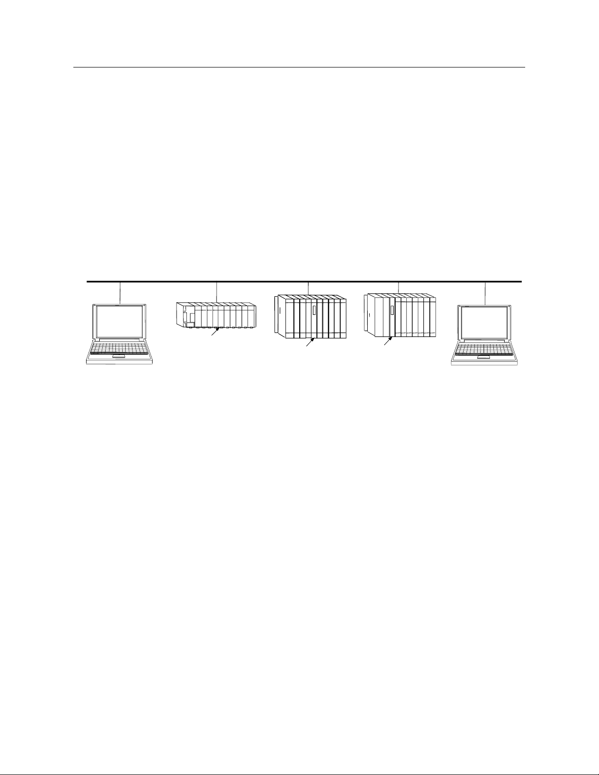
A PACSystems Ethernet interface enables a PACSystems controller to communicate with
other PACSystems equipment and with Series 90 and VersaMax controllers. The Ethernet
interface provides TCP/IP communications with other PLCs, host computers running the
Host Communications Toolkit or CIMPLICITY software, and computers running the TCP/IP
version of the programming software. These communications use the proprietary SRTP
and Ethernet Global Data (EGD) protocols over a four-layer TCP/IP (Internet) stack.
The Ethernet interface has SRTP client/server capability. As a client, the interface can
initiate communications with other PLCs that contain Ethernet interfaces. This is done
from the PLC ladder program using the COMMREQ function. As a server, the Ethernet
interface responds to requests from devices such as PLC programming software, a Host
computer running an SRTP application, or another PLC acting as a client.
Network
Connection
Ethernet Cable
Host Computer or Control
Device running a Host
Communications Toolkit
Ethernet
Interface
PACSystems and Series 90 PLCs
Computer Running
Programming Software-
TCP/IP Ethernet
Ethernet
Interface
Ethernet
Interface
Network
Connection
Figure 1: Ethernet Connection System Diagram
1.3.1 RX3i Rack-Based Ethernet Interfaces – Features
▪ Full RX3i Controller programming and configuration services with inactivity timeout
▪ Periodic data exchange using Ethernet Global Data (EGD)
▪ EGD Commands to read and write PLC and EGD exchange memory over the network
▪ TCP/IP communication services using SRTP
▪ SRTP Client (Channels)
▪ Modbus TCP Server, supporting Modbus Conformance classes 0, 1, and 2
▪ Modbus TCP Client, supporting Modbus Conformance classes 0, 1, and Function Codes 15, 22, 23,
and 24 for Conformance class 2
▪ Redundant IP Addressing capability
Page 19

PACSystems™ RX3i and RSTi-EP TCP/IP Ethernet Communications User Manual Section 1
GFK-2224Y August 2019
Introduction 6
▪ Comprehensive station management and diagnostic tools
▪ Extended controller connectivity via IEEE 802.3 CSMA/CD 10 Mbps, 100M bps and 1000 Mbps
Ethernet LAN port connectors
▪ Network switch that has Auto negotiate, Sense, Speed, and crossover detection
▪ Protocol is stored in flash memory in the Ethernet interface and is easily upgraded through the CPU
serial port.
▪ Communications with remote PLCs and other nodes reachable through routers. The gateway IP
address must be configured.
1.3.2 RX3i & RSTi-EP Embedded Ethernet Interface - Features
▪ Periodic data exchange using Ethernet Global Data (EGD).
▪ Full RX3i controller programming and configuration services with inactivity timeout
▪ TCP/IP communication services using SRTP.
▪ SRTP Client (Channels)
▪ Modbus TCP Server, supporting Modbus Conformance classes 0, 1, and 2.
▪ Modbus TCP Client, supporting Modbus Conformance classes 0, 1, and Function Codes 15, 22, 23,
and 24 for Conformance class 2.
▪ Communications with remote PLCs and other nodes reachable through routers. The Gateway IP
address must be configured.
▪ Comprehensive station management and diagnostic tools. For supported commands, refer to the
PACSystems TCP/IP Ethernet Communications Station Manager User Manual, GFK-2225J or later.
1.3.2.1 CPE302/CPE305/CPE310
▪ Extended controller connectivity via IEEE 802.3 CSMA/CD 10 Mbps and 100 Mbps Ethernet LAN port
connectors.
▪ Network switch that has Auto negotiate, Sense, Speed, and crossover detection.
▪ Direct connection to Base-T (twisted pair) network switch, hub, or repeater without an external
transceiver.
Page 20

PACSystems™ RX3i and RSTi-EP TCP/IP Ethernet Communications User Manual Section 1
GFK-2224Y August 2019
Introduction 7
CPE330/CPE400/CPL410
• Two independent 10/100/1000 Ethernet LANs under the control of the embedded RX3i PLC. Port 1
attaches to LAN1 through a dedicated RJ45 connector. Port 2 attaches to LAN2 through a pair of
internally-switched RJ45 connectors. Space is provided to mark in the two corresponding IP
addresses.
• The embedded Ethernet interface permits the CPU to support two LANs.
• CPE400 has a third Ethernet port (located on the underside) which is under the control of Field
Agent.
• CPL410 also has a third Ethernet port (located on the underside) which is under the control of the
Linux OS.
RSTi-EP CPE100/CPE115
• Two independent 10/100 Ethernet LANs. Port 1 attaches to LAN1 through a dedicated RJ45
connector. Port 2 attaches to LAN2 through three internally-switched RJ45 connectors.
• The embedded Ethernet interface permits the CPU to support two LANs.
Refer to the PACSystems RX7i, RX3i and RSTi-EP CPU Reference Manual, GFK-2222,
specifically to the section, RX3i CPU Features and Specifications for RX3i CPUs & RSTi-EP
CPU Features and Specifications for RSTi-EP CPU, for a detailed list of features and
specifications.
Page 21

PACSystems™ RX3i and RSTi-EP TCP/IP Ethernet Communications User Manual Section 1
GFK-2224Y August 2019
Introduction 8
1.3.3 Ethernet Interface Specifications
RX3i Rack-Based Ethernet
Interface Modules
Connectors
IC695ETM001-Jx or earlier
- Two RJ45 connectors
- One 9-pin d-sub male serial connector (Station Manager port)
IC695ETM001-Kxxx
Three autosensing RJ45 ports
LAN
IC695ETM001-Jx or earlier:
IEEE 802.3 CSMA/CD Medium Access Control 10/100 Mbps
IC695ETM001-Kxxx:
IEEE 802.3 CSMA/CD Medium Access Control 10/100/1000 Mbps
Number of IP addresses
One
Maximum number of
simultaneous connections
▪ A maximum of 48 SRTP Server total connections
▪ A maximum of 16 Modbus/TCP Server connections
▪ A maximum of 32 communication channels. (Each channel may be an
SRTP Client or a Modbus/TCP Client. Any given channel can be assigned
to only one protocol at a time.)
Embedded Ethernet Switch
Yes – Allows daisy chaining of Ethernet nodes.
Serial Port
IC695ETM001-Jx
Station Mgr Port: RS-232 DCE, 1200 - 115200 bps.
IC695ETM001-Kxxx
Not applicable.
Station Manager
IC695ETM001-Jx
Access via local serial port or remote UDP. Refer to the PACSystems TCP/IP
Ethernet Communications Station Manager User Manual, GFK-2225J or later,
for supported commands.
IC695ETM001-Kxxx
Station Manager serial port has been replaced by the front panel Ethernet
port
Maximum ETM001 Modules
per CPU rack
Eight positions
Page 22

PACSystems™ RX3i and RSTi-EP TCP/IP Ethernet Communications User Manual Section 1
GFK-2224Y August 2019
Introduction 9
1.3.3.1 RX3i Embedded Interface
Connector
CPE302/CPE305 & CPE310: One RJ45 connector
CPE330: Three RJ45 connectors
CPE400: Six RJ45 connectors: five on front for LAN1, LAN2 & LAN3; one EFA
on underside. (There is also a serial RJ45 on underside, marked COM1.)
CPL410: Six RJ45 connectors: five on front for LAN1, LAN2 & LAN3; one ETH
on underside. (There is also a serial RJ45 on underside, marked COM1.)
CPE100/CPE115: Four RJ45 connectors
LAN
IEEE 802.3 CSMA/CD Medium Access Control 10/100/1000 Mbps
CPE302/CPE305 & CPE310 has one 10Base-T/100Base-TX Port (LAN1)
CPE330 has two independent 10/100 Mbps Ethernet LANs:
▪ The top Ethernet port attaches to LAN1 using a dedicated RJ45
connector
▪ The bottom two Ethernet ports attach to LAN2 using a pair of internally-
switched RJ45 connectors
CPE400 supports four independent 10/100/1000 Ethernet LANs which are
under the control of the embedded RX3i PLC.
▪ LAN1 attaches via the upper, dedicated RJ45 front-panel connector.
▪ LAN2 and LAN3
1
each attach via a pair of internally-switched RJ45 front-
panel connectors.
▪ The fourth LAN, labeled EFA (Embedded Field Agent), is located on the
underside, and is specifically used for Field Agent connectivity.
CPL410 supports four independent 10/100/1000 Ethernet LANs which are
under the control of the embedded RX3i PLC.
▪ LAN1 attaches via the upper, dedicated RJ45 front-panel connector.
▪ LAN2 and LAN3 each attach via a pair of internally-switched RJ45 front-
panel connectors.
The fourth LAN, labeled ETH (Ethernet), is located on the underside, and is
under the control of the embedded Linux Operating System.
CPE100/CPE115 supports two independent 10/100 Ethernet LANs located
on the front panel.
▪ LAN1 attaches via the upper, dedicated RJ45 connector.
▪ LAN2 attach via three internally-switched RJ45 connectors.
Number of IP addresses
CPE302/CPE305 & CPE310: One IP address
CPE330 has two IP addresses
CPE400 has four IP addresses (one for EFA, three for Ethernet LANs)
CPL410 has four IP addresses (one for ETH, three for Ethernet LANs)
CPE100/CPE115 has two IP addresses
1
CPE400 firmware version 9.30 supports Redundancy via LAN3. No LAN components other than the two Redundant
CPUs are permitted on LAN3. All firmware versions of CPL410 support the same feature.
Page 23

PACSystems™ RX3i and RSTi-EP TCP/IP Ethernet Communications User Manual Section 1
GFK-2224Y August 2019
Introduction 10
Maximum number of
connections
For CPE302/CPE305 & CPE310 LAN1:
▪ Up to 32 SRTP Server connections, includes:
▪ Up to 16 simultaneous Modbus/TCP Server connections.
▪ Up to 16 Client channels. (Each channel may be an SRTP Client or a
Modbus/TCP Client. Any given channel can be assigned to only one
protocol at a time.)
▪ OPC UA Server with support for up to 5 concurrent sessions with up to
10 concurrent variable subscriptions and up to 12,500 variables.
▪ Up to 255 simultaneous Class 1 Ethernet Global Data (EGD) exchanges.
For CPE330, CPE4001 and CPL410, the embedded Ethernet permits the CPU
to support LAN1 and LAN2 with:
▪ Up to 48 simultaneous SRTP Server connections, and
▪ Up to 16 simultaneous Modbus/TCP Server connections
▪ Up to 32 Clients are permitted; each may be SRTP or Modbus/TCP
▪ OPC UA Server with support for up to 5 concurrent sessions with up to
10 concurrent variable subscriptions and up to 12,500 variables
▪ Up to 255 simultaneous Class 1 Ethernet Global Data (EGD) exchanges.
For CPE100/CPE115, the embedded Ethernet permits the CPU to support
LAN1 and LAN2 with:
▪ Up to 16 simultaneous SRTP Server connections, and
▪ Up to 8 simultaneous Modbus/TCP Server connections
▪ Up to 8 Clients are permitted; each may be SRTP or Modbus/TCP
▪ Up to 8 simultaneous Class 1 Ethernet Global Data (EGD) exchanges.
Station Manager
Access remote UDP Refer to the PACSystems TCP/IP Ethernet Communications
Station Manager User Manual, GFK-2225J or later for supported commands.
1.3.4 Ethernet interface Ports
The PACSystems Ethernet interface use auto-sensing 10Base-T/100Base-TX/1000Base-T
RJ45 shielded twisted pair Ethernet ports for connection to either a 10BaseT, 100BaseTX
or 1000Base-T IEEE 802.3 network.
The RX3i CPE330, CPE400 and CPL410 embedded Ethernet interface additionally
supports 1000Base-T IEEE 802.3 connections.
The RX3i Controllers with embedded Ethernet provide one such port; dedicated Ethernet
interface Modules provide two.
The port automatically senses the speed (10 Mbps, 100 Mbps or 1000Mbps), duplex
mode (half-duplex or full-duplex) and cable configuration (straight-through or crossover)
attached to it with no intervention required.
Page 24

PACSystems™ RX3i and RSTi-EP TCP/IP Ethernet Communications User Manual Section 1
GFK-2224Y August 2019
Introduction 11
1.3.4.1 Ethernet Media
The Ethernet interface can operate directly on 10Base-T/100Base-TX/1000Base-T media
via its network ports.
10Base-T: 10Base-T uses a twisted pair cable of up to 100 meters in length between each
node and a switch, hub, or repeater. Typical switches, hubs, or repeaters support
connections in a start topology.
100Base-TX: 100Base-TX uses a cable of up to 100 meters in length between each node
and a switch, hub, or repeater. The cable should be data grade Category 5 unshielded
twisted pair (UTP) or shielded twisted pair (STP) cable. Two pairs of wire are used, one for
transmission, and the other for collision detection and receive. Typical switches, hubs, or
repeaters support 6 to 12 nodes connected in a star wiring topology.
1000Base-T: 1000Base-T uses a cable of up to 100 meters in length between each node
and a switch, hub, or repeater. The cable should be data grade Category 6 unshielded
twisted pair (UTP) or shielded twisted pair (STP) cable or better. Four pairs of wire are
used which are designed to operate over 4-pair UTP cable and supports full-duplex data
transfer at 1000Mbps. Typical switches, hubs, or repeaters support 6 to 12 nodes
connected in a star wiring topology.
1.3.5 Station Manager
The built-in Station Manager function of the Ethernet interface provides on-line
supervisory access to the Ethernet interface, through the Station Manager port or over
the Ethernet cable. Station Manager services include:
▪ An interactive set of commands for interrogating and controlling the station.
▪ Unrestricted access to observe internal statistics, an exception log, and
configuration parameters.
▪ Password security for commands that change station parameters or operation.
For remote Station Manager operation over the Ethernet network, the Ethernet interface
uses IP addressing. A PACSystems Ethernet interface cannot send or receive remote
Station Manager messages sent to a MAC address.
Refer to the PACSystems TCP/IP Ethernet Communications Station Manager User Manual,
GFK-2225 for complete information on the Station Manager.
Page 25

PACSystems™ RX3i and RSTi-EP TCP/IP Ethernet Communications User Manual Section 1
GFK-2224Y August 2019
Introduction 12
1.3.6 Firmware Upgrades
PACSystems Ethernet interfaces receive their firmware upgrades indirectly from the RX3i
CPU using the WinLoader software utility. WinLoader is supplied with any updates to the
Ethernet interface software. The user connects WinLoader to the PLC CPU serial port and
specifies the target module by its Rack/Slot location.
For the CPU module, the embedded Ethernet interface firmware is upgraded along with
the rest of the CPU firmware. WinLoader seamlessly upgrades first the CPU firmware and
then the embedded Ethernet firmware without user intervention. Each Ethernet interface
module’s firmware must be explicitly upgraded by specifying the rack and slot location of
the module to the WinLoader utility.
Firmware upgrades for the CPE330, CPE400, CPL410 and CPE100/CPE115 are performed
over Ethernet using a web browser. This method provides enhanced security features.
Instructions for the procedure are included in the corresponding upgrade kit
documentation. The WinLoader utility will not work with the CPE330, CPE400, CPL410 or
CPE100/CPE115 CPUs.
1.3.7 SRTP Client (Channels)
SRTP Client allows the PACSystems PLC to initiate data transfer with other SRTP-capable
devices on the network. SRTP channels can be set up in the PLC application program.
SRTP supports COMMREQ-driven channel commands to establish new channels, abort
existing channels, transfer data on an existing channel, and retrieve the status of an
existing channel.
Any given channel can be assigned to only one protocol at a time. For the number and
combinations of channels supported, refer to Section 1.3.3 Ethernet Interfaces for
PACSystems Controllers.
1.3.8 Modbus TCP Client (Channels)
Modbus TCP Client allows the PACSystems PLC to initiate data transfer with other Modbus
TCP server devices on the network. Modbus TCP channels can be set up in the application
program. The Modbus TCP Client supports COMMREQ-driven channel commands to open
new channels, close existing channels, and transfer data on an existing channel.
Any given channel can be assigned to only one protocol at a time. For the number and
combinations of channels supported, refer to Section 1.3 Ethernet Interfaces for
PACSystems Controllers.
Page 26

PACSystems™ RX3i and RSTi-EP TCP/IP Ethernet Communications User Manual Section 1
GFK-2224Y August 2019
Introduction 13
1.3.9 Ethernet Global Data (EGD)
▪ EGD Classes:
• EGD Class 1 is configured exchanges with no logic control of EGD operation.
o Supported in
CPE302/CPE305/CPE310/CPE330/CPE400/CPL410/CPE100/CPE115
• EGD Class 2 is EGD Commands which are logic-driven EGD exchanges using
COMMREQs.
o Supported on IC695ETM001
o Not supported on embedded Ethernet ports of
CPE302/CPE305/CPE310/CPE330/CPE400/CPL410/CPE100/CPE115 at
time of publication
Each PACSystems RX3i CPU supports up to 255 Class 1 simultaneous EGD exchanges and
RSTi-EP CPU CPE100/CPE115 supports up to eight Class 1 simultaneous EGD exchanges.
EGD exchanges are configured using the programmer and stored into the PLC. Both
Produced and Consumed exchanges can be configured. PACSystems Ethernet interfaces
support both selective consumption of EGD exchanges and EGD exchange production
and consumption to the broadcast IP address of the local subnet.
Note: For Broadcast addressing a Subnet value of 0.0.0.0 is NOT supported.
1.3.9.1 Synchronizing EGD Timestamps with SNTP
Both the ETM001-Jx and -Kxxx Ethernet interfaces can be configured to use Simple
Network Time Protocol (SNTP) to synchronize the timestamps of produced EGD
exchanges.
With an appropriate PME Hardware Configuration, the embedded Ethernet interface on
the CPE302, CPE305, CPE310, CPE330, CPE400 and CPL410 will also support SNTP. For
more information on PME Hardware Configuration, please refer to Section 4.1.3,
Configuring the Ethernet Interface Parameters.
Note: The RSTi-EP CPE100/CPE115 does not support SNTP.
Ethernet interface
module
SNTP Support
ETM001-Jx
Yes, with PME Hardware Configuration
(default configuration without using AUP file)
ETM001-Kxxx
Yes, with PME Hardware Configuration
CPU
SNTP Support
CPL410
Yes, with PME Hardware Configuration
Page 27

PACSystems™ RX3i and RSTi-EP TCP/IP Ethernet Communications User Manual Section 1
GFK-2224Y August 2019
Introduction 14
CPE400
Yes, with PME Hardware Configuration
CPE330
Yes, with PME Hardware Configuration
CPE302/CPE305/
CPE310
Yes, with PME Hardware Configuration
CPE100/CPE115
Not supported
1.3.10 SRTP Inactivity Timeout
Starting with Release 6.00, the PACSystems Ethernet interface supports inactivity
timeout checking on Secure Real-Time Transport Protocol (SRTP) server connections with
any PAC Machine Edition (PME) PLC programmer. Until the server connection is removed,
other programmers cannot switch from Monitor to Programmer mode. With inactivity
timeout checking, the Ethernet interface removes an abandoned SRTP server connection
and all its resources when there is no activity on the connection for the specified timeout
interval. Without the SRTP inactivity timeout, an abandoned SRTP server connection
persists until the underlying TCP connection times out (typically 7 minutes). All network
PME programmer connections initially use an SRTP inactivity timeout value of 30 seconds
(as set by the "vconn_tout" AUP parameter).
PME programmers can override the initial timeout value on a specified server connection.
Typically, the PME programmer sets the SRTP inactivity timeout to 20 seconds. An
inactivity timeout value of zero disables SRTP inactivity timeout checking.
The SRTP server uses an internal inactivity timeout resolution of 5 seconds. This has two
effects. First, any non-zero inactivity timeout value (either set by AUP parameter or
overridden on the programmer connection) is rounded up to the next multiple of 5
seconds. Additionally, the actual SRTP inactivity timeout detection for any individual
connection may vary up to an additional 5 seconds. The actual inactivity detection time
will never be less than the specified value.
Note: The SRTP inactivity timeout applies only to programmer connections over SRTP. It
does not affect HMI or SRTP channels.
1.4 Ethernet Redundancy Operation
The Redundant IP feature allows a single IP address to be assigned to two Ethernet
modules, where the two modules are in two different PLCs configured as a redundant
system. This functionality has been integrated into the product line, as follows:
CPU
Embedded Ethernet Redundancy
Support
Support via Ethernet
Module (ETM001-Jx
or ETM001-Kxxx)
CPL410
All firmware versions
Not supported
CPE400
Embedded Ethernet requires CPU
Firmware Version 9.30
Not supported
Page 28
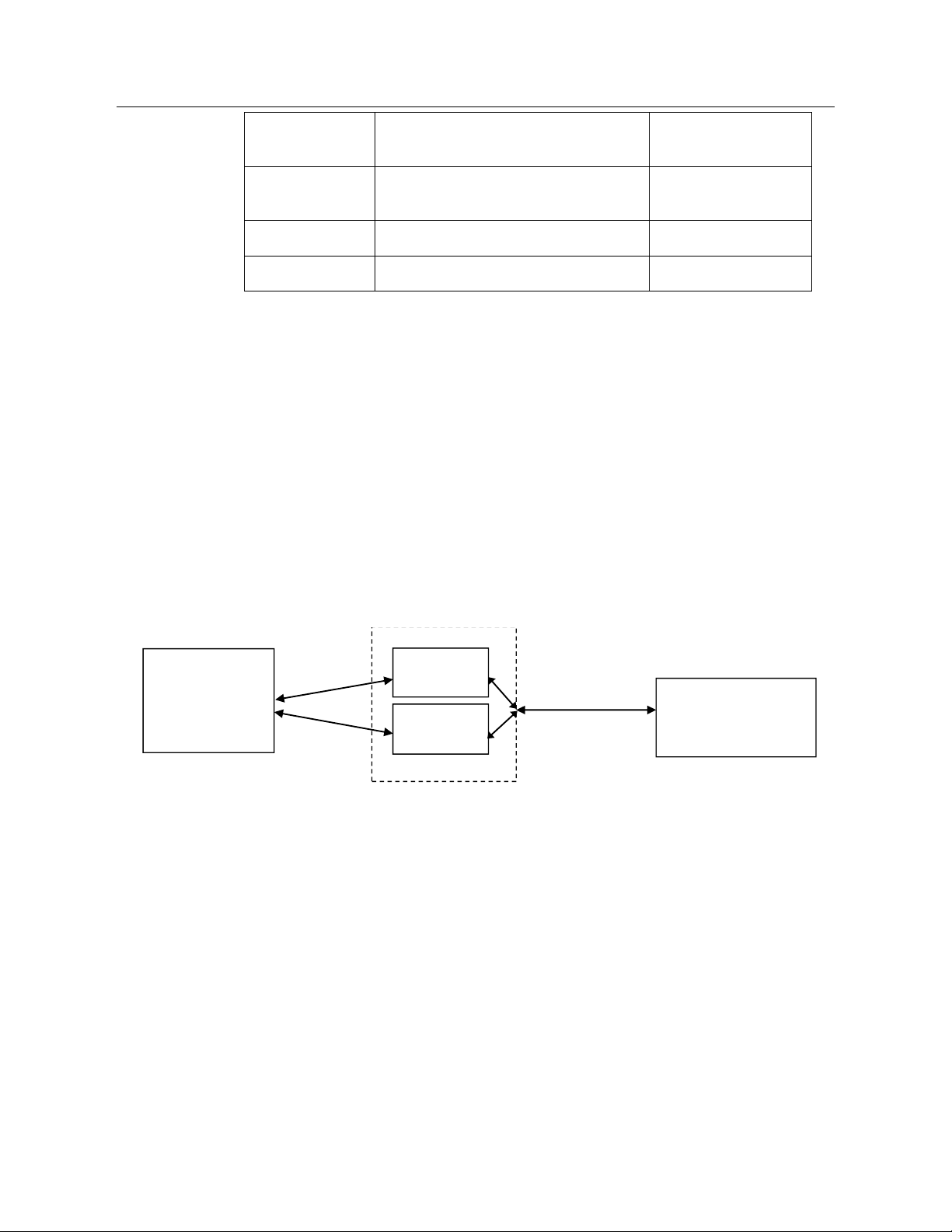
PACSystems™ RX3i and RSTi-EP TCP/IP Ethernet Communications User Manual Section 1
GFK-2224Y August 2019
Introduction 15
CPE330
Embedded Ethernet requires CPU
Firmware Version 8.70
Supported
CPE302/CPE305/
CPE310
Not supported
Not supported
CPE100/CPE115
Not supported
Not supported
CRU320
Not supported
Supported
The Redundant IP Address is configured in addition to the normal unique (direct) IP
address of each interface.
Only one of the two Ethernet interfaces that share the Redundant IP address may use the
Redundant IP address at any time; this is the “active” unit. When commanded by its PLC
CPU, this Ethernet interface activates the Redundant IP address and starts responding to
the Redundant IP address in addition to its direct IP address. The active unit continues
responding to the Redundant IP address until it is commanded to deactivate the
Redundant IP or until the Ethernet interface determines that it has lost communications
with the PLC CPU.
The backup unit does not initiate communications or respond on the network using the
Redundant IP address. It can only use the Redundant IP address if it is commanded by its
CPU to become the active unit.
Both the active and backup unit may continue to use their individual direct IP addresses,
permitting programmer connection to the active or backup PLC at any time.
PLC A
PLC B
Redundant System
Programmer
Remote host
(HMI, PLC, etc.)
Redundant
IP Address
Direct IP
Addresses
Figure 2: Ethernet Operation in Redundancy Mode
Note: The Redundant IP feature is supported by Hot Standby (HSB) CPUs and non-HSB
CPUs. To use this feature, be sure to toggle Enable Redundancy for the target CPU.
1.4.1 Hot Standby (HSB) CPU Redundancy
An HSB system uses redundant CPUs to provide the coordination between the PLC units
in the system and determine which is the active unit and which is the backup unit. HSB
redundancy requires dedicated links to provide communications between the units in a
redundancy system. For information about HSB architectures, refer to the PACSystems Hot
Standby CPU Redundancy User’s Guide, GFK-2308.
Page 29
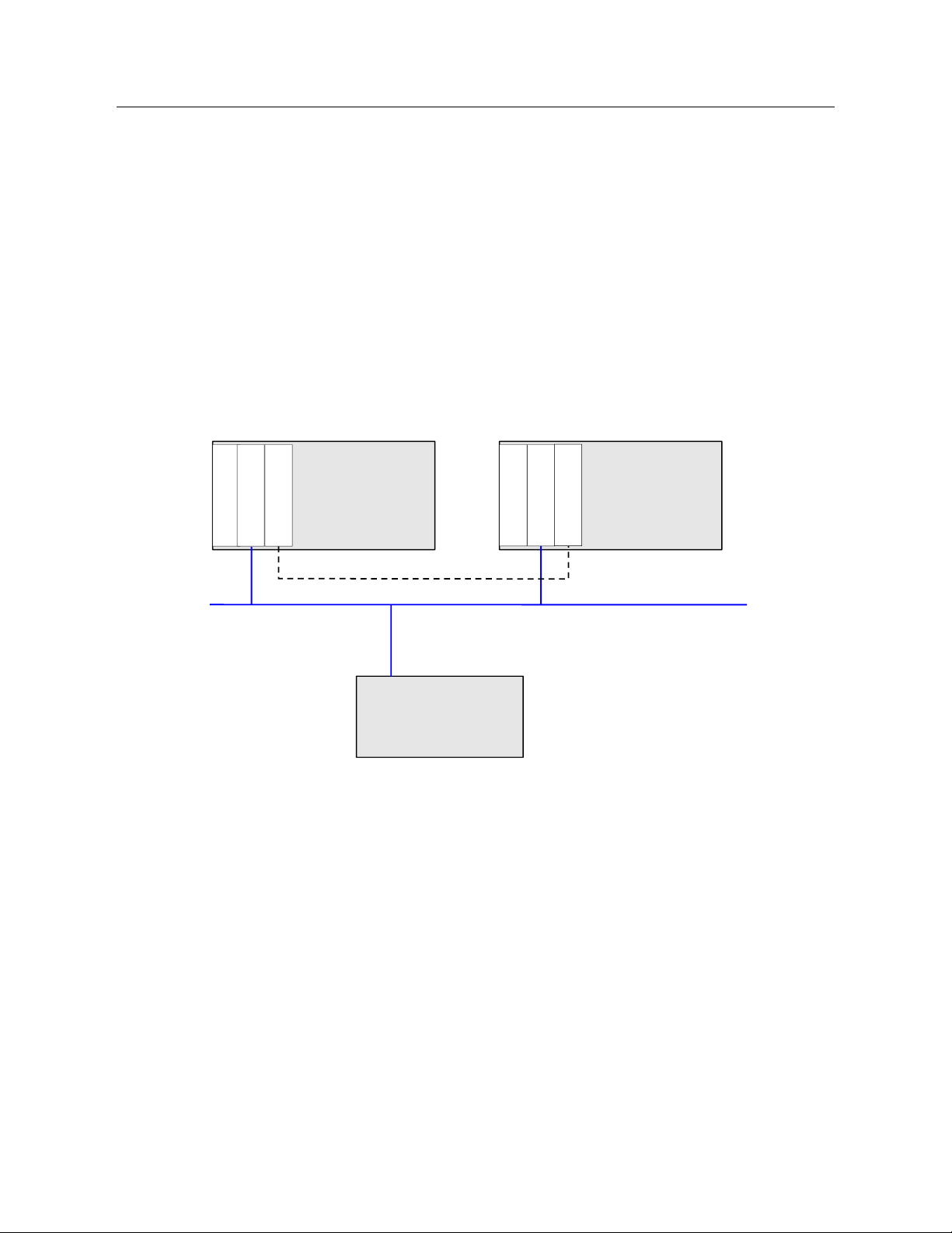
PACSystems™ RX3i and RSTi-EP TCP/IP Ethernet Communications User Manual Section 1
GFK-2224Y August 2019
Introduction 16
1.4.2 Non-HSB Redundancy
Non-HSB redundancy systems use RX3i CPUs that do not have specialized firmware for
controlling redundancy operations. (These CPUs have a “CPE” or “CPU” designation.) In
these systems, the application logic coordinates between CPUs that act as redundant
partners, and determines which CPU is the active unit and which are backup units. Figure
3 illustrates the use of the redundant IP feature in a non-HSB redundancy system. Two
non-HSB CPUs (designated primary and secondary) are linked by a communications
connection. An Ethernet interface in each controller is configured with Redundant IP
enabled so that they share a Redundant IP address. As in an HSB system, only the active
Ethernet interface can communicate through the Redundant IP address to produce EGD
exchanges or to initiate Channel operations.
The application logic must monitor the status of the Ethernet modules in the system to
manage the active/backup status of each controller.
C
P
U
Primary Controller
C
P
U
Secondary Controller
Ethernet
E
T
M
E T M
Remote Device
L
I
N
K
L
I
N
K
Figure 3: Basic Non-HSB System with Redundant IP
1.4.3 Effect of Redundancy Role Switching on Ethernet Communications
When a redundancy role-switch occurs, Ethernet communications switch to the backup
unit, which has no knowledge of any communication state at the previously-active unit.
The application must include logic to detect loss of communication during a redundancy
role switch and to then reinitiate communication.
Remote hosts on the network view redundant systems as a single PLC with high reliability;
the remote host only prioritizes the active unit. By using the Redundant IP address, the
remote host always communicates with the active unit. When a redundancy role switch
occurs, the formerly-active PLC gives up ownership of the Redundant IP address and takes
down all connection-oriented communications currently using the Redundant IP address.
The applications in the redundant system and remote hosts must reestablish any such
communications; the new Redundant IP connections will use the newly active PLC.
Page 30

PACSystems™ RX3i and RSTi-EP TCP/IP Ethernet Communications User Manual Section 1
GFK-2224Y August 2019
Introduction 17
The programmer can still communicate directly with each PLC in the redundant system
(for example, to store new logic or configuration) using the direct IP address of each
Ethernet interface.
1.4.3.1 Role Switching in HSB Redundancy Systems
In HSB redundancy systems, a role switch is initiated automatically by the redundant CPU
when one of the following occurs:
▪ An active unit detects a fatal fault
▪ An active unit is placed in Stop mode
▪ An active unit is powered off
▪ An HSB role switch is initiated manually or by the application logic
To perform a role switch manually in redundant systems which employ RMX modules,
toggle the Role Switch button located on the front panel of the RMX module.
CPE400/CPL410 permits the operator to manually perform a role switch via the OLED
display menu, using the RDN Command feature.
For additional information about role switches in HSB systems, refer to the PACSystems
Hot Standby CPU Redundancy User’s Guide, GFK-2308.
1.4.3.2 Role Switching in Non-HSB Redundancy Systems
When redundant IP is enabled for an Ethernet module in a non-HSB CPU system, it is the
responsibility of application logic to set the redundancy mode of the Ethernet module.
The Set Application Redundancy Mode Service Request (SVC_REQ 55) instruction is used to
inform the Ethernet module of the current redundancy role of the host CPU. This
SVC_REQ should be used to provide redundancy role switch notification to all Ethernet
interfaces in the controller that are configured for redundant IP operation.
After commanding a role switch for an Ethernet interface, the application logic can
monitor the module’s LAN interface Status (LIS) block to determine when it has activated
the Redundancy IP address. For details about the LIS, refer to Section 12.6, Monitoring
the Ethernet Interface Status Bits.
Note: The application must allow sufficient time for Redundant IP activation (at least 120
ms) before commanding another redundancy role switch.
When an Ethernet interface recognizes that a redundant IP address has been configured
for it, the module sends a mail message to the CPU to register for redundancy role switch
notification. In non-HSB systems, the Ethernet interface is initially put into backup mode.
After power-up, the application logic must use a SVC_REQ to set the redundancy state to
the desired value. Once running, the CPU remembers the last commanded redundancy
role sent to that Ethernet interface. When an Ethernet interface is restarted, the CPU
automatically commands the Ethernet interface to its last redundancy state without
explicit action by the application logic.
1.4.3.3 Going to Stop Mode
When a non-HSB CPU goes to Stop mode, Ethernet interfaces that are configured for
redundant IP are automatically set to backup mode. When the CPU is subsequently
returned to Run mode, the Ethernet interfaces remain in backup mode until the
application logic sets the redundancy mode to active.
Page 31

PACSystems™ RX3i and RSTi-EP TCP/IP Ethernet Communications User Manual Section 1
GFK-2224Y August 2019
Introduction 18
1.4.3.4 Stop/IO Scan Enabled Mode
In this mode, I/O scanning including EGD service continues when the non-HSB CPU is
stopped. However, Ethernet interfaces configured for redundant IP operation are
automatically set to backup mode and normal EGD production for those interfaces is
stopped. Only the EGD exchanges with Produce in backup mode enabled are produced
while the CPU is in Stop/IO Scan Enabled mode. To stop production for all EGD produced
exchanges including Produce in backup mode exchanges, choose the Stop/IO Scan
Disabled mode of operation.
1.4.3.5 Commanding a Role Switch in a Non-HSB Redundancy System
Use the Set Application Redundancy Mode service request (SVC_REQ 55) with non-HSB
CPUs to request that the CPU send redundancy role switch commands to all Ethernet
interfaces in that PLC that are configured for redundant IP operation. For details on using
the Service Request function, refer to the PACSystems RX7i, RX3i and RSTi-EP CPU Reference
Manual, GFK-2222.
SVC_REQ 55 is recognized in non-HSB CPUs only. This service request sends a role switch
command to all Ethernet interfaces in the PLC that are configured for redundant IP
operation. The application must monitor the LAN interface Status (LIS) word for each
Ethernet interface to determine whether the Redundant IP address is active at that
interface.
SVC_REQ 55 has no effect on Ethernet interfaces that are not configured for redundant IP
operation.
1.4.4 SRTP Server Operation in a Redundancy System
Only the active unit maintains SRTP Server connections at the Redundant IP address and
can respond to SRTP requests. The backup unit does not respond to the Redundant IP
address. When an Ethernet interface changes from active to backup state, it takes down
all SRTP Server connections and their underlying TCP connections that use the Redundant
IP address.
Both the active and backup units maintain SRTP Server connections at the direct IP
address for network communication with the programmer. Other remote hosts should
use the Redundant IP address when communicating to a redundant system. Existing SRTP
Server connections at the direct IP address are not disturbed when the Ethernet interface
switches between active and backup states.
1.4.5 SRTP Client Operation in a Redundancy System
Only the active unit establishes and maintains SRTP Client connections (channels). The
backup unit does not initiate any SRTP Client operations. If SRTP Client operations are
attempted, a COMMREQ error status is returned to the local logic program. When the
Ethernet interface changes from active to backup state, it takes down all SRTP Client
connections and their underlying TCP connections.
Because it can take some time to take down a TCP connection, the redundant system
should reserve a spare SRTP Client connection for each connection using the Redundant
IP address. That will prevent temporary resource problems when establishing new SRTP
Page 32

PACSystems™ RX3i and RSTi-EP TCP/IP Ethernet Communications User Manual Section 1
GFK-2224Y August 2019
Introduction 19
Client connections to the new active unit while the previous connections to the old active
unit are being taken down.
1.4.6 Modbus TCP Server Operation in a Redundancy System
Only the active unit maintains Modbus TCP Server connections at the Redundant IP
address and can respond to Modbus TCP requests. The backup unit does not respond to
the Redundant IP address. When an Ethernet interface changes from active to backup
state, it takes down all Modbus TCP Server connections and their underlying TCP
connections that use the Redundant IP address.
Remote hosts should use the Redundant IP address when communicating to a redundant
system. Existing Modbus TCP Server connections at the direct IP address are not
disturbed when the Ethernet interface switches between active and backup states.
1.4.7 Modbus TCP Client Operation in a Redundancy System
Only the active unit establishes and maintains Modbus TCP Client connections (channels).
The backup unit does not initiate any Modbus TCP Client operations. If Modbus TCP Client
operations are attempted, a COMMREQ error status is returned to the local logic
program. When the Ethernet interface changes from active to backup state, it takes down
all Modbus TCP Client connections and their underlying TCP connections.
Because it can take some time to take down a TCP connection, the redundant system
should reserve a spare Modbus TCP Client connection for each connection using the
Redundant IP address. That will prevent temporary resource problems when establishing
new Modbus TCP Client connections to the new active unit while the previous
connections to the old active unit are being taken down.
1.4.8 EGD Class 1 (Production & Consumption) in a Redundancy System
The active unit produces Ethernet Global Data exchanges to the network. The backup unit
produces only the EGD exchanges for which Produce in Backup Mode is enabled. When
the active Ethernet interfaces changes to backup, it stops production of all EGD
exchanges.
When configured for Redundant IP operation, the active and backup Ethernet interfaces
should also be configured to consume EGD exchanges via multicast host groups or the
local subnet broadcast address. This permits both the active and backup units to receive
the latest data from the network. Emerson does not recommend Unicast operation as the
backup unit is not recommended as it will not consume any unicast exchanges at the
Redundant IP address.
1.4.9 EGD Class 2 Commands in a Redundancy System
Remote hosts should use the Redundant IP address when communicating to a redundant
system. Only the active unit responds to EGD commands. The backup unit does not
respond to the Redundant IP address. When the active Ethernet interface changes to the
backup, any in-process EGD commands over the Redundant IP address are abandoned.
Page 33

PACSystems™ RX3i and RSTi-EP TCP/IP Ethernet Communications User Manual Section 1
GFK-2224Y August 2019
Introduction 20
When configured for Redundant IP operation, only the active unit sends EGD commands
on the network. If the backup unit tries to initiate any EGD commands, a COMMREQ error
status is returned to its application program. When the active Ethernet interfaces
changes to backup, any EGD commands in process are ended. Issuing EGD commands to
the direct IP address is not recommended; both the active and backup units will respond
to EGD commands received at the direct IP address.
1.4.10 Web Server Operation in a Redundancy System
Only the active unit processes Web server requests at the Redundant IP address and
responds to Web page requests. The backup unit does not respond to the Redundant IP
address. When the active Ethernet interface changes to backup, all Web server
connections and their underlying TCP connections are disrupted. The Web server
maintains its underlying TCP connection only long enough to process:
▪ A new Web page request
▪ A new TCP connection opened, used, or closed for each subsequent Web page
display or update.
The Redundant IP address is transparent to the Web remote browser unless a Web page
change or update is requested during the redundancy role switch. Any Web page request
in process over the Redundant IP when a role switch occurs is terminated.
Although not recommended, the remote browser may issue Web server requests to the
direct IP address. Both the active and backup units respond to Web server requests
received at the direct IP address. Remote Web browsers are expected to use the
Redundant IP address when communicating to a redundant system.
1.4.11 FTP Operation in a Redundancy System
2
FTP operations can transfer setup and configuration data to the Ethernet interface. Using
FTP operations for communication with the actual PLC application is not recommended.
FTP operations should only be performed using the direct IP address.
1.4.12 SNTP Operation in a Redundancy System
A PACSystems Ethernet interface can operate as an SNTP client only, which enables the
interface to only receive broadcast time messages from an SNTP Server on the network.
SNTP operation is unaffected by the current Ethernet redundancy state or by redundancy
role switches.
1.4.13 Remote Station Manager Operation in a Redundancy System
The remote Station Manager should respond to the direct IP address whether the unit is
active or backup or whether the Redundant IP is configured.
2
FTP is not supported by ETM001-Kxxx
Page 34

PACSystems™ RX3i and RSTi-EP TCP/IP Ethernet Communications User Manual Section 1
GFK-2224Y August 2019
Introduction 21
Only the active unit responds to remote Station Manager commands at the Redundant IP
address. The backup unit does not respond to the Redundant IP address. (Station
Manager responses from the Redundant IP address can be misleading because it is
difficult to determine which Ethernet interface is responding.)
1.4.14 IP Address Configuration in a Redundancy System
Redundancy systems should explicitly configure both the direct IP address and the
Redundant IP address. Do not set up the direct IP address via BOOTP.
The Redundant IP address must be configured on the same local sub-network as the
direct IP address and gateway IP address (if used).
Page 35

PACSystems™ RX3i and RSTi-EP TCP/IP Ethernet Communications User Manual Section 2
GFK-2224Y August 2019
Installation and Start-up: RX3i/RSTi-EP Embedded Interface 22
Section 2: Installation and Start-up: RX3i/RSTi-EP Embedded Interface
The RX3i CPUs with CPExxx designation (CPE302, CPE305, CPE310, CPE330 and CPE400),
the CPL410 and RSTi-EP CPE100/CPE115 provide an embedded Ethernet interface for
programmer communications. This section describes user features and provides basic
installation and startup procedures for this interface.
▪ Ethernet Interface Controls and Indicators
▪ Module Installation
▪ Connection to a 10Base-T/100Base-TX Network (all CPExxx) or to a 1000Base-T
(CPE330, CPE400 and CPL410 only)
▪ Pinging TCP/IP Ethernet interfaces on the Network
2.1 RX3i/RSTi-EP Embedded Ethernet Interface Indicators
Many of the Ethernet interfaces feature Ethernet ports with two LED indicators, 100 and
LINK. The 100 LED indicates the network data speed (10 or 100 Mb/sec). This LED is lit if
the network connection at that network port is 100 Mbps.
The LINK LED indicates the network link status and activity. This LED is lit when the link is
physically connected. It blinks when traffic is detected at that network port.
2.1.1 Ethernet Port LEDs Operation
2.1.1.1 CPE302/CPE305/CPE310 Ethernet LED Operation
LED
LED State
On
Blinking
Off
Ethernet Port State
100
On, Green
Network data speed is 100 Mbps.
Off
Network data speed is 10 Mbps.
LINK
On, Amber
The link is physically connected.
Blinking, Amber
Traffic is detected at the port.
Off
The Ethernet port is not physically connected.
Page 36

PACSystems™ RX3i and RSTi-EP TCP/IP Ethernet Communications User Manual Section 2
GFK-2224Y August 2019
Installation and Start-up: RX3i/RSTi-EP Embedded Interface 23
2.1.1.2 CPE330 Ethernet LED Operation
LED
LED State
Operating State
LINK
(upper)
On Green
The corresponding link is physically connected.
Blinking
Green
Traffic is detected at the corresponding port.
Off
No connection detected at corresponding port.
1 Gbps
(lower)
On Amber
(LAN1) or
Corresponding network data speed is 1 Gbps.
On Green
(LAN2)
Off
Corresponding network data speed is 100 Mbps or 10 Mbps.
2.1.1.3 CPE400/CPL410 Front Panel Ethernet LED Operation (LAN1,
LAN2, LAN3)
LED
LED State
Operating State
Link
Status
(upper)
On Green
The corresponding link has been established.
Blinking
Green
Traffic is detected at the corresponding port.
Off
No connection established at corresponding port.
Link
Speed
(lower)
On Green
Corresponding data speed is 1 Gbps or 100 Mbps.
Off
Corresponding network data speed is 10 Mbps
2.1.1.4 CPE400 Underside Ethernet LED Operation (EFA)
LED
LED State
Operating State
Link
Status
(upper)
On Green
The corresponding link has been established.
Blinking
Green
Traffic is detected at the corresponding port.
Page 37

PACSystems™ RX3i and RSTi-EP TCP/IP Ethernet Communications User Manual Section 2
GFK-2224Y August 2019
Installation and Start-up: RX3i/RSTi-EP Embedded Interface 24
LED
LED State
Operating State
Off
No connection established at corresponding port.
Link
Speed
(lower)
On Green
Corresponding network data speed is 1 Gbps.
On Yellow
EFA port only: network data speed is 100 Mbps
Off
Corresponding network data speed is 10 Mbps
2.1.1.5 CPL410 Underside Ethernet LED Operation (ETH)
LED
LED State
Operating State
Link
Status
(upper)
On Green
The corresponding link has been established.
Blinking
Green
Traffic is detected at the corresponding port.
Off
No connection established at corresponding port.
Link
Speed
(lower)
On Green
Corresponding network data speed is 1 Gbps.
On Yellow
GPOS port only: network data speed is 100 Mbps
Off
Corresponding network data speed is 10 Mbps
2.1.1.6 CPE100/CPE115 Ethernet LED Operation (LAN1, LAN2)
LED
LED State
Operating State
Link
Speed
(upper)
On Amber
Corresponding data speed is 100 Mbps.
Off
Corresponding network data speed is 10 Mbps
Link
Status
(lower)
On Green
The corresponding link has been established.
Blinking
Green
Traffic is detected at the corresponding port.
Off
No connection established at corresponding port.
Page 38

PACSystems™ RX3i and RSTi-EP TCP/IP Ethernet Communications User Manual Section 2
GFK-2224Y August 2019
Installation and Start-up: RX3i/RSTi-EP Embedded Interface 25
2.1.2 Module Installation
For general information about CPU module and system installation refer to the
PACSystems RX3i System Manual, GFK-2314 Sections 2 & 3.
For RSTi-EP CPU model refer RSTi-EP System Manual, GFK-2958D or later.
2.2 Ethernet Port Connector
The RX3i CPE302/CPE305 and CPE310 CPUs provide a
10Base-T/100Base-TX Ethernet network port connector.
When a CPE330 is configured as a CPU320, Ethernet
properties cannot be configured. However, the
embedded Ethernet ports may be used with the default IP Addresses.
2.2.1 Connection to a 10Base-T/100Base-TX Network
Either shielded or unshielded twisted pair cable may be attached to an Ethernet port. The
10Base-T/100Base-TX twisted pair cable must meet the applicable IEEE 802 standards.
Category 5 cable is required for 100Base-TX operation.
The Ethernet port automatically senses the speed (10 Mbps or 100 Mbps), duplex mode
(half-duplex or full-duplex) and cable configuration (straight-through or crossover)
attached to it with no intervention required.
2.2.2 10Base-T/100Base-TX Port Pinouts
Pin Number3
Signal
Description
1
TD+
Transmit Data +
2
TD–
Transmit Data –
3
RD+
Receive Data +
4
NC
No connection
5
NC
No connection
6
RD–
Receive Data –
7
NC
No connection
8
NC
No connection
Note: Pin assignments are provided for troubleshooting purposes only. 10BaseT/100Base-TX cables are readily available from commercial distributors. We recommend
purchasing rather than making 10Base-T/100Base-TX cables.
3
Pin 1 is at the bottom right of the Station Manager port connector as viewed from the front of the module.
Figure 4: RJ45 Connector
Page 39

PACSystems™ RX3i and RSTi-EP TCP/IP Ethernet Communications User Manual Section 2
GFK-2224Y August 2019
Installation and Start-up: RX3i/RSTi-EP Embedded Interface 26
The programmer is connected to the Ethernet interface through a 10Base-T or 100BaseTX network.
10BaseT/100Base-TX Twisted Pair Cable
Hub/Switch/Repeater
To other network devices
Ethernet Port
on RX3i/RSTi-EP
CPExxx
Programmer
Figure 5: Ethernet Cable Routing
2.3 Pinging TCP/IP Ethernet interfaces on the Network
PING (Packet InterNet Grouper) is the name of a program used on TCP/IP networks to test
reachability of destinations by sending them an ICMP echo request message and waiting
for a reply.
You should ping each installed Ethernet interface. When the Ethernet interface responds
to the ping, it verifies that the interface is operational and configured properly.
Specifically, it verifies that acceptable TCP/IP configuration information has been
downloaded to the interface.
For configuration details, including setting an initial IP address, refer to Section 4:.
2.3.1 Determining if an IP Address is Already Being Used
It is very important not to duplicate IP addresses. To determine if another node on the
network is using the same IP address:
1. Disconnect your Ethernet interface from the LAN.
2. Ping the disconnected interface’s IP address. If you get an answer to the ping, the
chosen IP address is already in use by another node. You must correct this situation by
assigning a unique IP address.
Note: This method does not guarantee that an IP address is not duplicated. It will not
detect a device that is configured with the same IP address if it is temporarily off the
network.
Page 40

PACSystems™ RX3i and RSTi-EP TCP/IP Ethernet Communications User Manual Section 3
GFK-2224Y August 2019
Installation and Start-up: Ethernet Module Interfaces 27
Section 3: Installation and Start-up: Ethernet Module Interfaces
▪ This chapter describes the features and basic installation procedures for Ethernet module interfaces
(ETM001-Jx and ETM001-Kxxx Ethernet interface Controls and Indicators
- Ethernet LEDs
- Ethernet Restart Pushbutton
- Front Panel Port
- Ethernet Port Connections
▪ Module Installation
- RX3i Rack-Based Ethernet Interface Modules
▪ Ethernet Port Connectors
- Embedded Switch
- Connection to a 10Base-T/100Base-TX/1000Base-T Network
▪ Station Manager Port
▪ Verifying Proper Power-Up of the Ethernet interface After Configuration
▪ Pinging TCP/IP Ethernet interfaces on the Network
Page 41

PACSystems™ RX3i and RSTi-EP TCP/IP Ethernet Communications User Manual Section 3
GFK-2224Y August 2019
Installation and Start-up: Ethernet Module Interfaces 28
3.1 Ethernet Module Interface Characteristics
There are two versions of the RX3i rack-based Ethernet module. Please note the differences in the table
below:
ETM001-Jx
ETM001-Kxxx
The ETM001-Jx Ethernet module provides:
• An Ethernet 10Base-T/100Base-TX
interface
• Two RJ-45 Ethernet ports. Either or both of
these ports can be attached to other
Ethernet devices. Each port automatically
sense the data rate (10 Mbps or 100
Mbps), duplex (half duplex or full duplex),
and cabling arrangement (straight through
or crossover) of the attached link.
• An embedded autodetect/autoswitch
Ethernet switch, which provides a means
to switch Ethernet data and allow daisy
chaining of Ethernet cabling, and provides
a method to automatically detect Ethernet
cable wire crossover.
The ETM001-Kxxx Ethernet module provides:
• An Ethernet 10Base-T/100BaseTX/1000Base-T interface
• Two RJ45 Ethernet ports located on
underside of module. Either or both ports
can attach to other Ethernet devices. Each
port automatically senses the data rate (10
Mbps/ 100 Mbps / 1000 Mbps), duplex
(half duplex or full duplex), and cabling
arrangement (straight through or
crossover) of the attached link.
• An embedded autodetect/autoswitch
Ethernet switch, which provides a means
to switch Ethernet data and allow daisy
chaining of Ethernet cabling, and provides
a method to automatically detect Ethernet
cable wire crossover.
Figure 6: ETM001-Jx Faceplate
Figure 7: ETM001-Kxxx Faceplate
Page 42

PACSystems™ RX3i and RSTi-EP TCP/IP Ethernet Communications User Manual Section 3
GFK-2224Y August 2019
Installation and Start-up: Ethernet Module Interfaces 29
3.1.1 Front Panel Port
The revised Ethernet module ETM001-Kxxx has been updated with an RJ45 port. The
Ethernet port supports Station Manager over IP. The default IP settings on the front panel
port are 10.10.0.100 subnet 255.255.255.0, gateway 0.0.0.0. Note: The Front panel port
does not support PACSAnalyzer only Station Manager.
3.1.2 Ethernet Port Connections
Each port on an ETM001 or ETM001-Kxxx operates independently, so devices that
operate at different speeds and/or duplex modes may be attached to the ports. By
default, all ports (even empty) are set for Automatic, which enables auto-negotiation for
the widest range of options supported by the port. The port connection speed can be
manually configured for slower speeds (10/100 Mbps) on the LAN1 tab in PME.
The ports can auto-negotiate to 10/100/1000 Mbps at full or half duplex. The speed can
be limited through Hardware Configuration (ETM001-Kxxx) or AUP settings (ETM001) to
10 Mbps or 100 Mbps. 1000 Mbps operation is only available with auto-negotiation on an
ETM001-Kxxx.
On the ETM001-Kxxx, half-duplex operation does not resend a packet that experiences a
collision at the hardware level. A collision is reported as a send or receive error and TCP
retries or other retry mechanisms must resend the data.
Embedded switches have limited memory to store packets. If there is a speed difference
between incoming traffic and outgoing traffic, there is an increased probability of
network traffic being dropped due to resource limitations. For example, if Port 1 has an
established 1000 Mbps link and Port 2 has an established 100 Mbps link, then traffic
traveling in from Port 1 and out Port 2 must be buffered since traffic is leaving at a
maximum rate 10 times slower than the maximum incoming rate. As the network loading
increases, the likelihood of data being dropped increases. Dropped packets are indicated
in the Station Manager Tallies. If there are significant dropped packets due to a speed
mismatch, it may be useful to limit the speed at the ETM001(-Kxxx) to match the larger
network. Speed changes in a system may be handled better with switches with more
packet buffer memory.
Figure 8: Ethernet Port Connectors on IC695ETM001-Kxxx
Page 43

PACSystems™ RX3i and RSTi-EP TCP/IP Ethernet Communications User Manual Section 3
GFK-2224Y August 2019
Installation and Start-up: Ethernet Module Interfaces 30
3.1.3 LEDs on the RX3i Ethernet Interface Module
LEDs provide an immediate visual indication of the operational state of the Ethernet
module and port link status. The LEDs and their operation are described in Chapter 2.1.1,
Ethernet Port LEDs Operation.
3.1.4 Ethernet LEDs
Ethernet modules have LEDs to indicate the state and status of the Ethernet interface:
ETM001-Jx
The Ethernet module’s Ethernet ports have two LEDs. The bottom LED is the link speed
LED. This LED is on for 100 Mbps and off for all other speeds. The top LED is the
link/activity LED. This will be on when there is a link at any speed. The top led will blink
when there is inbound or outbound traffic.
ETM001-Kxxx
The Ethernet module’s Ethernet ports will not have LEDs on the ports. Ethernet traffic
speed is indicated on the module’s front panel display, with discrete LEDs to indicate
10/100/1000 Mbps traffic.
3.1.4.1 LAN OK LED Operation
The LAN OK LED indicates access to the Ethernet network. During normal operation the
LAN OK LED blinks when data is being sent or received over the network directed to or
from the Ethernet interface. It remains on when the Ethernet interface is not actively
accessing the network, but the Ethernet physical interface is available and one or both of
the Ethernet ports is operational.
It is off otherwise unless firmware update is occurring.
3.1.4.2 LOG EMPTY LED Operation
The LOG EMPTY LED indicates the condition of the Ethernet interface in normal
operational mode. If the LOG EMPTY LED is off, an event has been entered into the
exception log and is available for viewing via the Station Manager interface. The LOG
EMPTY LED is on during normal operation when no events are logged.
In the other states, the LOG EMPTY LED is either off or blinking and helps define the
operational state of the module. For more information on LED behavior, refer to Section
12: Diagnostics.
3.1.4.3 Ethernet OK LED Operation
The Ethernet OK LED indicates whether the module can perform normal operation. This
LED is on for normal operation and flashing for all other operations. When a hardware or
unrecoverable runtime failure occurs, the ETM001-Jx will blink a two-digit error code
identifying the failure. The ETM001-Kxxx will blink a four-digit code. For assistance
troubleshooting errors , check Section 12.4, ETHERNET OK/OK LED Blink Codes for Hardware
Failures (ETM001-Jx). For assistance troubleshooting ETM001-Kxxx, please call Technical
Support.
Page 44

PACSystems™ RX3i and RSTi-EP TCP/IP Ethernet Communications User Manual Section 3
GFK-2224Y August 2019
Installation and Start-up: Ethernet Module Interfaces 31
3.1.4.4 Ethernet Port LEDs Operation (100Mb and Link/Activity)
The face of the Ethernet module is equipped with LEDs to indicate a physical connection
at the network port and network traffic speed.
Ethernet interface module
Link/Activity Location
Link/Activity Behavior
IC695ETM001
Two Ethernet ports (1A and 1B)
with two LED indicators (“100”
and “LINK”) are located at the
front of the interface module.
100 – LED indicates the network
data speed (10 or 100 Mbps).
When the LED state is ON, the
network connection at that
network port is 100 Mbps.
Link – LED indicates network link
status and activity. When the LED
state is ON, the link is physically
connected. When the LED blinks,
traffic is detected at that network
port. (Traffic at the port does not
indicate traffic is present at the
Ethernet interface. Traffic may be
introduced between ports of the
switch.)
IC695ETM001-Kxxx
Six single color green LEDs are
located on the face of the
interface module. The LEDs are
labeled 10, 100, 1000 for each of
the two Ethernet ports.
Two Ethernet ports (1 and2) are
located on the underside of the
interface module.
When the LED state is ON, the
link is physically connected.
When the LED blinks, traffic is
detected at that network port.
The LED label indicates the
network traffic speed.
Page 45

PACSystems™ RX3i and RSTi-EP TCP/IP Ethernet Communications User Manual Section 3
GFK-2224Y August 2019
Installation and Start-up: Ethernet Module Interfaces 32
3.1.5 Restart/Reset Pushbutton Operation
For PACSystems Ethernet interfaces, an Ethernet restart occurs when the restart/reset
pushbutton is pressed and released. The duration that the restart/reset pushbutton is
pressed determines the operation after the restart occurs.
If the Ethernet interface uses any optional Ethernet plug-in applications, these
applications are ordinarily started upon each power-up or restart. To restart the Ethernet
interface without starting any Ethernet plug-in applications, press and hold the Ethernet
restart/reset pushbutton between five and 10 seconds.
If the Ethernet interface is able to restart into firmware update operation, press and hold
the Ethernet restart pushbutton for more than 10 seconds. This is typically done during
troubleshooting to bypass possibly invalid firmware and allow valid firmware to be loaded
using WinLoader.
If the Ethernet interface uses the reset button to set a fixed temporary IP address, press
and hold the reset button for more than five seconds. Entering the IP Setup Mode will
display a light pattern on the front panel’s traffic speed LEDs.
Pushbutton-controlled restart operations are listed below, with the LED indications for
each:
Restart Operation
ETM001-Jx – Press and Hold
Restart Functionality
ETM001-Kxxx - Press and Hold
Reset Functionality
Restart the Ethernet interface
normally, and start any optional
Ethernet plug-in applications that
are being used.
Less than five seconds
Less than five seconds
Restart the Ethernet interface
without starting any Ethernet
plug-in applications.
Five to 10 seconds
N/A
Put into IP Setup Mode to set
initial IP address.
N/A
More than five seconds
Restart the Ethernet interface
into firmware update operation.
More than 10 seconds
After restart, press and hold reset
button on power up (until the top
three LEDs flash)
When forced into firmware update operation, but before the firmware update begins,
press the Ethernet Restart/Reset pushbutton again to exit the firmware update mode and
restart with the existing firmware. Once the firmware update begins, the existing
firmware is erased and the Ethernet Restart/Reset pushbutton is disabled until the
firmware update is complete.
If the firmware update mode was entered mistakenly, simply remove and replace the
Ethernet module from the backplane.
Setting a Temporary IP Address with the Reset Button
To use the Reset Button to set a temporary IP address, refer to section
Assigning a Temporary IP Address Using the Reset Button.
Page 46

PACSystems™ RX3i and RSTi-EP TCP/IP Ethernet Communications User Manual Section 3
GFK-2224Y August 2019
Installation and Start-up: Ethernet Module Interfaces 33
Page 47

PACSystems™ RX3i and RSTi-EP TCP/IP Ethernet Communications User Manual Section 3
GFK-2224Y August 2019
Installation and Start-up: Ethernet Module Interfaces 34
3.2 Ethernet Module Installation
For general information about module and system installation, or if the installation
requires CE Mark compliance, refer to the PACSystems RX3i System Manual, GFK-2314.
3.2.1 Module Installation
1. Holding the module firmly, align the
module with the correct slot and
connector.
Figure 9: Install Module into RX3i Backplane
2. Engage the module’s rear pivot hook in
the notch on the top of the
backplane (1).
3. Swing the module down (2) until the
module’s connector engages the
backplane’s backplane connector.
4. ETM001-Kxxx: Secure the bottom of the
module to the backplane using the
machine screws provided with the
module (3). ETM001: Secure bottom
with spring-loaded latch mechanism.
3.2.2 Module Removal
1. The ETM001-Jx and ETM001-Kxxx may be
removed from the RX3i rack with the
power supplied to the rack.
Figure 10: Remove Module from RX3i Backplane
2. ETM001-Kxxx: Loosen the screws at the
bottom of the module (1). ETM001:
Release the spring-loaded latch
mechanism on underside of module.
3. Pivot the module upward until its
connector is out of the backplane (2).
4. Lift the module up and away from the
backplane to disengage the pivot hook
(3).
Page 48

PACSystems™ RX3i and RSTi-EP TCP/IP Ethernet Communications User Manual Section 3
GFK-2224Y August 2019
Installation and Start-up: Ethernet Module Interfaces 35
3.3 Ethernet Port Connectors
The Ethernet interface module has two Ethernet port connectors, each of which supports
both 10Base-T, 100Base-TX and 1000Base-T operation using either full-duplex or halfduplex operation. These 8-pin RJ45 connectors are used to connect the Ethernet interface
to a hub, repeater, switch, or other Ethernet device.
3.3.1 Embedded Switch
The two Ethernet port connectors are controlled by an embedded network switch in the
module. The module has only one interface to the network (one Ethernet address and
one IP address).
PACSystems
Ethernet Interface
Ethernet
Processor
Ethernet
MAC
10/100/1000
Network Switch
Port 1A
Port 1B
Figure 11: Diagram of Embedded Ethernet Switch4
4
ETM001-Jx is only capable of 100 Mbps speeds.
Page 49

PACSystems™ RX3i and RSTi-EP TCP/IP Ethernet Communications User Manual Section 3
GFK-2224Y August 2019
Installation and Start-up: Ethernet Module Interfaces 36
For simple installations, the embedded switch allows devices to be connected without
additional components.
Operator
Interface
Personal
Computer
PLC
PLC
Figure 12: System Diagram: Ethernet Routing Using Embedded Switch
Use extra care when placing PLCs in a daisy-chain configuration without additional
components. Power loss or reset at an Ethernet interface can cause loss of
communication to any devices downstream from that Ethernet interface in the daisy
chain. Restarting the Ethernet interface (via the Ethernet Restart/RESET pushbutton, for
example) disrupts daisy chain communication.
Each switch port defaults to the correct link speed and duplex mode for the device
connected to the other end of the link. Each port operates independently; devices at two
different speeds and/or duplex modes may be attached to the two ports. By default. each
port will automatically detect the attached cable and will work properly with either
straight-through or crossover cables.
CAUTION
The two Ethernet ports on the Ethernet interface must not be connected, directly or
indirectly, to the same device. The connections in an Ethernet network based on twisted
pair cabling must form a tree and not a ring. Failure to follow this caution may cause a
duplication of packets and cause a network overload.
CAUTION
The IEEE 802.3 standard strongly discourages the manual configuration of duplex mode
for a port (as would be possible using Advanced User Parameters). Before manually
configuring duplex mode for an Ethernet interface port using advanced user parameters
(AUP), be sure that you know the characteristics of the link partner and are aware of the
consequences of your selection. Setting both the speed and duplex AUPs on an IC698
Ethernet interface port will disable the port’s autonegotiation function. If its link partner is
not similarly manually configured, this can result in the link partner concluding an
incorrect duplex mode. Per the IEEE standard: “Connecting incompatible DTE/MAU
combinations such as full duplex mode DTE to a half-duplex mode MAU, or a full-duplex
station (DTE or MAU) to a repeater or other half-duplex network, can lead to severe
network performance degradation, increased collisions, late collisions, CRC errors, and
undetected data corruption.”
Page 50

PACSystems™ RX3i and RSTi-EP TCP/IP Ethernet Communications User Manual Section 3
GFK-2224Y August 2019
Installation and Start-up: Ethernet Module Interfaces 37
Note: If both speed and duplex mode of an Ethernet interface port are forced using the
Advanced User Parameters file, that port will no longer perform automatic cable
detection. This means that if you have the Ethernet interface port connected to an
external switch or hub port you must use a crossover cable. If you have the Ethernet
interface port connected to the uplink port on an external switch or hub, or if you have
the Ethernet interface port directly connected to another Ethernet device, you must use a
normal cable.
3.3.2 Connection to a 10Base-T/100Base-TX/1000Base-T Network
Either shielded or unshielded twisted pair cable may be attached to a port. The 10BaseT/100Base-TX/1000Base-T twisted pair cables must meet the applicable IEEE 802
standards. Category 5 is supported for 100Base-TX operation. Category 5e or C6 is
recommended for 1000Base-T speeds.
Each Ethernet port automatically senses whether it is connected to a 10Base-T, 100BaseTX, or 1000Base-T network, half-duplex or full-duplex. (The automatic negotiation of
speed and/or duplex mode can be explicitly overridden using Advanced User Parameter
settings).
3.3.2.1 10Base-T/100Base-TX/1000Base-T Port Pinouts
Pin Number3
Signal
Description
1
BI_DA+
Bi-directional pair A +
2
BI_DA-
Bi-directional pair A -
3
BI_DB+
Bi-directional pair B +
4
BI_DC+
Bi-directional pair C +
5
BI_DC-
Bi-directional pair C -
6
BI_DB-
Bi-directional pair B -
7
BI_DD+
Bi-directional pair D +
8
BI_DD-
Bi-directional pair D -
Note: Pin assignments are provided for troubleshooting purposes only. 10BaseT/100Base-TX/1000Base-T/ cables are readily available from commercial distributors.
Purchasing commercial cables are recommended rather than making cables for this
application.
3.3.2.2 Connection Using a Hub/Switch/Repeater
Connection of the Ethernet interface to a 10Base-T, 100Base-TX or 1000Base-T network is
shown below.
Page 51

PACSystems™ RX3i and RSTi-EP TCP/IP Ethernet Communications User Manual Section 3
GFK-2224Y August 2019
Installation and Start-up: Ethernet Module Interfaces 38
10BaseT/100Base-TX/1000Base-TX
Twisted Pair Cable
Hub/Switch/Repeater
To Other Network
Devices
Ethernet
Interface
10/100/
1000
10/100/
1000
Figure 13: Connection Using Hub/Switch/Repeater
Note: Care must be taken with the use of active network control devices, such as
managed switches. If a device inserts excessive latency, especially regarding the ARP
protocol, produced EGD exchanges may generate PLC Fault Table entries indicating the
loss of a consumer when the PLC transitions from STOP to RUN. EGD data will be
successfully transferred after an initial delay.
3.3.2.3 Direct Connection to the PACSystems Ethernet interface
Connection of Ethernet devices directly to the Ethernet interface is shown below:
10/100/
1000
10/100/
1000
10BaseT/100Base-
Tx/1000Base-T Twisted
Pair Cable
Other Ethernet
devices such as PCs,
Ethernet Interfaces
on other PLCs,
Operator Interfaces
Ethernet
Interface
Figure 14: Direct Connection to the Embedded Ethernet Ports
Page 52

PACSystems™ RX3i and RSTi-EP TCP/IP Ethernet Communications User Manual Section 3
GFK-2224Y August 2019
Installation and Start-up: Ethernet Module Interfaces 39
3.4 Station Manager Port
The ETM001-Jx Ethernet interface module provides a dedicated RS-232 serial port for
local Station Manager use. The nine-pin D-sub connector accepts a standard straightthrough nine-pin RS-232 serial cable to connect to a standard AT-style RS-232 port.
The following cable is available: Cable, CPU Programming - IC200CBL001
Note: RX3i IC695ETM001-Kxxx replaced the Station Manger serial port for an Ethernet
port.
3.4.1 Port Settings
The serial (COM) port of the terminal or computer that is connected to the Ethernet
interface must use the same communications parameters as the Ethernet interface.
The default values for the Station Manager port are 9600 bps, 8 bits, no parity, and 1 stop
bit. If the Ethernet interface is configured with default values for this port, or the Ethernet
interface has not been configured, use these default values. If the Ethernet interface is
configured with non-default values for this port, use those values for the serial port
settings of the terminal or computer.
3.4.1.1 Station Manager (RS-232) Port Pin Assignment
Pin No3
Signal
Direction
Description
1
DCD
IN
Data Carrier Detect
2
TX
OUT
Transmit Data
3
RX
IN
Receive Data
4
DSR
IN
Data Set Ready
5
GND
Signal Ground
6
DTR
OUT
Data Terminal Ready
7
CTS
IN
Clear to Send
8
RTS
OUT
Ready to Send
9
RI
IN
Ring Indicator
3.5 Verifying Proper Power-Up of the Ethernet Interface After Configuration
After configuring the interface as described in Section 4:, turn power OFF to the CPU for
3–5 seconds, then turn the power back ON. This starts a series of diagnostic tests. The
ETHERNETOK LED will blink indicating the progress of power-up.
The Ethernet LEDs will have the following pattern upon successful power-up. At time of
this publication, the Ethernet interface is fully operational and online.
Page 53

PACSystems™ RX3i and RSTi-EP TCP/IP Ethernet Communications User Manual Section 3
GFK-2224Y August 2019
Installation and Start-up: Ethernet Module Interfaces 40
Ethernet Interface Online
LED Label (ETM001-Jx)
LED Label (ETM001–Kxxx)
On
ETHERNET OK
OK
On, blinking, or off depending on
network activity
LAN OK
LAN OK
On
LOG EMPTY
LOG EMPTY
If a problem is detected during power-up, the Ethernet interface may not transition
directly to the operational state. If the interface does not transition to operational, refer
to Section 12:, Diagnostics for corrective action.
3.6 Pinging TCP/IP Ethernet interfaces on the Network
Packet InterNet Grouper (PING) is the name of a program used on TCP/IP networks to test
reachability of destinations by sending them an ICMP echo request message and waiting
for a reply. Most nodes on TCP/IP networks, including the PACSystems Ethernet interface,
implement a ping command.
You should ping each installed Ethernet interface. When the Ethernet interface responds
to the ping, it verifies that the interface is operational and configured properly.
Specifically, a ping verifies that acceptable TCP/IP configuration information has been
downloaded to the interface.
For configuration details, including setting an initial IP address, refer to Section 4:,
Configuration.
3.6.1 Determining if an IP Address is Already Being Use
It is very important not to duplicate IP addresses. To determine if another node on the
network is using the same IP address:
1. Disconnect your Ethernet interface from the LAN.
2. Ping the disconnected interface’s IP address. If you get an answer to the ping, the
chosen IP address is already in use by another node. You must correct this situation by
assigning unique IP addresses.
Note: This method does not guarantee that an IP address is not duplicated. This method
will not detect a device that is configured with the same IP address if it is temporarily off
the network.
Page 54

PACSystems™ RX3i and RSTi-EP TCP/IP Ethernet Communications User Manual Section 3
GFK-2224Y August 2019
Installation and Start-up: Ethernet Module Interfaces 41
3.7 Ethernet Plug-in Applications5
Ethernet interface support the use of additional firmware images called Ethernet plug-in applications, which may implement additional communication protocols. Up to three
Ethernet plug-in applications can be loaded into the Ethernet interface along with the
Ethernet firmware via the WinLoader utility. Each plug-in application is identified by a
number (1-3). Once loaded, each Ethernet plug-in application is stored in non-volatile
memory where it is preserved until it is either overwritten by WinLoader to create another
Ethernet plug-in application with the same number, or it is explicitly deleted via the
pluginapp Station Manager command. For more information on Station Manager
commands, see the PACSystems TCP/IP Ethernet Communications Station Manager
All Ethernet plug-in applications are started during normal Ethernet power-up or restart.
During troubleshooting, the Ethernet Restart/Reset pushbutton may be used to startup
the Ethernet interface without the plug-in applications (refer to Section Restart/Reset
Pushbutton Operation.
The functional operation, PLC interfaces, and Station Manager support for each Ethernet
plug-in application are supplied separately from this user manual.
5
ETM001-Kxxx does not support Ethernet Plug-in Applications
Page 55

PACSystems™ RX3i and RSTi-EP TCP/IP Ethernet Communications User Manual Section 4
GFK-2224Y August 2019
Installation and Start-up: Ethernet Module Interfaces 42
Section 4: Configuration
Before you can use the Ethernet interface, you must configure it using PME Logic Developer-PLC software.
This chapter includes configuration information for:
▪ RX3i/RSTi-EP Embedded Ethernet interface
- Ethernet Configuration Data
- Initial IP Address Assignment
- Configuring the Ethernet interface Parameters
▪ RX3i rack-based Ethernet interfaces
- Ethernet Configuration Data
- Initial IP Address Assignment
- Configuring Ethernet interface Parameters
- Configuring Ethernet Global Data
Page 56

PACSystems™ RX3i and RSTi-EP TCP/IP Ethernet Communications User Manual Section 4
GFK-2224Y August 2019
Installation and Start-up: Ethernet Module Interfaces 43
4.1 RX3i/RSTi-EP Embedded Ethernet Interfaces
4.1.1 Ethernet Configuration Data
The PACSystems PLC is configured exclusively by the PME Logic Developer-PLC
Programmer. For the initial Programmer connection, an initial IP address must be
manually assigned to the Ethernet interface as described in this chapter. The PACSystems
PLC does not support autoconfiguration.
4.1.1.1 Generating/Storing/Loading the Configuration
The RX3i/RSTi-EP embedded Ethernet interface is configured as a sub-module of the CPE
module. The RX3i/RSTi-EP Embedded Ethernet interface uses an Ethernet configuration
and an optional Advanced User Parameter (AUP) configuration. Both configurations are
generated at the Programmer to be stored on the PLC as part of the Hardware
Configuration Store sequence. The configuration may be loaded from the PLC to the
Programmer as part of the Configuration Load sequence. The optional AUP file must be
manually generated with a text editor and then imported into the Programmer. (See
13.3.3Appendix A: for details.) Once the configuration is stored to the PLC, the CPU
maintains the Ethernet configuration data in non-volatile memory over power cycles.
The following CPE/CPU/CPLs do not support an AUP file: CPE330, CPE400, CPL410,
CPE100 or CPE115. The configurable AUP parameters for these CPUs are part of the
configuration for the embedded Ethernet interface. For the CPE330, CPE400 and CPL410,
this configuration interface is available in PME 8.60 SIM5 or later. For CPE100/CPE115,
this configuration interface is available in PME 9.50 SIM 2 or later.
4.1.1.2 Backup Configuration Data
The RX3i/RSTi-EP embedded Ethernet interface maintains a backup copy of the most
recent Ethernet configuration and AUP configuration in non-volatile memory. A PLC
Configuration Clear does not affect this backup Ethernet configuration data. When the
configuration was not stored from the Programmer, or the PLC configuration has been
cleared, the Ethernet interface uses its backup configuration.
4.1.1.3 Locally Edited Configuration Data
The embedded Ethernet configuration and AUP configuration cannot be locally edited via
Station Manager. All configuration changes must be performed via the Programmer.
Page 57

PACSystems™ RX3i and RSTi-EP TCP/IP Ethernet Communications User Manual Section 4
GFK-2224Y August 2019
Installation and Start-up: Ethernet Module Interfaces 44
4.1.2 Initial IP Address Assignment
The RX3i/RSTi-EP embedded Ethernet interface comes from the factory with a default IP
address (192.168.0.100). This address is intended only for the initial connection to
complete the configuration and must be changed before connecting to the Ethernet
network. The IP address must be selected for proper operation with your network and
application. See your network administrator for the proper IP address value.
1. Using PAC Machine Edition software, configure the Ethernet-enabled CPU in an RX3i
target (or) configure the CPE100/CPE115 in an RSTi-EP target and assign a new IP
address to the embedded Ethernet interface:
2. To configure the embedded Ethernet
interface, expand the CPU slot to display the
Ethernet interface (Figure 15).
3. Right-click the Ethernet interface to display
its parameters: IP Address, Subnet Mask and
Gateway IP Address. Consult your network
administrator for the proper values for these
parameters.
Go online with the target and download the configuration. You can use one of the
following methods for the initial connection to the CPE3xx:
Method 1: Through the embedded Ethernet port, using the factory-loaded default IP
address (192.168.0.100). To set the IP address for PME to use to connect to the RX3i,
open the target properties, set Physical Port to ETHERNET, and then enter the factory
default IP address value.
Note: The factory-loaded default IP address is valid only when Hardware Configuration
has never been stored to the Controller. This value is overwritten with the configured
IP address each time that Hardware Configuration is stored to the Controller.
Method 2: Through the Ethernet connection of an ETM001-Jx/ETM001-Kxxx in the same
rack with a known IP address configuration.
Method 36: Through the RS-232 COM1 serial port – This is a data communications
equipment (DCE) port that allows a simple straight-through cable to connect with a
standard nine-pin AT-style RS-232 port.
Method 4: CPE310: Through the RS-485 COM2 serial port – Use SNP programming cable
IC690ACC901
6
Figure 15: Expand CPU Slot to Display
Ethernet Node
Page 58

PACSystems™ RX3i and RSTi-EP TCP/IP Ethernet Communications User Manual Section 4
GFK-2224Y August 2019
Installation and Start-up: Ethernet Module Interfaces 45
Note: CPE100/CPE115, CPE302, CPE305 and CPE310 do not support the alternate
methods of setting a temporary IP address:
▪ Set Temporary IP Address tool in PME
▪ BOOTP
▪ The Station Manager CHSOSW command.
CPE330 supports the Set Temporary IP Address tool in PME. The Station Manager CHSOSW
command is not supported.
Since the IP Addresses of the CPE400 and CPL410 may be displayed on its OLED display,
these CPUs do not support the Set Temporary IP Address tool.
To restore the default IP Address of the CPE100/CPE115, refer to Section 4.1.3,
Configuring the Ethernet Interface Parameters, of this document.
4.1.3 Configuring the Ethernet Interface Parameters
To establish communications between the computer hosting PME and the CPU, consider
the following methods:
Default IP Addresses for
CPE302/CPE305/CPE310/CPE33
0
/CPE400/CPL410 Embedded
Ethernet
Initial Ethernet communication with the CPU may be established
using the default IP addresses programmed at the factory:
Note: The IP subnet 192.168.180.x is reserved on the CPE400 and
CPL410. It is not available for configuration on any of the
CPU’s Ethernet ports.
CPE302/CPE305/CPE310
and CPE330/CPE400 LAN1
CPE330/CPE400
LAN2
CPE400
LAN37
IP Address:
192.168.0.100
10.10.0.100
N/A
Subnet Mask:
255.255.255.0
255.255.255.0
N/A
Gateway:
0.0.0.0
0.0.0.0
N/A
Default IP Addresses for RSTi-EP
CPE100/CPE115 Embedded
Ethernet
Initial Ethernet communication with the CPU may be established
using the default IP addresses programmed at the factory:
Note: The IP subnet 192.168.180.XXX is reserved on the CPE100/115.
It is not available for configuration on any of the CPU’s Ethernet ports.
CPE100/115 LAN1
CPE100/115 LAN2
7
When the CPE400/410 Target property is configured for Enable Redundancy = True, LAN3 will display as 3 Redundancy in
PME and Switched for both LAN3 port with LAN 3 = Redundancy (greyed out). LAN3 will not be available to configure.
Page 59

PACSystems™ RX3i and RSTi-EP TCP/IP Ethernet Communications User Manual Section 4
GFK-2224Y August 2019
Installation and Start-up: Ethernet Module Interfaces 46
IP Address:
192.168.0.100
0.0.0.0
Subnet Mask:
255.255.255.0
0.0.0.0
Gateway:
0.0.0.0
0.0.0.0
Connecting to CPE302/CPE305/
CPE310 Embedded Ethernet
when IP Addresses are not
known
If the IP address of the CPE302/CPE305/CPE310 embedded Ethernet
interface is not known, communication may be established using one
of these methods to set a permanent IP address:
• Connect to the CPE302/CPE305/CPE310 via its serial port and
assign an IP Address to the embedded Ethernet interface by
downloading a Hardware Configuration.
• Connect to the CPE302/CPE305/CPE310 with PME using an
IC695ETM001 module with a known IP address and located in the
same rack. Download a new Hardware Configuration with the
desired IP address for the embedded Ethernet interface.
Connecting to CPE330
Embedded Ethernet when
IP Addresses are not known
If the IP addresses of the CPE330 embedded LAN1 and LAN2 Ethernet
interfaces are not known, communication may be established using
one of these methods to set new IP addresses:
• Setting a Temporary IP Address using the Set Temporary IP Address
tool in PME. After setting the temporary address, connect to the
selected CPE330 LAN using PME and download a new Hardware
Configuration with the desired permanent IP addresses.8
• Connect to the CPE330 with PME using an IC695ETM001 module
with a known IP address and located in the same rack. Download a
new Hardware Configuration with the desired permanent IP
addresses for the CPE330 embedded Ethernet interfaces.
Connecting to CPE400 or
CPL410 Embedded Ethernet
when IP Addresses are not
known
Use the OLED display to read the IP Address of any LAN.
Note: The Set Temporary IP Address tool is not available for CPE400
or CPL410.
Connecting to CPE100/CPE115
Embedded Ethernet when
IP Addresses are not known
If the IP addresses of the CPE100/CPE115 embedded LAN1 Ethernet
interfaces are not known, communication may be established using
the below method to set default IP addresses:
Power-up CPE100 with the Power pushbutton pressed and wait until
the OK LED flashes twice. This forces the CPE100/CPE115 LAN1 to
reset to default IP address of 192.168.0.100.
Caution: Resetting to the default IP address using the above
procedure also erases the stored Hardware Configuration, logic and
contents of the backup RAM.
8
This method is not supported in firmware 9.80 or later.
Page 60

PACSystems™ RX3i and RSTi-EP TCP/IP Ethernet Communications User Manual Section 4
GFK-2224Y August 2019
Installation and Start-up: Ethernet Module Interfaces 47
4.1.3.1 Configuring an RX3i/RSTi-EP Embedded Ethernet interface
1. In the Project tab of the
Navigator, expand the
PACSystems Target, the
Hardware Configuration, and the
main rack (Rack 0).
2. Expand the CPU slot (Slot 2). The
Embedded Ethernet interface is
displayed as “Ethernet” (Figure
16).
3. Right-click the daughterboard
slot and choose “Configure.” The
Parameter Editor window
displays the Ethernet interface
parameters.
4. To add the Ethernet Global Data
component, right-click the
Target. Select “Add Component”
and then “Ethernet Global Data.”
5. Select the desired tab, and then
click in the appropriate Values
field.
Figure 16: Expand RX3i CPU Node to Configure
Embedded Ethernet interface
Page 61

PACSystems™ RX3i and RSTi-EP TCP/IP Ethernet Communications User Manual Section 4
GFK-2224Y August 2019
Installation and Start-up: Ethernet Module Interfaces 48
Ethernet Parameters (Settings Tab)
To access the Settings tab for an RX3i/RSTi-EP embedded control unit, locate the desired
unit in the Navigator pane and double click the unit icon to view its settings.
Configuration Mode: The Configuration Mode is fixed as TCP/IP.
Adapter Name: The Adapter Name is automatically generated based upon the rack/slot
location of the Ethernet interface. For example, a module in Rack 0, Slot 1 would be
designated as “0.1”.
IP Addresses: These values should be assigned by the person in charge of your network
(the network administrator). TCP/IP network administrators are familiar with these
parameters. It is important that these parameters are correct, otherwise the Ethernet
interface may be unable to communicate on the network and/or network operation may
be corrupted. It is especially important that each node on the network is assigned a
unique IP address.
If you have no network administrator and are using a simple isolated network with no
gateways, you can use the following range of values for the assignment of local IP
addresses:
10.0.0.1 First Ethernet interface
10.0.0.2 Second Ethernet interface
10.0.0.3 Third Ethernet interface
. .
. .
. .
10.0.0.255 Programmer TCP or host
Also, in this case, set the subnet mask to 255.0.0.0 and the Gateway IP address to 0.0.0.0.
Note: If the isolated network is connected to another network, the IP addresses 10.0.0.1
through 10.0.0.255 must not be used; and the subnet mask and gateway IP address must
be assigned by the network administrator. The IP addresses must be assigned so that they
are compatible with the connected network.
Network Time Sync: Options are “None” and “SNTP.” Select SNTP if the CPU will be
synchronized to the network clock.
Status Address: The Status Address is the reference memory location for the Ethernet
interface status data. The Ethernet interface automatically maintains 16 LA interface
Status (LIS) bits in this location. The Status address can be assigned to valid %I, %Q, %R,
%AI, %AQ or %W memory. The default value is the next available %I address.
The meaning of the Channel Status portion of the Ethernet Status bits depends upon the
type of operation for each channel. For details of the status bits and their operation, refer
to Section 12.6 Monitoring the Ethernet Interface Status Bits.
Note: Do not use the 80 bits configured as Ethernet Status data for any other purpose or
data will be overwritten.
Note: If the Ethernet interface’s Variable Mode property is set to true, the Status Address
parameter is removed from the Settings tab. Instead, Ethernet Status references must be
defined as I/O variables on the Terminals tab.
Page 62

PACSystems™ RX3i and RSTi-EP TCP/IP Ethernet Communications User Manual Section 4
GFK-2224Y August 2019
Installation and Start-up: Ethernet Module Interfaces 49
Length: This is the total length of the Ethernet interface status data. This is automatically
set to either 80 bits (for %I and %Q Status address locations) or 5 words (for %R, %AI, %AQ
and %W Status address locations).
I/O Scan Set: Specifies the I/O scan set to be assigned to the Ethernet interface. Scan sets
are defined in the CPU’s Scan Sets tab. The valid range is 1 through 32; the default value
is 1.
Ethernet Global Data: Settings tab for CPE100/CPE115/ CPE330/CPE400/CPL410 has
additional EGD configuration parameter entries. PME 8.60 SIM 5 (or later) is required for
the EGD configuration parameter entries for CPE330. The EGD parameter entries are
exclusive to the CPE100/CPE115/CPE330/CPE400/CPL410.
Note: In earlier CPU models these EGD configuration parameters were configured via AUP
files. An AUP file is not supported, nor is it needed, by the CPE330, CPE400, CPL410 or
CPE100/CPE115.
Startup Delay Time for Produced Exchanges (ms): Corresponds to the gp_phase AUP
parameter.
Stale Consumed Exchanges: Corresponds to the gnostale AUP parameter.
TTL for Unicast Messages: Corresponds to the gucast_ttl AUP parameter.
4.1.3.2 CPE100/CPE115/CPE330/CPE400/CPL410
Figure 17: CPE330/CPE400/CPL410/CPE100/CPE115/ETM001-Kxxx Settings tab
CPE330/CPE400/CPL410/CPE100/CPE115 LAN1:
TTL for Multicast Messages: Corresponds to the gmcast_ttl AUP parameter.
IP Address for Multicast Group X: Corresponds to the gXX_addr AUP parameters.
XX identifies group (1 – 32).
CPE330/CPE400/CPL410/CPE100/CPE115 LAN2:
TTL for Multicast Messages: Corresponds to the gmcast_ttl2 AUP parameter.
IP Address for Multicast Group X:
Corresponds to the gXX_addr2 AUP parameters. XX identifies group (1 – 32).
Page 63

PACSystems™ RX3i and RSTi-EP TCP/IP Ethernet Communications User Manual Section 4
GFK-2224Y August 2019
Installation and Start-up: Ethernet Module Interfaces 50
4.1.3.3 CPE330/CPE400/CPL410/CPE100/CPE115 LAN1 and LAN2 Advanced EGD Settings
Figure 18: CPE330 Advanced Ethernet Configuration LAN1 & LAN2
Page 64

PACSystems™ RX3i and RSTi-EP TCP/IP Ethernet Communications User Manual Section 4
GFK-2224Y August 2019
Installation and Start-up: Ethernet Module Interfaces 51
Figure 19: CPE100/CPE115/CPE400/CPL410 Advanced Ethernet Configuration LAN1 & LAN2
Page 65

PACSystems™ RX3i and RSTi-EP TCP/IP Ethernet Communications User Manual Section 4
GFK-2224Y August 2019
Installation and Start-up: Ethernet Module Interfaces 52
SNTP PME configuration for the CPE302/CPE305/CPE310/CPE330/CPE400/CPL410 CPU settings
Figure 20: SNTP PME configuration for the CPE302/CPE305/CPE310/CPE330/CPE400/CPL410 CPU settings
Figure 21: SNTP Multicast/Broadcast or Unicast Mode Settings
SNTP Mode: Multicast/Broadcast, Unicast
Poll Interval9 (Interval for unicast, in seconds, at which new time requests are sent to the
server):
Low Limit =16, High Limit=1024, modulus 2
Poll Count (Number of retransmissions that will be sent when no timely response is
received from the server): Low Limit =1, High Limit=100
Poll Timeout (The time, in seconds, to wait for a response from the server): Low Limit =2,
High Limit=100
9
Unicast must be enabled for Poll Interval parameter to display.
Page 66

PACSystems™ RX3i and RSTi-EP TCP/IP Ethernet Communications User Manual Section 4
GFK-2224Y August 2019
Installation and Start-up: Ethernet Module Interfaces 53
Figure 22: UTC Time Zone Settings
Local time zone offset with respect to UTC time. Valid range: Select the closest
appropriate time zone for your location.
4.1.3.4 Terminals Tab
The Terminals configuration tab (Figure 23) is displayed only when the Variable Mode
property of the Ethernet interface is set to True. When Variable Mode is selected, the
Ethernet Status bits are referenced as I/O variables. The I/O variables are mapped to the
Ethernet status bits via this configuration tab.
Figure 23: Terminals Tab Settings in PAC Machine Edition
The use of I/O variables allows you to configure the Ethernet interface without having to
specify the reference addresses to use for the status information. Instead, you can directly
associate variable names with the status bits. For more information, refer to the section
on I/O Variables in the PACSystems RX7i, RX3i and RSTi-EP CPU Reference Manual, GFK-2222.
Page 67

PACSystems™ RX3i and RSTi-EP TCP/IP Ethernet Communications User Manual Section 4
GFK-2224Y August 2019
Installation and Start-up: Ethernet Module Interfaces 54
4.1.3.5 Configuring Embedded Ethernet for Ethernet Global Data (EGD)
This section describes how to configure the parameters of an RX3i embedded
PACSystems Ethernet interface. See also Section 4.2.4, Configuring Ethernet Global Data
for more information.
In the event the CPU will be used to produce or consume Ethernet Global Data (EGD),
right click on the device icon and, using the “Add Component” drop-down list, select
“Ethernet Global Data,” as shown in Figure 24.
Figure 24: Adding Ethernet Global Data (EGD) to the Configuration
Once the EGD component has been added, it is possible to define the EGD data to be
produced (Figure 25) and the EGD data to be consumed (Figure 26) by the embedded
Ethernet interface, per the following screenshots.
Page 68

PACSystems™ RX3i and RSTi-EP TCP/IP Ethernet Communications User Manual Section 4
GFK-2224Y August 2019
Installation and Start-up: Ethernet Module Interfaces 55
Figure 25: Defining EGD Produced Data Exchange
Figure 26: Defining EGD Consumed Data Exchange
Page 69

PACSystems™ RX3i and RSTi-EP TCP/IP Ethernet Communications User Manual Section 4
GFK-2224Y August 2019
Installation and Start-up: Ethernet Module Interfaces 56
The parameters to be entered and their relevance is discussed in the sections entitled
Configuring an Ethernet Global Data Exchange for a Producer (page 76) and
Configuring an Ethernet Global Data Exchange for a Consumer (page 78).
See also Ethernet Global Data Section 5: for more information.
Produced exchanges (Multicast and Broadcast) configured for the CPE330’s embedded
Ethernet interface will have the additional parameter Network ID that allows the user to
select LAN1 or LAN2. (Refer to the following figures.)
The Network ID parameter is only visible on produced Multicast and Broadcast
exchanges.
Figure 27: Configuring Multicast & Broadcast EGD on LAN1
LAN1 will display a Network ID of 0.
Page 70

PACSystems™ RX3i and RSTi-EP TCP/IP Ethernet Communications User Manual Section 4
GFK-2224Y August 2019
Installation and Start-up: Ethernet Module Interfaces 57
Figure 28: Configuring Multicast & Broadcast EGD on LAN2
LAN2 will display a Network ID of 1.
4.2 RX3i Rack-Based Ethernet Interface Modules
The configuration process for the RX3i rack-based Ethernet interface modules include:
Assigning a temporary IP address for initial network operation, such as connecting the
programmer to download the Hardware Configuration.
▪ Configuring the characteristics of the Ethernet interface.
▪ Configuring Ethernet Global Data (if used).
▪ (Optional, not required for most systems.) Setting up the RS-232 port for Local
Station Manager operation. This is part of the basic Ethernet interface
configuration.
▪ (Optional, not required for most systems.) PME provides default values for the
ETM001’s serial port, which will be compatible with most applications. However,
the ETM001-Kxxx’s front panel will require a valid IP address that does not conflict
with the main Ethernet interface’s IP address.
▪ (Optional, not required for most systems.) Both Ethernet interface modules have
advanced parameters that can be configured. The Advanced User Parameters
(AUP) values should only be changed in exceptional circumstances by experienced
users. The AUP definitions and configuration are described in 13.3.3Appendix A:.
The ETM001-Jx can generate a separate ASCII parameter file (AUP file) to be stored
to the PLC. The ETM001-Kxxx’s AUP can be updated in PME’s Hardware
Configuration. If ETM001-Kxxx is being used as a drop-in replacement in the rack,
the ETM001-Kxxx will adopt AUPs from a stored AUP file from the original
configuration when using an original ETM001 PME configuration. (Note: some
Page 71

PACSystems™ RX3i and RSTi-EP TCP/IP Ethernet Communications User Manual Section 4
GFK-2224Y August 2019
Installation and Start-up: Ethernet Module Interfaces 58
AUP parameters are no longer available. Please refer to Section 308, AUP Support
by Ethernet Interface.)
▪ (Optional) Setting up the PLC for Modbus/TCP Server operation. See Section 9: for
information about configuring Modbus/TCP Server operation.
This chapter discusses only the configuration of the PACSystems Ethernet interface.
Information about overall system configuration is available in other PACSystems
documentation and in the Logic Developer online help.
4.2.1 Ethernet Configuration Data
The PACSystems PLC is configured exclusively by the PME PLC Logic Developer-PLC
programmer. The Programmer can be connected over the Ethernet network. For initial
programmer connection, an initial IP address must be manually assigned to the Ethernet
interface as described next in this chapter. The PACSystems PLC does not support autoconfiguration.
4.2.1.1 Generating/Storing/Loading the Configuration
The PACSystems Ethernet interfaces use several types of configuration data: Ethernet
Configuration, optional Ethernet Global Data Configuration, and optional Advanced User
Parameter (AUP) Configuration. These configuration parameters are generated at the
programmer, stored from the programmer to the PLC CPU as part of the Hardware
Configuration Store sequence and may be loaded from the PLC CPU into the programmer
as part of the Configuration Load sequence. The optional AUP file must be manually
generated with a text editor and then imported into the Programmer. The Programmer
then stores any AUP files to the PLC within the Configuration Store operation. Once
stored to the PLC, the PACSystems main CPU maintains the configuration data over
power cycles.
4.2.1.2 Backup Configuration Data
The PACSystems Ethernet interface saves a backup copy of the most recent Ethernet
Configuration and AUP Configuration in non-volatile memory for use when the PLC is
cleared. (Ethernet Global Data configuration is maintained only in the PLC CPU.) The
PACSystems Ethernet interfaces maintain the backup configuration data in nonvolatile
memory without battery power. (A PLC Configuration Clear does not affect the backup
configuration data in the Ethernet interface.)
When the PLC configuration was not stored from the programmer, the Ethernet interface
uses its backup configuration data if valid. If that data is invalid or has never been
configured, factory default configuration values are used.
4.2.1.3 Locally Edited Configuration Data
If implementing an ETM001-Jx Ethernet module the CHSOSW and CHPARM Station
Manager commands can be used to locally edit Ethernet configuration or AUP
configuration data, if the PLC configuration was not stored from the programmer. These
Station Manager commands are not active if the PLC configuration has been stored from
the programmer.
Page 72

PACSystems™ RX3i and RSTi-EP TCP/IP Ethernet Communications User Manual Section 4
GFK-2224Y August 2019
Installation and Start-up: Ethernet Module Interfaces 59
Locally edited configuration changes cannot be retrieved into the PLC and loaded to the
programmer. Locally edited configuration changes are always overwritten when a PLC
configuration is stored into the PLC from the programmer.
4.2.2 Initial IP Address Assignment
Each PACSystems Ethernet interface comes from the factory with a default IP address
(0.0.0.0). Since the default address is not valid on any Ethernet network, an initial IP
address must be assigned for initial network operation, such as connecting the
programmer to download the first Hardware Configuration. The initial IP address must be
selected for proper operation with your network and application. See your network
administrator for the proper initial IP address value.
An IP address can be set up using the following methods:
Method 1: On an ETM001, the Set Temporary IP Address utility within PME can be used to
set a setting to connect PME and store the permanent network settings to the module.
Method 2: If using an ETM001 or ETM001-Kxxx, the IP address can be configured in
Hardware Configuration and store the configuration over a serial connection.
Method 3: If the ETM001 Ethernet interface module has the factory default IP Address
0.0.0.0, a temporary IP address can be set using BOOTP over the Ethernet network (if a
BOOTP server is present).
Method 4: If using an ETM001, an initial IP address can be set via the CHSOSW command
from a local serially connected Station Manager terminal. For more information, see the
PACSystems TCP/IP Ethernet Communications Station Manager User Manual, GFK-2225.
Method 5: If a serial connection through a Station Manager port is not available (for
example, the IC695ETM001-Kxxx), the user can assign an IP address by connecting to the
CPU and storing a Hardware Configuration to assign the IP settings.
Method 6: On an ETM001-Kxxx, the reset button can be used to enter IP Setup Mode and a
new configuration can be downloaded to configure the permanent network settings to
the module.
4.2.2.1 Assigning a Temporary IP Address Using the Programming Software
To initiate Ethernet communications with the programmer, you first need to set up a
temporary IP address. After the Programmer is connected, the actual IP address for the
Ethernet interface (as set up in the Hardware Configuration) should be downloaded to the
PLC. The temporary IP address remains in effect until the Ethernet interface is restarted,
power cycled or until the Hardware Configuration is downloaded or cleared.
▪ To use the Set Temporary IP Address utility, the PLC CPU must not be in RUN
mode. IP address assignment over the network will not be processed until the CPU
is stopped and is not scanning outputs.
▪ The current user logged on to the PC running the Set Temporary IP Address utility
must have full administrator privileges.
▪ The Set Temporary IP Address utility can be used if communications with the
networked PACSystems target travel across network switches and hubs. It does
not work if communications travel through a router.
Page 73

PACSystems™ RX3i and RSTi-EP TCP/IP Ethernet Communications User Manual Section 4
GFK-2224Y August 2019
Installation and Start-up: Ethernet Module Interfaces 60
▪ The target must be located on the same sub-network (subnet) as the computer
running the Set Temporary IP Address utility. The sub-network is specified by the
computer’s subnet mask and the IP addresses of the computer and the
PACSystems Ethernet interface.
To set the IP address, you need the MAC address of the Ethernet interface. The MAC
address is located on a label on the module, as shown in Section 2:. Connect the
PACSystems Ethernet interface to the Ethernet network.
In the Project tab of the Navigator, right-click the PACSystems
target. Choose Offline Commands, then Set Temporary IP Address.
The Set Temporary IP Address dialog box appears.
1. In the Set Temporary IP Address dialog box, do the following:
▪ Specify the MAC address of the Ethernet interface.
▪ In the IP Address to Set box, specify the temporary IP
address you want to assign to the Ethernet interface.
▪ If the computer has multiple Ethernet network interfaces,
select the Enable Network interface Selection check box and
specify the network interface on which the PACSystems
Ethernet interface being set up is located.
2. When the fields are properly configured, click the Set IP button.
The Set Temporary IP Address utility verifies that the specified IP
address is not already in use, then it sets the target Ethernet
interface to the specified IP address. Finally, the utility verifies that the target Ethernet interface
responds at the selected IP address. Any error or successful completion is reported. These operations
may take up to a minute
CAUTION
The temporary IP address set by the Set Temporary IP Address utility is not retained
through a power cycle. To set a permanent IP Address, you must set configure the target's
IP Address and download the Hardware Configuration to the PACSystems target.
The Set Temporary IP Address utility can assign a temporary IP address even if the target
Ethernet interface has previously been configured to a non-default IP address. (This
includes overriding an IP address previously configured by the programmer.)
Use this IP Address assignment mechanism with care.
Figure 29: Setting Temporary IP Address
Page 74

PACSystems™ RX3i and RSTi-EP TCP/IP Ethernet Communications User Manual Section 4
GFK-2224Y August 2019
Installation and Start-up: Ethernet Module Interfaces 61
4.2.2.2 Assigning a Temporary IP Address Using BOOTP 10
To use BOOTP, the Use BootP for IP Address configuration option must be TRUE, and the IP
Address, Subnet Mask and Gateway IP Address must be set to 0.0.0.0.
When the PACSystems Ethernet interface receives the default IP address (0.0.0.0), either
from Hardware Configuration or from internal backup configuration, it attempts to obtain
a temporary IP address from a BOOTP server on the Ethernet network, since the Ethernet
interface acts as a BOOTP client. The Ethernet interface issues a BOOT Request to the
network. If a BOOTP server on the network recognizes the Ethernet interface, that server
will return a BOOT Reply containing an IP address (and optionally a subnet mask and
gateway IP address) to the requesting Ethernet interface.
Typically, the BOOTP server must be manually configured with the MAC address and IP
address (and possibly other information such as subnet mask and gateway) for each
supported client device. Each supported client must be identified by its globally unique
MAC address. The Ethernet interface’s MAC address is specified on its MAC Address Label
as described in Section 2:, Installation.
The BOOTP server must not be separated from the PACSystems Ethernet interface by a
router. BOOTP uses broadcast messages, which typically do not pass through routers.
Consult your network administrator for more details.
CAUTION
The temporary IP address set by BOOTP is not retained through a power cycle. To set a
permanent IP Address, you must configure the Ethernet interface’s IP Address at the
programmer and download the Hardware Configuration to the PLC.
Redundancy systems using should explicitly configure both the direct IP address and the
Redundant IP address. For redundancy operation, do not set up the direct IP address
via BOOTP.
4.2.2.3 Assigning a Temporary IP Address Using Telnet
The temporary IP address assignment performed by the programmer’s Set Temporary IP
Address utility can be performed manually from a computer’s DOS command window if
the programming software is not available. This method uses an attempted Telnet
connection to transfer the IP address, even though the PACSystems target Ethernet
interface does not support normal Telnet operation.
10
BOOTP cannot be used to specify an IP Address on the IC695ETM001-Kxxx.
Page 75

PACSystems™ RX3i and RSTi-EP TCP/IP Ethernet Communications User Manual Section 4
GFK-2224Y August 2019
Installation and Start-up: Ethernet Module Interfaces 62
CAUTION
The Telnet method can assign a temporary IP address whether or not the Ethernet
interface already has in IP address, even if the Ethernet interface has been previously
configured to a non-default IP address. (This includes overriding an IP address previously
configured by the programming software.)
Use this IP Address assignment mechanism with care.
To temporarily set the IP address over the network, the PLC CPU must not be running. IP
address assignment over the network will not be processed until the CPU is stopped and
is not scanning outputs.
1. Obtain the Ethernet interface’s MAC address from its MAC Address Label as shown in
Section 2:.
2. On the computer, open a standard DOS command window. Associate the desired IP
address for the Ethernet interface with the MAC address of the Ethernet interface
using the following method. In the DOS command window, enter:
> ARP –s ip_address mac_address
for ip_address enter the IP address being assigned to the Ethernet interface, and for
mac_address enter the MAC address of the Ethernet interface.
Issue a Telnet command to the IP address (ip_address) being assigned to the Ethernet
interface via the following command:
> telnet ip_address 1
(This command is always sent to port 1.) This Telnet command will fail, but the IP address
provided with the Telnet command will be passed to the Ethernet interface and will be
temporarily activated.
The IP address assigned over the network remains in effect until the Ethernet interface is
restarted, power-cycled or until the configuration is downloaded or cleared. Once
connected, the intended IP address should be permanently downloaded to the Ethernet
interface via the Hardware Configuration data.
4.2.2.4 Assigning a Temporary IP Address Using the Reset Button
The ETM001-Kxxx Ethernet module supports setting a temporary IP address through an IP
Setup Mode. This mode is designed to temporarily specify the IP address of the ETM001-
Kxxx. The utility is most useful during the initial configuration of an RX3i system with no
serial port.
Page 76

PACSystems™ RX3i and RSTi-EP TCP/IP Ethernet Communications User Manual Section 4
GFK-2224Y August 2019
Installation and Start-up: Ethernet Module Interfaces 63
To enable the temporary IP address, begin by entering IP Setup Mode on the module by
pressing and holding the reset button for at least five second while the CPU is in STOP
mode. Upon release of the reset button, the Ethernet module will enter IP Setup Mode and
a light pattern will appear on the network speed LEDs (10/100/1000).
While in this mode, the front panel port’s configuration will be:
▪ IP Address: 10.10.0.100
▪ Subnet Mask: 255.255.255.0
▪ Gateway IP Address: 0.0.0.0
The bottom ports’ configuration will be:
▪ IP Address: 192.168.0.100
▪ Subnet Mask: 255.255.255.0
▪ Gateway IP Address: 0.0.0.0
IP Setup Mode has a timeout of 15 minutes. To exit IP Setup Mode, the reset button may be
pressed again, or the module can be safely removed and reinstalled. If run mode is
entered while in IP Setup Mode, the IP Setup mode will be automatically exited and a
there will be a sub-second delay before communications are available.
Once the module is in IP Setup Mode (the PME connection IP Address of the specified
target must be set to Ethernet module’s temporary setting, 192.168.0.100), select the
target in the Hardware Configuration and navigate to the Target tab in the top ribbon
menu. Select Download to download the hardware configuration while in the temporary
mode.
After entering the IP Setup Mode, the following opportunities are available:
▪ Setting a permanent IP address on the device. Creating an HWC for a RX3i, the
target’s IP address can be set to the desired permanent IP Address and the HWC
can be downloaded to the device.
▪ Acquiring the current permanent IP address. The HWC can be uploaded to obtain its
real IP address (if it had been previously configured), which can then be used for
further development.
NOTE: There is a 500 ms communication delay after the ETM001-Kxxx has entered IP
Setup Mode.
Page 77

PACSystems™ RX3i and RSTi-EP TCP/IP Ethernet Communications User Manual Section 4
GFK-2224Y August 2019
Installation and Start-up: Ethernet Module Interfaces 64
4.2.3 Configuring Ethernet Interface Parameters
This section describes how to configure the parameters of a rack-based PACSystems
Ethernet interface.
4.2.3.1 Configuring a Rack-based Ethernet Interface Module in PAC Machine Edition
1. In the Project tab of the
Navigator, expand the
PACSystems Target, the
Hardware Configuration, and the
main rack (Rack 0).
2. Right-click an empty slot and
choose Add Module. The Module
Catalog opens.
3. Click the Communications tab,
select the IC695ETM001-Jx or
IC695ETM001-Kxxx module and
click OK. The Ethernet module is
placed in the rack and its
parameters are displayed in the
Parameter Editor window.
Figure 30: Install ETM001-Jx Module in Rack/Slot &
Expand to Configure
4. To add the Ethernet Global Data component, right-click the target element. Select
Add Component and then Ethernet Global Data. Select the desired tab, then click in
the appropriate Values field.
5. To edit parameters of a module that is already configured in the rack, right-click
the slot containing the module and choose Configure.
Page 78

PACSystems™ RX3i and RSTi-EP TCP/IP Ethernet Communications User Manual Section 4
GFK-2224Y August 2019
Installation and Start-up: Ethernet Module Interfaces 65
Ethernet Parameters for Ethernet Modules in PAC Machine Edition
To access the Ethernet parameters for your device, locate your device in the Navigator
pane and double click its icon to reveal its Settings tab. The following table documents
which parameters are available for each Ethernet module type:
IC695ETM001-Jx
IC695ETM001-Kxxx
Ethernet Parameters
Configuration Mode
X
X
Adapter Name X X
BOOTP for IP Address
X
IP Addresses X
Subnet Mask X
Gateway IP Addresses
X
Name Server IP Addresses
X
Max Web Server Connections
X
Max FTP Server Connections
X
Network Sync Type
X
X
UTC Offset X
Day Light Savings Time (DST)
X
Status Address X X
Length11 X X
Redundant IP X X
I/O Scan Set X X
SNTP
CPU TOD Clock Sync
X
SNTP Mode (Unicast/Multicast/Broadcast)
X
Primary IP Address
X
Secondary IP Address
X
Poll Interval X
Poll Count X
Poll Timeout X
RS232- Port (Station Manager)
Baud Rate X
Parity
X
Flow Control X
Stop Bits X
Terminals Tab
Variable Mode X X
Ethernet Global Data
Startup Delay Time for Produced Exchanges (ms)
X
Stale Consumed Exchanges
X
TTL for Unicast Messages
X
TTL for Multicast Messages
X
IP Address for for Multicast Group 1-32
X
LAN1
11
This parameter is not configurable for either Ethernet module.
Page 79

PACSystems™ RX3i and RSTi-EP TCP/IP Ethernet Communications User Manual Section 4
GFK-2224Y August 2019
Installation and Start-up: Ethernet Module Interfaces 66
IP Address X
Subnet Mask X
Gateway IP Address
X
Ethernet Speed for Port 1
X
Ethernet Speed for Port 2
X
Front Panel
IP Address X
Subnet Mask X
Gateway IP Address
X
Time
UTC Offset X
Configuration Mode: The configuration mode value is fixed as TCP/IP.
Adapter Name: The adapter name is automatically generated based upon the rack/slot
location of the Ethernet interface. For example, if the module is in Rack 0, Slot 1, the
adapter name would be “0.1”
Use BOOTP for IP Address: This selection specifies whether the Ethernet must obtain its
working IP address over the network via BOOTP. The default is “False,” in which the IP
Address value must be configured by the IP Address parameter on the same screen. When
set to “True,” the IP Address parameter is forced to 0.0.0.0 and becomes non-editable.
Note: The IP Address, Subnet Mask and Gateway IP Address must all be set to 0.0.0.0 to
use BOOTP to obtain the IP address.
IP Addresses: These values should be assigned by the person in charge of your network
(the network administrator). TCP/IP network administrators are familiar with these
parameters. It is important that these parameters are correct, or the Ethernet interface
may be unable to communicate on the network and/or network operations may be
corrupted. It is especially important that each node on the network is assigned a unique IP
address.
If you have no network administrator and are using a simple isolated network with no
gateways, you can use the following range of values for the assignment of local IP
addresses:
10.0.0.1 First Ethernet interface
10.0.0.2 Second Ethernet interface
10.0.0.3 Third Ethernet interface
. .
. .
. .
10.0.0.255 Programmer TCP or host
Also, in this case, set the subnet mask to 255.0.0.0 and the gateway IP
address to 0.0.0.0.
Note: If the isolated network is connected to another network, the IP addresses 10.0.0.1
through 10.0.0.255 must not be used and the subnet mask, and gateway IP address must
be assigned by the network administrator. The IP addresses must be assigned so that they
are compatible with the connected network.
Page 80

PACSystems™ RX3i and RSTi-EP TCP/IP Ethernet Communications User Manual Section 4
GFK-2224Y August 2019
Installation and Start-up: Ethernet Module Interfaces 67
Subnet Mask: Contact your network administrator for the value to assign. Both
subnetting and supernetting are supported. For an isolated network with no gateways,
use the default value: 0.0.0.0. To learn more about subnet mask usage, read Section
13.3.1, Subnet Addressing and Subnet Masks.
Gateway IP Address: Contact your network administrator for the value to assign. Both
subnetting and supernetting are supported. For an isolated network with no gateways,
use the default value: 0.0.0.0. To learn more about Gateways in Section 13.2.
Name Server IP Address: This parameter must be set to 0.0.0.0
Max Web Server Connections: (Available only when the Ethernet interface supports web
server operation.) The maximum number of web server connections. This value
corresponds to the number of TCP connections allocated for use by the web server, rather
than the number of web clients. Valid range is 0 through 16. Default is two.
Max FTP Server Connections: This value corresponds to the number of TCP connections
allocated for use by the FTP server, rather than the number of FTP clients. Each FTP client
uses two TCP connections when an FTP connection is established. Valid range is zero
through 16. Default is two.
Note: The sum of Max Web Server Connections and Max FTP Server Connections must
not exceed 16 total connections.
Network Time Sync: Selects the method used to synchronize the real-time clocks over the
network. The choices are:
▪ None (for no network time synchronization)
▪ SNTP (for synchronization to remote SNTP servers on the network)
If None is selected, the time stamp value for a consumed EGD exchange is obtained from
the local clock of the producing Controller or PLC. Time stamps of exchanges produced by
a PLC with this setting are not synchronized with the time stamps of exchanges produced
by other PLCs.
Refer to Section 7.4, Time-Stamping of Ethernet Global Data Exchanges, for more
information.
Status Address: The Status Address is the reference memory location for the Ethernet
interface status data. The Ethernet interface will automatically maintain 16 LAN Interface
Status (LIS) bits in this location and 64 Channel Status bits in this location for a total of
80 bits.
The Status address can be assigned to valid %I, %Q, %R, %AI, %AQ or %W memory.
The default value is the next available %I address. See Section 12: Diagnostics, for
definitions of the LAN interface Status (LIS) portion of the Ethernet Status data.
The definition of the Channel Status depends on the type of operation for each channel.
For details of the status bits and their operation, refer to 12.6, Monitoring the Ethernet
Interface Status Bits
Note: Do not use the 80 bits configured as Ethernet Status data for other purposes or
data will be overwritten.
Note: If the Ethernet interface’s Variable Mode property is set to true, the Status Address
parameter is removed from the Settings tab. Instead, Ethernet Status references must be
defined as I/O variables on the Terminals tab (see section Terminals Tab). The Terminals
tab will become available after the Variable Mode property is set to true.
Page 81

PACSystems™ RX3i and RSTi-EP TCP/IP Ethernet Communications User Manual Section 4
GFK-2224Y August 2019
Installation and Start-up: Ethernet Module Interfaces 68
Length: The Length parameter is the total length of the Ethernet interface status data.
The value is automatically set to either 80 bits (for %I and %Q Status address locations) or
5 words (for %R, %AI, %AQ and %W Status address locations).
Redundant IP: The Redundant IP option selects whether Redundant IP operation is
Enabled or Disabled. When this parameter is set to Enabled, the Redundant IP address must
be entered via the Redundant IP Address parameter. The default value is False.
Redundant IP Address: Redundant IP Address is an optional IP Address that will be shared
with another device on the network in a Redundant System. Both devices must use the
same subnet mask. This parameter is available only when the Redundant IP parameter is
set to Enabled. This address defaults to 0.0.0.0, which is not a valid IP address; a valid
Redundant IP address must be explicitly configured. See Section 1:, Introduction, for more
information about Ethernet redundancy. This IP address is assigned in addition to the
device’s primary IP address.
I/O Scan Set: The I/O Scan Set parameter specifies the I/O scan set to be assigned to the
Ethernet interface. Scan sets are defined in the CPU’s Scan Sets tab. The valid range is one
through 32; the default value is one.
Note: The Ethernet interface delivers its Ethernet Status (including Channel Status bits)
during its input scan. Each channels data transfer updates the Channels Status bits, so
channels performance may be reduced if the Ethernet interface is configured to use an
I/O Scan Set than runs more slowly than the PLC logic sweep.
If the Ethernet interface is configured to use an inactive I/O Scan Set, the Channels Status
bits will not be transferred and channel operations will not complete.
4.2.3.2 RS-232 Port (Station Manager) Tab
These parameters are for the RS-232 Station Manager serial port. The following defaults
should be used for most applications.
Baud Rate: Data rate (bits per second) for the port. Choices are 1200, 2400, 4800, 9600,
19.2k, 38.4k, 57.6k, 115.2k. The default value is 9600.
Parity: Type of parity to be used for the port. Choices are None, Even, or Odd; the default
value is None.
Flow Control: Type of flow control to be used for the port. Choices are None or Hardware.
(The Hardware flow control is RTS/CTS crossed). The default value is None.
Stop Bits: The number of stop bits for serial communication. Choices are One or Two; the
default value is One.
Page 82

PACSystems™ RX3i and RSTi-EP TCP/IP Ethernet Communications User Manual Section 4
GFK-2224Y August 2019
Installation and Start-up: Ethernet Module Interfaces 69
4.2.3.3 Terminals Tab
The Terminals tab is displayed only when the Ethernet interface’s Variable Mode property
is set to True.
Select View from the primary menu bar and check the checkbox next to Inspector to
enable to the Inspector pane. With the device selected, the Variable Mode value can be
configured.
When Variable Mode is enabled, the Ethernet Status bits are referenced as I/O variables
that are mapped to the Ethernet status bits on this configuration tab.
The use of I/O variables allows you to configure the Ethernet interface without having to
specify the reference addresses to use for the status information. Instead, you can directly
associate variable names with the status bits. For more information, refer to the section
on I/O Variables in the PACSystems RX7i, RX3i and RSTi-EP CPU Reference Manual, GFK-2222.
4.2.3.4 Time Tab
Coordinated Universal Time (UTC) and Day Light Savings Time (DST) configuration
settings. Set the UTC offset and DST start/end times here.
UTC Offset: Local time zone offset with respect to UTC time. Valid range: Select the
closest appropriate time zone for your location. Default: [UTC-5] Eastern Standard Time.
DST Offset: The offset between DST and standard time in hours and minutes. Minutes are
limited to the values 0, 15, 30, 45. Default: zero.
DST Start/End Month: The month when DST starts or ends. Valid range: January to
December. Default: January.
DST Start/End Day: The day when DST starts or ends. Valid range: Sunday to Saturday.
Default Sunday.
DST Start/End Week: The week of the month when DST starts or ends. Valid range: 1 to 5.
DST Start/End Time: Valid range: 0.00 to 23:59. Default: zero.
DST Ref Zone: Indicates the time zone of reference for the DST Start and End times. Start
and End times may be relative to either UTC or Local time. Choices: UTC, Local Time.
Default: UTC.
4.2.3.5 SNTP Tab
CPU TOD Clock Sync: Specifies whether the Ethernet module should sync with the TOD
clock on the controller’s CPU. Choices are Enabled or Disabled.
SNTP Mode: The time stamp value for a consumed EGD exchange is obtained from a
central clock, located on a user-supplied SNTP time server on the network. All controllers
with this setting (SNTP) have synchronized exchange time stamps. Synchronized time
stamps enable you to compare groups of data to determine the order in which they were
produced or to determine which contain the most current values. Choices are Unicast or
Multicast
Primary IP Address: (Only available in unicast mode.) The primary address identifies hosts
on a single network link. The primary address should specific the primary server. Use of
BOOTP must be set to True for IP address of 0.0.0.0
Page 83

PACSystems™ RX3i and RSTi-EP TCP/IP Ethernet Communications User Manual Section 4
GFK-2224Y August 2019
Installation and Start-up: Ethernet Module Interfaces 70
Secondary IP Address: (Only available in unicast mode.) If the primary server is down, the
secondary address can be polled.
Poll Interval: (Interval for unicast, in seconds, at which new time requests are sent to the
server): Low Limit =16, High Limit=1024, modulus 2
Poll Count: (Number of retransmissions that will be sent when no timely response is
received from the server): Low Limit =1, High Limit=100
Poll Timeout: Poll Timeout (The time, in seconds, to wait for a response from the server):
Low Limit =2, High Limit=100
4.2.3.6 Ethernet Global Data Section
Startup Delay Time for Produced Exchanges (ms): Startup delay time, for successive
produced exchanges. Valid range: zero through 65535. Default is zero.
Stale Consumed Exchanges: Indicates how to handle stale consumed exchanges. Choices
are Send Stale Status or Do Not Send Stale Status. Default value: Send Stale Status
TTL for Unicast Messages: IP time-to-live for unicast messages. Valid range: 0 through
255. Default is 16.
4.2.3.7 LAN1 Tab (ETM001-Kxxx Only)
IP Address: Should be assigned by the network administrator. Both subnetting and
supernetting are supported. If you have no network administrator and a simple, isolated
network with no gateways, assign a unique value to IP Address in the format 3.0.0.x
(where x ranges from 1 to 255).
Subnet Mask: Contact your network administrator for the value to assign. Both
subnetting and supernetting are supported. For an isolated network with no gateways,
use the default value.
Gateway IP address: Contact your network administrator for the value to assign. For an
isolated network with no gateways, use the default value.
Ethernet Speed for Port 1: The Ethernet ports on bottom of module can have their traffic
speed limited. Choices are Auto-detect, 10 Mbps, or 100 Mbps.
Ethernet Speed for Port 2: The Ethernet ports on bottom of module can have their traffic
speed limited. Choices are Auto-detect, 10 Mbps, or 100 Mbps.
4.2.3.8 Front Panel Tab (ETM001-Kxxx Only)
IP Address: Should be assigned by the network administrator. Both subnetting and
supernetting are supported. If you have no network administrator and a simple, isolated
network with no gateways, assign a unique value to IP Address in the format 3.0.0.x
(where x ranges from 1 to 255).
Subnet Mask: Contact your network administrator for the value to assign. Both
subnetting and supernetting are supported. For an isolated network with no gateways,
use the default value.
Gateway IP address: Contact your network administrator for the value to assign. For an
isolated network with no gateways, use the default value.
Page 84

PACSystems™ RX3i and RSTi-EP TCP/IP Ethernet Communications User Manual Section 4
GFK-2224Y August 2019
Installation and Start-up: Ethernet Module Interfaces 71
4.2.4 Configuring Ethernet Global Data
For more information about Ethernet Global Data, see Section 5:.
Ethernet Global Data can be configured in two ways. The most convenient way is to use
the Ethernet Global Data server that is provided with the PLC programming software. This
server holds the EGD configurations for all the devices in the EGD network. When the
Configuration Server is used, the EGD configuration for the entire EGD network can be
validated for accuracy before the configuration is stored into the devices of the network.
This can greatly decrease the time needed to commission a network or implement
changes in a network.
EGD exchanges can also be configured without using the server. Both methods are
described in this chapter. The choice of whether to use the Configuration Server can be
made individually for each device.
Note: Some items in this discussion do not apply to Ethernet network interface units
when using ENIU templates. For configuration of EGD with ENIUs, refer to the PACSystems
RX3i Ethernet NIU User Manual, GFK-2439.
4.2.4.1 Basic EGD Configuration
To use an EGD Configuration, follow
the steps below:
If Ethernet Global Data does not
appear as shown (Figure 31), open the
Project folder and expand the target
node for the PLC (PLC1 in this
example).
1. Right-click the PLC icon and select
Add Component
2. Select Ethernet Global Data
3. To configure the Local Producer
ID, right-click the Ethernet Global
Data node and choose Properties.
The Local Producer ID is shown in
the Inspector pane. This
parameter must be unique on the
network.
Figure 31: Expand Node to View Ethernet Global
Data
Page 85

PACSystems™ RX3i and RSTi-EP TCP/IP Ethernet Communications User Manual Section 4
GFK-2224Y August 2019
Installation and Start-up: Ethernet Module Interfaces 72
The Local Producer ID (Figure 32) is a 32-bit value that
uniquely identifies this Ethernet Global Data device
across the network. It can either be expressed as a
dotted-decimal value in the same way an IP address value
is specified or specified as an integer. It is recommended
that this value be set to the address of the Ethernet
interface with the lowest rack/slot location in the system.
The same Producer ID applies to all exchanges produced
by this CPU, regardless of which Ethernet interface is
used to send the exchange to the network.
While the form of the Producer ID is sometimes the same
as that of an IP address and an IP address is used as its
default value, the Producer ID is not an IP address. See
Section 5:, Ethernet Global Data, for more information on
how the Producer ID is used.
Figure 32: Local Producer ID
4.2.4.2 Configuring Ethernet Global Data Using the EGD Configuration Server
The EGD Configuration Server is supplied with PAC Machine Edition (PME) software, but it
is not automatically installed with PME. To use the EGD Configuration Server and its
associated tools, the server must be installed on the computer as described below.
4.2.4.2.1 Installing the EGD Configuration Server
To install the EGD Configuration server, insert the PME software CD
(PAC_MachineEdition_v9.50.0.7677_English or later). Browse to directory EGD Server and
Tools and locate the Windows Installer file PAC EGD. Complete the install with the
installation wizard.
4.2.4.2.2 Configuring the EGD Configuration Server
To configure the Ethernet Global Data, click on the Options tab located at the bottom of
the Navigator window. In the Machine Edition folder, select the EGD item to display the
configuration options for the configuration server.
Page 86

PACSystems™ RX3i and RSTi-EP TCP/IP Ethernet Communications User Manual Section 4
GFK-2224Y August 2019
Installation and Start-up: Ethernet Module Interfaces 73
Figure 33: Configuring the EGD Configuration Server
Local Server Cache Path: This parameter sets the path to be used for caching data from
the configuration server. This cache is used if the server becomes inaccessible. (For
example, if the server is on another machine and that machine is inaccessible due to loss
of network communications.) You can also choose to work offline from the server and use
this cache. This mode of operation is explained below.
Base Path: Typically, this field should not be changed from the default of /EGD. This is the
path portion of the URL used to get to the server. This is the default Base Path set by the
Windows Installer.
Host Name: The host name for the computer on which the configuration server runs. This
can be specified as “localhost” if the server is on the local machine.
Server Port: This parameter is typically left at the default of 7938. If changed, it must be
changed on both the programming software and on the server. This value is global and
not project-specific. It will be used as the default by other projects created on that
computer and by other tools such as the EGD Management Tool that require access to
the server.
Timeout: The number of milliseconds the programming software will wait for a reply from
the server before deciding that the server is not going to respond.
Configuration Server: This read-only parameter displays the value Located if the
configuration server can be accessed and Unable to Locate if the server is not accessible.
When using the configuration server, the producer of data normally defines the
exchange. See below for a step-by-step description of defining an exchange in the
producer. After the producer of the data defines the exchange, consumers may make use
of the exchange. Each consumer selects the desired exchange from the list of produced
exchanges and defines the local PLC memory to be used for the variables of interest from
the exchange. Consumers can be resynchronized with any changes in the producer on
request. Consistency between the producer and consumer(s) is verified during the build
and validate process.
4.2.4.2.3 Enabling the use of the EGD Configuration Server for a Device
To enable the use of the configuration server for a device, right-click the Ethernet Global
Data node and choose Properties. To use the EGD Configuration Server, selected True
next to the Use Configuration Server option.
Page 87

PACSystems™ RX3i and RSTi-EP TCP/IP Ethernet Communications User Manual Section 4
GFK-2224Y August 2019
Installation and Start-up: Ethernet Module Interfaces 74
To work offline from the configuration server, select the Work Offline parameter and set it
to True. The programmer keeps a local copy or cache of the EGD configuration
information at a configurable path (see Configuring the EGD Configuration Server).
Setting the Local Server Cache Path to a location on the local machine and setting the Work
Offline to True allows EGD configuration data to be updated using the cached information
without accessing the server. Setting the Work Offline parameter to False and performing
a Validate command will synchronize the server with the data from the cache.
4.2.4.2.4 Network Names and Collections
To perform validation between producers and consumers, it is necessary to verify
whether the producer and the consumer are on the same network. The EGD
Configuration Server and its validation libraries use the network name to perform this
check. The validation assumes that two devices that have the same network name are
connected to the same network. To set the network name, right-click the Ethernet Global
Data node and choose Properties. The Network Name option is displayed in the
properties Inspector window. This parameter may be set to the name of the network to
which the device is connected. To assign or edit a network name for target, click
4.2.4.2.5 Setting up Collections for the EGD Management Tool
The EGD Management Tool is an optional utility that can be used to provide a systemlevel look at all the Ethernet Global Data devices in a system. Installation and use of the
EGD Management Tool are described in 0,
Page 88

PACSystems™ RX3i and RSTi-EP TCP/IP Ethernet Communications User Manual Section 4
GFK-2224Y August 2019
Installation and Start-up: Ethernet Module Interfaces 75
Using the EGD Management Tool (RX3i Ethernet Module).
The EGD Management Tool can look at subsets of EGD devices, called a Collection. A
Collection is a logical grouping of EGD devices (for example a manufacturing cell or a
machine). To make an EGD device part of a collection, right-click the Ethernet Global Data
node and choose Properties. The Collection option is displayed in the Properties Inspector
window. This parameter may be set to the name of the collection for the device (by
default the collection for a device is the Machine Edition project name).
Page 89

PACSystems™ RX3i and RSTi-EP TCP/IP Ethernet Communications User Manual Section 4
GFK-2224Y August 2019
Installation and Start-up: Ethernet Module Interfaces 76
4.2.4.2.6 Configuring an Ethernet Global Data Exchange for a Producer
The information to be sent by the producer and the exchange details are defined in the
Properties for each produced exchange. When an individual produced exchange is
selected, the Properties Inspector window permits user configuration of the following
information.
Name
A name assigned for this exchange. Defaults to “ProdExchX” where X is a sequential
number.
Exchange ID
A unique ID number that identifies a specific exchange to be sent by the producing
device.
Adapter Name
The Adapter Name is the name of a specific Ethernet interface, which is identified by
its rack and slot location within the consuming PLC.
Destination Type
Specifies whether the data’s destination will be:
▪ An IP address (Unicast)
▪ A Group ID (Multicast)
▪ All EGD nodes on the subnet (Broadcast). Choosing Broadcast will cause the EGD
packets to be received by any node on the network. This can impact performance
if there are non-EGD devices on the network. Check with the system’s network
administrator if you are unsure about whether to use Broadcast.
Destination
Identifies the data’s consuming device, based on the Destination Type selected
above:
▪ a dotted-decimal IP address if Destination Type is IP Address
▪ the group’s ID (1–32) if Destination Type is Group ID
▪ the value 255.255.255.255 if Broadcast IP is the Destination Type.
Produced Period
The scheduled repetition period at which the data is produced on the network.
Configure a value in the range of zero or two–3,600,000 (2 milliseconds to 1 hour).
The value zero means data will be produced at the end of each PLC scan, but not less
than two milliseconds from the previous production. Set the production period to ½
the period at which the application needs the data in this exchange. Round this value
up to the nearest two milliseconds (2 ms).
Reply Rate
Not used.
Send Type
Fixed at Always. In the PLC, production of EGD is controlled by the I/O state: when
enabled, EGD production is enabled, and when disabled, EGD production is disabled.
Page 90

PACSystems™ RX3i and RSTi-EP TCP/IP Ethernet Communications User Manual Section 4
GFK-2224Y August 2019
Installation and Start-up: Ethernet Module Interfaces 77
Run Mode Store
Enabled
When set to True, allows you to modify or delete this exchange and store the changes
while in Run mode. You can add exchanges in Run mode regardless of the setting of
this parameter.
It is recommended that you keep this parameter at its default setting, False, unless
your application has a specific need to modify this exchange in Run mode.
Network ID
Allows the user to select either LAN1 or LAN2 for Multicast or Broadcast production.
Note: The Network ID field is only visible if the Destination Type is configured for
Multicast or Broadcast (not Unicast) AND the Adaptor Name selects a device rack/slot
that physically supports multiple LANs (for example, the CPE330).
4.2.4.2.7 Configuring the Exchange Variables
Double-clicking on the produced exchange opens a window to configure the variables
within the exchange. Each exchange has its own variable list. These variables contain the
data that is produced to the network. Each variable contains the following information:
Offset (Byte.Bit)
The location within the data area for this exchange where the start of the data for
this variable is located. The offset is expressed as Byte.Bit, where Byte is a zerobased byte offset and Bit is a zero-based bit position within that byte. (Valid bit
values are 0—7. Bit 0 is the least-significant bit within the byte; bit 7 the most
significant.)
Variable
The name defined for this variable. It may be an existing variable, or it may be
defined using the variable declaration facilities of the programmer such as the
variable list in the Navigator.
Ref Address
The PLC memory reference address that contains the start of the data for this
variable.
Ignore
Default value is False. Not used for Produced exchange.
Length
Size of the data for this variable, expressed in units of the data type.
Type
Data type of the variable.
Description
An optional text description of this variable.
To add a new variable to the end of the exchange, click the Add button. This does not
change the data offsets of any existing variables within that exchange.
To insert a new variable among the existing variables, on an existing variable adjacent to
where you want to insert the new variable. Click the Insert button and a new variable will
be created ahead of the selected existing variable. This changes the data offsets of all
following variables in the exchange and will change the signature major number if you are
using signatures.
Page 91

PACSystems™ RX3i and RSTi-EP TCP/IP Ethernet Communications User Manual Section 4
GFK-2224Y August 2019
Installation and Start-up: Ethernet Module Interfaces 78
Once a new variable has been entered, double-click a data field within the row to edit that
value.
To delete an existing variable, click on the variable row and then click the Delete button. If
you are using signatures, this will cause the signature major number to change.
The sum of the length for all variables in the exchange must not exceed 1400 bytes. The
total length of the exchange is displayed as Length (Bytes): above the variable list.
PACSystems CPUs with firmware version 5.0 and later support a maximum of 30,000
variables for all exchanges. Earlier firmware versions support approximately 12,000
variables for all exchanges.
A variable is automatically created for the local exchange status that is returned to the
PLC logic application. The exchange status is not part of the produced exchange data and
is not available to the network.
Configuring an Ethernet Global Data Exchange for a Consumer
To create a new consumed exchange, right-click the “Consumed Exchanges” node and
select “New.”
NOTE: If the new menu option is unavailable, ensure that the Local Producer ID property of
the Ethernet Global Data folder is set to a value other than 0.0.0.0.
A dialog box lists all produced exchanges in the EGD network that have been published to
the EGD Configuration Server. Select the exchange to be consumed. Once selected, the
exchange is populated with the variable, length, type and description information defined
in the producer. The variable name consists of the target name, an underscore and the
variable name in the producer. (See the table below for information about name
generation.) You must either enter a reference address or select ignore for each variable in
the exchange. You must also assign an adapter name and a timeout for the exchange.
With these steps, the configuration of the consumer is complete.
When an individual consumed exchange is selected, the following parameters can be
configured in the Properties Inspector window. Typically, only the adapter name and the
update timeout need to be specified for the exchange and the reference address specified
for the variables in the exchange. Changing any other values in a consumed exchange
should only be done with expert help.
Name
A name assigned for this exchange. Defaults to the target name of the producer, an
underscore, and the exchange ID in the producer. Changing the name (or its syntax)
may prevent resynchronization of the variable.
Producer ID
The ID of the PLC producing the exchange. Producer ID is defined by the producer.
Changing the Producer ID may prevent resynchronization with the server.
Group ID
Used only if the produced exchange has been configured with a Destination Type of
Multicast. Group ID is defined by the producer. Changing the Group ID may prevent the
producer from consuming the data.
Exchange ID
Identifies a specific data exchange to be received by the consuming device. Exchange
ID is defined by the producer. Changing the Exchange ID may prevent
resynchronization with the server.
Page 92

PACSystems™ RX3i and RSTi-EP TCP/IP Ethernet Communications User Manual Section 4
GFK-2224Y August 2019
Installation and Start-up: Ethernet Module Interfaces 79
Adapter Name
The Adapter Name is the name of a specific Ethernet interface, which is identified by its
rack and slot location within the consuming PLC.
Consumed
Period
This is a non-editable field. It will always display 200 milliseconds.
Update
Timeout
A value in the range of zero to 3,600,000 milliseconds (1 hour). The Ethernet interface
will declare a refresh error if the first or subsequent packet of data does not arrive
within this time. The Update Timeout should be at least double the value of the
producer period and should allow for transient network delays. The default, zero,
indicates no timeout. Resolution is in two millisecond (2ms) increments.
Run Mode
Store Enabled
When set to True, the Run Mode Store Enabled parameter allows the user to modify or
delete this exchange and store the changes while in Run mode. You can add exchanges
in Run mode regardless of the setting of this parameter.
It is recommended that you keep this parameter at its default setting, False, unless your
application has a specific need to modify this exchange in Run mode.
4.2.4.2.8 Name Generation for Consumed Variables
Consumed variables are created automatically. They are based on the variable name in
the producer. The name consists of up to seven characters of the beginning of the target
name of the producer followed by an underscore character “_” followed by up to 21
characters of the beginning of the variable name of the variable in the producer. Since the
PLC programming software allows names of up to 32 characters, it is possible that the
generated name for a consumed variable will not be unique. This can occur when the
target names of producers have the same first seven characters and variable names have
the same first 21 characters. When the generated variable is not unique, the variable in
the consumer has an underscore character and a two-digit number appended to it to
make it unique.
4.2.4.2.9 Synchronizing a Consumed Exchange with Changes in the Producer
If a produced exchange is changed, it is necessary to reflect these changes in the
consumers. This can be done very quickly with the EGD configuration server. Once the
new definition of the produced exchange has been published to the server, select the
consumed exchange in each consumer, right-click and select synchronize to server. The
new definition of the produced exchange will be brought in from the server. Any variables
that have been added to the producer must have reference addresses assigned if they are
to be used or they must be selected as ignore. No other action is necessary in the
consumer.
4.2.4.2.10 Validating the EGD for a Device
One advantage of using the EGD configuration server is the ability to validate the EGD
configuration before downloading the configuration to the device. If you right-click on
the Ethernet Global Data node in the Navigator, you will see a selection for Bind and Build.
Selecting this menu item causes the EGD definitions for the target to be cross-checked
against the definitions in the server. Each consumed exchange is compared to the
Page 93

PACSystems™ RX3i and RSTi-EP TCP/IP Ethernet Communications User Manual Section 4
GFK-2224Y August 2019
Installation and Start-up: Ethernet Module Interfaces 80
produced exchange published by the producer. The system will advise of any
discrepancies. See previous table for a list of any errors detected.
It is also possible, by selecting the menu item Unconsumed Data Report to generate a
report to list any variables in produced exchanges that are not being used by a consumer.
Producing data that is not being consumed is not necessarily an error. If producing data is
not consumed, the consumer may not be able to publish its information to the EGD
configuration server or the application design may have chosen to publish data that is not
needed immediately. Each unconsumed variable may be an indication of an error or
oversight in one or more consumers in the application.
4.2.4.2.11 Looking at the Entire EGD Network
The EGD Management Tool can be used to display information about the entire EGD
network both offline and online to that network. You can launch the EMT by right clicking
on the Ethernet Global Data node in the Navigator and selecting Launch EGD Management
Tool. The EGD Management Tool will come up in separate frame. It allows you to visualize,
analyze and debug an EGD network. See Section 12: Diagnostics, for more information on
the online capabilities of the EMT. Also see the EMT help for information about running
the EMT.
4.2.4.2.12 Configuring EGD Devices Not Supported by the EGD Configuration Server
Some devices, for example, certain Ethernet NIUs cannot be configured using the EGD
configuration server. Configuration tools for third-party devices that support Ethernet
Global Data may not support the EGD configuration server. Rather than not using the
server in applications that contain these devices, there is an alternative that allows the
EGD configuration for such devices to be put into the server so that it can be used for
consumption and validation in other devices.
The programmer distribution includes a tool called the EGD Generic Device Editor. This
tool allows you to describe the EGD configuration of a device and publish it to the EGD
configuration server. Configuration tools for other devices can use the EGD configuration
published by the EGD Generic Device Editor for consumption or validation purposes.
4.2.4.2.13 Installing the EGD Generic Device Editor
The EGD Generic Device Editor is supplied with PME, but is not installed with the
programmer. To install the EGD Generic Editor, insert the PAC Machine Edition software
CD (PAC_MachineEdition_v9.50.0.7677_English). Browse to directory EGD Server and
Tools and locate the Windows Installer file EgdGenericEditor Setup Windows installer.
Complete the install with the installation wizard.
4.2.4.2.14 Running the EGD Generic Device Editor
Installing the EGD Generic Device Editor adds it to the Start – Programs menu of the
computer’s Windows system. You will find it under Programs - GE Industrial Systems-EGD
Generic Editor. The Windows help for this tool describes its operation.
4.2.4.2.15 Using Signatures in Ethernet Global Data
EGD signatures can be used to make sure that the format of the data from the producer
matches that expected by the consumer. The EGD signature is a numeric value that has
two parts: the major number and the minor number.
Page 94

PACSystems™ RX3i and RSTi-EP TCP/IP Ethernet Communications User Manual Section 4
GFK-2224Y August 2019
Installation and Start-up: Ethernet Module Interfaces 81
An EGD Signature has the format MAJ.MIN
Major Number (MAJ)
Reflects the primary format of the data
Minor Number (MIN)
Reflects backward-compatible changes made to the EGD
exchange (such as adding data to the end of the exchange)
For the consumer to consume the data, the signature major number must match
between the producer and the consumer for the consumer to consume the data. Packets
that are received when produced and consumed exchange signatures are enabled and
incompatible (different major signature values) will result in an error consumed exchange
status.
Major Number
The primary format of the data is first established when the EGD exchange is defined. By
default, the signature is assigned the value of 1.0. Any change that reorders, removes,
renames or changes the type or offset of a variable in the exchange is a primary format
change that causes the signature major number to be incremented.
Minor Number
The signature minor number is incremented when backward-compatible changes are
made in the format of the produced data. Backward-compatible changes are made by
adding data to unused areas of the exchange including adding data to the end of the
exchange.
If the signature minor number in a sample is greater than the signature minor number
configured for the exchange in the consumer, then the consumer will consume the data
truncating any unexpected data at the end of the sample. (The consumer can do this
because the minor number change guarantees that only backward-compatible changes
have been made in the format of the data.)
Incompatible Signatures
If the signature of a produced exchange is specified as zero, then consumers will not
check it. If the signature of a consumed exchange is configured as zero, then any
signature from a producer will be accepted and the data used if the length of the data
exactly matches the expected length.
Use of signatures is enabled by default for new RX3i projects and is disabled for other
targets and for existing projects.
Only the PACSystems RX3i support non-zero signatures. All other targets force the
signature for both produced and consumed exchanges to be zero.
Page 95

PACSystems™ RX3i and RSTi-EP TCP/IP Ethernet Communications User Manual Section 4
GFK-2224Y August 2019
Installation and Start-up: Ethernet Module Interfaces 82
4.2.4.2.16 Using Signatures with Run Mode Stores of EGD
If your application will use run mode stores of EGD, the use of signatures is highly
recommended. Do not use EGD commands specifying a signature value of zero because a
value of zero effectively disables the signature checking function. For information about
the use of signatures with run mode stores of EGD, refer to Section 5.6.1, Run Mode Store
of EGD.
4.2.4.2.17 Configuring EGD Signatures
To select the signature option for a device, right-click the Ethernet Global Data node and
choose Properties. The Use Signatures option is displayed in the properties Inspector
window. This parameter may be set to True to enable signature support or to False to
disable signature support in the device.
Note: Note that both the producer and consumer must have signatures enabled or
signatures are ignored. If signatures are ignored, only the exchange size is used to
determine compatibility.
4.2.4.3 Configuring Ethernet Global Data without Using the EGD Configuration Server
If the EGD Configuration Server is not used, each Ethernet Global Data exchange must be
configured in both the producer and the consumer. To add exchanges, expand the
Ethernet Global Data node in the Project tab. Right-click the Consumed Exchanges or the
Produced Exchanges node and choose New. The new exchange appears under the
selected list node.
1. For each Consumed and Produced Exchange, configure the parameters
described here.
2. To specify the variable ranges for each exchange, right-click the exchange and
choose Configure Ranges. The EGD Variable Range Editor window opens.
4.2.4.3.1 Configuring an Ethernet Global Data Exchange for a Producer
The information to be sent by the producer and the exchange details are defined in the
Properties for each Produced exchange (also called a “page”).
When an individual produced exchange is selected, the Properties inspector window
permits user configuration of the following information:
Name
A name assigned for this exchange. Defaults to the target name of the producer, an
underscore, and the exchange ID in the producer. Changing the name (or its syntax) may
prevent resynchronization of the variable.
Exchange ID
Identifies a specific data exchange to be received by the consuming device. Exchange ID
is defined by the producer. Changing the Exchange ID may prevent resynchronization
with the server.
Adapter
Name
The Adapter Name is the name of a specific Ethernet interface, which is identified by its
rack and slot location within the consuming PLC.
Page 96

PACSystems™ RX3i and RSTi-EP TCP/IP Ethernet Communications User Manual Section 4
GFK-2224Y August 2019
Installation and Start-up: Ethernet Module Interfaces 83
Destination
Type
Specifies whether the data’s destination will be:
▪ An IP address (Unicast)
▪ A Group ID (Multicast)
▪ All EGD nodes on the subnet (Broadcast IP).
Destination
Identifies the data’s consuming device, based on the Destination Type selected:
▪ a dotted-decimal IP address if Destination Type is IP Address
▪ the group’s ID (1–32) if Destination Type is Group ID
▪ the value 255.255.255.255 if Broadcast IP is the Destination Type.
Produced
Period
The scheduled repetition period at which the data is produced on the network. Configure
a value in the range of zero or 2–3,600,000 (2 milliseconds to 1 hour). The value zero
means at the end of the next PLC scan, but not less than two milliseconds (2 ms) from the
previous production. Set the production period to ½ the period at which the application
needs the data in this exchange. Round this value to the nearest 2 milliseconds.
Send Type
Fixed at Always. In the PLC, production of EGD is controlled by the I/O state: when
enabled, EGD production is enabled, and when disabled, EGD production is disabled.
Reply Rate
Not used.
Run Mode
Store Enabled
When set to True, the Run Mode Store Enabled parameter allows the user to modify or
delete this exchange and store the changes while in Run mode. You can add exchanges in
Run mode regardless of the setting of this parameter.
It is recommended that you keep this parameter at its default setting, False, unless your
application has a specific need to modify this exchange in Run mode.
Double-clicking on the produced exchange opens a window for configuring the variables
within the exchange. Each exchange has its own variable list. These variables contain the
data that is produced to the network. Each variable contains the following information:
Page 97

PACSystems™ RX3i and RSTi-EP TCP/IP Ethernet Communications User Manual Section 4
GFK-2224Y August 2019
Installation and Start-up: Ethernet Module Interfaces 84
Offset (Byte.Bit)
The location within the data area for this exchange where the start of the data for this
variable is located. The offset is expressed as Byte.Bit, where Byte is a zero-based byte
offset and Bit is a zero-based bit position within that byte. (Valid bit values are 0-7. Bit 0
is the least-significant bit within the byte; bit 7 the most significant.)
Variable
The name defined for this variable.
Ref Address
The PLC memory reference address that contains the start of the data for this variable.
Ignore
Not used for Produced exchange.
Length
Size of the data for this variable, expressed in units of the selected PLC reference
memory type.
Type
Data type of the selected PLC reference memory type. (Automatically set up by the Ref
Address selection.)
Description
An optional text description of this variable.
To add a new variable to the end of the exchange, click the Add button. This does not
change the data offsets of any existing variables within that exchange.
To insert a new variable among the existing variables, click on an existing variable. When
you click the Insert button, a new variable will be created ahead of the selected existing
variable. This changes the data offsets of all subsequent variables in the exchange.
Once a new variable has been entered, double-click a data field within the row to edit that
value.
To delete an existing variable, click on the variable row and then click the Delete button.
The sum of all variables in the exchange must not exceed 1400 bytes. The total length of
the exchange (in bytes) is displayed as Length (Bytes): at the top of the exchange window
above the variable list. PACSystems CPUs with firmware version 5.0 and later support a
maximum of 30,000 variables for all exchanges. Earlier firmware versions support
approximately 12,000 variables for all exchanges.
A variable is automatically created for the required Status variable. This variable contains
the local exchange status that is returned to the PLC logic application. The exchange
status is not part of the produced exchange data and is not available to the network.
Page 98

PACSystems™ RX3i and RSTi-EP TCP/IP Ethernet Communications User Manual Section 4
GFK-2224Y August 2019
Installation and Start-up: Ethernet Module Interfaces 85
4.2.4.3.2 Configuring an Ethernet Global Data Exchange for a Consumer
The exchange details are defined in the Properties for each Consumed exchange.
When an individual consumed exchange is selected, the Properties inspector window
permits user configuration of the following information:
Name
A name assigned for this exchange. Defaults to the target name of the producer, an
underscore, and the exchange ID in the producer. Changing the name (or its syntax)
may prevent resynchronization of the variable.
Producer ID
The PLC producing the exchange. This value, conventionally expressed as a dotteddecimal number, uniquely identifies the Ethernet Global Data device across the
network.
Group ID
Used only if the produced exchange has been configured with a Destination Type of
Group ID. This Group ID (1-32) must match that of the producer.
Exchange ID
Identifies a specific data exchange to be received by the consuming device. It must
match the Exchange ID specified in the produced exchange.
Adapter Name
The Adapter Name is the name of a specific Ethernet interface, which is identified by its
rack and slot location within the consuming PLC.
Consumed
Period
Not used in PACSystems. (Always displayed as 200 milliseconds; not editable.)
Update Timeout
A value in the range of zero to 3,600,000 milliseconds (1 hour). The Ethernet interface
will declare a refresh error if the first or subsequent packet of data does not arrive
within this time. The Update Timeout should be at least double the value of the
producer period and should allow for transient network delays. The default, zero,
indicates no timeout. Resolution is in two millisecond (2ms) increments.
Run Mode Store
Enabled
When set to True, the Run Mode Store Enabled parameter allows the user to modify or
delete this exchange and store the changes while in Run mode. You can add
exchanges in Run mode regardless of the setting of this parameter.
It is recommended that you keep this parameter at its default setting, False, unless
your application has a specific need to modify this exchange in Run mode.
Double-clicking on the consumed exchange opens a window for this exchange for
configuring the variables within the exchange. Each exchange has its own variable list.
These variables contain the data that is consumed from the network. Each variable
contains the following information
Page 99

PACSystems™ RX3i and RSTi-EP TCP/IP Ethernet Communications User Manual Section 4
GFK-2224Y August 2019
Installation and Start-up: Ethernet Module Interfaces 86
Offset
(Byte.Bit)
The location within the data area for this exchange where the start of this data for this
variable is located. The offset is expressed as Byte.Bit, where Byte is a zero-based byte
offset and Bit is a zero-based bit position within that byte. (Valid bit values are 0-7. Bit 0 is
the least-significant bit within the byte; bit 7 the most significant.)
Variable
The name defined for this variable.
Ref Address
The PLC memory reference address that contains the start of the data for this variable. For
consumed exchanges, %S memory types and override references are not allowed. (This
field is non-editable when the Ignore selection is set to True.)
Ignore
Allows consumer to ignore this variable. Setting Ignore to True means this variable is not
sent to the PLC reference table. Defaults to False.
Length
Size of the data for this variable, expressed in units of the selected PLC reference memory
type.
Type
Data type of the selected PLC reference memory type. (Automatically setup by the Ref
Address selection.)
Description
An optional text description of this variable.
To add a new variable to the end of the exchange, click the Add button. This does not
change the data offsets of any existing variables within that exchange.
To insert a new variable among the existing variables, click on an existing variable. When
you click the Insert button, a new variable will be created ahead of the selected existing
variable. This changes the data offsets of all subsequent variables in the exchange.
Once a new variable has been entered, double-click a data field within the row to edit that
value.
To delete an existing variable, click on the variable row and then click the Delete button.
The sum of all variables in the exchange must not exceed 1400 bytes. The total length of
the exchange (in bytes) is displayed as Length (Bytes): at the top of the exchange window
above the variable list. PACSystems CPUs with firmware version 5.0 and later support a
maximum of 30,000 variables for all exchanges. Earlier firmware versions support
approximately 12,000 variables total for all exchanges.
A variable is automatically created for the required Status variable. This variable contains
the local exchange status that is returned to the PLC logic application. The exchange
status is not part of the consumed exchange data.
A variable is automatically created for the optional Timestamp variable. This variable
contains the timestamp of the last received data packet (generated when the exchange
was produced) that is returned to the PLC logic application. Set the Ref Address to NOT
USED to ignore the timestamp variable.
Any consumed data variable may be ignored by setting the Ignore selection to True. See
Selective Consumption, below.
Page 100

PACSystems™ RX3i and RSTi-EP TCP/IP Ethernet Communications User Manual Section 4
GFK-2224Y August 2019
Installation and Start-up: Ethernet Module Interfaces 87
Note: If the total data length of a consumed exchange does not match the length of the
produced exchange received from the network, PLC Faults and Ethernet exceptions will
occur.
4.2.4.3.3 Selective Consumption
Not all data ranges within a produced exchange need to be consumed by each PLC. For
example, a producer is producing an exchange consisting of a 4-byte floating point value,
followed by a two-byte integer, followed by a two-byte analog value. If the consuming
PLC wants to consume only the analog value and place it into %AI003, the consumer
might be configured as shown below.
Offset
Variable
Ref Address
Ignore
Length
Type
Description
0.0 Ignore
True
6
Byte
Ignore float and integer
6.0
Var01
%AI0003
1 WORD
Note: Where EGD signatures are not used the total length of the exchange must be the
same in producer and consumer, even if the consumer is ignoring a portion of the
exchange. Failure to configure any ignored bytes in the consumed exchange will result in
exchange exception log and fault table entries, error status in the exchange status data,
and no data being transferred for the exchange.
 Loading...