


User Instructions
Part Number IOM – 87376-7 July 2016, Rev 1.
Part Number IOM DS – 87376-4, Rev. 1.0
User Instructions
Release: July 2016
Operating Manual for
Bettis RTS FQ Fail-Safe Quarter-Turn Actuator
i

User Instructions
Part Number IOM – 87376-7 July 2016, Rev 1.0
ii

User Instructions
Part Number IOM – 87376-7 July 2016, Rev 1.
Table of Contents
Section 1: Introduction
Section 2: Functional Description of the RTS FQ Fail-Safe Quarter-Turn
Actuator
Section 3: General Information
3.1 Safety Instructions .......................................................................................................................4
3.2 Direction of Rotation ..................................................................................................................4
Section 4: Packaging, Transport and Storage
4.1 General .............................................................................................................................................5
4.2 Storage .............................................................................................................................................5
4.3 Long-Term Storage ......................................................................................................................5
Section 5: Installation Instructions
5.1 Mechanical Connection .............................................................................................................6
Section 6: Commissioning
6.1 General Information ....................................................................................................................7
6.2 Manual Operation ........................................................................................................................7
6.3 Setting the Mechanical End Stop ...........................................................................................7
6.4 Adjusting the Hydraulic Damper (If applicable) ...............................................................9
6.5 Final Step .........................................................................................................................................9
Section 7: Maintenance
Section 8: Lubricant Recommendation and Requirements
8.1 Main Casing .................................................................................................................................10
8.2 90o Gear Unit and Spindle Actuator ................................................................................... 11
8.3 Basic Lubricant Service Interval ........................................................................................... 11
Section 9: Training
Section 10: Operating Manual - Introduction
Section 11: General
11.1 Overview ...................................................................................................................................... 13
11.2 Serial Number and Nameplate ............................................................................................. 13
11.3 Operating Mode ........................................................................................................................ 14
11.4 Protection Class ......................................................................................................................... 14
11.5 Mounting Position .................................................................................................................... 15
i

User Instructions
Part Number IOM – 87376-7 July 2016, Rev 1.0
11.6 Direction of Rotation ............................................................................................................... 15
11.7 Protection Devices .................................................................................................................... 17
11.8 Ambient Temperature ............................................................................................................. 17
11.9 Delivery Condition of the Actuators .................................................................................. 17
11.10 Information Tag .........................................................................................................................18
Section 12: Installation Instructions
12.1 Mechanical Connection .......................................................................................................... 20
12.2 Mounting Position of the Operating Unit ........................................................................ 20
12.3 Electrical Connection ............................................................................................................... 21
Section 13: Setting Limits
13.1 General ..........................................................................................................................................23
13.2 Manual Operation .....................................................................................................................23
13.3 Mechanical Default Settings and Preparation ................................................................ 23
13.4 End Limit Setting ....................................................................................................................... 24
Section 14: Adjustment of Fail-Safe Speed
Section 15: Control Unit
15.1 Operating Unit ........................................................................................................................... 34
15.2 Display Elements ....................................................................................................................... 35
15.3 Operation ..................................................................................................................................... 36
Section 16: Parameter Menu
16.1 Parameter Group: End Limit .................................................................................................. 44
16.2 Parameter Group: Torque ....................................................................................................... 46
16.3 Parameter Group: Speed ........................................................................................................ 46
16.4 Parameter Group: Ramp (Option) ....................................................................................... 47
16.5 Parameter Group: Control ...................................................................................................... 47
16.6 Parameter Group: Password .................................................................................................. 47
16.7 Parameter Group: Position ..................................................................................................... 48
16.8 Parameter Group: Binary Inputs .......................................................................................... 49
16.9 Parameter Group: Binary Outputs .......................................................................................53
16.10 Parameter Group: Position Output (Option) ................................................................... 57
16.11 Parameter Group: Step Mode ............................................................................................... 57
16.12 Parameter Group: Positioner (Option) ............................................................................... 59
16.13 Parameter Group: Controller (Optional) ........................................................................... 61
16.14 Parameter Group: Characteristic Curves (Optional) .....................................................63
16.15 Parameter Group: Identication (Option) ........................................................................64
16.16 Parameter Group: System Parameters (Locked).............................................................64
16.17 Parameter Group: Miscellaneous ........................................................................................64
Section 17: Status Area
17.1 Status ............................................................................................................................................. 65
17.2 History ........................................................................................................................................... 69
ii

User Instructions
Part Number IOM – 87376-7 July 2016, Rev 1.
Section 18: Infrared Connection
Section 19: Bluetooth Link
Section 20: Maintenance
Section 21: Troubleshooting
21.1 Error List ........................................................................................................................................71
Section 22: Fuses
Section 23: Lubricant Recommendation and Requirements
23.1 Main Body .................................................................................................................................... 72
23.2 Output Type A and Spindle Drive (Linear Acutators): .................................................. 72
23.3 Basic Lubricant Service Interval ........................................................................................... 73
Section 24: Training
Section 25: Technical Data
Section 26: Technical Data General
26.1 ....................................................................................................................................Binary Inputs 76
26.2 Binary Outputs ........................................................................................................................... 79
26.3 Analog Inputs ............................................................................................................................. 79
26.4 Analog Outputs ......................................................................................................................... 80
26.5 Auxiliary Voltage Input and Output ................................................................................... 80
26.6 Connections for Non-Explosion Proof Version ............................................................... 81
26.7 Connections for Explosion Proof Version ......................................................................... 81
Appendix A: List of Figures
Appendix B: List of Tables
iii

User Instructions
Part Number IOM – 87376-7 July 2016, Rev 1.0
iv

User Instructions
Part Number IOM – 87376-7 July 2016, Rev 1.
v

User Instructions
Part Number IOM – 87376-7 July 2016, Rev 1.
Section 1: Introduction
NOTE:
Also refer to the operating manual for Bettis RTS FQ Fail-Safe Quarter-Turn Series electric actuators.
Bettis RTS FQ Fail-Safe Quarter-Turn electric actuators are designed to operate appropriate
ttings when a fail-safe functionality is required.
Appropriate ttings are all kinds of ttings that require a 90o movement to operate (buttery
valves, ball valves, taps in general, etc.).
In the event of a power failure or if the fail-safe function is triggered deliberately, the actuator
shifts the tting to the fail-safe position, using the built-in energy storage device to do so.
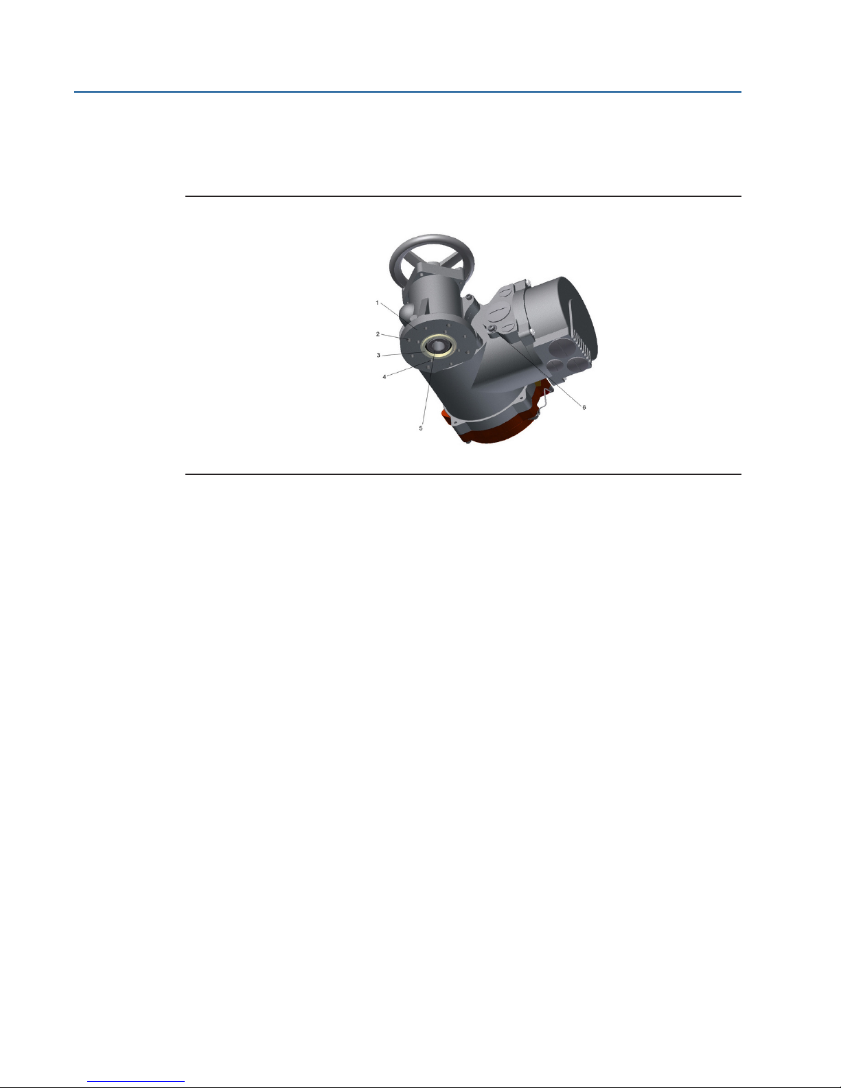
Figure 1 Bettis RTS FQ Fail-Safe Quarter-Turn Actuator
1

User Instructions
Part Number IOM – 87376-7 July 2016, Rev 1.0
Section 2: Functional Description of the RTS FQ
Fail-Safe Quarter-Turn Actuator
In normal operation, the actuator is operated by a PM motor (1) via a worm gear stage (2) and a
planetary gear train (3). The motor drives the spindle nut of a ball screw (4). The sun gear shaft
of the planetary gear train is xed in place by an operating current brake (5).
The ball screw converts the rotational movement of the gear unit into linear motion, which, on
the other hand, charges the spring assembly (7), which acts as an energy storage device. On the
other hand, a rack and pinion gear (6) converts the linear motion into the 90o output motion to
move the tting shaft (9).
There are no engaging or disengaging elements between the motor. The energy storage device
and the tting shaft in the actuator. All the gear unit components are permanently engaged.
While moving against the fail-safe direction, the electric motor has to move both the tting and
the energy storage device (disk spring assembly) for the fail-safe stroke.
If the supply for the operating current brake is interrupted by a power failure, or intentionally
triggers a fail-safe stroke, the actuator will no longer hold position, and the energy stored in the
disk spring assembly will be converted into kinetic energy so as to move the actuator and thus
the tting to the fail-safe position. In this situation, the entire gear chain for the actuator with
the exception of the worm gear stage will be moved until the adjustable mechanical end stop
(8) is reached or, if applicable, be stopped for the tting.
Owing to this operating principle, neither an initializing stroke nor resetting of the drive
is required after a fail-safe stroke. As soon as the power supply is restored, the actuator is
immediately ready for operation.
Figure 2 Cut-out of the RTS FQ Fail-Safe Quarter-Turn Actuator
2

User Instructions
Part Number IOM – 87376-7 July 2016, Rev 1.
Parts Overview:
1. PM Motor
2. Worm Gear Stage
3. Planetary Gear Train
4. Ball Screw
5. Operating Current Brake
6. Rack and Pinion Gear
7. Spring Assembly
8. End Stop
9. Fitting Shaft
This compact fail-safe actuator can be built as a version for “fail-safe open” (counter clockwise
direction of rotation when looking at the tting shaft) or “fail-safe close” (clockwise direction
of rotation). It is even possible to subsequently change the fail-safe direction (separate manual
available). Some assembly work is required. Having this conversion performed at our factory is
recommended, however.
Figure 3 Fail-Safe Open Version
Figure 4 Fail-Safe Close Version
3

User Instructions
Part Number IOM – 87376-7 July 2016, Rev 1.0
Section 3: General Information
3.1 Safety Instructions
CAUTION: FOLLOW SAFETY INSTRUCTIONS
When operating electrical devices, certain parts are inevitably under dangerous voltage. Work
on the electrical systems or components may only be carried out by electricians or by
individuals who have been instructed how to do so, working under the guidance and
supervision of an electrician in accordance with electrotechnical regulations.
WARNING: ALWAYS REFER TO STANDARDS
When working in potentially explosive areas, refer to European Standards EN 60079-14
“Installing Electrical Systems in Explosion Endangered Areas” and EN 60079-17 “Inspection and
Maintenance of Electrical Installations in Explosion Endangered Areas”.
Working in potentially explosive areas is subject to special regulations (European Standard EN
60079-17), which must be complied with. Any additional national regulations must be heeded.
CAUTION: NO DANGER OF EXPLOSION IS CERTAIN
Work on the open actuator under voltage may only be done if it is certain that there is no
danger of explosion for the duration of the work.
3.2 Direction of Rotation
CAUTION: OBSERVE DIRECTION OF ROTATION
The standard direction of rotation for the actuator is:
• Clockwise = The actuator runs counter to the fail-safe direction
• Counter clockwise = The actuator runs in the fail-safe direction
Which direction, opening or closing of the tting causes, depends on:
• The fail-safe direction of the actuator
• The closing direction of the tting
All the information in this Operating Manual refers to the standard direction of rotation.
Section 4: Packaging, Transport and Storage
Depending on the order, actuators may be delivered packed or unpacked. Special packaging
requirements must be specied when ordering. Please use extreme care when removing or
4
repackaging equipment.

User Instructions
Part Number IOM – 87376-7 July 2016, Rev 1.
CAUTION: USE APPROPRIATE LIFTING EQUIPMENT
Use soft straps to hoist the equipment; do not attach straps to the handwheel. If the actuator is
mounted on a valve, attach the hoist to the valve and not to the actuator.
4.1 General
The connection compartment of RTS FQ Fail-Safe Quarter-Turn actuators contains 5g of factory
supplied silica gel.
CAUTION: REMOVE SILICA GEL
Please remove the silica gel before commissioning the actuator (see Section 16).
4.2 Storage
CAUTION: OBSERVE PROPER STORAGE
Please observe the following measures to avoid damage during the storage of actuators:
• Store actuators in well-ventilated, dry premises.
• Protect against oor dampness by storing actuators on wooden grating, pallets, mesh
boxes or shelves.
• Protect the actuators against dust and dirt with plastic foil.
• Actuators must be protected against mechanical damage.
• Storage temperature must be between -20oC to +40oC.
It is not necessary to open the controller of the actuator for servicing batteries or similar
operations.
4.3 Long-Term Storage
CAUTION: FOLLOW PROPER STORAGE
If you intend to store the actuator for over 6 months, follow additional instructions below:
• The silica gel in the connection compartment must be replaced after 6 months of
storage (from date of delivery).
• After replacing the silica gel, brush with glycerine the connection cover seal. Then,
carefully close again the connection compartment.
• Coat screw heads and bare spots with neutral grease or long-term corrosion protection.
• Renovate damaged paint work arising from transport, improper storage, or mechanical
inuences.
• Every 6 months, all measures and precautions for long term storage must be checked for
eectiveness and corrosion protection and silica gel renewed.
• Failure to follow the above instructions may lead to condensation which can damage to
the actuator.
5

User Instructions
Part Number IOM – 87376-7 July 2016, Rev 1.0
Section 5: Installation Instructions
Installation work of any kind for the actuator may only be performed by qualied personnel.
5.1 Mechanical Connection
Check:
• Whether the tting ange and actuator ange match-up.
• Whether the drilled hole matches up with the shaft.
• Whether there is sucient engagement of the tting shaft in the actuator hole.
Make sure the tting is in the same position as the actuator:
• For a “fail-safe opener” actuator, the tting has to be completely open.
• For a “fail-safe closer” actuator, the tting has to be completely closed.
In general, heed the following instructions:
• Clean the bare parts on the actuator coated with rust protectant.
• Clean the mounting surface for the tting thoroughly.
• Lightly grease the tting shaft.
• Set the actuator in place.
• Make sure of centered positioning and that the contact surface of the ange is full.
• Fasten the actuator with suitable bolts:
— Minimum strength grade: 8.8 or A2-70
— Ensure sucient thread engagement (min. 1xd)
Screws that are too long may go against the thread root, creating the risk of the actuator moving
radially in relation to the tting. This may lead to the bolts shearing o.
CAUTION: USE SUITABLE BOLTS
Unsuitable bolts may result in the actuator falling o.
• Tighten bolts to the correct torque, alternating between bolts on opposite sides.
Table 1. Torque Thread Table (1)
Thread
M6 11 8
M8 25 18
M10 51 36
M12 87 61
M16 214 150
M20 431 294
M30 1489 564
Tightening Torque [Nm] for Bolts with Strength Grade
8.8 A2-70/A4-70
See Section 15.2.
6

User Instructions
Part Number IOM – 87376-7 July 2016, Rev 1.
Section 6: Commissioning
It is assumed that the actuator has been installed and electrically connected correctly. (See
Section 5).
NOTE:
Remove silica gel from the alarm cover.
6.1 General Information
NOTE:
When commissioning and each time after dismounting the actuator, the electrical end
positions have to be reset (see Section 16.4).
6.2 Manual Operation
There is no way to operate this actuator design manually.
6.3 Setting the Mechanical End Stop
The RTS FQ Fail-Safe Quarter-Turn actuator only has one limited mechanical end stop that limits
the travel at the fail-safe end position. The end stop is at the end of the spring cup.
Depending on the size of the actuator, the end stop can be combined with a hydraulic damper.
Figure 5 Mechanical End Stop (1)
Parts Overview:
1. Lock Nut
2. End Stop
7

User Instructions
Part Number IOM – 87376-7 July 2016, Rev 1.0
Figure 6 Mechanical End Stop (2)
Parts Overview:
1. Lock Nut
2. End Stop
Figure 7 Mechanical End Stop (3)
Parts Overview:
1. Lock Nut
2. End Stop (hex SW70mm)
3. Hydraulic Damper
4. Damper Adjusting Screw
5. Cover
To adjust the end stop, rst undo the locknuts. To lengthen the stroke by means of the end
stop, unscrew the end stop out of the cover ange.
NOTE:
Upon delivery, the end stop is set to the maximum possible stroke. Further unscrewing causes
no further extension of stroke; the end stop becomes ineective.
Check:
8

User Instructions
Part Number IOM – 87376-7 July 2016, Rev 1.
• In fail-safe operation, let the actuator run against the stop.
• Despite the locknut being undone, it must not be possible to screw the end stop
further into the cover ange.
NOTE:
If the stroke is to be shortened by means of the end stop, the actuator must not be in the
fail-safe position. Before adjusting, it is necessary to move the actuator electrically at least 10%
away from the end position.
After undoing the locknut, screw the end stop into the cover ange, and check the adjustment
of the end stop by triggering a fail-safe stroke.
In electrical operation, it is not permissible for the mechanical end stop to be run into. After
adjusting the mechanical end stop, check the setting of the travel end position and correct it if
necessary. After completing the adjustment work, x the locknuts back in place.
6.4 Adjusting the Hydraulic Damper (If applicable)
The hydraulic damper allows the velocity prole to be adjusted in small degrees in fail-safe
operation. The hydraulic damper is preset and it is not recommended that the setting be
changed. Too weak adjustment of the damper may cause peak forces when the end stop is
reached, whereas too strong adjustment may cause problems during electrical operation in the
fail-safe direction. If, in spite of this, changes are required in the damper setting, proceed with
caution and only make small changes in combination with test runs.
Procedure:
• Remove the damper cover.
• There is a graduated dial with an adjusting screw on the end side of the damper.
• Adjusting to smaller numerical values causes weaker damping and an increase in the
shifting speed.
• Only adjust by half number values and repeat test runs.
• After completing the adjustment work, put the cover back on and make sure the
position of the damper to the housing does not get changed during the adjustment
work.
6.5 Final Step
Following commissioning, check for proper sealing the covers to be closed and cable inlets
(see Section 13.4). Check actuator for paint damage (by transport or installation) and repair if
necessary.
Section 7: Maintenance
All maintenance work may only be performed with the actuator disconnected from the power
supply. Due to this requirement, the actuator has to be in the fail-safe position. If this is not the
case, it may be because of a fault in the tting (stuck tting shaft).
9

User Instructions
Part Number IOM – 87376-7 July 2016, Rev 1.0
CAUTION: REFRAIN CAUSING STRESS IN ACTUATOR
The actuator has a prestressed disk spring assembly. When undoing the ange mounting bolts,
the spring force against the tting can cause the actuator to turn abruptly or come loose from
the tting. Adequate safety measures must be taken.
Any powering up must be ruled out during maintenance. Work on the electrical systems or
components may only be carried out by electricians or by individuals who have been instructed
how to do so. Work under the guidance and supervision of an electrician in accordance with
electrotechnical regulations.
After completing their commissioning, the actuators are ready for use. The actuator is lled
with oil, as standard, when shipped.
Routine checks:
• Be mindful of increased running noises. In cases of long down times, operate the
actuator at least every three months.
• Check the fail-safe function (check the operating time and smoothness of running
in fail-safe operation). Lengthening in the running time may also be caused by an
increased torque requirement for the tting after long downtimes.
CAUTION: ALWAYS REFER TO INSTRUCTIONS
The actuator has a prestressed disk spring assembly. Improper dismounting may lead to both
damage to the actuator as well as serious injuries. If maintenance work is needed requiring the
actuator to be dismounted, contact Emerson regarding detailed instructions and/or any special
purpose tools for relaxing the spring assembly.
The actuators are designed for any mounting position (see Section 3.4), which is why there is
neither a lling level indicator nor a drain plug on the main casing.
Depending on the stress actuator is subjected to, do the following approximately every 10,000
to 20,000 hours (about 5 years; see Section 10):
• Oil change
• Replace seals
• Check all the roller bearings and the worm gear assembly and replace if necessary.
Take the types of oils and greases to be used from our Lubricant Recommendation Table (see
Section 9).
Section 8: Lubricant Recommendation and
Requirements
8.1 Main Casing
Gear oil: DIN 51 517 - CLP - HC
Fully synthetic high performance industrial gear oils based on poly-alpha-olens (PAO)
Temperature: -25 to +60oC
10

User Instructions
Part Number IOM – 87376-7 July 2016, Rev 1.
Viscosity grade: 320 ISO VG
Lubricant requirements: 0.25 Lt
8.2 90o Gear Unit and Spindle Actuator
Lubricating grease: DIN 51862 - G1- G
Water repellent, Al-soap-based complex grease with high resistance to acids and alkalis
Temperature: -40 to +85oC
Worked penetration of 0.1mm: by 265
Dropping point: approx. 260o C
NLGI grade: 1
Acid-free, non or only slightly water reactive
8.3 Basic Lubricant Service Interval
CAUTION: CONSIDER REDUCTION FACTORS
The service interval for RTS FQ Fail-Safe Quarter-Turn actuators is ten years from the shipping
date. However, the functionality and service life of the lubricants depends on the operating
conditions. Reduction factors have to be taken into consideration if applicable.
Table 2. Lubrication Utilization (1)
Operating
Condition(s)
Duty Cycle (DC) (Total motor running time)
Extremely high DC Over 1,250 hours/year 0.5
High DC Over 500 hours/year 0.7
Extremely low DC Less than 0.5 hours/year 0.8
Ambient temperature (permanent or longterm)
Extremely changeable Between -10oC and +50oC 0.5
Extremely high Over +50oC 0.7
Extremely low Below -25oC 0.9
Output speed (on main shaft of actuator)
High speed Over 80 rpm 0.8
Degree of utilization (based on nominal capacity)
Very high Over 90% 0.8
High Between 80 to 90% 0.9
Example of application:
Denition
Reduction Factor
(Multiplier)
Extremely low DC + extremely low ambient temperature + high speed + 87% degree of
utilization: 0.8 x 0.9 x 0.8 x 0.9 = 0.51
Reduction factor lubricant maintenance interval: 10 years x 0.51= 5.1 years (62 months)
NOTE:
A maintenance interval calculated this way does not apply to the maintenance of output type A
11

User Instructions
Part Number IOM – 87376-7 July 2016, Rev 1.0
(threaded bush) or to the maintenance of linear actuator or spindle actuator units. These have
to be relubricated at regular intervals (at least every six months) at the grease nipples (Section
26.2).
When servicing our actuators, the old lubricant must always be removed and replaced with
new lubricant. No mixing of dierent makes of lubricant is allowed.
The quantities needed for lubricant servicing are set out in Section 26.
Section 9: Training
CAUTION: CONTACT FOR SUPPORT
If you experience any problems during installation or in doing the adjustment work on site,
please contact Emerson at phone +1 281 477 4100 to avoid any possible faulty operation or
damage to the actuator. Emerson recommends only using qualied personnel to do the installation. Please contact Emerson to request product training.
Section 10: Operating Manual - Introduction
These operating instructions apply to RTS FQ Fail-Safe Quarter-Turn actuators.
The scope of application covers the operation of industrial valves, e.g., globe valves, gate
valves, buttery valves and ball valves. For other applications please consult with Emerson.
Emerson shall not be liable for the improper or incorrect use of and therefore possible damage
arising thereof. The risk shall be borne solely by the user.
Use of the actuator entails the streict observance of these operating instructions.
CAUTION: OBSERVE HAZARDOUS VOLTAGE LEVEL
When operating electrical equipment, certain parts inevitably carry hazardous voltage levels.
Work on the electrical system or equipment must be carried out only in accordance with
electrical regulations by a qualied electrician himself or by specially instructed personnel
under the control and supervision of a qualied electrician.
Maintenance instructions must be observed as otherwise the safe operation of the actuator
cannot be guaranteed. Failure to follow the warning information may result in serious bodily
injury or property damage. Qualied personnel must be thoroughly familiar with all warnings
contained in this operating manual. Proper transport, storage, installation, assembly and
12

User Instructions
Part Number IOM – 87376-7 July 2016, Rev 1.
careful commissioning are essential to proper and safe operation.
WARNING: ALWAYS REFER TO STANDARDS
When working in potentially explosive areas, observe the European Standards EN 60079-14
"Electrical Installations in Hazardous Areas" and EN 60079-17 "Inspection and Maintenance of
Electrical Installations in Hazardous Areas". Maintenance work on open actuators may only be
conducted if these are deenergized. Reconnection during maintenance is strictly prohibited.
Section 11: General
The RTS FQ Fail-Safe Quarter-Turn Series are compact, rotary actuators with integrated
controller for valve operation. The integral multi-turn sensor allows setting the travel up to 105
revolutions without opening the housing.
11.1 Overview
Figure 8 RTS Control Unit
Parts Overview:
1. Handwheel
2. Control Unit (Operating Unit)
3. Connection Compartment
4. Gear Component
11.2 Serial Number and Nameplate
Each actuator has a serial number. The serial number is a 10-digit number that begins with the
year and that can be read from the nameplate (see Figure 9) of the actuator (the nameplate is
located next to the handwheel – see Figure 10). Using this serial number, Emerson can uniquely
identify the actuator (type, size, design, options, technical data and test report).
Figure 9 Nameplate
13

User Instructions
Part Number IOM – 87376-7 July 2016, Rev 1.0
Figure 10 Name Plate Position
11.3 Operating Mode
RTS FQ Fail-Safe Quarter-Turn actuators are suitable for open-loop control (S2 operating mode
- on/o duty) and closed- loop control (S4 operating mode - modulating duty) according to EN
60034-1.
11.4 Protection Class
RTS FQ Fail-Safe Quarter-Turn actuators come by default with IP67 (EN 50629) protection.
CAUTION:PROTECTION CLASS AND CABLE GLANDS
The protection class specied on the nameplate is only eective when cable glands also provide
the required protection class. The cover of the connection compartment is carefully screwed
and the mounting position (see Section 13.5) is observed.
14

User Instructions
Part Number IOM – 87376-7 July 2016, Rev 1.
We recommend metallic screwed cable glands with a metrical thread. Furthermore, cable inlets
not be needed must be closed with screw plugs. On explosionproof actuators cable glands with
protection class EExe according EN 60079-7 must be used. After removing covers for assembly
purposes or adjustment work, take special care upon reassembly so that seals are not damaged
and remain properly fastened. Improper assembly may lead to water entrances and to failures
of the actuator.
NOTE:
The cover of the control unit - the operating unit (see Figure 8) must not be opened.
Allow a certain sag in the connector cables before reaching the screwed cable glands so that
water can drip o from the connector cables without running to the screwed cable glands. As a
result, forces acting on the screwed cable glands are also reduced (see Section 13.5).
11.5 Mounting Position
In principle, the installation position is irrelevant. However, based on practical experience, it is
advisable to consider the following for outdoors use or in splash zones:
• Mount actuators with cable inlet facing downwards.
• Ensure that sucient cable slack is available.
11.6 Direction of Rotation
Unless specically ordered otherwise, the standard direction is (see Figure 12 and Figure 13):
• Right turning (clockwise) = CLOSED
• Left turning (counter clockwise) = OPEN
Clockwise rotation of the actuator is given when the output shaft turns counterclockwise when
looking on the output shaft.
Figure 11 Clockwise = Close
15

User Instructions
Part Number IOM – 87376-7 July 2016, Rev 1.0
Figure 12 Counterclockwise = Open
CAUTION: 0BSERVE DIRECTION OF ROTATION
All specications in this operating manual refer to the standard direction of rotation.
11.7 Protection Devices
11.7.1 Torque
RTS CM Compact Series actuators provide a electronic torque monitoring. Over torque can be
modied in the menu of the controller for each direction separately. By default, over torque is
set to the ordered value. If no torque was specied with the order, the actuator is supplied from
the factory with the maximum congurable torque.
For more information, see Section 18.2.
11.7.2 Motor Temperature
All RTS CM Compact Series actuators are normally equipped with motor winding temperature
sensors, which protect the motor against excessive winding temperature. The display will show
the corresponding error upon exceeding the permissible motor temperature (see Section
23.1).
11.7.3 Input Fuse and Thermal Fuse
The frequency inverter is protected by an input fuse and the explosionproof version also has a
thermal fuse. If one of these fuses releases, a serious defect occurs and the frequency inverter
will be disconnected permanently from the power supply. Then the frequency inverter must be
changed.
11.8 Ambient Temperature
Unless otherwise specied upon ordering, the following operating temperatures apply:
• On/o duty (open-loop control): -40oC to +60oC
• Modulating duty (closed-loop control): -40oC to +60 oC
16

User Instructions
Part Number IOM – 87376-7 July 2016, Rev 1.
• Explosion Proof version: -20oC to +40oC (according to EN60079-0)
• Explosion Proof version with extended temperature range: -40oC to +60oC
CAUTION: OBSERVE OPERATION TEMPERATURE
The maximum operating temperature can also depend on further order specic components.
Please refer to the technical data sheets to conrm the as-delivered product specications.
11.9 Delivery Condition of the Actuators
For each actuator, an inspection report is generated upon nal inspection. In particular, this
comprises a full visual inspection, calibration of the torque measurement in connection with
an extensive run examination and a functional test of the micro controllers. These inspections
are conducted and documented according to the quality system and can be made available
if necessary. The basic setting of the end position must be performed after assembly on the
actuator.
CAUTION: OBSERVE COMMISSIONING INSTRUCTIONS
Commissioning instructions (see Section 16) must be strictly observed. During assembly of the
supplied valves at the factory, end postions are set and documented by attaching a label (see
Figure 14). During commissioning at the plant, these settings must be veried.
11.10 Information Tag
Each actuator is provided with a safety ag containing key information, which is attached to the
handwheel after nal inspection. This safety tag also shows the internal commission registration
number (see Figure 15).
Figure 13 Safety Tag
17
User Instructions
Part Number IOM – 87376-7 July 2016, Rev 1.0
Section 12: Installation Instructions
Figure 14 RTS FQ Fail-Safe Quarter-Turn Installation
Parts Overview:
1. Mounting Flange
2. Bore Pattern G0/F10
3. Centering Ring
4. Bore Pattern F07
5. Shaft Connection
6. Ground Connection
Installation work on any kind of actuators may only be performed by qualied personnel.
12.1 Mechanical Connection
See Figure 16.
Check whether the valve ange, actuator ange and valve shaft coincide with the shaft connector
of the actuator. For output type A (threaded bushing with bore), check whether the thread of the
valve matches the thread of the actuator.
In general, proceed as follows:
• Clean the bare parts of the actuator uncoated with corrosion protection.
• Thoroughly clean the screw mounting surfaces of the valve.
• In the actuator, lubricate appropriately the output shaft and the valve of the driven shaft.
• In the A version, ensure that the valve bushing is amply lubricated.
• Attach the actuator to the valve or gearbox.
• Tighten fastening screws (torque according to table below).
• By means of the handwheel, check the ease of movement of the actuator-valve
connection.
18

User Instructions
Part Number IOM – 87376-7 July 2016, Rev 1.
Table 3. Torque Thread Table (2)
Thread
M6 11 8
M8 25 18
M10 51 36
M12 87 61
M16 214 150
M20 431 294
M30 1489 564
8.8 A2-70/A4-70
For output type A (unbored threaded bushing), you must suciently lubricate both needle
bearings in the output form after processing and cleaning the spindle nut. For this purpose, use
the optional RTS FQ Fail-Safe Quarter-Turn Series grease lubricant or a grease lubricant according
to our
recommendation (see Section 26.2, page 84).
12.2 Mounting Position of the Operating Unit
Figure 15 RTS FQ Fail-Safe Quarter-Turn Control System
Tightening Torque [Nm] for Bolts with Strength Grade
• Disconnect the actuator and control system from the power supply.
• To prevent damage to the electronic components, both the control system and the
person have to be grounded.
• Undo the bolts for the interface surface and carefully remove the service cover.
• Turn service cover to new position and put back on.
— Ensure correct position of the O-ring.
— Turn service cover by maximum of 180o.
— Put service cover on carefully so that no cables get wedged in.
• The bolts evenly in a crosswise sequence.
NOTE:
Maximum torque of 5 Nm.
19

User Instructions
Part Number IOM – 87376-7 July 2016, Rev 1.0
12.3 Electrical Connection
Electrical connections may only be carried out by qualied personnel. Please observe all
relevant national security requirements, guidelines and regulations. The equipment should be
deenergized before working on electrical connections. Furthermore, conrm the absence of
electrostatic discharges during the connection. First of all, connect the ground screw.
The line and short circuit protection must be done on the system side. The ability to unlock the
actuator is to be provided for maintenance purposes. For the dimensioning, the rated current is
to be used (see Technical Data).
Check whether the power supply (voltage, frequency) is consistent with the connection data (see
nameplate - Figure 9). The connection of electrical wiring must follow the circuit diagram. This
can be found in the appendix of the documentation. The circuit diagram can be ordered from
Emerson by specifying the serial number. When using options, such as a Probus connection, the
relevant guidelines must be followed.
12.3.1 Power Supply Connection
RTS CM Compact Series actuators feature an integrated motor controller, i.e., it only requires a
connection to the power supply. By non-explosionproof actuators the wiring uses a connector
independent from control signals (see Figure 18).
Figure 16 Power Supply Connections
Parts Overview:
1. Metric Screw M32x1.5
2. M40x1.5
3. M25x1.5
4. Plug Insert Han6E (for power supply)
5. Plug Insert Han24E (for control cables)
6. Connector for Options
7. Connector Plate
8. Connecting Housing
Explosion proof actuators or on special request the connection will be made via terminals (see
20

User Instructions
Part Number IOM – 87376-7 July 2016, Rev 1.
Figure 19).
Figure 17 Terminal Box
Parts Overview:
1. Metric Screw M40x1.5
2. 2xM20x1.5
3. Terminals for the Control Signals
4. Terminals for the Power Supply
5. Terminal for Ground Connection
6. Outside Ground Connection
If, during outdoor installation, commissioning is not carried out immediately after electrical
connection. The power supply must be connected at a minimum to achieve a heating eect. In
this case, the silica gel may remain in the connection compartment until commissioning.
CAUTION: OBSERVE CORRECT PROCEDURE
See Section 14.3.
Section 13: Setting Limits
Before commissioning, please ensure the actuator is correctly assembled and electrically
connected. (see Section 15).
CAUTION: REMOVE SILICA GEL
Remove silica gel from the connection compartment.
13.1 General
CAUTION: ELECTRICAL END POSITION MUST BE RESET
21

User Instructions
Part Number IOM – 87376-7 July 2016, Rev 1.0
During commissioning and after every disassembly of the actuator, the electric end positions
(see Section 16.4) must be reset.
13.2 Manual Operation
The use of a dierential gearbox in the handwheel assembly makes mechanical switching
unnecessary during manual operation.
CAUTION: MANUAL OPERATION IS PROHIBITED
Manual operation with mechanical or electromechanical equipment (such as lever, drilling
machine, etc.) is not allowed, as this may damage the product.
13.3 Mechanical Default Settings and Preparation
The use of multi-turn sensors makes mechanical settings unnecessary.
CAUTION: ALWAYS CHECK TORQUE SETTINGS
Before the motorized operation of the valve, it is essential to check and eventually adjust torque
settings.
13.4 End Limit Setting
A detailed description of the operation of the RTS FQ Fail-Safe Quarter-Turn actuator controller
can be found in Section 17.3.
13.4.1 End Limit OPEN
Set the selector switch and control switch to the center position.
Figure 18 Selector/Control Switch
Parts Overview:
1. Selector Switch (red)
2. Control Switch (black)
22

User Instructions
Part Number IOM – 87376-7 July 2016, Rev 1.
Scroll through the menu with the control switch. Move the control switch towards the rst
menu item P1.1 End limit – Open.
Figure 19 Control Switch (First Menu Item)
Figure 20 Display (1)
Afterwards, ip up the selector switch slightly and let it snap back to its neutral position .
Figure 21 Selector Switch in Neutral Position (1)
Figure 22 Selector Switch Flipped Up (1)
23

User Instructions
Part Number IOM – 87376-7 July 2016, Rev 1.0
Figure 23 Selector Switch in Neutral Position (2)
This changes the bottom line of the display from EDIT? to SAVE?.
Figure 24 Display (2)
24

User Instructions
Part Number IOM – 87376-7 July 2016, Rev 1.
Figure 25 Display (3)
Then, push down the selector switch until it snaps into place. In doing so, the bottom right now
on the display will show "TEACHIN" Х.
CAUTION: USE APPROPRIATE SWITCH
Once the display shows "TEACHIN", use the operating switch (black switch) to start the
motorized operation of the actuator. In this mode, no travel-dependent switch o occurs in the
end position.
CAUTION: MAX. TORQUE MUST BE PARAMETERISED
Please note that during motor operation, only torque monitoring remains active as travel
adjustment will happen subsequently. Therefore, please check beforehand whether the
maximum torque has been already parameterised.
Absolute and relative values on the display will change continuously along with position
changes.
25

User Instructions
Part Number IOM – 87376-7 July 2016, Rev 1.0
Figure 26 Selector Switch Flipped Down
Figure 27 Display (4)
Manually move the actuator with the handwheel (see Section 13.1 or Section 13.6) or by motor
via the operating switch (black button) to the end position OPEN of the valve.
• Absolute value: Absolute value of the position feedback.
• Relative value: The value to the other end position.
Figure 28 Display (5)
26

User Instructions
Part Number IOM – 87376-7 July 2016, Rev 1.
Display Overview:
1. Absolute value
2. Relative Value
When the desired end position OPEN of the valve is reached, move the selector switch back to
the middle position. Thus, the line "TEACHIN" disappears.
Figure 29 Selector Switch in Neutral Position (4)
Figure 30 Display (6)
In order to conrm the end position (save), slightly ip up the selector switch and let it snap
back to its neutral position .
Figure 31 Selector Switch in Neutral Position (5)
27

User Instructions
Part Number IOM – 87376-7 July 2016, Rev 1.0
Figure 32 Selector Switch Flipped Up (2)
Figure 33 Selector Switch in Neutral Position (6)
28

User Instructions
Part Number IOM – 87376-7 July 2016, Rev 1.
This changes the bottom line of the display for "SAVE?" to "EDIT?" and the end position is stored.
Figure 34 Display (7)
Figure 35 Display (8)
13.4.2 End Limit CLOSE
Use menu item P1.2 End limit - End limit CLOSE as for End limit OPEN.
Section 14: Adjustment of Fail-Safe Speed
Mounting of Linear Fail-Safe Actuator
RTS FQ Series ctuators move the stem of valve to the fail-safe position in case of fail-safe event.
In general stem of actuator is at fail-safe position at delivery!
Depending on valve has to be closed or opened by force (sealing force is required in fail- safe
position) or by travel (actuator shall stop before touching the seat), mounting procedure has to
be done dierent:
Mounting procedure for valve without required sealing force:
29

User Instructions
Part Number IOM – 87376-7 July 2016, Rev 1.0
• Connect mounting kit to valve and x according valve producer specication
• Be sure stem of valve is exact in desired fail-safe end position
• Be sure stem of actuator is in fail-safe position. Actuator must not be electrically
connected! Hand wheel must not be engaged. (if applicable, refer to 6.2 manual operation)!
• Mount actuator to mounting kit and x with 4 screws
• Check distance between end of stem of actuator and end of stem of valve. Aallowed
range of distance is 2 – 25mm
• Connect both stems with coupling and note symmetrical engagement of both threads!
• Fix coupling with four screws and note both halves of coupling have to be parallel after
tightening the screws
Mounting procedure for valve with required sealing force:
30

User Instructions
Part Number IOM – 87376-7 July 2016, Rev 1.
• Connect mounting kit to valve and x according valve producer specication
• Be sure stem of valve is exact in desired fail-safe end position
• Stem of actuator has to be moved 2 – 5 mm away from fail-safe position by using hand
wheel (if applicable, refer to 6.2 manual operation)!
If actuator is not equipped with hand wheel switch to alternative procedure:
• Mount actuator to mounting kit and x with 4 screws
• Check distance between end of stem of actuator and end of stem of valve:
allowed range of distance is 2 - 25mm
• Connect both stems with coupling and note symmetrical engagement of both threads!
• Fix coupling with for screws and note both halves of coupling have to be parallel after
tightening the screws
Alternative procedure for valve with required sealing force:
• Connect mounting kit to valve and x according valve producer specication
• Be sure stem of valve is exact in desired fail-safe end position
• Loosen hexagonal nuts of mounting kit and generate a gap of 3 - 5 mm between ange
and pillar
• Mount actuator to mounting kit and x with 4 screws
• Check distance between end of stem of actuator and end of stem of valve. Allowed
range of distance is 2 - 25mm
• Connect both stems with coupling and note symmetrical engagement of both threads!
• Fix coupling with for screws and note both halves of coupling have to be parallel after
tightening the screws
• Finally retighten hexagonal nuts symmetrical until gap disappears
Attention: actuator must not be electrically connected! Hand wheel must not be engaged
(if applicable, refer to 6.2 Manual Operation)!
Section 15: Control Unit
The controller is intended to monitor and control the actuator and provides the interface
between the operator, the control system and the actuator.
15.1 Operating Unit
Operation relies on two switches: the control switch and a padlock-protected selector switch.
Information visualization is provided by 4 integrated indicator lights as well as the graphic
display. For better visibility, switch symbols ( , , , ) are on the cover.
31

User Instructions
Part Number IOM – 87376-7 July 2016, Rev 1.0
Figure 36 Selector/Control Switch Operating Unit
Parts Overview:
1. Selector Switch
2. Control Switch
3. Graphic Display
4. LED Display
The controller switches serve on the one hand for electric motor operation of the actuator and,
on the other hand, to congure and view various menu items.
The controller cover may be wiped clean with a damp cloth. The mounting position of the
control unit can be turned in 90o steps (see Section 15.2).
15.2 Display Elements
15.2.1 Graphic Display
The graphic display used in the controller allows text display in dierent languages.
Figure 37 Display (9)
32
During operation, the displays shows the position of the actuator as a percentage, operation
mode and status. When using the option identication, a customer-specic label is shown at
the bottom of the display (e.g., PPS Number).

User Instructions
Part Number IOM – 87376-7 July 2016, Rev 1.
15.3 Operation
The actuator is operated via the switches located on the controller (selection and control
switch). All actuator settings can be entered with these switches. Furthermore, conguration is
also possible via the IR interface or the Bluetooth Interface (see Section 20). Flip the switch up
or down to regulate the parameter menu scrolling speed.
Figure 40 Neutral Position
Figure 41 Slight Switch Flip (it will move to the next parameter)
LED L1 and L2 can be changed by parameter P1.7 - see Section 18.1.
33

User Instructions
Part Number IOM – 87376-7 July 2016, Rev 1.0
Figure 42 Halfway Switch Flip (it will jump to the next parameter category)
Figure 43 Full Switch Flip (it will jump to the end of the menu)
15.3.1 Operation Mode
Use the selector switch (red) to determine the various operating states of the actuator. In each
of these positions, it is possible to block the switch by means of a padlock and thus protect the
actuator against unauthorized access.
The selector switch has the following positions:
Table 5. Operating Mode Table
OFF
Local
Remote
Besides dening the operational status, the selector switch is used in conguration mode to
conrm or cancel parameter inputs.
34
The actuator can be neither operated via the remote
control nor via the control switches of the controller.
It is possible to operate the actuator by motor via the control
switch. Control via the remote inputs may be possible with
appropriate conguration (superimposed control commands,
emergency commands).
The actuator is ready to process control commands via input
signals. The control switch for the motor operation of the
actuator is not enabled.

User Instructions
Part Number IOM – 87376-7 July 2016, Rev 1.
Depending on the selector switch position, the control switch performs dierent functions:
Table 6. Selector Switch Position Table
The control switch is used to scroll up or down the menu
according to internal symbolism. From the neutral position
Selector switch in the
OFF position:
towards you reach the status and history data areas.
Towards the symbols you reach the parameter menu. Here,
the selection switch either conrms or rejects the
current input according to associated symbolism.
Selector switch in the
REMOTE position :
The control switch gives you access to status, history data and
parameter area.
With the control switch, the actuator can be operated by
motor. You may also operate the actuator in inching and
Selector switch in the
LOCAL position :
self-hold mode. Switches are spring-loaded to snap back
automatically into their neutral position. (To conrm a control
command, the control switch must be pushed all the way into
its mechanical locking position.)
15.3.2 Conguration
In principle, all parameters are shown as numbers in the corresponding parameter point. From
the actuator menu, use the control switch to access dierent menu points. The lower left
corner of the display shows the "EDIT?" option.
Figure 44 Display (11)
Conrm the selector switch with a slight ip towards , (see Figure 33 to Figure 35) to change
the selected parameter. To conrm this input readiness, the display changes from "EDIT?" to
"SAVE?".
35

User Instructions
Part Number IOM – 87376-7 July 2016, Rev 1.0
Figure 45 Display (12)
Use the control switch towards to the characters to change the parameter or (see Figure
42 to Figure 45). After reaching the desired parameter value, conrm the value with the
selector switch again, ip it slightly towards , (see Figure 33 to Figure 35).
15.3.3 Conguration Example
By way of example, we will change parameter P20.6 (wireless) from 0 (wireless o) to 2
(Bluetooth communication on). Thus, the Bluetooth connection is activated for a short time
and then deactivated again automatically. The operating and control switch must be in the
neutral position.
Figure 46 Selector/Control Switch (2)
Parts Overview:
1. Selector Switch (red)
2. Control Switch (black)
Now, move the control switch down towards until the menu item P20.6 Miscellaneous Wireless
is displayed.
Figure 47 Control Switch Flipped Down
36

User Instructions
Part Number IOM – 87376-7 July 2016, Rev 1.
Figure 48 Display (13)
Afterwards, ip up slightly the selector switch towards and let it snap back to its neutral
position.
Figure 49 Selector Switch in Neutral Position (7)
37

User Instructions
Part Number IOM – 87376-7 July 2016, Rev 1.0
Figure 50 Selector Switch Flipped Up (3)
Figure 51 Selector Switch in Neutral Position (8)
38
This changes the bottom line of the display from "EDIT?" to "SAVE?".
Figure 52 Display (14)

User Instructions
Part Number IOM – 87376-7 July 2016, Rev 1.
Figure 53 Display (15)
Thereafter, ip up the control switch toward to change the value from 0 (o) to 2 (Bluetooth).
Figure 54 Control Switch Flipped Up
Figure 55 Display (16)
39

User Instructions
Part Number IOM – 87376-7 July 2016, Rev 1.0
If the value changes to 1, conrm the selection by ipping halfway up the selector switch
towards and letting it snap back to its neutral position (see Figure 51 to Figure 53).
Figure 56 Selector Switch Flipped Halfway Up
Figure 57 Display (17)
This changes the bottom line of the display from "SAVE?" to "EDIT?" and the parameter is stored.
15.3.4 "TEACHIN"
Furthermore, certain parameters (end positions, intermediate positions) can be set using
"TEACHIN". Thus, their conguration is greatly simplied.
After selecting the appropriate menu item (for example: End position) and changhing the input
type from "EDIT?" to "SAVE?", move the selector switch (red) to manual mode and lock it into
place. As you do so, the display will show the message "TEACHIN" and the current position value
will be applied continuously to the parameter value. In this mode, further to manual operation
by hand wheel, the actuator can be motor-driven with the control switch to the desired position
(see Section 16.4.1, Figure 29).
40

User Instructions
Part Number IOM – 87376-7 July 2016, Rev 1.
Figure 58 Display (18)
CAUTION: MAX. TORQUE MUST BE ALREADY SET
Please note that, during motor operation, only torque monitoring remains active, as travel
adjustment will happen subsequently. Therefore, please check beforehand whether the
maximum torque has been already set.
After reaching the desired, to-be-dened position, move the selector switch back to the neutral
position. Finally, the parameter value must still be saved by ipping the selector switch halfway
up and letting it snap back to the neutral position (see Figure 51 to Figure 53).
Section 16: Parameter Menu
For each parameter group, you can nd a description tabular overview of the menu items and
possible congurations. The parameter list below also includes all possible options per menu
item. Please note that some of the menu items listed and described may not be delivered with
your conguration.
16.1 Parameter Group: End Limit
These parameters are used to congure the end position and switch o behavior of the
actuator. In this regards, it is important to ensure that the basic mechanical conguration
described in Section 16.4 has already been made.
NOTE:
Ensure that these parameters are set during commissioning before operating the actuator.
In addition, the settings in the "Torque" menu (see Section 18.2) must be compared with the
permissible values of the valve and corrected as appropriate.
41

User Instructions
Part Number IOM – 87376-7 July 2016, Rev 1.0
CAUTION: OBSERVE PROPER POSITIONING
Generally, 100% stands for fully open and 0% for fully closed. Please note that these values
cannot be changed.
Table 7. End Limit Table
Menu Item
P1.1 End limit Open
P1.2 End limit Close
P1.3 End limit
P1.4 End limit
P1.5 End limit
P1.6 End limit
P1.7 End limit LED function
P1.8 End limit
Sub Menu
Item
Switch o
Open
Switch o
Close
Closing
directing
Rotate sense
position
End limit
hysteresis
Poss. Setting Notes /Comments
TEACHIN;
0-100U1)
TEACHIN;
0-100U1)
by travel (0)
by torque (1)
by travel (0)
by torque (1)
right (0) Actuator is designed for clockwise = closing
left (1)
0
1
Close = green (0)
Close = red (1)
0,1 - 10,0%
The parameter value can be set using TEACHIN.
With a known travel, the second end position can be
entered after setting the rst end position.
The parameter value can be set using TEACHIN.
With a known travel, the second end position can be
entered after setting the rst end position.
The actuator uses end position signals to switch o and
report the end position.
The actuator signals the end position or stops the motor
only after reaching the specied torque with the proviso
that it has reached the end position. If the end position
signal is not reached, the actuator reports an error.
Reverse direction of rotation. Counterclockwise = closing.
The crossing of all signals and commands is performed by
the controller.
No function at RTS FQ Fail-Safe Quarter-Turn Series.
Denition of the LED colour of the CLOSED or OPEN end
position signalization.
Hysteresis range for end position signals, Example:
End position hysteresis 1% means, that the end position
OFF is reached when closing 0%, and will leave it when
opening only at 1%, i.e., a reclosing can only take place
after leaving this hysteresis.
CAUTION: OBSERVE LIMITS AND FACTORS OF GEAR
When installing the actuator on an gear or a thrust unit, please take into account the limits and
factors of the gear/thrust unit at parameterization.
When using end limit switch o by torque, the end position limit must be set before reaching
the torque limit. Accordingly, the actuator will only signal the nal end position if the
congured torque and the associated end position are reached. If the end position is not
reached, a torque error is reported (see Section 17.2.2).
42

User Instructions
Part Number IOM – 87376-7 July 2016, Rev 1.
16.2 Parameter Group: Torque
If no torque was specied with the order, the actuator is supplied from the factory with the
maximum congurable torque.
Table 8. Torque Table
Menu
Item
P2.1 Torque Open 8 - 32Nm
P2.2 Torque Close 8 - 32Nm2As P2.1 but in CLOSED direction
P2.3 Torque Torque limit 8 - 32Nm
P2.4 Torque Latching {O (0)} Unassigned in RTS FQ Fail-Safe Quarter-Turn Series
P2.5 Torque Boost Open {0%} Unassigned in RTS FQ Fail-Safe Quarter-Turn Series
P2.6 Torque Boost Close {0%} Unassigned in RTS FQ Fail-Safe Quarter-Turn Series
P2.7 Torque Hysteresis {0: 50%} Unassigned in RTS FQ Fail-Safe Quarter-Turn Series
Sub Menu
Item
Poss. Setting Notes/Comments
CAUTION: CONSIDER THE VALUE OF GEAR/THRUST
When installing the actuator on an additional gear, please take into account the
corresponding values of the gear/thrust unit as you enter the actuator parameters. To achieve
an eective output torque (including gear)/output power (including thrust unit) ratio, the
factor gear/thrust unit must be considered.
16.3 Parameter Group: Speed
Switch o torque in OPEN direction CAUTION:
2
The range can be restricted via the menu item P2.3
Torque to protect the valve, the transmission or the
thrust unit. This value limits the setting of the
2
parameters P2.1 and P2.2, and to prevent an
erroneous increase above the allowed value of these
two parameters.
Table 9. Speed Table
Menu
Item
P4.1 Speed Local Open 2.5 - 72.2min-2Output speed for local operation in direction OPEN
P4.2 Speed Local Close 2.5 - 72.2min-2As P4.1 but in direction CLOSE
P4.3 Speed
P4.4 Speed
P4.5 Speed
P4.6 Speed
Sub Menu
Item
Remote
Open
Remote
Close
Emergency
Open AUF
Emergency
Cl ose
Poss. Setting Notes/Comments
Output speed for remote operation in direction
2.5 - 72.2min
2.5 - 72.2min-2As P4.3 but in direction CLOSE
2.5 - 72.2min
2.5 - 72.2min-2As P4.5 but in direction CLOSE
-2
OPEN
Output speed for emergency operation in direction
-2
OPEN
43

User Instructions
Part Number IOM – 87376-7 July 2016, Rev 1.0
P4.7 Speed
P4.8 Speed Minimum 2.5 - 72.2min-2Minimum speed
Torque-
dependent
2.5 - 72.2min
Seal-tight speed. Speed at which the actuator runs
-2
near the end position at torque-dependent switch
o (see P1.3 and P1.4)
CAUTION: OBSERVE MAXIMUM SPEED
The maximum speed for the 24VDC actuator version is reduced to 20min−1.
16.4 Parameter Group: Ramp (Option)
The start ramp can be set separately for each operation mode. Thus, a 100% start ramp means
that the motor attains its maximum speed in about a second. Higher speeds (see Section
18.3) lead to shorter runtimes. If the ramp is set below 100%, the starting time increases in an
inversely proportional fashion.
Table 10. Ramp Table
Menu
Item
P5.1 Ramp Local 5 - 100% Start ramp for local operation
P5.2 Ramp Remote 5 - 100% Start ramp for remote operation
P5.3 Ramp Emergency 5 - 100% Start ramp for emergency operation
Sub Menu
Item
Poss. Setting Notes/Comments
16.5 Parameter Group: Control
Table 11. Control Table
Menu
Item
P6.2 Control Ready delay 0-10s
P6.5 Control 24V output
Sub Menu
Item
Poss. Setting Notes/Comments
0
1 24V auxiliary output is activated (Section 33.5).
16.6 Parameter Group: Password
The actuator control can be password-protected to prevent access at dierent levels. It is
possible to prevent entry by unauthorized personnel or to entirely lock motor operation.
Default password is set to "000" and thus deactivated. You can use both numbers and capital
letters in your password. After entering a password, password protection is activated. To
remove password protection, enter an empty password (000).
When accessing a password-protected parameter, the user is automatically prompted for
its introduction. Only after correctly entering the password, it is possible to change the
corresponding parameters.
Drop-out delay for the ready signal (Binary
outputs)
24V auxiliary output is deactivated (Section 33.5).
The function of the auxiliary input is still activated.
44

User Instructions
Part Number IOM – 87376-7 July 2016, Rev 1.
Table 12. Password Table
Menu
Item
P7.1 Password
P7.2 Password
Sub Menu
Item
Reading
PWD
Writing
PWD
Poss.
Setting
3- digit
3- digit
16.7 Parameter Group: Position
In addition to OPEN and CLOSED end positions, you may dene intermediate positions.
These can be used as feedback signals for the binary outputs or as target value for x position
approach.
CAUTION: OBSERVE PROPER POSITIONING
If you change the end positions, (see Section 18.1) intermediate positions are retained
percentage-wise, i.e., the absolute positions of the intermediate positions change.
Table 13. Position Table
Notes/Comments
Status display and history data are still viewable;
access to the parameter menu is locked until this
password is introduced. Parameter menu scrolling
is only enabled after entering the password.
Electric motor operation is unlocked.
Status display, history data and parameter menu
can be viewed. However, parameters become
read-only.
Menu
Item
P8.1 Position
P8.2 Position
P8.3 Position
P8.4 Position
P8.5 Position
P8.6 Position Hysteresis 0.1 - 10.0%
Sub Menu
Item
Intermediate
position 1
Intermediate
position 2
Intermediate
position 3
Intermediate
position 4
Emerge
position
Poss. Setting Notes/Comments
TEACHIN
0 - 100%
TEACHIN
0 - 100%
TEACHIN
0 - 100%"
TEACHIN
0 - 100%
TEACHIN
0 - 100%"
Position value of intermediate position 1
See above
See above
See above
Position value of the emergency position.
Hysteresis range of intermediate positions. Within
this hysteresis, no repositioning occurs upon
reaching the intermediate positions (option: x
position approach). Furthermore, the output
functions for position = intermediate position are
active within this range (see P10.1).
45

User Instructions
Part Number IOM – 87376-7 July 2016, Rev 1.0
16.8 Parameter Group: Binary Inputs
The controller is equipped with 5 freely congurable binary inputs. Please nd further
information on technical data of the binary inputs in Section 33.1. Binary inputs are also
eective during actuator control via Probus (option).
Default binary inputs are as follows:
Input 1: OPEN
Input 2: CLOSED
Input 3: STOP
Input 4: EMERGENCY OPEN
Input 5: EMERGENCY CLOSED
46

User Instructions
Part Number IOM – 87376-7 July 2016, Rev 1.
Table 14. Binary Inputs Table
Menu
Item
P9.1 Binary
Input
Sub Menu
Item
Input 1 0: No
Poss. Setting Notes/Comments
Function
1: Open
2: Closed
3: Stop
4: Open
Self-hold
5: Closed
Self-hold
6: Emergency
Open
7: Emergency
Closed
8: Release
9: Open/
Closed
10: Close
Open
11: Postioner Release of the postioner
12: Open
inverted
This input has no function
OPEN command in REMOTE mode (selector
switch in position REMOTE).
CLOSED command in REMOTE mode (selector
switch in position REMOTE).
STOP command in REMOTE mode (selector
switch in position REMOTE).
Self-hold for OPEN, i.e., a short pulse is sucient
and the actuator moves then into the end
position. Use the STOP command to stop the
actuator.
Self-hold for CLOSED, see OPEN SELF-HOLD
Superimposed run command; run the actuator in
direction OPEN regardless of whether the
selection switch is set to REMOTE or LOCAL
operation.
Superimposed run command; run the actuator in
direction CLOSED regardless of whether the
selection switch is set to REMOTE or LOCAL
operation.
The actuator may be operated only with a
switched.
The actuator moves towards OPEN if input is
active and towards CLOSED otherwise.
The actuator moves towards CLOSED if input is
active and towards OPEN otherwise.
As OPEN but active low
13: Zu inv. As CLOSED but active low
14: Stop inv. As STOP but active low
15: Open
Self- Hold inv.
16: Closed
Self-Hold inv.
17:
Emergency-
Open inv.
18:
Emergency-
Closed inv.
As OPEN Self-Hold but active low
As CLOSED Self-Hold but active low
As EMERGENCY OPEN but active low
As EMERGENCY CLOSED but active low
47

User Instructions
Part Number IOM – 87376-7 July 2016, Rev 1.0
Menu
Item
Sub Menu
Item
Poss. Setting Notes/Comments
19: Block
20: Contoller
lock
21: Release
Local
22: Block
Local
23: Lock Open
24: Lock
Closed
25: Lock O Drop the lock
26: Fail-safe
27: Fail-safe
inv.
28: Lock Open
inv.
29: Lock
Closed inv.
30: Lock O
inv.
31:
Intermediate
position 1
32:
Intermediate
position 2
33:
Intermediate
position 3
34:
Intermediate
position 4
35:
Emergency
position
With activated (switched) signal, the actuator is
locked for operation also in local mode.
Positioner lock
The actuator may be operated only with a
switched signal.
As Release Local but active low
Trigger lock OPEN (in LOCAL and REMOTE
mode). Actuator moves with the highest priority
to OPEN; command continues internally active
after reaching the end position OPEN. Dropping
only with LOCK OFF, Supply OFF or operating
mode OFF.
Trigger lock CLOSED (in LOCAL and REMOTE
mode). Actuator moves with the highest priority
to CLOSED; command continues internally active
after reaching the end position CLOSED. Dropping
only with LOCK OFF, Supply OFF or operating
mode OFF.
Trigger the Fail-safe function in all operating
modes (only functional in fail-safe actuators).
As Fail-safe but active low
As Lock Open but active low
As Lock Open but active low
As Lock O but active low
Approach intermediate position 1 (P8.1) in
REMOTE mode (x position approach). There is no
repositioning upon reaching the intermediate
position within the hysteresis (see P8.6) Higher
priority than intermediate position 2, 3 and 4.
As intermediate position 1 but with higher priority
than intermediate positions 3 and 4.
As intermediate position 1 but with higher priority
than intermediate position 4.
As intermediate position 1 but with lowest
priority.
Approach emergency position (P 8.5). As
intermediate position 1 but with higher priority
than intermediate positions 1, 2.
48

User Instructions
Part Number IOM – 87376-7 July 2016, Rev 1.
P9.2
P9.3
P9.4
P9.5
Menu
Item
Binary
Input
Binary
Input
Binary
Input
Binary
Input
Sub Menu
Item
Input 2 See Input 1
Input 3 See Input 1
Input 4 See Input 1
Input 5 See Input 1
Poss. Setting Notes/Comments
36:
Intermediate
position 1 inv.
37:
Intermediate
position 2 inv.
38:
Intermediate
position 3 inv.
39:
Intermediate
position 4 inv.
40:
Emergency
position inv.
As Intermediate position 1 but active low
As Intermediate position 2 but active low
As Intermediate position 3 but active low
As Intermediate position 4 but active low
As Emergency position but active low
16.9 Parameter Group: Binary Outputs
The controller is equipped with 8 freely congurable binary outputs. Please nd further
information on technical data of the binary outputs in Section 33.2. Provided with external
supply, binary outputs are optically isolated from the rest of the controller.
Default binary outputs are as follows:
Output 1: Ready
Output 2: End position OPEN
Output 3: End position CLOSED
Output 4: Run OPEN
Output 5: Run CLOSED
Output 6: Torque
Output 7: LOCAL
Output 8: REMOTE
49

User Instructions
Part Number IOM – 87376-7 July 2016, Rev 1.0
Table 15. Binary Outputs Table
Menu
Item
P10.1 Binary
Output
Sub Menu
Item
Output 1 0: User
Poss. Setting Notes/Comments
Dened
1: Ready Actuator is ready
2: Fault General fault; Actuator is not ready
3: Open Actuator is in open position
4: Closed Actuator is in closed position
5: Running
Open
6: Running
Closed
7: Running Actuator is running in either Open or Closed
8: Torque
Open
9: Torque
Closed
10: Torque
11: Travel
Open
12: Travel
Closed
13: Position >
Int. 1
14: Position <
Int. 1
15: Position >
Int. 2
16: Position <
Int. 2
17: Position >
Int. 3
18: Position <
Int. 3
19: Position >
Int. 4
20: Position <
Int. 4
21: Local Local operating mode (selector switch in position)
22: Remote
23: O
24: No
Function
25: Motor
Error
26: Always Signal is always on
27: Never Signal is always o
Optional
Actuators runs in direction Closed
Actuators runs in direction Closed
Switch o torque was reached in Open
direction-actuator has been switched o
Switch o torque was reached in Closed
direction-actuator has been switched o
Switch o torque was reached in either Closed or
Open direction
The Open end postion has been reached
The Closed end postiion has been reached
Position > Intermediate position 1
Position < Intermediate position 1
Position > Intermediate position 2
Position < Intermediate position 2
Position > Intermediate position 3
Position < Intermediate position 3
Position > Intermediate position 4
Position < Intermediate position 4
Remote operating mode (selctor switch in position
Remote)
O operating mode (selector switch in the O
position)
No function
The motor temperature sensor has reported an
error
50

User Instructions
Part Number IOM – 87376-7 July 2016, Rev 1.
Menu
Item
Sub Menu
Item
Poss. Setting Notes/Comments
28: Binary
Input 1
29: Binary
Input 2
30: Binary
Input 3
31: Binary
Input 4
32: Binary
Input 5
33: Torque
Open mask
34: Torque
Closed mask
35:Ready
Remote
36: Ready
Local
37: Ready
Local/Remote
38: Lock Open
39: Lock
Closed
40: Fail-safe
OK 1
41: Fail-safe
OK 2
42: Fail-safe
OK 3
43: Lock Lock Open or Lock Closed is enabled.
44:
Ready/Torque OKActuator is ready and no torque switch o
Forwarding of binary input to output
Forwarding of binary input to output
Forwarding of binary input to output
Forwarding of binary input to output
Forwarding of binary input to output
As Torque OPEN although it will supress (mask)
this signal in the end position upon torquedependent switch o.
As Torque CLOSED although it will supress (mask)
this signal in the end position upon torquedependent switch o.
Ready and Remote operating mode
Ready and Local operating mode
Ready and Local or Remote mode
Lock OPEN is enabled. OPEN command is
internally queued with the highest priority and will
not be dropped even in the end position.
Lock CLOSED is enabled. CLOSED command is
internally queued with the highest priority and will
not be dropped even in the end position.
Fail-safe OK (only for fail-safe actuators)
Fail-safe OK and Ready (only for fail-safe actuators)
Fail-safe OK, Ready and Remote (only for fail-safe
actuators)
45:
Ready/
Remote/
Torque OK
46: Position =
Int. 1
47: Position =
Int. 2
48: Position =
Int. 3
Actuator is ready for operation in REMOTE mode
and no torque switch o
Position = Intermediate position 1. The width of
the interval is set with the parameter P8.6.
Position = Intermediate position 2. The width of
the interval is set with the parameter P8.6.
Position = Intermediate position 3. The width of
the interval is set with the parameter P8.6.
51

User Instructions
Part Number IOM – 87376-7 July 2016, Rev 1.0
Menu
Item
P10.2 Binary
Output
P10.3
P10.4
P10.5
P10.6
P10.7
P10.8
P10.9
P10.10
P10.11
P10.12
P10.13
Binary
Output
Binary
Output
Binary
Output
Binary
Output
Binary
Output
Binary
Output
Binary
Output
Binary
Output
Binary
Output
Binary
Output
Binary
Output
Sub Menu
Item
Output
Conguration
1
Output 2 See Output 1
Output 2
Conguration
Output 3 See Output 1
Output 3
Conguration
Output 4 See Output 1
Output 4
Conguration
Output 5 See Output 1
Output 5
Conguration
Output 6 See Output 1
Output 6
Conguration
Output 7 See Output 1
Poss. Setting Notes/Comments
49: Position =
Int. 4
50: Position
= Emergency
Position
51: Bus Bit 1
52: Bus Bit 2
53: Bus Bit 3
54: Bus Bit 4
55: Bus Bit 5
56: Bus Bit 6
57: Bus Bit 7
58: Bus Bit 8
Normal
Inverted
Normal
Flashing
Inv. Flashing
See Output 1
Conguration
See Output 1
Conguration
See Output 1
Conguration
See Output 1
Conguration
See Output 1
Conguration
Position = Intermediate position 4. The width of
the interval is set with the parameter P8.6.
Position = emergency position. The width of the
interval is set with the parameter P8.6.
In existing bus interface (hardware option) the
output is set according to the selected bit bus.
Output 1 is set to normal, i.e., if the condition in
point P10.1 is met, Output 1 is set to HIGH (active
HIGH).
If the condition in point P10.1 is met, Output 1 is
set to LOW (active LOW).
If the condition in point P10.1 is met, Output 1
starts blinking (active HIGH).
If the condition in point P10.1 is not met, Output
1 starts blinking (otherwise it is set to HIGH).
52

User Instructions
Part Number IOM – 87376-7 July 2016, Rev 1.
P10.14
P10.15
P10.16
Binary
Output
Binary
Output
Binary
Output
Output 7
Conguration
Output 8 See Output 1
Output 8
Conguration
See Output 1
Conguration
See Output 1
Conguration
CAUTION: OBSERVE TORQUE POSITION
When using the point torque-dependent OPEN or torque-dependent CLOSED (see Section
18.1, Menu P1.3 and P1.4) the actuator will only be open or closed when the set torque and the
associated end position is reached. If the end position is not reached, a torque error is reported
(see Section 17.2.2).
16.10 Parameter Group: Position Output (Option)
Position output is used to indicate the current position of the actuator using 0/4-20 mA; it
can retrotted using software code. If this option is not enabled, the menu point shows the
message "inactive". No adjustment to the end positions or the travel is required. Adjustment is
automatically performed during the conguration of travel limit positions (see Section 18.1).
No further settings are necessary for torque-dependent switch o, because the controller
exclusively uses travel limit positions for the calculation. Regardless of whether this is dened
by the torque or the travel limit positions.
The factory default settings are:
• 4mA at 0% position
• 20mA at 100% position
Table 16. Position Output Table
P11.1
P11.2
P11.3
P11.4
Menu
Item
Position-
Output
Position-
Output
Position-
Output
Position-
Output
Sub Menu
Item
Function
Start (at 0%)
End (at 100%)"
Calibration
20mA
Poss. Setting Notes/Comments
disabled Position Output disabled
enabled Position Output enabled
0 - 20.5 mA
{4 mA}
0 - 20.5 mA
{20 mA }
-10% - +10%
mA value for the Closed (0%) position
mA-value for the On (100%) position
Calibrating the output position during the setting
of this parameter will output a 20mA (100%)
signal. Use this parameter to calibrate accurately
the 20mA output signal. (e.g., if you measure
19.8mA at the output, just add 1% (0.2mA is 1% of
20mA) to the displayed value).
16.11 Parameter Group: Step Mode
Step mode operation can be used to extend the operating time in certain ranges or for the
whole travel; it is available in local, remote and emergency mode. Step mode operation can
be activated individually for the directions OPEN and CLOSED. Cycle start, cycle end, cycle
duration and interval time can be set separately for both directions. (see Figure 61).
53

User Instructions
Part Number IOM – 87376-7 July 2016, Rev 1.0
Table 17. Step Mode Table
P12.1
P12.2
P12.3
P12.4
P12.5
P12.6
P12.7
P12.8
P12.9
P12.10
Menu
Item
Step Mode
Function
Step Mode
Function
Step mode
Function
Step Mode
Function
Step Mode
Function
Step Mode
Function
Step Mode
Function
Step Mode
Function
Step Mode
Function
Step Mode
Function
Sub Menu
Item
Mode
Start Open 0 - 100%
End Open 0 - 100%
Runtime
Open
Pause Time
Open
Start Closed 0 - 100%
End Closed 0 - 100%
Runtime
Closed
Pause Time 0.2 - 60 Pause time in Closed direction
Timebase
Poss. Setting Notes/Comments
Disabled Step mode operation is disabled
Enabled
Local only Step mode mode is only enabled in LOCAL mode
Remote only Step mode mode is only enabled in REMOTE mode
Local +
Remote
only
0.1 - 60 Runtime in OPEN direction
0.2 - 60 Pause time in OPEN direction
0.1 - 60 Runtime in Closed direction
0: Seconds
1: Minutes
Step mode operation is enabled in LOCAL,
REMOTE and EMERGENCY operation.
Step mode is enabled in REMOTE and
LOCAL mode
In OPEN direction, position in % from which the
step mode operation should start.
In OPEN direction, position in % of which the step
mode operation should end.
In CLOSED direction, position in % from which the
step mode operation should start.
In CLOSED direction, position in % of which the
step mode operation should end.
Time basis for run and pause times
54
Figure 59 Step Mode Operation
NOTE:
It is important to ensure that the mode of operation is not exceeded. The running info on the
actuator (see Section 17.2.2) only ashes while the drive is running, i.e., during the break, no
ash.

User Instructions
Part Number IOM – 87376-7 July 2016, Rev 1.
16.12 Parameter Group: Positioner (Option)
The positioner SR option is used to control the electric actuator by means of a set point input
0/4-20 mA signal. The SR helps control the position of the actuator, i.e., the positioner ensures
that the actual value and thus the position of the actuator matches the desired set point.
Table 18. Positioner Table
Menu
Item
P13.1 Positioner Function
P13.2 Positioner Begin (at 0%)
P13.3 Positioner End (at100%)
P13.4 Positioner Dead band
P13.5 Positioner Gain
P13.6 Positioner
P13.7 Positioner
P13.8 Positioner
Sub Menu
Item
Live zero
detect
Emergency
Position
Calibration
Setpoint
Poss. Setting Notes/Comments
O Positioner disabled
On Positioner enabled
0 – 20.5 mA
{4.0 mA}
0 – 20.5 mA
{20 mA}
0.1 – 10%
{1%}
1 – 100%
{100%}
Ignore
{Stop} Actuator stops on signal failure.
Open
Close
Emergency
Position
0 – 100%
{50%}
-10% - +10%
mA value of the setpoint for the CLOSED (0%)
position
mA value of the setpoint for the OPEN (100%)
position
Tolerance range for the control deviation (setpoint
position - actual position) where no adjustment
occurs. The deadband should not be set too low to
prevent actuator oscillation.
The gain (gradient) aects the positioning close to
the target position. The smaller the gain selected
(for example, 20%), the earlier the actuator starts
reducing its speed in case of speed variable
actuators on approaching the target position.
In case of actuators with xed speed (reversing
starters) the speed reduction is done by pulsing
(also see parameters P13.9 and P13.10). This
provided a better positioning (smaller reachable
deadband). A 100% setting disables this gradient.
The setpoint monitoring (monitoring the setpoint
to below approximately 2mA = loss of signal) is
disabled.
On signal failure, actuator moves the OPEN
position.
Actuator moves on signal failure to the CLOSED
position.
On signal failure, the actuator moves the dened
emergency position (see parameter P13.7).
Determination of the emergency position. (it can
also be set in the menu P8.5)
Calibration value for the mA setpoint. Calibration
process: By applying 20mA on the setpoint input,
this parameter is corrected until the readout
matches 20mA.
55

User Instructions
Part Number IOM – 87376-7 July 2016, Rev 1.0
Menu
Item
P13.9 Positioner
P13.10 Positioner Period {2s}
P13.11 Positioner
P13.12 Positioner
P13.13 Positioner
P13.14 Positioner
Sub Menu
Item
Minimum
Impulse
Begin
Position (a0)
End Position
(e0)
Begin
Setpoint (a1)
End Setpoint
(e1)
Poss. Setting Notes/Comments
{0.2s}
0.0 – 25%
{2%}
75 – 100%
{98%}
0.0 – 25%
{2%}
75 – 100%
{98%}
Variable speed actuators (RTS FQ Fail-Safe
Quarter-Turn Series and Smartcon CSC FU):
Without function
xed speed actuators (Smartcon CSC): Minimum
activation time of the reversing contactors. For
very small activation times (<0.3 to 0.5s), the
motor will be switched o during start-up process,
which increases signicantly reversing contactors
mechanical wear. With frequent periods of very
small activation times (restless loop, small dead
zone, clocking near to the target value), we
therefore recommend electronic reversing
contactor.
Variable speed actuators (RTS FQ Fail-Safe QuarterTurn Series and Smartcon CSC FU): Without
function Fixed speed actuators (Smartcon CSC):
This parameter is only relevant when Step mode
is enabled and when approaching the target
position (parameter gain smaller than 100 %) and
determines the period of a run/pause cycle.
Smallest controllable position other than the end
position CLOSED. The range 0% to a0 will be just
passed through. Use the parameter a0 to dene
the beginning of the allowable control range of
the valve (e.g., blind spot for ball segment valves,
etc.).
Largest controllable position other than the end
position OPEN. The area e0 to 100% is just passed
through. Use the parameter e0 to dene the end
of the allowable control range of the valve.
Below this value, the end position CLOSED is
controlled. In the range 0% to a1 cannot be
controlled (end position tolerance). The initial
setpoint a1 is associated with a small hysteresis
(1/4 of the deadband).
Above this value, the end position OPEN is
controlled. The range e1 to 100% cannot be
controlled (end position tolerance). The nal
setpoint e1 is associated with a small hysteresis
(1/4 of the deadband).
56

User Instructions
Part Number IOM – 87376-7 July 2016, Rev 1.
Figure 60 Assigning the Position to the Setpoint
16.13 Parameter Group: Controller (Optional)
The optional PID controller is used for controlling an external actual value (process variable) to a
setpoint using 0/4-20 mA signal by readjusting the actuator.
Table 19. Controller Table
P14.1
P14.2
P14.3
P14.4
P14.5
Menu
Item
PID
controller
PID
controller
PID
contoller
PID
contoller
PID
controller
Sub Menu
Item
Function
External
Setpoint
Fixed
Setpoint
Start (at 0%) 0 - 20,5 mA mA value at 0% of the external actual value
End (at100%) 0 - 20,5 mA mA value at 100% of the external actual value
Poss. Setting Notes/Comments
0: disabled PID controller disabled
The output of the PID controller corresponds
to the position setpoint of the actuator. The
1: Position
2: Speed
0: Fixed
1: External
0 – 100% Specication of the internal xed setpoint
positioning (tracking of the actual position to the
setpoint) is done by the positioner (see Section
18.12).
The output of the PID controller corresponds to
the change of the position setpoint (speed) of the
actuator. The positioning (tracking of the actual
position to the setpoint) is done by the positioner
(see Section 18.12).
The PID controller uses an internal, xed setpoint
(see parameter P14.3).
The PID controller uses the external setpoint. The
adjustment of this setpoint is done with the
parameters P13.2 and P13.3 (see Section 18.12).
57

User Instructions
Part Number IOM – 87376-7 July 2016, Rev 1.0
P14.6
P14.7
P14.8
P14.9
P14.10
P14.11
P14.12
Menu
Item
PID
contoller
PID
contoller
PID
controller
PID
contoller
PID
contoller
PID
contoller
PID
controller
Sub Menu
Item
Gain (P) +50 - 50, Gain (proportional value) of the PID controller
Reset time (I) 0 – 100s
Lead Time
(D)
Oset -200 – 200%
Dead Band
Period 2.– 20 s Equal to parameter P13.10 (see Section 18.12)
Actual Value
Monitoring
Poss. Setting Notes/Comments
The shorter the reset time (integral time, integral
value), the stronger is the eect of the integral
component of the PID controller. Values below 1.0
will disable the integral component.
The larger the lead time (dierential/derivative
value), the stronger is the eect of the dervative
0 – 100s
0.1 – 10%
{1%}
Ignore
Stop
Open
Closed
Emergency
position
component of the PID controller. To reduce the
inuence of noise a rst order lag element with
1s time constant is added (DT1) .
The oset value will be added to the output value
of the PID controller.
Tolerance range for the control deviation (setpoint
external actual value) where no adjustment
occurs.
The monitoring of the external actual value is
disabled.
Actuator stops on signal failure of external actual
value.
Actuator moves on signal failure of external actual
values to the OPEN position.
Actuator moves on signal failure of external actual
values to the CLOSED position.
Actuator moves on signal failure of external actual
values to the EMERGENCY position. (see
parameter P13.7).
58

User Instructions
Part Number IOM – 87376-7 July 2016, Rev 1.
P14.13
PID
controller
Calibration
of External
Actual
Value
-10.– 10%
Calibration process: By applying 20mA to the
external actual value input, this parameter is
corrected until the readout matches to 20mA.
16.14 Parameter Group: Characteristic Curves
(Optional)
With this option, customers can enable travel-dependent torque characteristic curves.
With these characteristic curves, torque limits already set under menu item P2 (torque), can
be further reduced depending on travel. Characteristics can be congured via the infrared
interface with the SMARTTOOL software. (see Figure 63).
Figure 61 Torque Characteristics
Table 20. Characteristic Curves Table
Menu Item
P17.1 Characteristic
Sub Menu
Item
Torque
Open
Poss. Setting Notes/Comments
O
On
Local +
Remote only
The torque characteristic curve is disabled for the
OPEN direction.
The torque characteristic curve is enabled for the
OPEN direction.
The torque characteristic curve is enabled for the
OPEN direction only in LOCAL and REMOTE
mode (while disabled in the EMERGENCY mode).
59

User Instructions
Part Number IOM – 87376-7 July 2016, Rev 1.0
The torque characteristic curve is disabled for the
CLOSED direction.
The torque characteristic curve is enabled for the
CLOSED direction.
The torque characteristic curve is enabled for the
CLOSED direction only in LOCAL and REMOTE
mode (while disabled in the EMERGENCY mode).
P17.2 Characteristic
Torque
Closed
O
On
Local +
Remote only
16.15 Parameter Group: Identication (Option)
This option allows entering further custom-identication parameters.
Table 21. Identication Table
Menu Item
P18.1 Identication PPS number 15-digit
Sub Menu
Item
Poss. Setting Notes/Comments
Used to enter a PPS number. This is displayed in
the bottom line. CAUTION: point P20.5 must be
set to 0.
16.16 Parameter Group: System Parameters (Locked)
Used for actuator conguration and not available for customers.
16.17 Parameter Group: Miscellaneous
Table 22. Miscellaneous Table
Menu Item
P20.1 Miscellaneous Language
P20.2 Miscellaneous
Sub Menu
Item
Rotate
display
Poss. Setting Notes/Comments
0: German
1: English
2: Russian
3: Czech
4: Spanish
5: French
6: Italian
7: Danish
8: Hungarian
No Default setting
Yes
Denes the menu language
Rotates the display by 180o
Warning: The operation of the control switch and
the selector switch keeps the same.
60

User Instructions
Part Number IOM – 87376-7 July 2016, Rev 1.
Customer
Conguration
Customer
P20.3 Miscellaneous
P20.4 Miscellaneous
P20.5 Miscellaneous Info line {0} - 31
P20.6 Miscellaneous Infrared
Load
conguration
Save
Conguration
Conguration
Backup
Parameters -
Backup
Parameters +
Customer
Conguration
Section 17: Status Area
The status area presents current process and diagnostic data. There data is read-only. To access
the status area, move the control switch in the direction where the selector switch should be in
the neutral position or in the remote position.
Actuator parameters, excluding points P1.1
to P1.6 will be overwritten with customer
-
+
O (0) The infrared connection is disabled.
On (1)
parameters.
Actuator parameters, including points P1.1
to P1.6 will be overwritten with customer
parameters.
Actuator parameters, excluding points P1.1 to
P1.6 will be overwritten with factory parameters.
Actuator parameters, including points P1.1 to
P1.6 will be overwritten with factory parameters.
Stores all parameters in the customer
conguration.
The fourth line of the display shows various
diagnostic values.
The infrared connection is activated for about 3
minutes.
The status area is divided into 2 sub-areas:
• Status
• History
17.1 Status
17.1.1 Status - Binary Outputs
Display of binary outputs: The display shows output control as opposed to output status, i.e.,
the supply of the binary outputs is ignored. A switched output is represented by 1.
Figure 62 Binary Outputs Display
61

User Instructions
Part Number IOM – 87376-7 July 2016, Rev 1.0
Display Overview:
1. Ouput Number
2. Signal (0=LOW; 1=HIGH)
17.1.2 Status - Binary Inputs
Display of binary inputs: A set input is represented by 1.
Figure 63 Binary Inputs Display
Display Overview:
1. Input Number
2. Signal (0=LOW: 1=HIGH)
17.1.3 Status - Analogue Values
Display of analogue values: Input 1 (In1) is used by the positioner as the setpoint; Input 2 (In2)
serves as an external value for the optional PID controller. In the analogue output (out), only
the control signal is shown, regardless of whether the output current actually ows or not
(interruption of the current loop).
Figure 64 Analogue Values Display
Display Overview:
62

User Instructions
Part Number IOM – 87376-7 July 2016, Rev 1.
1. Input 1
2. Input 2
3. Ouput
4. All values in mA
17.1.4 Stauts - Absolute Values
This point is not relevant for RTS FQ Fail-Safe Quarter-Turn Series.
17.1.5 Status - Firmware
Figure 65 Firmware Display
Display Overview:
1. Firmware
2. Firmware Date
17.1.6 Status - Serial Number
Figure 66 Serial Number Display
Display Overview:
1. Serial Number of the Control Unit
63

User Instructions
Part Number IOM – 87376-7 July 2016, Rev 1.0
2. Serial Number of the Actuator
3. Serial Number of Electronics
17.1.7 Status - Meter Readings
Figure 67 Counter Values Display
Display Overview:
1. Power-on Cycles
2. Operating Hours
3. Engine Duration
17.2 History
History shows the last 20 events/entries. In addition to the plain text entry, the time since
the last history entry is also provided. Please note that the actuator can only calculate time if
powered-on. For error analysis, please refer to Section 23.1.
Section 18: Infrared Connection
For easier communication and better visualization of the menu options, the unit provides an
infrared port for connection to a PC. The required hardware (connection cable to the PC’s
RS-232 or USB connectors) and the corresponding software are available as options.
The SMARTTOOL software, in addition to communication with the actuator, allows the
management of multiple actuators to transfer the conguration to dierent actuators. This
approach can greatly simplify operation. Please refer to the SMARTCON Android operating
instructions manual for further information.
64

User Instructions
Part Number IOM – 87376-7 July 2016, Rev 1.
During operation, it must be ensured that the IR interface surface is protected from strong
disturbances which may otherwise compromise the communication. Before mounting the
infrared adapter, clean the surface of the infrared interface with a damp cloth.
When the infrared interface is enabled, it is indicated by Light Emitting Diode L5 (see Figure
70).The infrared interface can be enabled in the menu item P20.6.
Figure 68 Infrared Connection
Parts Overview:
1. Infrared Connection
Section 19: Bluetooth Link
In addition to the infrared interface, it is also possible to congure the Control System using
a Bluetooth interface. Software required for Android equipment is available as an option. In
addition to communication with the actuator, the Android software also enables management
of multiple actuators, allowing easy transfer of parameter sets to various actuators. This
approach can simplify commissioning signicantly.
When the Bluetooth interface is enabled, this is indicated by the Light Emitting Diode L5 (see
gure 70 in Section 20). The Bluetooth interface can be enabled in menu item P20.6.
Section 20: Maintenance
Maintenance work on open actuators may only be conducted if these are deenergized.
Reconnection during maintenance is strictly prohibited. Work on the electrical system or
equipment must be carried out only in accordance with electrical regulations by a qualied
electrician himself or by specially instructed personnel under the control and supervision of a
qualied electrician.
Actuators are ready for use after installation. By default, the actuator is delivered lled with oil.
65

User Instructions
Part Number IOM – 87376-7 July 2016, Rev 1.0
On-going monitoring:
• Beware of increased running noise. During long downtime periods, operate the
actuator at least every 3 months.
• For actuators with output types A, B and C according to DIN 3210-A, B1, B2 and C
according to DIN ISO 5210, relubricate at least every 6 months on existing grease
ttings (see Section 26.2).
Actuators are designed for installation in any position (see Section 13.5). Therefore, the main
body is not equipped with a level indication or a drain plug. The replacement of the lubricant
from the main body must be performed via the handwheel.
Every approximately 10,000 - 20,000 hours (about 5 years; Section 26), depending on the
workload, you must:
• Change Oil
• Replace seals
Check all roller bearings and the worm wheel assembly and replace if necessary. Check our
lubricants table for recommended oils and greases (see Section 26).
Section 21: Troubleshooting
Upon warning or error, the bottom line of the display will show the corresponding plain text
description. This event will also be entered into the history (see Section 19.2).
21.1 Error List
Table 23. Error List Table
Error LED Indicators Description
#3: Motor
temperature
warning
#4: Motor
temperature
switch o
#10: Actuator
fault
#17: Travel
sensor error
#24: Bus error L4 ashes slowly No communication with the optional bus system.
#26: Bus
watchdog
L4 ashes slowly
L4 is o
L4 is o
L1 and L2 lit up
L4 ashes fast
L4 ashes slowly Watchdog for bus communication has reacted.
The motor temperature is in the critical range although the
actuator remains fully functional.
Motor temperature is too high, the motor is no longer
operative until it cools down.
No power supply to the power electronics (when the
controller is powered from the auxiliary power input). Defect
of power electronics, please contact the manufacturer.
The travel unit is outside the permitted range, please contact
the manufacturer.
Section 22: Fuses
The logic board of the controller cover (see Figure 71) features two miniature fuses for the
control lines.
66

User Instructions
Part Number IOM – 87376-7 July 2016, Rev 1.
Figure 69 Logic Board of Controller
Parts Overview:
1. Fuse F10a for the Binary Outputs
2. Fuse F10b for Auxillary
Table 24. Fuses on the Logic Board
Fuse Value Manufacturer
F10a 1AT Littelfuse 454 NANO2 Slo-Blo® träge
F10b 4AT Littelfuse 454 NANO2 Slo-Blo® träge
The frequency inverter is protected by an input fuse and the explosionproof version also has a
thermal fuse (see Section 13.7.3).
Section 23: Lubricant Recommendation and
Requirements
23.1 Main Body
Operating oil: DIN 51 517 - CLP - HC
Fully synthetic high-performance gear oils based on poly-alpha-olens (PAO)
Temperature: -25oC to +60oC
Viscosity class: 320 ISO VG
Lubricant requirement: 0.25 Lt
23.2 Output Type A and Spindle Drive (Linear
Acutators):
67

User Instructions
Part Number IOM – 87376-7 July 2016, Rev 1.0
Grease DIN 51862- G1-G
Water repellent complex grease on Al-soap base with high resistance to acids and alkalis
Temperature: -40oC to +85oC
Penetration 0.1mm: to 265
Dropping point: about 260oC NLGI - Class: 1
Acid-free, little or no water-reactive
23.3 Basic Lubricant Service Interval
RTS FQ Fail-Safe Quarter-Turn Series actuators must be serviced 10 years after delivery by
Emerson. The functionality and durability of the lubricant is however contingent upon the
operating conditions. Where appropriate, reduction factors must be considered.
Table 25. Lubrication Utilization (2)
Operating
condition (s)
Duty time DT (Total engine running time)
Extremely high DT over 1250 hours/year 0.5
High DT over 500 hours/year 0.7
Extremely low DT less than 0.5 hours/year 0.8
Ambient temperature (permanent or long-term)
Extremely changeable between -10oC and +50oC 0.5
Extremely high above +50oC 0.7
Extremely low below -25oC 0.9
Output speed (on actuator main shaft)
High speed over 80 U/min 0.8
Utilization (relative to rated power)
Very high over 90% 0.8
High between 80 and 90% 0.9
Denition
Reduction factor
(multiplier )
Application example:
Extremely low DT + Extremely low ambient temperature + High speed + 87% utilization:
0.8 x 0.9 x 0.8 x 0.9 =0.51 reduction factor
Lubrication mainteance interval: 10 years x 0.51=5.1 years (62 months)
CAUTION: LUBRICATE PROPERLY
This calculated maintenance interval does neither apply to the maintenance of output type A
(threaded bushing) units nor to the maintenance of linear and spindle drive units. These units
must periodically lubricated (at least every 6 months) via the grease nipples (see Section 26.2).
During maintenance of our actuators, remove and replace old grease with new one. Mixing of
dierent lubricant types is not permitted. Quantities needed for lubricant service are listed in
Section 26.
68

User Instructions
Part Number IOM – 87376-7 July 2016, Rev 1.
Section 24: Training
CAUTION: CONTACT FOR SUPPORT
If you experience problems during installation or upon adjustments on site, please contact
Emerson, Texas at +1 281 477 4100 or to prevent any operational errors or damage to the
actuators. Emerson recommends engaging only qualied personnel for installation of RTS CM
Comapct Series actuators. Upon special request of the client, Emerson can conduct training on
the activities listed in this operating manual at the factory of Emerson.
Section 25: Certications and Technical Data
ATEX Directive 2014/34/EU - TÜV-A 13ATEX0006X
• EN 60079-0:2012
• EN 60079-1:2007
• EN 60079-7:2007
IECEx
• IEC 60079-0:2011
• IEC 60079-1:2014
• IEC 60079-7:2006
• IEC 60079-31:2013
CSA Hazardous Locations:
• CAN/CSA-C22.2 NO. 60079-0:2011, UL 60079-0:2013
• CAN/CSA-C22.2 NO. 60079-1:2011, UL 60079-1:2009
• CAN/CSA-C22.2 NO. 60079-7:2012, UL 60079-7:2008
• CAN/CSA-C22.2 NO. 60079-31:2012, UL 60079-31:2015
CSA Non-Hazardous Locations:
• CAN/CSA-C22.2 NO. 14-13
• UL 508:1999
MC Directive 2014/30/EU
• EN 61000-6-2:2005
• EN 61000-6-3:2007-01 + A1:2011-03
•
Low Voltage Directive 2014/35/EU TÜV Austria
• IEC 60204-1 + A1:2008
IP66/67 TÜV Austria
• EN 60529-1:1991 + A1:2000
Functional Safety FMEDA
• IEC 61508:2010
69

User Instructions
Part Number IOM – 87376-7 July 2016, Rev 1.0
IP66/67 TÜV Austria
• EN 60529-1:1991 + A1:2000
Functional Safety FMEDA
• IEC 61508:2010
• SIL 1 (single device)
• SIL 2 (redundant conguration)
70

User Instructions
Part Number IOM – 87376-7 July 2016, Rev 1.
RTS FQ TYPE
FQ-03 FQ-06 FQ-20
Max Electric Torque max. lbs. ft (Nm) 220 (300) 440 (600) 1,475 (2,000)
Max Fail-safe Torque max. lbs. ft (Nm) 110 (150) 220 (300) 730 (1,000)
Modulating Torque max. lbs. ft (Nm) 110 (150) 220 (300) 730 (1,000)
Fail-safe Function Selectable opening and closing (CW/CCW)
Fail-safe Trigger Loss of 24 V DC Fail-safe signal or main power supply (selectable)
Positioning Speed - Electric sec 15 to 400 15 to 400 25 to 650
Positioning Speed - Fail-safe sec 1 - 5 1 - 5 4 - 15
Available Travel ° 90 +/– 5° with mechanical end-stop
Mode of Operation
On/o Duty S2–15 min
Modulating Duty S4 – 1200 starts/hour – 40% duty cycle
Manual Override Optional
VALVEMOUNTING
Flange ISO 5210 F07/F10 F10/F12 F14/F16
Max Stem Diameter in (mm) 1 (25) 1.58 (40) 2.36 (60)
Max Square (Flats) in (mm) 0.86 (22) 1.25 (32) 1.87 (46)
ENVIRONMENTAL CONDITIONS
Weather Protection IP 67 /NEMA 4 (Optional IP 68/NEMA 6)
Ambient Temperature - 40° C (-40°F) to +60°C (140°F)
Corrosion Protection K2 for aggressive atmospheres
Painting/Color Two component painting / RAL 7024
Weight approx. lb. (kg) 94 (43) 116 (53) 440 (200)
MOTOR BRUSHLESS TECHNOLOGY
Isolation Class Insulation class F, max. 155° C (311°F) permanent temperature
Power Supply V 24 VDC or 115-230 VDC or 1x 115-230 VAC, 50-60Hz or 3x 380-480 VAc, 50-60 Hz
Nominal Current 2.5 A
Power Comsumption Idle with
Fail-safe Brake
40 W
ACTUATOR CONTROL
Technology Integrated processor control unit with frequency technology for variable speed control
Control Elements
· With additional language independent symbols
· Selector switch LOCAL - OFF - REMOTE (lockable)
· Control switch OPEN - STOP - CLOSE contact less sensor technology
Local Display Backlit LCD display, can be rotated in 90 degree steps
LEDs 4 programmable red, green, blue LEDs for operation - readiness - warning - and error messages
Communication Infrared communication interface and bluetooth technology including ANDROID App for simple conguration
· 5 congurable binary (discrete inputs) control inputs:
Inputs
OPEN - STOP - CLOSE - EMERGENCY OPEN - EMERGENCY CLOSE
· Nominal voltage 24VDC
· 8 congurable binary (relay) outputs:
Outputs
READY - OPEN - CLOSE - RUNNING OPEN - RUNNING CLOSE - TORQUE - LOCAL - REMOTE
· Power supply 24 VDC +/– 6V (selectable internal or external)
FUNCTIONS
· Switch-o mode adjustable, travel or torque dependent
· Torque adjustable: 25-100% of max. torque
· Adjustable speed for process optimization and emergency speeds
Standard
· Password protection (reading and/or writing)
· Multi-language display
· Status indication for binary inputs/outputs and analog signals on LCD Display
· Data logging for analysis and service
· Motor protection by Positive Temperature Coecient sensors
ELECTRICAL CONNECTION
3 metric threaded boreholes for cable grands: M40x1.5 / M32x1.5 / M25x1.5
Cable Entry
(Optional: 2x NPT1/2“ + 1xNPT1“)
71

User Instructions
Part Number IOM – 87376-7 July 2016, Rev 1.0
Section 26: Technical Data General
26.1 Binary Inputs
Table 26. Input Data Table
Parameter Value
Count 5
Nominal voltage
Threshold voltage for input set >15V
Threshold voltage for input not set <10V
Maximum voltage 60VDC
Current consumption at 24V typically 5mA
Figure 70 Current/Voltage Relation
24VDC/48VDC
towards common ground
Figure 71 Control Unit
72

User Instructions
Part Number IOM – 87376-7 July 2016, Rev 1.
Figure 72 Logic Board
Jumpers JP1 to JP3 can be used to interconnect the binary inputs to groups with separate
earths:
Figure 73 5 Inputs with Same Common
Figure 74 2 Separated Groups of 2 Inputs with Same Ground
73

User Instructions
Part Number IOM – 87376-7 July 2016, Rev 1.0
Input In3 is disabled.
Figure 75 3 Separated Inputs
Inputs In2 and In4 are disabled.
Figure 76 3 Inputs with Same Common Ground and 1 Separated Input
Input In4 disabled.
74
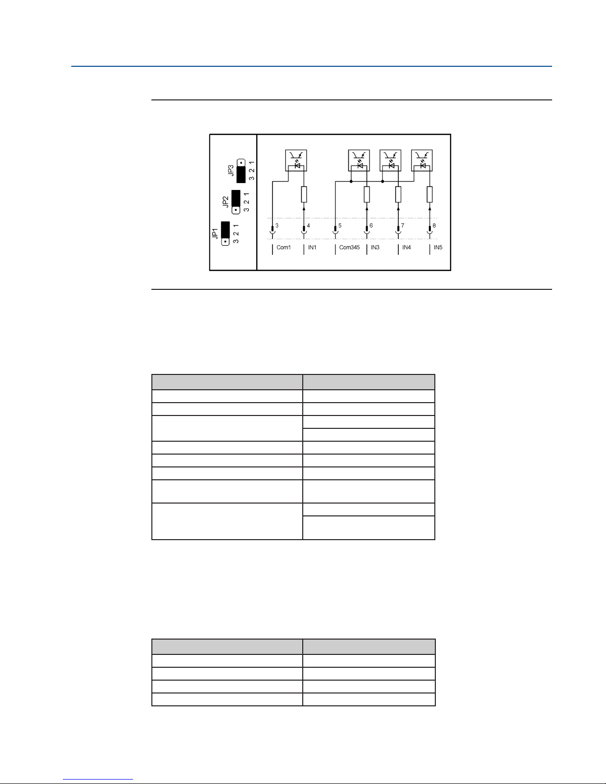
User Instructions
Part Number IOM – 87376-7 July 2016, Rev 1.
Figure 77 1 Separated Input and 3 Inputs with Same Common
Input In2 is disabled.
26.2 Binary Outputs
Table 27. Output Data Table
Parameter Value
Count 8
Power supply 24VDC nominal
Range
Max voltage drop at set output 1V
Output voltage at non-set output <1V
Maximum current per output 500mA (short circuit proof)
Maximum permissible total current
for all outputs
Fuse (Fuse F2, see Figure 74):
Binary outputs with external supply are separated from other controllers via optocouplers.
26.3 Analog Inputs
Input 1: Reference value
11 to 35VDC
(either from internal or external)
4A
4A time-lag
(Littelfuse 454 NANO2 Slo-BloQ
®
)
Table 28. Analag Input 1 Table
Current range 0-25mA
Resolution 14-bit
Accuracy 0.5%
Input resistance 60 Ohm
Analog Input 1 is electrically isolated from the rest of the control system.
Input 2: External actual value
Parameter Value
75

User Instructions
Part Number IOM – 87376-7 July 2016, Rev 1.0
Only in conjunction with the PID controller.
Table 29. Analog Input 2 Table
Parameter Value
Current range 0-20, 8mA
Resolution 10-bit
Accuracy 0.5%
Input resistance 120 Ohm
Jumper JP6 can be used to switch Analog Input 2 from a passive input (default) to an input with
24-V power supply (for 4-20 mA, two-wire transmitters).
NOTE:
The earth potential from Analog Input 2 is the common earth of the control system and the
auxiliary power supply (see Section 33.5).
26.4 Analog Outputs
Table 30. Analog Outputs Table
Parameter Value
Count 1
Current range 0-20, 8mA
Resolution 14-bit
Accuracy 0.5%
Max load 600 Ohm
Reference ground is the common ground of the controller and the auxiliary voltage (see
Section 33.5).
26.5 Auxiliary Voltage Input and Output
Table 31. Auxilliary Voltage Input and Output Table
Parameter Value
Input voltage range (auxiliary voltage input) 20-30VDC
Maximum current consumtion(auxiliary voltage
input)
Maximum current consumption in power-save
mode (auxiliary voltage input)
Output voltage (auxiliary voltage output) typically 23VMax
Output current (auxiliary voltage output) 200mA Resistance
Of ground potential vs. body typically 500kOhm
Capacitance of ground potential vs. body typically 100nF
Voltage of ground potential vs. body max. 40Vs
Fuse
500mA
120mA
1A time-lag
(Littelfuse 454 NANO2 Slo-
®
BloQ
)
Ground potential is the common ground of the controller and the analogue inputs and outputs.
The auxiliary voltage output can be set by the menu P6.5 (see Section 18.5).
76

User Instructions
Part Number IOM – 87376-7 July 2016, Rev 1.
The power-save mode is dened as follows:
• No power supply (the controller is powered exclusively through the 24V auxiliary
voltage input).
• The lighting of the LCD display switches o automatically.
• No additional hardware options available (Probus Interface, DeviceNet interface, relay
board, etc.).
• Binary outputs and the mA output are not enables; when activating, the respective
currents must be added to the total current.
26.6 Connections for Non-Explosion Proof Version
Table 32. Connections for Non-Explosionproof Version Table
Parameter Value
Power/motor
Control signals
Industrial plug with 6 pins screw connection
16A, max. 2.5mm2 , AWG14
Industrial plug with 24 pins screw connection
16A, max. 2.5mm2 , AWG14
Optionally, contacts are available in crimp or cage clamp designs.
26.7 Connections for Explosion Proof Version
Table 33. Connections for Explosionproof Version Table
Parameter Value
Power/motor
Control signals
Terminals with screw connection
16A, 0.5 to 4mm2 , AWG20 and AWG12
Terminals with screw connection
4A, 05 to 2.5mm2 , AWG20 and AWG14
77

User Instructions
Part Number IOM – 87376-7 July 2016, Rev 1.0
Appendix A: List of Figures
Figure 1 RTS FQ Fail-Safe Quarter-Turn Series ...............................................................................................1
Figure 2 Cut-out of the RTS FQ Fail-Safe Quarter-Turn Series ..................................................................2
Figure 3 Fail-safe Open Version ...........................................................................................................................3
Figure 4 Fail-safe Close Version ...........................................................................................................................3
Figure 5 Mechanical End Stop (1) .................................................................................................................... 10
Figure 6 Mechanical End Stop (2) .................................................................................................................... 10
Figure 7 Mechanical End Stop (3) .................................................................................................................... 11
Figure 8 RTS CM Compact Series Overview ................................................................................................. 20
Figure 9 Nameplate .............................................................................................................................................. 20
Figure 10 Nameplate Position ............................................................................................................................. 21
Figure 11 Nameplate of the Actuator for Operation in Explosive Atmosphere ................................ 21
Figure 12 Clockwise = Close ................................................................................................................................ 23
Figure 13 Counter Clockwise = Open ...............................................................................................................23
Figure 14 Label ......................................................................................................................................................... 25
Figure 15 Tag ............................................................................................................................................................. 25
Figure 16 RTS CM Compact Series Installation ............................................................................................. 28
Figure 17 RTS CM Compact Series Control System ..................................................................................... 29
Figure 18 Power Supply Connections .............................................................................................................. 31
Figure 19 Terminal Box .......................................................................................................................................... 32
Figure 20 Selector/Control Switch .....................................................................................................................34
Figure 21 Control Switch (First Menu Item).................................................................................................... 34
Figure 22 Display (1) ............................................................................................................................................... 34
Figure 23 Selector Switch in Neutral Position (1) ......................................................................................... 35
Figure 24 Selector Switch Flipped Up (1) ........................................................................................................ 35
Figure 25 Selector Switch in Neutral Position (2) ......................................................................................... 35
Figure 26 Display (2) ............................................................................................................................................... 36
78

User Instructions
Part Number IOM – 87376-7 July 2016, Rev 1.
Figure 27 Display (3) ............................................................................................................................................... 36
Figure 28 Selector Switch Flipped Down ........................................................................................................ 37
Figure 29 Display (4) ............................................................................................................................................... 37
Figure 30 Display (5) ............................................................................................................................................... 38
Figure 31 Selector Switch in Neutral Position (3) ......................................................................................... 38
Figure 32 Display (6) ............................................................................................................................................... 38
Figure 33 Selector Switch in Neutral Position (4) ......................................................................................... 39
Figure 34 Selector Switch Flipped Up (2) ........................................................................................................ 39
Figure 35 Selector Switch in Neutral Position (5) ......................................................................................... 39
Figure 36 Display (7) ............................................................................................................................................... 40
Figure 37 Display (8) ............................................................................................................................................... 40
Figure 38 Selector/Control Switch Operating Unit ......................................................................................41
Figure 39 Display (9) ............................................................................................................................................... 42
Figure 40 Display (10) .............................................................................................................................................42
Figure 41 LED Display .............................................................................................................................................43
Figure 42 Neutral Position .................................................................................................................................... 44
Figure 43 Slight Switch Flip (it will move to the next parameter) ......................................................... 44
Figure 44 Halfway Switch Flip (it will jump to the next parameter category) ...................................45
Figure 45 Full Switch Flip (it will jump to the end of the menu) ............................................................. 45
Figure 46 Display (11) .............................................................................................................................................46
Figure 47 Display (12) .............................................................................................................................................47
Figure 48 Selector/Control Switch (2) ..............................................................................................................47
Figure 49 Control Switch Flipped Down .........................................................................................................48
Figure 50 Display (13) .............................................................................................................................................48
Figure 51 Selector Switch in Neutral Position (6) ......................................................................................... 48
Figure 52 Selector Switch Flipped Up (3) ........................................................................................................ 49
Figure 53 Selector Switch in Neutral Position (8) ......................................................................................... 49
Figure 54 Display (14) .............................................................................................................................................49
Figure 55 Display (15) .............................................................................................................................................50
Figure 56 Control Switch Flipped Up ................................................................................................................ 50
Figure 57 Display (16) .............................................................................................................................................50
Figure 58 Selector Switch Flipped Halfway Up ............................................................................................. 51
Figure 59 Display (17) .............................................................................................................................................51
Figure 60 Display (18) .............................................................................................................................................60
Figure 61 Step Mode Operation ......................................................................................................................... 66
Figure 62 Assigning the Position to the Setpoint ........................................................................................ 69
Figure 63 Torque Characteristics ........................................................................................................................ 71
Figure 64 Binary Outputs Display ...................................................................................................................... 74
Figure 65 Binary Inputs Display .......................................................................................................................... 75
Figure 66 Analogue Values Display ................................................................................................................... 75
Figure 67 Firmware Display .................................................................................................................................. 76
Figure 68 Serial Number Display ........................................................................................................................76
Figure 69 Counter Values Display ...................................................................................................................... 77
79

User Instructions
Part Number IOM – 87376-7 July 2016, Rev 1.0
Figure 70 Infrared Connection ............................................................................................................................ 78
Figure 71 Logic Board of Controller .................................................................................................................. 82
Figure 72 Current/Voltage Relation ..................................................................................................................93
Figure 73 Control Unit ............................................................................................................................................93
Figure 74 Logic Board ............................................................................................................................................94
Figure 75 5 Inputs with Same Common .......................................................................................................... 94
Figure 76 2 Separated Groups of 2 Inputs with Same Ground................................................................94
Figure 77 3 Separated Inputs .............................................................................................................................. 95
Figure 78 3 Inputs with Same Common and 1 Separated Input ............................................................ 95
Figure 79 1 Separated Input and 3 Inputs with Same Common ............................................................ 96
Appendix B: List of Tables
Table 1. Torque Thread Table (1) ........................................................................................................................7
Table 2. Lubrication Utilization (1) .................................................................................................................17
Table 3. Torque Thread Table (2) .....................................................................................................................29
Table 4. LED Function Table .............................................................................................................................. 43
Table 5. Operating Mode Table ....................................................................................................................... 45
Table 6. Selector Switch Position Table.........................................................................................................46
Table 7. End Limit Table ......................................................................................................................................54
Table 8. Torque Table ...........................................................................................................................................55
Table 9. Speed Table ............................................................................................................................................ 56
Table 10. Ramp Table ............................................................................................................................................. 56
Table 11. Control Table .......................................................................................................................................... 57
Table 12. Password Table ...................................................................................................................................... 57
Table 13. Position Table ........................................................................................................................................ 58
Table 14. Binary Inputs Table .............................................................................................................................. 59
Table 15. Binary Outputs Table ..........................................................................................................................62
Table 16. Position Output Table ......................................................................................................................... 65
Table 17. Step Mode Table ................................................................................................................................... 66
Table 18. Positioner Table .................................................................................................................................... 67
Table 19. Controller Table..................................................................................................................................... 69
Table 20. Characteristic Curves Table .............................................................................................................. 72
Table 21. Identication Table .............................................................................................................................. 72
Table 22. Miscellaneous Table ............................................................................................................................ 73
Table 23. Error List Table ....................................................................................................................................... 81
Table 24. Fuses on the Logic Board .................................................................................................................. 82
Table 25. Lubrication Utilization (2) ................................................................................................................. 84
80

User Instructions
Part Number IOM – 87376-7 July 2016, Rev 1.
Table 26. Output Data - Standard Version Table ......................................................................................... 90
Table 27. Output Data - 24VDC Version Table ..............................................................................................90
Table 28. Power Supply - Power Electronics - Standard Version Table................................................ 91
Table 29. Power Supply - Power Electronics - 24VDC Version Table .................................................... 91
Table 30. Output Data - Standard Version FQ06/FQ20 Table .................................................................. 92
Table 31. Power Supply - Power Electronics - Standard Version FQ06/FQ20 Table ......................... 92
Table32. Input Data Table ...................................................................................................................................93
Table 33. Output Data ........................................................................................................................................... 96
Table 34. Analag Input 1 Table ........................................................................................................................... 96
Table 35. Analog Input 2 Table ........................................................................................................................... 97
Table 36. Analog Outputs Table ......................................................................................................................... 97
Table 37. Auxilliary Voltage Input and Output Table .................................................................................97
Table 38. Connections for Non-Explosion Proof Version Table ...............................................................98
Table 39. Connections for Explosion Proof Version Table .........................................................................98
Index
A
Ambient temperature, 5, 17, 24
Analog values, 75
Auxiliary voltage, 97
B
Binary inputs, 58, 59, 75, 93,
Binary outputs, 61, 62, 74, 96
Bluetooth communication, 47
Bluetooth Link, 79
Bore pattern, 28
Bus watchdog, 81
C
Centring ring, 28
Certicate of Conformity, 89
Characteristic, 71, 72
Commissioning, 9, 14, 25, 32, 53, 79
Conguration, 44, 46, 47
Connection compartment, 20, 22, 26
Control switch, 33, 34, 41, 46, 47
Control unit, 8, 20, 22, 41, 76, 93
Cover, 9, 11, 22, 40, 41, 82
D
DeviceNet, 71, 98
Direction of rotation, 3, 5, 22, 23, 54,
Display, 42, 43, 74, 75
E
Emergency position, 58, 60, 67, 70
End limit, 33, 40, 53
81

User Instructions
Part Number IOM – 87376-7 July 2016, Rev 1.0
82

User Instructions
Part Number IOM – 87376-7 July 2016, Rev 1.
World Area Conguration Centers (WACC) oer sales support,
service, inventory and commissioning to our global customers.
Choose the WACC or sales oce nearest you:
NORTH AND SOUTH AMERICA
19200 Northwest Freeway
Houston, TX 77065
USA
T +1 281 477 4100
F +1 281 477 2809
Av. Hollingsworth
325, Iporanga Sorocaba
SP 18087-105
Brazil
T +55 15 3238 3788
F +55 15 3228 3300
ASIA PACIFIC
No. 9 Gul Road
#01-02 Singapore 629361
T +65 6501 4600
F +65 6268 0028
No.1 Lai Yuan Road
Wuqing Development Area
Tianjin 301700
P.R. China
T +86 22 8212 3300
F +86 22 8212 3308
For complete list of sales and manufacturing sites, please visit
www.emersonprocess.com/valveautomationlocations
Or contact us at info.valveautomation@emerson.com
MIDDLE EAST AND AFRICA
P. O. Box 17033
Dubai
United Arab Emirates
T +971 4 811 8100
F +971 4 886 5465
P. O. Box 10305
Jubail 31961
Saudi Arabia
T +966 3 340 8650
F +966 3 340 8790
24 Angus Crescent
Longmeadow Business Estate
East P.O. Box 6908; Greenstone
1616 Modderfontein, Extension 5
South Africa
T +27 11 451 3700
F +27 11 451 3800
EUROPE
Berenyi u. 72- 100
Videoton Industry Park
Building #230
Székesfehérvár 8000
Hungary
T +36 22 53 09 50
F +36 22 54 37 00
www.emersonprocess.com/valveautomation
©2016 Emerson Process Management. All rights reserved.
The Emerson logo is a trademark and service mark of Emerson
Electric Co. All other marks are property of their respective
owners.
The contents of this publication are presented for information
purposes only, and while every eort has been made to ensure
their accuracy, they are not to be construed as warranties or
guarantees, express or implied, regarding the products or
services described herein or their use or applicability. All sales are
governed by our terms and conditions, which are available on
request. The customer is solely responsible for the selection, use
and maintenance of the products and equipment. We reserve
the right to modify or improve the designs or specications of
our products at any time without notice.
83
 Loading...