

Page 1

EA Version
RTM-ATCA-F140
Installation and Use
P/N: 6806800M97A
October 2011
Embedded Computing for
Business-Critical Continuity
TM
Page 2

EA Version
©
2011 Emerson
All rights reserved.
Trademarks
Emerson, Business-Critical Continuity, Emerson Network Power and the Emerson Network Power logo are trademarks and service
marks of Emerson Electric Co.
owners.
®
is a trademark or registered trademark of Intel Corporation or its subsidiaries in the United States and other countries.
Intel
™
and all other Java-based marks are trademarks or registered trademarks of Sun Microsystems, Inc. in the U.S. and other
Java
countries.
®
Microsoft
Microsoft Corporation.
PICMG
Industrial Computer Manufacturers Group.
UNIX
, Windows® and Windows Me® are registered trademarks of Microsoft Corporation; and Windows XP™ is a trademark of
®
, CompactPCI®, AdvancedTCA™ and the PICMG, CompactPCI and AdvancedTCA logos are registered trademarks of the PCI
®
is a registered trademark of The Open Group in the United States and other countries.
©
2011 Emerson Electric Co. All other product or service names are the property of their respective
Notice
While reasonable efforts have been made to assure the accuracy of this document, Emerson assumes no liability resulting from any
omissions in this document, or from the use of the information obtained therein. Emerson reserves the right to revise this document
and to make changes from time to time in the content hereof without obligation of Emerson to notify any person of such revision or
changes.
Electronic versions of this material may be read online, downloaded for personal use, or referenced in another document as a URL to
a Emerson website. The text itself may not be published commercially in print or electronic form, edited, translated, or otherwise
altered without the permission of Emerson,
It is possible that this publication may contain reference to or information about Emerson products (machines and programs),
programming, or services that are not available in your country. Such references or information must not be construed to mean that
Emerson intends to announce such Emerson products, programming, or services in your country.
Limited and Restricted Rights Legend
If the documentation contained herein is supplied, directly or indirectly, to the U.S. Government, the following notice shall apply
unless otherwise agreed to in writing by Emerson.
Use, duplication, or disclosure by the Government is subject to restrictions as set forth in subparagraph (b)(3) of the Rights in
Technical Data clause at DFARS 252.227-7013 (Nov. 1995) and of the Rights in Noncommercial Computer Software and
Documentation clause at DFARS 252.227-7014 (Jun. 1995).
Contact Address
Emerson Network Power - Embedded Computing
2900 South Diablo Way, Suite 190
Tempe, AZ 85282
USA
Page 3

Contents
EA Version
Contents
About this Manual . . . . . . . . . . . . . . . . . . . . . . . . . . . . . . . . . . . . . . . . . . . . . . . . . . . . . . . . . . . . . . . . . . . . . . . 11
1 Introduction . . . . . . . . . . . . . . . . . . . . . . . . . . . . . . . . . . . . . . . . . . . . . . . . . . . . . . . . . . . . . . . . . . . . . . . . . 15
1.1 Features . . . . . . . . . . . . . . . . . . . . . . . . . . . . . . . . . . . . . . . . . . . . . . . . . . . . . . . . . . . . . . . . . . . . . . . . . . . 15
1.2 Standard Compliances . . . . . . . . . . . . . . . . . . . . . . . . . . . . . . . . . . . . . . . . . . . . . . . . . . . . . . . . . . . . . . 16
1.3 Mechanical Data . . . . . . . . . . . . . . . . . . . . . . . . . . . . . . . . . . . . . . . . . . . . . . . . . . . . . . . . . . . . . . . . . . . 19
1.4 Ordering Information . . . . . . . . . . . . . . . . . . . . . . . . . . . . . . . . . . . . . . . . . . . . . . . . . . . . . . . . . . . . . . . 19
2 Hardware Preparation and Installation . . . . . . . . . . . . . . . . . . . . . . . . . . . . . . . . . . . . . . . . . . . . . . . . . 21
2.1 Overview . . . . . . . . . . . . . . . . . . . . . . . . . . . . . . . . . . . . . . . . . . . . . . . . . . . . . . . . . . . . . . . . . . . . . . . . . . 21
2.2 Unpacking and Inspecting the RTM . . . . . . . . . . . . . . . . . . . . . . . . . . . . . . . . . . . . . . . . . . . . . . . . . . . 21
2.3 Environmental and Power Requirements . . . . . . . . . . . . . . . . . . . . . . . . . . . . . . . . . . . . . . . . . . . . . . 22
2.3.1 Environmental Requirements. . . . . . . . . . . . . . . . . . . . . . . . . . . . . . . . . . . . . . . . . . . . . . . . . . 22
2.4 RTM Installation and Removal . . . . . . . . . . . . . . . . . . . . . . . . . . . . . . . . . . . . . . . . . . . . . . . . . . . . . . . . 24
2.4.1 Installing the RTM . . . . . . . . . . . . . . . . . . . . . . . . . . . . . . . . . . . . . . . . . . . . . . . . . . . . . . . . . . . . 25
2.4.2 Removing the RTM . . . . . . . . . . . . . . . . . . . . . . . . . . . . . . . . . . . . . . . . . . . . . . . . . . . . . . . . . . . 28
3 Controls, LEDs, and Connectors . . . . . . . . . . . . . . . . . . . . . . . . . . . . . . . . . . . . . . . . . . . . . . . . . . . . . . . . 31
3.1 Overview . . . . . . . . . . . . . . . . . . . . . . . . . . . . . . . . . . . . . . . . . . . . . . . . . . . . . . . . . . . . . . . . . . . . . . . . . . 31
3.2 Face Plate Connectors and LEDs . . . . . . . . . . . . . . . . . . . . . . . . . . . . . . . . . . . . . . . . . . . . . . . . . . . . . . 31
3.2.1 LEDs. . . . . . . . . . . . . . . . . . . . . . . . . . . . . . . . . . . . . . . . . . . . . . . . . . . . . . . . . . . . . . . . . . . . . . . . 33
4 Functional Description . . . . . . . . . . . . . . . . . . . . . . . . . . . . . . . . . . . . . . . . . . . . . . . . . . . . . . . . . . . . . . . . 35
4.1 Block Diagram . . . . . . . . . . . . . . . . . . . . . . . . . . . . . . . . . . . . . . . . . . . . . . . . . . . . . . . . . . . . . . . . . . . . . 35
4.2 Management Resources . . . . . . . . . . . . . . . . . . . . . . . . . . . . . . . . . . . . . . . . . . . . . . . . . . . . . . . . . . . . . 36
4.2.1 FRU Serial EEPROM . . . . . . . . . . . . . . . . . . . . . . . . . . . . . . . . . . . . . . . . . . . . . . . . . . . . . . . . . . . 36
4.2.2 Temperature Sensors. . . . . . . . . . . . . . . . . . . . . . . . . . . . . . . . . . . . . . . . . . . . . . . . . . . . . . . . . 36
4.2.3 LEDs. . . . . . . . . . . . . . . . . . . . . . . . . . . . . . . . . . . . . . . . . . . . . . . . . . . . . . . . . . . . . . . . . . . . . . . . 37
4.2.4 I2C Address Map . . . . . . . . . . . . . . . . . . . . . . . . . . . . . . . . . . . . . . . . . . . . . . . . . . . . . . . . . . . . . 38
4.3 1 Gbps SFP Ports . . . . . . . . . . . . . . . . . . . . . . . . . . . . . . . . . . . . . . . . . . . . . . . . . . . . . . . . . . . . . . . . . . . 38
4.3.1 Connectivity. . . . . . . . . . . . . . . . . . . . . . . . . . . . . . . . . . . . . . . . . . . . . . . . . . . . . . . . . . . . . . . . . 38
4.3.2 Front-Blade Port Mapping . . . . . . . . . . . . . . . . . . . . . . . . . . . . . . . . . . . . . . . . . . . . . . . . . . . . . 39
4.3.3 SFP Connection . . . . . . . . . . . . . . . . . . . . . . . . . . . . . . . . . . . . . . . . . . . . . . . . . . . . . . . . . . . . . . 39
RTM-ATCA-F140 Installation and Use (6806800M97A)
3
Page 4

Contents
Contents
EA Version
Contents
4.3.3.1 I2C Bus . . . . . . . . . . . . . . . . . . . . . . . . . . . . . . . . . . . . . . . . . . . . . . . . . . . . . . . . . . . . 40
4.3.3.2 SFP Status Signals . . . . . . . . . . . . . . . . . . . . . . . . . . . . . . . . . . . . . . . . . . . . . . . . . . . 40
4.3.3.3 SFP Control Signals . . . . . . . . . . . . . . . . . . . . . . . . . . . . . . . . . . . . . . . . . . . . . . . . . . 40
4.4 10 Gbps SFP+ Ports . . . . . . . . . . . . . . . . . . . . . . . . . . . . . . . . . . . . . . . . . . . . . . . . . . . . . . . . . . . . . . . . . 40
4.4.1 Connectivity. . . . . . . . . . . . . . . . . . . . . . . . . . . . . . . . . . . . . . . . . . . . . . . . . . . . . . . . . . . . . . . . . 41
4.4.2 Front-Blade Port Mapping . . . . . . . . . . . . . . . . . . . . . . . . . . . . . . . . . . . . . . . . . . . . . . . . . . . . . 41
4.4.3 BCM8727 Configuration Flash . . . . . . . . . . . . . . . . . . . . . . . . . . . . . . . . . . . . . . . . . . . . . . . . . 41
4.4.4 Transmitter Control . . . . . . . . . . . . . . . . . . . . . . . . . . . . . . . . . . . . . . . . . . . . . . . . . . . . . . . . . . 41
4.4.5 BCM8727 Status . . . . . . . . . . . . . . . . . . . . . . . . . . . . . . . . . . . . . . . . . . . . . . . . . . . . . . . . . . . . . 42
4.4.6 SFP+ Connection. . . . . . . . . . . . . . . . . . . . . . . . . . . . . . . . . . . . . . . . . . . . . . . . . . . . . . . . . . . . . 42
4.4.6.1 I2C Bus . . . . . . . . . . . . . . . . . . . . . . . . . . . . . . . . . . . . . . . . . . . . . . . . . . . . . . . . . . . . 42
4.4.6.2 SFP+ Status Signals . . . . . . . . . . . . . . . . . . . . . . . . . . . . . . . . . . . . . . . . . . . . . . . . . . 43
4.4.6.3 SFP Control Signals . . . . . . . . . . . . . . . . . . . . . . . . . . . . . . . . . . . . . . . . . . . . . . . . . . 43
4.4.6.4 PHY Management Interfaces . . . . . . . . . . . . . . . . . . . . . . . . . . . . . . . . . . . . . . . . . 43
4.5 10Gbps Fabric Ports . . . . . . . . . . . . . . . . . . . . . . . . . . . . . . . . . . . . . . . . . . . . . . . . . . . . . . . . . . . . . . . . 43
4.5.1 Fabric Connectivity. . . . . . . . . . . . . . . . . . . . . . . . . . . . . . . . . . . . . . . . . . . . . . . . . . . . . . . . . . . 44
4.5.2 Fabric Front Blade Port Mapping . . . . . . . . . . . . . . . . . . . . . . . . . . . . . . . . . . . . . . . . . . . . . . . 44
4.5.3 BCM84754 Configuration Flash . . . . . . . . . . . . . . . . . . . . . . . . . . . . . . . . . . . . . . . . . . . . . . . . 44
4.5.4 Transmitter Control . . . . . . . . . . . . . . . . . . . . . . . . . . . . . . . . . . . . . . . . . . . . . . . . . . . . . . . . . . 44
4.5.5 BCM84754 Status . . . . . . . . . . . . . . . . . . . . . . . . . . . . . . . . . . . . . . . . . . . . . . . . . . . . . . . . . . . . 45
4.5.6 Fabric SFP+ Connection . . . . . . . . . . . . . . . . . . . . . . . . . . . . . . . . . . . . . . . . . . . . . . . . . . . . . . . 45
4.5.6.1 SFP+ I2C Bus . . . . . . . . . . . . . . . . . . . . . . . . . . . . . . . . . . . . . . . . . . . . . . . . . . . . . . . 45
4.5.6.2 SFP+ Status Signals . . . . . . . . . . . . . . . . . . . . . . . . . . . . . . . . . . . . . . . . . . . . . . . . . . 45
4.5.6.3 SFP+ Control Signals . . . . . . . . . . . . . . . . . . . . . . . . . . . . . . . . . . . . . . . . . . . . . . . . 45
4.5.7 PHY Management Interfaces . . . . . . . . . . . . . . . . . . . . . . . . . . . . . . . . . . . . . . . . . . . . . . . . . . 46
4.6 40Gbps Fabric Ports . . . . . . . . . . . . . . . . . . . . . . . . . . . . . . . . . . . . . . . . . . . . . . . . . . . . . . . . . . . . . . . . 46
4.6.1 Fabric Connectivity. . . . . . . . . . . . . . . . . . . . . . . . . . . . . . . . . . . . . . . . . . . . . . . . . . . . . . . . . . . 46
4.6.2 Fabric Front Blade Port Mapping . . . . . . . . . . . . . . . . . . . . . . . . . . . . . . . . . . . . . . . . . . . . . . . 47
4.6.3 BCM84740 Configuration Flash . . . . . . . . . . . . . . . . . . . . . . . . . . . . . . . . . . . . . . . . . . . . . . . . 47
4.6.4 Transmitter Control . . . . . . . . . . . . . . . . . . . . . . . . . . . . . . . . . . . . . . . . . . . . . . . . . . . . . . . . . . 47
4.6.5 BCM84740 Status . . . . . . . . . . . . . . . . . . . . . . . . . . . . . . . . . . . . . . . . . . . . . . . . . . . . . . . . . . . . 48
4.6.6 Fabric QSFP+ Connection . . . . . . . . . . . . . . . . . . . . . . . . . . . . . . . . . . . . . . . . . . . . . . . . . . . . . 48
4.6.6.1 QSFP+ I2C Bus . . . . . . . . . . . . . . . . . . . . . . . . . . . . . . . . . . . . . . . . . . . . . . . . . . . . . . 49
4.6.6.2 QSFP+ Status Signals . . . . . . . . . . . . . . . . . . . . . . . . . . . . . . . . . . . . . . . . . . . . . . . . 49
4.6.6.3 QSFP+ Control Signals . . . . . . . . . . . . . . . . . . . . . . . . . . . . . . . . . . . . . . . . . . . . . . . 49
4.6.7 PHY Management Interfaces . . . . . . . . . . . . . . . . . . . . . . . . . . . . . . . . . . . . . . . . . . . . . . . . . . 49
4
RTM-ATCA-F140 Installation and Use (6806800M97A)
Page 5

Contents
EA Version
4.7 GPS Connectors . . . . . . . . . . . . . . . . . . . . . . . . . . . . . . . . . . . . . . . . . . . . . . . . . . . . . . . . . . . . . . . . . . . . 50
4.7.1 1PPS Input . . . . . . . . . . . . . . . . . . . . . . . . . . . . . . . . . . . . . . . . . . . . . . . . . . . . . . . . . . . . . . . . . . 50
4.7.2 10MHz Input . . . . . . . . . . . . . . . . . . . . . . . . . . . . . . . . . . . . . . . . . . . . . . . . . . . . . . . . . . . . . . . . 51
4.7.3 Time-Of-Day Input . . . . . . . . . . . . . . . . . . . . . . . . . . . . . . . . . . . . . . . . . . . . . . . . . . . . . . . . . . . 51
4.8 FPGA . . . . . . . . . . . . . . . . . . . . . . . . . . . . . . . . . . . . . . . . . . . . . . . . . . . . . . . . . . . . . . . . . . . . . . . . . . . . . . 52
4.8.1 Front-blade Interface . . . . . . . . . . . . . . . . . . . . . . . . . . . . . . . . . . . . . . . . . . . . . . . . . . . . . . . . . 52
4.8.2 SFP/SFP+/QSFP+ Control and Status . . . . . . . . . . . . . . . . . . . . . . . . . . . . . . . . . . . . . . . . . . . . 52
4.8.3 BCM8727 Control and Status . . . . . . . . . . . . . . . . . . . . . . . . . . . . . . . . . . . . . . . . . . . . . . . . . . 53
4.8.4 BCM84754 Control and Status . . . . . . . . . . . . . . . . . . . . . . . . . . . . . . . . . . . . . . . . . . . . . . . . . 53
4.8.5 BCM84740 Control and Status . . . . . . . . . . . . . . . . . . . . . . . . . . . . . . . . . . . . . . . . . . . . . . . . . 54
4.8.6 Reset Handling . . . . . . . . . . . . . . . . . . . . . . . . . . . . . . . . . . . . . . . . . . . . . . . . . . . . . . . . . . . . . . 54
4.8.7 Synchronous Ethernet Clock Recovery . . . . . . . . . . . . . . . . . . . . . . . . . . . . . . . . . . . . . . . . . . 54
4.8.8 SPI Flash . . . . . . . . . . . . . . . . . . . . . . . . . . . . . . . . . . . . . . . . . . . . . . . . . . . . . . . . . . . . . . . . . . . . 55
4.8.9 FPGA Register Map . . . . . . . . . . . . . . . . . . . . . . . . . . . . . . . . . . . . . . . . . . . . . . . . . . . . . . . . . . . 55
4.8.10 FPGA Configuration . . . . . . . . . . . . . . . . . . . . . . . . . . . . . . . . . . . . . . . . . . . . . . . . . . . . . . . . . . 56
4.9 Reset Scheme . . . . . . . . . . . . . . . . . . . . . . . . . . . . . . . . . . . . . . . . . . . . . . . . . . . . . . . . . . . . . . . . . . . . . . 56
4.10 Zone 3 Isolation . . . . . . . . . . . . . . . . . . . . . . . . . . . . . . . . . . . . . . . . . . . . . . . . . . . . . . . . . . . . . . . . . . . . 56
4.11 Power Management . . . . . . . . . . . . . . . . . . . . . . . . . . . . . . . . . . . . . . . . . . . . . . . . . . . . . . . . . . . . . . . . 57
4.11.1 Power Requirements . . . . . . . . . . . . . . . . . . . . . . . . . . . . . . . . . . . . . . . . . . . . . . . . . . . . . . . . . 57
A Related Documentation . . . . . . . . . . . . . . . . . . . . . . . . . . . . . . . . . . . . . . . . . . . . . . . . . . . . . . . . . . . . . . . 59
A.1 Emerson Network Power - Embedded Computing Documents . . . . . . . . . . . . . . . . . . . . . . . . . . . 59
Safety Notes . . . . . . . . . . . . . . . . . . . . . . . . . . . . . . . . . . . . . . . . . . . . . . . . . . . . . . . . . . . . . . . . . . . . . . . . . . . . . 61
Sicherheitshinweise . . . . . . . . . . . . . . . . . . . . . . . . . . . . . . . . . . . . . . . . . . . . . . . . . . . . . . . . . . . . . . . . . . . . . . 65
Index . . . . . . . . . . . . . . . . . . . . . . . . . . . . . . . . . . . . . . . . . . . . . . . . . . . . . . . . . . . . . . . . . . . . . . . . . . . . . . . . . . . 69
RTM-ATCA-F140 Installation and Use (6806800M97A)
5
Page 6

Contents
Contents
EA Version
Contents
6
RTM-ATCA-F140 Installation and Use (6806800M97A)
Page 7

List of Tables
Table 1-1 Standard Compliances . . . . . . . . . . . . . . . . . . . . . . . . . . . . . . . . . . . . . . . . . . . . . . . . . . . . . . . 16
EA Version
Table 1-2 RTM-ATCA-F140 Mechanical Data . . . . . . . . . . . . . . . . . . . . . . . . . . . . . . . . . . . . . . . . . . . . . 19
Table 1-3 Blade Variants - Ordering Information . . . . . . . . . . . . . . . . . . . . . . . . . . . . . . . . . . . . . . . . . 19
Table 2-1 Environmental Conditions . . . . . . . . . . . . . . . . . . . . . . . . . . . . . . . . . . . . . . . . . . . . . . . . . . . . 23
Table 4-1 Temperature Sensor Thresholds . . . . . . . . . . . . . . . . . . . . . . . . . . . . . . . . . . . . . . . . . . . . . . 36
Table 4-2 PCF 8574 Port Usage . . . . . . . . . . . . . . . . . . . . . . . . . . . . . . . . . . . . . . . . . . . . . . . . . . . . . . . . 37
Table 4-3 I2C Bus Address Map . . . . . . . . . . . . . . . . . . . . . . . . . . . . . . . . . . . . . . . . . . . . . . . . . . . . . . . . 38
Table 4-4 Front-Blade Port Mapping . . . . . . . . . . . . . . . . . . . . . . . . . . . . . . . . . . . . . . . . . . . . . . . . . . . . 39
Table 4-5 SFP Connector Pin Assignment . . . . . . . . . . . . . . . . . . . . . . . . . . . . . . . . . . . . . . . . . . . . . . . 39
Table 4-6 SFP+ Connector Pin Assignment . . . . . . . . . . . . . . . . . . . . . . . . . . . . . . . . . . . . . . . . . . . . . . 42
Table 4-7 BCM8727 PHY Addressing . . . . . . . . . . . . . . . . . . . . . . . . . . . . . . . . . . . . . . . . . . . . . . . . . . . 43
Table 4-8 BCM84754 PHY Addressing . . . . . . . . . . . . . . . . . . . . . . . . . . . . . . . . . . . . . . . . . . . . . . . . . . 46
Table 4-9 QSFP+ Connector Pin Assignment . . . . . . . . . . . . . . . . . . . . . . . . . . . . . . . . . . . . . . . . . . . . . 48
Table 4-10 BCM84740 PHY Addressing . . . . . . . . . . . . . . . . . . . . . . . . . . . . . . . . . . . . . . . . . . . . . . . . . . 49
Table 4-11 1PPS Input Specifications . . . . . . . . . . . . . . . . . . . . . . . . . . . . . . . . . . . . . . . . . . . . . . . . . . . . 50
Table 4-12 10MHz Input Specifications . . . . . . . . . . . . . . . . . . . . . . . . . . . . . . . . . . . . . . . . . . . . . . . . . . 51
Table 4-13 Time-Of-Day RJ45 Pinout . . . . . . . . . . . . . . . . . . . . . . . . . . . . . . . . . . . . . . . . . . . . . . . . . . . . 51
Table 4-14 FPGA Configuration Controls . . . . . . . . . . . . . . . . . . . . . . . . . . . . . . . . . . . . . . . . . . . . . . . . . 56
Table 4-15 Power Requirements . . . . . . . . . . . . . . . . . . . . . . . . . . . . . . . . . . . . . . . . . . . . . . . . . . . . . . . . 57
Table A-1 Related Documentation . . . . . . . . . . . . . . . . . . . . . . . . . . . . . . . . . . . . . . . . . . . . . . . . . . . . . 59
RTM-ATCA-F140 Installation and Use (6806800M97A)
7
Page 8

List of Tables
EA Version
8
RTM-ATCA-F140 Installation and Use (6806800M97A)
Page 9

List of Figures
Figure 1-1 Declaration of Conformity - TBD . . . . . . . . . . . . . . . . . . . . . . . . . . . . . . . . . . . . . . . . . . 18
EA Version
Figure 3-1 Face Plate . . . . . . . . . . . . . . . . . . . . . . . . . . . . . . . . . . . . . . . . . . . . . . . . . . . . . . . . . . . . . . 32
Figure 4-1 Block Diagram . . . . . . . . . . . . . . . . . . . . . . . . . . . . . . . . . . . . . . . . . . . . . . . . . . . . . . . . . . 35
Figure 4-2 1GB Base Channel Interconnect . . . . . . . . . . . . . . . . . . . . . . . . . . . . . . . . . . . . . . . . . . . 38
Figure 4-3 Fabric 10 GB Interconnect . . . . . . . . . . . . . . . . . . . . . . . . . . . . . . . . . . . . . . . . . . . . . . . . 41
Figure 4-4 Fabric 10Gb Interconnect . . . . . . . . . . . . . . . . . . . . . . . . . . . . . . . . . . . . . . . . . . . . . . . . 44
Figure 4-5 Fabric 40Gb Interconnect . . . . . . . . . . . . . . . . . . . . . . . . . . . . . . . . . . . . . . . . . . . . . . . . 47
Figure 4-6 Synchronous Ethernet Reference Recovery . . . . . . . . . . . . . . . . . . . . . . . . . . . . . . . . . 55
RTM-ATCA-F140 Installation and Use (6806800M97A)
9
Page 10

List of Figures
EA Version
10
RTM-ATCA-F140 Installation and Use (6806800M97A)
Page 11

About this Manual
EA Version
Overview of Contents
This manual is divided into the following chapters and appendices.
Introduction describes the main features of the RTM.
Hardware Preparation and Installation installation prerequisites and the installation itself.
Controls, LEDs, and Connectors describes external interfaces such as connectors and LEDs.
Func tional Descr iption contains a block diagram of the RTM and provides some information
on the IPMI functionality of the RTM.
Related Documentation lists further Emerson user manuals that are related to the RTM and
the ATCA-F140.
Safety Notes summarizes the safety instructions in the manual.
Sicherheitshinweise is a German translation of the Safety Notes chapter.
Abbreviations
RTM-ATCA-F140 Installation and Use (6806800M97A)
This document uses the following abbreviations:
Abbreviation Definition
AMC Alarm Management Controller
ARP Address Resolution Protocol
ATCA Advanced Telecom Computing Architecture
BIX Base Interface Switch
CP-TA Communications Platforms Trade Association
FIX Fabric Interface Switch
IO Input/Output
PICMG PCI Industrial Computer Manufacturers Group
PCI Peripheral Component Interconnect
RTM Rear Transition Module
SPI Serial Peripheral Interface
11
Page 12

About this Manual
About this Manual
EA Version
Conventions
The following table describes the conventions used throughout this manual.
Notation Description
0x00000000 Typical notation for hexadecimal numbers (digits are
0b0000 Same for binary numbers (digits are 0 and 1)
bold Used to emphasize a word
Screen Used for on-screen output and code related elements
Courier + Bold Used to characterize user input and to separate it
Reference Used for references and for table and figure
File > Exit Notation for selecting a submenu
0 through F), for example used for addresses and
offsets
or commands in body text
from system output
descriptions
12
<text> Notation for variables and keys
[text] Notation for software buttons to click on the screen
and parameter description
... Repeated item for example node 1, node 2, ..., node
12
.
.
.
.. Ranges, for example: 0..4 means one of the integers
|Logical OR
Omission of information from example/command
that is not necessary at the time being
0,1,2,3, and 4 (used in registers)
RTM-ATCA-F140 Installation and Use (6806800M97A)
Page 13
About this Manual
Notation Description
EA Version
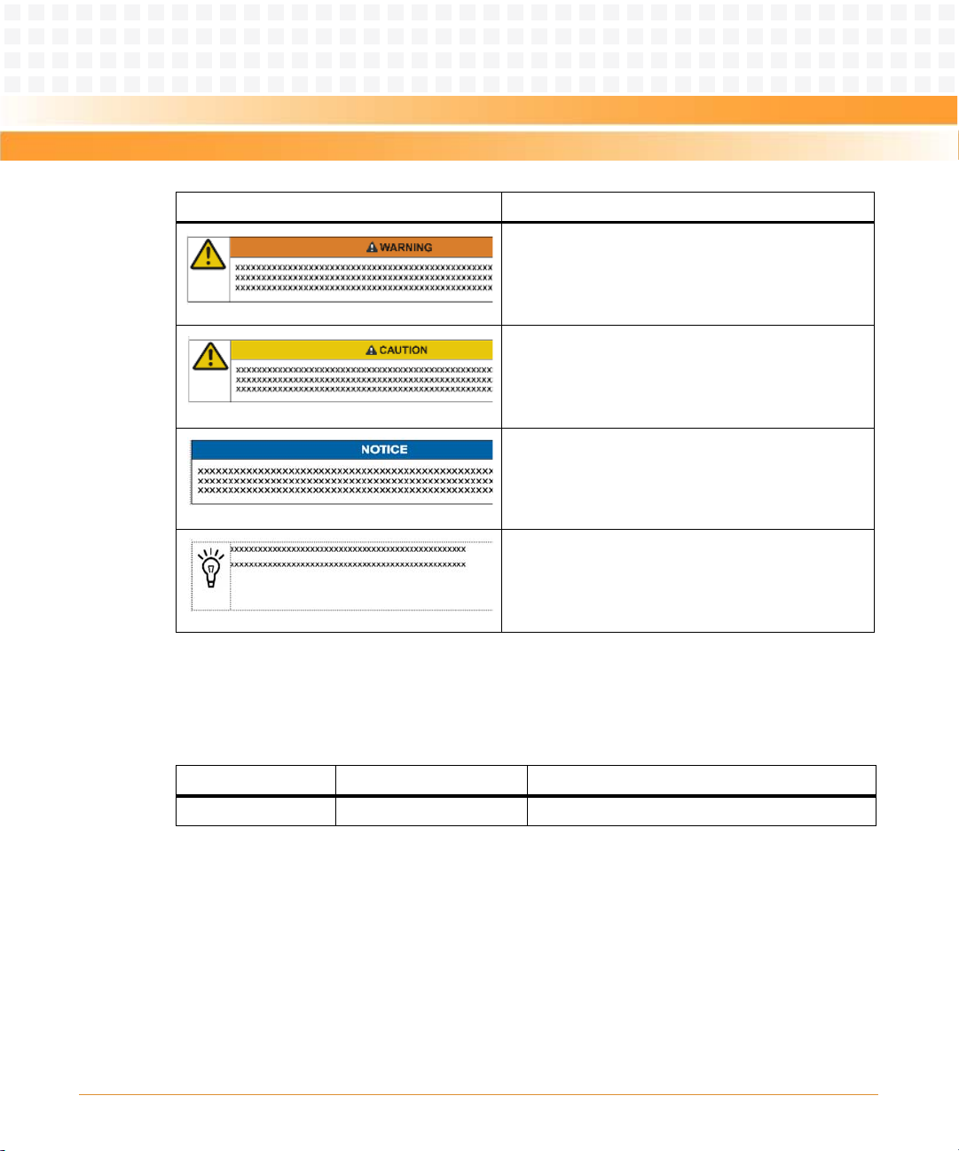
Summary of Changes
Indicates a hazardous situation which, if not avoided,
could result in death or serious injury
Indicates a hazardous situation which, if not avoided,
may result in minor or moderate injury
Indicates a property damage message
No danger encountered. Pay attention to important
information
RTM-ATCA-F140 Installation and Use (6806800M97A)
This manual has been revised and replaces all prior editions.
Part Number Publication Date Description
6806800M97A August 2011 First edition
13
Page 14

About this Manual
About this Manual
EA Version
14
RTM-ATCA-F140 Installation and Use (6806800M97A)
Page 15

Introduction
EA Version
1.1 Features
The RTM-ATCA-F140 provides the I/O connection for the ATCA-F140 switch blade towards the
back of the system. RTM-ATCA-F140 is directly connected to and powered by the front board.
The RTM-ATCA-F140 is a rear transition module (RTM) as defined in PICMG 3.0 Revision 3.0
Advanced TCA Base Specification and PICMG 3.1 Revision 1.0 Specification Ethernet/Fiber
Channel for AdvancedTCA Systems. It provides several Base and Fabric Channel Ethernet
interfaces connected to the front board through the Zone 3 connector.
The main features of the RTM-ATCA-F140 are:
Single slot RTM form factor (70mm x 322mm)
1x 40Gbit Ethernet uplink (FIX) according to IEEE 802.3ba with 1 QSFP+ type connector
4x 10Gbit Ethernet uplinks (FIX) according to IEEE 802.3ap with 4 SFP+ type connectors
Chapter 1
2x 10Gbit Ethernet uplinks (BIX) according to IEEE 802.3ap with 2 SFP+ type connectors
4x 1Gbit Ethernet interfaces (BIX) with 4 SFP type connectors
GPS 1PPS SMA input
GPS 10MHz SMA input
GPS time-of-day and optional 1PPS with RJ45 connector
Hot-plug ability
Serial EEPROM accessible by front-blade IPMC
Four status LEDs and ejector handle switch accessible by front-blade IPMC
RTM-ATCA-F140 Installation and Use (6806800M97A)
15
Page 16

Introduction
1.2 Standard Compliances
EA Version
The product is designed to meet the following standards.
Table 1-1 Standard Compliances
Standard Description
ANSI Fire Spread Criteria The product is designed to pass the ANSI T1.319-2002 fire
spread test method as well as the NEBS GR-63-CORE fire spread
test method.
AS/NZS CISPR 22 Class A
(Australia/New Zealand)
AT&T Document ATT-TP-76200 The product is designed to comply with the latest version of the
EN 55024 (EU) The product complies with EN55024 (EU) Information
EN 60950-1 This product complies with EN 60950-1 Safety of Information
EN55022 Class A (EU) The product complies with EN55022 Class A (EU), Information
ETSI Acoustic Noise ETS 300 753
Class 3.1
ETSI Stationary Use: EN 300 0192-3 Class 3.1
ETSI Storage EN 300 019-2-1
Class 1.2
ETSI Transportation: EN 300 0192-2 Class 2.3
The product complies with AS/NZS CISPR 22 Class A
(Australia/New Zealand), Limits and Methods of Measurement
of Radio Disturbance Characteristics of Information Technology
Equipment.
AT&T Document ATT-TP-76200: Network Equipment Power,
Grounding, Environmental, And Physical Design Requirements.
Technology Equipment - Immunity Characteristics - Limits and
Methods of Measurements.
Technology Equipment.
Technology Equipment - Radio Disturbance Characteristics Limits and Methods of Measurements.
The product will not prevent the system from complying
with the ETSI acoustic noise requirements per Class 3.1 of ETSI
ETS 300 753, Equipment Engineering (EE); Acoustic noise
emitted by
The product is designed to comply with ETSI Stationary Use: EN
300 019-2-3, Class 3.1 equipment (temperature controlled
locations).
The product is designed to comply with ETSI Storage: EN 300
019-2-1, Class 1.2 equipment (not temperature controlled
storage locations).
The product is designed to comply with ETSI Transportation: EN
300 019-2-2, Class 2.3 equipment (public transportation).
telecommunications equipment.
16
RTM-ATCA-F140 Installation and Use (6806800M97A)
Page 17

Introduction
Table 1-1 Standard Compliances (continued)
EA Version
Standard Description
FCC 47 CFR Part 15 Subpart B
(US), Class A
GR-1089 - Ports and Intrabuilding Lightning
GR-1089-CORE Products are designed to comply with all applicable
GR63-CORE The product is designed to comply with all applicable
IEC 60950-1 CB Scheme The product complies with IEC 60950-1 CB Scheme including all
NEBS Level 3 Module is designed to pass all testing to Criteria Level 3 per
Safety Mark for U.S. and Canada The product is designed to certify to UL/CSA No. 60950-1 with
UL/CSA No. 60950-1 The product complies with UL/CSA 60950-1Safety of
VCCI Class A (Japan) The product complies with VCCI Class A (Japan), Voluntary
The product complies with FCC 47 CFR Part 15 Subpart B (US),
Class A.
All externally accessible ports shall be designed to comply with
the applicable GR-1089 requirements for Telecommunication
Ports.
requirements for Type 2 Equipment referenced in Telcordia
Document GR-1089-CORE.
requirements of Telcordia GR-63-CORE, NEBS Requirements:
Physical Protection.
National Deviations Safety of Information Technology
Equipment. Testing shall be by an accredited lab.
Telcordia SR-3580.
no devi ation s and s hall bea r the Reco gni tion M ark o f an NRTL for
US and Canada.
Information Technology Equipment.
Control Council for Interference by Information Technology
Equipment.
RTM-ATCA-F140 Installation and Use (6806800M97A)
Verizon CHECKLIST The product is designed to comply with the latest version of the
Verizon Document VZ.NEBS.TE.NPI.2004.015: NEBS Checklist.
17
Page 18

Introduction
Figure 1-1 Declaration of Conformity - TBD
EA Version
18
RTM-ATCA-F140 Installation and Use (6806800M97A)
Page 19

Introduction
1.3 Mechanical Data
EA Version
Table 1-2 RTM-ATCA-F140 Mechanical Data
Data Value
Dimensions 8U x 6 HP form factor - 30 mm x 351 mm x 143 mm (including face plate
handles and alignment posts)
Weight 0.725 Kg
1.4 Ordering Information
The following table lists the blade variants that were available as of the time of writing this
manual. Consult your local Emerson sales representative for the availability of further variants.
Table 1-3 Blade Variants - Ordering Information
Part Number Description
RTM-ATCA-F140 RTM for the ATCA-F140 with SFP and SFP+ sockets
RTM-ATCA-F140 Installation and Use (6806800M97A)
19
Page 20

Introduction
EA Version
20
RTM-ATCA-F140 Installation and Use (6806800M97A)
Page 21

Hardware Preparation and Installation
EA Version
2.1 Overview
Inspect the shipment and unpack the RTM.
Make sure environmental and power requirements are met.
Install the RTM.
2.2 Unpacking and Inspecting the RTM
Damage of Circuits
Chapter 2
Electrostatic discharge and incorrect installation and removal of the blade can damage
circuits or shorten its life.
Before touching the blade or electronic components, make sure that you are working in
an ESD-safe environment.
The shelf should provide minimum airflow to the RTM slot according to the class B.4
requirements of the CP-TA Inter-operability document AdvancedTCA Book 1.1. This includes
the following:
2.0 cfm at 25 °C ambient temperature
2.8 cfm at 40 °C ambient temperature
4.4 cfm at 55 °C ambient temperature
Shipment Inspection
To inspect the shipment, perform the following steps:
1. Verify that you have received all items of your shipment:
Printed Quick Start Guide and Safety Notes Summary
RTM-ATCA-F140
RTM-ATCA-F140 Installation and Use (6806800M97A)
21
Page 22

Hardware Preparation and Installation
2. Check for damage and report any damage or differences to the customer service.
EA Version
3. Remove the desiccant bag shipped together with the blade and dispose of it according to
your country’s legislation.
The RTM is thoroughly inspected before shipment. If damage has occurred or items
missing during transportation, contact our customer's service immediately.
Remove the desiccant bag shipped together with the blade and dispose of it according to
your country’s legislation.
2.3 Environmental and Power Requirements
In order to meet the environmental requirements, the blade has to be tested in the system in
which it is to be installed.
Before you power up the blade, calculate the power needed according to your combination of
blade upgrades and accessories.
2.3.1 Environmental Requirements
The environmental conditions must be tested and proven in the shelf configuration used. The
conditions refer to the surrounding of the blade within the user environment.
22
The environmental requirements of the blade may be further limited down due to
installed accessories, such as hard disks or PMC modules, with more restrictive
environmental requirements.
Operating temperatures refer to the temperature of the air circulating around the blade
and not to the actual component temperature.
RTM-ATCA-F140 Installation and Use (6806800M97A)
Page 23

Hardware Preparation and Installation
Blade Damage
EA Version
Blade surface
Do not operate the blade outside the specified environmental limits. Make sure the
blade is completely dry and there is no moisture on any surface before applying power.
Blade Overheating and Blade Damage
Operating the blade without forced air cooling may lead to blade overheating and thus
blade damage.
When operating the blade, make sure that forced air cooling is available in the shelf.
Table 2-1 Environmental Conditions
Requirement Operating Non-Operating
Temperature and airflow per
CP-TA B.4
The RTM shall require no more
than 2.2 CFM at the inlet
ambient of 25°C (77°F).
Under abnormal Short Term
operating conditions such as an
air mover failure, an RTM shall
require no more than 3.0 CFM
at the inlet ambient of 40°C
(104°F).
The RTM shall require no more
than 3.2 CFM at the inlet
ambient of 40°C (104°F) under
normal operating conditions.
RTM-ATCA-F140 Installation and Use (6806800M97A)
Under abnormal Short Term
operating conditions such as an
HVAC failure the RTM shall
require no more than 5.0 CFM
at the inlet ambient of 55°C
(131°F).
23
Page 24

Hardware Preparation and Installation
Table 2-1 Environmental Conditions (continued)
EA Version
Requirement Operating Non-Operating
Airflow Impedance An ATCA RTM shall present less
than 0.1 inches water backpressure at 5 CFM airflow at sea
level.
Temperature 25°C when cooled by an even
airflow of 2.2 CFM
0°C to 40°C when cooled by an
even airflow of 3.0 CFM
-5° C to 55°C w hen coo led by an
even airflow of 5.0 CFM
Temperature change +/- 0.5°C/min +/- 1°C/min
Relative humidity 5% to 95% non-condensing at
40°C
Altitude -300m to 1,800m at 40°C -300m to 13,000m
1,800m to 4,000m at 30°C
Between 106 Kpa and 70 Kpa
air pressure
-40°C to 85°C
5% to 95% non-condensing at
40°C
2.4 RTM Installation and Removal
24
The RTM is fully compatible to the AdvancedTCA standard and is designed to be used in
AdvancedTCA shelves.
RTM-ATCA-F140 Installation and Use (6806800M97A)
Page 25

Hardware Preparation and Installation
The RT M must onl y be i nsta lled into the s lot as sociated w ith t he proper companion fro nt blade.
EA Version
Damage of Circuits
Electrostatic discharge and incorrect RTM installation and removal can damage circuits
or shorten its life.
Before touching the RTM or electronic components, make sure that you are working in
an ESD-safe environment.
Damage of the RTM
Incorrect installation of the RTM can cause damage of the RTM.
Only use handles when installing or removing the RTM to avoid damage/deformation to
the face plate and/or the PCB.
2.4.1 Installing the RTM
To install the RTM into an AdvancedTCA Shelf, proceed as follows.
RTM-ATCA-F140 Installation and Use (6806800M97A)
Installation Procedure
The following procedure describes the installation of the RTM. It assumes that your system is
powered. If your system is unpowered, you can disregard the blue LED and thus skip the
respective step. In this case it is a purely mechanical installation.
Slow down and give blade insertion your full attention! If there are Rear Transition Modules
(RTMs) to install, install/secure the RTMs first, then install the front blades.
25
Page 26

Hardware Preparation and Installation
1. Visually inspect the RTM and zone 3 connectors on the front blade for damage or bent pins
EA Version
before attempting to insert a board. If any connector damage or pin damage is observed,
stop before inserting the RTM
2. If the corresponding front blade is already installed, perform the following steps.
Otherwise skip to step 3.
On the front blade, verify the face plate screws that secure the blade to the shelf are
tight.
Deactivate the front blade. Unlatch the lower handle by squeezing the lever and the
latch together and turning the handle outward only enough to unlatch the handle from
the face plate. Do not rotate the handle fully outward.
When the blue LED on the front blade is permanently illuminated, proceed to the next
step.
3. Ensure that the top and bottom ejector handles on the RTM are in the outward position by
squeezing the lever and the latch together.
and send the damaged item through proper repair channels.
26
4. Insert the RTM into the shelf by placing the top and bottom edges of the RTM in the card
guides of the shelf. Ensure that the guiding module of the front blade and RTM are aligned
properly.
RTM-ATCA-F140 Installation and Use (6806800M97A)
Page 27

Hardware Preparation and Installation
5. Apply equal and steady pressure to the RTM to carefully slide the RTM into the shelf until you
EA Version
feel resistance. Continue to gently push the RTM until the connectors engage.
6. Squeeze the lever and the latch together and hook the lower and the upper handle into the
shelf rail recesses
7. Fully insert the blade and lock it to the shelf by squeezing the lever and the latch together
and turning the handles towards the face plate.
RTM-ATCA-F140 Installation and Use (6806800M97A)
8. Tighten the face plate screws which secure the RTM to the shelf.
9. If the front blade has already been installed (as in step 2), activate the front blade by
squeezing its lower lever and latch together and press it back into the face plate.
27
Page 28

Hardware Preparation and Installation
10. If the front blade has not been installed, proceed with the installation instructions in the
EA Version
front blade installation and use manual.
Make sure that the handles of both the RTM and the front blade are closed in order to power
up the blade and RTM payload.
When the RTM's blue LED is switched OFF and the green LED "OK" is switched ON, this
indicates that the RTM’s payload has been powered up and that the RTM is active.
11. Connect cables to the face plate, if applicable.
2.4.2 Removing the RTM
This section describes how to remove the RTM from an AdvancedTCA system.
Removal Procedure
The following procedure describes the removal of the RTM. It assumes that your system is
powered. If your system is unpowered, you can disregard the blue LED and thus skip the
respective step. In this case it is a purely mechanical procedure.
28
1. On the front blade, unlatch the lower handle by squeezing the lever and the latch together
and turning the handle outward only enough to unlatch the handle from the face plate. Do
not rotate the handle fully outward.
The front board blue LED blinks indicating that the blade power-down process is ongoing.
Data Loss
Removing the blade, with the blue LED still blinking, will cause data loss. Wait until the
blue LED is permanently illuminated, before removing the blade.
RTM-ATCA-F140 Installation and Use (6806800M97A)
Page 29

Hardware Preparation and Installation
2. Wait until the front board blue LED is illuminated permanently.
EA Version
If the LED continues to blink, a possible reason may be that upper layer software rejects the
blade extraction request
3. Remove face plate cables, if applicable.
4. Unfasten the screws of the RTM face plate until the RTM is detached from the shelf.
5. Unlatch the RTM upper and lower handles and rotate fully outward.
6. Remove the blade from the shelf.
RTM-ATCA-F140 Installation and Use (6806800M97A)
29
Page 30

Hardware Preparation and Installation
EA Version
30
RTM-ATCA-F140 Installation and Use (6806800M97A)
Page 31

Controls, LEDs, and Connectors
EA Version
3.1 Overview
This chapter describes:
Face plate connectors
Face plate LEDs
Reset key
Rear panel connectors
3.2 Face Plate Connectors and LEDs
The following figure shows the face plate of the RTM.
Chapter 3
RTM-ATCA-F140 Installation and Use (6806800M97A)
31
Page 32

Controls, LEDs, and Connectors
Figure 3-1 Face Plate
EA Version
32
RTM-ATCA-F140 Installation and Use (6806800M97A)
Page 33

Controls, LEDs, and Connectors
3.2.1 LEDs
EA Version
RTM-ATCA-F140 provides four panel-visible LEDs that provide the standard ATCA management
LED functions:
Red (out of service)
Green (in service)
Blue (hot-swap initializing/ shutting down)
Amber (attention)
RTM-ATCA-F140 Installation and Use (6806800M97A)
33
Page 34

Controls, LEDs, and Connectors
EA Version
34
RTM-ATCA-F140 Installation and Use (6806800M97A)
Page 35

Functional Description
EA Version
4.1 Block Diagram
Figure 4-1 Block Diagram
Chapter 4
RTM-ATCA-F140 Installation and Use (6806800M97A)
35
Page 36

Functional Description
4.2 Management Resources
EA Version
The RTM-ATCA-F140 does not include its own management controller (MMC) and cannot
independently support the ATCA hot-swap protocol. However, it does support hot-plugging.
The RTM-ATCA-F140 provides the necessary resources to allow management by the frontblade IPMC. These resources are associated with a dedicated I2C port connected to the frontblade IPMC.
4.2.1 FRU Serial EEPROM
The RTM-ATCA-F140 provides a 128Kb (16K byte) I2C serial EEPROM. This is a 24LC128T-type
device. The EEPROM resides at I2C address 0xA0. It is supplied with +3.3V management power
and thus is available regardless of payload power.
This serial EEPROM is intended to hold FRU data and any additional parameters that are
required.
4.2.2 Temperature Sensors
The RTM-ATCA-F140 has provision for three temperature sensors that are located on the
primary side of the board close to the top, middle and bottom of the RTM. These sensors are
I2C-based LM75-type devices.
36
The over-temperature outputs from the three sensors are connected to the RTM FPGA to allow
an interrupt to the service processor to be generated in the event of an over-temperature
condition.
Table 4-1 Temperature Sensor Thresholds
Sensor Non-Critical Threshold / C Critical Threshold / C Non-recoverable Threshold / C
Upper 58 69 85
Middle 56 65 81
Lower 54 61 72
The I2C addresses for these devices are 0x90 (upper), 0x92 (middle) and 0x94 (lower).
RTM-ATCA-F140 Installation and Use (6806800M97A)
Page 37

Functional Description
4.2.3 LEDs
EA Version
The RTM-ATCA-F140 provides four panel-visible LEDs that provide the standard ATCA
management LED functions:
Red - Out of Service
Green - In Service
Blue - Hot swap (initializing / shutting down)
Amber - Attention
The LEDs are controlled by a PCF8574-type I2C parallel I/O expander. The ports of this are
connected as shown below.
Table 4-2 PCF 8574 Port Usage
Port Direction Connection
0 Output H/S LED (Blue)
1 Output OOS LED (Red)
2 Output IS LED (Green)
3 Output ATTN LED (Amber)
4 Output OOS LED (Amber)
5 Output FPGA PROM select
RTM-ATCA-F140 Installation and Use (6806800M97A)
6N/A (not connected)
7 Input FPGA DONE
The I/O expander interrupt line is not connected.
For the red, green and amber LEDs the cathodes are connected directly to the I/O expander
pins and the anodes are connected to the management 3.3V supply through current limiting
resistors selected to limit the LED current to 15mA. Since the I/Os power-up in the high state,
this ensures that the LEDs will remain off until explicitly turned on by the IPMC.
For the blue LED an external FET inverter is used to ensure the LED is on at power-up and a
charge pump is used to provide adequate forward voltage in the case the LED cannot be
operated directly from 3.3V.
37
Page 38

Functional Description
The I/O expander resides at I2C address 0x40.
4x SFP
4x 1GbE to Base Switch (SGMII)
Front Panel
Base Switch (BIX)
Zone 3 Connector
EA Version
4.2.4 I2C Address Map
Table 4-3 summarizes the I2C address assignments.
Table 4-3 I2C Bus Address Map
Address Device
0x40 I/OExpander (LED control)
0x90 Temperature sensor (top)
0x92 Temperature sensor (middle)
0x94 Temperature sensor (bottom)
0xA0 Serial EEPROM
4.3 1 Gbps SFP Ports
The RTM-ATCA-F140 provides four 1 Gbps SFP module sites which are connected to the frontblade base switch.
4.3.1 Connectivity
38
Four 1000Base-BX serdes connections from the front-blade are routed directly from the zone
3 connectors to four SFP sites as shown in Figure 4-2. These are all dedicated ports on the front
blade base switch. The RTM-ATCA-F140 does not include AC-coupling capacitors on the inputs
from the front blade since they are provided by the SFP module.
Figure 4-2 1GB Base Channel Interconnect
RTM-ATCA-F140 Installation and Use (6806800M97A)
Page 39

Functional Description
4.3.2 Front-Blade Port Mapping
EA Version
The four SFP sites are connected to the front-blade base switch according to the table below.
Table 4-4 Front-Blade Port Mapping
RTM Port Front Blade Base Switch Port
ETH1 ge20
ETH2 ge21
ETH3 ge22
ETH4 ge23
4.3.3 SFP Connection
The SFP sites allow the fitting of a wide range of third-party SFP modules to support 1000BaseT, long and short range optical connection. Refer to the ATC A-F140 Installation and Use Manual
for a list of SFP devices tested with this product.
The following table shows the SFP connector pin assignments.
Table 4-5 SFP Connector Pin Assignment
RTM-ATCA-F140 Installation and Use (6806800M97A)
Pin Signal Pin Signal
1GND 11GND
2TX_FAULT 12RX-
3TX_DISABLE 13RX+
4 I2C_SDA 14 GND
5 I2C_SCL 15 VCCr (+3.3V)
6 MOD_ABS 16 VCCt (+3.3V)
7RATE_SEL 17GND
8 LOS 18 TX+
9 GND 19 TX-
10 GND 20 GND
39
Page 40

Functional Description
4.3.3.1 I2C Bus
EA Version
The SFP I2C bus signals (I2C_SDA and I2C_SCL) from each SFP site are individually connected
to the RTM FPGA. An I2C controller within the FPGA allows the front-blade service processor to
access these ports to obtain SFP status and diagnostic information. Refer to the Chapter 4,
FPGA, on page 52 for details.
4.3.3.2 SFP Status Signals
The SFP status signals, MOD_ABS, TX_FAULT and LOS, are individually connected to the RTM
FP GA to all ow mon itori ng by the ser vice processor. Refer to the Chapter 4, FPGA, on page 52 for
details.
4.3.3.3 SFP Control Signals
The SFP control signals, TX_DISABLE and RATE_SEL, are individually connected to the RTM
FPGA to allow control by the service processor. Refer to the Chapter 4, FPGA, on page 52 for
details.
4.4 10 Gbps SFP+ Ports
The RTM-ATCA-F140 provides a two 10Gbps SFP+ module sites connected to the base switch
on the front blade.
40
RTM-ATCA-F140 Installation and Use (6806800M97A)
Page 41

Functional Description
4.4.1 Connectivity
DUAL PHY
BCM8727
2x SFP+
2x SFI2x 10GbE to Base Switch (XAUI)
Front Panel
Base Switch
Zone 3 Connector
EA Version
The two 10Gbps XAUI ports from the front blade base switch connect to a BCM8727 dual
XAUI-to-SFI PHY which then connect to two individual SFP+ connectors using an SFI interface
as show n in Figure 4-3. The RTM-ATCA-F140 includes 0.1μF AC-coupling capacitors on the XAUI
inputs from the front blade. Similarly, capacitors are expected to be provided on the front
blade for signals from the RTM. The SFP+ specification requires AC-coupling capacitors in the
module so they are not needed on the board SFI interface.
Figure 4-3 Fabric 10 GB Interconnect
4.4.2 Front-Blade Port Mapping
The two base channel ports connect to the front blade ports BIX_XG0 and BIX_XG1. These
ports connect directly to dedicated ports on the ATCA-F140 front blade base switch. BIX_XG0
is connected to BCM8727 channel 2 while BIX_XG1 is connected to BCM8727 channel 1.
4.4.3 BCM8727 Configuration Flash
4.4.4 Transmitter Control
RTM-ATCA-F140 Installation and Use (6806800M97A)
The BCM8727 requires an external SPI Flash to store microcode for the internal microcontroller.
A single SPI Flash is connected to the FPGA and the SPI bus from the BCM8727 is similarly
connected to the FPGA. Register settings in the FPGA allow the BCM8727 to connect to the SPI
Flash as well as provide a programming port.
The TXONOFF signals on the BCM8727 are individually connected to the RTM FPGA which
allows them to be driven under software control. This enables software to enable and disable
the SFP+ optical outputs.
41
Page 42

Functional Description
4.4.5 BCM8727 Status
EA Version
The PCMULK, PCDRLK, PLOSB and LASI signals from each BCM8727 port are connected to the
RTM FPGA to allow them to be monitored by software. The PLOSB and LASI signals can also
generate an interrupt to the front-blade. Refer to Chapter 4, FPGA, on page 52 for further
details.
4.4.6 SFP+ Connection
The SFP+ cage accepts industry standard SFP+ optical modules. The SFP+ cage is backwards
compatible with 1 GB optical or copper SFP modules. Refer to the ATCA-F140 Installation and
Use Manual for a list of SFP devices tested with this product. The SFP+ connector assignment
for the 10 Gbps serial interface is described in Tab le 4 -6.
Table 4-6 SFP+ Connector Pin Assignment
Pin Signal Pin Signal
1GND 11GND
2TX_FAULT 12RX-
3TX_DISABLE 13RX+
4 I2C_SDA 14 GND
5 I2C_SCL 15 VCCr (+3.3 V)
6 MOD_ABS 16 VCCt (+3.3 V)
4.4.6.1 I2C Bus
42
7RS0 17GND
8 LOS 18 TX+
9 RS1 19 TX-
10 GND 20 GND
The SFP+ I2C bus signals (I2C_SDA and I2C_SCL) from each SFP+ site are individually
connected to the corresponding BCM8727 which includes a mechanism to allow access to the
port through the phy management channel.
RTM-ATCA-F140 Installation and Use (6806800M97A)
Page 43

Functional Description
4.4.6.2 SFP+ Status Signals
EA Version
The SFP+ status signals, MOD_ABS, TX_FAULT and LOS, are individually connected to the
corresponding BCM8727 which monitors them. The signals are also connected to the RTM
FPGA to allow fast detection of a loss of signal condition. Refer to Chapter 4, FPGA, on page 52
for further details.
4.4.6.3 SFP Control Signals
The SFP+ TX_DISABLE signals are individually connected to the corresponding BCM8727 which
drives them under software control.
The RS0 and RS1 rate select signals from each SFP+ are individually connected to the RTM FPGA
that allows them to be controlled by software. Refer to Chapter 4, FPGA, on page 52 for further
details.
4.4.6.4 PHY Management Interfaces
The BCM8727 provides a single MDC/MDIO management port to access both channels and
allows bit 0 of the PHY address for each channel to be individually programmed, with bits 1 - 4
being common. Table 4-7 shows the address allocation and management port definition for
each channel.
Table 4-7 BCM8727 PHY Addressing
PHY
Address
High Bits Channel Source
b1011 1 Base b0 22 BIX_XG1 Base SFP+ 2 BIX_XG_MDC/
4.5 10Gbps Fabric Ports
RTM-ATCA-F140 Installation and Use (6806800M97A)
PHY
Address
Low Bits PHY Address Switch Port SFP+ Port
2Baseb123 BIX_XG0Base SFP+ 1
The RTM-ATCA-F140 provides four 10Gbps SFP+ module sites connected to the fabric switch
on the front blade.
Management
Channel
MDIO
43
Page 44

Functional Description
4.5.1 Fabric Connectivity
EA Version
Four 10GbE ports (configured for XFI mode) from the front blade fabric switch connect to a
BCM84754 quad XFI-to-SFI PHY which then connects to four individual SFP+ connectors using
an SFI interface as shown in Figure 4-4. The RTM-ATCA-F140 includes 0.1μF AC-coupling
capacitors on the XFI inputs from the front blade. Similarly, capacitors are expected to be
provided on the front blade for signals from the RTM. The SFP+ specification requires ACcoupling capacitors in the module so they are not needed on the board SFI interface.
Figure 4-4 Fabric 10Gb Interconnect
4.5.2 Fabric Front Blade Port Mapping
Ea ch f abr ic s wit ch p ort o n th e fr ont bla de con sis ts o f fo ur S ERD ES p air s. Th e fo ur fab ric cha nne l
XFI ports connect to front blade port FIX_P15. This is a dedicated port on the ATCA-F140 front
blade fabric switch.
4.5.3 BCM84754 Configuration Flash
4.5.4 Transmitter Control
44
The BCM84754 requires an external SPI Flash to store microcode for the internal
microcontroller. A single SPI Flash is connected to the FPGA and the SPI bus from the
BCM84754 is similarly connected to the FPGA. Register settings in the FPGA allow the
BCM84754 to connect to the SPI Flash as well as provide a programming port.
The TXONOFF signals on the BCM84754 are individually connected to the RTM FPGA which
allows them to be driven under software control. This enables software to enable and disable
the SFP+ optical outputs.
RTM-ATCA-F140 Installation and Use (6806800M97A)
Page 45

Functional Description
4.5.5 BCM84754 Status
EA Version
The LASI signals from each BCM84754 port are individually connected to the RTM FPGA to
allow them to be monitored by soft ware. The LASI signals can also generate an interrupt to the
front blade. Refer to Chapter 4, GPS Connectors, on page 50 for further details.
4.5.6 Fabric SFP+ Connection
This is the same as the base SFP+ connection. Refer to Chapter 4, SFP+ Connection, on page 42.
4.5.6.1 SFP+ I2C Bus
The SFP+ I2C bus signals (I2C_SDA and I2C_SCL) from e ach SF P+ s ite a re ind iv idu all y co nn ec ted
to the BCM84754 which includes a mechanism to allow access to the port through the PHY
management channel.
4.5.6.2 SFP+ Status Signals
The SFP+ status signals, MOD_ABS, TX_FAULT and LOS, are individually connected to the
BCM84754 which monitors them. The signals are also connected to the RTM FPGA to allow fast
detection of a loss of signal condition. Refer to Chapter 4, GPS Connectors, on page 50 for fur ther
details.
4.5.6.3 SFP+ Control Signals
RTM-ATCA-F140 Installation and Use (6806800M97A)
The SFP+ TX_DISABLE signal is individually connected to the BCM84754 which drives it under
software control.
The RS0 and RS1 rate select signals from each SFP+ that are tied together and connec ted to the
RTM FPGA that allows them to be controlled by software. Refer to Chapter 4, GPS Connectors,
on page 50 for further detail.
45
Page 46

Functional Description
4.5.7 PHY Management Interfaces
EA Version
The BCM84754 provides a single MDC/MDIO management port to access all four channels and
allows bits 0 and 1 of the PHY address for each channel to be individually programmed, with
bits 2 - 4 being common.Table 9 shows the address allocation and management port definition
for each channel.
Table 4-8 BCM84754 PHY Addressing
PHY
Address
High Bits Channel Source
b001 0 Fabric b00 4 FIX_P15
1Fabricb015FIX_P15
2Fabricb106FIX_P15
3Fabricb117FIX_P15
PHY
Address
Low Bits
PHY
Address
Switch
Port
Lane 0
Lane 1
Lane 2
Lane 3
4.6 40Gbps Fabric Ports
The RTM-ATCA-F140 provides a 40Gbps capable QSFP+ module site connected to the fabric
switch on the front blade.
4.6.1 Fabric Connectivity
One 40GbE port fom the front blade fabric switch connects to a BCM84740 quad XLAUI-to-SFI
PHY which then connects to a single QSFP+ connector using an SFI interface as shown in Figure
4-5Fabric 40Gb Interconnect. When the fabric switch is configured for XLAUI mode, the QSFP+
slot supports a single 40GbE logical connection. When the fabric switch is configured for 4x XFI
mode, the QSFP+ slot supports four 10GbE connections. This mode assumes the use of a fiber
breakout cable on the QSFP+ module (MPO to 4x LC cable). The RTM-ATCA-F140 includes
SFP+
Port Management Channel
Fab ric
SFP+ 4
Fab ric
SFP+ 3
Fab ric
SFP+ 2
Fab ric
SFP+ 1
FIX_XG_MDC2/ MDIO2
46
RTM-ATCA-F140 Installation and Use (6806800M97A)
Page 47

Functional Description
0.1μF AC-coupling capacitors on the XLAUI inputs from the front blade. Similarly capacitors are
EA Version
expected to be provided on the front blade for signals from the RTM. The QSFP+ specification
requires AC-coupling capacitors in the module so they are not needed on the board SFI
interface.
Figure 4-5 Fabric 40Gb Interconnect
4.6.2 Fabric Front Blade Port Mapping
Each fabric switch port on the front blade consists of four SERDES pairs. The four fabric channel
XLAUI pairs connect to front blade port FIX_P14. This is a dedicated port on the ATCA-F140
front blade fabric switch.
4.6.3 BCM84740 Configuration Flash
4.6.4 Transmitter Control
RTM-ATCA-F140 Installation and Use (6806800M97A)
The BCM84740 requires an external SPI Flash to store microcode for the internal
microcontroller. A single SPI Flash is connected to the FPGA and the SPI bus from the
BCM84740 is similarly connected to the FPGA. Register settings in the FPGA allow the
BCM84740 to connect to the SPI Flash as well as provide a programming port.
QSFP+ does not define a hardware signal for transmitter control. Software controls the
transmitter via byte 86 in the QSFP+ memory map. Refer to the QSFP+ Specification for further
detail.
The TXONOFF signal on the BCM84740 is connected to the RTM FPGA which allows it to be
driven under software control. When asserted, this signal will cause the PHY to drive LPMODE
to the QSFP+ site. This places the PHY and QSFP+ module into low-power mode but may not
actually disable the QSFP+ transmitters, according to the QSFP+ specification. Transmitter
control should be performed through the software method detailed above.
47
Page 48

Functional Description
4.6.5 BCM84740 Status
EA Version
The LASI signal from the BCM84740 is individually connected to the RTM FPGA to allow it to be
monitored by software. The LASI signal can also generate an interrupt to the front blade. Refer
to Chapter 4, GPS Connectors, on page 50 for further details.
4.6.6 Fabric QSFP+ Connection
The QSFP+ cage accepts industry standard QSFP+ optical modules. It also accepts QSFP+
copper and optical direct-attach cables. The site is designed to support power level 2 modules
which are rated up to 2W (Refer to the ATCA-F140 Installation and Use Manual for a list of
QSFP+ devices tested with this product). The QSFP+ connector assignment for the 40Gbps
serial interface is described in Table 4-9"QSFP+ Connector Pin Assignment".
Table 4-9 QSFP+ Connector Pin Assignment
Pin Signal Pin Signal
1GND 38GND
2TX2- 37TX1-
3TX2+ 36TX1+
4GND 35GND
5TX4- 34TX3-
6TX4+ 33TX3+
48
7GND 32GND
8 MODSEL# 31 LPMODE
9 RESET# 30 VCC1 (+3.3V)
10 VCCR (+3.3V) 29 VCCT (+3.3V)
11 I2C_SCL 28 INT#
12 I2C_SDA 27 MODPRS#
13 GND 26 GND
14 RX3+ 25 RX4+
15 RX3- 24 RX4-
16 GND 23 GND
RTM-ATCA-F140 Installation and Use (6806800M97A)
Page 49

Functional Description
Table 4-9 QSFP+ Connector Pin Assignment (continued)
EA Version
Pin Signal Pin Signal
17 RX1+ 22 RX2+
18 RX1- 21 RX2-
19 GND 20 GND
4.6.6.1 QSFP+ I2C Bus
The QSFP+ I2C bus signals (I2C_SDA and I2C_SCL) from each SFP+ site are individually
connected to the BCM84740 which includes a mechanism to allow access to the port through
the PHY management channel.
4.6.6.2 QSFP+ Status Signals
The QSFP+ status signals, MODPRS#, and INT#, are individually connected to the BCM84740
which monitors them. The signals are also connected to the RTM FPGA to allow fast detection
of a loss of signal condition. Refer to Chapter 4, GPS Connectors, on page 50 for further details.
4.6.6.3 QSFP+ Control Signals
The QSFP+ LPMODE signal is connected to the BCM84740. This allows software control of the
power mode, or hardware control through deassertion of the TXONOFF signal.
4.6.7 PHY Management Interfaces
RTM-ATCA-F140 Installation and Use (6806800M97A)
The BCM84740 provides a single MDC/MDIO management port to access all four channels and
allows bits 0 and 1 of the PHY address for each channel to be individually programmed, with
bits 2 - 4 being common. Table 4-10"BCM84740 PHY Addressing" shows the address allocation
and management port definition for each channel.
Table 4-10 BCM84740 PHY Addressing
PHY
Address
High Bits Channel Source
b0000Fabricb000FIX_P14
PHY
Address
Low Bits
PHY
Address Switch Port
Lane 0
QSFP+
Port
Fab ric
QSFP+
Management
Channel
FIX_XG_MDC
2/ MDIO2
49
Page 50

Functional Description
Table 4-10 BCM84740 PHY Addressing (continued)
EA Version
PHY
Address
High Bits Channel Source
1Fabricb011FIX_P14
2Fabricb102FIX_P14
3Fabricb113FIX_P14
4.7 GPS Connectors
The RTM-ATCA-F140 design includes three input connectors to allow reception of a 1PPS
signal, 10 MHz clock, and serial time-of-day information from a GPS receiver.
4.7.1 1PPS Input
An SMA connector is provided on the front panel of the RTM-ATCA-F140 for reception of a 1PPS
signal from a GPS receiver. Below are the characteristics of this input:
Table 4-11 1PPS Input Specifications
PHY
Address
Low Bits
PHY
Address Switch Port
Lane 1
Lane 2
Lane 3
QSFP+
Port
Management
Channel
50
1PPS SMA Input
Waveform Positive pulse
Minimum
Pulse Width
Maximum
Pulse Width
Amplitude TTL-compatible
Impedance 50 ohms
100ns
50ms
RTM-ATCA-F140 Installation and Use (6806800M97A)
Page 51

Functional Description
4.7.2 10MHz Input
EA Version
An SMA connector is located on the front panel of the RTM-ATCA-F140 to receive a 10MHz
clock signal from a GPS receiver. Characteristics of this input are:
Table 4-12 10MHz Input Specifications
Waveform Sine wave
Minimum
Amplitude
10MHz SMA Input
0.5Vp-p
Maximum
Amplitude
Impedance 50 ohms
Termination 50 ohms
4.7.3 Time-Of-Day Input
An RJ45 connector is provided on the front panel of the RTM-ATCA-F140 for reception of serial
RS-485/RS-422 time-of-day information from a GPS receiver. The serial format is 9600 baud,
8data bits, no parity, and 1 stop bit. There is also a 1PPS input channel on the RJ45 connector
for GPS receivers that transmit 1PPS serially. Below is the pinout of this port:
Table 4-13 Time-Of-Day RJ45 Pinout
Pin Signal
1 1PPS+
2 1PPS-
3No connect
4No connect
5No connect
6GND
5.0Vp-p
RTM-ATCA-F140 Installation and Use (6806800M97A)
7TOD+
8TOD-
51
Page 52

Functional Description
4.8 FPGA
EA Version
The RTM-ATCA-F140 includes a Xilinx XC3S200A-4 FPGA that which performs the following
functions:
Access to control and status signals on SFP, SFP+, and QSFP+
Access to control and status signals on the BCM8727, BCM84754, and BCM84740
Reset handling
Recovery of received clocks from BCM8727 for use as a Synchronous Ethernet reference
clock
Reception of GPS inputs (1PPS, 10MHz, Time-Of-Day)
SPI Flash programmer and multiplexing for BCM8727, BCM84754, and BCM84740
configuration
UART with selectable outputs for the optional GPS receiver (functionality not initially
implemented)
4.8.1 Front-blade Interface
The RTM-ATCA-F140 includes an SPI interface between the front-blade service processor and
the RTM FPGA. There is also an active low interrupt line to the front-blade to request service.
4.8.2 SFP/SFP+/QSFP+ Control and Status
52
The RTM FPGA provides register access to control the following SFP and SFP+ signals:
SFP TX_DISABLE
SFP RATE_SEL
SFP+ RS0/1 (tied together)
The RTM FPGA provides access to the following SFP, SFP+, and QSFP+ signals:
SFP MOD_ABS
SFP TX_FAULT
SFP LOS
RTM-ATCA-F140 Installation and Use (6806800M97A)
Page 53

Functional Description
SFP+ MOD_ABS
EA Version
SFP+ TX_FAULT
SFP+ LOS
QSFP+ MODPRS#
QSFP+ INT#
QSFP+ LPMODE
Each signal can be programmed to cause an interrupt when its state changes.
4.8.3 BCM8727 Control and Status
The RTM FPGA provides register access to the BCM8727 TXONOFF signals which allow the SFP+
transmitters to be disabled as well as putting the phys into a low-power mode.
The RTM FGPA provides access to the following BCM8727 status signals:
PCMULK
PCDRLK
PLOSB
LASI
4.8.4 BCM84754 Control and Status
RTM-ATCA-F140 Installation and Use (6806800M97A)
Each signal can be programmed to cause an interrupt when its state changes.
The RTM FPGA provides register access to the BCM84754 TXONOFF signals. This allows the
PHYs to be placed into low-power mode and disables the associated SFP+ transmitters. The
RTM FGPA provides access to the LASI status signals of the BCM84754s. Each signal can be
programmed to cause an interrupt when its state changes.
53
Page 54

Functional Description
4.8.5 BCM84740 Control and Status
EA Version
The RTM FPGA provides register access to the BCM84740 TXONOFF signal. This allows the PHY
to be placed into low-power mode also drives LPMODE to the QSFP+ site. According to the
QSFP+ spec, assertion of LPMODE may or may not cause the transmitter to be disabled. More
detail can be found in section 3.5.6. The RTM FGPA provides access to the LASI status signal of
the BCM84740. This signal can be programmed to cause an interrupt when its state changes.
4.8.6 Reset Handling
The RTM FPGA provides register control of the reset inputs to the BCM8727, BCM84754,
BCM84740, and the QSFP+ port. This allows the front blade control processor to reset the
PHYs and QSFP+. At system reset, as indicated by the zone 3 RTM_RST# signal, the PHYs and
QSFP+ are forced into reset until this is cleared by a register write. This is to ensure that the
PHYs are in reset until the telecom clock subsystem has been programmed if necessary to
provide the PHY reference clocks.
4.8.7 Synchronous Ethernet Clock Recovery
The BCM8727, BCM84754, and BCM84740 PHYs provide clocks recovered from the incoming
data stream of all of their ports. The frequency of these clocks is either 156.25MHz or
161.1328125MHz depending on whether the interface is operating at 1Gbps or 10Gbps
respectively. The RTM FPGA provides two identical blocks that each select between all of these
clock sources (ten total) and convert it to an 8kHz reference that is connected to the front blade
telecom clock subsystem.
54
RTM-ATCA-F140 Installation and Use (6806800M97A)
Page 55

Functional Description
The conversion process depends on which input frequency is in use. Figure 4-6Synchronous
Digital
Frequency
Synthesizer
x32
Synchronous
Divider
/25
Synchronous
Divider
/25782,
25781 , 25781 ,
25781
(25781 .25
overall)
161.1328125 MHz
8 kHz
Synchronous
Divider
/19532,
19531 , 19531 ,
19531
(19531 .25
overall)
156.25 MHz
EA Version
Eth ernet Referen ce Recover y shows the process. A register setting for each of the two reference
outputs selects between the two input frequencies.
Figure 4-6 Synchronous Ethernet Reference Recovery
4.8.8 SPI Flash
4.8.9 FPGA Register Map
RTM-ATCA-F140 Installation and Use (6806800M97A)
The SPI ports from the BCM8727, BCM84754, and BCM84740 connect to the FPGA along with
three SPI Flash devices, one for each type. Register settings allow access to be granted to any of
the PHYs and also provide a programming port.
Details of the FPGA register map are included in the RTM FPGA section of the ATCA-F140 FPGA
design guide.
55
Page 56

Functional Description
4.8.10 FPGA Configuration
EA Version
The RTM FPGA configuration is loaded at power-up from one of two SPI Flash devices. One
device is writable/upgradeable and the other is non-writable/golden for recovery purposes.
The selection is which device is used is controlled by switch S1 position 1, according to the
following table.
Table 4-14 FPGA Configuration Controls
Switch Setting FPGA Flash
S1.1 = Off Writable Bank (default)
S1.1 = On Non-writable (golden)
The configuration Flash devices can be field upgraded using a SPI-controlled Flash programmer
in the FPGA.
4.9 Reset Scheme
The front blade provides a single reset signal, RTM_RST#, over the zone 3 connectors. This
signal is asserted when a master reset of the front blade occurs.
4.10 Zone 3 Isolation
56
RTM_RST# directly resets the RTM FPGA. The BCM8727, BCM84754, BCM84740, and QSFP+
slot are reset from a secondary reset generated by the RTM FPGA. This allows software control
of the PHY and QSFP+ resets in addition to hardware control via the RTM_RST# signal. After the
hardware reset, the PHYs and QSFP+ are held in reset until released by software.
Since the front blade does not apply payload power to the RTM until it has identified the RTM,
it is important to ensure the RTM can withstand signal voltages when unpowered and does not
attempt to power itself through input protection diodes.
All the 1Gbps, 10Gbps, and 40Gbps Ethernet ports are AC-coupled at some point in their signal
path and therefore no additional measures are needed.
RTM-ATCA-F140 Installation and Use (6806800M97A)
Page 57

Functional Description
The Xilinx Spartan 3A FPGA does not include I/O pad protection diodes unless configured for
EA Version
PCI operation and therefore there is no issue with the signals connected directly to the FPGA
either.
The 156.25MHz Synchronous Ethernet reference clock from the front blade to the RTM is ACcoupled on the front blade using 10nF capacitors prior to being buffered to prevent DC current
flow.
4.11 Power Management
The front-blade provides two separate power supplies using the Zone 3 connectors:
+3.3 V management power — one pin
+12 V payload power — four pins
The maximum current draw, which is limited by the pin’s current handling capability, is 0.8A for
the management power and 3.2A for the payload power.
The management power is used to directly power the devices connected to the front blade I2C
bus, namely for serial EEPROM, temperature sensors and I/O extender device.
+12V payload power is the source for the onboard DC to DC converters needed for the RTM
payload.
4.11.1 Power Requirements
RTM-ATCA-F140 Installation and Use (6806800M97A)
The table below summarizes the power requirements of the RTM-ATCA-F140.
Table 4-15 Power Requirements
Voltage Maximum Current
+3.3V Management 0.2A
+12V Payload 2.1A
57
Page 58

Functional Description
EA Version
58
RTM-ATCA-F140 Installation and Use (6806800M97A)
Page 59

ARelated Documentation
EA Version
A.1 Emerson Network Power - Embedded
Computing Documents
The publications listed below are referenced in this manual. You can obtain electronic copies of
Emerson Network Power - Embedded Computing publications by contacting your local
Emerson Sales Office. For released products, you can also visit our Web site for the latest copies
of our product documentation.
1. Go to http://www.emersonnetworkpower.com/EmbeddedComputing.
2. Under Resources, click Technical Documentation.
3. Enter the publication number or the complete name of the product in the search.
Table A-1 Related Documentation
Appendix A
Document Title Publication Number
ATCA-F140 Installation and Use 6806800M67
RTM-ATCA-F140 Installation and Use (6806800M97A)
59
Page 60

Related Documentation
EA Version
60
RTM-ATCA-F140 Installation and Use (6806800M97A)
Page 61

Safety Notes
EA Version
This section provides warnings that precede potentially dangerous procedures throughout
this manual. Instructions contained in the warnings must be followed during all phases of
operation, service, and repair of this equipment. You should also employ all other safety
precautions necessary for the operation of the equipment in your operating environment.
Failure to comply with these precautions or with specific warnings elsewhere in this manual
could result in personal injury or damage to the equipment.
Emerson intends to provide all necessary information to install and handle the product in this
manual. Because of the complexity of this product and its various uses, we do not guarantee
that the given information is complete. If you need additional information, ask your Emerson
representative.
The product has been designed to meet the standard industrial safety requirements. It must
not be used except in its specific area of office telecommunication industry and industrial
control.
Only personnel trained by Emerson or persons qualified in electronics or electrical engineering
are authorized to install, remove or maintain the product.
RTM-ATCA-F140 Installation and Use (6806800M97A)
The information given in this manual is meant to complete the knowledge of a specialist and
must not be used as replacement for qualified personnel. Keep away from live circuits inside
the equipment. Operating personnel must not remove equipment covers. Only factory
authorized service personnel or other qualified service personnel may remove equipment
covers for internal subassembly or component replacement or any internal adjustment.
Do not install substitute parts or perform any unauthorized modification of the equipment or
the warranty may be voided. Contact your local Emerson representative for service and repair
to make sure that all safety features are maintained.
61
Page 62

Safety Notes
EA Version
Electrical Interference
This equipment has been tested and found to comply with the limits for a Class A digital device,
pursuant to Part 15 of the FCC Rules. These limits are designed to provide reasonable
protection against harmful interference when the equipment is operated in a commercial
environment. This equipment generates, uses, and can radiate radio frequency energy and, if
not installed and used in accordance with the instruction manual, may cause harmful
interference to radio communications.
Operation of this equipment in a residential area is likely to cause harmful interference in which
case the user will be required to correct the interference at his own expense. Changes or
modifications not expressly approved by Emerson could void the user's authority to operate
the equipment. Board products are tested in a representative system to show compliance with
the above mentioned requirements. A proper installation in a compliant system will maintain
the required performance. Use only shielded cables when connecting peripherals to assure
that appropriate radio frequency emissions compliance is maintained.
Installation
Damage of the RTM and Additional Devices and Modules
Damage of Circuits
Damage of the RTM
62
Incorrect installation or removal of additional devices or modules may damage the RTM or
theadditional devices or modules.
Before installing or removing additional devices or modules, read the respective
documentation.
Electrostatic discharge and incorrect installation and removal of the RTM can damage circuits
or shorten its life.
Befor e touching t he RTM or electronic components, make sure that you are working in an ESD safe environment.
Incorrect installation of the RTM can cause damage of the RTM.
Only use handles when installing/removing the RTM to avoid damage/deformation to the face
plate and/or PCB.
RTM-ATCA-F140 Installation and Use (6806800M97A)
Page 63

Safety Notes
EA Version
Damage to RTM/Backplane or System Components
Bent pins or loose components can cause damage to the RTM, the backplane, or other system
components.
Therefore, carefully inspect the RTM and the backplane for both pin and component integrity
before installation.
Emerson and our suppliers take significant steps to ensure there are no bent pins on the
backplane or connector damage to the blades/RTMs prior to leaving the factory. Bent pins
caused by improper installation or by inserting blades with damaged connectors could void
the Emerson warranty for the backplane or blades.
Operation
Damage of the RTM
High humidity and condensation on the RTM surface causes short circuits.
Do not operate the RTM outside the specified environmental limits. Make sure the RTM is
completely dry and there is no moisture on any surface before applying power.
Cabling and Connectors
Environment
Always dispose of used blades, system components and RTMs according to your country’s
SFP/SFP+ Modules
Personal Injury and Damage of the RTM and SFP/SFP+ Modules
RTM-ATCA-F140 Installation and Use (6806800M97A)
legislation and manufacturer’s instructions.
Installing and using SFP/SFP+ modules which are not fully certified and which do not meet all
relevant safety standards may damage the RTM and the SFP/SFP+ modules and may lead to
personal injury.
Only use and install SFP/SFP+ modules which are fully certified and which meet all relevant
safety standards.
63
Page 64

Safety Notes
EA Version
Personal Injury
Optical SFP/SFP+ modules may be classified as laser products. When installing and using any of
these SFP/SFP+ modules, the regulations which correspond to the respective laser class apply
to the whole RTM. Not complying to these regulations may lead to personal injury.
When installing and using optical SFP/SFP+ modules which are classified as laser products,
make sure to comply to the respective regulations.
Eye Damage
Optical SFP/SFP+ modules may emit laser radiation when no cable is connected. This laser
radiation is harmful to your eyes.
Do not look into the optical lens at any time.
SFP/SFP+ Module Damage
The optical port plug protects the optical fibres against dirt and damage. Dirt and damage can
render the SFP/SFP+ module inoperable.
Only remove the optical plug when you are ready to connect a cable to the SFP/SFP+ module.
When no cable is connected, cover the port with an optical port plug.
64
RTM-ATCA-F140 Installation and Use (6806800M97A)
Page 65

Sicherheitshinweise
EA Version
Dieses Kapitel enthält Hinweise, die potentiell gefährlichen Prozeduren innerhalb dieses
Handbuchs vorrangestellt sind. Beachten Sie unbedingt in allen Phasen des Betriebs, der
Wartung und der Reparatur des Systems die Anweisungen, die diesen Hinweisen enthalten
sind. Sie sollten außerdem alle anderen Vorsichtsmaßnahmen treffen, die für den Betrieb des
Produktes innerhalb Ihrer Betriebsumgebung notwendig sind. Wenn Sie diese
Vorsichtsmaßnahmen oder Sicherheitshinweise, die an anderer Stelle diese Handbuchs
enthalten sind, nicht beachten, kann das Verletzungen oder Schäden am Produkt zur Folge
haben.
Emerson ist darauf bedacht, alle notwendigen Informationen zum Einbau und zum Umgang
mit dem Produkt in diesem Handbuch bereit zu stellen. Da es sich jedoch um ein komplexes
Produkt mit vielfältigen Einsatzmöglichkeiten handelt, können wir die Vollständigkeit der im
Handbuch enthaltenen Informationen nicht garantieren. Falls Sie weitere Informationen
benötigen sollten, wenden Sie sich bitte an die für Sie zuständige Geschäftsstelle von Emerson.
Das System erfüllt die für die Industrie geforderten Sicherheitsvorschriften und darf
ausschließlich für Anwendungen in der Telekommunikationsindustrie und im Zusammenhang
mit Industriesteuerungen verwendet werden.
RTM-ATCA-F140 Installation and Use (6806800M97A)
Einbau, Wartung und Betrieb dürfen nur von durch Emerson ausgebildetem oder im Bereich
Elektronik oder Elektrotechnik qualifiziertem Personal durchgeführt werden. Die in diesem
Handbuch enthaltenen Informationen dienen ausschließlich dazu, das Wissen von
Fachpersonal zu ergänzen, können dieses jedoch nicht ersetzen.
Halten Sie sich von stromführenden Leitungen innerhalb des Produktes fern. Entfernen Sie auf
keinen Fall Abdeckungen am Produkt. Nur werksseitig zugelassenes Wartungspersonal oder
anderweitig qualifiziertes Wartungspersonal darf Abdeckungen entfernen, um Komponenten
zu ersetzen oder andere Anpassungen vorzunehmen.
Installieren Sie keine Ersatzteile oder führen Sie keine unerlaubten Veränderungen am Produkt
durch, sonst verfällt die Garantie. Wenden Sie sich für Wartung oder Reparatur bitte an die für
Sie zuständige Geschäftsstelle von Emerson. So stellen Sie sicher, dass alle
sicherheitsrelevanten Aspekte beachtet werden.
65
Page 66

Sicherheitshinweise
EA Version
EMV
Das Produkt wurde in einem Emerson Standard system getestet. Es erfüllt die für digitale
Geräte der Klasse A gültigen Grenzwerte in einem solchen System gemäß den FCC-Richtlinien
Abschnitt 15 bzw. EN 55022 Klasse A. Diese Grenzwerte sollen einen angemessenen Schutz
vor Störstrahlung beim Betrieb des Produktes in Gewerbe- sowie Industriegebieten
gewährleisten.
Das Produkt arbeitet im Hochfrequenzbereich und erzeugt Störstrahlung. Bei
unsachgemäßem Einbau und anderem als in diesem Handbuch beschriebenen Betrieb können
Störungen im Hochfrequenzbereich auftreten.
Warnung! Dies ist eine Einrichtung der Klasse A. Diese Einrichtung kann im Wohnbereich
Funkstörungen verursachen. In diesem Fall kann vom Betreiber verlangt werden,
angemessene Maßnahmen durchzuführen.
Installation
Beschädigung des RTMs und von Zusatzmodulen
Beschädigung von Schaltkreisen
Beschädigung des RTMs
66
Fehlerhafte Installation von Zusatzmodulen, kann zur Beschädigung des RTMs und der
Zusatzmodule führen.
Lesen Sie daher vor der Installation von Zusatzmodulen die zugehörige Dokumentation.
Elektrostatische Entladung und unsachgemäßer Ein- und Ausbau von Blades/RTMs kann
Schaltkreise beschädigen oder ihre Lebensdauer verkürzen. Bevor Sie Blades/RTMs oder
elektronische Komponenten berühren, vergewissern Sie sich, dass
Sie in einem ESD-geschützten Bereich arbeiten.
Fehlerhafte Installation des RTMs kann zu einer Beschädigung des RTMs führen.
Verwenden Sie die Handles, um das RTM zu installieren/deinstallieren. Auf diese Weise
vermeiden Sie, dass das Face Plate oder die Platine deformiert oder zerstört wird.
RTM-ATCA-F140 Installation and Use (6806800M97A)
Page 67

Sicherheitshinweise
EA Version
Beschädigung des RTMs, der Backplane oder von System Komponenten
Verbogene Pins oder lose Komponenten können zu einer Beschädigung des RTMs, der
Backplane oder von Systemkomponenten führen.
Überprüfen Sie daher das RTM sowie die Backplane vor der Installation sorgältig und stellen Sie
sicher, dass sich beide in einwandfreien Zustand befinden und keine Pins verbogen sind.
Emerson und unsere Zulieferer unternehmen größte Anstrengungen um sicherzustellen, dass
sich Pins und Stecker von Blades/RTMs vor dem Verlassen der Produktionsstätte in
einwandfreiem Zustand befinden. Verbogene Pins, verursacht durch fehlerhafte Installation
oder durch Installation von Blades/RTMs mit beschädigten Steckern kann die durch Emerson
gewährte Garantie für Blades und Backplanes erlöschen lassen.
Betrieb
Beschädigung des Blades
Die RJ-45-Stecker an der Frontblende sind für Anschlüsse vom Typ Twisted-Pair Ethernet (TPE)
oder E1/T1/J1 vorgesehen. Der Anschluss eines E1/T1/J1-Interfaces an einen Ethernet-Stecker
kann zur Zerstörung des Blades führen.
Stellen Sie daher sicher, dass TPE-Stecker an Ihrem Arbeitsplatz eindeutig als
Netzwerkstecker gekennzeichnet sind.
Stellen Sie sicher, dass die Länge eines Kabels, welches an den RJ-45-Stecker
angeschlossen ist, 100 m nicht überschreitet.
Stellen Sie sicher, dass der TPE-Stecker ausschließlich mit einem Safety-Extra-Low-
Voltage-Stromkreis (SELV) verbunden ist.
Wenden Sie sich bei Fragen an ihren Systemadministrator
Beschädigung am Telefon
Die CH2und CH3 Stecker sind mit einem durchgestrichenem Telefonhörer markiert. Wenn Sie
an diese Stecker ein Telefon anschließen, kann Ihr Telefon beschädigt werden. Benutzen Sie für
diese Stecker ausschließlich das CABLE-8001-CLK-3/10 Kabel.
RTM-ATCA-F140 Installation and Use (6806800M97A)
67
Page 68

Sicherheitshinweise
EA Version
Umweltschutz
Entsorgen Sie alte Batterien und/oder Blades/Systemkomponenten/RTMs stets gemäß der in
Ihrem Land gültigen Gesetzgebung.
SFP/SFP+ Modules
Gefahr von Verletzungen sowie von Beschädigung des RTMs und SFP/SFP+-Modulen
Die Installation und der Betrieb von SFP/SFP+-Modulen, welche nicht zertifiziert sind und
welche nicht den Sicherheitsstandards entsprechen, kann Verletzungen zur Folge haben sowie
zur Beschädigung des RTMs und von SFP/SFP+-Modulen führen.
Verwenden Sie daher nur SFP/SFP+-Module, die zertifiziert sind und die den
Sicherheitsstandards entsprechen.
Verletzungsgefahr
Optische SFP/SFP+-Module können als Laserprodukte klassifiziert sein. Wenn Sie solche
SFP/SFP+-Module installieren und betreiben, so gelten die entsprechenden Bestimmungen für
Laserprodukte für das gesamte RTM. Werden diese Bestimmungen nicht eingehalten, so
können Verletzungen die Folge sein.
Wenn Sie SFP/SFP+-Module betreiben, die als Laserprodukte klassifiziert sind, stellen Sie
sicher, dass die entsprechenden Bestimmungen für Laserprodukte eingehalten werden.
Verletzungsgefahr der Augen
Optische SFP/SFP+-Module können Laserstrahlen aussenden, wenn kein Kabel angeschlossen
ist.
Blicken Sie daher nicht direkt in die Öffnung eines SFP/SFP+-Moduls, um Verletzungen der
Augen zu vermeiden.
Beschädigung von SFP/SFP+-Modulen
Die Schutzkappe eines SFP/SFP+-Modules dient dazu, die sensible Optik des SFP/SFP+Modules gegen Staub und Schmutz zu schützen.
Entfernen Sie die Schutzkappe nur dann, wenn Sie beabsichtigen, ein Kabel anzuschließen.
Andernfalls belassen Sie die Schutzkappe auf dem SFP/SFP+-Modul.
68
RTM-ATCA-F140 Installation and Use (6806800M97A)
Page 69

Index
EA Version
A
abbreviations 11
B
block diagram 35
C
connectors 31
controls 31
conventions 12
E
environmental requirements 22
F
face plate 31
features 15
functional description 35
I
installation, hardware 21
installation, RTM 25
L
leds 31
R
removal, RTM 28
RTM-ATCA-F140 Installation and Use (6806800M97A)
69
Page 70

Index
EA Version
70
RTM-ATCA-F140 Installation and Use (6806800M97A)
Page 71

EA Version
Page 72

HOW TO REACH LITERATURE AND TECHNICAL SUPPORT:
Tem pe, Arizo na, US A
1 800 759 1107
1 602 438 5720
Munich, Germany
+49 89 9608 0
For literature, training, and technical assistance and support programs, visit
www.emersonnetworkpowerembeddedcomputing.com
Emerson, Business-Critical Continuity, Emerson Network Power and the Emerson Network Power logo are trademarks and service marks of Emerson Electric Co.
All other product or service names are the propert y of their respective owners.
© 2009 Emerson Electric Co.
Emerson Network Power.
The global leader in enabling Business-Critical Continuity
™
AC Power Systems
Connectivity
DC Power Systems
Embedded Computing
Embedded Power
Integrated Cabinet Solutions
Outside Plant
Power Switching & Control
Precision Cooling
Services
Site Monitoring
Surge & Signal Protection
www.emersonnetworkpowerembeddedcomputing.com
EA Version
 Loading...