

Page 1

RTM-ATCA-7350
Installation and Use
6806800H30F
February 2010
Page 2

©
2010 Emerson
All rights reserved.
Trademarks
Emerson, Business-Critical Continuity, Emerson Network Power and the Emerson Network Power logo are trademarks and service
marks of Emerson Electric Co.
®
is a trademark or registered trademark of Intel Corporation or its subsidiaries in the United States and other countries.
Intel
™
and all other Java-based marks are trademarks or registered trademarks of Sun Microsystems, Inc. in the U.S. and other
Java
countries.
Microsoft
Microsoft Corporation.
PICMG
PCI Industrial Computer Manufacturers Group.
UNIX
®
, Windows® and Windows Me® are registered trademarks of Microsoft Corporation; and Windows XP™ is a trademark of
®
, CompactPCI®, AdvancedTCA™ and the PICMG, CompactPCI and AdvancedTCA logos are registered trademarks of the
®
is a registered trademark of The Open Group in the United States and other countries.
©
2010 Emerson Electric Co. All other trademarks are the property of their respective owners.
Notice
While reasonable efforts have been made to assure the accuracy of this document, Emerson assumes no liability resulting from any
omissions in this document, or from the use of the information obtained therein. Emerson reserves the right to revise this document
and to make changes from time to time in the content hereof without obligation of Emerson to notify any person of such revision or
changes.
Electronic versions of this material may be read online, downloaded for personal use, or referenced in another document as a URL to
a Emerson website. The text itself may not be published commercially in print or electronic form, edited, translated, or otherwise altered
without the permission of Emerson,
It is possible that this publication may contain reference to or information about Emerson products (machines and programs),
programming, or services that are not available in your country. Such references or information must not be construed to mean that
Emerson intends to announce such Emerson products, programming, or services in your country.
Limited and Restricted Rights Legend
If the documentation contained herein is supplied, directly or indirectly, to the U.S. Government, the following notice shall apply unless
otherwise agreed to in writing by Emerson.
Use, duplication, or disclosure by the Government is subject to restrictions as set forth in subparagraph (b)(3) of the Rights in Technical
Data clause at DFARS 252.227-7013 (Nov. 1995) and of the Rights in Noncommercial Computer Software and Documentation clause
at DFARS 252.227-7014 (Jun. 1995).
Contact Address
Emerson Network Power - Embedded Computing GmbH
Lilienthalstr. 15
85579 Neubiberg-Munich/Germany
Page 3

Contents
About this Manual . . . . . . . . . . . . . . . . . . . . . . . . . . . . . . . . . . . . . . . . . . . . . . . . . . . . . . . . . . . . . . . . . . . 9
1 Introduction . . . . . . . . . . . . . . . . . . . . . . . . . . . . . . . . . . . . . . . . . . . . . . . . . . . . . . . . . . . . . . . . . . . . 13
1.1 Overview of RTM-ATCA-7350 . . . . . . . . . . . . . . . . . . . . . . . . . . . . . . . . . . . . . . . . . . . . . . . . . 13
1.2 Mechanical Data . . . . . . . . . . . . . . . . . . . . . . . . . . . . . . . . . . . . . . . . . . . . . . . . . . . . . . . . . . . . 13
1.3 Standard Compliances . . . . . . . . . . . . . . . . . . . . . . . . . . . . . . . . . . . . . . . . . . . . . . . . . . . . . . . 14
1.4 Ordering Information . . . . . . . . . . . . . . . . . . . . . . . . . . . . . . . . . . . . . . . . . . . . . . . . . . . . . . . . . 14
1.4.1 Supported Board Models . . . . . . . . . . . . . . . . . . . . . . . . . . . . . . . . . . . . . . . . . . . . . . . . 14
1.4.2 Board Accessories . . . . . . . . . . . . . . . . . . . . . . . . . . . . . . . . . . . . . . . . . . . . . . . . . . . . . 15
2 Hardware Preparation and Installation . . . . . . . . . . . . . . . . . . . . . . . . . . . . . . . . . . . . . . . . . . . . . . 17
2.1 Overview . . . . . . . . . . . . . . . . . . . . . . . . . . . . . . . . . . . . . . . . . . . . . . . . . . . . . . . . . . . . . . . . . . 17
2.2 Unpacking and Inspecting RTM-ATCA-7350 . . . . . . . . . . . . . . . . . . . . . . . . . . . . . . . . . . . . . . 17
2.3 Environmental and Power Requirements . . . . . . . . . . . . . . . . . . . . . . . . . . . . . . . . . . . . . . . . . 18
2.3.1 Environmental Requirements . . . . . . . . . . . . . . . . . . . . . . . . . . . . . . . . . . . . . . . . . . . . . 18
2.3.2 Power Requirements . . . . . . . . . . . . . . . . . . . . . . . . . . . . . . . . . . . . . . . . . . . . . . . . . . . 19
2.4 Module Installation and Removal . . . . . . . . . . . . . . . . . . . . . . . . . . . . . . . . . . . . . . . . . . . . . . . 19
2.4.1 Ejector Handles . . . . . . . . . . . . . . . . . . . . . . . . . . . . . . . . . . . . . . . . . . . . . . . . . . . . . . . 20
2.4.2 ESD Prevention . . . . . . . . . . . . . . . . . . . . . . . . . . . . . . . . . . . . . . . . . . . . . . . . . . . . . . . 20
2.5 Installation Preparations . . . . . . . . . . . . . . . . . . . . . . . . . . . . . . . . . . . . . . . . . . . . . . . . . . . . . . 21
2.5.1 Wearing the ESD-Preventive Wrist Strap. . . . . . . . . . . . . . . . . . . . . . . . . . . . . . . . . . . . 21
2.5.2 Removing Filler Blades . . . . . . . . . . . . . . . . . . . . . . . . . . . . . . . . . . . . . . . . . . . . . . . . . 23
2.6 Installing and Replacing Daughter Cards . . . . . . . . . . . . . . . . . . . . . . . . . . . . . . . . . . . . . . . . . 24
2.6.1 Precautions . . . . . . . . . . . . . . . . . . . . . . . . . . . . . . . . . . . . . . . . . . . . . . . . . . . . . . . . . . 24
2.6.2 Preparations . . . . . . . . . . . . . . . . . . . . . . . . . . . . . . . . . . . . . . . . . . . . . . . . . . . . . . . . . . 25
2.6.3 GE Daughter Card . . . . . . . . . . . . . . . . . . . . . . . . . . . . . . . . . . . . . . . . . . . . . . . . . . . . . 25
2.6.3.1 Installation Positions . . . . . . . . . . . . . . . . . . . . . . . . . . . . . . . . . . . . . . . . . . . . 26
2.6.3.2 Installing the GE Daughter Card . . . . . . . . . . . . . . . . . . . . . . . . . . . . . . . . . . 26
2.6.3.3 Replacing the GE Daughter Card . . . . . . . . . . . . . . . . . . . . . . . . . . . . . . . . . . 28
2.6.4 FC Daughter Card . . . . . . . . . . . . . . . . . . . . . . . . . . . . . . . . . . . . . . . . . . . . . . . . . . . . . 28
2.6.4.1 Installation Positions . . . . . . . . . . . . . . . . . . . . . . . . . . . . . . . . . . . . . . . . . . . . 28
2.6.4.2 Installing the FC Daughter Card . . . . . . . . . . . . . . . . . . . . . . . . . . . . . . . . . . . 29
2.6.4.3 Replacing the FC Daughter Card . . . . . . . . . . . . . . . . . . . . . . . . . . . . . . . . . . 29
2.7 Installing and Removing the RTM-ATCA-7350 . . . . . . . . . . . . . . . . . . . . . . . . . . . . . . . . . . . . . 30
2.7.1 Installing RTM-ATCA-7350 . . . . . . . . . . . . . . . . . . . . . . . . . . . . . . . . . . . . . . . . . . . . . . 30
2.7.2 Removing RTM-ATCA-7350 . . . . . . . . . . . . . . . . . . . . . . . . . . . . . . . . . . . . . . . . . . . . . 32
2.8 Connecting External Cables . . . . . . . . . . . . . . . . . . . . . . . . . . . . . . . . . . . . . . . . . . . . . . . . . . . 33
2.8.1 Connecting KVM Cables . . . . . . . . . . . . . . . . . . . . . . . . . . . . . . . . . . . . . . . . . . . . . . . . 34
2.8.2 Connecting Network Cables. . . . . . . . . . . . . . . . . . . . . . . . . . . . . . . . . . . . . . . . . . . . . . 35
RTM-ATCA-7350 Installation and Use (6806800H30F)
3
Page 4

Contents
2.8.3 Connecting Optical Fibers . . . . . . . . . . . . . . . . . . . . . . . . . . . . . . . . . . . . . . . . . . . . . . . 36
3 Controls, LEDs and Connectors . . . . . . . . . . . . . . . . . . . . . . . . . . . . . . . . . . . . . . . . . . . . . . . . . . . 37
3.1 Overview . . . . . . . . . . . . . . . . . . . . . . . . . . . . . . . . . . . . . . . . . . . . . . . . . . . . . . . . . . . . . . . . . . 37
3.2 Face Plate Connectors and LEDs . . . . . . . . . . . . . . . . . . . . . . . . . . . . . . . . . . . . . . . . . . . . . . . 38
3.2.1 LEDs. . . . . . . . . . . . . . . . . . . . . . . . . . . . . . . . . . . . . . . . . . . . . . . . . . . . . . . . . . . . . . . . 38
3.2.2 Connectors . . . . . . . . . . . . . . . . . . . . . . . . . . . . . . . . . . . . . . . . . . . . . . . . . . . . . . . . . . . 40
3.2.2.1 RTM-ATCA-7350 Face Plate . . . . . . . . . . . . . . . . . . . . . . . . . . . . . . . . . . . . . 40
3.3 Zone 3 Connectors . . . . . . . . . . . . . . . . . . . . . . . . . . . . . . . . . . . . . . . . . . . . . . . . . . . . . . . . . . 43
3.3.1 P30 Pinout . . . . . . . . . . . . . . . . . . . . . . . . . . . . . . . . . . . . . . . . . . . . . . . . . . . . . . . . . . . 43
3.3.2 P31 Pinout . . . . . . . . . . . . . . . . . . . . . . . . . . . . . . . . . . . . . . . . . . . . . . . . . . . . . . . . . . . 44
3.3.3 P32 Pinout . . . . . . . . . . . . . . . . . . . . . . . . . . . . . . . . . . . . . . . . . . . . . . . . . . . . . . . . . . . 45
4 Functional Description . . . . . . . . . . . . . . . . . . . . . . . . . . . . . . . . . . . . . . . . . . . . . . . . . . . . . . . . . . . 47
4.1 Overview . . . . . . . . . . . . . . . . . . . . . . . . . . . . . . . . . . . . . . . . . . . . . . . . . . . . . . . . . . . . . . . . . . 47
4.2 Block Diagram . . . . . . . . . . . . . . . . . . . . . . . . . . . . . . . . . . . . . . . . . . . . . . . . . . . . . . . . . . . . . . 47
4.3 Daughter Cards . . . . . . . . . . . . . . . . . . . . . . . . . . . . . . . . . . . . . . . . . . . . . . . . . . . . . . . . . . . . . 47
4.3.1 GE Daughter Card . . . . . . . . . . . . . . . . . . . . . . . . . . . . . . . . . . . . . . . . . . . . . . . . . . . . . 48
4.3.2 FC Daughter Card . . . . . . . . . . . . . . . . . . . . . . . . . . . . . . . . . . . . . . . . . . . . . . . . . . . . . 48
A Related Documentation . . . . . . . . . . . . . . . . . . . . . . . . . . . . . . . . . . . . . . . . . . . . . . . . . . . . . . . . . . 51
A.1 Emerson Network Power - Embedded Computing Documents . . . . . . . . . . . . . . . . . . . . . . . 51
A.2 Related Specifications . . . . . . . . . . . . . . . . . . . . . . . . . . . . . . . . . . . . . . . . . . . . . . . . . . . . . . . 51
4
RTM-ATCA-7350 Installation and Use (6806800H30F)
Page 5

List of Tables
Table 1-1 Mechanical Specifications of RTM-ATCA-7350 . . . . . . . . . . . . . . . . . . . . . . . . . . . . . . 13
Table 1-2 Standard Compliances . . . . . . . . . . . . . . . . . . . . . . . . . . . . . . . . . . . . . . . . . . . . . . . . . 14
Table 1-3 Product Nomenclature . . . . . . . . . . . . . . . . . . . . . . . . . . . . . . . . . . . . . . . . . . . . . . . . . 14
Table 1-4 Available Board Accessories . . . . . . . . . . . . . . . . . . . . . . . . . . . . . . . . . . . . . . . . . . . . 15
Table 2-1 Environmental Requirements . . . . . . . . . . . . . . . . . . . . . . . . . . . . . . . . . . . . . . . . . . . . 18
Table 2-2 Power Requirements . . . . . . . . . . . . . . . . . . . . . . . . . . . . . . . . . . . . . . . . . . . . . . . . . . 19
Table 3-1 Indicators on the RTM-ATCA-7350 Face Plate . . . . . . . . . . . . . . . . . . . . . . . . . . . . . . 39
Table 3-2 USB Port Pin Assignment . . . . . . . . . . . . . . . . . . . . . . . . . . . . . . . . . . . . . . . . . . . . . . 42
Table 3-3 VGA Port Pin Assignment . . . . . . . . . . . . . . . . . . . . . . . . . . . . . . . . . . . . . . . . . . . . . . 43
Table 3-4 PIN 30 Pinout . . . . . . . . . . . . . . . . . . . . . . . . . . . . . . . . . . . . . . . . . . . . . . . . . . . . . . . . 44
Table 3-5 PIN 31 Pinout . . . . . . . . . . . . . . . . . . . . . . . . . . . . . . . . . . . . . . . . . . . . . . . . . . . . . . . . 44
Table 3-6 PIN 32 Pinout . . . . . . . . . . . . . . . . . . . . . . . . . . . . . . . . . . . . . . . . . . . . . . . . . . . . . . . . 45
Table 4-1 Indicators Provided by the GE Daughter Card . . . . . . . . . . . . . . . . . . . . . . . . . . . . . . . 48
Table 4-2 Indicators Provided by the FC Daughter Card . . . . . . . . . . . . . . . . . . . . . . . . . . . . . . . 49
Table A-1 Emerson Network Power - Embedded Computing Publications . . . . . . . . . . . . . . . . . 51
Table A-2 Related Specifications . . . . . . . . . . . . . . . . . . . . . . . . . . . . . . . . . . . . . . . . . . . . . . . . . 51
RTM-ATCA-7350 Installation and Use (6806800H30F)
5
Page 6

List of Tables
6
RTM-ATCA-7350 Installation and Use (6806800H30F)
Page 7

List of Figures
Figure 2-1 Wearing the ESD-Preventive Wrist Strap . . . . . . . . . . . . . . . . . . . . . . . . . . . . . . . . . . . 22
Figure 2-2 Removing the Filler Blade . . . . . . . . . . . . . . . . . . . . . . . . . . . . . . . . . . . . . . . . . . . . . . 23
Figure 2-3 Structure of RTM-ATCA-7350 . . . . . . . . . . . . . . . . . . . . . . . . . . . . . . . . . . . . . . . . . . . 26
Figure 2-4 Installing the GE Daughter Card . . . . . . . . . . . . . . . . . . . . . . . . . . . . . . . . . . . . . . . . . 27
Figure 2-5 Installing RTM-ATCA-7350 . . . . . . . . . . . . . . . . . . . . . . . . . . . . . . . . . . . . . . . . . . . . . . 31
Figure 2-6 Removing RTM-ATCA-7350 . . . . . . . . . . . . . . . . . . . . . . . . . . . . . . . . . . . . . . . . . . . . . 33
Figure 2-7 Connecting the KVM Cables to RTM-ATCA-7350 . . . . . . . . . . . . . . . . . . . . . . . . . . . . 34
Figure 2-8 Connecting the Network Cables to RTM-ATCA-7350 . . . . . . . . . . . . . . . . . . . . . . . . . 35
Figure 2-9 Connecting the Optical Fibers to RTM-ATCA-7350 . . . . . . . . . . . . . . . . . . . . . . . . . . . 36
Figure 3-1 Face Plate of RTM-ATCA-7350 . . . . . . . . . . . . . . . . . . . . . . . . . . . . . . . . . . . . . . . . . . 38
Figure 3-2 Structure of RTM-ATCA-7350 . . . . . . . . . . . . . . . . . . . . . . . . . . . . . . . . . . . . . . . . . . . 40
Figure 3-3 Connectors and Indicators of RTM-ATCA-7350 . . . . . . . . . . . . . . . . . . . . . . . . . . . . . . 41
Figure 3-4 RTM-ATCA-7350 Front Plate USB Connector Pinout . . . . . . . . . . . . . . . . . . . . . . . . . 42
Figure 3-5 RTM-ATCA-7350 Front Plate VGA Port Pinout . . . . . . . . . . . . . . . . . . . . . . . . . . . . . . 42
Figure 4-1 Block Diagram of RTM-ATCA-7350 . . . . . . . . . . . . . . . . . . . . . . . . . . . . . . . . . . . . . . . 47
Figure 4-2 GE Daughter Card . . . . . . . . . . . . . . . . . . . . . . . . . . . . . . . . . . . . . . . . . . . . . . . . . . . . 48
Figure 4-3 FC Daughter Card . . . . . . . . . . . . . . . . . . . . . . . . . . . . . . . . . . . . . . . . . . . . . . . . . . . . 49
RTM-ATCA-7350 Installation and Use (6806800H30F)
7
Page 8

List of Figures
8
RTM-ATCA-7350 Installation and Use (6806800H30F)
Page 9

About this Manual
Overview of Contents
This manual is intended for the users who install and configure the RTM-ATCA-7350 of the
server blade. The user must be a professional engineer in the server device field, who has been
trained and is able to identify danger levels when operating the device.
This manual describes the structure, appearance, functions, technical specifications,
precautions, and installation procedure of the RTM-ATCA-7350. In addition, it also provides
information of the components supported by the RTM-ATCA-7350 and describes how to install
and replace the components.
This manual is divided into the following chapters and appendix.
z Chapter 1, Introduction, on page 13
z Chapter 2, Hardware Preparation and Installation, on page 17
z Chapter 3, Controls, LEDs and Connectors, on page 37
z Chapter 4, Functional Description, on page 47
z Appendix A, Related Documentation, on page 51
Abbreviations
This document uses the following abbreviations:
Abbreviation Definition
ACA Australian Communications Authority
BIOS Basic Input Output System
BMC Baseboard Management Controller
CMOS Complementary Metal Oxide Semiconductor
CPU Central Processing Unit
DC Direct Current
DIMM Dual Inline Memory Module
ECC Error Checking and Correcting
EIA Electronics Industries Association
EMC Electromagnetic Compatibility
ESD Electro-Static discharge
FBD Fully Buffer DIMM
FC Fiber Channel
RTM-ATCA-7350 Installation and Use (6806800H30F)
9
Page 10
About this Manual
Abbreviation Definition
FCC Federal Communications Commission
FRU Field Replaceable Unit
GE Gigabit Ethernet
IEC International Electrotechnical Commission
IPMB Intelligent Platform Management BUS
IPMC Intelligent Platform Management Controller
IPMI Intelligent Platform Management Interface
KVM Keyboard, Video, and Mouse
OOS Out of Service
PCI Peripheral Component Interconnect
RTM Rear Transition Module
SCSI Small Computer System Window
SDR Sensor Data Record
SEL System Event Log
ShMC Shelf Management Controller
SOL Serial Over LAN
UL Underwriters Laboratories Inc.
USB Universal Serial Bus
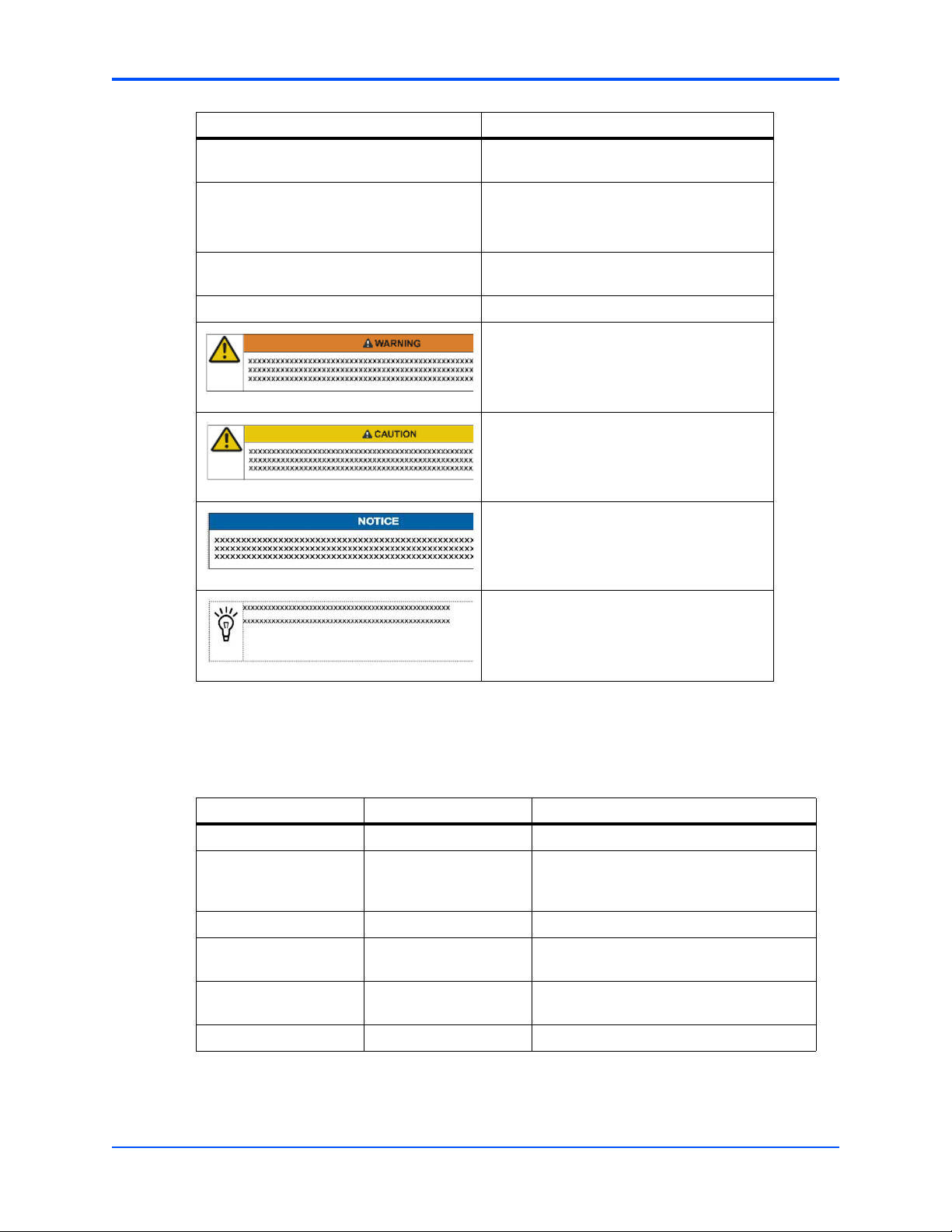
Conventions
The following table describes the conventions used throughout this manual.
Notation Description
0x00000000 Typical notation for hexadecimal numbers
0b0000 Same for binary numbers (digits are 0 and 1)
bold Used to emphasize a word
Screen Used for on-screen output and code related
Courier + Bold Used to characterize user input and to
Reference Used for references and for table and figure
(digits are 0 through F), for example used for
addresses and offsets
elements or commands in body text
separate it from system output
descriptions
10
File > Exit Notation for selecting a submenu
<text> Notation for variables and keys
[text] Notation for software buttons to click on the
screen and parameter description
RTM-ATCA-7350 Installation and Use (6806800H30F)
Page 11
About this Manual
Notation Description
... Repeated item for example node 1, node 2,
..., node 12
.
.
.
.. Ranges, for example: 0..4 means one of the
| Logical OR
Omission of information from
example/command that is not necessary at
the time being
integers 0,1,2,3, and 4 (used in registers)
Indicates a hazardous situation which, if not
avoided, could result in death or serious
injury
Indicates a hazardous situation which, if not
avoided, may result in minor or moderate
injury
Summary of Changes
This manual has been revised and replaces all prior editions.
Part Number Publication Date Description
6806800H30A March 2008 First edition
6806800H30B August 2008 Added Backplane Connectors (zone 3) to
6806800H30C January 2009 Third edition
6806800H30D November 2009 Updated Section Installing RTM-ATCA-
6806800H30E November 2009 Updated Section Installing RTM-ATCA-
6806800H30F February 2010 Updated Standard Compliances on page 14
Indicates a property damage message
No danger encountered. Pay attention to
important information
Chapter 3, Controls, LEDs and Connectors,
on page 37.
7350 on page 30.
7350 on page 30.
RTM-ATCA-7350 Installation and Use (6806800H30F)
11
Page 12

About this Manual
Comments and Suggestions
We welcome and appreciate your comments on our documentation. We want to know what you
think about our manuals and how we can make them better.
Mail comments to us by filling out the following online form:
http://www.emersonnetworkpowerembeddedcomputing.com/ > Contact Us > Online Form
In "Area of Interest" select "Technical Documentation". Be sure to include the title, part number,
and revision of the manual and tell us how you used it.
12
RTM-ATCA-7350 Installation and Use (6806800H30F)
Page 13
Introduction
1.1 Overview of RTM-ATCA-7350
The ATCA-7350 Rear Transition Module (RTM) of the server blade (hereinafter referred to as
RTM-ATCA-7350) must work with the server blade ATCA-7350. RTM-ATCA-7350 provides
external interfaces for the connected server blade.
RTM-ATCA-7350 provides the following functions:
z RTM-ATCA-7350 provides two daughter card connectors. RTM-ATCA-7350 supports the
following daughter cards:
– Gigabit Ethernet (GE) daughter card
– Fiber Channel (FC) daughter card
The daughter cards provide external interfaces for the server blade.
1
z As a manageable module of the server blade, RTM-ATCA-7350 is managed by the
Intelligent Platform Management Controller (IPMC) of the server blade.
z The IPMC monitors the working status of RTM-ATCA-7350. In addition, the Field
Replaceable Unit (FRU) data is stored in the EEPROMs on the RTM itself and the daughter
cards.
1.2 Mechanical Data
The following table lists the mechanical specifications of RTM-ATCA-7350.
Table 1-1 Mechanical Specifications of RTM-ATCA-7350
Item Specification
Maximum weight 0.76 kg
Length x width x height 322.3 mm x 70 mm x 29 mm
RTM-ATCA-7350 Installation and Use (6806800H30F)
13
Page 14
Introduction Standard Compliances
1.3 Standard Compliances
The product is designed to meet the following standards.
Table 1-2 Standard Compliances
Standard Description
UL 60950-1
EN 60950-1
IEC 60950-1
CAN/CSA C22.2 No 60950-1
CISPR 22
CISPR 24
EN 55022
EN 55024
FCC Part 15
Industry Canada ICES-003
VCCI Japan
AS/NZS CISPR 22
EN 300 386
NEBS Standard GR-1089 CORE
Legal safety requirements
EMC requirements (legal) on system level (predefined
Emerson Network Power Embedded Computing system)
NEBS Standard GR-63-CORE
ETSI EN 300019 series
1
PICMG
1. Some PICMG requirements are not fully met. Refer ATCA-7350/RTM-ATCA-7350 Release Notes for more
information.
3.0
1.4 Ordering Information
When ordering board variants or board accessories, use the order numbers given on the
following pages.
1.4.1 Supported Board Models
The following table explains the product nomenclature used for the available board variants.
Table 1-3 Product Nomenclature
Order Number Description
RTM-ATCA-7350 RTM FOR THE ATCA-7350 BLADE WITH 10G FABRIC
SUPPORT (ROHS 5/6)
Environmental requirements
Defines mechanics, blade dimensions, power distribution,
power and data connectors, and system management
14
RTM-ATCA-7350-GE RTM FOR THE ATCA-7350 BLADE WITH 2 GE INTERFACES
(ROHS 5/6)
RTM-ATCA-7350 Installation and Use (6806800H30F)
Page 15
Board Accessories Introduction
Table 1-3 Product Nomenclature (continued)
Order Number Description
RTM-ATCA-7350-2GE RTM FOR THE ATCA-7350 BLADE WITH 4 GE INTERFACES
(ROHS 5/6)
RTM-ATCA-7350-FC RTM FOR THE ATCA-7350 BLADE WITH 2 FC INTERFACES
(ROHS 5/6)
1.4.2 Board Accessories
As of the printing date of this manual, the following board accessories were available.
Table 1-4 Available Board Accessories
Board Accessories Order Number
Gigabit Ethernet (GE) daughter card MEZC-RTM-7150-GE
Fiber Channel (FC) daughter card
1
MEZC-RTM-7150-FC
1. Optical modules for the FC daughter card must be obtained separately. Recommended modules are:
FINISAR FTRJ8519P1BNL-HW
FINISAR FTRJ8519P2BNL-HW
RTM-ATCA-7350 Installation and Use (6806800H30F)
15
Page 16

Introduction Board Accessories
16
RTM-ATCA-7350 Installation and Use (6806800H30F)
Page 17

Hardware Preparation and Installation
2.1 Overview
This chapter describes:
z Unpacking and inspecting RTM-ATCA-7350
z Precautions during the operation
z Preparations before installation
z Installation procedure
z Installing and replacing daughter cards
z Connection of external cables
2
z Removal procedure
2.2 Unpacking and Inspecting RTM-ATCA-7350
Damage of Circuits
Electrostatic discharge and incorrect installation and removal of the product can
damage circuits or shorten their life.
Before touching the product or electronic components, make sure that your are
working in an ESD-safe environment.
Shipment Inspection
To inspect the shipment, perform the following steps.
1. Verify that you have received all items of your shipment:
Printed "Getting Started" guide
RTM-ATCA-7350
Any optional items ordered
2. Check for damage and report any damage or differences to the customer service.
RTM-ATCA-7350 Installation and Use (6806800H30F)
17
Page 18
Hardware Preparation and Installation Environmental and Power Requirements
3. Remove the desiccant bag shipped together with the blade and dispose of it
according to your country’s legislation.
The product is thoroughly inspected before shipment. If any damage occurred during
transportation or any items are missing, please contact our customer's service
immediately.
2.3 Environmental and Power Requirements
The following environmental and power requirements are applicable to the board.
2.3.1 Environmental Requirements
Table 2-1 Environmental Requirements
Requirement Operating Non-Operating
Temperature +5ºC (41ºF) to +40ºC (104ºF) (normal operation)
according to NEBS Standard GR-63-CORE
-5ºC to +55ºC (short term operation) according to
NEBS Standard GR-63-CORE
Temp. Change +/- 0.25ºC/min or 15ºC/h (59ºF/h) according to
NEBS Standard GR-63-CORE
Rel. Humidity 5% to 85% non-condensing according to Emerson
Network Power Embedded Computing-internal
environmental requirements
Altitude <= 4000m
Vibration 1.0g from 5 to 100 Hz and back to 5 Hz at a rate
of 0.1 octave/minute
Shock Half-sine, 11 m/Sec, 30mSec/sec
2
-40ºC (-40ºF) to +70ºC
(158ºF) (may be further
limited by installed
accessories)
+/- 0.25ºC/min or 15ºC/h
(59ºF/h)
5% to 85% non-condensing
according to Emerson
Network Power Embedded
Computing-internal
environmental
requirements
5-20 Hz @ 0.01 g
20-200 Hz @ -3.0
dB/octave
Random 5-20 Hz @ 1
3
m2/Sec
Random 20-200 Hz @ -3
2
m/Sec
Blade level packaging
Half-sine, 6 mSec at 180
2
m/Sec
2
/Hz
18
RTM-ATCA-7350 Installation and Use (6806800H30F)
Page 19

Power Requirements Hardware Preparation and Installation
Table 2-1 Environmental Requirements (continued)
Requirement Operating Non-Operating
Free Fall 1,200 mm (Packaged) /all
edges and corners
1.0m (Packaged) per ETSI
300 019-2-2 (Blade level
packaging)
25mm (unpackaged) per
GR-63-CORE
2.3.2 Power Requirements
Table 2-2 Power Requirements
Requirement Operating
Power supply Provided by the server blade
Maximum power consumption 14.2 W
2.4 Module Installation and Removal
Personal Injury
Power and communication cables
Touching power and communication cables that are energized may cause injuries.
Make sure that the cables cannot be touched while the product is operating.
Damage of Circuits
Electrostatic discharge and incorrect installation and removal of the product can
damage circuits or shorten their life.
Before touching the product or electronic components, make sure that your are
working in an ESD-safe environment.
RTM-ATCA-7350 Installation and Use (6806800H30F)
19
Page 20

Hardware Preparation and Installation Ejector Handles
Module Damage
If the blade is not fully aligned with the interface in the backplane, too much force may
twist the pins on the blade or backplane.
Do not exert too much force when you insert the blade.
Note the following points at the time of installing RTM-ATCA-7350:
z Make sure that you wear an electrostatic discharge (ESD)-preventive wrist strap to prevent
the static electricity from hurting you or damaging the device.
z Keep your personal objects such as your clothes away from RTM-ATCA-7350. To prevent
the static electricity on clothing, you need to put on antistatic clothing.
z RTM-ATCA-7350 is installed in the slot paired with the server blade slot at the back side of
the shelf. RTM-ATCA-7350 is powered from the payload power of the front board. You
should install RTM-ATCA-7350 before payload power of the front board is turned on. Hot
swap of the RTM-ATCA-7350 while under power is not supported.
z Hold the ejector handles and the face plate when you insert or remove RTM-ATCA-7350.
Do not touch the components inside of the blades.
z Keep the blade vertical when you install RTM-ATCA-7350. Align the blade with the slot and
then insert it in the shelf.
2.4.1 Ejector Handles
RTM-ATCA-7350 is powered by the server blade in the slot paired with the RTM-ATCA-7350
slot. RTM-ATCA-7350 does not support hot swap. As shown in Figure 1-4, the face plate of
RTM-ATCA-7350 provides an upper and a lower ejector handles. The ejector handles help to
insert, remove, fasten, power on, and power off RTM-ATCA-7350.
2.4.2 ESD Prevention
Static electricity may hurt you or damage the device. To minimize the damage, pay attention to
the following points:
z Before you operate the device, wear the ESD-preventive wrist strap. Both terminals of the
ESD-preventive wrist strap must contact well. One terminal touches your bare skin, and the
other is inserted in the jack at the front or back side of the shelf. For details on how to wear
the ESD-preventive wrist strap, refer Wearing the ESD-Preventive Wrist Strap on page 21.
z Avoid moving your body as much as possible. Movement gathers static electricity around
you.
20
z Do not touch the solder point, pin, or bare circuit.
z Do not leave the device in the place where others can operate it.
RTM-ATCA-7350 Installation and Use (6806800H30F)
Page 21

Installation Preparations Hardware Preparation and Installation
z Install the device at once after you take it out of the antistatic package. If you need to lay
down the device, place it back in the antistatic package. Do not lay the device on the shelf
or cabinet.
z Monitor the temperature and humidity of the equipment room. Warm air decreases the
humidity and increases the static electricity in the room.
2.5 Installation Preparations
The installation preparations process includes:
z check the installation environment
z wear the ESD-preventive wrist strap
z remove the blank filler panels
z unpack and check the RTM-ATCA-7350 suite
2.5.1 Wearing the ESD-Preventive Wrist Strap
Module Damage
z Electrostatic discharge can damage circuits or shorten their life.
z The ESD-preventive wrist strap prevents only the static electricity on your body
from damaging the blade. To prevent the static electricity on your clothes, it is
recommended to wear the antistatic clothes. Additionally, you have to make sure
that the cabinet and shelf are properly grounded - for details, refer to the
corresponding system documentation.
RTM-ATCA-7350 Installation and Use (6806800H30F)
21
Page 22

Hardware Preparation and Installation Wearing the ESD-Preventive Wrist Strap
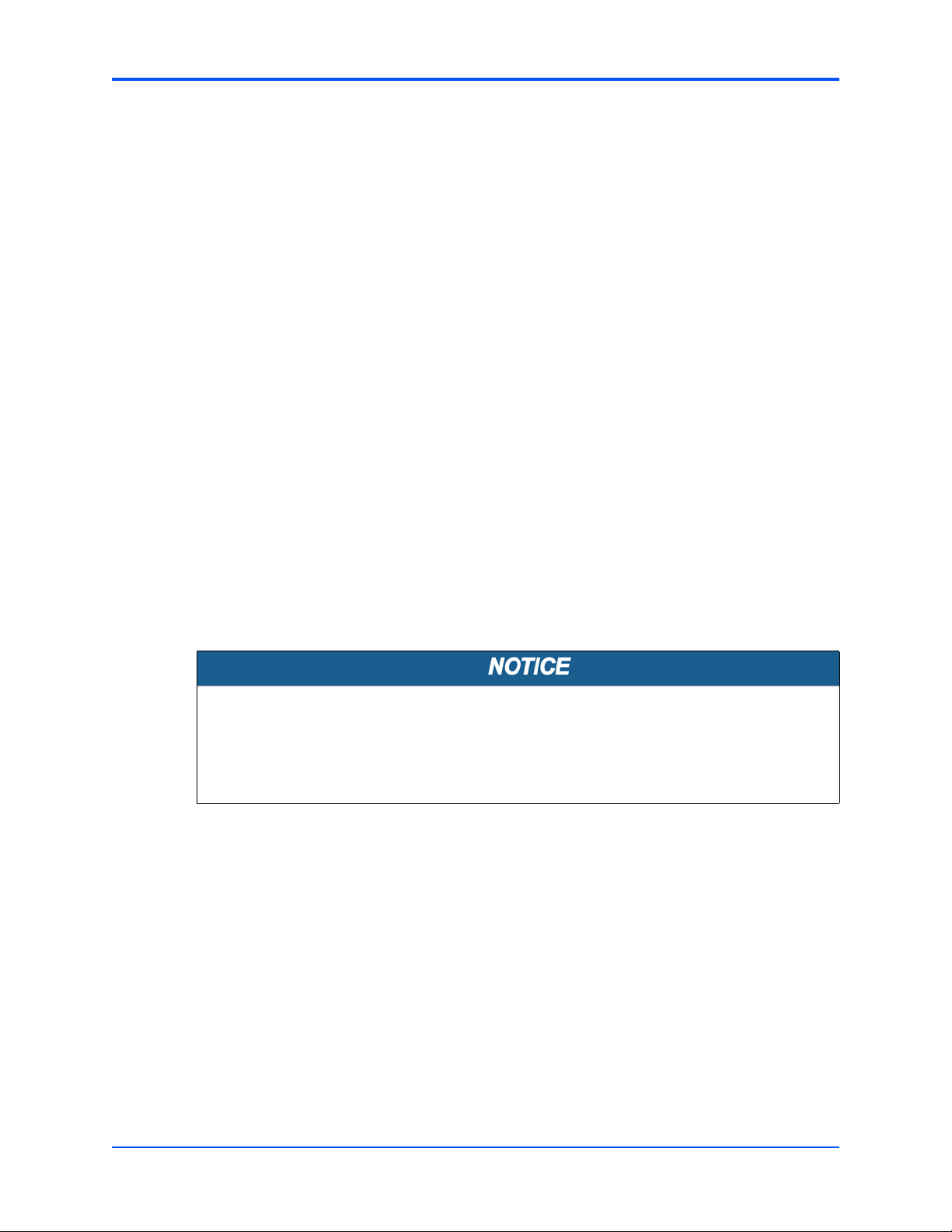
To wear the ESD-preventive wrist strap, proceed as follows:
1. Wrap the ESD-preventive wrist strap around your wrist, as shown in the figure
below.
2. Fasten the latch. Make sure that the ESD-preventive wrist strap well touches your
bare wrist.
3. Insert the grounding terminal of the ESD-preventive wrist strap in the jack of the
cabinet or shelf.
Figure 2-1 Wearing the ESD-Preventive Wrist Strap
22
RTM-ATCA-7350 Installation and Use (6806800H30F)
Page 23

1
1
2
Removing Filler Blades Hardware Preparation and Installation
2.5.2 Removing Filler Blades
After a filler blade is removed, place it in the equipment room or other moisture-proof
and dust-proof places.
You should install a blank filler blade in the slot after removing the blade. Otherwise, it
may effect the ventilation, heat dissipation, electromagnetic shielding and dust
prevention of the shelf.
If this is the first installation for the shelf, the blade is fully configured and the shelf is
not powered on, you can remove all the filler blades. Then, install blades in the slots in
order. This document takes the first installation as an example.
If you want to install multiple blades in the shelf that is powered on, you can remove a
filler blade and then install a blade one by one.
If the slot is occupied with a filler blade you have to remove it first.
To remove the filler blade, proceed as follows:
1. As shown in step 1 of the figure below, use a screwdriver to anticlockwise loosen
the two captive screws on a filler blade.
2. As shown in step 2 of the figure below, remove the filler blade.
Figure 2-2 Removing the Filler Blade
RTM-ATCA-7350 Installation and Use (6806800H30F)
23
Page 24

Hardware Preparation and Installation Installing and Replacing Daughter Cards
2.6 Installing and Replacing Daughter Cards
2.6.1 Precautions
Incorrect installation or removal of additional devices or modules may damage the
product or the additional devices or modules.
Before installing or removing additional devices or modules, read the respective
documentation.
Personal Injury
Power and communication cables
Touching power and communication cables that are energized may cause injuries.
Make sure that the cables cannot be touched while the product is operating.
Electrostatic discharge and incorrect installation and removal of the product can
damage circuits or shorten their life.
Before touching the product or electronic components, make sure that your are
working in an ESD-safe environment.
Do not exert too much force when you insert the blade.
If the blade is not fully aligned with the interface in the backplane, too much force may
twist the pins on the blade or backplane.
Note the following points at the time of installing or replacing components:
24
z Make sure that you wear an electrostatic discharge (ESD)-preventive wrist strap to prevent
the static electricity from hurting you or damaging the device.
z Keep the area where the components reside clean and keep the components away from
the heat-generating devices, such as radiators.
RTM-ATCA-7350 Installation and Use (6806800H30F)
Page 25

Preparations Hardware Preparation and Installation
z Ensure that your sleeves are tightened or rolled up above the elbow. For safety purpose, it
is not recommended to wear jewelry, watch, glasses with metal frame, or clothes with metal
buttons.
z Do not exert too much force, or insert or remove the components forcibly. Avoid damage
to the components or plug-ins, for example, the pins are bent or get short circuit.
2.6.2 Preparations
Before you install or replace a component, make the following preparations
z Confirming the feasibility of the operation
– There are available spare parts of the component to be installed or replaced in the
equipment warehouse. When the available spare parts are in short supply, contact
Emerson Network Power Embedded Computing for help in time.
– Make sure that the new component is in good condition, without defects such as
oxidation, chemical corrosion, missing component, or transportation damage.
– By reading this document, you are familiar with how to install and replace the
component and master the skills required by the operation.
z Checking the environment
Make sure that the shelf, power supply, temperature, and humidity meet the operating
requirements of the blades and components. For details, refer to ATCA-7350 Installation
and Use Manual and other related documents.
z Preparing spare parts and tools
– Prepare the component to be installed or replaced.
When you hold or transport the component, use the special antistatic package. In
addition, you need to tidy, record, and repair the component during routine
maintenance.
– Prepare the cross screwdriver, screws, plastic supports, cooling gel, and ESD-
preventive wrist strap.
The supplier provides a list of tools and negotiates with you to decide the tool provider.
z Confirming installation or changing positions
Confirm the positions of the cabinet, the shelf, and the slot where RTM-ATCA-7350 is
installed. Then, stick a label on the face plate of RTM-ATCA-7350 to avoid wrong operation.
z Others
If a serious problem occurs and cannot be solved when you install or replace the
component, contact Emerson Network Power Embedded Computing for technical support.
2.6.3 GE Daughter Card
This manual considers the GE daughter card providing two external Ethernet interfaces as an
example, and describes how to install the daughter card on and remove it from RTM-ATCA-
7350.
RTM-ATCA-7350 Installation and Use (6806800H30F)
25
Page 26
J2
J1
1
2
Hardware Preparation and Installation GE Daughter Card
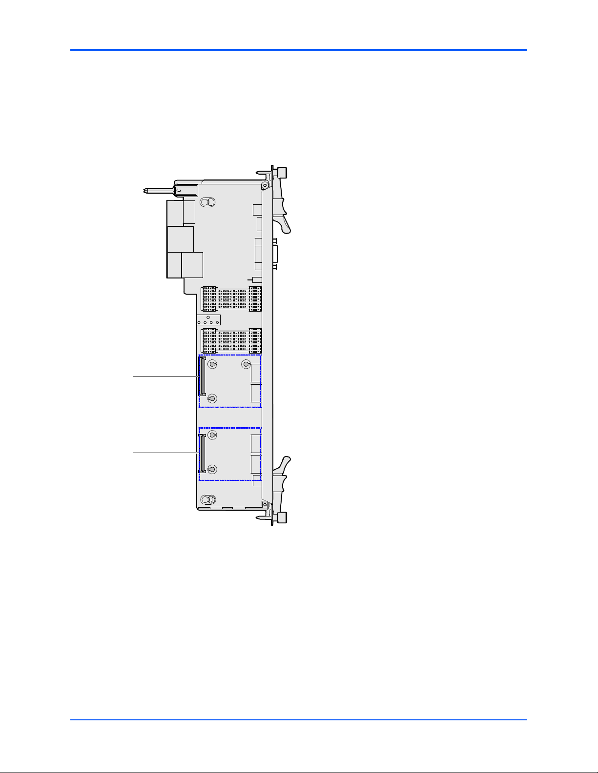
2.6.3.1 Installation Positions
When the GE daughter card is used with the RTM-ATCA-7350 it can be installed on the
daughter card connector J1, J2. The default position as used on the RTM-ATCA-7350-GE is
position J2.
Figure 2-3 Structure of RTM-ATCA-7350
2.6.3.2 Installing the GE Daughter Card
To install the GE daughter card, proceed as follows.
26
1. Wear the ESD-preventive wrist strap. For more information refer, Wearing the ESD-
Preventive Wrist Strap on page 21.
2. Lay RTM-ATCA-7350 where the GE daughter card is to be installed on the antistatic
desktop.
RTM-ATCA-7350 Installation and Use (6806800H30F)
Page 27
1
2
3
GE Daughter Card Hardware Preparation and Installation
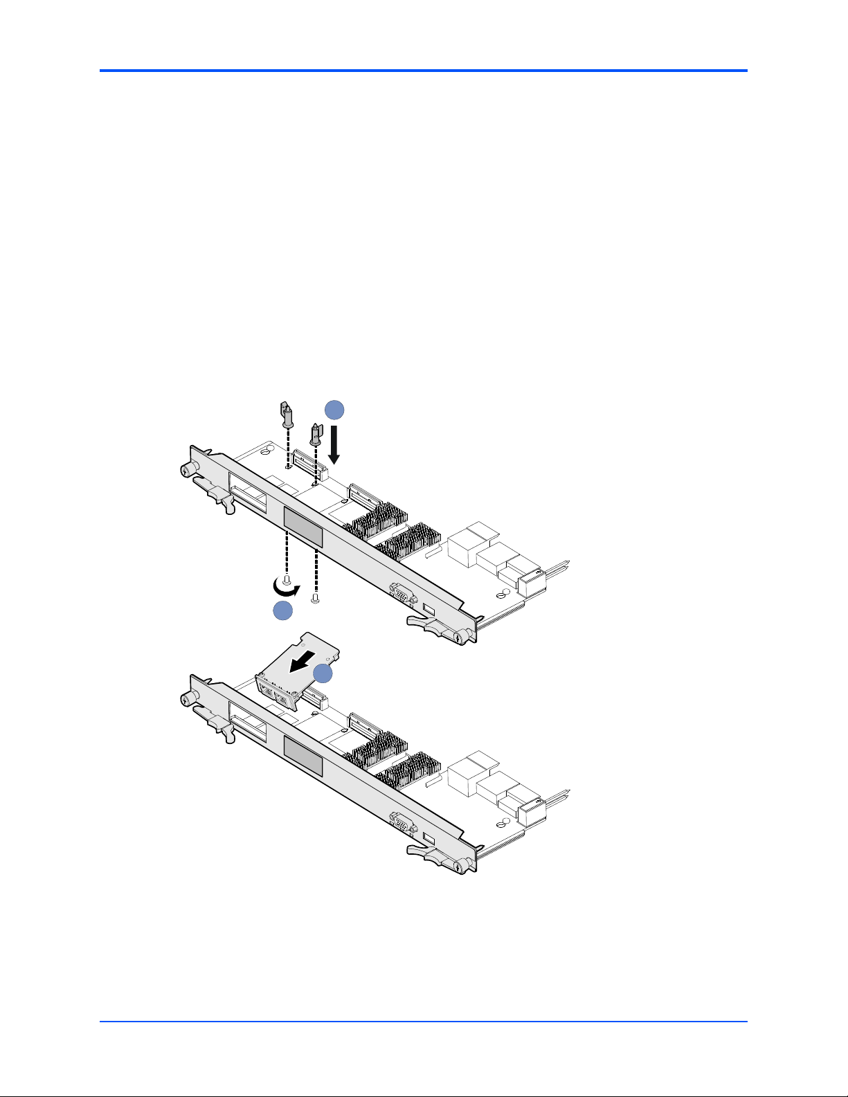
3. As shown in step 1 of the figure below, insert two plastic supports vertically in the
holes used to fasten the GE daughter card.
4. As shown in step 2 of the figure below, at the back side of RTM-ATCA-7350, use a
screwdriver to clockwise fasten the two screws used to fix the plastic supports.
5. Take the GE daughter card out of the antistatic package.
6. Insert the GE daughter card in RTM-ATCA-7350 by facing the daughter card at an
angle of 45° to the RTM. Align the daughter card connector with the connector on
RTM-ATCA-7350, and the daughter card positioning holes with the plastic supports
on RTM-ATCA-7350. Exert even power downwards until the daughter card
connector is fully inserted into the connector on RTM-ATCA-7350 and the daughter
card is fastened by the plastic latches. See step 3 in the figure below.
Figure 2-4 Installing the GE Daughter Card
7. Insert
information refer, Installing RTM-ATCA-7350 on page 30.
RTM-ATCA-7350 with the GE daughter card installed in the shelf. For more
RTM-ATCA-7350 Installation and Use (6806800H30F)
27
Page 28

Hardware Preparation and Installation FC Daughter Card
After installation, check if RTM-ATCA-7350 can be powered on and work normally. Use the
network cable to connect RTM-ATCA-7350 to the external network. Check if the network is
connected properly and monitor whether the network port indicator is normal.
2.6.3.3 Replacing the GE Daughter Card
To replace the GE daughter card, proceed as follows.
1. Wear the ESD-preventive wrist strap. For more information refer, Wearing the ESD-
Preventive Wrist Strap on page 21.
2. Remove the
RTM-ATCA-7350 whose GE daughter card is to be replaced. For more
information refer, Removing RTM-ATCA-7350 on page 32.
3. Open the plastic latches fastening the GE daughter card.
4. Exert even force upwards until the daughter card connector is removed from the
connector on RTM-ATCA-7350. Remove the daughter card by facing the daughter
card at an angle of 45° to the RTM.
5. Place the removed GE daughter card in an antistatic package.
6. Take the new GE daughter card out of the antistatic package.
7. Insert the GE daughter card in RTM-ATCA-7350 by facing the daughter card at an
angle of 45° to the RTM. Align the daughter card connector with the connector on
RTM-ATCA-7350, and the daughter card positioning holes with the plastic supports
on RTM-ATCA-7350. Exert even power downwards until the daughter card
connector is fully inserted into the connector on RTM-ATCA-7350 and the daughter
card is fastened by the plastic latches.
8. Install
RTM-ATCA-7350 whose GE daughter card is replaced. For more information
refer, Installing RTM-ATCA-7350 on page 30.
After replacement, check if RTM-ATCA-7350 can be powered on and work normally. Use the
network cable to connect RTM-ATCA-7350 to the external network. Check if the network is
connected properly and monitor whether the network port indicator is normal.
2.6.4 FC Daughter Card
This section describes how to install the daughter card on and remove it from RTM-ATCA-7350.
2.6.4.1 Installation Positions
When the FC daughter card is used with the RTM-ATCA-7350 it can be installed on the
daughter card connector J1. The RTM-ATCA-7350 provides space for one FC daughter card.
Use of the FC daughter card excludes use of the GE daughter card.
28
RTM-ATCA-7350 Installation and Use (6806800H30F)
Page 29

FC Daughter Card Hardware Preparation and Installation
2.6.4.2 Installing the FC Daughter Card
To install the FC daughter card, proceed as follows.
1. Wear the ESD-preventive wrist strap. For more information refer, Wearing the ESD-
Preventive Wrist Strap on page 21.
2. Lay RTM-ATCA-7350 where the FC daughter card is to be installed on the antistatic
desktop.
3. Insert two plastic supports vertically in the holes used to fasten the FC daughter
card.
4. At the back side of RTM-ATCA-7350, use a screwdriver to clockwise fasten the two
screws used to fix the plastic supports.
5. Take the FC daughter card out of the antistatic package.
6. Insert the FC daughter card in RTM-ATCA-7350 by facing the daughter card at an
angle of 45° to the RTM. Align the daughter card connector with the connector on
RTM-ATCA-7350, and the daughter card positioning holes with the plastic supports
on RTM-ATCA-7350. Exert even power downwards until the daughter card
connector is fully inserted into the connector on RTM-ATCA-7350 and the daughter
card is fastened by the plastic latches.
7. Insert
RTM-ATCA-7350 with the FC daughter card installed in the shelf. For more
information refer, Installing RTM-ATCA-7350 on page 30.
After installation, check if RTM-ATCA-7350 can be powered on and work normally. Use the
optical fiber to connect RTM-ATCA-7350 to the external storage system. Check if RTM-ATCA7350 can transmit data normally and monitor whether the FC status indicator is normal.
2.6.4.3 Replacing the FC Daughter Card
To replace the FC daughter card, proceed as follows.
1. Wear the ESD-preventive wrist strap. For more information refer, Wearing the ESD-
Preventive Wrist Strap on page 21.
2. Remove the
RTM-ATCA-7350 whose FC daughter card is to be replaced. For more
information refer, Removing RTM-ATCA-7350 on page 32.
3. As shown in step 1 of the figure below, open the plastic latches fastening the FC
daughter card.
4. Exert even force upwards until the daughter card connector is removed from the
connector on RTM-ATCA-7350. As shown in step 2 of the figure below, remove the
daughter card by facing the daughter card at an angle of 45° to the RTM.
RTM-ATCA-7350 Installation and Use (6806800H30F)
29
Page 30
Hardware Preparation and Installation Installing and Removing the RTM-ATCA-7350
5. Place the removed FC daughter card in an antistatic package.
6. Take the new FC daughter card out of the antistatic package.
7. Insert the FC daughter card in RTM-ATCA-7350 by facing the daughter card at an
angle of 45° to the RTM. Align the daughter card connector with the connector on
RTM-ATCA-7350, and the daughter card positioning holes with the plastic supports
on RTM-ATCA-7350. Exert even power downwards until the daughter card
connector is fully inserted into the connector on RTM-ATCA-7350 and the daughter
card is fastened by the plastic latches. See step 3 in the figure above.
8. Install
RTM-ATCA-7350 whose FC daughter card is replaced. For more information
refer, Installing RTM-ATCA-7350 on page 30.
After replacement, check if RTM-ATCA-7350 can be powered on and work normally. Use the
optical fibre to connect RTM-ATCA-7350 to the external storage system. Check if RTM-ATCA7350 can transmit data normally and monitor whether the FC status indicator is normal.
2.7 Installing and Removing the RTM-ATCA-7350
2.7.1 Installing RTM-ATCA-7350
Product Damage
You can install RTM-ATCA-7350 into a system if the front blade is already installed or
if it is not installed. In case the front blade is already installed, its payload has to be
powered down first.
30
Installation Procedure with Installed Front Blade
The following procedure describes the installation of RTM-ATCA-7350. It assumes that your
system is powered on. If your system is powered off, you can disregard the blue LED and thus
skip the respective step. In this case it is a purely mechanical installation. The same applies to
an installation without an installed front blade. In this case disregard the LEDs and skip the
respective step.
1. Wear the ESD-preventive wrist strap. For more information refer, Wearing the ESD-
Preventive Wrist Strap on page 21.
2. Unlatch the lower handle of the front blade outward by squeezing the lever and the
latch together and turning the handle outward only enough to unlatch the handle
from the face plate, that means until you feel a resistance. Do not rotate the handle
fully outward.
RTM-ATCA-7350 Installation and Use (6806800H30F)
Page 31
Installing RTM-ATCA-7350 Hardware Preparation and Installation
The blue LED blinks indicating that the shelf manager is informed about the desire
of the blade to power down the payload of the front blade and the power-down
process is ongoing.
3. Wait until the blue LED of the front blade is permanently ON. A permanently
switched ON LED indicates that the payload of the front blade has been powered
down.
4. Remove the front blade. For instructions on how to remove the blade, refer to
Section 2.7.2.2 Removing the ATCA-7350 in ATCA-7350 Installation and Use
manual.
5. Take RTM-ATCA-7350 out of the antistatic package.
6. Fully open the upper and lower ejector handles of the RTM.
7. Align the upper and lower sides of RTM-ATCA-7350 with the guide rails (the edges
of the slot). Slide RTM-ATCA-7350 along the guide rails until the positioning pins of
RTM-ATCA-7350 are inserted in the positioning holes in the shelf.
Figure 2-5 Installing RTM-ATCA-7350
8. Make sure that the ejector handles are fastened to the beam. Close the upper and
lower ejector handles inwards until the inner sides of the ejector handles are
attached to the face plate.
9. Use the screwdriver to fasten the captive screws clockwise to fix RTM-ATCA-7350.
The LEDs of the RTM are off now.
RTM-ATCA-7350 Installation and Use (6806800H30F)
31
Page 32

Hardware Preparation and Installation Removing RTM-ATCA-7350
10.Insert the main blade. For instructions on how to install the main blade, refer to
Section 2.7.1.1 Installing the ATCA-7350 in a Powered Shelf in ATCA-7350
Installation and Use manual.
11.Close the handles of the front blades. The LEDs; OOS LED, Blue LED, and healthy
LED of RTM are on.
12.Wait until the blue LED on the RTM is OFF.
A switched off blue LED indicates that the payload of the RTM has become active.
2.7.2 Removing RTM-ATCA-7350
Product Damage
You should power off the front blade before removing RTM-ATCA-7350.
To remove RTM-ATCA-7350, proceed as follows:
1. Wear the ESD-preventive wrist strap. For more information refer, Wearing the ESD-
Preventive Wrist Strap on page 21.
2. Unlatch the lower handle outward by squeezing the lever and the latch together and
turning the handle outward only enough to unlatch the handle from the face plate,
that means until you feel a resistance. Do not rotate the handle fully outward.
The blue LED blinks indicating that the shelf manager is informed about the desire
of the blade to power down the payload of both the front blade and the RTM and the
power-down process in ongoing.
3. Wait until the blue LED of the RTM is permanently ON. A permanently switched ON
LED indicates that the payload of the RTM has been powered down.
4. As shown in step 2 of the figure below, use the screwdriver to unfasten the captive
screws of the RTM anticlockwise.
5. As shown in step 1 of the figure below, fully open the upper and lower ejector
handles.
32
RTM-ATCA-7350 Installation and Use (6806800H30F)
Page 33

1
1
2
2
3
Connecting External Cables Hardware Preparation and Installation
6. As shown in step 3 of the figure below, remove RTM-ATCA-7350 along the guide
rails.
7. Place RTM-ATCA-7350 in the antistatic package.
Figure 2-6 Removing RTM-ATCA-7350
2.8 Connecting External Cables
After RTM-ATCA-7350 is installed in the shelf, you can connect the keyboard, video, and mouse
(KVM) cables.
If RTM-ATCA-7350 is configured with the GE daughter card or FC daughter card, it provides the
external GE network ports or external FC interfaces. Network cables or optical fibers can be
connected to RTM-ATCA-7350. You can choose to use one or more daughter cards according
to actual applications.
Refer Daughter Cards on page 47, for the functions of the daughter cards of RTM-ATCA-
7350.
RTM-ATCA-7350 Installation and Use (6806800H30F)
33
Page 34

Hardware Preparation and Installation Connecting KVM Cables
Cable Damage
z There is a back cable trough at the back side of the shelf. You need to arrange and
identify all cables and then bind and fasten them in the back cable through after
connecting them.
z If you use excessive force when installing cables, the cables may be damaged.
z Do not exert too much force when you insert or remove the cables. Do not twist
or tear the cables in any condition.
2.8.1 Connecting KVM Cables
The figure below shows the method of connecting the Keyboard, Video, Mouse (KVM) cables
to RTM-ATCA-7350 when connecting PS/2 compatible keyboard and mouse using a PS/2-USB
converter. USB based keyboard and mouse can also be attached to the RTM by using a USB
hub.
Product Damage
You have to use matching interfaces for the KVM cables.
Use a PS/2-USB converter when connecting to PS/2 based keyboard and mouse
cables.
Use a USB hub when connecting to USB based keyboard and mouse cables.
Figure 2-7 Connecting the KVM Cables to RTM-ATCA-7350
34
RTM-ATCA-7350 Installation and Use (6806800H30F)
Page 35

Connecting Network Cables Hardware Preparation and Installation
2.8.2 Connecting Network Cables
Electromagnetic Radiation
Make sure that the cable and connectors of the network cable are with shielding
function and that both ends of the shielded layer of the network cable are grounded.
It is recommended that the network cable is grounded through the metal cover of the
network port connector.
When RTM-ATCA-7350 is configured with the GE daughter card, it provides two external
Ethernet interfaces with 10/100/1000M Base-T auto-negotiation. Network cables are used to
connect RTM-ATCA-7350 to the external network.
The figure below shows the method of connecting the network cables to RTM-ATCA-7350.
Figure 2-8 Connecting the Network Cables to RTM-ATCA-7350
RTM-ATCA-7350 Installation and Use (6806800H30F)
35
Page 36

2
1
Hardware Preparation and Installation Connecting Optical Fibers
2.8.3 Connecting Optical Fibers
When RTM-ATCA-7350 is configured with the FC daughter card, it provides two external 2G FC
interfaces. Optical fibers are used to connect RTM-ATCA-7350 to the external Storage Area
Network (SAN) storage system. Optical modules for the FC daughter cards must be obtained
separately. Recommended modules are FINISAR FTRJ8519P1BNL-HW, FINISAR
FTRJ8519P2BNL-HW.
As shown in steps 1 and 2 in the figure below, insert the optical module in the FC interface and
then insert the optical fibers in the optical module.
Figure 2-9 Connecting the Optical Fibers to RTM-ATCA-7350
36
RTM-ATCA-7350 Installation and Use (6806800H30F)
Page 37

Controls, LEDs and Connectors
3.1 Overview
This chapter describes:
z Face plate connectors
z Face plate LEDs
z Rear panel connectors
3
RTM-ATCA-7350 Installation and Use (6806800H30F)
37
Page 38

OOS indicator
VGA interface
USB interface
H/S indicator
IS indicator
ATN indicator
Captive screw
Ejector handle
Filler panel
Filler panel
Controls, LEDs and Connectors Face Plate Connectors and LEDs
3.2 Face Plate Connectors and LEDs
The following figure shows the face plate of RTM-ATCA-7350 without daughter cards installed.
Figure 3-1 Face Plate of RTM-ATCA-7350
You need to install a filler blade in the position that is not occupied by the face plate of
the daughter card.
3.2.1 LEDs
The face plate of RTM-ATCA-7350 provides the following indicators:
z Out of service (OOS) indicator
z In service (IS) indicator
z Hotswap (H/S) indicator
38
RTM-ATCA-7350 Installation and Use (6806800H30F)
Page 39

LEDs Controls, LEDs and Connectors
The GE daughter card provides the network port indicators and the FC daughter card provides
the FC status indicators. You can monitor these indicators to diagnose the current status of
RTM-ATCA-7350.
The following table lists the indicators on the RTM-ATCA-7350 face plate.
Table 3-1 Indicators on the RTM-ATCA-7350 Fac e Plate
Indicator Color Meaning Description
OOS Red or amber Service status
indicator
IS Red, green or
amber
H/S Blue Hot swap indicator z Off: RTM-ATCA-7350 is in activated state.
In service indicator The IS LED is off when the payload processor
z The RTM-ATCA-7350 turns the red LED on
when transitioning from FRU M3 to M4
state if in local control state. It is the
responsibility of the application to change
the status of the LED via IPMI command.
z The RTM-ATCA-7350 turns the LED off
when transitioning from FRU state M6 to
M1 if in local control state.
starts running.
Payload Management software is
responsible for controlling the IS LED.
z On: RTM-ATCA-7350 is inserted, but in
deactivated state or not powered on.
1
z Blinking at the long blink rate
7350 is requesting activation.
z Blinking at the short blink rate2: RTM-
ATCA-7350 is requesting deactivation.
: RTM-ATCA-
ATN Amber Attention indicator The ATN LED is set to off when the payload
processor starts running.
Payload Management software is responsible
for controlling the ATN LED.
1. Blinking at the long blink rate means that the indicator is on for 900 ms and then off for 100 ms alternatively.
2. Blinking at the short blink rate means that the indicator is on for 100 ms and then off for 900 ms alternatively.
RTM-ATCA-7350 Installation and Use (6806800H30F)
39
Page 40

J2
J1
1
2
Controls, LEDs and Connectors Connectors
3.2.2 Connectors
RTM-ATCA-7350 provides two daughter card connectors, as shown in the following figure.
Figure 3-2 Structure of RTM-ATCA-7350
In the above figure:
Label Description
1 Daughter card connector J2
2 Daughter card connector J1
3.2.2.1 RTM-ATCA-7350 Face Plate
Face plate of the RTM-ATCA-7350 provides:
z One USB interface
z One VGA DB15 Port
40
RTM-ATCA-7350 Installation and Use (6806800H30F)
Page 41

OOS indicator
VGA interface
USB interface
H/S indicator
IS indicator
ATN indicator
Captive screw
Ejector handle
Filler panel
Filler panel
Connectors Controls, LEDs and Connectors
z OOS indicator
z IS indicator
z ATN indicator
z H/S indicator
Figure 3-3 Connectors and Indicators of RTM-ATCA-7350
RTM-ATCA-7350 Installation and Use (6806800H30F)
41
Page 42
Controls, LEDs and Connectors Connectors
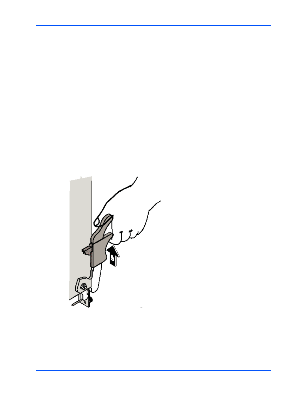
3.2.2.1.1 USB Port
RTM-ATCA-7350 provides a single port USB connector on the face plate. The USB port is
compliant to the USB 1.1 specification. The following USB Port Pin Assignment table describes
the pinout information.
Figure 3-4 RTM-ATCA-7350 Front Plate USB Connector Pinout
Table 3-2 USB Port Pin Assignment
Pin Pin Name Description
1 +5V +5V Power Supply, Max 500mA each port.
2 Data- Differential Data transmitting pair.
3 Data+
4 GROUND Ground, connected to the logic GND of ATCA-7350.
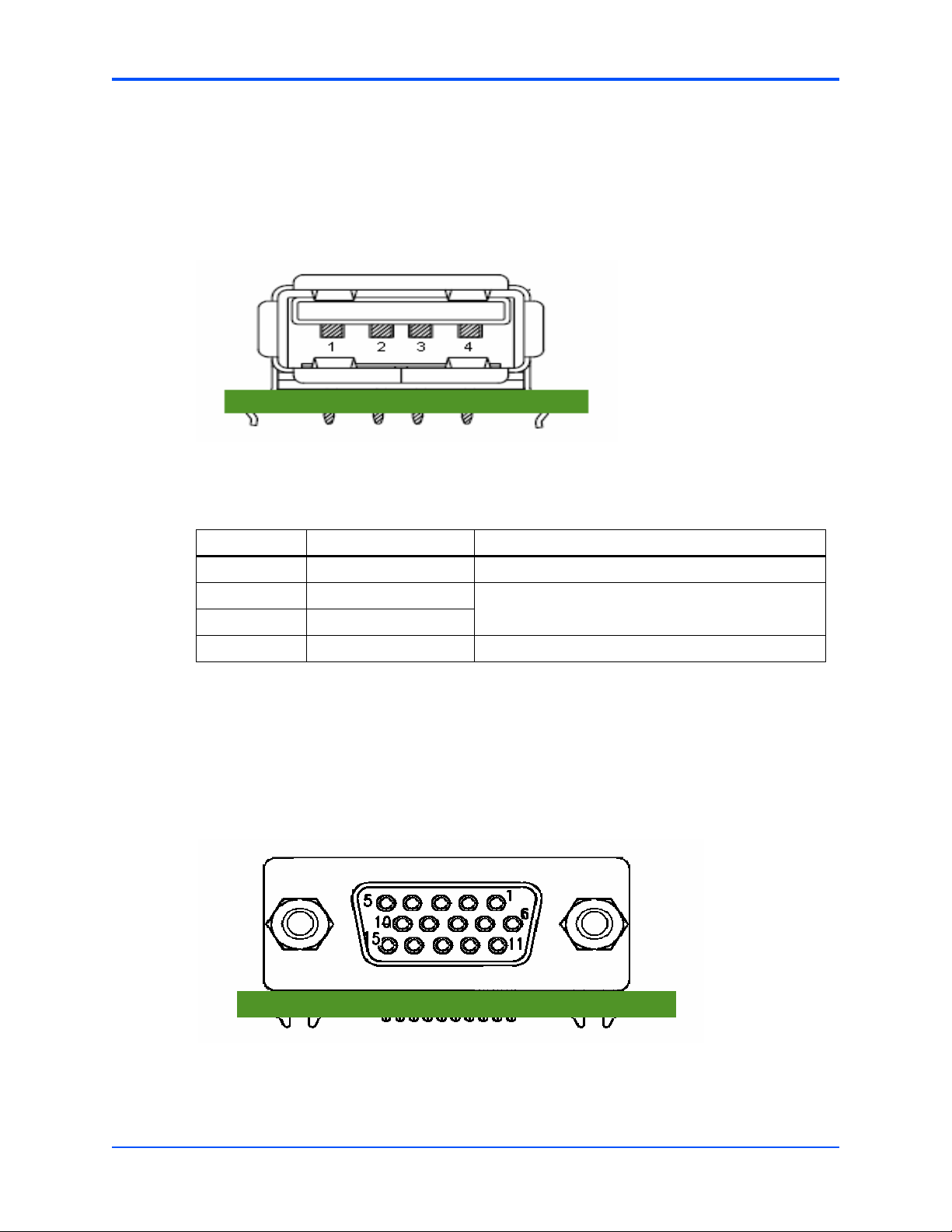
3.2.2.1.2 VGA Port
ATCA-7350 provides its VGA output port through RTM-ATCA-7350. The VGA port on RTMATCA-7350 use a DB15 female connector with a signal definition compatible to the standard
VGA plug.
Figure 3-5 RTM-ATCA-7350 Front Plate VGA Port Pinout
42
RTM-ATCA-7350 Installation and Use (6806800H30F)
Page 43

Zone 3 Connectors Controls, LEDs and Connectors
Table 3-3 VGA Port Pin Assignment
Pin Pin Name Description
1 RED Analog red video output signal.
2 GREEN Analog green video output signal.
3 BLUE Analog blue video output signal.
4 RESERVED1 Reserved.
5 RESERVED2 Reserved on RTM-ATCA-7350.
6 GROUND1 Connected to the logic ground of RTM-ATCA-7350.
7 GROUND2 Connected to the logic ground of RTM-ATCA-7350.
8 RESERVED3 Reserved on RTM-ATCA-7350.
9 RESERVED4 Reserved, Connected to 5VCC on RTM-ATCA-7350 through
a PTC resistor.
10 GROUND3 Connected to the logic ground of RTM-ATCA-7350.
11 RESERVED5 Reserved.
12 DDC DATA DDC data pin for CRT.
13 HS Horizontal sync for Monitor.
14 VS Vertical sync for Monitor.
15 DDC CLK DDC pin SCL for CRT.
3.3 Zone 3 Connectors
Zone 3 is composed of three connectors, P30, P31, and P32. The three connectors are used
to connect RTMs with RTM-ATCA-7350s. Zone 3 defines the following signals:
z USB (USB)
z VGA
z IPMC SMBus
z Power (VCC 12VDC, VSBY 5V5)
z PCI-E Channels
z General control signals (RTM PRESENT, RTM RST, LEDs)
z Fabric channel port 0, port 1, port 2, port 3 for the ATCA-7350
3.3.1 P30 Pinout
P30 uses a common 2mm HM connector. P31 uses a half-height ZD connector. P32 uses a ZD
connector.
Refer to the PICMG specification for the location of the connectors.
The following table shows the P30 pinout. PinA1 on the server blade side is on the top of the
connector while the server blade is placed top side upwards and the face plate is left.
RTM-ATCA-7350 Installation and Use (6806800H30F)
43
Page 44

Controls, LEDs and Connectors P31 Pinout
RTM_EN0_ and RTM_EN_ are signals that indicate the RTM is firmly inserted.
Table 3-4 PIN 30 Pinout
HM A B C D E
1 VSB5V RTM_EN0 GND RTM_OOSR_ RTM_HEALTHY_G
_
2 VSB5V RTM_HOTSPWAP_GND RTM_HEALTHY_RRTM_OOSY_
3 +12V RTM_TOP_EJEC
4 +12V RT;_EPROM_WE GND VGA_RED CPLD_RTM_TDI
5 +12V RTM_BOT_EJEC
6 +12V RTM_KBCLK GND VGA_GREEN CPLD_RTM_TCK
7 +12V RTM_MSDAT GND VGA_HS CPLD_RTM_TMS
8 +12V RTM_MSCLK GND VGA_VS CPLD_RTM_TRST
9 +12V RTM_KBDAT GND VGA_DDCCLK RTM_PWR_GOOD
10 +12V RTM_USB_P GND VGA_DDCDAT RTM_LM80_INT_
11 +12V RTM_USB_N GND RTM_SBY_RST RTM_EN_
3.3.2 P31 Pinout
P31 is used for port1 and port2 signals of the Fabric interface, and the PCIE signals from MCH.
PinA1 on the sever board side is on the top of the connector, and on the left column of the P31
connector while the server board is placed top side upwards and the front panel is on the left.
Table 3-5 PIN 31 Pinout
GND RTM_SDA RTM_SCL
TOR_
GND VGA_BLUE RTM_JTAG_TDO
TOR_
44
ZD1 A B C D
1 RTM_SYSLED
_G_
2 RTM_FC2_TX
2_H
3 RTM_FC2_RX
2_H
4 RTM_FC2_TX
1_H
5 RTM_FC2_RX
1_H
6 RTM_PE7_PR
SNT_R_
7 RTM_EXP7_R
XP3
RESERVED GND RTM_SYSLED
_R_
RTM_FC2_TX2_LGND RTM_FC1_TX
2_H
RTM_FC2_RX2_LGND RTM_FC1_RX
2_H
RTM_FC2_TX1_LGND RTM_FC1_TX
1_H
RTM_FC2_RX1_LGND RTM_FC1_RX
1_H
RTM_PE7_RST_ GND MCH_EXP7_R
XP3
RTM_EXP7_RXN3GND MCH_EXP7_R
XP2
RTM-ATCA-7350 Installation and Use (6806800H30F)
RESERVED GND
RTM_FC1_TX2_LGND
RTM_FC1_RX2_LGND
RTM_FC1_TX1_LGND
RTM_FC1_RX1_LGND
MCH_EXP7_RXN3GND
MCH_EXP7_RXN2GND
Page 45

P32 Pinout Controls, LEDs and Connectors
Table 3-5 PIN 31 Pinout (continued)
ZD1 A B C D
8 RTM_EXP7_R
XP2
9 RTM_EXP7_R
XP1
10 RTM_EXP7_R
XP0
RTM_EXP7_RXN2GND MCH_EXP7_R
XP1
RTM_EXP7_RXN1GND MCH_EXP7_R
XP0
RTM_EXP7_RXN0GND RTM_PCIE7_
CLK_P
MCH_EXP7_RXN1GND
MCH_EXP7_RXN0GND
RTM_PCIE7_CL
K_N
GND
3.3.3 P32 Pinout
P32 is used for port1 and port4 signals of the Fabric interface, and the PCIE signals from front
board.
PinA1 on the server board side is on the top of the connector, and on the left column of the P32
connector while the server board is placed top side upwards and the front panel is on the left.
Table 3-6 PIN 32 Pinout
ZD2ABCDEF GH
1RTM_P
E_SDA
2RTM_E
XP6_R
XP1
3RTM_E
XP6_R
XP0
4RTM_E
XP5_R
XP1
5RTM_E
XP5_R
XP0
6RTM_E
XP4_R
XP1
7RTM_E
XP4_R
XP0
8RTM_P
E6_PR
SNT_R
_
RTM_P
E_SCLGND
RTM_E
XP6_R
XN1
RTM_E
XP6_R
XN0
RTM_E
XP5_R
XN1
RTM_E
XP5_R
XN0
RTM_E
XP4_R
XN1
RTM_E
XP4_R
XN0
RTM_P
E5_PR
SNT_R
_
MCH_E
XP6_R
XP1
GNDMCH_E
XP6_R
XP0
GNDRTM_P
CIE6_C
LK_P
GNDMCH_E
XP5_R
XP1
GNDMCH_E
XP5_R
XP0
GNDMCH_E
XP4_R
XP1
GNDMCH_E
XP4_R
XP0
GNDRTM_P
E4_PR
SNT_
MCH_E
XP6_R
XN1
MCH_E
XP6_R
XN0
RTM_P
CIE6_C
LK_N
MCH_E
XP5_R
XN1
MCH_E
XP5_R
XN0
MCH_E
XP4_R
XN1
MCH_E
XP4_R
XN0
RTM_P
E5_WA
KE_
GNDRTM_E
XP6_R
XP3
GNDRTM_E
XP6_R
XP2
GNDRTM_E
XP5_R
XP3
GNDRTM_E
XP5_R
XP2
GNDRTM_P
CIE4_C
LK_P
GNDRTM_E
XP4_R
XP3
GNDRTM_E
XP4_R
XP2
GNDRTM_P
E6_RS
T_
RTM_E
XP6_R
XN3
RTM_E
XP6_R
XN2
RTM_E
XP5_R
XN3
RTM_E
XP5_R
XN2
RTM_P
CIE4_C
LK_N
RTM_E
XP4_R
XN3
RTM_E
XP4_R
XN2
RTM_P
E5_RS
T_
GNDMCH_E
XP6_R
XP3
GNDMCH_E
XP6_R
XP2
GNDMCH_E
XP5_R
XP3
GNDMCH_E
XP5_R
XP2
GNDRTM_P
CIE5_C
LK_P
GNDMCH_E
XP4_R
XP3
GNDMCH_E
XP4_R
XP2
GNDRTM_P
E4_RS
T_
MCH_E
XP6_R
XN3
MCH_E
XP6_R
XN2
MCH_E
XP5_R
XN3
MCH_E
XP5_R
XN2
RTM_P
CIE5_C
LK_N
MCH_E
XP4_R
XN3
MCH_E
XP4_R
XN2
RTM_P
E4_WA
KE_
GN
D
GN
D
GN
D
GN
D
GN
D
GN
D
GN
D
GN
D
9RTM_F
C2_TX3
_H
RTM-ATCA-7350 Installation and Use (6806800H30F)
RTM_F
C2_TX3
_L
GNDRTM_F
C1_TX3
_H
RTM_F
C1_TX3
_L
GNDRTM_F
C2_TX0
_H
RTM_F
C2_TX0
_L
GNDRTM_F
C1_TX0
_H
RTM_F
C1_TX0
_L
GN
D
45
Page 46

Controls, LEDs and Connectors P32 Pinout
Table 3-6 PIN 32 Pinout (continued)
ZD2ABCDEF GH
10 RTM_F
C2_RX
3_H
RTM_F
C2_RX
3_L
GNDRTM_F
C1_RX
3_H
RTM_F
C1_RX
3_L
GNDRTM_F
C2_RX
0_H
RTM_F
C2_RX
0_L
GNDRTM_F
C1_RX
0_H
RTM_F
C1_RX
0_L
GN
D
46
RTM-ATCA-7350 Installation and Use (6806800H30F)
Page 47

Functional Description
Zone3(P30&P31&P32)
EEPROM (SDR & FRU)
LM80
USB
Port
VGA
Port
Power
Supply
Mezzanine 1
(Connector:J2)
Mezzanine 2
(Connector:J1)
IIC
USB1.1
VGA
5VSBY & 12V & 3.3V
2GB/s
PCI-EX4
2GB/s
PCI-EX4
BCM57710
10GB/s
PCI-EX4*2
P0,P1,P2,P3
4.1 Overview
This chapter describes:
z Block diagram
z Daughter cards
4.2 Block Diagram
The following block diagram shows the main components of RTM-ATCA-7350 and how they
interact/are connected.
4
Figure 4-1 Block Diagram of RTM-ATCA-7350
4.3 Daughter Cards
RTM-ATCA-7350 provides two daughter card connectors, you can choose one or two GE
daughter cards (single slot) or one FC daughter card (dual slot).
RTM-ATCA-7350 Installation and Use (6806800H30F)
47
Page 48

Network port
indicator
Network port
indicator
Functional Description GE Daughter Card
4.3.1 GE Daughter Card
The GE daughter card provides two external Ethernet interfaces; 10/100/1000M Base-T autonegotiation and RJ-45 interface. The RTM-ATCA-7350 can host one or two GE daughter cards,
thus providing up to four external Ethernet interfaces.
The following figure shows the GE daughter card.
Figure 4-2 GE Daughter Card
Indicators
The GE daughter card provides two network port indicators. You can monitor these indicators
to diagnose the current status of the external Ethernet interfaces.
The following table lists the two network port indicators provided by the GE daughter card.
Table 4-1 Indicators Provided by the GE Daughter Card
Indicator Color Meaning Description
Network port indicator Green Network port working
4.3.2 FC Daughter Card
The FC daughter card provides two 2G FC interfaces; FC-AL, FC-SW, point to point, and 1G/2G
auto-negotiation. The RTM-ATCA-7350 can host one FC daughter card. Use of the FC daughter
card excludes use of the GE daughter card.
48
Amber
z Off: The network port does
state
RTM-ATCA-7350 Installation and Use (6806800H30F)
not work.
z Green on: The network port
is in Link state.
z Amber blinking: The network
port is in Active state and is
transmitting data.
Page 49

ALM
RUN
ALM
RUN
FC Daughter Card Functional Description
Optical modules are used to provide the optical interfaces at the face plate. See Connecting
Optical Fibers on page 36 for installing the optical modules. Optical modules for the FC
daughter card must be obtained separately. Recommended modules are FINISAR
FTRJ8519P1BNL-HW. FINISAR FTRJ8519P2BNL-HW.
The following figure shows the FC daughter card.
Figure 4-3 FC Daughter Card
Indicators
The FC daughter card provides the RUN and ALM indicators. You can monitor these indicators
to diagnose the current status of the external FC interfaces.
The following table lists the two indicators provided by the FC daughter card.
Table 4-2 Indicators Provided by the FC Daughter Card
Indicator Color Meaning Description
ALM Amber FC interface working
state
RUN Green
z Green on and amber on: RTM-ATCA-7350 is in
the power-on process.
z Green off and amber blinking: Signal
synchronization is lost.
z Green off and amber on: The interfaces are
obtaining signals.
z Green on and amber off: The interfaces are
ready for processing signals.
z Green blinking and amber blinking: A fault
occurs in the firmware.
RTM-ATCA-7350 Installation and Use (6806800H30F)
49
Page 50

Functional Description FC Daughter Card
50
RTM-ATCA-7350 Installation and Use (6806800H30F)
Page 51

A Related Documentation
A
A.1 Emerson Network Power - Embedded Computing
Documents
The Emerson Network Power - Embedded Computing publications listed below are referenced
in this manual. You can obtain electronic copies of Emerson Network Power - Embedded
Computing publications by contacting your local Emerson sales office. For documentation of
final released (GA) products, you can also visit the following website:
http://www.emersonnetworkpowerembeddedcomputing.com > Resource Center > Technical
Documentation Search. This site provides the most up-to-date copies of Emerson Network
Power - Embedded Computing product documentation.
Table A-1 Emerson Network Power - Embedded Computing Publications
Document Title and Source Publication Number
ATCA-7350 Installation and Use 6806800G59
ATCA-7350: Control via IPMI, Programmer's Reference 6806800H29
MESC-RTM-7150-FC Installation Information 6806800F90
MESC-RTM-7150-GE Installation Information 6806800F89
ATCA-7X50-HDDx-SAS/SATA Installation Information 6806800E28
ATCA-7x50-MEM Installation Information 6806800E27
ATCA-7350/RTM-ATCA-7350 Release Notes 6806800H69
A.2 Related Specifications
For additional information, refer to the following table for related specifications. As an additional
help, a source for the listed document is provided. Please note that, while these sources have
been verified, the information is subject to change without notice.
Table A-2 Related Specifications
Organization Document Title
Intel
developer.intel.com/design/servers/ipmi
Platform Management FRU Information Storage Definition
v1.0
IPMI Specification v1.5
PICMG
picmg.org/specifications.stm
RTM-ATCA-7350 Installation and Use (6806800H30F)
PICMG 3.0 Revision 2.0 Advanced TCA Base
Specification
51
Page 52

Related Documentation Related Specifications
52
RTM-ATCA-7350 Installation and Use (6806800H30F)
 Loading...