

Page 1

ATCA-7150 and RTM-ATCA-7150
Getting Started
Document: 6806800G42B
December 2008
Embedded Computing for
Business-Critical Continuity
TM
Page 2

©
2008 Emerson
All rights reserved.
Trademarks
Emerson, Business-Critical Continuity, Emerson Network Power and the Emerson Network Power logo are trademarks and service
marks of Emerson Electric Co.
owners.
®
Intel
is a trademark or registered trademark of Intel Corporation or its subsidiaries in the United States and other countries.
™
and all other Java-based marks are trademarks or registered trademarks of Sun Microsystems, Inc. in the U.S. and other
Java
countries.
Microsoft
Microsoft Corporation.
PICMG
Industrial Computer Manufacturers Group.
UNIX
®
, Windows® and Windows Me® are registered trademarks of Microsoft Corporation; and Windows XP™ is a trademark of
®
, CompactPCI®, AdvancedTCA™ and the PICMG, CompactPCI and AdvancedTCA logos are registered trademarks of the PCI
®
is a registered trademark of The Open Group in the United States and other countries.
©
2008 Emerson Electric Co. All other product or service names are the property of their respective
Notice
While reasonable efforts have been made to assure the accuracy of this document, Emerson assumes no liability resulting from any
omissions in this document, or from the use of the information obtained therein. Emerson reserves the right to revise this document
and to make changes from time to time in the content hereof without obligation of Emerson to notify any person of such revision or
changes.
Electronic versions of this material may be read online, downloaded for personal use, or referenced in another document as a URL to
a Emerson website. The text itself may not be published commercially in print or electronic form, edited, translated, or otherwise
altered without the permission of Emerson,
It is possible that this publication may contain reference to or information about Emerson products (machines and programs),
programming, or services that are not available in your country. Such references or information must not be construed to mean that
Emerson intends to announce such Emerson products, programming, or services in your country.
Limited and Restricted Rights Legend
If the documentation contained herein is supplied, directly or indirectly, to the U.S. Government, the following notice shall apply
unless otherwise agreed to in writing by Emerson.
Use, duplication, or disclosure by the Government is subject to restrictions as set forth in subparagraph (b)(3) of the Rights in
Technical Data clause at DFARS 252.227-7013 (Nov. 1995) and of the Rights in Noncommercial Computer Software and
Documentation clause at DFARS 252.227-7014 (Jun. 1995).
Contact Address
Emerson Network Power - Embedded Computing
Lilienthalstr. 15
85579 Neubiberg/Munich
Germany
Page 3

Contents
Contents
About this Manual . . . . . . . . . . . . . . . . . . . . . . . . . . . . . . . . . . . . . . . . . . . . . . . . . . . . . . . . . . . . . . . . . . . . . . . 11
Safety Notes . . . . . . . . . . . . . . . . . . . . . . . . . . . . . . . . . . . . . . . . . . . . . . . . . . . . . . . . . . . . . . . . . . . . . . . . . . . . . 17
Sicherheitshinweise . . . . . . . . . . . . . . . . . . . . . . . . . . . . . . . . . . . . . . . . . . . . . . . . . . . . . . . . . . . . . . . . . . . . . . 23
1 Introduction . . . . . . . . . . . . . . . . . . . . . . . . . . . . . . . . . . . . . . . . . . . . . . . . . . . . . . . . . . . . . . . . . . . . . . . . . 29
1.1 Features . . . . . . . . . . . . . . . . . . . . . . . . . . . . . . . . . . . . . . . . . . . . . . . . . . . . . . . . . . . . . . . . . . . . . . . . . . . 29
1.2 Standard Compliances . . . . . . . . . . . . . . . . . . . . . . . . . . . . . . . . . . . . . . . . . . . . . . . . . . . . . . . . . . . . . . 32
1.3 Ordering Information . . . . . . . . . . . . . . . . . . . . . . . . . . . . . . . . . . . . . . . . . . . . . . . . . . . . . . . . . . . . . . . 32
1.3.1 Supported Board Models. . . . . . . . . . . . . . . . . . . . . . . . . . . . . . . . . . . . . . . . . . . . . . . . . . . . . . 33
1.3.2 Board Accessories . . . . . . . . . . . . . . . . . . . . . . . . . . . . . . . . . . . . . . . . . . . . . . . . . . . . . . . . . . . . 33
2 Installation of the RTM-ATCA-7150 . . . . . . . . . . . . . . . . . . . . . . . . . . . . . . . . . . . . . . . . . . . . . . . . . . . . . 35
2.1 Overview . . . . . . . . . . . . . . . . . . . . . . . . . . . . . . . . . . . . . . . . . . . . . . . . . . . . . . . . . . . . . . . . . . . . . . . . . . 35
2.2 Unpacking and Inspecting RTM-ATCA-7150 . . . . . . . . . . . . . . . . . . . . . . . . . . . . . . . . . . . . . . . . . . . 35
2.3 Environmental and Power Requirements . . . . . . . . . . . . . . . . . . . . . . . . . . . . . . . . . . . . . . . . . . . . . . 36
2.3.1 Environmental Requirements. . . . . . . . . . . . . . . . . . . . . . . . . . . . . . . . . . . . . . . . . . . . . . . . . . 36
2.3.2 Power Requirements . . . . . . . . . . . . . . . . . . . . . . . . . . . . . . . . . . . . . . . . . . . . . . . . . . . . . . . . . 37
2.4 Module Installation and Removal . . . . . . . . . . . . . . . . . . . . . . . . . . . . . . . . . . . . . . . . . . . . . . . . . . . . . 38
2.4.1 Ejector Handles . . . . . . . . . . . . . . . . . . . . . . . . . . . . . . . . . . . . . . . . . . . . . . . . . . . . . . . . . . . . . . 39
2.4.2 ESD Prevention . . . . . . . . . . . . . . . . . . . . . . . . . . . . . . . . . . . . . . . . . . . . . . . . . . . . . . . . . . . . . . 39
2.5 Installation Preparations . . . . . . . . . . . . . . . . . . . . . . . . . . . . . . . . . . . . . . . . . . . . . . . . . . . . . . . . . . . . . 40
2.5.1 Wearing the ESD-Preventive Wrist Strap . . . . . . . . . . . . . . . . . . . . . . . . . . . . . . . . . . . . . . . . 40
2.5.2 Removing Filler Blades . . . . . . . . . . . . . . . . . . . . . . . . . . . . . . . . . . . . . . . . . . . . . . . . . . . . . . . . 42
2.6 Installing and Replacing Daughter Cards . . . . . . . . . . . . . . . . . . . . . . . . . . . . . . . . . . . . . . . . . . . . . . 43
2.6.1 Precautions . . . . . . . . . . . . . . . . . . . . . . . . . . . . . . . . . . . . . . . . . . . . . . . . . . . . . . . . . . . . . . . . . 44
2.6.2 Preparations. . . . . . . . . . . . . . . . . . . . . . . . . . . . . . . . . . . . . . . . . . . . . . . . . . . . . . . . . . . . . . . . . 45
2.6.3 GE Daughter Card . . . . . . . . . . . . . . . . . . . . . . . . . . . . . . . . . . . . . . . . . . . . . . . . . . . . . . . . . . . . 46
2.6.3.1 Installation Positions . . . . . . . . . . . . . . . . . . . . . . . . . . . . . . . . . . . . . . . . . . . . . . . . 47
2.6.3.2 Installing the GE Daughter Card . . . . . . . . . . . . . . . . . . . . . . . . . . . . . . . . . . . . . . . 48
2.6.3.3 Replacing the GE Daughter Card . . . . . . . . . . . . . . . . . . . . . . . . . . . . . . . . . . . . . . 51
2.6.4 FC Daughter Card . . . . . . . . . . . . . . . . . . . . . . . . . . . . . . . . . . . . . . . . . . . . . . . . . . . . . . . . . . . . 53
2.6.4.1 Installation Positions . . . . . . . . . . . . . . . . . . . . . . . . . . . . . . . . . . . . . . . . . . . . . . . . 53
ATCA-7150 and RTM-ATCA-7150 Getting Started (6806800G42B)
3
Page 4

Contents
Contents
Contents
2.6.4.2 Installing the FC Daughter Card . . . . . . . . . . . . . . . . . . . . . . . . . . . . . . . . . . . . . . . 53
2.6.4.3 Replacing the FC Daughter Card . . . . . . . . . . . . . . . . . . . . . . . . . . . . . . . . . . . . . . 57
2.7 Installing and Removing the RTM-ATCA-7150 . . . . . . . . . . . . . . . . . . . . . . . . . . . . . . . . . . . . . . . . . . 59
2.7.1 Installing RTM-ATCA-7150 . . . . . . . . . . . . . . . . . . . . . . . . . . . . . . . . . . . . . . . . . . . . . . . . . . . . 59
2.7.2 Removing RTM-ATCA-7150 . . . . . . . . . . . . . . . . . . . . . . . . . . . . . . . . . . . . . . . . . . . . . . . . . . . 62
2.8 Connecting External Cables . . . . . . . . . . . . . . . . . . . . . . . . . . . . . . . . . . . . . . . . . . . . . . . . . . . . . . . . . . 63
2.8.1 Connecting KVM Cables . . . . . . . . . . . . . . . . . . . . . . . . . . . . . . . . . . . . . . . . . . . . . . . . . . . . . . 64
2.8.2 Connecting Network Cables . . . . . . . . . . . . . . . . . . . . . . . . . . . . . . . . . . . . . . . . . . . . . . . . . . . 65
2.8.3 Connecting Optical Fibers. . . . . . . . . . . . . . . . . . . . . . . . . . . . . . . . . . . . . . . . . . . . . . . . . . . . . 66
3 Hardware Installation of ATCA-7150. . . . . . . . . . . . . . . . . . . . . . . . . . . . . . . . . . . . . . . . . . . . . . . . . . . . 69
3.1 Overview . . . . . . . . . . . . . . . . . . . . . . . . . . . . . . . . . . . . . . . . . . . . . . . . . . . . . . . . . . . . . . . . . . . . . . . . . . 69
3.2 Unpacking and Inspecting the Blade . . . . . . . . . . . . . . . . . . . . . . . . . . . . . . . . . . . . . . . . . . . . . . . . . . 69
3.3 Environmental and Power Requirements . . . . . . . . . . . . . . . . . . . . . . . . . . . . . . . . . . . . . . . . . . . . . . 71
3.3.1 Environmental Requirements. . . . . . . . . . . . . . . . . . . . . . . . . . . . . . . . . . . . . . . . . . . . . . . . . . 71
3.3.2 Power Requirements . . . . . . . . . . . . . . . . . . . . . . . . . . . . . . . . . . . . . . . . . . . . . . . . . . . . . . . . . 72
3.4 Precautions . . . . . . . . . . . . . . . . . . . . . . . . . . . . . . . . . . . . . . . . . . . . . . . . . . . . . . . . . . . . . . . . . . . . . . . . 73
3.4.1 ESD Prevention . . . . . . . . . . . . . . . . . . . . . . . . . . . . . . . . . . . . . . . . . . . . . . . . . . . . . . . . . . . . . . 74
3.5 Checking the Installation Environment . . . . . . . . . . . . . . . . . . . . . . . . . . . . . . . . . . . . . . . . . . . . . . . . 75
3.5.1 Wearing the ESD-Preventive Wrist Strap . . . . . . . . . . . . . . . . . . . . . . . . . . . . . . . . . . . . . . . . 75
3.5.2 Removing Blank Filler Blades . . . . . . . . . . . . . . . . . . . . . . . . . . . . . . . . . . . . . . . . . . . . . . . . . . 77
3.6 Installing Blade Accessories . . . . . . . . . . . . . . . . . . . . . . . . . . . . . . . . . . . . . . . . . . . . . . . . . . . . . . . . . . 78
3.6.1 Precautions . . . . . . . . . . . . . . . . . . . . . . . . . . . . . . . . . . . . . . . . . . . . . . . . . . . . . . . . . . . . . . . . . 79
3.6.2 Optional Components Supported by the ATCA-7150 . . . . . . . . . . . . . . . . . . . . . . . . . . . . . 79
3.6.3 Preparations. . . . . . . . . . . . . . . . . . . . . . . . . . . . . . . . . . . . . . . . . . . . . . . . . . . . . . . . . . . . . . . . . 80
3.6.4 DIMM. . . . . . . . . . . . . . . . . . . . . . . . . . . . . . . . . . . . . . . . . . . . . . . . . . . . . . . . . . . . . . . . . . . . . . . 81
3.6.4.1 Installing the DIMM . . . . . . . . . . . . . . . . . . . . . . . . . . . . . . . . . . . . . . . . . . . . . . . . . 82
3.6.4.2 Replacing the DIMM . . . . . . . . . . . . . . . . . . . . . . . . . . . . . . . . . . . . . . . . . . . . . . . . . 84
3.6.5 Hard Disk . . . . . . . . . . . . . . . . . . . . . . . . . . . . . . . . . . . . . . . . . . . . . . . . . . . . . . . . . . . . . . . . . . . 86
3.6.5.1 Installing the Hard Disk . . . . . . . . . . . . . . . . . . . . . . . . . . . . . . . . . . . . . . . . . . . . . . 86
3.6.5.2 Replacing the Hard Disk . . . . . . . . . . . . . . . . . . . . . . . . . . . . . . . . . . . . . . . . . . . . . 89
3.7 Installing and Removing the Blade . . . . . . . . . . . . . . . . . . . . . . . . . . . . . . . . . . . . . . . . . . . . . . . . . . . . 91
3.7.1 Installation . . . . . . . . . . . . . . . . . . . . . . . . . . . . . . . . . . . . . . . . . . . . . . . . . . . . . . . . . . . . . . . . . . 91
3.7.1.1 Installing the ATCA-7150 in a Powered Shelf . . . . . . . . . . . . . . . . . . . . . . . . . . . 91
3.7.1.2 Checking the Installation . . . . . . . . . . . . . . . . . . . . . . . . . . . . . . . . . . . . . . . . . . . . 92
4
ATCA-7150 and RTM-ATCA-7150 Getting Started (6806800G42B)
Page 5

Contents
3.7.1.3 Power-On . . . . . . . . . . . . . . . . . . . . . . . . . . . . . . . . . . . . . . . . . . . . . . . . . . . . . . . . . . 93
3.7.2 Removal . . . . . . . . . . . . . . . . . . . . . . . . . . . . . . . . . . . . . . . . . . . . . . . . . . . . . . . . . . . . . . . . . . . . 94
3.7.2.1 Power Off . . . . . . . . . . . . . . . . . . . . . . . . . . . . . . . . . . . . . . . . . . . . . . . . . . . . . . . . . . 94
3.7.2.2 Removing the ATCA-7150 . . . . . . . . . . . . . . . . . . . . . . . . . . . . . . . . . . . . . . . . . . . 95
3.8 Ejector Handles . . . . . . . . . . . . . . . . . . . . . . . . . . . . . . . . . . . . . . . . . . . . . . . . . . . . . . . . . . . . . . . . . . . . 96
A Troubleshooting . . . . . . . . . . . . . . . . . . . . . . . . . . . . . . . . . . . . . . . . . . . . . . . . . . . . . . . . . . . . . . . . . . . . . 99
A.1 Overview . . . . . . . . . . . . . . . . . . . . . . . . . . . . . . . . . . . . . . . . . . . . . . . . . . . . . . . . . . . . . . . . . . . . . . . . . . 99
A.2 Precautions . . . . . . . . . . . . . . . . . . . . . . . . . . . . . . . . . . . . . . . . . . . . . . . . . . . . . . . . . . . . . . . . . . . . . . . . 99
A.3 Principles . . . . . . . . . . . . . . . . . . . . . . . . . . . . . . . . . . . . . . . . . . . . . . . . . . . . . . . . . . . . . . . . . . . . . . . . . . 99
A.4 Resources . . . . . . . . . . . . . . . . . . . . . . . . . . . . . . . . . . . . . . . . . . . . . . . . . . . . . . . . . . . . . . . . . . . . . . . . 100
A.5 Contacting Emerson Network Power for Technical Support . . . . . . . . . . . . . . . . . . . . . . . . . . . . . 100
A.6 LED Display Exceptions . . . . . . . . . . . . . . . . . . . . . . . . . . . . . . . . . . . . . . . . . . . . . . . . . . . . . . . . . . . . . 101
A.6.1 LEDs Are Off . . . . . . . . . . . . . . . . . . . . . . . . . . . . . . . . . . . . . . . . . . . . . . . . . . . . . . . . . . . . . . . .101
A.6.2 In Service (IS) LED Blinks . . . . . . . . . . . . . . . . . . . . . . . . . . . . . . . . . . . . . . . . . . . . . . . . . . . . . 101
A.7 Power-On Startup Exceptions . . . . . . . . . . . . . . . . . . . . . . . . . . . . . . . . . . . . . . . . . . . . . . . . . . . . . . . 102
A.8 Component Exceptions . . . . . . . . . . . . . . . . . . . . . . . . . . . . . . . . . . . . . . . . . . . . . . . . . . . . . . . . . . . .103
A.8.1 Component Is Unavailable . . . . . . . . . . . . . . . . . . . . . . . . . . . . . . . . . . . . . . . . . . . . . . . . . . . 103
A.8.2 Number of DIMMs Is Inconsistent . . . . . . . . . . . . . . . . . . . . . . . . . . . . . . . . . . . . . . . . . . . . . 103
A.9 Power Exceptions . . . . . . . . . . . . . . . . . . . . . . . . . . . . . . . . . . . . . . . . . . . . . . . . . . . . . . . . . . . . . . . . . . 104
A.9.1 ATCA-7150 Cannot Be Started. . . . . . . . . . . . . . . . . . . . . . . . . . . . . . . . . . . . . . . . . . . . . . . . 104
A.9.2 ATCA-7150 Automatically Shuts Down . . . . . . . . . . . . . . . . . . . . . . . . . . . . . . . . . . . . . . . . 105
A.10 Peripheral Exceptions . . . . . . . . . . . . . . . . . . . . . . . . . . . . . . . . . . . . . . . . . . . . . . . . . . . . . . . . . . . . . . 105
A.10.1 Keyboard Cannot Be Used. . . . . . . . . . . . . . . . . . . . . . . . . . . . . . . . . . . . . . . . . . . . . . . . . . . . 105
A.10.2 Mouse Cannot Be Used . . . . . . . . . . . . . . . . . . . . . . . . . . . . . . . . . . . . . . . . . . . . . . . . . . . . . . 106
A.10.3 Monitor Remains Dark . . . . . . . . . . . . . . . . . . . . . . . . . . . . . . . . . . . . . . . . . . . . . . . . . . . . . . . 106
A.10.4 Monitor Display Is Abnormal. . . . . . . . . . . . . . . . . . . . . . . . . . . . . . . . . . . . . . . . . . . . . . . . . . 107
A.10.5 No Information Is Displayed on the Monitor . . . . . . . . . . . . . . . . . . . . . . . . . . . . . . . . . . . . 107
A.11 Other Exceptions . . . . . . . . . . . . . . . . . . . . . . . . . . . . . . . . . . . . . . . . . . . . . . . . . . . . . . . . . . . . . . . . . . 108
A.11.1 USB Interface Cannot Be Used . . . . . . . . . . . . . . . . . . . . . . . . . . . . . . . . . . . . . . . . . . . . . . . . 108
A.11.2 Network Connection Is Faulty. . . . . . . . . . . . . . . . . . . . . . . . . . . . . . . . . . . . . . . . . . . . . . . . . 108
A.11.3 A Fault Occurs in Software. . . . . . . . . . . . . . . . . . . . . . . . . . . . . . . . . . . . . . . . . . . . . . . . . . . . 109
A.12 Uncertain Exceptions . . . . . . . . . . . . . . . . . . . . . . . . . . . . . . . . . . . . . . . . . . . . . . . . . . . . . . . . . . . . . . 109
A.13 POST Code Checkpoints . . . . . . . . . . . . . . . . . . . . . . . . . . . . . . . . . . . . . . . . . . . . . . . . . . . . . . . . . . . . 111
A.14 DIM Code Checkpoints . . . . . . . . . . . . . . . . . . . . . . . . . . . . . . . . . . . . . . . . . . . . . . . . . . . . . . . . . . . . .115
ATCA-7150 and RTM-ATCA-7150 Getting Started (6806800G42B)
5
Page 6

Contents
Contents
Contents
A.15 ACPI Code Checkpoints . . . . . . . . . . . . . . . . . . . . . . . . . . . . . . . . . . . . . . . . . . . . . . . . . . . . . . . . . . . . 118
B Related Documentation. . . . . . . . . . . . . . . . . . . . . . . . . . . . . . . . . . . . . . . . . . . . . . . . . . . . . . . . . . . . . . 119
B.1 Emerson Network Power - Embedded Computing Documents . . . . . . . . . . . . . . . . . . . . . . . . . . 119
B.2 Related Specifications . . . . . . . . . . . . . . . . . . . . . . . . . . . . . . . . . . . . . . . . . . . . . . . . . . . . . . . . . . . . . . 119
6
ATCA-7150 and RTM-ATCA-7150 Getting Started (6806800G42B)
Page 7

List of Tables
Table 1-1 Functions of the ATCA-7150 and the RTM . . . . . . . . . . . . . . . . . . . . . . . . . . . . . . . . . . . . . . 31
Table 1-2 Standard Compliances . . . . . . . . . . . . . . . . . . . . . . . . . . . . . . . . . . . . . . . . . . . . . . . . . . . . . . . 32
Table 1-3 Product Nomenclature . . . . . . . . . . . . . . . . . . . . . . . . . . . . . . . . . . . . . . . . . . . . . . . . . . . . . . 33
Table 1-4 Available Board Accessories . . . . . . . . . . . . . . . . . . . . . . . . . . . . . . . . . . . . . . . . . . . . . . . . . . 33
Table 2-1 Environmental Requirements RTM-ATCA-7150 . . . . . . . . . . . . . . . . . . . . . . . . . . . . . . . . . 36
Table 2-2 Power Requirements RTM-ATCA-7150 . . . . . . . . . . . . . . . . . . . . . . . . . . . . . . . . . . . . . . . . . 37
Table 3-1 List of Packing Items . . . . . . . . . . . . . . . . . . . . . . . . . . . . . . . . . . . . . . . . . . . . . . . . . . . . . . . . . 70
Table 3-2 Environmental Requirements . . . . . . . . . . . . . . . . . . . . . . . . . . . . . . . . . . . . . . . . . . . . . . . . . 71
Table 3-3 Power Requirements . . . . . . . . . . . . . . . . . . . . . . . . . . . . . . . . . . . . . . . . . . . . . . . . . . . . . . . . 72
Table 3-4 Environment for Installing the ATCA-7150 Suite . . . . . . . . . . . . . . . . . . . . . . . . . . . . . . . . . 75
Table 3-5 Optional Components Supported by the ATCA-7150 Suite . . . . . . . . . . . . . . . . . . . . . . . 80
Table 3-6 DIMM Configuration on the ATCA-7150 . . . . . . . . . . . . . . . . . . . . . . . . . . . . . . . . . . . . . . . . 82
Table 3-7 Insertion and Removal of the ATCA-7150 . . . . . . . . . . . . . . . . . . . . . . . . . . . . . . . . . . . . . . . 97
Table 3-8 Power-On and Power-Off of the ATCA-7150 . . . . . . . . . . . . . . . . . . . . . . . . . . . . . . . . . . . . 97
Table A-1 POST code checkpoints . . . . . . . . . . . . . . . . . . . . . . . . . . . . . . . . . . . . . . . . . . . . . . . . . . . . .111
Table A-2 DIM code checkpoints . . . . . . . . . . . . . . . . . . . . . . . . . . . . . . . . . . . . . . . . . . . . . . . . . . . . . . 117
Table A-3 ACPI code checkpoints . . . . . . . . . . . . . . . . . . . . . . . . . . . . . . . . . . . . . . . . . . . . . . . . . . . . . . 118
Table B-1 Emerson Network Power - Embedded Computing Publications . . . . . . . . . . . . . . . . . . 119
Table B-2 Related Specifications . . . . . . . . . . . . . . . . . . . . . . . . . . . . . . . . . . . . . . . . . . . . . . . . . . . . . . 119
ATCA-7150 and RTM-ATCA-7150 Getting Started (6806800G42B)
7
Page 8

List of Tables
8
ATCA-7150 and RTM-ATCA-7150 Getting Started (6806800G42B)
Page 9

List of Figures
Figure 1-1 Connection Between the ATCA-7150 and the RTM . . . . . . . . . . . . . . . . . . . . . . . . . . 30
Figure 2-1 Wearing the ESD-Preventive Wrist Strap . . . . . . . . . . . . . . . . . . . . . . . . . . . . . . . . . . . 41
Figure 2-2 Removing the Filler Blade . . . . . . . . . . . . . . . . . . . . . . . . . . . . . . . . . . . . . . . . . . . . . . . . 43
Figure 2-3 Structure of RTM-ATCA-7150 . . . . . . . . . . . . . . . . . . . . . . . . . . . . . . . . . . . . . . . . . . . . . 47
Figure 2-4 Installing the GE Daughter Card . . . . . . . . . . . . . . . . . . . . . . . . . . . . . . . . . . . . . . . . . . . 50
Figure 2-5 Replacing the GE Daughter Card. . . . . . . . . . . . . . . . . . . . . . . . . . . . . . . . . . . . . . . . . . . 52
Figure 2-6 Installing the FC Daughter Card . . . . . . . . . . . . . . . . . . . . . . . . . . . . . . . . . . . . . . . . . . . 56
Figure 2-7 Replacing the FC Daughter Card. . . . . . . . . . . . . . . . . . . . . . . . . . . . . . . . . . . . . . . . . . . 58
Figure 2-8 Installing RTM-ATCA-7150 . . . . . . . . . . . . . . . . . . . . . . . . . . . . . . . . . . . . . . . . . . . . . . . 61
Figure 2-9 Removing RTM-ATCA-7150 . . . . . . . . . . . . . . . . . . . . . . . . . . . . . . . . . . . . . . . . . . . . . . 63
Figure 2-10 Connecting the KVM Cables to RTM-ATCA-7150 . . . . . . . . . . . . . . . . . . . . . . . . . . . . 65
Figure 2-11 Connecting the Network Cables to RTM-ATCA-7150 . . . . . . . . . . . . . . . . . . . . . . . . 66
Figure 2-12 Connecting the Optical Fibers to RTM-ATCA-7150 . . . . . . . . . . . . . . . . . . . . . . . . . . 67
Figure 3-1 Wearing the ESD-Preventive Wrist Strap . . . . . . . . . . . . . . . . . . . . . . . . . . . . . . . . . . . 76
Figure 3-2 Removing the Blank filler blade . . . . . . . . . . . . . . . . . . . . . . . . . . . . . . . . . . . . . . . . . . . 78
Figure 3-3 Positions of the DIMM Interfaces . . . . . . . . . . . . . . . . . . . . . . . . . . . . . . . . . . . . . . . . . . 82
Figure 3-4 Installing the DIMM . . . . . . . . . . . . . . . . . . . . . . . . . . . . . . . . . . . . . . . . . . . . . . . . . . . . . 84
Figure 3-5 Removing the DIMM . . . . . . . . . . . . . . . . . . . . . . . . . . . . . . . . . . . . . . . . . . . . . . . . . . . . . 86
Figure 3-6 Installing the Hard Disk . . . . . . . . . . . . . . . . . . . . . . . . . . . . . . . . . . . . . . . . . . . . . . . . . . 88
Figure 3-7 Removing the Hard Disk . . . . . . . . . . . . . . . . . . . . . . . . . . . . . . . . . . . . . . . . . . . . . . . . . 90
Figure 3-8 Installing the ATCA-7150 . . . . . . . . . . . . . . . . . . . . . . . . . . . . . . . . . . . . . . . . . . . . . . . . . 92
Figure 3-9 Removing the ATCA-7150 . . . . . . . . . . . . . . . . . . . . . . . . . . . . . . . . . . . . . . . . . . . . . . . . 96
ATCA-7150 and RTM-ATCA-7150 Getting Started (6806800G42B)
9
Page 10

List of Figures
10
ATCA-7150 and RTM-ATCA-7150 Getting Started (6806800G42B)
Page 11

About this Manual
Overview of Contents
This document describes the ATCA-7150 and RTM-ATCA-7150 server suite (hereinafter
referred to as the ATCA-7150 and RTM-ATCA-7150 suite) in the following aspects:
z Functions, features, and appearance of the ATCA-7150 and RTM-ATCA-7150
z How to install, deploy, and maintain the ATCA-7150 and RTM-ATCA-7150
The user must be a professional engineer in the server device field, who has been trained and is
able to identify danger levels when operating the device.
The body part focuses on the operation process, while the appendix part contains a lot of
supporting information. This helps you to get the required information quickly and accurately.
This manual is divided into the following chapters and appendices.
z Safety Notes on page 17 lists safety notes applicable to the blade.
z Sicherheitshinweise on page 23 is the German translation of the previous English safety
notes (this had to be included for legal reasons).
z Chapter 1, Introduction, on page 29 describes the main features of the ATCA-7150 and
RTM-ATCA-7150.
z Chapter 2, Installation of the RTM-ATCA-7150, on page 35 describes the installation of the
RTM.
z Chapter 3, Hardware Installation of ATCA-7150, on page 69 describes installation
prerequisites including the blade installation itself of the front blade.
z Tro ub le sh oo ti ng on page 99 provides troubleshooting information.
z Related Documentation on page 119 provides links to further ATCA-7150 and RTM-ATCA-
7150-related documentation.
ATCA-7150 and RTM-ATCA-7150 Getting Started (6806800G42B)
11
Page 12

About this Manual
About this Manual
Abbreviations
This document uses the following abbreviations:
Abbreviation Definition
ACA Australian Communications Authority
BIOS Basic Input/Output System
BMC Baseboard Management Controller
CMOS Complementary Metal Oxide Semiconductor
CPU Central Processing Unit
DC Direct Current
DIMM Dual Inline Memory Module
ECC Error Checking and Correcting
EIA Electronics Industries Association
EMC Electromagnetic Compatibility
ESD Electro-Static Discharge
FBD Fully Buffer DIMM
FC Fiber Channel
FCC Federal Communications Commission
FRU Field Replaceable Unit
GE Gigabit Ethernet
IEC International Electrotechnical Commission
IPMB Intelligent Platform Management BUS
IPMI Intelligent Platform Management Interface
KVM Keyboard, Video, and Mouse
OOS Out of Service
PCI Peripheral Component Interconnect
PEM Power Entry Module
POST Power-On Self Test
RAID Redundant Arrays of Independent Disks
12
ATCA-7150 and RTM-ATCA-7150 Getting Started (6806800G42B)
Page 13
About this Manual
Abbreviation Definition
RTM Rear Transition Module
SAS Serial Attached Small Computer System Interface
SCSI Small Computer System Interface
SDR Sensor Data Record
SEL System Event Log
ShMC Shelf Management Controller
SOL Serial Over LAN
UL Underwriters Laboratories Inc
USB Universal Serial Bus
Conventions
The following table describes the conventions used throughout this manual.
Notation Description
0x00000000 Typical notation for hexadecimal numbers (digits are
0b0000 Same for binary numbers (digits are 0 and 1)
0 through F), for example used for addresses and
offsets
bold Used to emphasize a word
Screen Used for on-screen output and code related elements
or commands in body text
Courier + Bold Used to characterize user input and to separate it
from system output
Reference Used for references and for table and figure
descriptions
File > Exit Notation for selecting a submenu
<text> Notation for variables and keys
[text] Notation for software buttons to click on the screen
and parameter description
ATCA-7150 and RTM-ATCA-7150 Getting Started (6806800G42B)
13
Page 14
About this Manual
About this Manual
Notation Description
... Repeated item for example node 1, node 2, ..., node
.
.
.
.. Ranges, for example: 0..4 means one of the integers
|Logical OR
12
Omission of information from example/command
that is not necessary at the time being
0,1,2,3, and 4 (used in registers)
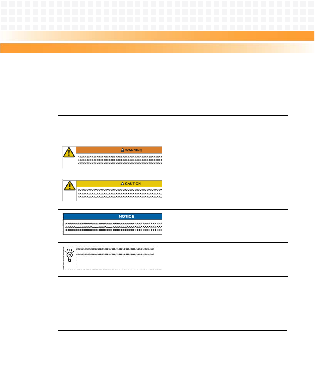
Indicates a hazardous situation which, if not avoided,
could result in death or serious injury
Indicates a hazardous situation which, if not avoided,
may result in minor or moderate injury
Summary of Changes
This manual has been revised and replaces all prior editions.
Part Number Publication Date Description
6806800G42A June 2008 First edition
6806800G42B December 2008 Updated to Emerson layout, editorial changes
14
Indicates a property damage message
No danger encountered. Pay attention to important
information
ATCA-7150 and RTM-ATCA-7150 Getting Started (6806800G42B)
Page 15

About this Manual
Comments and Suggestions
We welcome and appreciate your comments on our documentation. We want to know what
you think about our manuals and how we can make them better.
Mail comments to us by filling out the following online form:
http://www.emersonnetworkpowerembeddedcomputing.com/ > Contact Us > Online Form
In "Ar ea of I ntere st" selec t "Tec hni cal Doc ument ati on" . Be sur e to inc lud e th e ti tle, p ar t nu mber,
and revision of the manual and tell us how you used it.
ATCA-7150 and RTM-ATCA-7150 Getting Started (6806800G42B)
15
Page 16

About this Manual
About this Manual
16
ATCA-7150 and RTM-ATCA-7150 Getting Started (6806800G42B)
Page 17

Safety Notes
This section provides warnings that precede potentially dangerous procedures throughout
this manual. Instructions contained in the warnings must be followed during all phases of
operation, service, and repair of this equipment. You should also employ all other safety
precautions necessary for the operation of the equipment in your operating environment.
Failure to comply with these precautions or with specific warnings elsewhere in this manual
could result in personal injury or damage to the equipment.
Emerson Network Power intends to provide all necessary information to install and handle the
product in this manual. Because of the complexity of this product and its various uses, we do
not guarantee that the given information is complete. If you need additional information, ask
your Emerson Network Power representative.
The product has been designed to meet the standard industrial safety requirements. It must
not be used except in its specific area of office telecommunication industry and industrial
control.
Only personnel trained by Emerson Network Power or persons qualified in electronics or
electrical engineering are authorized to install, remove or maintain the product.
The information given in this manual is meant to complete the knowledge of a specialist and
must not be used as replacement for qualified personnel.
Keep away from live circuits inside the equipment. Operating personnel must not remove
equipment covers. Only Factory Authorized Service Personnel or other qualified service
personnel may remove equipment covers for internal subassembly or component replacement
or any internal adjustment.
Do not install substitute parts or perform any unauthorized modification of the equipment or
the warranty may be voided. Contact your local Emerson Network Power representative for
service and repair to make sure that all safety features are maintained.
EMC
This equipment has been tested and found to comply with the limits for a Class A digital device,
pursuant to Part 15 of the FCC Rules. These limits are designed to provide reasonable
protection against harmful interference when the equipment is operated in a commercial
environment. This equipment generates, uses, and can radiate radio frequency energy and, if
not installed and used in accordance with the instruction manual, may cause harmful
interference to radio communications.
ATCA-7150 and RTM-ATCA-7150 Getting Started (6806800G42B)
17
Page 18

Safety Notes
Operation of this equipment in a residential area is likely to cause harmful interference in which
case the user will be required to correct the interference at his own expense. Changes or
modifications not expressly approved by Emerson Network Power Embedded Computing
could void the user's authority to operate the equipment. Board products are tested in a
representative system to show compliance with the above mentioned requirements. A proper
installation in a compliant system will maintain the required performance. Use only shielded
cables when connecting peripherals to assure that appropriate radio frequency emissions
compliance is maintained.
Operation
Damage of the Product
Surface of the Product
High humidity and condensation on the product surface causes short circuits.
Do not operate the product outside the specified environmental limits. Make sure the product
is completely dry and there is no moisture on any surface before applying power.
Do not operate the product below -5°C.
Overheating and Damage of the Product
Operating the product without forced air cooling may lead to overheating and thus damage of
the product.
When operating the product, make sure that forced air cooling is available in the shelf.
Configuration Jumpers
Malfunction of the Product
Reserved jumpers might carry production-related functions and can cause the product to
malfunction if their setting is changed.
Therefore, do not change settings of jumpers marked as "Reserved".
18
ATCA-7150 and RTM-ATCA-7150 Getting Started (6806800G42B)
Page 19

Installation
Damage of the Product and Additional Devices and Modules
Incorrect installation or removal of additional devices or modules may damage the product or
the additional devices or modules.
Before installing or removing additional devices or modules, read the respective
documentation.
Damage of Circuits
Electrostatic discharge and incorrect installation and removal of the product can damage
circuits or shorten their life.
Before touching the product or electronic components, make sure that your are working in an
ESD-safe environment.
Safety Notes
Damage of the Product
Incorrect installation of the product can cause damage of the product.
Only use handles when installing/removing the product to avoid damage/deformation to the
face plate and/or PCB.
Damage to the Product/Backplane or System Components
Bent pins or loose components can cause damage to the product, the backplane, or other
system components.
Therefore, carefully inspect the product and the backplane for both pin and component
integrity before installation.
ATCA-7150 and RTM-ATCA-7150 Getting Started (6806800G42B)
19
Page 20

Safety Notes
Emerson Network Power Embedded Computing (ENPEC) and our suppliers take significant
steps to ensure there are no bent pins on the backplane or connector damage to the boards
prior to leaving the factory. Bent pins caused by improper installation or by inserting boards
with damaged connectors could void the ECC warranty for the backplane or boards.
Incorrect installation of the product can cause blade damage.
Only use handles for when installing/removing the product to avoid damage/deformation to
the face plate and/or PCB
Cabling and Connectors
Damage of the Product
The RJ-45 connector(s) on the face plate are either twisted-pair Ethernet (TPE) or E1/T1/J1
interfaces. Connecting an E1/T1/J1 line to an Ethernet connector may damage the product.
z Make sure that TPE connectors near your working area are clearly marked as network
connectors.
z Verify that the length of an electric cable connected to a TPE bushing does not exceed 100
meters.
z Make sure the TPE bushing of the product is connected only to safety extra low voltage
circuits (SELV circuits).
If in doubt, ask your system administrator.
Laser
This product is a Class 1 laser product. The use of controls or adjustments or performance of
procedures other than those specified herein may result in hazardous radiation exposure.
Environment
Always dispose of used blades, system components and RTMs according to your country’s
legislation and manufacturer’s instructions.
20
ATCA-7150 and RTM-ATCA-7150 Getting Started (6806800G42B)
Page 21

Battery
Board/System damage
Incorrect exchange of lithium batteries can result in a hazardous explosion.
When exchanging the on-board lithium battery, make sure that the new and the old battery
are exactly the same battery models.
If the respective battery model is not available, contact your local Emerson Network Power
sales representative for the availablity of alternative officially approved battery models.
Safety Notes
ATCA-7150 and RTM-ATCA-7150 Getting Started (6806800G42B)
21
Page 22

Safety Notes
22
ATCA-7150 and RTM-ATCA-7150 Getting Started (6806800G42B)
Page 23

Sicherheitshinweise
Dieses Kapitel enthält Hinweise, die potentiell gefährlichen Prozeduren innerhalb dieses
Handbuchs vorrangestellt sind. Beachten Sie unbedingt in allen Phasen des Betriebs, der
Wartung und der Reparatur des Systems die Anweisungen, die diesen Hinweisen enthalten
sind. Sie sollten außerdem alle anderen Vorsichtsmaßnahmen treffen, die für den Betrieb des
Produktes innerhalb Ihrer Betriebsumgebung notwendig sind. Wenn Sie diese
Vorsichtsmaßnahmen oder Sicherheitshinweise, die an anderer Stelle diese Handbuchs
enthalten sind, nicht beachten, kann das Verletzungen oder Schäden am Produkt zur Folge
haben.
Emerson ist darauf bedacht, alle notwendigen Informationen zum Einbau und zum Umgang
mit dem Produkt in diesem Handbuch bereit zu stellen. Da es sich jedoch um ein komplexes
Produkt mit vielfältigen Einsatzmöglichkeiten handelt, können wir die Vollständigkeit der im
Handbuch enthaltenen Informationen nicht garantieren. Falls Sie weitere Informationen
benötigen sollten, wenden Sie sich bitte an die für Sie zuständige Geschäftsstelle von Emerson.
Das System erfüllt die für die Industrie geforderten Sicherheitsvorschriften und darf
ausschließlich für Anwendungen in der Telekommunikationsindustrie und im Zusammenhang
mit Industriesteuerungen verwendet werden.
Einbau, Wartung und Betrieb dürfen nur von durch Emerson ausgebildetem oder im Bereich
Elektronik oder Elektrotechnik qualifiziertem Personal durchgeführt werden. Die in diesem
Handbuch enthaltenen Informationen dienen ausschließlich dazu, das Wissen von
Fachpersonal zu ergänzen, können dieses jedoch nicht ersetzen.
Halten Sie sich von stromführenden Leitungen innerhalb des Produktes fern. Entfernen Sie auf
keinen Fall Abdeckungen am Produkt. Nur werksseitig zugelassenes Wartungspersonal oder
anderweitig qualifiziertes Wartungspersonal darf Abdeckungen entfernen, um Komponenten
zu ersetzen oder andere Anpassungen vorzunehmen.
Installieren Sie keine Ersatzteile oder führen Sie keine unerlaubten Veränderungen am Produkt
durch, sonst verfällt die Garantie. Wenden Sie sich für Wartung oder Reparatur bitte an die für
Sie zuständige Geschäftsstelle von Emerson. So stellen Sie sicher, dass alle
sicherheitsrelevanten Aspekte beachtet werden.
ATCA-7150 and RTM-ATCA-7150 Getting Started (6806800G42B)
23
Page 24

Sicherheitshinweise
EMV
Das Produkt wurde in einem Emerson Network Power Standardsystem getestet. Es erfüllt die
für digitale Geräte der Klasse A gültigen Grenzwerte in einem solchen System gemäß den FCCRichtlinien Abschnitt 15 bzw. EN 55022 Klasse A. Diese Grenzwerte sollen einen
angemessenen Schutz vor Störstrahlung beim Betrieb des Produktes in Gewerbe- sowie
Industriegebieten gewährleisten.
Das Produkt arbeitet im Hochfrequenzbereich und erzeugt Störstrahlung. Bei
unsachgemäßem Einbau und anderem als in diesem Handbuch beschriebenen Betrieb können
Störungen im Hochfrequenzbereich auftreten.
Wird das Produkt in einem Wohngebiet betrieben, so kann dies mit grosser Wahrscheinlichkeit
zu starken Störungen führen, welche dann auf Kosten des Produktanwenders beseitigt werden
müssen. Änderungen oder Modifikationen am Produkt, welche ohne ausdrückliche
Genehmigung von Emerson Network Power EC durchgeführt werden, können dazu führen,
dass der Anwender die Genehmigung zum Betrieb des Produktes verliert. Boardprodukte
werden in einem repräsentativen System getestet, um zu zeigen, dass das Board den oben
aufgeführten EMV-Richtlinien entspricht. Eine ordnungsgemässe Installation in einem System,
welches die EMV-Richtlinien erfüllt, stellt sicher, dass das Produkt gemäss den EMV-Richtlinien
betrieben wird. Verwenden Sie nur abgeschirmte Kabel zum Anschluss von Zusatzmodulen. So
ist sichergestellt, dass sich die Aussendung von Hochfrequenzstrahlung im Rahmen der
erlaubten Grenzwerte bewegt.
Warnung! Dies ist eine Einrichtung der Klasse A. Diese Einrichtung kann im Wohnbereich
Funkstörungen verursachen. In diesem Fall kann vom Betreiber verlangt werden,
angemessene Maßnahmen durchzuführen.
Betrieb
Beschädigung des Produktes
Hohe Luftfeuchtigkeit und Kondensat auf der Oberfläche des Produktes können zu
Kurzschlüssen führen.
Betreiben Sie das Produkt nur innerhalb der angegebenen Grenzwerte für die relative
Luftfeuchtigkeit und Temperatur. Stellen Sie vor dem Einschalten des Stroms sicher, dass sich
auf dem Produkt kein Kondensat befindet und betreiben Sie das Produkt nicht unter -5°C.
24
ATCA-7150 and RTM-ATCA-7150 Getting Started (6806800G42B)
Page 25

Überhitzung und Beschädigung des Produktes
Betreiben Sie das Produkt ohne Zwangsbelüftung, kann das Produkt überhitzt und schließlich
beschädigt werden.
Bevor Sie das Produkt betreiben, müssen Sie sicher stellen, dass das Shelf über eine
Zwangskühlung verfügt.
Jumper
Fehlfunktion des Produktes
Schalter, die mit 'Reserved' sind, können mit produktionsrelevanten Funktionen belegt sein.
Das Ändern dieser Schalter kann im normalen Betrieb Störungen auslösen.
Installation
Sicherheitshinweise
Beschädigung des Produktes und von Zusatzmodulen
Fehlerhafte Installation von Zusatzmodulen, kann zur Beschädigung des Produktes und der
Zusatzmodule führen.
Lesen Sie daher vor der Installation von Zusatzmodulen die zugehörige Dokumentation.
Beschädigung von Schaltkreisen
Elektrostatische Entladung und unsachgemäßer Ein- und Ausbau des Produktes kann
Schaltkreise beschädigen oder ihre Lebensdauer verkürzen.
Bevor Sie das Produkt oder elektronische Komponenten berühren, vergewissern Sie sich, daß
Sie in einem ESD-geschützten Bereich arbeiten.
Beschädigung des Produktes
Fehlerhafte Installation des Produktes kann zu einer Beschädigung des Produktes führen.
Verwenden Sie die Handles, um das Produkt zu installieren/deinstallieren. Auf diese Weise
vermeiden Sie, dass das Face Plate oder die Platine deformiert oder zerstört wird.
ATCA-7150 and RTM-ATCA-7150 Getting Started (6806800G42B)
25
Page 26

Sicherheitshinweise
Beschädigung des Produktes, der Backplane oder von System Komponenten
Verbogene Pins oder lose Komponenten können zu einer Beschädigung des Produktes, der
Backplane oder von Systemkomponenten führen.
Überprüfen Sie daher das Produkt sowie die Backplane vor der Installation sorgältig und stellen
Sie sicher, dass sich beide in einwandfreien Zustand befinden und keine Pins verbogen sind.
Emerson Network Power Embedded Computing (ENPEC) und unsere Zulieferer unternehmen
größte Anstrengungen um sicherzustellen, dass sich Pins und Stecker von Boards vor dem
Verlassung der Produktionsstätte in einwandfreiem Zustand befinden. Verbogene Pins,
verursacht durch fehlerhafte Installation oder durch Installation von Boards mit beschädigten
Steckern kann die durch ECC gewährte Garantie für Boards und Backplanes erlöschen lassen.
Kabel und Stecker
Beschädigung des Produktes
Bei den RJ-45-Steckern, die sich an dem Produkt befinden, handelt es sich entweder um
Twisted-Pair-Ethernet (TPE) oder um E1/T1/J1-Stecker. Beachten Sie, dass ein versehentliches
Anschließen einer E1/T1/J1-Leitung an einen TPE-Stecker das Produkt zerstören kann.
z Kennzeichnen Sie deshalb TPE-Anschlüsse in der Nähe Ihres Arbeitsplatzes deutlich als
Netzwerkanschlüsse.
z Stellen Sie sicher, dass die Länge eines mit Ihrem Produkt verbundenen TPE-Kabels 100 m
nicht überschreitet.
z Das Produkt darf über die TPE-Stecker nur mit einem Sicherheits-Kleinspannungs-
Stromkreis (SELV) verbunden werden.
Bei Fragen wenden Sie sich an Ihren Systemverwalter.
Laser
Einige Varianten des Produktes sind Laserprodukte der Klasse 1. Um nicht schädlicher
Laserstrahlung ausgesetzt zu werden, beachten Sie die folgenden Hinweise: Anpassungen am
Produkt, die Bedienung von Steuerelementen sowie die Durchführung von Prozeduren dür fen
nur gemäß den Anweisungen in diesem Dokument erfolgen.
26
ATCA-7150 and RTM-ATCA-7150 Getting Started (6806800G42B)
Page 27

Umweltschutz
Entsorgen Sie alte Batterien und Blades/RTMs stets gemäß der in Ihrem Land gültigen
Gesetzgebung und den Empfehlungen des Herstellers.
Batterie
Beschädigung des Produktes
Ein unsachgemäßer Einbau der Batterie kann gefährliche Explosionen und Beschädigungen
des Produktes zur Folge haben.
Verwenden Sie deshalb nur den Batterietyp, der auch bereits eingesetzt wurde und befolgen
Sie die Installationsanleitung.
Falls der entsprechende Batterietyp nicht verfügbar ist, kontaktieren Sie Ihren lokalen Emerson
Network Power-Ansprechpartner und erfragen Sie die Verfügbarkeit von alternativen, offiziell
zugelassenen Batteriemodellen.
Sicherheitshinweise
ATCA-7150 and RTM-ATCA-7150 Getting Started (6806800G42B)
27
Page 28

Sicherheitshinweise
28
ATCA-7150 and RTM-ATCA-7150 Getting Started (6806800G42B)
Page 29

Chapter: 1
Introduction
1.1 Features
The ATCA-7150 and RTM-ATCA-7150 server blade suite features the capabilities of high speed
calculation and mass data processing.
The ATCA-7150 and RTM-ATCA-7150 suite consists of:
z ATCA-7150 and RTM-ATCA-7150
z RTM-ATCA-7150
The RTM-ATCA-7150 is the rear transition module (RTM) of the server blade.
A server blade must work with an RTM of the server blade. For example, the ATCA-7150 works
with the RTM-ATCA-7150.
You can install the ATCA-7150 in any node slot of your shelf. The RTM-ATCA-7150 is installed
in the slot that is paired with the ATCA-7150 slot.
ATCA-7150 and RTM-ATCA-7150 Getting Started (6806800G42B)
29
Page 30
Introduction
Figure 1-1 shows the connection between the ATCA-7150 and the RTM of the server blade.
RTM of the
server blade
Backplane
ATCA-
7150
Figure 1-1 Connection Between the ATCA-7150 and the RTM
You can choose to use the RTM-ATCA-7150 according to the actual application.
The backplane is one part of the shelf. For details on the backplane and shelf, refer to the
respective system documentation.
30
ATCA-7150 and RTM-ATCA-7150 Getting Started (6806800G42B)
Page 31

Introduction
Table 1-1 lists the functions of the ATCA-7150 and the RTM.
Table 1-1 Functions of the ATCA-7150 and the RTM
Function Description
Processing functions z Supports two dual-core LV Intel Xeon 5138 (2.13 GHz)
processors
z Supports 4 MB L2 cache
z Supports up to four FB-DIMMs
z Supports the DIMM with a capacity of 512 MB, 1 GB, 2 GB, or 4
GB. The maximum capacity is 16 GB
Interface functions z 10/100/1000Base-T
z 1000Base-BX
z 1000Base-BX
z Provides two USB 2.0 interfaces (compatible with USB 1.1)
z Provides one IPMC serial port (also used as the system serial
port, the serial port standards are RS232 and RJ-45)
z Provides serial port to access CPU and IPMC serial console
z Provides two SAS hard disks
z The RTM-ATCA-7150 that works with the ATCA-7150 provides a
monitor interface and a USB 2.0 interface (compatible with
USB1.1). Through optional daughter cards, the RTM-ATCA-7150
can also provide external GE interfaces, and FC interfaces.
Management functions The ATCA-7150 provides the IPMC that is powered independently.
The IPMC is connected to the ShMC through the redundant IPMB.
The IPMC provides the following functions:
z Environmental sensors temperature, voltage
z System Event Logs
z Watchdog timer
z Power-on, power-off, cold reset
z SOL(Serial Over LAN)
z FRU Hot-swap management
z E-Keying control
Integrity functions z Dual-channel GE controller
z IPMI
z SAS storage controller
z Video controller
ATCA-7150 and RTM-ATCA-7150 Getting Started (6806800G42B)
31
Page 32

Introduction
1.2 Standard Compliances
This product meets the following standards.
Table 1-2 Standard Compliances
Standard Description
UL 60950-1
EN 60950-1
IEC 60950-1
CAN/CSA C22.2 No 60950-1
CISPR 22
CISPR 24
EN 55022
EN 55024
FCC Part 15
Industry Canada ICES-003
VCCI Japan
AS/NZS CISPR 22
EN 300 386
NEBS Standard GR-1089 CORE
Legal safety requirements
EMC re quirements ( legal) on s ystem level ( predefined Emerson
Network Power system)
NEBS Standard GR-63-CORE
ETSI EN 300019 series
PICMG 3.0 Defines mechanics, blade dimensions, power distribution,
Environmental requirements
power and data connectors, and system management
1.3 Ordering Information
When ordering board variants or board accessories, use the order numbers given on the
following pages.
32
ATCA-7150 and RTM-ATCA-7150 Getting Started (6806800G42B)
Page 33

Introduction
1.3.1 Supported Board Models
The following table explains the product nomenclature used for the available board variants.
Table 1-3 Product Nomenclature
Order Number Description
ATCA-7150-0GB ATCA Processor Blade with Dual Core Intel® Xeon® Processor
LV5138.
Can be equipped with up to 16GB DDR2 memory.
1G fabric interface.
ATCA-7X50-MEM-2G 2G Memory Module (min 1, max 4 modules of the same type per
blade)
ATCA-7X50-MEM-4G 4G Memory Module (min 1, max 4 modules of the same type per
blade)
RTM-ATCA-7150-GE Rear Transition Module for ATCA-7150, 2x 1G Ethernet
RTM-ATCA-7150-GE-FC Rear Transition Module for ATCA-7150, 2x 1G Eth, 2x FC
ATCA7X50-HDD1-SAS Enterprise Class HDD, SAS, 72GB
ATCA7X50-HDD2-SAS Enterprise Class HDD, SAS, 146GB
ATCA7X50-HDD3-SATA Automotive HDD, SATA, 80GB
ATCA-7150-8GB-1HDD1 ATCA Processor Blade with Dual Core Intel® Xeon® Processor
LV5138, 8GB (4x 2GB) Memory, 1x Enterprise Class HDD, SAS,
72GB
ATCA7X50-SSD2-SATA Solid State Disk, SATA, 32GB
1.3.2 Board Accessories
As of the printing date of this manual, the following board accessories were available.
Table 1-4 Available Board Accessories
Board Accesories Order Number
Gigabit Ethernet (GE) daughter card MEZC-RTM-7150-GE
Fiber Channel (FC) daughter card MEZC-RTM-7150-FC
ATCA-7150 and RTM-ATCA-7150 Getting Started (6806800G42B)
33
Page 34

Introduction
Table 1-4 Available Board Accessories (continued)
Board Accesories Order Number
ATCA7X50-HDDx-SAS/SATA ATCA7X50-HDD1-SAS
ATCA7X50-HDD2-SAS
ATCA7X50-HDD3-SATA
ATC A7 X5 0
34
ATCA-7150 and RTM-ATCA-7150 Getting Started (6806800G42B)
Page 35

Chapter: 2
Installation of the RTM-ATCA-7150
2.1 Overview
This chapter describes:
z Unpacking and inspecting RTM-ATCA-7150
z Precautions during the operation
z Preparations before installation
z Installation procedure
z Installing and replacing daughter cards
z Connection of external cables
z Removal procedure
2.2 Unpacking and Inspecting RTM-ATCA-7150
Damage of Circuits
Electrostatic discharge and incorrect installation and removal of the product can damage
circuits or shorten their life.
Before touching the product or electronic components, make sure that your are working in
an ESD-safe environment.
Shipment Inspection
To inspect the shipment, perform the following steps.
1. Verify that you have received all items of your shipment:
Printed "Getting Started" guide
RTM-ATCA-7150
Any optional items ordered
2. Check for damage and report any damage or differences to the customer service.
ATCA-7150 and RTM-ATCA-7150 Getting Started (6806800G42B)
35
Page 36

Installation of the RTM-ATCA-7150
3. Remove the desiccant bag shipped together with the blade and dispose of it
according to your country’s legislation.
The product is thoroughly inspected before shipment. If any damage occurred during
transportation or any items are missing, please contact our customer's service immediately.
2.3 Environmental and Power Requirements
The following environmental and power requirements are applicable to the board.
2.3.1 Environmental Requirements
Table 2-1 Environmental Requirements RTM-ATCA-7150
Requirement Operating Non-Operating
Temperature +5ºC (41ºF) to +40ºC (104ºF) (normal operation)
according to NEBS Standard GR-63-CORE
-5ºC to +55ºC (short term operation) according
to NEBS Standard GR-63-CORE
Temp. Change +/- 0.25ºC/min or 15ºC/h (59ºF/h) according to
NEBS Standard GR-63-CORE
Rel. Humidity 5% to 85% non-condensing according to
Emerson Network Power Embedded
Computing-internal environmental
requirements
Altitude <= 4000m
-40ºC (-40ºF) to +70ºC
(158ºF) (may be further
limited by installed
accessories)
+/- 0.25ºC/min or 15ºC/h
(59ºF/h)
5% to 85% non-condensing
according to Emerson
Network Power Embedded
Computing-internal
environmental
requirements
36
ATCA-7150 and RTM-ATCA-7150 Getting Started (6806800G42B)
Page 37

Installation of the RTM-ATCA-7150
Table 2-1 Environmental Requirements RTM-ATCA-7150 (continued)
Requirement Operating Non-Operating
Vibration 1.0g from 5 to 100 Hz and back to 5 Hz at a rate
of 0.1 octave/minute
Shock Half-sine, 11 m/Sec, 30mSec/sec
Free Fall 1,200 mm/all edges and
2.3.2 Power Requirements
Table 2-2 Power Requirements RTM-ATCA-7150
5-20 Hz @ 0.01 g2/Hz
20-200 Hz @ -3.0 dB/octave
Random 5-20 Hz @ 1
2
3
m
/Sec
Random 20-200 Hz @ -3
2
m/Sec
2
Blade level packaging
Half-sine, 6 mSec at 180
2
m/Sec
corners
1.0m (Packaged) per ETSI
300 019-2-2 (Blade level
packaging)
100mm (unpackaged) per
GR-63-CORE
Requirement Operating
Power supply Provided by the server blade
Maximum power consumption 14.2 W
ATCA-7150 and RTM-ATCA-7150 Getting Started (6806800G42B)
37
Page 38

Installation of the RTM-ATCA-7150
2.4 Module Installation and Removal
Personal Damage through Electric Shock
There is current in the power cords and communication cables. Touching the connectors of
the power cords and communication cables may cause electric shock.
Do not touch the connectors of power cords and communication cables
Damage of Circuits
Electrostatic discharge and incorrect installation and removal of the product can damage
circuits or shorten their life.
Before touching the product or electronic components, make sure that your are working in
an ESD-safe environment.
Module Damage
If the blade is not fully aligned with the interface in the backplane, too much force may twist
the pins on the blade or backplane.
Do not exert too much force when you insert the blade.
Note the following points at the time of installing RTM-ATCA-7150:
z Make sure that you wear an electrostatic discharge (ESD)-preventive wrist strap to prevent
the static electricity from hurting you or damaging the device.
z Keep your personal objects such as your clothes away from RTM-ATCA-7150. To prevent
the static electricity on clothing, you need to put on antistatic clothing.
z RTM-ATCA-7150 is installed in the slot paired with the server blade slot at the back side of
the shelf. You should install RTM-ATCA-7150 before the server blade is installed.
Otherwise, RTM-ATCA-7150 cannot be powered on normally.
38
ATCA-7150 and RTM-ATCA-7150 Getting Started (6806800G42B)
Page 39

Installation of the RTM-ATCA-7150
z Hold the ejector handles and the face plate when you insert or remove RTM-ATCA-7150.
Do not touch the components inside of the blades.
z Keep the blade vertical when you install RTM-ATCA-7150. Align the blade with the slot and
then insert it in the shelf.
2.4.1 Ejector Handles
RTM-ATCA-7150 is powered by the server blade in the slot paired with the RTM-ATCA-7150
slot. RTM-ATCA-7150 does not support hot swap. The face plate of ATCA-7150 and RTM-ATCA7150 provides an upper and a lower ejector handles. The ejector handles help to insert,
remove, fasten, power on, and power off RTM-ATCA-7150.
2.4.2 ESD Prevention
Static electricity may hurt you or damage the device. To minimize the damage, pay attention
to the following points:
z Before you operate the device, wear the ESD-preventive wrist strap. Both terminals of the
ESD-preventive wrist strap must contact well. One terminal touches your bare skin, and
the other is inserted in the jack at the front or back side of the shelf. For details on how to
wear the ESD-preventive wrist strap, refer Wearing the ESD-Preventive Wrist Strap.
z Avoid moving your body as much as possible. Movement gathers static electricity around
you.
z Do not touch the solder point, pin, or bare circuit.
z Do not leave the device in the place where others can operate it.
z Install the device at once after you take it out of the antistatic package. If you need to lay
down the device, place it back in the antistatic package. Do not lay the device on the shelf
or cabinet.
z Monitor the temperature and humidity of the equipment room. Warm air decreases the
humidity and increases the static electricity in the room.
ATCA-7150 and RTM-ATCA-7150 Getting Started (6806800G42B)
39
Page 40

Installation of the RTM-ATCA-7150
2.5 Installation Preparations
The installation preparations process includes:
z check the installation environment
z wear the ESD-preventive wrist strap
z remove the blank filler panels
z unpack and check the RTM-ATCA-7150 suite
2.5.1 Wearing the ESD-Preventive Wrist Strap
Module Damage
z Electrostatic discharge can damage circuits or shorten their life.
z The ESD-preventive wrist strap prevents only the static electricity on your body from
da magin g the bla de. To p revent t he s tat ic elec tr ici ty on you r cl oth es, it is r eco mme nde d
to wear the antistatic clothes. Additionally, you have to make sure that the cabinet and
shelf are properly grounded - for details, refer to the corresponding system
documentation.
40
ATCA-7150 and RTM-ATCA-7150 Getting Started (6806800G42B)
Page 41

Installation of the RTM-ATCA-7150
To wear the ESD-preventive wrist strap, proceed as follows:
1. Wrap the ESD-preventive wrist strap around your wrist, as shown in the figure
below.
2. Fasten the latch. Make sure that the ESD-preventive wrist strap well touches your
bare wrist.
3. Insert the grounding terminal of the ESD-preventive wrist strap in the jack of the
cabinet or shelf.
There is a jack for inserting the ESD-preventive wrist strap respectively in the lower right
corners at both front and back sides of the shelf.
Figure 2-1 Wearing the ESD-Preventive Wrist Strap
ATCA-7150 and RTM-ATCA-7150 Getting Started (6806800G42B)
41
Page 42

Installation of the RTM-ATCA-7150
2.5.2 Removing Filler Blades
After a filler blade is removed, place it in the equipment room or other moisture-proof and
dust-proof places.
You should install a blank filler blade in the slot after removing the blade. Otherwise, it may
effect the ventilation, heat dissipation, electromagnetic shielding and dust prevention of the
shelf.
If this is the first installation for the shelf, the blade is fully configured and the shelf is not
powered on, you can remove all the filler blades. Then, install blades in the slots in order. This
document takes the first installation as an example.
If you want to install multiple blades in the shelf that is powered on shelf, you can remove a
filler blade and then install a blade one by one.
If the slot is occupied with a filler blade you have to remove it first.
42
ATCA-7150 and RTM-ATCA-7150 Getting Started (6806800G42B)
Page 43

Installation of the RTM-ATCA-7150
To remove the filler blade, proceed as follows:
1
1
2
1. As shown in step 1 of the figure below, use a screwdriver to anticlockwise loosen
the two captive screws on a filler blade.
2. As shown in step 2 of the figure below, remove the filler blade.
Figure 2-2 Removing the Filler Blade
2.6 Installing and Replacing Daughter Cards
ATCA-7150 and RTM-ATCA-7150 Getting Started (6806800G42B)
43
Page 44
Installation of the RTM-ATCA-7150
2.6.1 Precautions
Incorrect installation or removal of additional devices or modules may damage the product
or the additional devices or modules.
Before installing or removing additional devices or modules, read the respective
documentation.
Electrostatic discharge and incorrect installation and removal of the product can damage
circuits or shorten their life.
Before touching the product or electronic components, make sure that your are working in
an ESD-safe environment.
Do not exert too much force when you insert the blade.
If the blade is not fully aligned with the interface in the backplane, too much force may twist
the pins on the blade or backplane.
Do not touch the connectors of power cords and communication cables.
There is current in the power cords and communication cables. Touch on the connectors of
the power cords and communication cables may cause electric shock.
Note the following points at the time of installing or replacing components:
z Make sure that you wear an electrostatic discharge (ESD)-preventive wrist strap to prevent
the static electricity from hurting you or damaging the device.
z Keep the area where the components reside clean and keep the components away from
the heat-generating devices, such as radiators.
44
ATCA-7150 and RTM-ATCA-7150 Getting Started (6806800G42B)
Page 45

Installation of the RTM-ATCA-7150
z Ensure that your sleeves are tightened or rolled up above the elbow. For safety purpose, it
is not recommended to wear jewelry, watch, glasses with metal frame, or clothes with
metal buttons.
z Do not exert too much force, or insert or remove the components forcibly. Avoid damage
to the components or plug-ins, for example, the pins are bent or get short circuit.
2.6.2 Preparations
Before you install or replace a component, make the following preparations
z Confirming the feasibility of the operation
— There are available spare parts of the component to be installed or replaced in the
equipment warehouse. When the available spare parts are in short supply, contact
Emerson Network Power Embedded Computing for help in time.
— Make sure that the new component is in good condition, without defects such as
oxidation, chemical corrosion, missing component, or transportation damage.
— By reading this document, you are familiar with how to install and replace the
component and master the skills required by the operation.
z Checking the environment
Make sure that the shelf, power supply, temperature, and humidity meet the operating
requirements of the blades and components. For details, refer to ATCA-7150 Installation
and Use Manual and other related documents.
z Preparing spare parts and tools
— Prepare the component to be installed or replaced.
When you hold or transport the component, use the special antistatic package. In
addition, you need to tidy, record, and repair the component during routine
maintenance.
— Prepare the cross screwdriver, screws, plastic supports, cooling gel, and ESD-
preventive wrist strap.
The supplier provides a list of tools and negotiates with you to decide the tool provider.
z Confirming installation or changing positions
Confirm the positions of the cabinet, the shelf, and the slot where RTM-ATCA-7150 is
installed. Then, stick a label on the face plate of RTM-ATCA-7150 to avoid wrong operation.
ATCA-7150 and RTM-ATCA-7150 Getting Started (6806800G42B)
45
Page 46

Installation of the RTM-ATCA-7150
z Others
If a serious problem occurs and cannot be solved when you install or replace the
component, contact Emerson Network Power Embedded Computing for technical
support.
2.6.3 GE Daughter Card
This manual considers the GE daughter card providing two external Ethernet interfaces as an
example, and describes how to install the daughter card on and remove it from RTM-ATCA-
7150.
46
ATCA-7150 and RTM-ATCA-7150 Getting Started (6806800G42B)
Page 47

Installation of the RTM-ATCA-7150
2.6.3.1 Installation Positions
When the GE daughter card is used with the RTM-ATCA-7150 it can be installed on the
daughter card connector J1, J2, J3, J4. The default position as used on the RTM-ATCA-7150-GE
is position J4. The default position as used on the RTM-ATCA-7150-GE-FC is position J1.
Figure 2-3 Structure of RTM-ATCA-7150
ATCA-7150 and RTM-ATCA-7150 Getting Started (6806800G42B)
47
Page 48

Installation of the RTM-ATCA-7150
2.6.3.2 Installing the GE Daughter Card
To install the GE daughter card, proceed as follows.
1. Wear the ESD-preventive wrist strap. For more information refer, Wearing the ESD-
Preventive Wrist Strap.
2. Lay RTM-ATCA-7150 where the GE daughter card is to be installed on the antistatic
desktop.
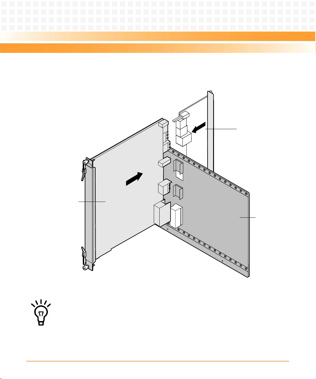
3. As shown in step 1 of the figure below, insert two plastic supports vertically in the
holes used to fasten the GE daughter card.
4. As shown in step 2 of the figure below, at the back side of RTM-ATCA-7150, use a
screwdriver to clockwise fasten the two screws used to fix the plastic supports.
5. Take the GE daughter card out of the antistatic package.
48
ATCA-7150 and RTM-ATCA-7150 Getting Started (6806800G42B)
Page 49

Installation of the RTM-ATCA-7150
6. Insert the GE daughter card in RTM-ATCA-7150 by facing the daughter card at an
angle of 45° to the RTM. Align the daughter card connector with the connector on
RTM-ATCA-7150, and the daughter card positioning holes with the plastic supports
on RTM-ATCA-7150. Exert even power downwards until the daughter card
connector is fully inserted into the connector on RTM-ATCA-7150 and the daughter
ATCA-7150 and RTM-ATCA-7150 Getting Started (6806800G42B)
49
Page 50

Installation of the RTM-ATCA-7150
card is fastened by the plastic latches. See step 3 in the figure below.
1
2
3
Figure 2-4 Installing the GE Daughter Card
50
ATCA-7150 and RTM-ATCA-7150 Getting Started (6806800G42B)
Page 51

Installation of the RTM-ATCA-7150
7. Insert RTM-ATCA-7150 with the GE daughter card installed in the shelf. For more
information refer, Installing RTM-ATCA-7150.
After installation, check if RTM-ATCA-7150 can be powered on and work normally. Use the
network cable to connect RTM-ATCA-7150 to the external network. Check if the network is
connected properly and monitor whether the network port indicator is normal.
2.6.3.3 Replacing the GE Daughter Card
To replace the GE daughter card, proceed as follows.
1. Wear the ESD-preventive wrist strap. For more information refer, Wearing the ESD-
Preventive Wrist Strap.
2. Remove the RTM-ATCA-7150 whose GE daughter card is to be replaced. For more
information refer, Removing RTM-ATCA-7150.
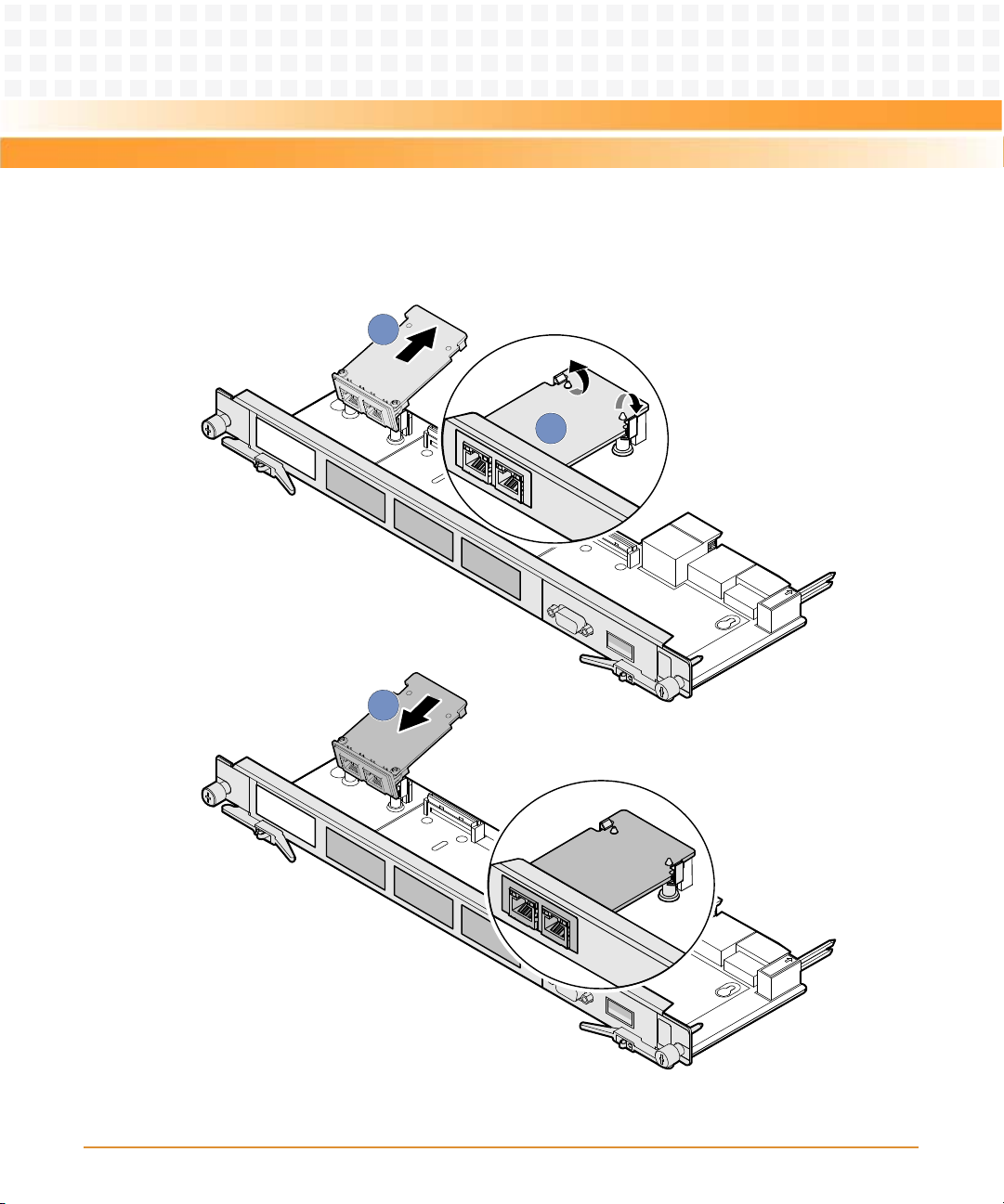
3. As shown in step 1 of the figure below, open the plastic latches fastening the GE
daughter card.
4. Exert even force upwards until the daughter card connector is removed from the
connector on RTM-ATCA-7150. As shown in step 2 of the figure below, remove the
daughter card by facing the daughter card at an angle of 45° to the RTM.
5. Place the removed GE daughter card in an antistatic package.
ATCA-7150 and RTM-ATCA-7150 Getting Started (6806800G42B)
51
Page 52
Installation of the RTM-ATCA-7150
6. Take the new GE daughter card out of the antistatic package.
2
3
1
Figure 2-5 Replacing the GE Daughter Card.
52
ATCA-7150 and RTM-ATCA-7150 Getting Started (6806800G42B)
Page 53

Installation of the RTM-ATCA-7150
7. Insert the GE daughter card in RTM-ATCA-7150 by facing the daughter card at an
angle of 45° to the RTM. Align the daughter card connector with the connector on
RTM-ATCA-7150, and the daughter card positioning holes with the plastic supports
on RTM-ATCA-7150. Exert even power downwards until the daughter card
connector is fully inserted into the connector on RTM-ATCA-7150 and the daughter
card is fastened by the plastic latches. See step 3 in the figure above.
8. Install RTM-ATCA-7150 whose GE daughter card is replaced. For more information
refer, Installing RTM-ATCA-7150.
After replacement, check if RTM-ATCA-7150 can be powered on and work normally. Use the
network cable to connect RTM-ATCA-7150 to the external network. Check if the network is
connected properly and monitor whether the network port indicator is normal.
2.6.4 FC Daughter Card
This manual considers the FC daughter card providing two external FC interfaces as an
example, and describes how to install the daughter card on and remove it from RTM-ATCA-
7150.
2.6.4.1 Installation Positions
When the FC daughter card is used with the RTM-ATCA-7150 it can be installed on the
daughter card connector J2, J4. The default position as used on the RTM-ATCA-7150-GE-FC is
position J4 and J1.
2.6.4.2 Installing the FC Daughter Card
To install the FC daughter card, proceed as follows.
1. Wear the ESD-preventive wrist strap. For more information refer, Wearing the ESD-
Preventive Wrist Strap.
2. Lay RTM-ATCA-7150 where the FC daughter card is to be installed on the antistatic
desktop.
ATCA-7150 and RTM-ATCA-7150 Getting Started (6806800G42B)
53
Page 54

Installation of the RTM-ATCA-7150
3. As shown in step 1 of the figure below, insert two plastic supports vertically in the
holes used to fasten the FC daughter card.
4. As shown in step 2 of the figure below, at the back side of RTM-ATCA-7150, use a
screwdriver to clockwise fasten the two screws used to fix the plastic supports.
5. Take the FC daughter card out of the antistatic package.
54
ATCA-7150 and RTM-ATCA-7150 Getting Started (6806800G42B)
Page 55

Installation of the RTM-ATCA-7150
6. Insert the GE daughter card in RTM-ATCA-7150 by facing the daughter card at an
angle of 45° to the RTM. Align the daughter card connector with the connector on
RTM-ATCA-7150, and the daughter card positioning holes with the plastic supports
on RTM-ATCA-7150. Exert even power downwards until the daughter card
connector is fully inserted into the connector on RTM-ATCA-7150 and the daughter
ATCA-7150 and RTM-ATCA-7150 Getting Started (6806800G42B)
55
Page 56

Installation of the RTM-ATCA-7150
card is fastened by the plastic latches. See step 3 in the figure below.
3
2
1
Figure 2-6 Installing the FC Daughter Card
7. Insert RTM-ATCA-7150 with the FC daughter card installed in the shelf. For more
56
ATCA-7150 and RTM-ATCA-7150 Getting Started (6806800G42B)
Page 57

Installation of the RTM-ATCA-7150
information refer, Installing RTM-ATCA-7150.
After installation, check if RTM-ATCA-7150 can be powered on and work normally. Use the
optical fiber to connect RTM-ATCA-7150 to the external storage system. Check if RTM-ATCA7150 can transmit data normally and monitor whether the FC status indicator is normal.
2.6.4.3 Replacing the FC Daughter Card
To replace the FC daughter card, proceed as follows.
1. Wear the ESD-preventive wrist strap. For more information refer, Wearing the ESD-
Preventive Wrist Strap.
2. Remove the RTM-ATCA-7150 whose FC daughter card is to be replaced. For more
information refer, Removing RTM-ATCA-7150.
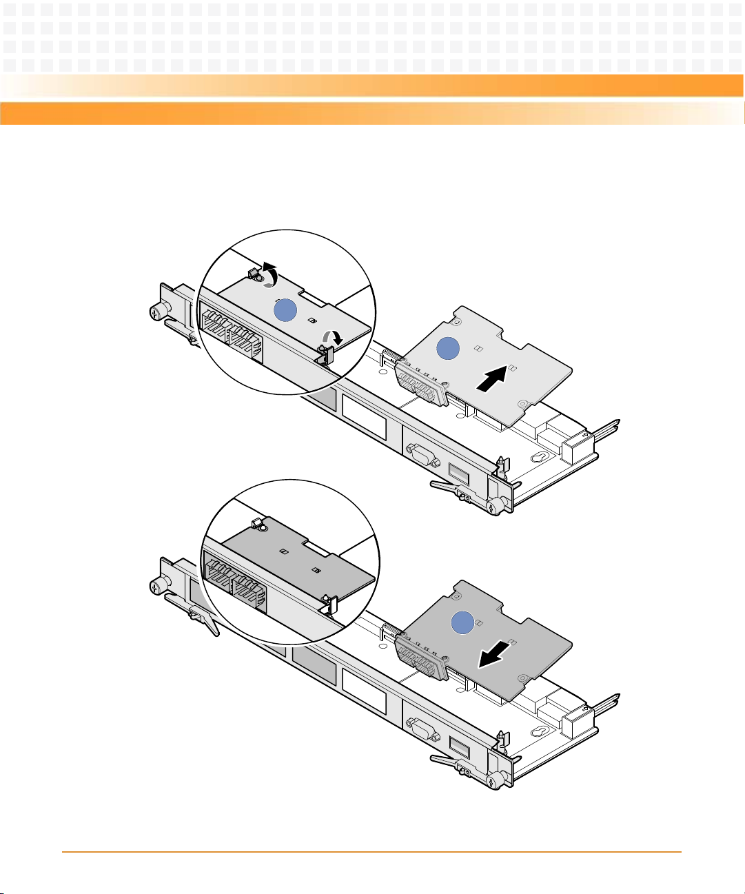
3. As shown in step 1 of the figure below, open the plastic latches fastening the FC
daughter card.
4. Exert even force upwards until the daughter card connector is removed from the
connector on RTM-ATCA-7150. As shown in step 2 of the figure below, remove the
daughter card by facing the daughter card at an angle of 45° to the RTM.
5. Place the removed FC daughter card in an antistatic package.
ATCA-7150 and RTM-ATCA-7150 Getting Started (6806800G42B)
57
Page 58
Installation of the RTM-ATCA-7150
6. Take the new FC daughter card out of the antistatic package.
2
3
1
Figure 2-7 Replacing the FC Daughter Card.
58
ATCA-7150 and RTM-ATCA-7150 Getting Started (6806800G42B)
Page 59

Installation of the RTM-ATCA-7150
7. Insert the FC daughter card in RTM-ATCA-7150 by facing the daughter card at an
angle of 45° to the RTM. Align the daughter card connector with the connector on
RTM-ATCA-7150, and the daughter card positioning holes with the plastic supports
on RTM-ATCA-7150. Exert even power downwards until the daughter card
connector is fully inserted into the connector on RTM-ATCA-7150 and the daughter
card is fastened by the plastic latches. See step 3 in the figure above.
8. Install RTM-ATCA-7150 whose FC daughter card is replaced. For more information
refer, Installing RTM-ATCA-7150.
After replacement, check if RTM-ATCA-7150 can be powered on and work normally. Use the
optical fibre to connect RTM-ATCA-7150 to the external storage system. Check if RTM-ATCA7150 can transmit data normally and monitor whether the FC status indicator is normal.
2.7 Installing and Removing the RTM-ATCA-7150
2.7.1 Installing RTM-ATCA-7150
Product Damage
You can install RTM-ATCA-7150 into a system if the front blade is already installed or if it is
not installed. In case the front blade is already installed, its payload has to be powered down
first.
ATCA-7150 and RTM-ATCA-7150 Getting Started (6806800G42B)
59
Page 60

Installation of the RTM-ATCA-7150
Installation Procedure with Installed Front Blade
The following procedure describes the installation of RTM-ATCA-7150. It assumes that your
system is powered on. If your system is powered off, you can disregard the blue LED and thus
skip the respective step. In this case it is a purely mechanical installation. The same applies to
an installation without an installed front blade. In this case disregard the LEDs and skip the
respective step.
1. Wear the ESD-preventive wrist strap. For more information refer, Wearing the ESD-
Preventive Wrist Strap.
2. Fully open the ejector handles of the front blade.
3. Take RTM-ATCA-7150 out of the antistatic package.
4. Fully open the upper and lower ejector handles of the RTM.
60
ATCA-7150 and RTM-ATCA-7150 Getting Started (6806800G42B)
Page 61

Installation of the RTM-ATCA-7150
5. As shown in step 1 of the figure below, align the upper and lower sides of RTM-
3
2
2
3
1
ATCA-7150 with the guide rails (the edges of the slot). Slide RTM-ATCA-7150 along
the guide rails until the positioning pins of RTM-ATCA-7150 are inserted in the
positioning holes in the shelf. The LEDs; OOS LED, Blue LED, and healthy LED are on.
Figure 2-8 Installing RTM-ATCA-7150
6. As shown in step 2 of the figure above, make sure that the ejector handles are
fastened to the beam. Close the upper and lower ejector handles inwards until the
inner sides of the ejector handles are attached to the face plate.
7. As shown in step 3 of the figure above, use the screwdriver to fasten the captive
screws clockwise to fix RTM-ATCA-7150. The LEDs of the RTM are off now.
8. Close the handles of the front blades
ATCA-7150 and RTM-ATCA-7150 Getting Started (6806800G42B)
61
Page 62
Installation of the RTM-ATCA-7150
2.7.2 Removing RTM-ATCA-7150
Product Damage
You should power off the front blade before removing RTM-ATCA-7150.
To remove RTM-ATCA-7150, proceed as follows:
1. Wear the ESD-preventive wrist strap. For more information refer, Wearing the ESD-
Preventive Wrist Strap.
2. The OOS, blue, and the healthy LEDs of the RTM are on. Open the ejector handles
of the front blade to power it down.
3. As shown in step 2 of the figure below, use the screwdriver to unfasten the captive
screws of the RTM anticlockwise.
4. As shown in step 1 of the figure below, fully open the upper and lower ejector
handles.
62
ATCA-7150 and RTM-ATCA-7150 Getting Started (6806800G42B)
Page 63

Installation of the RTM-ATCA-7150
5. As shown in step 3 of the figure below, remove RTM-ATCA-7150 along the guide
1
1
2
2
3
rails.
6. Place RTM-ATCA-7150 in the antistatic package.
Figure 2-9 Removing RTM-ATCA-7150
2.8 Connecting External Cables
ATCA-7150 and RTM-ATCA-7150 Getting Started (6806800G42B)
After RTM-ATCA-7150 is installed in the shelf, you can connect the keyboard, video, and mouse
(KVM) cables.
63
Page 64

Installation of the RTM-ATCA-7150
If RTM-ATCA-7150 is configured with the GE daughter card and FC daughter card, it provides
the external GE network ports and ex ternal FC interfaces. Network cables and optical fibers can
be connected to RTM-ATCA-7150. You can choose to use one or more daughter cards
according to actual applications.
Cable Damage
z There is a back cable trough at the back side of the shelf. You need to arrange and
identify all cables and then bind and fasten them in the back cable through after
connecting them.
z If you use excessive force when installing cables, the cables may be damaged.
z Do not exert too much force when you insert or remove the cables. Do not twist or tear
the cables in any condition.
2.8.1 Connecting KVM Cables
The figure below shows the method of connecting the Keyboard, Video, Mouse (KVM) cables
to RTM-ATCA-7150. Please refer to your local Emerson sales representative to obtain the cable.
Product Damage
You have to use matching interfaces for the KVM cables.
Use a PS/2-USB converter when connecting the KVM cables.
64
ATCA-7150 and RTM-ATCA-7150 Getting Started (6806800G42B)
Page 65

Installation of the RTM-ATCA-7150
Figure 2-10 Connecting the KVM Cables to RTM-ATCA-7150
2.8.2 Connecting Network Cables
Electromagnetic Radiation
Make sure that the cable and connectors of the network cable are with shielding function
and that both ends of the shielded layer of the network cable are grounded. It is
recommended that the network cable is grounded through the metal cover of the network
port connector.
When RTM-ATCA-7150 is configured with the GE daughter card, it provides two external
Ethernet interfaces with 10/100/1000M Base-T auto-negotiation. Network cables are used to
connect RTM-ATCA-7150 to the external network. Please refer to your local Emerson sales
representative to obtain the cable.
ATCA-7150 and RTM-ATCA-7150 Getting Started (6806800G42B)
65
Page 66

Installation of the RTM-ATCA-7150
The figure below shows the method of connecting the network cables to RTM-ATCA-7150.
Figure 2-11 Connecting the Network Cables to RTM-ATCA-7150
2.8.3 Connecting Optical Fibers
When RTM-ATCA-7150 is configured with the FC daug hter card, it provides two ex ternal 2G FC
interfaces. Optical fibers are used to connect RTM-ATCA-7150 to the external Storage Area
Network (SAN) storage system. Please refer to your local Emerson sales representative to
obtain the cable.
66
ATCA-7150 and RTM-ATCA-7150 Getting Started (6806800G42B)
Page 67

Installation of the RTM-ATCA-7150
As shown in steps 1 and 2 in the figure below, insert the optical module in the FC interface and
2
1
then insert the optical fibers in the optical module.
Figure 2-12 Connecting the Optical Fibers to RTM-ATCA-7150
ATCA-7150 and RTM-ATCA-7150 Getting Started (6806800G42B)
67
Page 68

Installation of the RTM-ATCA-7150
68
ATCA-7150 and RTM-ATCA-7150 Getting Started (6806800G42B)
Page 69

Chapter: 3
Hardware Installation of ATCA-7150
3.1 Overview
This chapter describes:
z Unpacking and inspecting the blade
z Environmental and power requirements
z Precautions during the operation
z Checking the installation environment
z Installing accessories
z Installation and removal procedures
z Ejector handles
3.2 Unpacking and Inspecting the Blade
Damage of Circuits
Electrostatic discharge and incorrect installation and removal of the blade can damage
circuits or shorten their life.
Before touching the blade or electronic components, make sure that you are working in an
ESD-safe environment.
Shipment Inspection
To inspect the shipment, perform the following steps.
1. Verify that you have received all items of your shipment:
Printed "Getting Started" guide
ATCA-7150 blade
Any optional items ordered
2. Check for damage and report any damage or differences to the customer service.
ATCA-7150 and RTM-ATCA-7150 Getting Started (6806800G42B)
69
Page 70

Hardware Installation of ATCA-7150
3. Remove the desiccant bag shipped together with the blade and dispose of it
according to your country’s legislation.
The blade is thoroughly inspected before shipment. If any damage occurred during
transportation or any items are missing, please contact our customer's service immediately.
Unpacking the Blade
To unpack and check the ATCA-7150 suite, proceed as follows:
1. Wear the ESD-preventive wrist strap.
For more details, see Wearing the ESD-Preventive Wrist Strap on page 75.
2. Lay the packing carton according to the arrow direction on the cover.
3. Cut the tape to open the packing carton.
4. According to Table 3-1, check that the components are complete and in good condition,
without defects such as oxidation, chemical corrosion, missing component, or
transportation damage.
Table 3-1 List of Packing Items
SN Description
1 Packing materials, such as packing carton, plastic package, and foam
2 Documentation bag, containing documents shipped with the product
3 ATCa-7150, which can be used with an RTM-ATCA-7150
4 RTM-ATCA-7150, which must be used with an ATCA-7150
5Desiccant bag
z The actual items in the packing carton are decided by the contract.
z If you do not order an RTM of the server blade, all functions provided by the RTM are not
available.
70
ATCA-7150 and RTM-ATCA-7150 Getting Started (6806800G42B)
Page 71

Hardware Installation of ATCA-7150
3.3 Environmental and Power Requirements
The following environmental and power rewuirements are applicable to the blade.
3.3.1 Environmental Requirements
Table 3-2 Environmental Requirements
Requirement Operating Non-Operating
Temperature +5ºC (41ºF) to +40ºC (105ºF) (normal
operation) according to NEBS Standard GR63-CORE
-5ºC to +55ºC (exceptional operation)
according to NEBS Standard GR-63-CORE
Temp. Change +/- 0.25ºC/min according to NEBS Standard
GR-63-CORE
Rel. Humidity 5% to 85% non-condensing according to
Emerson Network Power-internal
environmental requirements
Altitude <=3000 m
Maximum weight 4.0 kg
Length x width x
height
Vibration 0.1g from 5 to 100 Hz and back to 5 Hz at a
Shock Half-sine, 11 m/Sec, 30mSec/sec
322.3 mm × 280 mm × 29 mm
rate of 0.1 octave/minute
2
The SAS drives can meet th is
max temperature range of
non-operating.
-40ºC (-40ºF) to +70ºC
(158ºF).
+/- 0.25ºC/min
5% to 95% non-condensing
according to Emerson
Network Power-internal
environmental
requirements
5-20 Hz at 0.01 g2/Hz
20-200 Hz at -3.0 dB/octave
Random 5-20 Hz at 1
2
3
m
/Sec
Random 20-200 Hz at -3
2
m/Sec
Blade level packaging
Half-sine, 6 mSec at 180
2
m/Sec
ATCA-7150 and RTM-ATCA-7150 Getting Started (6806800G42B)
71
Page 72

Hardware Installation of ATCA-7150
Table 3-2 Environmental Requirements (continued)
Requirement Operating Non-Operating
Free Fall 1,200 mm (Packaged) /all
3.3.2 Power Requirements
Make sure that the blade is used in an AdvancedTCA shelf connected to -48VDC up to -60VDC,
according to Telecommunication Network Voltage (TNV-2). A TNV-2 circuit is a circuit whose
normal operating voltages exceed the limits for a safety-extra-low-voltage (SELV) under
normal operating conditions, and which is not subject to overvoltages from
telecommunication networks.
Table 3-3 lists the power requirements for the ATCA-7150.
Table 3-3 Power Requirements
edges and corners
1.0m (Packaged) per ETSI
300 019-2-2 (Blade level
packaging)
25 mm (unpackaged) per
GR-63-CORE
Requirement Operating
Rated Voltage -48VDC to -60VDC
Operating Voltage -39.0VDC to -72VDC
Input Current 3.75A at 48V
Power Dissipation 180W (max) 140W (min)
The blade provides two independent power inputs according to the AdvancedTCA
specification.
72
US and Canada: -48VDC
US and Canada: -39.0 to -60VDC
ATCA-7150 and RTM-ATCA-7150 Getting Started (6806800G42B)
Page 73

Hardware Installation of ATCA-7150
3.4 Precautions
Electric Shock
There is current in the power cords and communication cables. Touching the connectors of
the power cords and communication cables may cause electric shock.
Do not touch the connectors of power cords and communication cables.
Electrostatic Discharge
Do not touch the circuit board with bare hands.
The static electricity of the human body may damage the electrostatic sensitive devices
(ESSDs) on the circuit board.
Make sure that you wear an electrostatic discharge (ESD)-preventive wrist strap or antistatic
glove to prevent the static electricity from hurting you or damaging the device.
Keep your personal objects such as your clothes away from the ATCA-7150 suite. To prevent
the static electricity from damaging the device, it is recommended to wear antistatic clothes.
Pin Damage
If the blade is not fully aligned with the interface in the backplane, too much force may twist
the pins on the blade or backplane.
Do not exert too much force when you insert the blade.
Note the following points at the time of installing RTM-ATCA-7150:
z If an RTM is planned to be used, you must install the RTM in the slot before installing the
ATCA-7150 in the paired slot. If the ATCA-7150 is installed first and shelf power is turned
on the RTM must not be installed in the paired slot.
z To take the ATCA-7150 suite, hold the captive screw on the top of the face plate with one
hand and the lower edge of the blade with the other hand. Do not touch the components
of the blade.
ATCA-7150 and RTM-ATCA-7150 Getting Started (6806800G42B)
73
Page 74

Hardware Installation of ATCA-7150
3.4.1 ESD Prevention
Static electricity may hurt you or damage the device. To minimize the damage, pay attention
to the following points:
z Before you operate the device, wear the ESD-preventive wrist strap. Both terminals of the
ESD-preventive wrist strap must contact well. One terminal touches your bare skin, and
the other is inserted in the jack at the front or back side of the shelf. For details on how to
wear the ESD-preventive wrist strap, see Wearing the ESD -Preventive Wr ist Strap on page 75.
z Avoid moving as much as possible. Movement gathers static electricity around you.
z Do not touch the solder point, pin, or bare circuit.
z Do not leave the device in the place where others can operate it.
z Install the device at once after you take it out of the antistatic package. If you need to lay
down the device, place it back in the antistatic package. Do not lay the device on the shelf
or cabinet.
z Monitor the temperature and humidity of the equipment room. Warm air decreases the
humidity but increases the static electricity in the room.
Damage of Circuits
Electrostatic discharge and incorrect module installation and removal can damage circuits or
shorten their life. Before touching the module or electronic components, make sure that you
are working in an ESD-safe environment.
74
ATCA-7150 and RTM-ATCA-7150 Getting Started (6806800G42B)
Page 75

Hardware Installation of ATCA-7150
3.5 Checking the Installation Environment
Table 3-4 lists the environment for installing the ATCA-7150 suite.
Table 3-4 Environment for Installing the ATCA-7150 Suite
Item Description
Cabinet Cabinet that complies with the IEC297 standard
Note:
Leave enough space around the cabinet. Nothing blocks the fans and air
conditioner to ensure airflow and heat dissipation.
Shelf Shelf of the system
Note:
Consider heat dissipation when you choose slots to install blades. If the shelf is
not fully configured, install the blades in scattered slots.
3.5.1 Wearing the ESD-Preventive Wrist Strap
Product Damage
Electrostatic discharge can damage circuits or shorten their life.
The ESD-preventive wrist strap prevents only the static electricity on your body from
damaging the blade. To prevent the static electricity on your clothes, it is recommended to
wear the antistatic clothes. Additionally, you have to make sure that the cabinet and shelf are
properly grounded - for details, refer to the respective system documentation.
The cable of an ESD-preventive wrist strap is limited. In this case, before you wear the ESDpreventive wrist strap, place the device within 0.5 m away from the shelf.
ATCA-7150 and RTM-ATCA-7150 Getting Started (6806800G42B)
75
Page 76

Hardware Installation of ATCA-7150
To wear the ESD-preventive wrist strap, proceed as follows:
1. Wrap the ESD-preventive wrist strap around your wrist, as shown in Figure 3-1.
2. Fasten the latch. Make sure that the ESD-preventive wrist strap well touches your bare
wrist.
3. Insert the grounding terminal of the ESD-preventive wrist strap in the jack of the cabinet
or shelf.
Figure 3-1 Wearing the ESD-Preventive Wrist Strap
76
ATCA-7150 and RTM-ATCA-7150 Getting Started (6806800G42B)
Page 77

Hardware Installation of ATCA-7150
3.5.2 Removing Blank Filler Blades
z After you remove a blank filler blade, store it in the equipment room or a damp-proof and
dust-proof place.
z After you remove a blade from the shelf, install a blank filler blade in vacant slot.
Otherwise, the functions such as ventilation, heat dissipation, electromagnetic shield,
and dust proof may be affected.
z For a newly-delivered shelf, you can remove all blank filler blades and then install blades
in all slots when the shelf is not powered on.
z If a shelf is powered on, you can remove a blank filler blade and then install a blade. In this
way, install multiple blades one by one.
ATCA-7150 and RTM-ATCA-7150 Getting Started (6806800G42B)
77
Page 78

Hardware Installation of ATCA-7150
Before you install the ATCA-7150 suite, remove blank filler blades from installation slots as
1
1
2
follows:
1. Use a screwdriver to anticlockwise loosen the two captive screws on a blank filler blade, as
shown in Figure 3-2.
2. Pull the blank filler blade out of the slot, as shown in Figure 3-2.
Figure 3-2 Removing the Blank filler blade
3.6 Installing Blade Accessories
ATCA-7150 and RTM-ATCA-7150 Getting Started (6806800G42B)
78
Page 79

Hardware Installation of ATCA-7150
3.6.1 Precautions
Electric Shock
There is current in the power cords and communication cables. Touching the connectors of
the power cords and communication cables may cause electric shock.
Do not touch the connectors of power cords and communication cables.
When you install or replace components, pay attention to the following points:
z Wear the ESD-preventive wrist strap to prevent the static electricity from damaging the
device.
z Keep the area where the components reside clean and keep the components away from
the heat generating devices, such as radiator.
z Ensure that your sleeves are tightened or rolled up above the elbow. For safety purpose, it
is not recommended to wear jewelry, watch, glasses with metal frame, or clothes with
metal buttons.
z Do not exert too much force, or insert or remove the components forcibly. Avoid damage
to the components or plug-ins.
3.6.2 Optional Components Supported by the ATCA-7150
Only those who are certificated or authorized by Emerson Network Power can replace or
change the components.
ATCA-7150 and RTM-ATCA-7150 Getting Started (6806800G42B)
79
Page 80

Hardware Installation of ATCA-7150
Table 3-5 lists the optional components supported by the ATCA-7150.
Table 3-5 Optional Components Supported by the ATCA-7150 Suite
Blade Supported Component
ATCA-7150 and
RTM-ATCA-7150
For more information on the daughter cards, refer to RTM-ATCA-7150 Installation and Use
Manual, MESC-RTM-7150-FC Installation Information, and MESC-RTM-7150-GE Installation
Information.
3.6.3 Preparations
Before you install or replace the component, make the following preparations:
z Confirming the feasibility of the operation
— There are available spare parts of the component to be installed or replaced in the
equipment warehouse. When the available spare parts are lacking, contact Emerson
Network Power for help in time. For details on how to get help from Emerson Network
Power, see Contacting Emerson Network Power for Technical Support on page 100.
DIMM
Hard disk
Daughter cards on the RTM
— Make sure that the new component is in good condition, without defects such as
oxidation, chemical corrosion, missing component, or transportation damage.
— By reading this document, you are familiar with how to install and replace the
component and master the skills required by the operation.
z Checking the environment
Make sure that the shelf, power supply, temperature, and humidity meet the operating
requirement for the blades and components. For details, refer to the respective system
documentation.
80
ATCA-7150 and RTM-ATCA-7150 Getting Started (6806800G42B)
Page 81

Hardware Installation of ATCA-7150
z Preparing spare parts and tools
— Prepare the component to be installed or replaced.
— Prepare the cross screwdriver, screws, plastic supports, cooling gel, and ESD-
z Confirming installation or changing position
Confirm the positions of the cabinet, the shelf, and the slot where the ATCA-7150 is
installed. Then, stick a label on the face plate of the ATCA-7150 to avoid wrong operation.
z Others
If a serious problem occurs and cannot be solved when you install or replace the
component, contact Emerson Network Power for technical support. For details on contact
methods, see Contacting Emerson Network Power for Technical Support on page 100.
3.6.4 DIMM
When you install or replace the DIMM, pay attention to the following points:
z The ATCA-7150 provides four DIMM interfaces and supports the DIMM with a capacity of
512 MB, 1 GB, 2 GB or 4 GB.
When you hold or transport the component, use the special antistatic package. Also,
you need to tidy, record, and repair the component during routine maintenance.
preventive wrist strap.
The supplier provides a list of tools and negotiates with to decide the tool provider.
z The DIMMs must have the same size, frequency, type, and technology, physical design and
manufacturer.
z DIMMs must be of single or dual rank type. Quad rank types are not supported.
z If the DIMMs are not fully configured, you need to install the required DIMMs in the related
interfaces.
— If one DIMM is configured, install it in DIMM slot 0.
— If two DIMMs are configured, install them in DIMM slots 0 and 1.
— Configuring three DIMMs is not supported.
ATCA-7150 and RTM-ATCA-7150 Getting Started (6806800G42B)
81
Page 82

Hardware Installation of ATCA-7150
Figure 3-3 shows the positions of the DIMM interfaces on the ATCA-7150.
DIMM Slot1
DIMM Slot0
DIMM Slot3
DIMM Slot2
Figure 3-3 Positions of the DIMM Interfaces
Table 3-6 DIMM Configuration on the ATCA-7150
Number of DIMMs
1x
2xx
4 xxxx
Installation Positions
CH0/J25 CH1/J39 CH2/J27 CH3/J28
3.6.4.1 Installing the DIMM
To install the DIMM, proceed as follows:
1. Wear the ESD-preventive wrist strap.
For details, see Wearing the ESD-Preventive Wrist Strap on page 75.
82
ATCA-7150 and RTM-ATCA-7150 Getting Started (6806800G42B)
Page 83

Hardware Installation of ATCA-7150
2. Lay the ATCA-7150 where the DIMM is to be installed on the antistatic desktop.
3. Take the DIMM out of the antistatic package.
4. Make sure that two interface fixing clips are fully open. Adjust the DIMM to align it with the
DIMM interface.
Product Damage
Operate the fixing clips slightly to avoid breaking them or damaging the DIMM interface.
5. Insert the DIMM in the interface along the guide rails, as shown in Figure 3-4.
If there is a gap between the DIMM and the fixing clips, the DIMM is not installed properly. In
this case, open the fixing clips and remove the DIMM. Then, insert the DIMM again.
6. Make sure that the fixing clips are fastened or closed firmly as shown in Figure 3-4.
ATCA-7150 and RTM-ATCA-7150 Getting Started (6806800G42B)
83
Page 84

Hardware Installation of ATCA-7150
7. Insert the ATCA-7150 with the DIMM installed in the shelf.
2
2
1
For details, see Installing the ATCA-7150 in a Powered Shelf on page 91.
Figure 3-4 Installing the DIMM
You can install the DIMMs in other DIMM interfaces in the same way.
After installation, insert the ATCA-7150 in the shelf and power on the ATCA-7150. Check
whether the OS can be loaded properly. If it can be, in the OS, check whether the displayed
memory capacity is consistent with the actual one.
3.6.4.2 Replacing the DIMM
To replace the DIMM, proceed as follows:
84
1. Wear the ESD-preventive wrist strap.
For details, see Wearing the ESD-Preventive Wrist Strap on page 75.
2. Remove the ATCA-7150 whose DIMM is to be replaced.
ATCA-7150 and RTM-ATCA-7150 Getting Started (6806800G42B)
Page 85

Hardware Installation of ATCA-7150
For details, see Removing the ATCA-7150 on page 95.
Product Damage
z To avoid breaking them or damaging the DIMM interface, do not exert too much power
to operate the fixing clips.
z If you open the two fixing clips of the DIMM at the same time, the DIMM bounces from
the interface. Operate the fixing clips carefully to avoid damaging the DIMM.
3. Open one fixing clip of the DIMM carefully until the DIMM rises from the interface. Hold the
top edge of the DIMM and open the other fixing clip carefully until the DIMM is removed
from the interface, as shown in Figure 3-5.
4. Take the DIMM out of the interface carefully, as shown in Figure 3-5.
5. Place the faulty DIMM in the antistatic package.
6. Take the new DIMM out of the antistatic package.
7. Install the new DIMM.
For details, see Installing the DIMM on page 82.
ATCA-7150 and RTM-ATCA-7150 Getting Started (6806800G42B)
85
Page 86

Hardware Installation of ATCA-7150
8. Install the ATCA-7150 with the DIMM replaced.
2
1
1
For details, see Installing the ATCA-7150 in a Powered Shelf on page 91.
Figure 3-5 Removing the DIMM
After replacement, check whether the OS can be loaded properly. If it can be, in the OS, check
whether the displayed memory capacity is consistent with the actual one.
3.6.5 Hard Disk
3.6.5.1 Installing the Hard Disk
86
This section describes how to install and replace the hard disk on the ATCA-7150.
For more information on the installation of the hard disk, refer to the HDD Installation Sheet.
To install the hard disk, proceed as follows:
1. Wear the ESD-preventive wrist strap.
For details, see Wearing the ESD-Preventive Wrist Strap on page 75.
2. Take the hard disk to be installed out of the antistatic package.
ATCA-7150 and RTM-ATCA-7150 Getting Started (6806800G42B)
Page 87

Hardware Installation of ATCA-7150
3. Exert even force to push the hard disk smoothly in the hard disk holder. Align the screw
holes at the sides of the hard disk with those at the sides of the holder, as shown in Figure
3-6.
4. Use the screwdriver to fasten the four screws clockwise to fix the hard disk, as shown in
Figure 3-6.
5. Exert even force to push the hard disk in the fixing bracket on the ATCA-7150, as shown in
Figure 3-6.
6. Insert the ATCA-7150 with the hard disk installed in the shelf.
For details, see Installing the ATCA-7150 in a Powered Shelf on page 91.
You can install the other hard disk in the same way.
ATCA-7150 and RTM-ATCA-7150 Getting Started (6806800G42B)
87
Page 88

Hardware Installation of ATCA-7150
After installation, check whether the ATCA-7150 can be powered on and work normally and
1
2
3
whether the data in the hard disk can be read and written normally.
Figure 3-6 Installing the Hard Disk
88
ATCA-7150 and RTM-ATCA-7150 Getting Started (6806800G42B)
Page 89

Hardware Installation of ATCA-7150
3.6.5.2 Replacing the Hard Disk
To replace the hard disk, proceed as follows:
1. Wear the ESD-preventive wrist strap.
For details, see Wearing the ESD-Preventive Wrist Strap on page 75.
2. Remove the ATCA-7150 whose hard disk is to be replaced.
For details, see Removing the ATCA-7150 on page 95.
3. Remove the finger on the hard disk holder in a direction as shown in Figure 3-7 to unlock
the hard disk.
4. Exert even force to pull the hard disk holder from the fixing bracket, as shown in Figure 3-7.
5. Unfasten the four screws used to fasten the hard disk anticlockwise, as shown in Figure 3-7.
6. Exert even force to pull the hard disk from the holder, as shown in Figure 3-7.
7. Place the faulty hard disk in the antistatic package.
8. Take the new hard disk out of the antistatic package.
9. Install the new hard disk.
For details, see Installing the Hard Disk on page 86.
10. Install the ATCA-7150 with the hard disk replaced.
For details, see Installing the ATCA-7150 in a Powered Shelf on page 91.
ATCA-7150 and RTM-ATCA-7150 Getting Started (6806800G42B)
89
Page 90
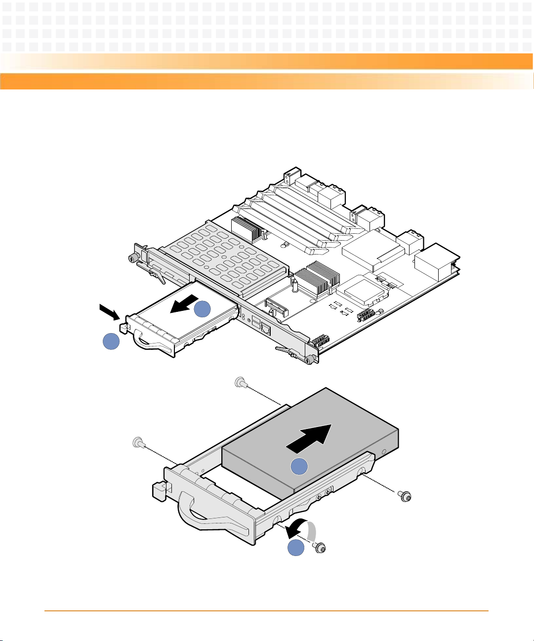
Hardware Installation of ATCA-7150
After replacement, check whether the ATCA-7150 can be powered on and work normally and
1
2
3
4
whether the data in the hard disk can be read and written normally.
Figure 3-7 Removing the Hard Disk
90
ATCA-7150 and RTM-ATCA-7150 Getting Started (6806800G42B)
Page 91

Hardware Installation of ATCA-7150
3.7 Installing and Removing the Blade
3.7.1 Installation
RTM-ATCA-7150 must be installed before the ATCA-7150 to avoid product damage. For
information on how to install the RTM-ATCA-7150, refer to Chapter 2, Installation of the RTM-
ATCA-7150, on page 35
3.7.1.1 Installing the ATCA-7150 in a Powered Shelf
The following procedure describes the installation of the blade. It assumes that your system is
powered and if applicable the RTM is installed. If your system is unpowered, you can disregard
the blue LED and thus skip the respective step. In this case it is a purely mechanical installation.
1. Wear the ESD-preventive wrist strap.
For details, see Wearing the ESD-Preventive Wrist Strap on page 75
2. Take the ATCA-7150 out of the antistatic package.
3. Fully open the upper and lower ejector handles.
4. Slide the ATCA-7150 along the guide rails until the positioning pins of the ATCA-7150 are
inserted in the positioning holes in the shelf, as shown in Figure 3-8.
5. Make sure that the upper and lower ejector handles are attached to the beam properly.
Close the upper and lower ejector handles until the inner sides of the ejector handles are
attached to the face plate, as shown in Figure 3-8. After closing the handles, the blue LED,
OOS and HEALTHY LEDs blink. When payload is powered on, the blue LED is continously
illuminated, and the OOS and HEALTHY LEDs are out.
ATCA-7150 and RTM-ATCA-7150 Getting Started (6806800G42B)
91
Page 92

Hardware Installation of ATCA-7150
6. User the screwdriver to clockwise fasten the screws to fix the ATCA-7150, as shown in
2
1
3
3
2
Figure 3-8.
7. Fully open the ejector handles and the ATCA-7150 is ready for power-on. Before you power
on the ATCA-7150, connect the required external cables and check that the ATCA-7150 is
installed properly.
Figure 3-8 Installing the ATCA-7150
3.7.1.2 Checking the Installation
After you install the RTM of the server blade and the ATCA-7150, and connect and bind cables,
check whether:
z The ATCA-7150 and RTM are installed in the paired slots.
z The upper and lower ejector handles of the RTM are fully closed.
92
ATCA-7150 and RTM-ATCA-7150 Getting Started (6806800G42B)
Page 93

Hardware Installation of ATCA-7150
z The cables are properly connected.
z The cables are well bound.
3.7.1.3 Power-On
The RTM of the server blade is powered by the ATCA-7150 in the slot paired with the RTM
slot. The RTM of the server blade does not support hot swap. Therefore, the RTM must be
installed in the slot before the ATCA-7150 is installed in the paired slot.
3.7.1.3.1 Checks Before Power-On
Before power-on, you need to confirm that:
z The RTM of the server blade and SMM are installed properly.
z The shelf and SMM are powered on properly.
z The required external cables are connected.
z The upper and lower ejector handles of the ATCA-7150 are opened.
3.7.1.3.2 Procedure
To power on the ATCA-7150, proceed as follows:
1. Wear the ESD-preventive wrist strap.
For details, see Wearing the ESD-Preventive Wrist Strap on page 75.
ATCA-7150 and RTM-ATCA-7150 Getting Started (6806800G42B)
93
Page 94

Hardware Installation of ATCA-7150
2. Close the upper and lower ejector handles.
The HOTSWAP LED blinks at the short blink rate. The OOS and HEALTHY LEDs blink for 10
times at the same time. When the OOS and HOTSWAP LEDs are off and the HEALTHY LED
is on (green), the ATCA-7150 is powered on properly.
During power-on, if the HEALTHY LED blinks (red), an alarm occurs to the ATCA-7150.
3.7.2 Removal
z Before you remove an ATCA-7150 or RTM of the server blade, prepare packing materials,
such as an antistatic package.
z Before you remove an ATCA-7150 or RTM of the server blade, power off the ATCA-7150.
For details on how to power off the ATCA-7150, see Power Off on page 94.
3.7.2.1 Power Off
The RTM of the server blade is powered by the ATCA-7150 in the slot paired with the RTM
slot. The RTM of the server blade does not support hot swap. You can remove the RTM only
when the ATCA-7150 is powered off and removed from the slot.
94
ATCA-7150 and RTM-ATCA-7150 Getting Started (6806800G42B)
Page 95

Hardware Installation of ATCA-7150
3.7.2.1.1 Checks Before Power-Off
Before power-off, you need to confirm that:
z Data has been saved on the ATCA-7150.
z No application runs on the ATCA-7150.
z The ATCA-7150 has quitted the operating system (OS).
3.7.2.1.2 Procedure
To power off the ATCA-7150, proceed as follows:
1. Wear the ESD-preventive wrist strap.
For details, see Wearing the ESD-Preventive Wrist Strap on page 75.
2. Open the upper and lower ejector handles.
The ATCA-7150 is powered off properly when:
z The HOTSWAP LED blinks at the short blink rate and then is on (blue).
z The OOS LED is on (red or amber).
z The HEALTHY LED is off.
3.7.2.2 Removing the ATCA-7150
To remove the ATCA-7150, proceed as follows:
1. Wear the ESD-preventive wrist strap.
For details, see Wearing the ESD-Preventive Wrist Strap on page 75.
2. Open the upper and lower ejector handles to power off the ATCA-7150, as shown in Figure
3-9.
For details, see Power Off on page 94.
3. Use the screwdriver to unfasten the captive screws anticlockwise, as shown in Figure 3-9.
ATCA-7150 and RTM-ATCA-7150 Getting Started (6806800G42B)
95
Page 96

Hardware Installation of ATCA-7150
4. Remove the ATCA-7150 along the guide rails, as shown in Figure 3-9.
1
1
2
2
3
5. Place the ATCA-7150 in the antistatic package.
Figure 3-9 Removing the ATCA-7150
3.8 Ejector Handles
The ATCA-7150 supports hot swap. As shown in Figure 3-3, the face plate of the ATCA-7150
provides an upper and a lower ejector handles. The ejector handles help to insert, remove,
power on, and power off the ATCA-7150.
Insertion and Removal
96
ATCA-7150 and RTM-ATCA-7150 Getting Started (6806800G42B)
Page 97

Hardware Installation of ATCA-7150
Table 3-7 describes the insertion and removal of the ATCA-7150 by using the ejector handles.
Table 3-7 Insertion and Removal of the ATCA-7150
Operation Description
Insert the ATCA-7150 The process for inserting the ATCA-7150 is as follows:
z When the ejector handles are not closed, the HOTSWAP LED is on
and the ATCA-7150 is not powered on.
z After the ejector handles are closed, the HOTSWAP LED blinks at the
long blink rate and the ATCA-7150 requests for activation.
z After activation, the ATCA-7150 is powered on and the HOTSWAP
LED is off.
Remove the ATCA-7150 The process for removing the ATCA-7150 is as follows:
z When you open the ejector handles, the HOTSWAP LED blinks at the
short blink rate and the ATCA-7150 requests for deactivation.
z After deactivation, the ATCA-7150 is ready for power-off.
z When the HOTSWAP LED is on, the ATCA-7150 is powered off. At
this time, you can remove the ATCA-7150 by holding the ejector
handles.
Power-On and Power-Off
Table 3-8 describes the power-on and power-off of the ATCA-7150 by using the ejector handles.
Table 3-8 Power-On and Power-Off of the ATCA-7150
Operation Description
Power on theATCA-7150 Whether you close one ejector handle or both ejector handles, the ATCA-
7150 can be powered on and work well.
Power off the ATCA-7150 When both ejector handles are opened, you can power off the ATCA-
7150.
ATCA-7150 and RTM-ATCA-7150 Getting Started (6806800G42B)
97
Page 98

Hardware Installation of ATCA-7150
98
ATCA-7150 and RTM-ATCA-7150 Getting Started (6806800G42B)
Page 99

ATroubleshooting
A.1 Overview
This chapter describes:
z Precautions
z Principles
z Resources
z LED Display Exceptions
z Power-On Startup Exceptions
z OS Exceptions
A.2 Precautions
Appendix: A
Before you remove the faults of the ATCA-7150 and RTM-ATCA-7150 suite, be familiar with
the Server System Safety Information shipped with the shelf.
A.3 Principles
During troubleshooting, follow the principles:
z Diagnose the outside and then the inside.
In troubleshooting, remove the outside faults, such as power interruption and the faults of
the peer device.
z Diagnose the network and then the NEs (network Elements).
According to the network topology, analyze whether the network environment is normal
and the interconnected device is faulty. Locate the NE to which the fault occurs.
z Diagnose the high speed part and then the low speed part.
From the alarm signal stream, the alarm of the high speed signal often causes the alarm of
the low speed signal. Therefore, remove the fault of the high speed part first.
ATCA-7150 and RTM-ATCA-7150 Getting Started (6806800G42B)
99
Page 100

Troubleshooting
z Analyze the alarm of high level and then that of low level.
Analyze the alarm of high level, such as critical alarm or major alarm. Then, analyze the
alarm of low level, such as minor alarm or warning alarm.
A.4 Resources
You can use the following resources for troubleshooting:
z LEDs
The ATCA-7150 suite provides the following LEDs:
— Out of Service (OOS) LED
— In Service (IS) LED
— Attention (ATN) LED
— Hotswap (H/S) LED
— Hard Disk (HDD) LED
In addition, the external GE daughter card provides network port LEDs (for two Ethernet
interfaces). The external FC daughter card provides FC status LEDs (for two FC interfaces).
You can monitor the LEDs to diagnose the current status of the ATCA-7150 suite. For
details on the LEDs of the ATCA-7150 suite, see the LED section in the ATCA-7150
Installation and Use manual.
z Generating error codes and alarm signals
Error codes and alarm signals help you to further locate and remove the faults.
A.5 Contacting Emerson Network Power for
Technical Support
If a problem persists after you handle it under the guidance of this document, contact the local
office or Customer Service Center of Emerson Network Power to obtain timely technical
support. Before you report the problem to Emerson Network Power engineer, collect the
following information:
z Detailed name and address of the customer
z Contact person and telephone number
z Time when the fault occurred
100
ATCA-7150 and RTM-ATCA-7150 Getting Started (6806800G42B)
 Loading...