

Emerson Rosemount 2051, Rosemount 2051CF series Quick Start Manual

Quick Start Guide
00825-0200-4101, Rev FC
September 2016
Rosemount™ 2051 Pressure Transmitter
Rosemount 2051CF Series Flowmeter
with FOUNDATION™ Fieldbus Protocol
Note
Before installing the transmitter, confirm the correct device driver is loaded on the host systems.
See “System readiness” on page 3.

Quick Start Guide
September 2016
NOTICE
This guide provides basic guidelines for Rosemount 2051 Transmitters. It does not provide instructions for
configuration, diagnostics, maintenance, service, troubleshooting, Explosion-Proof, Flame-Proof, or
intrinsically safe (I.S.) installations. Refer to the Rosemount 2051 Reference Manual
This manual is also available electronically on EmersonProcess.com/Rosemount
Explosions could result in death or serious injury.
Installation of this transmitter in an explosive environment must be in accordance with the appropriate local,
national, and international standards, codes, and practices. Review the approvals section of the Rosemount
2051 Reference Manual
In an Explosion-proof/Flameproof installation, do not remove the transmitter covers when power is
applied to the unit.
Process leaks may cause harm or result in death.
To avoid process leaks, only use the o-ring designed to seal with the corresponding flange adapter.
Electrical shock can result in death or serious injury.
Avoid contact with the leads and the terminals. High voltage that may be present on leads can cause
electrical shock.
Conduit/cable entries
Unless marked, the conduit/cable entries in the transmitter housing use a
marked “M20” are M20 ⫻ 1.5 thread form. On devices with multiple conduit entries, all entries will have
the same thread form. Only use plugs, adapters, glands, or conduit with a compatible thread form when
closing these entries.
When installing in a hazardous location, use only appropriately listed or Ex certified plugs, adapters, or
glands in cable/conduit entries.
for any restrictions associated with a safe installation.
for more instruction.
.
1
/2–14 NPT thread form. Entries
Contents
System readiness . . . . . . . . . . . . . . . . . . . . . . . . . 3
Mount the transmitter . . . . . . . . . . . . . . . . . . . . 4
Tagging . . . . . . . . . . . . . . . . . . . . . . . . . . . . . . . . . 8
Housing rotation . . . . . . . . . . . . . . . . . . . . . . . . . 9
Set the switches . . . . . . . . . . . . . . . . . . . . . . . . . . 9
2
Wire, ground, and power up . . . . . . . . . . . . . . 10
Configure . . . . . . . . . . . . . . . . . . . . . . . . . . . . . . 13
Zero trim the transmitter . . . . . . . . . . . . . . . . 19
Product Certifications . . . . . . . . . . . . . . . . . . . 20
September 2016
Quick Start Guide
1.0 System readiness
1.1 Confirm correct device driver
Verify the correct device driver (DD/DTM
ensure proper communications.
Download the correct device driver at your host vendor download site,
EmersonProcess.com or Fieldbus.org.
Rosemount 2051 device revisions and drivers
Table 1 provides the information necessary to ensure you have the correct device
driver and documentation for your device.
Table 1. Rosemount 2051 FOUNDATION Fieldbus Device Revisions and Files
™
) is loaded on your systems to
Device
revision
(1)
2
1
1. FOUNDATION Fieldbus device revision can be read using a FOUNDATION Fieldbus capable configuration tool.
2. Device driver file names use device and DD revision. To access functionality, the correct device driver must be installed on your
control and asset management hosts, and on your configuration tools.
Host Device driver (DD)
All DD4: DD Rev 1 Fieldbus.org
All DD5: DD Rev 1 Fieldbus.org
AMS™ Device Manager
Emerson
Emerson
Emerson 375/475: DD Rev 2 FieldCommunicator.com
All DD4: DD Rev 4 Fieldbus.org
All DD5: NA N/A
Emerson
Emerson 375/475: DD Rev 2 FieldCommunicator.com
V 10.5 or higher:
DD Rev 2
AMS Device Manager
V 8 to 10.5: DD Rev 1
AMS Device Manager
V 8or higher: DD Rev 2
(2)
Obtain at Device driver (DTM)
EmersonProcess.com
EmersonProcess.com
EmersonProcess.com
EmersonProcess.com
EmersonProcess.com
Manual document
number
00809-0200-4101,
Rev BA or newer
00809-0200-4101,
Rev AA
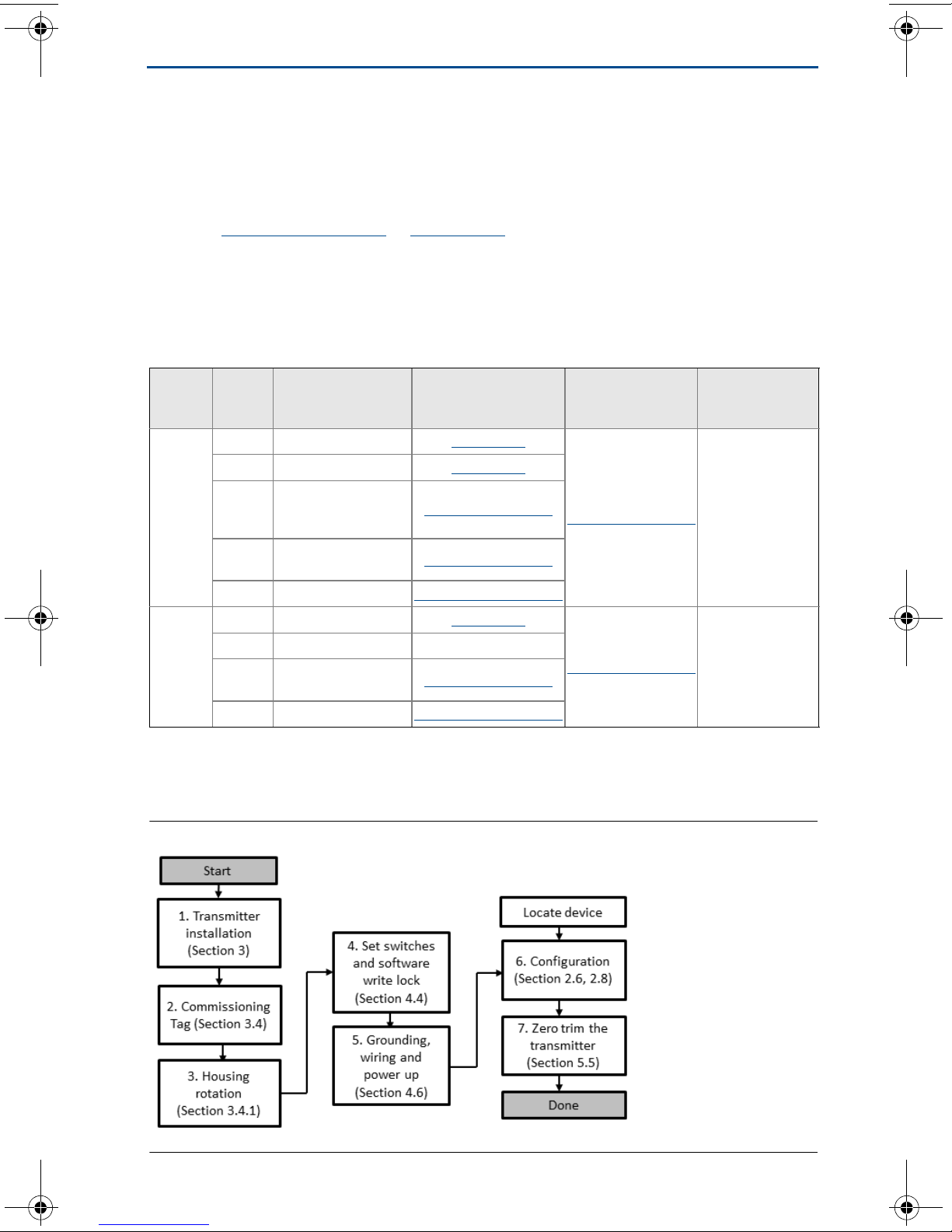
Figure 1. Installation Flowchart
3
Quick Start Guide
2.0 Mount the transmitter
September 2016
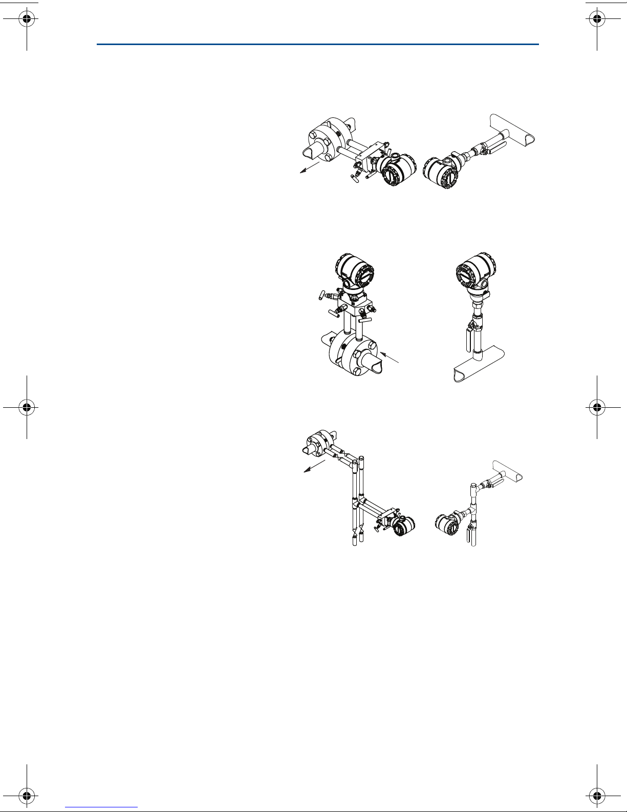
2.1 Liquid applications
1. Place taps to the side of the
line.
2. Mount beside or below the
taps.
3. Mount the transmitter so the
drain/vent valves are oriented
upward.
2.2 Gas applications
1. Place taps in the top or side of
the line.
2. Mount beside or above the
taps.
Coplanar In-line
2.3 Steam applications
1. Place taps to the side of the
line.
2. Mount beside or below the
taps.
3. Fill impulse lines with water.
4
September 2016
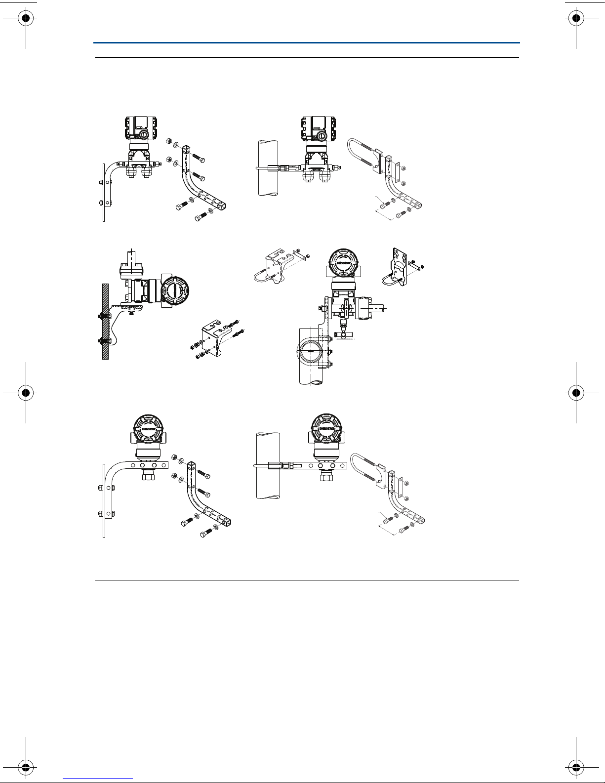
Figure 2. Panel and Pipe Mounting
Panel mount
(1)
Coplanar flange
Traditional flange
Quick Start Guide
Pipe mount
Rosemount 2051T
1. 5/16 ⫻ 11/2 panel bolts are customer supplied.
5
Quick Start Guide
September 2016
2.4 Bolting considerations
If the transmitter installation requires assembly of the process flanges, manifolds,
or flange adapters, follow the assembly guidelines to ensure a tight seal for
optimal performance characteristics of the transmitters. Use only bolts supplied
™
with the transmitter or sold by Emerson
illustrates common transmitter assemblies with the bolt length required for
proper transmitter assembly.
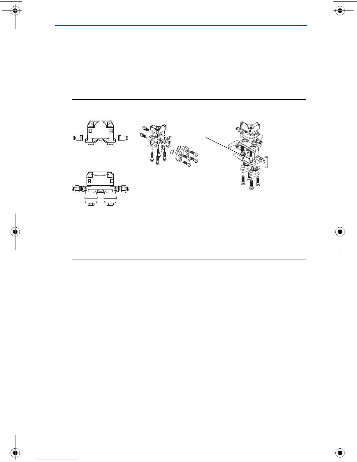
Figure 3. Common Transmitter Assemblies
A
4 × 1.75-in.
(44 mm)
C
as spare parts. Figure 3 on page 6
D
4 × 2.25-in.
(57 mm)
B
4 × 2.88-in.
(73 mm)
A. Transmitter with coplanar flange
B. Transmitter with coplanar flange and optional flange adapters
C. Transmitter with traditional flange and optional flange adapters
D. Transmitter with coplanar flange and optional manifold and flange adapters
4 × 1.75-in.
(44 mm)
4 × 1.50-in.
(38 mm)
4 × 1.75-in.
(44 mm)
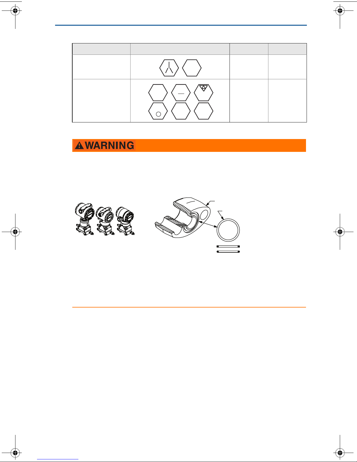
Bolts are typically carbon steel or stainless steel. Confirm the material by viewing
the markings on the head of the bolt and referencing Table 2. If bolt material is
not shown in Table 2, contact a local Emerson Process Management
representative for more information.
Carbon steel bolts do not require lubrication and the stainless steel bolts are
coated with a lubricant to ease installation. However, no additional lubricant
should be applied when installing either type of bolt.
Use the following bolt installation procedure:
1. Finger tighten the bolts.
2. Torque the bolts to the initial torque value using a crossing pattern.
See Ta bl e 2 for initial torque value.
3. Torque the bolts to the final torque value using the same crossing pattern.
See Table 2 for final torque value.
4. Verify the flange bolts are protruding through the sensor module bolt holes
before applying pressure.
6
September 2016
B7M
A
B
Rosemount 3051S/3051/2051
C
D
Table 2. Torque Values for the Flange and Flange Adapter Bolts
Bolt material Head markings Initial torque Final torque
Carbon Steel (CS) 300 in-lb 650 in-lb
Quick Start Guide
316
Stainless Steel (SST) 150 in-lb 300 in-lb
316
R
B8M
STM
316
316
SW
316
2.5 O-rings with flange adapters
Failure to install proper flange adapter O-rings may cause process leaks, which can result in death or
serious injury. The two flange adapters are distinguished by unique O-ring grooves. Only use the O-ring
that is designed for its specific flange adapter, as shown below:
O-ring location
A. Flange adapter
B. O-ring
C. PTFE based (profile is square)
D. Elastomer (profile is round)
Whenever the flanges or adapters are removed, visually inspect the O-rings. Replace them if there are
any signs of damage, such as nicks or cuts. If you replace the O-rings, re-torque the flange bolts and
alignment screws after installation to compensate for seating of the PTFE O-ring.
2.6 Environmental seal for housing
Thread sealing (PTFE) tape or paste on male threads of conduit is required to
provide a water/dust tight conduit seal and meets requirements of NEMA®
Type 4X, IP66, and IP68. Consult factory if other Ingress Protection ratings are
required.
For M20 threads, install conduit plugs to full thread engagement or until
mechanical resistance is met.
2.7 In-line gage transmitter orientation
The low side pressure port (atmospheric reference) on the in-line gage
transmitter is located in the neck of the transmitter, behind the housing.
The vent path is 360° around the transmitter between the housing and sensor.
(See Figure 4.)
7

Quick Start Guide
September 2016
Keep the vent path free of any obstruction, including but not limited to paint,
dust, and lubrication by mounting the transmitter so fluids can drain away.
Figure 4. In-line Gage Low Side Pressure Port
A
A. Pressure port location
3.0 Tagging
3.1 Commissioning (paper) tag
To identify which device is at a particular location use the removable tag provided
with the transmitter. Ensure the physical device tag (PD tag field) is properly
entered in both places on the removable commissioning tag and tear off the
bottom portion for each transmitter.
Note
The device description loaded in the host system must be at the same revision as this
device, see “System readiness” on page 3.
Figure 5. Commissioning Tag
Commissioning Tag
DEVICE ID:
0011512051010001440-12169809172
DEVICE REVISION: 1.1
PHYSICAL DEVICE TAG
DEVICE ID:
0011512051010001440 -12169809172
Device Barcode
DEVICE REVISION: 1.1
S / N :
PHYSICAL DEVICE TAG
A
Commissioning Tag
DEVICE ID:
001151AC00010001440-12169809172
DEVICE REVISION: 2.1
PHYSICAL DEVICE TAG
DEVICE ID:
001151AC00010001440-12169 809172
Device Barcode
DEVICE REVISION: 2.1
S / N :
PHYSICAL DEVICE TAG
A. Device revision
8
September 2016
A
Note
The device description loaded in the host system must be at the same revision as this
device. The device description can be downloaded from the host system website or
EmersonProcess.com/Rosemount
Quick Links. You can also visit Fieldbus.org and select End User Resources.
by selecting Download Device Drivers under Product
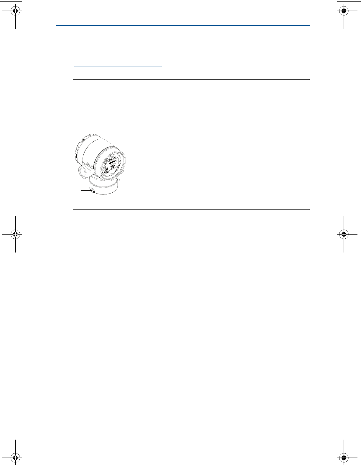
4.0 Housing rotation
To improve field access to wiring or to better view the optional LCD display:
Figure 6. Housing Rotation
Quick Start Guide
A. Housing rotation set screw (5/64-in.)
1. Loosen the housing rotation set screw.
2. First rotate the housing clockwise to the desired location.
3. If the desired location cannot be achieved due to thread limit, rotate the
housing counter clockwise to the desired location (up to 360° from thread
limit).
4. Re-tighten the housing rotation set screw to no more than 7 in-lb when
desired location is reached.
5.0 Set the switches
Set simulate and security switch configuration before installation as shown in
Figure 7.
The simulate switch enables or disables simulated alerts and simulated AI
Block status and values. The default simulate switch position is enabled.
The security switch allows (unlocked symbol) or prevents (locked symbol) any
configuration of the transmitter.
- Default security is off (unlocked symbol).
- The security switch can be enabled or disabled in software.
Use the following procedure to change the switch configuration:
1. If the transmitter is installed, secure the loop, and remove power.
2. Remove the housing cover opposite the field terminal side. Do not remove the
instrument cover in explosive atmospheres when the circuit is live.
3. Slide the security and simulate switches into the preferred position.
4. Replace the housing cover.
9
Quick Start Guide
C
B
A
D
E
F
Note
It is recommended the cover be tightened until there is no gap between the cover and
housing.
Figure 7. Simulate and Security Switches
September 2016
A. Simulate disabled position
B. Simulate switch
C. Simulate enabled position (default)
D. Security locked position
E. Security switch
F. Security unlocked position (default)
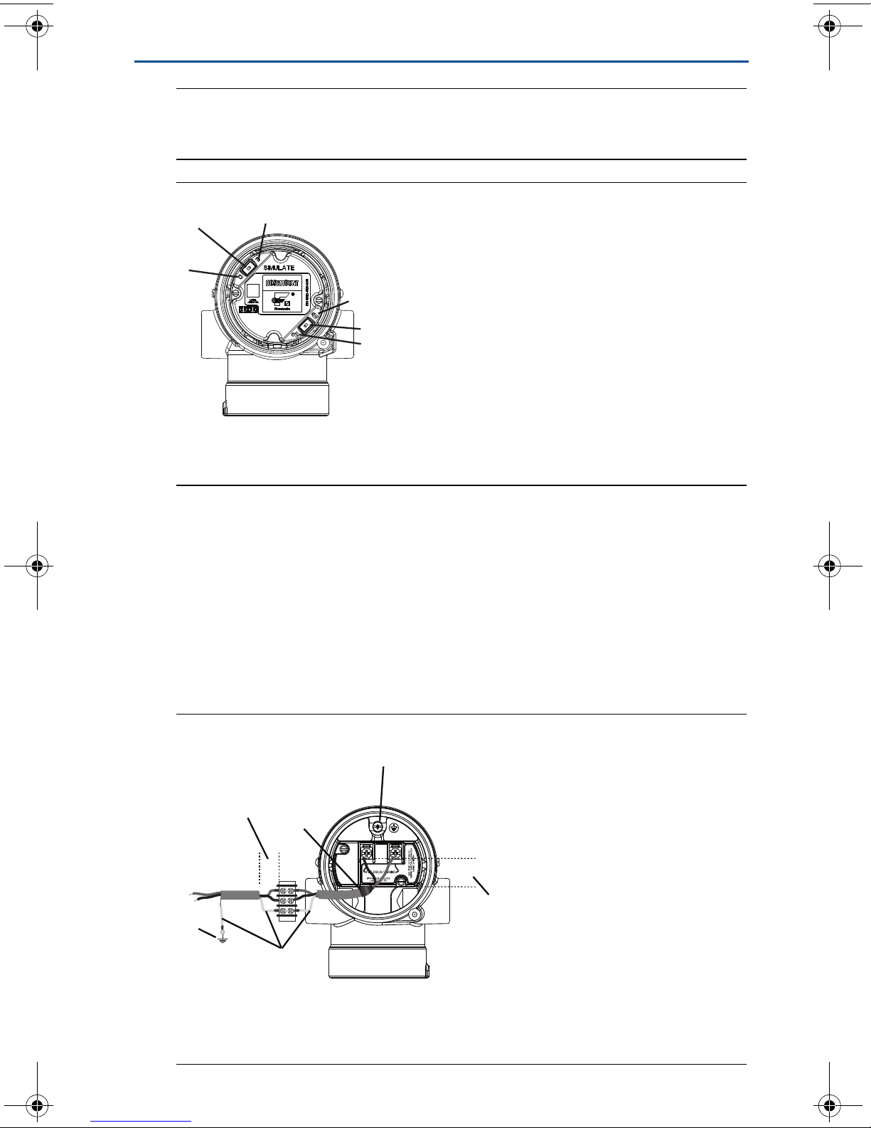
6.0 Wire, ground, and power up
Use of copper wire of sufficient size to ensure that the voltage across the
transmitter power terminals does not drop below 9 Vdc. Power supply voltage
can be variable, especially under abnormal conditions such as when operating on
battery backup. A minimum of 12 Vdc under normal operating conditions is
recommended. Shielded twisted pair Type A cable is recommended.
1. To power the transmitter, connect the power leads to the terminals indicated
on the terminal block label.
Figure 8. Wiring Terminals
C
A
B
F
DP
D
A. Minimize distance
B. Trim shield and insulate
C. Protective grounding terminal
(do not ground cable shield at the transmitter)
10
E
D. Insulate shield
E. Minimize distance
F. Connect shield back to the power
supply ground

September 2016
Quick Start Guide
Note
The Rosemount 2051 power terminals are polarity insensitive, which means the electrical
polarity of the power leads does not matter when connecting to the power terminals. If
polarity sensitive devices are connected to the segment, terminal polarity should be
followed. When wiring to the screw terminals, the use of crimped legs is recommended.
2. Ensure full contact with terminal block screw and washer. When using a direct
wiring method, wrap wire clockwise to ensure it is in place when tightening
the terminal block screw. No additional power is needed.
Note
The use of a pin or a ferrule wire terminal is not recommended as the connection may be
more susceptible to loosening over time or under vibration.
6.1 Signal wiring grounding
Do not run signal wiring in conduit or open trays with power wiring, or near heavy
electrical equipment. Grounding terminations are provided on the outside of the
electronics housing and inside the terminal compartment. These grounds are
used when transient protect terminal blocks are installed or to fulfill local
regulations.
1. Remove the field terminals housing cover.
2. Connect the wiring pair and ground as indicated in Figure 8.
a. Trim the cable shield as short as practical and insulate from touching the
transmitter housing.
Note
Do NOT ground the cable shield at the transmitter; if the cable shield touches the
transmitter housing, it can create ground loops and interfere with communications.
b. Continuously connect the cable shields to the power supply ground.
c. Connect the cable shields for the entire segment to a single good earth
ground at the power supply.
Note
Improper grounding is the most frequent cause of poor segment communications.
3. Replace the housing cover. It is recommended that the cover be tightened
until there is no gap between the cover and the housing.
4. Plug and seal unused conduit connections.
6.2 Power supply
The transmitter requires between 9 and 32 Vdc (9 and 30 Vdc for intrinsic safety,
and 9 and 17.5 Vdc for FISCO intrinsic safety) to operate and provide complete
functionality.
11
 Loading...