

Page 1
Quick Start Guide
00825-0600-4101, Rev CA
March 2020
Rosemount™ 2051 Pressure Transmitter
and Rosemount 2051CF Series Flow
Meter
with FOUNDATION™ Fieldbus Protocol
Page 2

Quick Start Guide March 2020
Contents
About this guide .......................................................................................................................... 3
System readiness......................................................................................................................... 5
Mount the transmitter..................................................................................................................7
Tagging......................................................................................................................................14
Housing rotation........................................................................................................................ 15
Set the switches......................................................................................................................... 16
Wire, ground, and power up.......................................................................................................18
Configure................................................................................................................................... 21
Zero trim the transmitter........................................................................................................... 28
Product certifications................................................................................................................. 29
2
Page 3

March 2020 Quick Start Guide
1 About this guide
This guide provides basic guidelines for Rosemount 2051 Pressure
Transmitters. It does not provide instructions for configuration, diagnostics,
maintenance, service, troubleshooting, Explosion-proof, Flameproof, or
intrinsically safe (I.S.) installations. Refer to Rosemount 2051 Reference
Manual for more instructions. This guide is also available electronically at
Emerson.com/Rosemount.
1.1 Safety messages
WARNING
Explosions could result in death or serious injury.
Installation of these transmitters in an explosive environment must be in
accordance with the appropriate local, national, and international standards,
codes, and practices. Review the approvals section of the Rosemount 2051
Reference Manual for any restrictions associated with a safe installation.
In an explosion-proof/flameproof installation, do not remove the transmitter
covers when power is applied to the unit.
Process leaks could result in death or serious injury.
To avoid process leaks, only use the O-ring designed to seal with the
corresponding flange adapter.
Electrical shock could cause death or serious injury.
Avoid contact with the leads and terminals. High voltage that may be
present on leads can cause electrical shock.
Conduit/cable entries
Unless marked, the conduit/cable entries in the transmitter housing use a
½–14 NPT thread form. Entries marked “M20” are M20 × 1.5 thread form.
On devices with multiple conduit entries, all entries will have the same
thread form. Only use plugs, adapters, glands, or conduit with a compatible
thread form when closing these entries.
Quick Start Guide 3
Page 4

Quick Start Guide March 2020
WARNING
Physical access
Unauthorized personnel may potentially cause significant damage to and/or
misconfiguration of end users’ equipment. This could be intentional or
unintentional and needs to be protected against.
Physical security is an important part of any security program and
fundamental to protecting your system. Restrict physical access by
unauthorized personnel to protect end users’ assets. This is true for all
systems used within the facility.
4
Page 5

March 2020 Quick Start Guide
2 System readiness
2.1 Confirm correct device driver
• Verify the correct device driver (DD/DTM™) is loaded on your systems to
ensure proper communications.
• Download the correct device driver at your host vendor download site,
Emerson.com or Fieldbus.org.
2.1.1 Device revisions and drivers
Table 2-1 provides the information necessary to ensure you have the correct
device driver and documentation for your device.
Table 2-1: Rosemount 2051 FOUNDATION Fieldbus Device Revisions and
Files
Device
revision
(1)
2 All DD4: DD
1 All DD4: DD
Host Device
All DD5: DD
Emerson AMS Device
Emerson AMS Device
Emerson 375/475:
All DD5: NA N/A
Emerson AMS Device
driver
(2)
(DD)
Rev 1
Rev 1
Manager V
10.5 or
higher: DD
Rev 2
Manager V
8 to 10.5:
DD Rev 1
DD Rev 2
Rev 4
Manager V
8 or higher:
DD Rev 2
Obtain at Device driver
(DTM)
Fieldbus.org Emerson.com 00809-0200-
Fieldbus.org
Emerson.com
Emerson.com
FieldCommun
icator.com
Fieldbus.org Emerson.com 00809-0200-
Emerson.com
Reference
document
4101,
Rev BA or
newer
4101,
Rev AA
Quick Start Guide 5
Page 6
Quick Start Guide March 2020
Table 2-1: Rosemount 2051 FOUNDATION Fieldbus Device Revisions and
Files (continued)
Device
revision
(1)
Host Device
driver
(2)
(DD)
Emerson 375/475:
DD Rev 2
Obtain at Device driver
(DTM)
FieldCommun
icator.com
Reference
document
(1) FOUNDATION Fieldbus device revision can be read using a FOUNDATION Fieldbus
capable configuration tool.
(2) Device driver file names use device and DD revision. To access functionality, the
correct device driver must be installed on your control and asset management
hosts, and on your configuration tools.
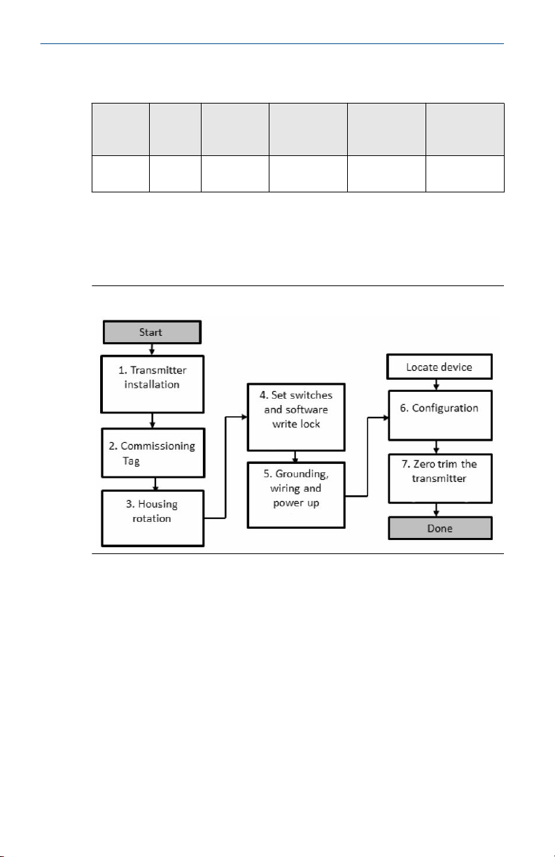
Figure 2-1: Installation Flowchart
6
Page 7
March 2020 Quick Start Guide
3 Mount the transmitter
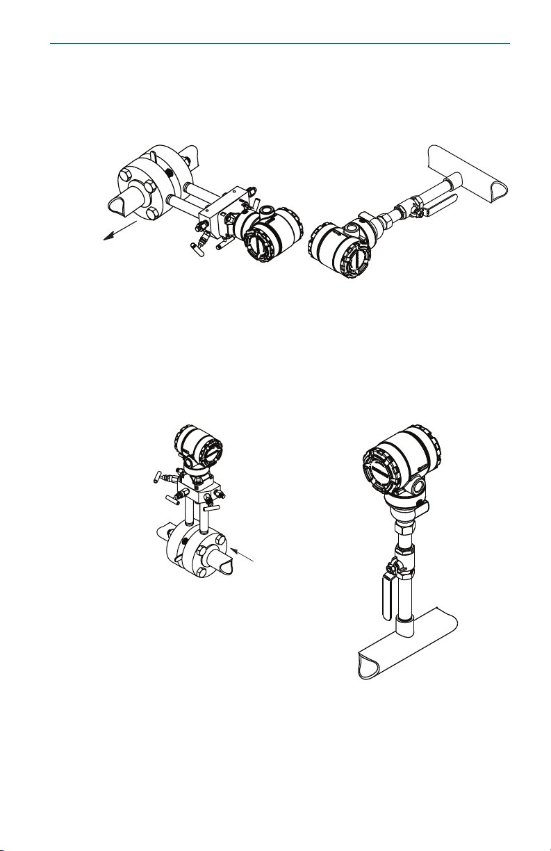
3.1 Liquid applications
Procedure
1. Place taps to the side of the line.
2. Mount beside or below the taps.
3. Mount the transmitter so the drain/vent valves are oriented upward.
3.2 Gas applications
Procedure
1. Place taps in the top or side of the line.
2. Mount beside or above the taps.
Quick Start Guide 7
Page 8
Quick Start Guide March 2020
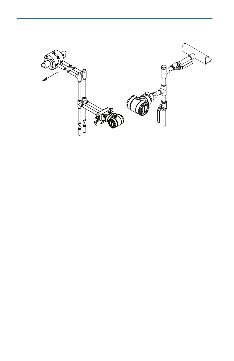
3.3 Steam applications
Procedure
1. Place taps to the side of the line.
2. Mount beside or below the taps.
3. Fill impulse lines with water.
8
Page 9
March 2020 Quick Start Guide
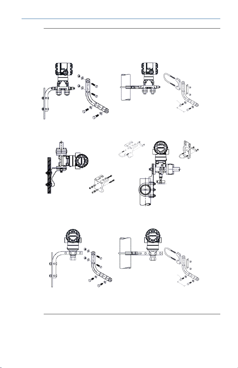
Figure 3-1: Panel and Pipe Mounting
Panel mount
Coplanar flange
Traditional flange
(1)
Pipe mount
Rosemount 2051T
(1) × 1 panel bolts are customer supplied.
Quick Start Guide 9
Page 10
A
4 × 1.75-in.
(44 mm)
D
4 × 1.75-in.
(44 mm)
4 × 2.25-in.
(57 mm)
C
4 × 1.75-in.
(44 mm)
4
× 1.50-in.
(38 mm)
B
4 × 2.88-in.
(73 mm)
Quick Start Guide March 2020
3.4 Bolting considerations
If the transmitter installation requires assembly of the process flanges,
manifolds, or flange adapters, follow the assembly guidelines to ensure a
tight seal for optimal performance characteristics of the transmitters. Use
only bolts supplied with the transmitter or sold by Emerson as spare parts.
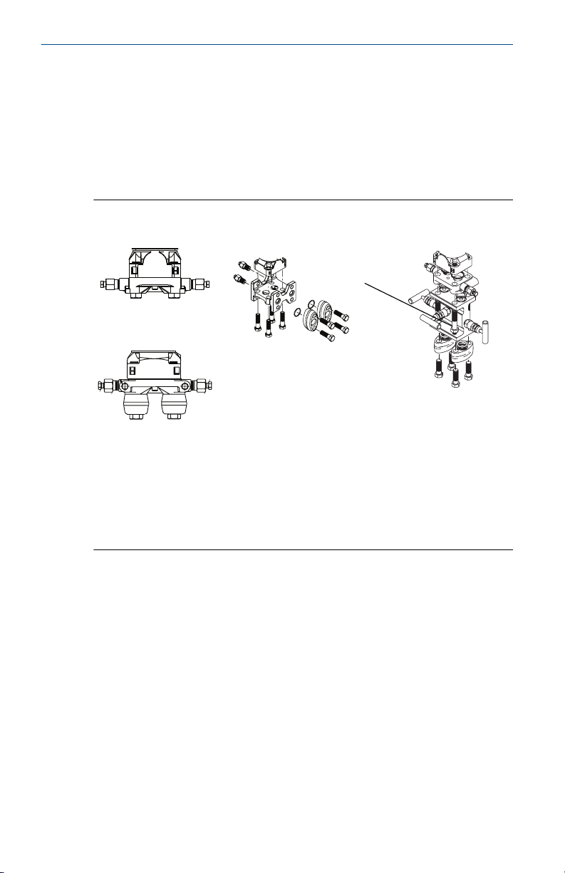
Figure 3-2 illustrates common transmitter assemblies with the bolt length
required for proper transmitter assembly.
Figure 3-2: Common Transmitter Assemblies
10
A. Transmitter with coplanar flange
B. Transmitter with coplanar flange and optional flange adapters
C. Transmitter with traditional flange and optional flange adapters
D. Transmitter with coplanar flange and optional manifold and flange
adapters
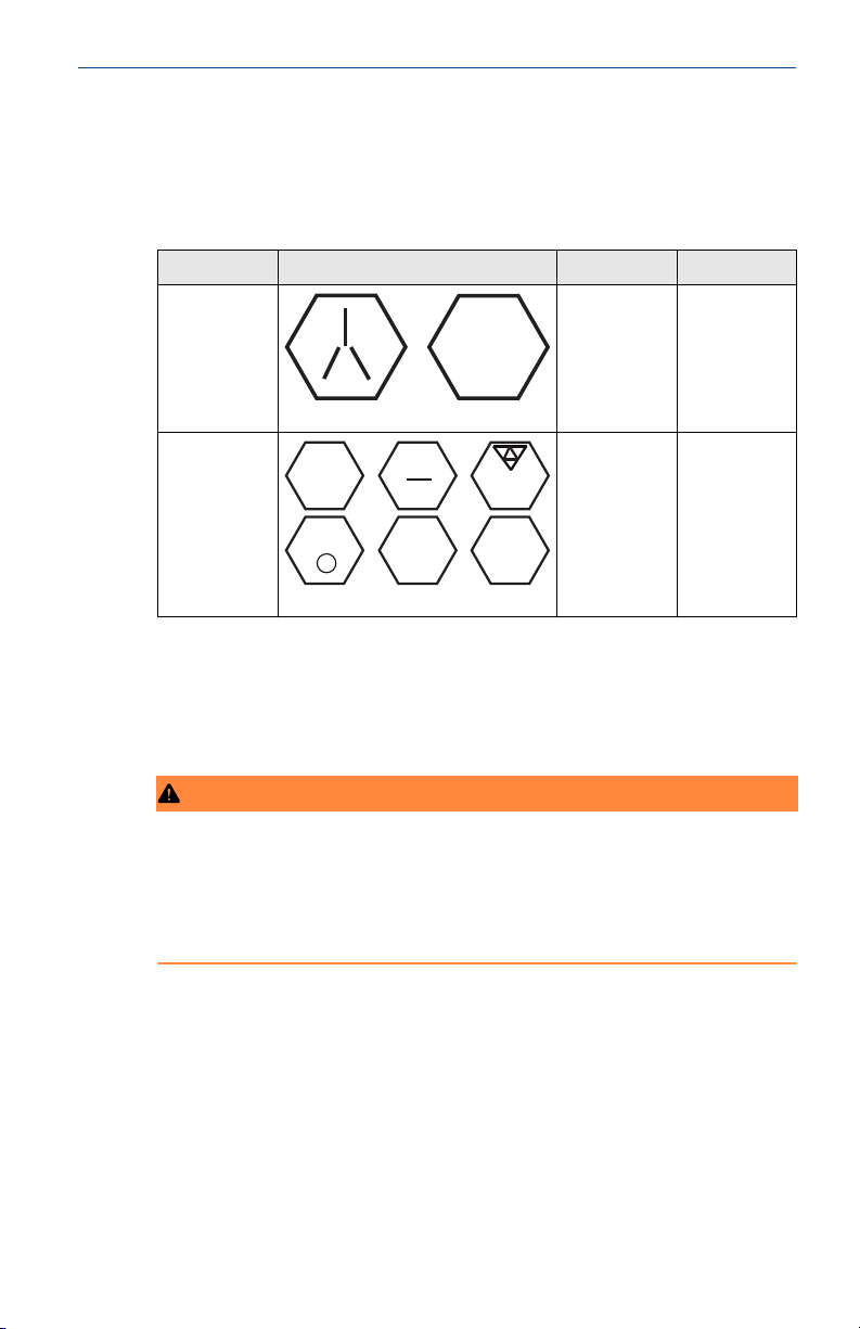
Bolts are typically carbon steel (CS) or stainless steel (SST). Confirm the
material by viewing the markings on the head of the bolt and referencing
Table 3-1. If bolt material is not shown in Table 3-1, contact a local Emerson
representative for more information.
Carbon steel bolts do not require lubrication and the stainless steel bolts are
coated with a lubricant to ease installation. However, no additional lubricant
should be applied when installing either type of bolt.
Use the following bolt installation procedure:
Procedure
1. Tighten the bolts by hand.
2. Torque the bolts to the initial torque value using a crossing pattern.
See Table 3-1 for initial torque value.
Page 11
B7M
316
316
316
SW
316
STM
316
R
B8M
March 2020 Quick Start Guide
3. Torque the bolts to the final torque value using the same crossing
pattern. See Table 3-1 for final torque value.
4. Verify the flange bolts are protruding through the sensor module
bolt holes before applying pressure.
Table 3-1: Torque Values for the Flange and Flange Adapter Bolts
Bolt material Head markings Initial torque Final torque
CS
SST
300 in-lb 650 in-lb
150 in-lb 300 in-lb
3.5 O-rings
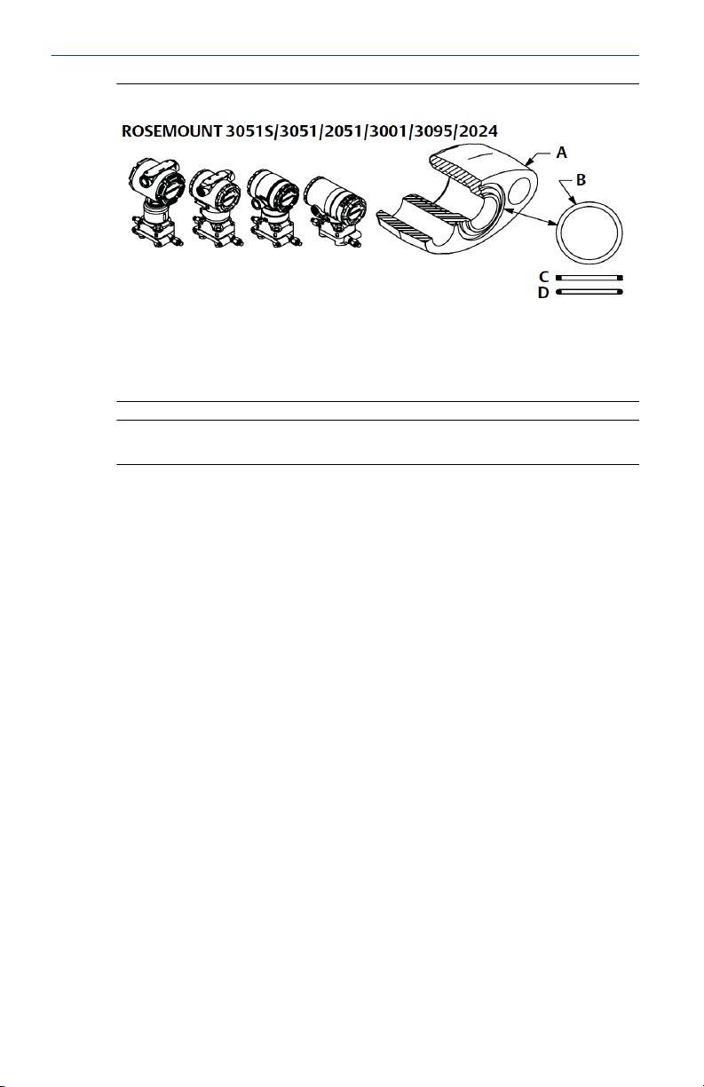
The two styles of Rosemount flange adapters (Rosemount
3051/2051/2024/3095) each require a unique O-ring (see Figure 3-3). Use
only the O-ring designed for the corresponding flange adapter.
WARNING
Failure to install proper flange adapter O-rings may cause process leaks,
which can result in death or serious injury. The two flange adapters are
distinguished by unique O-ring grooves. Only use the O-ring that is designed
for its specific flange adapter, as shown below. When compressed, PTFE Orings tend to cold flow, which aids in their sealing capabilities.
Quick Start Guide 11
Page 12
Quick Start Guide March 2020
Figure 3-3: O-rings
A. Flange adapter
B. O-ring
C. PFTE based
D. Elastomer
Note
You should replace PTFE O-rings if you remove the flange adapter.
3.6 Environmental seal for housing
Thread sealing (PTFE) tape or paste on male threads of conduit is required to
provide a water/dust tight conduit seal and meets requirements of NEMA
Type 4X, IP66, and IP68. Consult factory if other Ingress Protection ratings
are required.
For M20 threads, install conduit plugs to full thread engagement or until
mechanical resistance is met.
®
3.7
12
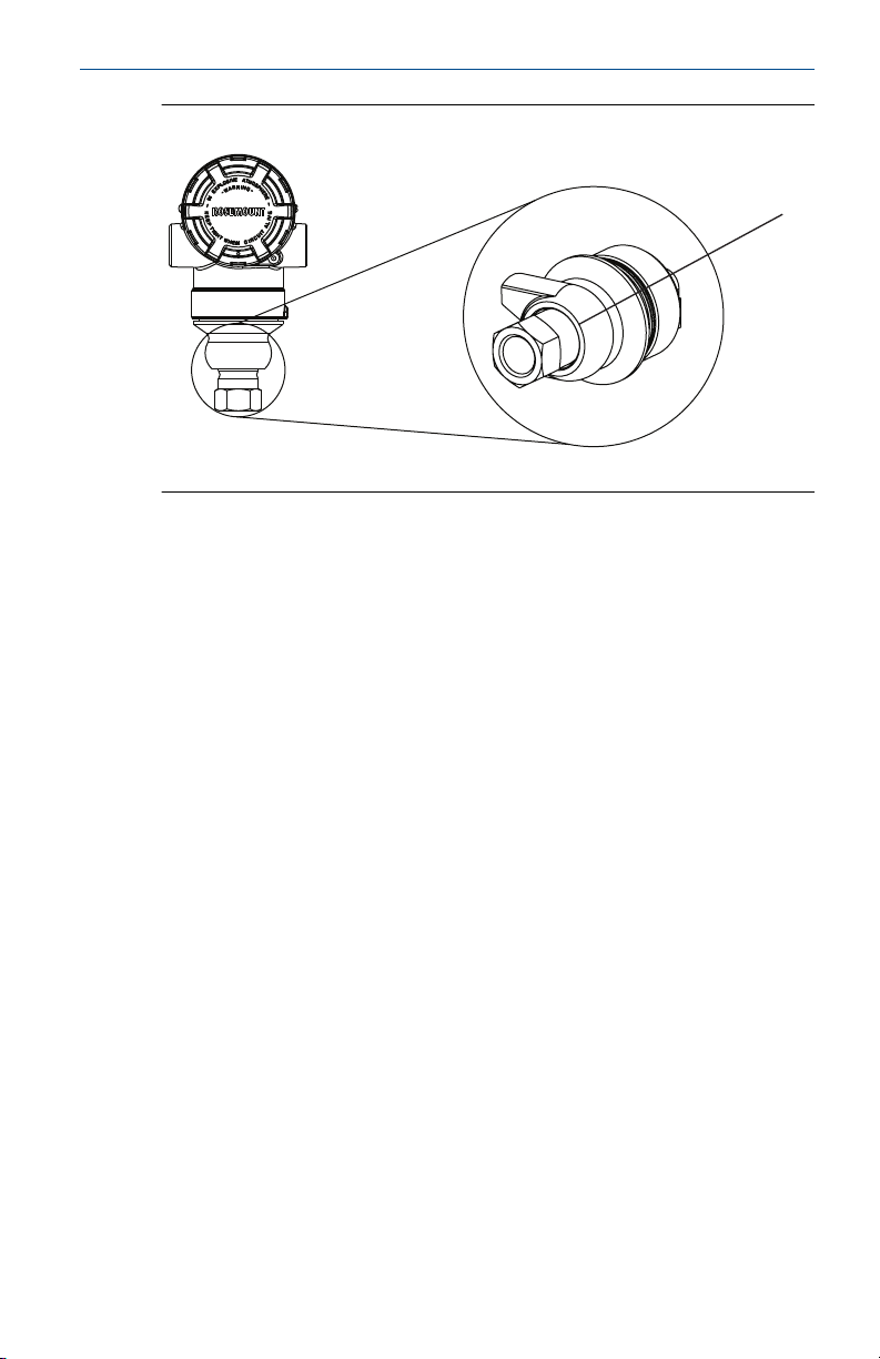
In-line gage transmitter orientation
The low side pressure port (atmospheric reference) on the in-line gage
transmitter is located in the neck of the transmitter, behind the housing. The
vent path is 360° around the transmitter between the housing and sensor.
(See Figure 3-4.)
Keep the vent path free of any obstruction, including but not limited to
paint, dust, and lubrication by mounting the transmitter so fluids can drain
away.
Page 13
A
March 2020 Quick Start Guide
Figure 3-4: In-line Gage Low Side Pressure Port
A. Pressure port location
Quick Start Guide 13
Page 14
Quick Start Guide March 2020
4 Tagging
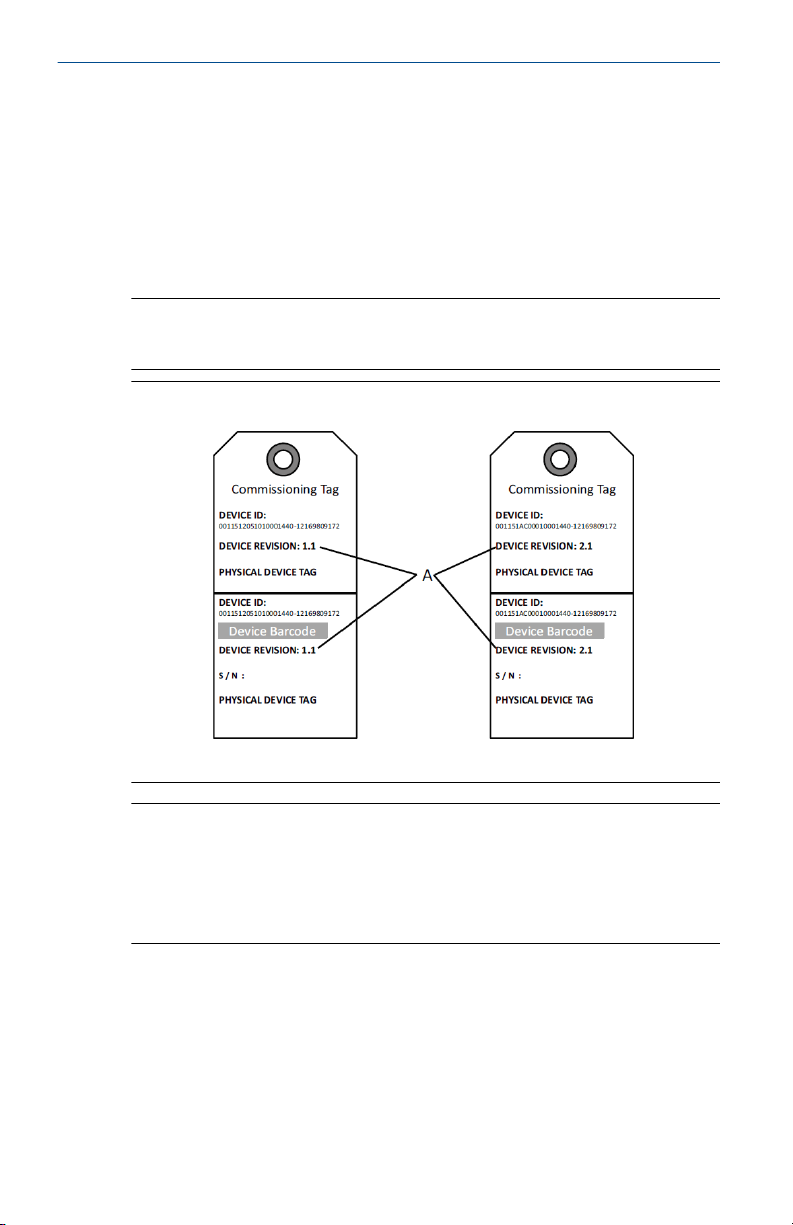
4.1 Commissioning (paper) tag
To identify which device is at a particular location use the removable tag
provided with the transmitter. Ensure the physical device tag (PD tag field) is
properly entered in both places on the removable commissioning tag and
tear off the bottom portion for each transmitter.
Note
The device description loaded in the host system must be at the same
revision as this device.
Figure 4-1: Commissioning Tag
14
A. Device revision
Note
The device description loaded in the host system must be at the same
revision as this device. The device description can be downloaded from the
host system website or Emerson.com/Rosemount by selecting Download
Device Drivers under Product Quick Links. You can also visit Fieldbus.org and
select End User Resources.
Page 15

A
March 2020 Quick Start Guide
5 Housing rotation
To improve field access to wiring or to better view the optional LCD display
follow the procedure steps.
Figure 5-1: Housing Rotation
A. Housing rotation set screw (5/64 in.)
Procedure
1. Loosen the housing rotation set screw using a 5/64 -in. hex wrench.
2. Rotate the housing clockwise to the desired location.
3. If the desired location cannot be achieved due to thread limit, rotate
the housing counterclockwise to the desired location (up to 360°
from thread limit).
4. Retighten the housing rotation set screw to no more than 7 in-lbs
when desired location is reached.
Quick Start Guide 15
Page 16

Quick Start Guide March 2020
6 Set the switches
Set simulate and security switch configuration before installation as shown
in Figure 6-1.
• The simulate switch enables or disables simulated alerts and simulated
AI Block status and values. The default simulate switch position is
enabled.
• The security switch allows (unlocked symbol) or prevents (locked
symbol) any configuration of the transmitter.
• Default security is off (unlocked symbol).
• The security switch can be enabled or disabled in software.
Use the following procedure to change the switch configuration:
Procedure
1. If the transmitter is installed, secure the loop, and remove power.
2. Remove the housing cover opposite the field terminal side. Do not
remove the instrument cover in explosive atmospheres when the
circuit is live.
3. Slide the security and simulate switches into the preferred position.
4. Replace the housing cover.
16
Note
It is recommended the cover be tightened until there is no gap
between the cover and housing.
Page 17

March 2020 Quick Start Guide
Figure 6-1: Simulate and Security Switches
A. Simulate disabled position
B. Simulate switch
C. Simulate enabled position (default)
D. Security locked position
E. Security switch
F. Security unlocked position (default)
Quick Start Guide 17
Page 18

DP
A
B
C
F
D
E
Quick Start Guide March 2020
7 Wire, ground, and power up
Use of copper wire of sufficient size to ensure that the voltage across the
transmitter power terminals does not drop below 9 Vdc. Power supply
voltage can be variable, especially under abnormal conditions such as when
operating on battery backup. A minimum of 12 Vdc under normal operating
conditions is recommended. Shielded twisted pair Type A cable is
recommended.
Procedure
1. To power the transmitter, connect the power leads to the terminals
indicated on the terminal block label.
Figure 7-1: Wiring Terminals
A. Minimize distance
B. Trim shield and insulate
C. Protective grounding terminal (do not ground cable shield at the
transmitter)
D. Insulate shield
E. Minimize distance
F. Connect shield back to the power supply ground
18
Page 19

March 2020 Quick Start Guide
Note
The Rosemount 2051 power terminals are polarity insensitive, which
means the electrical polarity of the power leads does not matter
when connecting to the power terminals. If polarity sensitive devices
are connected to the segment, terminal polarity should be followed.
When wiring to the screw terminals, the use of crimped legs is
recommended.
2. Ensure full contact with terminal block screw and washer. When
using a direct wiring method, wrap wire clockwise to ensure it is in
place when tightening the terminal block screw. No additional power
is needed.
Note
The use of a pin or a ferrule wire terminal is not recommended as the
connection may be more susceptible to loosening over time or under
vibration.
7.1 Signal wiring grounding
Do not run signal wiring in conduit or open trays with power wiring, or near
heavy electrical equipment. Grounding terminations are provided on the
outside of the electronics housing and inside the terminal compartment.
These grounds are used when transient protect terminal blocks are installed
or to fulfill local regulations.
Procedure
1. Remove the field terminals housing cover.
2. Connect the wiring pair and ground as indicated in Figure 7-1.
a) Trim the cable shield as short as practical and insulate from
touching the transmitter housing.
Note
Do NOT ground the cable shield at the transmitter; if the cable shield
touches the transmitter housing, it can create ground loops and
interfere with communications.
3. Continuously connect the cable shields to the power supply ground.
a) Connect the cable shields for the entire segment to a single
good earth ground at the power supply.
Note
Improper grounding is the most frequent cause of poor segment
communications.
4. Replace the housing cover. It is recommended that the cover be
tightened until there is no gap between the cover and the housing.
Quick Start Guide 19
Page 20

Quick Start Guide March 2020
5. Plug and seal unused conduit connections.
7.2 Power supply
The transmitter requires between 9 and 32 Vdc (9 and 30 Vdc for intrinsic
safety, and 9 and 17.5 Vdc for FISCO intrinsic safety) to operate and provide
complete functionality.
7.3 Power conditioner
A Fieldbus segment requires a power conditioner to isolate the power
supply, filter, and decouple the segment from other segments attached to
the same power supply.
7.4 Grounding
Signal wiring of the Fieldbus segment can not be grounded. Grounding out
one of the signal wires will shut down the entire Fieldbus segment.
7.5 Shield wire ground
To protect the Fieldbus segment from noise, grounding techniques for
shield wire require a single grounding point for shield wire to avoid creating
a ground loop. Connect the cable shields for the entire segment to a single
good earth ground at the power supply.
7.6 Signal termination
For every Fieldbus segment a terminator should be installed at the beginning
and at the end of each segment.
7.7
20
Locating devices
Devices are frequently installed, configured, and commissioned over time by
different personnel. A “Locate Device” capability has been provided to assist
personnel in finding the desired device.
From the device Overview screen, select the Locate Device button. This will
launch a method allowing the user to display a “Find me” message or enter a
custom message to display on the device LCD display.
When the user exits the “Locate Device” method, the device LCD display
automatically returns to normal operation.
Note
Some hosts do not support “Locate Device” in the DD.
Page 21

March 2020 Quick Start Guide
8 Configure
Each FOUNDATION Fieldbus host or configuration tool has a different way of
displaying and performing configurations. Some use device descriptions
(DD) or DD methods for configuration and to display data consistently
across platforms. There is no requirement that a host or configuration tool
support these features. Use the following block examples to do basic
configuration to the transmitter. For more advanced configurations, see the
Rosemount 2051 Reference Manual.
Note
DeltaV™ users should use DeltaV Explorer for the Resource and Transducer
blocks and Control Studio for the Function Blocks.
8.1 Configure the AI block
If your configuration tool supports Dashboard DD's or DTM's you may use
either guided setup or manual setup. If your configuration tools don't
support Dashboard DD's or DTM's, use manual setup. Navigation
instructions for each step are provided below. In addition the screens used
for each step are shown in Device revisions and drivers.
Figure 8-1: Configuration Flowchart
Quick Start Guide 21
Page 22

Quick Start Guide March 2020
Figure 8-2: Basic Configuration Menu Tree
8.2
22
• Standard text – navigation selections available
• (Text) – name of selection used on parent menu screen to access this
screen
• Bold text – automated methods
• Underlined text – configuration task numbers from configuration flow
chart
Before you begin
See Figure 8-1 to graphically view the step-by-step process for basic device
configuration. Before beginning configuration you may need to verify the
Device Tag or deactivate hardware or software write protection on the
transmitter. To do this perform the Verify Device Tag instructions as shown
in the Procedure. Otherwise, continue at navigating to AI block
configuration.
Page 23

March 2020 Quick Start Guide
Procedure
1. To verify the device tag:
a) Navigation: from the Overview screen, select Device
Information to verify the device tag.
2. To check the switches (see Figure 1):
a) Verify the write lock switch is in the unlocked position if the
switch has been enabled in software.
3. To disable the software write lock:
a) Navigation: from the Overview screen, select Device
Information and then select the Security and Simulation tab.
b) Perform “Write Lock Setup” to disable software write lock.
c) Place the control loop in “Manual” mode before beginning AI
block configuration.
Note
Place the control loop in “Manual” mode before beginning analog
input block configuration.
8.3 AI block configuration
Procedure
1. To use guided setup:
a) Navigate to Configure → Guided Setup.
b) Select AI Block Unit Setup.
Note
Guided setup will automatically go through each step in the
proper order.
Note
For convenience, AI Block 1 is pre-linked to the transmitter primary
variable and should be used for this purpose. AI Block 2 is pre-linked
to the transmitter sensor temperature.
• Channel 1 is the primary variable.
• Channel 2 is the sensor temperature.
Note
Step 3 through step 6 are all performed in a single step by step
method under guided setup, or on a single screen using manual
setup.
Quick Start Guide 23
Page 24

Quick Start Guide March 2020
Note
If the L_TYPE selected in step 3 is “Direct”, step 4, step 5, and step 6
are not needed. If the L_TYPE selected is “Indirect”, step 6 is not
needed. If guided setup is used, any unneeded steps will
automatically be skipped.
2. To select the signal conditioning “L_TYPE” from the drop-down
menu:
a) Select L_TYPE: “Direct” for pressure measurements using the
device default units.
b) Select L_TYPE: “Indirect” for other pressure or level units.
c) Select L_TYPE: “Indirect Square Root” for flow units.
3. To set “XD_SCALE” to the 0% and 100% scale points (the transmitter
range):
a) Select the XD_SCALE_UNITS from the drop-down menu.
b) Enter the XD_SCALE 0% point. This may be elevated or
suppressed for level applications.
c) Enter the XD_SCALE 100% point. This may be elevated or
suppressed for level applications.
d) If L_TYPE is “Direct”, the AI Block may be placed in AUTO
mode to return the device to service. Guided Setup does this
automatically.
24
4. If L_TYPE is “Indirect” or “Indirect Square Root”, set “OUT_SCALE” to
change engineering units.
a) Select the OUT_SCALE UNITS from the drop-down menu.
b) Set the OUT_SCALE low value. This may be elevated or
suppressed for level applications.
c) Set the OUT_SCALE high value. This may be elevated or
suppressed for level applications.
d) If L_TYPE is “Indirect”, the AI Block may be placed in AUTO
mode to return the device to service. Guided Setup does this
automatically.
5. Change damping.
a) To use guided setup:
• Navigate to Configure → Guided Setup, and select
Change Damping.
Page 25

March 2020 Quick Start Guide
Note
Guided Setup will automatically go through each step in
the proper order.
• Enter the desired damping value in seconds. The
permitted range of values is 0.4 to 60 seconds.
b) To use manual setup:
• Navigate to Configure → Manual Setup → Process
Variable and select Change Damping.
• Enter the desired damping value in seconds. The
permitted range of values is 0.4 to 60 seconds.
6. Configure LCD display (if installed).
a) To use guided setup:
• Navigate to Configure → Guided Setup, and select Local
Display Setup.
Note
Guided setup will automatically go through each step in
the proper order.
• Check the box next to each parameter to be displayed to a
maximum of four parameters. The LCD display will
continuously scroll through the selected parameters.
b) To use manual setup:
• Navigate to Configure → Manual Setup and select Local
Display Setup.
• Check each parameter to be displayed. The LCD display
will continuously scroll through the selected parameters.
7. Review transmitter configuration and place in service
a) To review the transmitter configuration, navigate using the
guided setup navigation sequences for “AI Block Unit Setup”,
“Change Damping”, and “Set up LCD Display”.
b) Change any values as necessary.
c) Return to the Overview screen.
d) If Mode is “Not in Service”, select the Change button, and
then select Return All to Service.
Quick Start Guide 25
Page 26

Quick Start Guide March 2020
Note
If hardware or software write protection is not needed, step 10 can
be skipped.
8. Set switches and software write lock.
a) Check switches (see Figure 1).
Note
The write lock switch can be left in the locked or unlocked position.
The simulate enable/disable switch may be in either position for
normal device operation.
8.4 Enable software write lock
Procedure
1. Navigate from the Overview screen.
a) Select Device Information.
b) Select the Security and Simulation tab.
2. Perform “Write Lock Setup” to enable software write lock.
8.5 AI block configuration parameters
Use the Pressure, DP Flow, and DP Level examples for guides.
26
Parameters
Channel 1 = Pressure, 2 = Sensor Temp
L-Type Direct, Indirect, or Square Root
XD_Scale Scale and Engineering Units
Note
Select only the units
that are supported
by the device.
Out_Scale Scale and Engineering Units
Enter data
Pa bar torr at 0 °C ftH2O at 4 °C mH2O at 4 °C
kPa mbar kg/cm
mPa psf kg/m
hPa Atm inH2O at 4 °C mH2O at 4 °C inHg at 0 °C
°C psi inH2O at 60 °F mmH2O at 68°CmHg at 0 °C
°F g/cm2inH2O at 68 °F cmH2O at 4 °C
2
2
ftH2O at 60 °F mmHg at 0 °C
ftH2O at 68 °F cmHg at 0 °C
Page 27

March 2020 Quick Start Guide
Pressure example
Parameters Enter data
Channel 1
L_Type Direct
XD_Scale See list of supported engineering units.
Note
Select only the units that are supported by the device.
Out_Scale Set values outside operating range.
DP Flow example
Parameters Enter data
Channel 1
L_Type Square Root
XD_Scale 0–100 inH2O at 68 °F
Note
Select only the units that are supported by the device.
Out_Scale 0–20 GPM
Low_Flow_Cutoff inH2O at 68 °F
DP Level example
Parameters
Channel 1
L_Type Indirect
XD_Scale 0–300 inH2O at 68 °F
Note
Select only the units that are supported by the device.
Out_Scale 0–25 ft.
Enter data
8.6 Display pressure on the LCD display meter
Select the Pressure check box on the Display Configuration screen.
Quick Start Guide 27
Page 28

Quick Start Guide March 2020
9 Zero trim the transmitter
Note
Transmitters are shipped fully calibrated per request or by the factory
default of full scale (span = upper range limit).
A zero trim is a single-point adjustment used for compensating mounting
position and line pressure effects. When performing a zero trim, ensure the
equalizing valve is open and all wet legs are filled to the correct level.
The transmitter will only allow three to five percent URL zero error to be
trimmed. For greater zero errors, compensate for the offset by using the
XD_Scaling, Out_Scaling and Indirect L_Type, which are part of the AI Block.
Procedure
1. To use guided setup:
a) Navigate to Configure → Guided Setup and select Zero Trim.
b) The method will execute the zero trim.
2. To use manual setup:
a) Navigate to Overview → Calibration → Sensor Trim and
select Zero Trim.
b) The method will execute the zero trim.
28
Page 29

March 2020 Quick Start Guide
10 Product certifications
Rev 1.15
10.1 European Directive Information
A copy of the EU Declaration of Conformity can be found at the end of the
Quick Start Guide. The most recent revision of the EU Declaration of
Conformity can be found at Emerson.com/Rosemount.
10.2 Ordinary Location Certification
As standard, the transmitter has been examined and tested to determine
that the design meets the basic electrical, mechanical, and fire protection
requirements by a nationally recognized test laboratory (NRTL) as accredited
by the Federal Occupational Safety and Health Administration (OSHA).
10.3 Hazardous Locations Certifications
Note
Device ambient temperature ratings and electrical parameters may be
limited to the levels dictated by the hazardous location certificate
parameters.
10.4 North America
E5 USA Explosionproof (XP) and Dust-Ignitionproof (DIP)
Certificate
Standards
Markings
I5 USA Intrinsic Safety (IS) and Nonincendive (NI)
Certificate
Standards
Markings
Quick Start Guide 29
FM16US0232
FM Class 3600 – 2011, FM Class 3615 – 2006, FM Class 3616 –
2011, FM Class 3810 – 2005, ANSI/NEMA 250 – 2008,
ANSI/IEC 60529 2004
XP CL I, DIV 1, GP B, C, D; DIP CL II, DIV 1, GP E, F, G; CL III;
T5(-50 °C ≤ Ta ≤ +85 °C); Factory Sealed; Type 4X
FM16US0231X (HART®)
FM Class 3600 – 2011, FM Class 3610 – 2010, FM Class 3611 –
2004, FM Class 3810 – 2005, ANSI/NEMA 250 – 2008
IS CL I, DIV 1, GP A, B, C, D; CL II, DIV 1, GP E, F, G; Class III; DIV
1 when connected per Rosemount drawing 02051-1009; Class
I, Zone 0; AEx ia IIC T4; NI CL 1, DIV 2, GP A, B, C, D; T4(-50 °C ≤
Ta ≤ +70 °C); Type 4x
Page 30

Quick Start Guide March 2020
Special Condition for Safe Use (X)
1. The Rosemount 2051 transmitter housing contains aluminum and is
considered a potential risk of ignition by impact or friction. Care must
be taken into account during installation and use to prevent impact
and friction.
Certificate
Standards
2041384 (HART/Fieldbus/PROFIBUS®)
ANSI/ISA 12.27.01-2003, CSA Std. C22.2 No.142-M1987, CSA
Std. C22.2. No.157-92
Markings
IS CL I, DIV 1, GP A, B, C, D; CL II, DIV 1, GP E, F, G; Class III; DIV
1 when connected per Rosemount drawing 02051-1009; Class
I, Zone 0; AEx ia IIC T4; NI CL 1, DIV 2, GP A, B, C, D; T4(-50 °C ≤
Ta ≤ +70 °C); Type 4x
IE USA FISCO
Certificate
Standards
FM16US0231X
FM Class 3600 – 2011, FM Class 3610 – 2010, FM Class 3611 –
2004, FM Class 3810 – 2005
Markings
IS CL I, DIV 1, GP A, B, C, D when connected per Rosemount
drawing 02051-1009 (-50°C ≤ Ta ≤ +60°C); Type 4x
Special Condition for Safe Use (X)
1. The Rosemount 2051 transmitter housing contains aluminum and is
considered a potential risk of ignition by impact or friction. Care must
be taken into account during installation and use to prevent impact
and friction.
Certificate
Standards
2041384 (HART/Fieldbus/PROFIBUS)
ANSI/ISA 12.27.01-2003, CSA Std. C22.2 No. 30 -M1986, CSA
Std. C22.2 No.142-M1987, CSA Std. C22.2 No. 213 - M1987
Markings
IS CL I, DIV 1, GP A, B, C, D when connected per Rosemount
drawing 02051-1009(-50 °C ≤ Ta ≤ +60 °C); Type 4x
30
E6 Canada Explosion-Proof, Dust Ignition Proof
Certificate
Standards
2041384
CAN/CSA C22.2 No. 0-10, CSA Std C22.2 No. 25-1966, CSA
Std C22.2 No. 30-M1986, CAN/CSA-C22.2 No. 94-M91, CSA
Std C22.2 No.142-M1987, CAN/CSA-C22.2 No.157-92, CSA
Std C22.2 No. 213-M1987, CAN/CSA-E60079-0:07, CAN/CSAE60079-1:07, CAN/CSA-E60079-11-02, CAN/CSA-C22.2 No.
60529:05, ANSI/ISA-12.27.01–2003
Page 31

March 2020 Quick Start Guide
Markings
Explosion-Proof for Class I, Divisions 1, Groups B, C, and D.
Dust-Ignition Proof for Class II and Class III, Division 1, Groups
E, F, and G. Suitable for Class I, Division 2; Groups A, B, C, and
D for indoor and outdoor hazardous locations. Class I Zone 1
Ex d IIC T5. Enclosure type 4X, factory sealed. Single Seal.
I6 Canada Intrinsic Safety
Certificate
Standards
2041384
CSA Std. C22.2 No. 142 - M1987, CSA Std. C22.2 No. 213 M1987, CSA Std. C22.2 No. 157 - 92, CSA Std. C22.2 No. 213 M1987, ANSI/ISA 12.27.01 – 2003, CAN/CSA-E60079-0:07,
CAN/CSA-E60079-11:02
Markings
Intrinsically safe for Class I, Division 1, Groups A, B, C, and D
when connected in accordance with Rosemount drawing
02051-1008. Ex ia IIC T3C. Single Seal. Enclosure Type 4X
IF Canada FISCO
Certificate
Standards
2041384
CSA Std. C22.2 No. 142 - M1987, CSA Std. C22.2 No. 213 M1987, CSA Std. C22.2 No. 157 - 92, CSA Std. C22.2 No. 213 M1987, ANSI/ISA 12.27.01 – 2003, CAN/CSA-E60079-0:07,
CAN/CSA-E60079-11:02
Markings
Intrinsically safe for Class I, Division 1, Groups A, B, C, and D
when connected in accordance with Rosemount drawing
02051-1008. Ex ia IIC T3C. Single Seal. Enclosure Type 4X
Quick Start Guide 31
Page 32

Quick Start Guide March 2020
10.5 Europe
E1 ATEX Flameproof
Certificate
Standards
KEMA 08ATEX0090X
EN 60079-0:2012 + A11:2013, EN 60079-1:2014, EN
60079-26:2015
Markings
II 1/2 G Ex db IIC Ga/Gb T6(–60 °C ≤ Ta ≤ +70 °C), T4/T5(–60
°C ≤ Ta ≤ +80 °C)
Table 10-1: Process Connection Temperature
Temperature class Process connection
temperature
T6 -60 °C to +70 °C -60 °C to +70 °C
T5 -60 °C to +80 °C -60 °C to +80 °C
T4 -60 °C to +120 °C -60 °C to +80 °C
Ambient temperature
Special Conditions for Safe Use (X):
1. Appropriate cable, glands and plugs need to be suitable for a
temperature of 5 °C greater than maximum specified temperature
for location where installed.
2. Non- standard paint options may cause risk from electrostatic
discharge. Avoid installations that could cause electrostatic build-up
on painted surfaces, and only clean the painted surfaces with a damp
cloth. If paint is ordered through a special option code, contact the
manufacturer for more information.
32
3. The device contains a thin wall diaphragm less than 1 mm thickness
that forms a boundary between zone 0 (process connection) and
zone 1 (all other parts of the equipment). The model code and
datasheet are to be consulted for details of the diaphragm material.
Installation, maintenance and use shall take into account the
environmental conditions to which the diaphragm shall be
subjected. The manufacturer's instructions for installation and
maintenance shall be followed in detail to assure safety during its
expected lifetime.
4. Flameproof joints are not intended for repair.
I1 ATEX Intrinsic Safety
Certificate
Standards
Baseefa08ATEX0129X
EN60079-0:2012+A11:2013, EN60079-11:2012
Page 33

March 2020 Quick Start Guide
Markings
II 1 G Ex ia IIC T4 Ga (–60 °C ≤ Ta ≤ +70 °C)
Table 10-2: Input Parameters
Input parameter HART Fieldbus/PROFIBUS
Voltage U
Current I
Power P
Capacitance C
Inductance L
i
i
i
i
i
30 V 30 V
200 mA 300 mA
1 W 1.3 W
0.012 μF 0 μF
0 mH 0 mH
Special Conditions for Safe Use (X):
1. If the equipment is fitted with an optional 90 V transient suppressor,
it is incapable of withstanding the 500 V isolation from earth test and
this must be taken into account during installation.
2. The enclosure may be made of aluminum alloy and given a protective
polyurethane paint finish; however care should be taken to protect it
from impact and abrasion when located in Zone 0.
IA ATEX FISCO
Certificate
Standards
Markings
Baseefa08ATEX0129X
EN60079-0:2012+A11:2013, EN60079-11:2012
II 1 G Ex ia IIC T4 Ga (–60 °C ≤ Ta ≤ +60 °C)
Table 10-3: Input Parameters
Input parameter FISCO
Voltage U
Current I
Power P
Capacitance C
Inductance L
i
i
i
i
i
17.5 V
380 mA
5.32 W
0 μF
0 mH
Special Conditions for Safe Use (X):
1. If the equipment is fitted with an optional 90 V transient suppressor,
it is incapable of withstanding the 500 V isolation from earth test and
this must be taken into account during installation.
Quick Start Guide 33
Page 34

Quick Start Guide March 2020
2. The enclosure may be made of aluminum alloy and given a protective
polyurethane paint finish; however care should be taken to protect it
from impact and abrasion when located in Zone 0.
N1 ATEX Type n
Certificate
Standards
Markings
Baseefa08ATEX0130X
EN60079-0:2012+A11:2013, EN60079-15:2010
II 3 G Ex nA IIC T4 Gc (–40 °C ≤ Ta ≤ +70 °C)
Special Condition for Safe Use (X):
1. If the equipment is fitted with an optional 90 V transient suppressor,
it is incapable of withstanding the 500 V electrical strength test as
defined in clause 6.5.1 of by EN 60079-15:2010. This must be taken
into account during installation.
ND ATEX Dust
Certificate
Standards
Markings
Baseefa08ATEX0182X
EN60079-0:2012+A11:2013, EN60079-31:2009
II 1 D Ex ta IIIC T95 °C T
105 °C Da (–20 °C ≤ Ta ≤ +85 °C)
500
Special Condition for Safe Use (X):
1. If the equipment is fitted with an optional 90 V transient suppressor,
it is incapable of withstanding the 500 V isolation from earth test and
this must be taken into account during installation.
34
Page 35

March 2020 Quick Start Guide
10.6 International
E7 IECEx Flameproof
Certificate
Standards
IECExKEM08.0024X
IEC 60079-0:2011, IEC 60079-1:2014-06, IEC
60079-26:2014-10
Markings
Ex db IIC T6...T4 Ga/Gb T6(-60 °C ≤ Ta ≤ +70 °C), T4/T5(-60 °C ≤
Ta ≤ +80 °C)
Table 10-4: Process Connection Temperature
Temperature class Process connection
temperature
T6 -60 °C to +70 °C -60 °C to +70 °C
T5 -60 °C to +80 °C -60 °C to +80 °C
T4 -60 °C to +120 °C -60 °C to +80 °C
Ambient
temperature
Special Conditions for Safe Use (X):
1. The device contains a thin wall diaphragm less than 1 mm thickness
that forms a boundary between zone 0 (process connection) and
zone 1 (all other parts of the equipment). The model code and
datasheet are to be consulted for details of the diaphragm material.
Installation, maintenance and use shall take into account the
environmental conditions to which the diaphragm shall be
subjected. The manufacturer's instructions for installation and
maintenance shall be followed in detail to assure safety during its
expected lifetime.
2. Appropriate cable, glands and plugs need to be suitable for a
temperature of 5 °C greater than maximum specified temperature
for location where installed.
3. Flameproof joints are not intended for repair.
4. Non-standard paint options may cause risk from electrostatic
discharge. Avoid installations that could cause electrostatic build-up
on painted surfaces, and only clean the painted surfaces with a damp
cloth. If paint is ordered through a special option code, contact the
manufacturer for more information.
I7 IECEx Intrinsic Safety
Certificate
Standards
Quick Start Guide 35
IECEx BAS 08.0045X
IEC60079-0:2011, IEC60079-11:2011
Page 36

Quick Start Guide March 2020
Markings
Ex ia IIC T4 Ga (-60 °C ≤ Ta ≤ +70 °C)
Table 10-5: Input Parameters
Parameter HART Fieldbus/PROFIBUS
Voltage U
Current I
Power P
Capacitance C
Inductance L
i
i
i
i
i
30 V 30 V
200 mA 300 mA
1 W 1.3 W
12 nF 0 μF
0 mH 0 mH
Special Conditions for Safe Use (X):
1. If the equipment is fitted with an optional 90 V transient suppressor,
it is incapable of withstanding the 500 V isolation from earth test and
this must be taken into account during installation.
2. The enclosure may be made of aluminum alloy and given a protective
polyurethane paint finish; however, care should be taken to protect it
from impact or abrasion if located in Zone 0.
3. The equipment contains thin wall diaphragms. The installation,
maintenance and use shall take into account the environmental
conditions to which the diaphragms will be subjected. The
manufacturer’s instructions for installation and maintenance shall be
followed in detail to assure safety during its expected lifetime.
36
IG IECEx FISCO
Certificate
Standards
Markings
IECEx BAS 08.0045X
IEC60079-0:2011, IEC60079-11:2011
Ex ia IIC T4 Ga (–60 °C ≤ Ta ≤ +60 °C)
Table 10-6: Input Parameters
Parameter FISCO
Voltage U
Current I
Power P
Capacitance C
Inductance L
i
i
i
i
i
17.5 V
380 mA
5.32 W
0 nF
0 μH
Page 37

March 2020 Quick Start Guide
Special Conditions for Safe Use (X):
1. If the equipment is fitted with an optional 90 V transient suppressor,
it is incapable of withstanding the 500 V isolation from earth test and
this must be taken into account during installation.
2. The enclosure may be made of aluminum alloy and given a protective
polyurethane paint finish; however care should be taken to protect it
from impact and abrasion when located in Zone 0.
3. The equipment contains thin wall diaphragms. The installation,
maintenance and use shall take into account the environmental
conditions to which the diaphragms will be subjected. The
manufacturer’s instructions for installation and maintenance shall be
followed in detail to assure safety during its expected lifetime.
N7 IECEx Type n
Certificate
Standards
Markings
IECEx BAS 08.0046X
IEC60079-0:2011, IEC60079-15:2010
Ex nA IIC T4 Gc (-40 °C ≤ Ta ≤ +70 °C)
Special Condition for Safe Use (X):
1. If fitted with a 90 V transient suppressor, the equipment is not
capable of withstanding the 500 V electrical strength test as defined
in clause 6.5.1 of IEC60079-15:2010. This must be taken into
account during installation.
Quick Start Guide 37
Page 38

Quick Start Guide March 2020
10.7 Brazil
E2 INMETRO Flameproof
Certificate
Standards
UL-BR 14.0375X
ABNT NBR IEC60079-0:2008 + Errata 1:2011, ABNT NBR IEC
60079-1:2009 + Errata 1:2011, ABNT NBR IEC 60079-26:2008
+ Errata 1:2009
Markings
Ex db IIC T6...T4 Ga/Gb IP66, T6(-60 °C ≤ Ta ≤ +70 °C), T4/
T5(-60 °C ≤ Ta ≤ +80 °C)
Special Conditions for Safe Use (X):
1. The device contains a thin wall diaphragm less than 1 mm thickness
that forms a boundary between zone 0 (process connection) and
zone 1 (all other parts of the equipment). The model code and
datasheet are to be consulted for details of the diaphragm material.
Installation, maintenance and use shall take into account the
environmental conditions to which the diaphragm will be subjected.
The manufacturer's instructions for maintenance shall be followed in
detail to assure safety during its expected lifetime.
2. Flameproof joints are not intended for repair.
3. Non-standard paint options may cause risk from electrostatic
discharge. Avoid installations that could cause electrostatic build-up
on painted surfaces, and only clean the painted surfaces with a damp
cloth. If paint is ordered through a special option code, contact the
manufacturer for more information.
I2 INMETRO Intrinsic Safety
38
Certificate
Standards
Markings
UL-BR 14.0759X
ABNT NBR IEC 60079-0:2013; ABNT NBR IEC 60079-11:2013
Ex ia IIC T4 Ga (-60 °C ≤ Ta ≤ +70 °C)
Table 10-7: Input Parameters
Parameter HART Fieldbus/PROFIBUS
Voltage U
Current I
Power P
Capacitance C
Inductance L
i
i
i
i
i
30 V 30 V
200 mA 300 mA
1 W 1.3 W
12 nF 0
0 0
Page 39

March 2020 Quick Start Guide
Special Conditions for Safe Use (X):
1. If the equipment is fitted with an optional 90 V transient suppressor,
it is incapable of withstanding the 500 V insulation from earth test
and this must be taken into account during installation.
2. The enclosure may be made of aluminium alloy and given a
protective polyurethane paint finish; however care should be taken
to protect it from impact and abrasion when located in atmospheres
that require EPL Ga.
IB INMETRO FISCO
Certificate
Standards
UL-BR 14.0759X
ABNT NBR IEC 60079-0:2008 + Errata 1:2011; ABNT NBR IEC
60079-11:2009
Markings
Ex ia IIC T4 Ga (–60 °C ≤ Ta ≤ +60 °C)
Table 10-8: Input Parameters
Parameter FISCO
Voltage U
Current I
Power P
Capacitance C
Inductance L
i
i
i
i
i
17.5 V
380 mA
5.32 W
0 nF
0 μH
Special Conditions for Safe Use (X):
1. If the equipment is fitted with an optional 90 V transient suppressor,
it is incapable of withstanding the 500 V insulation from earth test
and this must be taken into account during installation.
2. The enclosure may be made of aluminium alloy and given a
protective polyurethane paint finish; however care should be taken
to protect it from impact and abrasion when located in atmospheres
that require EPL Ga.
10.8
China
二、产品使用注意事项
1. 产品温度组别和使用环境温度之间的关系为:
温度组别
T6 -60 ℃~+70 ℃ -60 ℃~+70 ℃
Quick Start Guide 39
使用环境温度 过程温度
Page 40

Quick Start Guide March 2020
温度组别 使用环境温度 过程温度
T5 -60 ℃~+80 ℃ -60 ℃~+80 ℃
T4 -60 ℃~+80 ℃ -60 ℃~+120 ℃
2. 产品外壳设有接地端子,用户在使用时应可靠接地。
3. 安装现场应不存在对产品外壳有腐蚀作用的有害气体。
4. 现场安装时,电缆引入口须选用经国家指定防爆检验机构检验认
可、具有 Ex dⅡC Gb 防爆等级的电缆引入装置或堵封件,冗余电缆
引入口须用堵封件有效密封。
5. 用于爆炸性气体环境中,现场安装、使用和维护必须严格遵守“严禁
带电开盖!”的警告语。
6. 用户不得自行更换该产品的零部件,应会同产品制造商共同解决运
行中出现的故障,以杜绝损坏现象的发生。
7. 产品的安装、使用和维护应同时遵守产品使用说明书、
GB3836.13-2013“爆炸性环境 第 13 部分:设备的修理、检修、修
复和改造”、GB3836.15-2017“爆炸性环境 第 15 部分:电气装置的
设计、选型和安装”、GB3836.16-2017“爆炸性环境 第 16 部分:电
气装置的检查和维护”和 GB50257-2014“电气装置安装工程爆炸和
火灾危险环境电力装置施工及验收规范”的有关规定。
10.9 Korea
EP Korea Flameproof
Certificate:
Markings:
Special Condition for Safe Use (X)
1. See certificate for special conditions.
IP Korea Intrinsic Safety
Certificate:
Markings:
Special Condition for Safe Use (X):
1. See certificate for special conditions.
40
12-KB4BO-0342X, 12-KB4BO-0344X, 19-KB4BO-0978X
Ex d IIC T6…T4 Ga/Gb, T4/T5(–60 °C ≤ Ta ≤ +80 °C), T6(–60 °C
≤ Ta ≤ +70 °C)
12-KB4BO-0343X, 12-KB4BO-0345X, 13-KB4BO-0205X, 13KB4BO-0207X, 18-KA4BO-0309X
Ex ia IIC T4 Ga (–60°C ≤ Ta ≤ +70 °C)
Page 41

March 2020 Quick Start Guide
10.10 Japan
E4 Japan Flameproof
Certificate
Markings
TC20598, TC20599, TC20602, TC20603 [HART]; TC20600,
TC20601, TC20604, TC20605 [Fieldbus]
Ex d IIC T5
10.11 Technical Regulations Customs Union (EAC)
EM EAC Flameproof
10.12
Certificate
Markings
Special Condition for Safe Use (X):
1. See certificate for special conditions.
IM EAC Intrinsically Safe
Certificate
Markings
Special Condition for Safe Use (X):
1. See certificate for special conditions.
Combinations
EAEC RU C-US.EX01.B.00175
Ga/Gb Ex d IIC X, T5(–50 °C ≤ Ta ≤ +80 °C), T6(–50 °C ≤ Ta ≤ +65
°C)
EAEC RU C-US.EX01.B.00175
0Ex ia IIC T4 Ga X (–60 °C ≤ Ta ≤ +70 °C)
K1
Combination of E1, I1, N1, and ND
K2
Combination of E2 and I2
K5
Combination of E5 and I5
K6
Combination of E6 and I6
K7
Combination of E7, I7, N7 and IECEx Dust
IECEx Dust
Certificate
Standards
Markings
Quick Start Guide 41
IEC60079-0:2011, IEC60079-31:2008
Ex tA IIIC T95 °C T500 105 °C Da (–20 °C ≤ Ta ≤ +85 °C)
IECEx BAS 08.0058X
Page 42

Quick Start Guide March 2020
Special Condition for Safe Use (X):
1. If the equipment is fitted with an optional 90 V transient suppressor,
it is incapable of withstanding a 500V isolation from earth test and
this must be taken into account during installation.
KA
KB
KC
KD
KP
KM
Combination of E1, I1, and K6
Combination of K5 and K6
Combination of E1, I1, and K5
Combination of K1, K5, and K6
Combination of EP and IP
Combination of EM and IM
10.13 Additional Certifications
SBS American Bureau of Shipping (ABS) Type Approval
Certificate
Intended Use
ABS Rules
SBV Bureau Veritas (BV) Type Approval
Certificate
BV Rules
Application
18-HS1753847-PDA
Marine & Offshore Applications – Measurement of either
Gauge or Absolute Pressure for Liquid, Gas, and Vapor
2018 Steel Vessels Rules 1-1-4/7.7, 1-1-Appendix 3, 1-1Appendix 4
23157/BV
Bureau Veritas Rules for the Classification of Steel Ships
Class notations: AUT-UMS, AUT-CCS, AUT-PORT and AUTIMS; Pressure transmitter type 2051 cannot be installed on
diesel engines
42
SDN Det Norske Veritas (DNV) Type Approval
Certificate
Intended Use
Application
TAA000004F
DNV GL Rules for Classification - Ships and offshore units
Location classes
Type Rosemount 2051
Temperature D
Humidity B
Vibration A
Page 43

March 2020 Quick Start Guide
Location classes
EMC B
Enclosure D
SLL Lloyds Register (LR) Type Approval
Certificate
Application
11/60002
Environmental categories ENV1, ENV2, ENV3 and ENV5
Quick Start Guide 43
Page 44

Quick Start Guide March 2020
10.14 Rosemount 2051 Declaration of Conformity
44
Page 45

March 2020 Quick Start Guide
Quick Start Guide 45
Page 46

Quick Start Guide March 2020
46
Page 47

March 2020 Quick Start Guide
10.15 China RoHS
Quick Start Guide 47
Page 48

*00825-0600-4101*
00825-0600-4101, Rev. CA
Quick Start Guide
March 2020
Global Headquarters
Emerson Automation Solutions
6021 Innovation Blvd.
Shakopee, MN 55379, USA
+1 800 999 9307 or +1 952 906 8888
+1 952 204 8889
RFQ.RMD-RCC@Emerson.com
Latin America Regional Office
Emerson Automation Solutions
1300 Concord Terrace, Suite 400
Sunrise, FL 33323, USA
+1 954 846 5030
+1 954 846 5121
RFQ.RMD-RCC@Emerson.com
Asia Pacific Regional Office
Emerson Automation Solutions
1 Pandan Crescent
Singapore 128461
+65 6777 8211
+65 6777 0947
Enquiries@AP.Emerson.com
North America Regional Office
Emerson Automation Solutions
8200 Market Blvd.
Chanhassen, MN 55317, USA
+1 800 999 9307 or +1 952 906 8888
+1 952 204 8889
RMT-NA.RCCRFQ@Emerson.com
Europe Regional Office
Emerson Automation Solutions Europe
GmbH
Neuhofstrasse 19a P.O. Box 1046
CH 6340 Baar
Switzerland
+41 (0) 41 768 6111
+41 (0) 41 768 6300
RFQ.RMD-RCC@Emerson.com
Middle East and Africa Regional Office
Emerson Automation Solutions
Emerson FZE P.O. Box 17033
Jebel Ali Free Zone - South 2
Dubai, United Arab Emirates
+971 4 8118100
+971 4 8865465
RFQ.RMTMEA@Emerson.com
Linkedin.com/company/Emerson-
Automation-Solutions
Twitter.com/Rosemount_News
Facebook.com/Rosemount
Youtube.com/user/
RosemountMeasurement
©
2020 Emerson. All rights reserved.
Emerson Terms and Conditions of Sale are
available upon request. The Emerson logo is a
trademark and service mark of Emerson Electric
Co. Rosemount is a mark of one of the Emerson
family of companies. All other marks are the
property of their respective owners.
 Loading...