

Page 1

Quick Start Guide
00825-0100-4107, Rev EA
March 2020
Rosemount™ 2051 Pressure Transmitter
and Rosemount 2051CF Series Flow
Meter
with 4–20 mA HART® and 1–5 Vdc Low
Power HART Protocol (Revision 5 and 7)
Page 2

Quick Start Guide March 2020
Safety messages
This guide provides basic guidelines for the Rosemount 2051HT Transmitter. It does not provide
instructions for configuration, diagnostics, maintenance, service, troubleshooting, Explosion-proof,
Flameproof, or intrinsically safe (I.S.) installations.
CAUTION
The products described in this document are NOT designed for nuclear-qualified applications. Using
non-nuclear qualified products in applications that require nuclear-qualified hardware or products may
cause inaccurate readings. For information on Rosemount nuclear-qualified products, contact your
local Emerson Sales Representative.
WARNING
Explosions could result in death or serious injury.
Installation of this transmitter in an explosive environment must be in accordance with the appropriate
local, national, and international standards, codes, and practices. Review the approvals section of this
manual for any restrictions associated with a safe
• Before connecting a Field Communicator in an explosive atmosphere, ensure the instruments in
the loop are installed in accordance with intrinsically safe or non-incendive field wiring practices.
• In an explosion-proof/flameproof installation, do not remove the transmitter covers when power
is applied to the unit.
Process leaks may cause harm or result in death.
• Install and tighten process connectors before applying pressure.
• Do not attempt to loosen or remove flange bolts while the transmitter is in service.
Electrical shock can result in death or serious injury.
• Avoid contact with the leads and terminals. High voltage that may be present on leads can cause
electrical shock.
• Before connecting a handheld communicator in an explosive atmosphere, ensure the instruments
in the loop are installed in accordance with intrinsically safe or non-incendive field wiring
practices.
• In an Explosion-Proof/Flameproof installation, do not remove the transmitter covers when power
is applied to the unit.
Process leaks may cause harm or result in death.
• Install and tighten process connectors before applying pressure.
Physical access
• Unauthorized personnel may potentially cause significant damage to and/or misconfiguration of
end users’ equipment. This could be intentional or unintentional and needs to be protected
against.
• Physical security is an important part of any security program and fundamental to protecting your
system. Restrict physical access by unauthorized personnel to protect end users’ assets. This is
true for all systems used within the facility.
2 Emerson.com/Rosemount
Page 3

March 2020 Quick Start Guide
WARNING
Replacement equipment or spare parts not approved by Emerson for use as spare parts could
reduce the pressure retaining capabilities of the transmitter and may render the instrument
dangerous.
• Use only bolts supplied or sold by Emerson as spare parts.
Improper assembly of manifolds to traditional flange can damage sensor module.
For safe assembly of manifold to traditional flange, bolts must break back plane of flange web (i.e., bolt
hole) but must not contact sensor module housing.
Contents
System readiness......................................................................................................................... 5
Mount the transmitter..................................................................................................................6
Housing rotation........................................................................................................................ 13
Set the switches......................................................................................................................... 14
Connect the wiring and power up...............................................................................................15
Verify configuration................................................................................................................... 18
Trim the transmitter...................................................................................................................22
Safety instrumented systems..................................................................................................... 25
Product certifications................................................................................................................. 26
Quick Start Guide 3
Page 4

Quick Start Guide March 2020
4 Emerson.com/Rosemount
Page 5

March 2020 Quick Start Guide
1 System readiness
1.1 Confirm HART Revision capability
• If using HART based control or asset management systems, confirm the
HART capability of those systems prior to transmitter installation. Not all
systems are capable of communicating with HART Revision 7 protocol.
This transmitter can be configured for either HART Revision 5 or 7.
• For instructions on how to change the HART Revision of your transmitter,
see Switch HART Revision mode.
1.2 Confirm correct device driver
• Verify the correct device driver (DD/DTM™) is loaded on your systems to
ensure proper communications.
• Download the correct device driver at your host vendor download site,
Emerson.com or Fieldbus.org.
Quick Start Guide 5
Page 6
Quick Start Guide March 2020
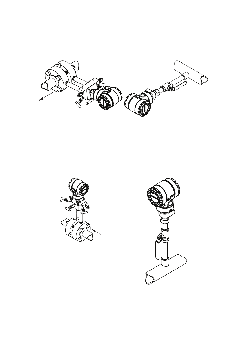
2 Mount the transmitter
2.1 Liquid applications
Procedure
1. Place taps to the side of the line.
2. Mount beside or below the taps.
3. Mount the transmitter so the drain/vent valves are oriented upward.
2.2 Gas applications
Procedure
1. Place taps in the top or side of the line.
2. Mount beside or above the taps.
6 Emerson.com/Rosemount
Page 7
March 2020 Quick Start Guide
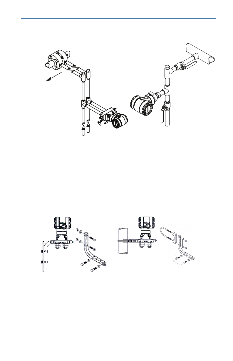
2.3 Steam applications
Procedure
1. Place taps to the side of the line.
2. Mount beside or below the taps.
3. Fill impulse lines with water.
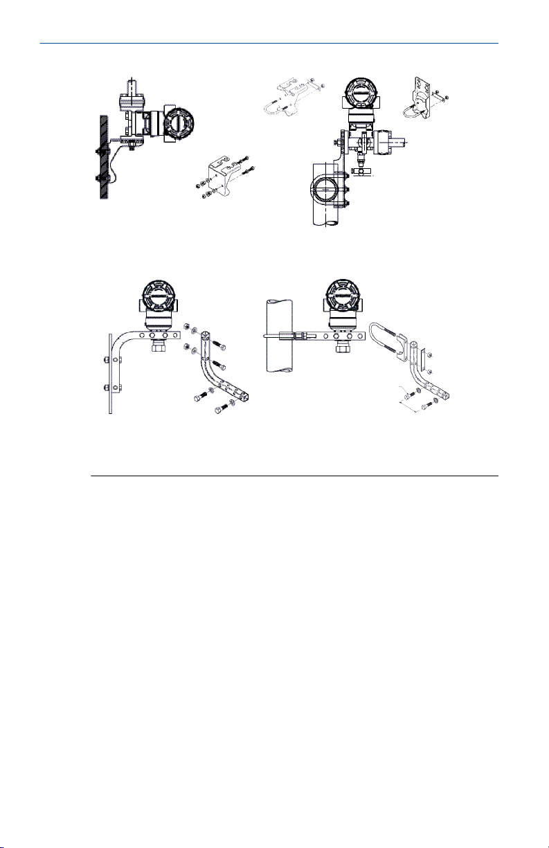
Figure 2-1: Panel and Pipe Mounting
Panel mount
Coplanar flange
Traditional flange
Quick Start Guide 7
(1)
Pipe mount
Page 8
Quick Start Guide March 2020
Rosemount 2051T
2.4
(1) × 1 panel bolts are customer supplied.
Bolting considerations
If the transmitter installation requires assembly of the process flanges,
manifolds, or flange adapters, follow the assembly guidelines to ensure a
tight seal for optimal performance characteristics of the transmitters. Use
only bolts supplied with the transmitter or sold by Emerson as spare parts.
Figure 2-2 illustrates common transmitter assemblies with the bolt length
required for proper transmitter assembly.
8 Emerson.com/Rosemount
Page 9
A
4 × 1.75-in.
(44 mm)
D
4 × 1.75-in.
(44 mm)
4 × 2.25-in.
(57 mm)
C
4 × 1.75-in.
(44 mm)
4
× 1.50-in.
(38 mm)
B
4 × 2.88-in.
(73 mm)
March 2020 Quick Start Guide
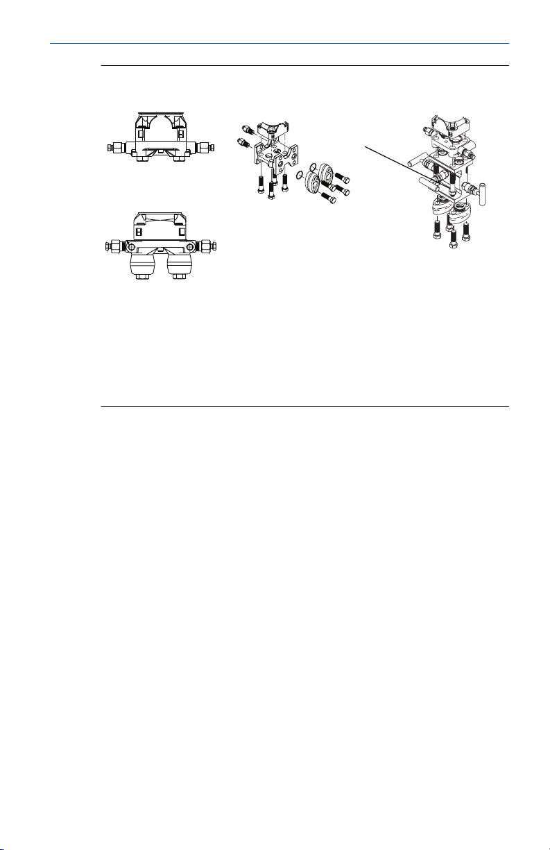
Figure 2-2: Common Transmitter Assemblies
A. Transmitter with coplanar flange
B. Transmitter with coplanar flange and optional flange adapters
C. Transmitter with traditional flange and optional flange adapters
D. Transmitter with coplanar flange and optional manifold and flange
adapters
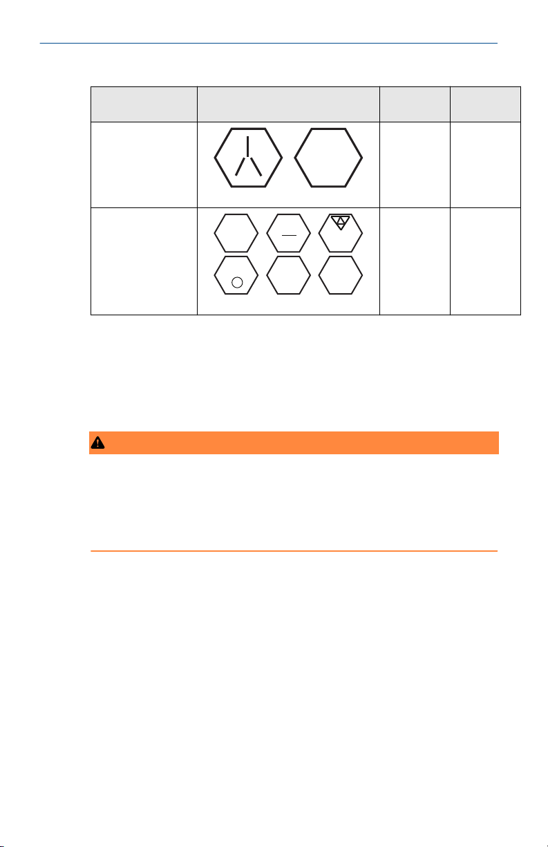
Bolts are typically carbon steel (CS) or stainless steel (SST). Confirm the
material by viewing the markings on the head of the bolt and referencing
Table 2-1. If bolt material is not shown in Table 2-1, contact a local Emerson
representative for more information.
Carbon steel bolts do not require lubrication and the stainless steel bolts are
coated with a lubricant to ease installation. However, no additional lubricant
should be applied when installing either type of bolt.
Use the following bolt installation procedure:
Procedure
1. Tighten the bolts by hand.
2. Torque the bolts to the initial torque value using a crossing pattern.
See Table 2-1 for initial torque value.
3. Torque the bolts to the final torque value using the same crossing
pattern. See Table 2-1 for final torque value.
4. Verify the flange bolts are protruding through the sensor module
Quick Start Guide 9
bolt holes before applying pressure.
Page 10
B7M
316
316
316
SW
316
STM
316
R
B8M
Quick Start Guide March 2020
Table 2-1: Torque Values for the Flange and Flange Adapter Bolts
Bolt material Head markings Initial
CS
SST
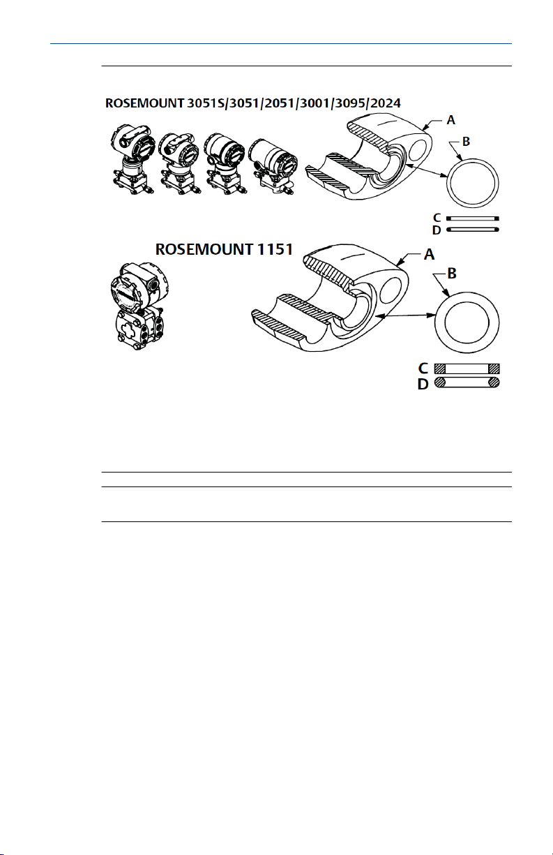
2.5 O-rings
The two styles of Rosemount flange adapters (Rosemount 1151 and
Rosemount 3051/2051/2024/3095) each require a unique O-ring (see
Figure 2-3). Use only the O-ring designed for the corresponding flange
adapter.
WARNING
Failure to install proper flange adapter O-rings may cause process leaks,
which can result in death or serious injury. The two flange adapters are
distinguished by unique O-ring grooves. Only use the O-ring that is designed
for its specific flange adapter, as shown below. When compressed, PTFE Orings tend to cold flow, which aids in their sealing capabilities.
torque
Final torque
300 in-lb 650 in-lb
150 in-lb 300 in-lb
10 Emerson.com/Rosemount
Page 11
March 2020 Quick Start Guide
Figure 2-3: O-rings
A. Flange adapter
B. O-ring
C. PFTE based
D. Elastomer
Note
You should replace PTFE O-rings if you remove the flange adapter.
2.6
2.7
Quick Start Guide 11
Environmental seal for housing
Thread sealing (PTFE) tape or paste on male threads of conduit is required to
provide a water/dust tight conduit seal and meets requirements of NEMA
Type 4X, IP66, and IP68. Consult factory if other Ingress Protection ratings
are required.
For M20 threads, install conduit plugs to full thread engagement or until
mechanical resistance is met.
®
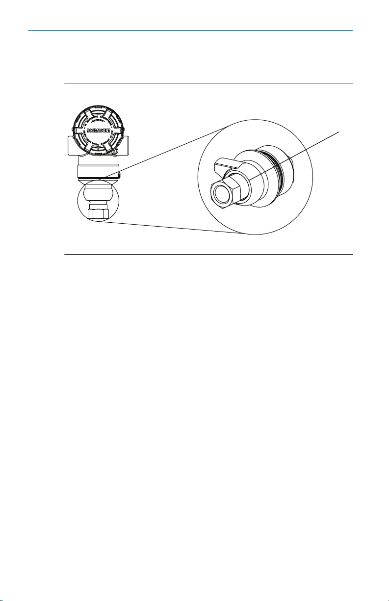
In-line gage transmitter orientation
The low side pressure port (atmospheric reference) on the in-line gage
transmitter is located in the neck of the transmitter, behind the housing. The
vent path is 360° around the transmitter between the housing and sensor.
(See Figure 2-4.)
Page 12
A
Quick Start Guide March 2020
Keep the vent path free of any obstruction, including but not limited to
paint, dust, and lubrication by mounting the transmitter so fluids can drain
away.
Figure 2-4: In-line Gage Low Side Pressure Port
A. Pressure port location
12 Emerson.com/Rosemount
Page 13

A
March 2020 Quick Start Guide
3 Housing rotation
To improve field access to wiring or to better view the optional LCD display
follow the Procedure steps.
Figure 3-1: Housing Rotation
A. Housing rotation set screw (5/64 in.)
Procedure
1. Loosen the housing rotation set screw using a 5/64 -in. hex wrench.
2. Rotate the housing clockwise to the desired location.
3. If the desired location cannot be achieved due to thread limit, rotate
the housing counterclockwise to the desired location (up to 360°
from thread limit).
4. Retighten the housing rotation set screw to no more than 7 in-lbs
when desired location is reached.
Quick Start Guide 13
Page 14
B
A
Quick Start Guide March 2020
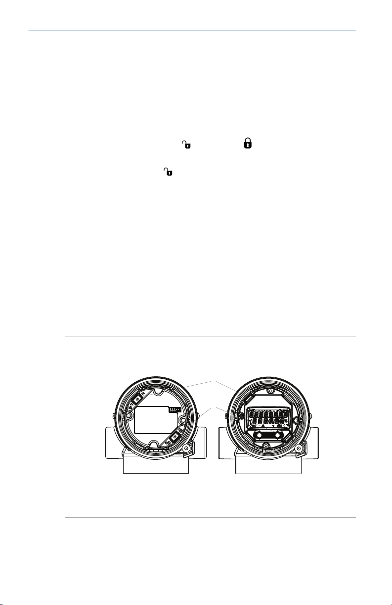
4 Set the switches
Set alarm and security switch configuration before installation as shown in
Figure 4-1.
• The alarm switch sets the analog output alarm to high or low.
• Default alarm is high.
• The security switch allows (
) or prevents ( ) any configuration of the
transmitter.
• Default security is off ( ).
Use the following procedure to change the switch configuration:
Procedure
1. If the transmitter is installed, secure the loop, and remove power.
2. Remove the housing cover opposite the field terminal side. Do not
remove the instrument cover in explosive atmospheres when the
circuit is live.
3. Slide the security and alarm switches into the preferred position
using a small screwdriver.
4. Reattach the transmitter cover. The cover must be fully engaged to
comply with explosion-proof requirements.
Example
Figure 4-1: Transmitter Electronics Board
Without LCD display meter
With LOI/LCD display
A. Alarm
B. Security
14 Emerson.com/Rosemount
Page 15

March 2020 Quick Start Guide
5 Connect the wiring and power up
Figure 5-1: Transmitter Wiring Diagrams (4–20 mA)
Aluminum
Polished 316 SST
A. 24 Vdc supply
B. RL ≥ 250
C. Current meter (optional)
Shielded twisted pair cable should be used for best results. Use 24 AWG or
larger wire that does not exceed 5,000 ft. (1500 m) in length. If applicable,
install wiring with a drip loop. Arrange the drip loop so the bottom is lower
than the conduit connections and the transmitter housing.
Quick Start Guide 15
Page 16

Quick Start Guide March 2020
CAUTION
• Installation of the transient protection terminal block does not provide
transient protection unless the Rosemount 2051HT case is properly
grounded.
• Do not run signal wiring in conduit or open trays with power wiring, or
near heavy electrical equipment.
• Do not connect the powered signal wiring to the test terminals. Power
could damage the test diode in the terminal block.
Use the following steps to wire the transmitter:
Procedure
1. Remove the housing cover on the FIELD TERMINALS side.
2. Connect the positive lead to the “+” terminal (PWR/COMM) and the
negative lead to the “–” terminal.
3. Ensure full contact with Terminal Block screw and washer. When
using a direct wiring method, wrap wire clockwise to ensure it is in
place when tightening the terminal block screw.
Note
The use of a pin or a ferrule wire terminal is not recommended as the
connection may be more susceptible to loosening over time or under
vibration
4. Ground housing to fulfill local grounding regulations.
5. Ensure proper grounding. It is important the instrument cable shield
be:
• Trimmed close and insulated from touching the transmitter
housing
• Connected to the next shield if cable is routed through a junction
box
• Connected to a good earth ground at the power supply end
6. If transient protection is needed, refer to section “Grounding for
transient terminal block” for grounding instructions.
7. Plug and seal unused conduit connections.
8. Reattach the transmitter covers. It is recommended that the cover be
tightened until there is no gap between the cover and the housing.
The covers must only be capable of being released or removed with
the aid of a tool to comply with applicable ordinary locations
requirements.
16 Emerson.com/Rosemount
Page 17

DP
A
B
D
E
C
DP
A
B
D
E
C
March 2020 Quick Start Guide
Figure 5-2: Wiring
Aluminum Polished 316 SST
A. Minimize distance
B. Trim shield and insulate
C. Protective grounding terminal
D. Insulate shield
E. Connect shield back to the power supply ground
5.1 Grounding for transient terminal block
Ground termination is provided on the outside of the electronics housing
and inside the terminal compartment. These grounds are used when the
transient protection terminal blocks are installed. It is recommended that 18
AWG or larger wire is used to connect housing ground to earth ground
(internal or external).
If the transmitter is currently not wired for power up and communication,
follow Connect the wiring and power up step Step 1 through Step 8. When
the transmitter is properly wired, refer to Figure 5-2 for internal and external
transient grounding locations.
Note
The Rosemount 2051HT polished 316 SST housing only provides ground
termination inside the terminal compartment.
Quick Start Guide 17
Page 18

Quick Start Guide March 2020
6 Verify configuration
Verify the configuration using any HART-capable configuration tool or Local
Operator Interface (LOI) - option code M4. Configuration instructions for a
Field Communicator and LOI are included in this step.
6.1 Verifying configuration with a Field Communicator
A Rosemount 2051 DD must be installed on the Field Communicator to
verify configuration. Fast Key sequences for the latest DD are shown in Table
6-1. For Fast Key sequences using legacy DD's, contact your local Emerson
representative.
Note
Emerson recommends installing the latest DD to access the complete
functionality. Visit Emerson.com/Field-Communicator for information on
updating the DD Library.
Procedure
1. Verify device configuration using the Fast Key sequences in Table
6-1.
2. A check (✓) indicates the basic configuration parameters. At
minimum, these parameters should be verified as part of
configuration and startup.
Table 6-1: Device Revision 9 and 10 (HART 7), DD Revision 1 Fast
Key Sequence
Function HART 7 HART 5
✓ Alarm and Saturation Levels 2, 2, 2, 5, 7 2, 2, 2, 5, 7
✓ Damping 2, 2, 1, 1, 5 2, 2, 1, 1, 5
✓ Range Values 2, 2, 2 2, 2, 2
✓ Tag 2, 2, 7, 1, 1 2, 2, 7, 1, 1
✓ Transfer Function 2, 2, 1, 1, 6 2, 2, 1, 1, 6
✓ Units 2, 2, 1, 1, 4 2, 2, 1, 1, 4
Burst Mode 2, 2, 5, 3 2, 2, 5, 3
Custom Display Configuration 2, 2, 4 2, 2, 4
Date 2, 2, 7, 1, 4 2, 2, 7, 1, 3
Descriptor 2, 2, 7, 1, 5 2, 2, 7, 1, 4
Digital to Analog Trim (4–20 mA
output)
18 Emerson.com/Rosemount
3, 4, 2 3, 4, 2
Page 19

March 2020 Quick Start Guide
Table 6-1: Device Revision 9 and 10 (HART 7), DD Revision 1 Fast
Key Sequence (continued)
Function HART 7 HART 5
Disable Configuration Buttons 2, 2, 6, 3 2, 2, 6, 3
Rerange with Keypad 2, 2, 2, 1 2, 2, 2, 1
Loop Test 3, 5, 1 3, 5, 1
Lower Sensor Trim 3, 4, 1, 2 3, 4, 1, 2
Message 2, 2, 7, 1, 6 2, 2, 7, 1, 5
Scaled D/A Trim (4–20 mA
output)
Sensor Temperature/Trend 3, 3, 2 3, 3, 2
Upper Sensor Trim 3, 4, 1, 1 3, 4, 1, 1
Digital Zero Trim 3, 4, 1, 3 3, 4, 1, 3
Password 2, 2, 6, 5 2, 2, 6, 4
Scaled Variable 3, 2, 2 3, 2, 2
HART Revision 5 to HART
Revision 7 switch
Long Tag
Find Device
Simulate Digital Signal
(1)
(1)
(1)
3, 4, 2 3, 4, 2
2, 2, 5, 2, 3 2, 2, 5, 2, 3
2, 2, 7, 1, 2 N/A
3, 4, 5 N/A
3, 4, 5 N/A
(1) Only available in HART Revision 7 mode.
6.2
Verifying configuration with LOI
The optional LOI can be used for commissioning the device. The LOI is a twobutton design with internal and external/rear buttons. On a polished
stainless steel housing, buttons are located internally both on the display
and terminal side of the transmitter. On an aluminum housing, buttons are
located on the display and externally underneath the top metal tag. To
activate the LOI, push any button. LOI button functionality is shown on the
bottom corners of the display. See Table 6-2 and Figure 6-2 for button
operation and menu information.
Quick Start Guide 19
Page 20

Quick Start Guide March 2020
Figure 6-1: Internal and External LOI Buttons
A. Internal buttons
B. External buttons
Table 6-2: LOI Button Operation
Button
Left No SCROLL
Right Yes ENTER
20 Emerson.com/Rosemount
Page 21

Assign PV
HART Revision
March 2020 Quick Start Guide
Figure 6-2: LOI Menu
6.3 Switch HART Revision mode
If the HART configuration tool is not capable of communicating with HART
Revision 7, the Rosemount 2051 will load a generic menu with limited
capability. The following procedures will switch the HART Revision mode
from the generic menu:
Procedure
Navigate to Manual Setup → Device Information → Identification →
Message
a) To change to HART Revision 5, Enter: HART5 in the Message field.
b) To change to HART Revision 7, Enter: HART7 in the Message field.
Note
See Table 6-1 to change HART Revision when the correct device driver is
loaded.
Quick Start Guide 21
Page 22

Quick Start Guide March 2020
7 Trim the transmitter
Devices are calibrated by the factory. Once installed, it is recommended to
perform a zero trim on gage transmitters to eliminate error due to mounting
position or static pressure effects. A zero trim can be performed using either
a Field Communicator or configuration buttons.
Note
When performing a zero trim, ensure the equalization valve is open and all
wet legs are filled to the correct level.
CAUTION
It is not recommended to zero an absolute transmitter, Rosemount
2051HTA model.
Procedure
Choose your trim procedure.
a) Analog zero trim – Sets the analog output to 4 mA.
b) Also referred to as a “rerange,” it sets the lower range value (LRV)
equal to the measured pressure.
c) The display and digital HART output remains unchanged.
d) Digital zero trim – Recalibrates the sensor zero.
e) The LRV is unaffected. The pressure value will be zero (on display and
HART output). 4 mA point may not be at zero.
f) This requires the factory calibrated zero pressure is within a range of
3% of the URV [0 ± 3% x URV].
Example
URV = 250 inH2O Applied Zero Pressure = ± 0.03 x 250 inH2O = ± 7.5 inH2O
(compared to factory settings) values outside this range will be rejected by
the transmitter
7.1
22 Emerson.com/Rosemount
Trimming with a Field Communicator
Procedure
1. Connect the Field Communicator, see Connect the wiring and power
up for instructions.
2. Follow the HART menu to perform the desired zero trim.
Page 23

March 2020 Quick Start Guide
Analog zero (set 4 mA) Digital zero
Fast Key sequence 3, 4, 2 3, 4, 1, 3
7.2 Trimming with configuration buttons
A zero trim is to be performed using one of the three possible sets of
configuration buttons located above the terminal block or under the top
tag.
To access the configuration buttons on a polished stainless steel housing,
remove the terminal side housing cover.
To access the configuration buttons on an aluminum housing, loosen the
screw on the top tag and slide the tag on the top of the transmitter.
Figure 7-1: External or Rear/Terminal-Side Configuration Buttons
(1)
LOI
Analog zero and
span
Digital zero
Aluminum
Polished 316 SST
Quick Start Guide 23
Page 24

Quick Start Guide March 2020
A. Configuration buttons
(1) LOI buttons (option M4) only offer front facing buttons on SST housing (option
1). Options D4 and DZ can still be purchased for rear/terminal-side facing
buttons.
Use one of the following procedures to perform a zero trim:
7.2.1 Perform trim with LOI (option M4)
Procedure
1. Set the transmitter pressure.
2. See Figure 6-2 for the operating menu.
a) Perform an analog zero trim by selecting Rerange.
b) Perform a digital zero trim by selecting Zero Trim.
7.2.2 Perform trim with analog zero and span (option D4)
Procedure
1. Set the transmitter pressure.
2. Press and hold the Zero button for two seconds to perform an analog
zero trim.
7.2.3 Perform trim with digital zero (option DZ)
Procedure
1. Set the transmitter pressure.
2. Press and hold the Zero button for two seconds to perform a digital
zero trim.
24 Emerson.com/Rosemount
Page 25

March 2020 Quick Start Guide
8 Safety instrumented systems
For safety certified installations, refer to the Rosemount 2051 Reference
Manual for installation procedure and system requirements.
Quick Start Guide 25
Page 26

Quick Start Guide March 2020
9 Product certifications
Rev 1.14
9.1 European Directive Information
A copy of the EC Declaration of Conformity can be found at the end of the
Quick Start Guide. The most recent revision of the EC Declaration of
Conformity can be found at EmersonProcess.com/Rosemount.
9.2 Ordinary Location Certification
As standard, the transmitter has been examined and tested to determine
that the design meets the basic electrical, mechanical, and fire protection
requirements by a nationally recognized test laboratory (NRTL) as accredited
by the Federal Occupational Safety and Health Administration (OSHA).
9.3 North America
E5 USA Explosionproof (XP) and Dust-Ignitionproof (DIP)
Certificate:
Standards:
Markings:
I5 USA Intrinsic Safety (IS) and Nonincendive (NI)
Certificate:
Standards:
Markings:
IE USA FISCO
Certificate:
Standards:
3032938
FM Class 3600 – 2011, FM Class 3615 – 2006, FM Class 3616
– 2011, FM Class 3810 – 2005, ANSI/NEMA 250 -– 2008,
ANSI/IEC 60529 2004
XP CL I, DIV 1, GP B, C, D; DIP CL II, DIV 1, GP E, F, G; CL III;
T5(–50 °C ≤ Ta ≤ +85 °C); Factory Sealed; Type 4X
3033457
FM Class 3600 – 2011, FM Class 3610 – 2010, FM Class 3611
– 2004, FM Class 3810 – 2005, ANSI/NEMA 250 – 2008
IS CL I, DIV 1, GP A, B, C, D; CL II, DIV 1, GP E, F, G; Class III; DIV
1 when connected per Rosemount drawing 02051-1009;
Class I, Zone 0; AEx ia IIC T4; NI CL 1, DIV 2, GP A, B, C, D; T4(–
50 °C ≤ Ta ≤ +70 °C); Type 4x
3033457
FM Class 3600 – 2011, FM Class 3610 – 2010, FM Class 3611
– 2004, FM Class 3810 – 2005
26 Emerson.com/Rosemount
Page 27

March 2020 Quick Start Guide
Markings:
E6 Canada Explosion-Proof, Dust Ignition Proof
Certificate:
Standards:
Markings:
I6 Canada Intrinsic Safety
Certificate:
Standards:
Markings:
IS CL I, DIV 1, GP A, B, C, D when connected per Rosemount
drawing 02051-1009 (–50 °C ≤ Ta ≤ +60 °C); Type 4x
2041384
CAN/CSA C22.2 No. 0-10, CSA Std C22.2 No. 25-1966, CSA
Std C22.2 No. 30-M1986, CAN/CSA-C22.2 No. 94-M91, CSA
Std C22.2 No.142-M1987, CAN/CSA-C22.2 No.157-92, CSA
Std C22.2 No. 213-M1987, CAN/CSA-E60079-0:07, CAN/CSAE60079-1:07, CAN/CSA-E60079-11-02, CAN/CSA-C22.2 No.
60529:05, ANSI/ISA-12.27.01–2003
Explosion-Proof for Class I, Divisions 1, Groups B, C, and D.
Dust-Ignition Proof for Class II and Class III, Division 1, Groups
E, F, and G. Suitable for Class I, Division 2; Groups A, B, C, and
D for indoor and outdoor hazardous locations. Class I Zone 1
Ex d IIC T5. Enclosure type 4X, factory sealed. Single Seal
2041384
CSA Std. C22.2 No. 142 - M1987, CSA Std. C22.2 No. 213 M1987, CSA Std. C22.2 No. 157 - 92, CSA Std. C22.2 No. 213
- M1987, ANSI/ISA 12.27.01 – 2003, CAN/CSA-E60079-0:07,
CAN/CSA-E60079-11:02
Intrinsically safe for Class I, Division 1, Groups A, B, C, and D
when connected in accordance with Rosemount drawing
02051-1008. Ex ia IIC T3C. Single Seal. Enclosure Type 4X
9.4 Europe
E1 ATEX Flameproof
Certificate:
Standards:
Markings:
Special Conditions for Safe Use (X):
1. The Ex d blanking elements, cable glands and wiring needs to be
2. This device contains a thin wall diaphragm. Installation, maintenance
Quick Start Guide 27
KEMA 08ATEX0090X
EN60079-0:2006, EN60079-1:2007, EN60079-26:2007
II 1/2 G Ex d IIC T6 IP66 (–50 °C ≤ Ta ≤ 65 °C); II 1/2 G Ex d
IIC T5 IP66 (–50 °C ≤Ta ≤ 80 °C)
suitable for a temperature of 90 °C.
and use shall take into account the environmental conditions to
Page 28

Quick Start Guide March 2020
which the diaphragm will be subjected. The manufacturer’s
instructions for maintenance shall be followed in detail to assure
safety during its expected lifetime.
3. In case of repair, contact the manufacturer for information on the
dimensions of the flameproof joints.
I1 ATEX Intrinsic Safety
Certificate:
Standards:
Markings:
Baseefa08ATEX0129X
EN60079-0:2012, EN60079-11:2012
II 1 G Ex ia IIC T4 Ga (–60 °C ≤ Ta ≤ +70 °C)
Table 9-1: Input Parameters
Parameter HART Fieldbus/
Voltage U
Current I
Power P
i
Capacitance Ci0.012 μF 0 μF
Inductance Li0 mH 0 mH
30 V 30 V
i
200 mA 300 mA
i
1 W 1.3 W
PROFIBUS
®
Special Conditions for Safe Use (X):
1. If the equipment is fitted with an optional 90 V transient suppressor,
it is incapable of withstanding the 500 V isolation from earth test and
this must be taken into account during installation.
2. The enclosure may be made of aluminum alloy and given a protective
polyurethane paint finish; however care should be taken to protect it
from impact and abrasion when located in Zone 0.
IA ATEX FISCO
Certificate:
Standards:
Markings:
Baseefa08ATEX0129X
EN60079-0:2012, EN60079-11:2012
II 1 G Ex ia IIC T4 Ga (–60 °C ≤ Ta ≤ +60 °C)
Table 9-2: Input Parameters
Parameter FISCO
Voltage U
Current I
28 Emerson.com/Rosemount
17.5 V
i
380 mA
i
Page 29

March 2020 Quick Start Guide
Table 9-2: Input
Parameters (continued)
Parameter FISCO
Power P
i
Capacitance Ci0 μF
Inductance Li0 mH
5.32 W
Special Conditions for Safe Use (X):
1. If the equipment is fitted with an optional 90 V transient suppressor,
it is incapable of withstanding the 500 V isolation from earth test and
this must be taken into account during installation.
2. The enclosure may be made of aluminum alloy and given a protective
polyurethane paint finish; however care should be taken to protect it
from impact and abrasion when located in Zone 0.
N1 ATEX Type n
Certificate:
Standards:
Markings:
Baseefa08ATEX0130X
EN60079-0:2012, EN60079-15:2010
II 3G Ex nA IIC T4 Gc (–40 °C ≤ Ta ≤ +70 °C)
Special Conditions for Safe Use (X):
1. If the equipment is fitted with an optional 90 V transient suppressor,
it is incapable of withstanding the 500 V electrical strength test as
defined in clause 6.5.1 of by EN 60079-15:2010. This must be taken
into account during installation.
ND ATEX Dust
Certificate:
Standards:
Markings:
Baseefa08ATEX0182X
EN60079-0:2012, EN60079-31:2009
II 1 D Ex ta IIIC T95 °C T
105 °C Da (–20 °C ≤ Ta ≤ +85 °C)
500
Special Conditions for Safe Use (X):
1. If the equipment is fitted with an optional 90 V transient suppressor,
it is incapable of withstanding the 500 V isolation from earth test and
this must be taken into account during installation.
Quick Start Guide 29
Page 30

Quick Start Guide March 2020
9.5 International
E7 IECEx Flameproof
Certificate:
Standards:
Markings:
IECExKEM08.0024X
IEC60079-0:2004, IEC60079-1:2007-04, IEC60079-26:2006
Ex d IIC T6/T5 IP66, T6(–50 °C ≤ Ta ≤ +65 °C), T5(–50 °C ≤ Ta ≤
+80 °C)
Table 9-3: Process Temperature
Temperature class Process temperature
T6 –50°C to +65 °C
T5 –50 °C to +80 °C
Special Conditions for Safe Use (X):
1. The device contains a thin wall diaphragm. Installation, maintenance
and use shall take into account the environmental conditions to
which the diaphragm will be subjected. The manufacturer’s
instructions for maintenance shall be followed in detail to assure
safety during its expected lifetime.
2. The Ex d blanking elements, cable glands, and wiring shall be suitable
for a temperature of 90 °C.
3. In case of repair, contact the manufacturer for information on the
dimensions of the flameproof joints.
I7 IECEx Intrinsic Safety
Certificate:
Standards:
Markings:
IECExBAS08.0045X
IEC60079-0:2011, IEC60079-11:2011
Ex ia IIC T4 Ga (–60 °C ≤ Ta ≤ +70 °C)
Table 9-4: Input Parameters
Parameter HART Fieldbus/PROFIBUS
Voltage U
Current I
Power P
i
Capacitance Ci0.012 μF 0 μF
Inductance Li0 mH 0 mH
30 Emerson.com/Rosemount
30 V 30 V
i
200 mA 300 mA
i
1 W 1.3 W
Page 31

March 2020 Quick Start Guide
Special Conditions for Safe Use (X):
1. If the equipment is fitted with an optional 90 V transient suppressor,
it is incapable of withstanding the 500 V isolation from earth test and
this must be taken into account during installation.
2. The enclosure may be made of aluminum alloy and given a protective
polyurethane paint finish; however care should be taken to protect it
from impact and abrasion when located in Zone 0.
IG IECEx FISCO
Certificate:
Standards:
Markings:
IECExBAS08.0045X
IEC60079-0:2011, IEC60079-11:2011
Ex ia IIC T4 Ga (–60 °C ≤Ta ≤ +60 °C)
Table 9-5: Input Parameters
Parameter FISCO
Voltage U
Current I
Power P
i
Capacitance Ci0 μF
Inductance Li0 mH
17.5 V
i
380 mA
i
5.32 W
Special Conditions for Safe Use (X):
1. If the equipment is fitted with an optional 90 V transient suppressor,
it is incapable of withstanding the 500 V isolation from earth test and
this must be taken into account during installation.
2. The enclosure may be made of aluminum alloy and given a protective
polyurethane paint finish; however care should be taken to protect it
from impact and abrasion when located in Zone 0.
N7 IECEx Type n
Certificate:
Standards:
Markings:
IECExBAS08.0046X
IEC60079-0:2011, IEC60079-15:2010
Ex nA IIC T4 Gc (–40 °C ≤Ta ≤ +70 °C)
Special Conditions for Safe Use (X):
1. If fitted with a 90 V transient suppressor, the equipment is not
capable of withstanding the 500 V electrical strength test as defined
Quick Start Guide 31
Page 32

Quick Start Guide March 2020
in clause 6.5.1 of IEC60079-15:2010. This must be taken into
account during installation.
9.6 Brazil
E2 INMETRO Flameproof
Certificate:
Standards:
UL-BR 14.0375X
ABNT NBR IEC60079-0:2008 + Errata 1:2011, ABNT NBR IEC
60079-1:2009 + Errata 1:2011, ABNT NBR IEC 60079-26:2008
+ Errata 1:2009
Markings:
Ex d IIC T6/T5 Gb IP66, T6(–50 °C ≤Ta ≤ +65 °C), T5(–50 °C ≤T
≤ +80 °C)
Special Conditions for Safe Use (X):
1. The device contains a thin wall diaphragm. Installation, maintenance
and use shall take into account the environmental conditions to
which the diaphragm will be subjected. The manufacturer’s
instructions for installation and maintenance shall be followed in
detail to assure safety during its expected lifetime.
2. The Ex d blanking elements, cable glands, and wiring shall be suitable
for a temperature of 90 °C.
3. In case of repair, contact the manufacturer for information on the
dimensions of the flameproof joints.
I2 INMETRO Intrinsic Safety
Certificate:
Standards:
UL-BR 14.0759X
ABNT NBR IEC 60079-0:2008 + Errata 1:2011; ABNT NBR IEC
60079-11:2009
Markings:
Ex ia IIC T4 Ga (–60 °C ≤Ta ≤ +70 °C)
a
Table 9-6: Input Parameters
Parameter HART Fieldbus/PROFIBUS
Voltage U
Current I
Power P
i
Capacitance Ci12 nF 0
Inductance Li0 0
32 Emerson.com/Rosemount
30 V 30 V
i
200 mA 300 mA
i
1 W 1.3 W
Page 33

March 2020 Quick Start Guide
Special Conditions for Safe Use (X):
1. If the equipment is fitted with an optional 90 V transient suppressor,
it is incapable of withstanding the 500 V insulation from earth test
and this must be taken into account during installation.
2. The enclosure may be made of aluminium alloy and given a
protective polyurethane paint finish; however care should be taken
to protect it from impact and abrasion when located in atmospheres
that require ELP Ga.
IB INMETRO FISCO
Certificate:
Standards:
UL-BR 14.0759X
ABNT NBR IEC 60079-0:2008 + Errata 1:2011; ABNT NBR IEC
60079-11:2009
Markings:
Ex ia IIC T4 Ga (–60 °C ≤Ta ≤ +60 °C)
Table 9-7: Input Parameters
Parameter FISCO
Voltage U
Current I
Power P
i
Capacitance Ci0 nF
Inductance Li0 μH
17.5 V
i
380 mA
i
5.32 W
Special Conditions for Safe Use (X):
1. If the equipment is fitted with an optional 90 V transient suppressor,
it is incapable of withstanding the 500 V insulation from earth test
and this must be taken into account during installation.
2. The enclosure may be made of aluminium alloy and given a
protective polyurethane paint finish; however care should be taken
to protect it from impact and abrasion when located in atmospheres
that require ELP Ga.
9.7
China
E3 China Flameproof
Certificate:
Standards:
Quick Start Guide 33
GYJ13.1386X; GYJ15.1366X [Flowmeters]
GB3836.1-2010, GB3836.2-2010, GB3836.20-2010-2010
Page 34

Quick Start Guide March 2020
Markings:
Pressure Transmitter: Ex d IIC Gb, T6(–50 °C ≤ Ta ≤ +65 °C),
T5(–50 °C ≤ Ta ≤ +80 °C)
Flowmeter: Ex d IIC Ga/Gb, T6(–50 °C ≤ Ta ≤ +65 °C), T5(–50
°C ≤ Ta ≤ +80 °C)
Special Conditions for Safe Use (X):
1. Symbol “X” is used to denote specific conditions of use:
2. The Ex d blanking elements, cable glands, and wiring shall be suitable
for a temperature of 90 °C.
3. This device contains a thin wall diaphragm. Installation, maintenance
and use shall take into account the environment conditions to which
the diaphragm will be subjected.
4. The relation between T code and ambient temperature range is:
T
a
–50 °C ≤ Ta ≤ +80 °C T5
–50 °C ≤ Ta ≤ +65 °C T6
Temperature class
5. The earth connection facility in the enclosure should be connected
reliably.
6. During installation, use and maintenance of the product, observe the
warning “Don’t open the cover when the circuit is alive.”
7. During installation, there should be no mixture harmful to
flameproof housing
8. Cable entry and conduit, certified by NEPSI with type of protection Ex
d IIC Gb and appropriate thread form, should be applied when
installed in a hazardous location. Blanking elements should be used
on the redundant cable entries.
9. End users are not permitted to change any internal components, but
to settle the problem in conjunction with the manufacturer to avoid
damage to the product.
10. Maintenance should be done in a non-hazardous location.
11. During installation, use and maintenance of this product, observe the
following standards: GB3836.13-2013, GB3836.15-2000,
GB3836.16-2006, GB50257-2014
I3 China Intrinsic Safety
Certificate:
34 Emerson.com/Rosemount
GYJ12.1295X; GYJ15.1365X [Flowmeters]
Page 35

March 2020 Quick Start Guide
Standards:
Markings:
GB3836.1-2010, GB3836.4-2010, GB3836.20-2010
Ex ia IIC T4 Ga (–60 °C ≤ Ta ≤ +70 °C)
Special Conditions for Safe Use (X):
1. Symbol “X” is used to denote specific conditions of use:
2. If the apparatus is fitted with an optional 90 V transient suppressor, it
is not capable of withstanding the 500 V insulation test for 1 minute.
This must be taken into account when installing the apparatus.
3. The enclosure may be made of aluminum alloy and given a protective
polyurethane paint finish; however, care should be taken to protect it
from impact or abrasion if located in Zone 0.
4. The relation between T code and ambient temperature range is:
Model T code Temperature range
HART, Fieldbus, PROFIBUS, and Low Power T4 –60 °C ≤ Ta ≤ +70 °C
5. Intrinsically Safe parameters:
Parameter HART Fieldbus/PROFIBUS
Voltage U
Current I
Power P
i
Capacitance Ci0.012 μF 0 μF
Inductance Li0 mH 0 mH
30 V 30 V
i
200 mA 300 mA
i
1 W 1.3 W
Note
FISCO parameters comply with the requirements for FISCO field
devices in GB3836.19-2010 [For Flowmeters] When Rosemount 644
Temperature Transmitter is used, the transmitter should be used
with Ex-certified associated apparatus to establish explosion
protection system that can be used in explosive gas atmospheres.
Wiring and terminals should comply with the instruction manual of
both Rosemount 644 and associated apparatus. The cables between
Rosemount 644 and associated apparatus should be shielded cables
(the cables must have insulated shield). The shielded cable has to be
grounded reliably in a non-hazardous area.
6. The product should be used with Ex-certified associated apparatus to
establish explosion protection system that can be used in explosive
Quick Start Guide 35
Page 36

Quick Start Guide March 2020
gas atmospheres. Wiring and terminals should comply with the
instruction manual of the product and associated apparatus.
7. The cables between this product and associated apparatus should be
shielded cables (the cables must have insulated shield). The shielded
cable has to be grounded reliably in a non-hazardous area.
8. End users are not permitted to change any internal components, and
needs to settle the problem in conjunction with the manufacturer to
avoid damage to the product.
9. During installation, use and maintenance of this product, observe the
following standards: GB3836.13-2013, GB3836.15-2000,
GB3836.16-2006, GB3836.18-2010, GB50257-2014.
9.8 Japan
E4 Japan Flameproof
Certificate:
Markings:
TC20598, TC20599, TC20602, TC20603 [HART]; TC20600,
TC20601, TC20604, TC20605 [Fieldbus]
Ex d IIC T5
9.9 Technical Regulations Customs Union (EAC)
EM EAC Flameproof
Certificate:
Markings:
Special Conditions for Safe Use (X):
1. See certificate for special conditions.
IM EAC Intrinsically Safe
Certificate:
Markings:
Special Conditions for Safe Use (X):
1. See certificate for special conditions.
RU C-US.GB05.B.01199
Ga/Gb Ex d IIC X, T5(–50 °C ≤ Ta ≤ +80 °C), T6(–50 °C ≤ Ta ≤
+65 °C)
RU C-US.GB05.B.01199
0Ex ia IIC T4 Ga X (–60 °C ≤ Ta ≤ +70 °C)
36 Emerson.com/Rosemount
Page 37

March 2020 Quick Start Guide
9.10 Combinations
K1 Combination of E1, I1, N1, and ND
K2 Combination of E2 and I2
K5 Combination of E5 and I5
K6 Combination of E6 and I6
K7 Combination of E7, I7, N7, and IECEx Dust
IECEx Dust
9.11
Certificate:
Standards:
Markings:
Special Condition for Safe Use (X):
1. If the equipment is fitted with an optional 90 V transient suppressor,
it is incapable of withstanding a 500 V isolation from earth test and
this must be taken into account during installation.
KA Combination of E1, I1, and K6
KB Combination of K5 and K6
KC Combination of E1, I1, and K5
KD Combination of K1, K5, and K6
KM Combination of EM and IM
IECEx BAS 08.0058X
IEC60079-0:2011, IEC60079-31:2008
Ex ta IIIC T95 °C T
105 °C Da (–20 °C ≤ Ta ≤ +85 °C)
500
Additional Certifications
SBS American Bureau of Shipping (ABS) Type Approval
Certificate:
Intended Use:
ABS Rules:
09-HS446883B-3-PDA
Marine and Offshore Applications – Measurement of either
Gauge or Absolute Pressure for Liquid, Gas, and Vapor.
2013 Steel Vessels Rules 1-1-4/7.7, 1-1-Appendix 3,
4-8-3/1.7, 4-8-3/13.1
SBV Bureau Veritas (BV) Type Approval
Certificate:
BV Rules:
Quick Start Guide 37
23157/B0 BV
Bureau Veritas Rules for the Classification of Steel Ships
Page 38

Quick Start Guide March 2020
Application:
Class notations: AUT-UMS, AUT-CCS, AUT-PORT and AUTIMS; Pressure transmitter type 2051 cannot be installed on
diesel engines
SDN Det Norske Veritas (DNV) Type Approval
Certificate:
Intended Use:
Application:
TAA000004F
DNV GL Rules for Classification - Ships and offshore units
Location classes
Type 2051
Temperature D
Humidity B
Vibration A
EMC B
Enclosure D
SLL Lloyds Register (LR) Type Approval
Certificate:
Application:
11/60002
Environmental categories ENV1, ENV2, ENV3 and ENV5
38 Emerson.com/Rosemount
Page 39

March 2020 Quick Start Guide
Figure 9-1: Rosemount 2051 Declaration of Conformity
Quick Start Guide 39
Page 40

Quick Start Guide March 2020
40 Emerson.com/Rosemount
Page 41

March 2020 Quick Start Guide
Quick Start Guide 41
Page 42

Quick Start Guide March 2020
9.12 China RoHS
42 Emerson.com/Rosemount
Page 43

March 2020 Quick Start Guide
Quick Start Guide 43
Page 44

*00825-0100-4107*
00825-0100-4107, Rev. EA
Quick Start Guide
March 2020
Global Headquarters
Emerson Automation Solutions
6021 Innovation Blvd.
Shakopee, MN 55379, USA
+1 800 999 9307 or +1 952 906 8888
+1 952 204 8889
RFQ.RMD-RCC@Emerson.com
Latin America Regional Office
Emerson Automation Solutions
1300 Concord Terrace, Suite 400
Sunrise, FL 33323, USA
+1 954 846 5030
+1 954 846 5121
RFQ.RMD-RCC@Emerson.com
Asia Pacific Regional Office
Emerson Automation Solutions
1 Pandan Crescent
Singapore 128461
+65 6777 8211
+65 6777 0947
Enquiries@AP.Emerson.com
North America Regional Office
Emerson Automation Solutions
8200 Market Blvd.
Chanhassen, MN 55317, USA
+1 800 999 9307 or +1 952 906 8888
+1 952 204 8889
RMT-NA.RCCRFQ@Emerson.com
Europe Regional Office
Emerson Automation Solutions Europe
GmbH
Neuhofstrasse 19a P.O. Box 1046
CH 6340 Baar
Switzerland
+41 (0) 41 768 6111
+41 (0) 41 768 6300
RFQ.RMD-RCC@Emerson.com
Middle East and Africa Regional Office
Emerson Automation Solutions
Emerson FZE P.O. Box 17033
Jebel Ali Free Zone - South 2
Dubai, United Arab Emirates
+971 4 8118100
+971 4 8865465
RFQ.RMTMEA@Emerson.com
Linkedin.com/company/Emerson-
Automation-Solutions
Twitter.com/Rosemount_News
Facebook.com/Rosemount
Youtube.com/user/
RosemountMeasurement
©
2020 Emerson. All rights reserved.
Emerson Terms and Conditions of Sale are
available upon request. The Emerson logo is a
trademark and service mark of Emerson Electric
Co. Rosemount is a mark of one of the Emerson
family of companies. All other marks are the
property of their respective owners.
 Loading...