

Page 1
Rosemount™ 1057
Single Channel Transmitter
Quick Start Guide
00825-0100-3157, Rev AB
April 2020
Page 2

Quick Start Guide April 2020
Safety Information
Rosemount 1057 Reference Manual
For information on specifications, programming, and calibrations see the Rosemount 1057 Reference
Manual at Emerson.com/Rosemount: Manual: Rosemount 1057 Three-Input Intelligent Transmitter.
Read this page before proceeding!
Your instrument purchase from Emerson is one of the finest available for your particular
application.These instruments have been designed and tested to meet many national and
international standards.Experience indicates that its performance is directly related to the quailty of
the installation and knowledge of the user in operating and maintaining the instrument.To ensure its
continued operation to the design specifications, personnel should read this Quick Start Guide
thoroughly before proceeding with installation, commissioning, operation, and maintenance of this
instrument.If this equipment is used in a manner not specified by the manufacturer, the protection
provided by it against hazards may be impaired.
• Failure to follow the proper instructions may cause any one of the following situations to occur:
loss of life, personal injury, property damage, damage to this instrument, and warranty
invalidation.
• Ensure that you have received the correct model and options from your purchase order. Verify
that this Quick Start Guide covers your model and options. If it does not, call 800 854 8257 or 949
757 8500 to request the correct Quick Start Guide.
• For clarification of instructions, contact your Rosemount representative.
• Follow all warnings, cautions, and instructions marked on and supplied with the product.
• Use only qualified personnel to install, operate, program, and maintain the product.
• Inform and educate your personnel in the proper installation, operation, and maintenance of the
product.
• Install equipment as specified in the installation instructions of the appropriate Reference Manual
and per applicable local and national codes. Connect all products to the proper electrical and
pressure sources.
• Use only factory documented components for repair. Tampering or unauthorized substitution of
parts and procedures can affect the performance and cause unsafe operation of your process.
• All equipment doors must be closed, and protective covers must be in place unless qualified
personnel are performing maintenance.
2 Emerson.com/Rosemount
Page 3

April 2020 Quick Start Guide
WARNING
Risk of electrical shock
Installation and servicing of this product may expose personnel to dangerous voltages.
Equipment protected throughout by double insulation.
Disconnect main power wired to separate power source before servicing.
Do not operate or energize instrument with case open.
Signal wiring within this box must be rated at least 240 V for European mains operation.
Non-metallic cable strain reliefs do not provide grounding between conduit connections. Use
grounding type bushings and jumper wires.
Unused cable conduit entries must be securely sealed by non-flammable closures to provide
exposure integrity in compliance with personal safety and environmental protection
requirements. Unused conduit openings must be sealed with Type 4X or IP66 conduit plugs to
maintain the ingress protection rating (Type 4X).
Electrical installation must be in accordance with the National Electrical Code (ANSI/NFPA-70)
and/or any other national or local codes.
Operate only with front panel fastened and in place.
Safety and performance require that this instrument be connected and properly grounded
through a three-wire power source.
Proper use and configuration is the operator's responsibility.
Contents
First steps.....................................................................................................................................5
Install......................................................................................................................................... 10
Wire........................................................................................................................................... 11
Navigating the display................................................................................................................17
Start up transmitter....................................................................................................................23
Product certifications................................................................................................................. 26
EU Declaration of Conformity.....................................................................................................28
China RoHS table........................................................................................................................30
Quick Start Guide 3
Page 4

Quick Start Guide April 2020
4 Emerson.com/Rosemount
Page 5

April 2020 Quick Start Guide
1 First steps
1.1 Unpack and inspect
Procedure
1. Inspect the shipping container. If it is damaged, contact the shipper
immediately for instructions.
2. If there is no apparent damage, unpack the container. Be sure all
items shown on the packing list are present. If items are missing,
notify Emerson immediately.
Quick Start Guide 5
Page 6
Quick Start Guide April 2020
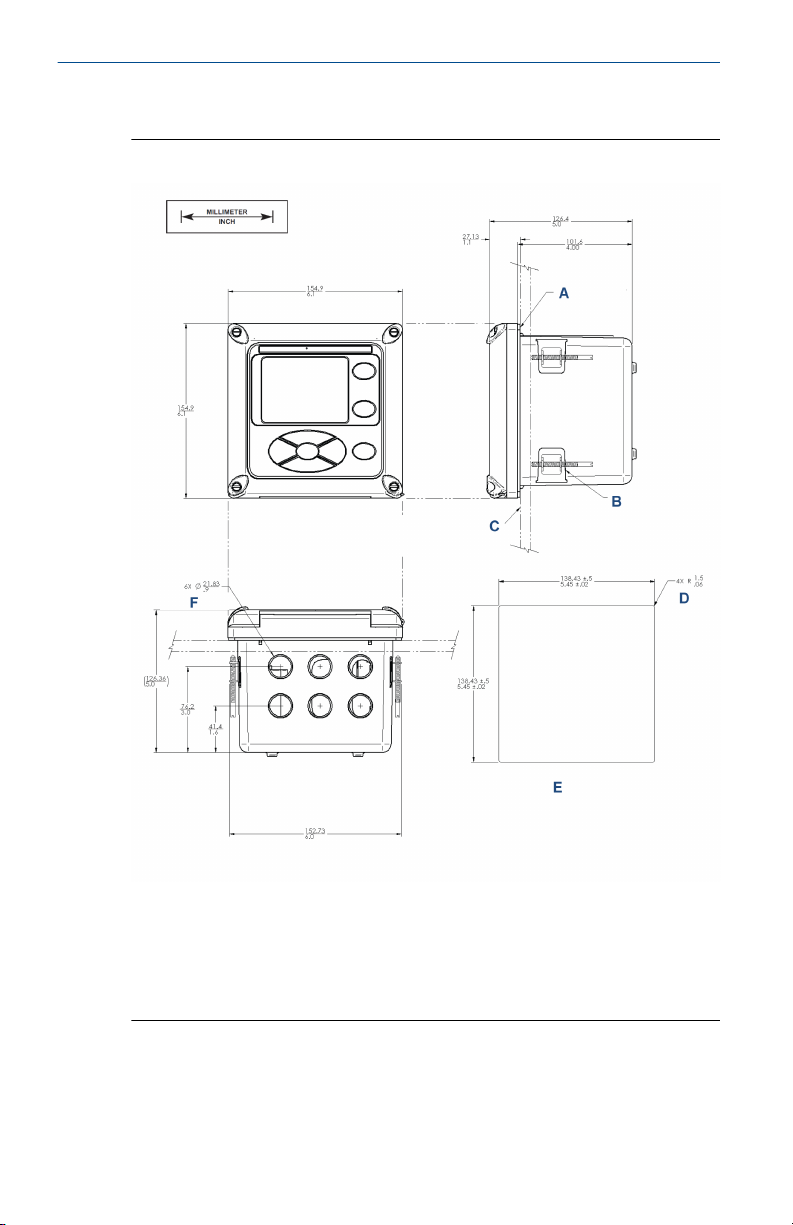
1.2 Mount
Figure 1-1: Panel Mounting Dimensions
A. Panel mount gasket
B. Four mounting brackets and screws provided with transmitter
C. Panel supplied by other. Maximum thickness: 0.375 in. (9.52 mm)
D. Maximum radius
E. Panel cut-out
6 Emerson.com/Rosemount
Page 7
April 2020 Quick Start Guide
Note
The front panel is hinged at the bottom. The panel swings down for easy
access to the wiring locations. Panel mounting seal integrity (4/4X) for
outdoor applications is the responsibility of the end user.
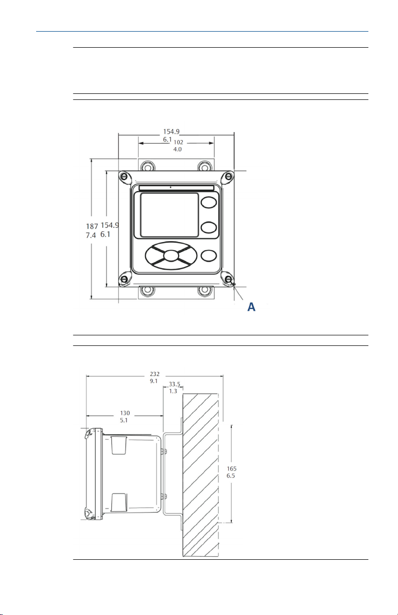
Figure 1-2: Wall Mount Front View
A. Four cover screws
Figure 1-3: Wall Mount Side View
Quick Start Guide 7
Page 8
Quick Start Guide April 2020
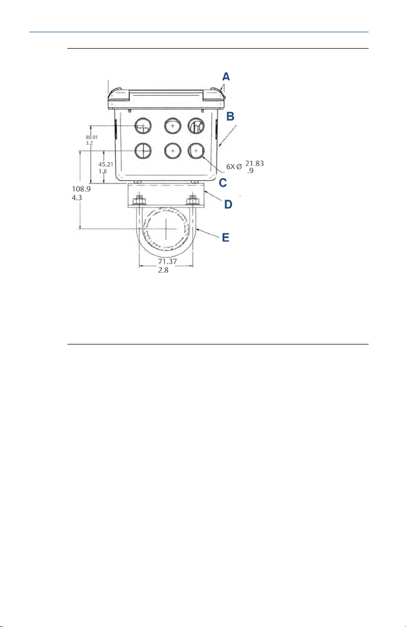
Figure 1-4: Pipe Mount Bottom View
A. Front panel
B. Panel and pipe mount enclosure
C. Conduit opening
D. 2-in. (50.8 mm) pipe mount bracket
E. Two sets U-bolts for 2-in. (50.8 mm) pipe in kit PN 23820-00
8 Emerson.com/Rosemount
Page 9
April 2020 Quick Start Guide
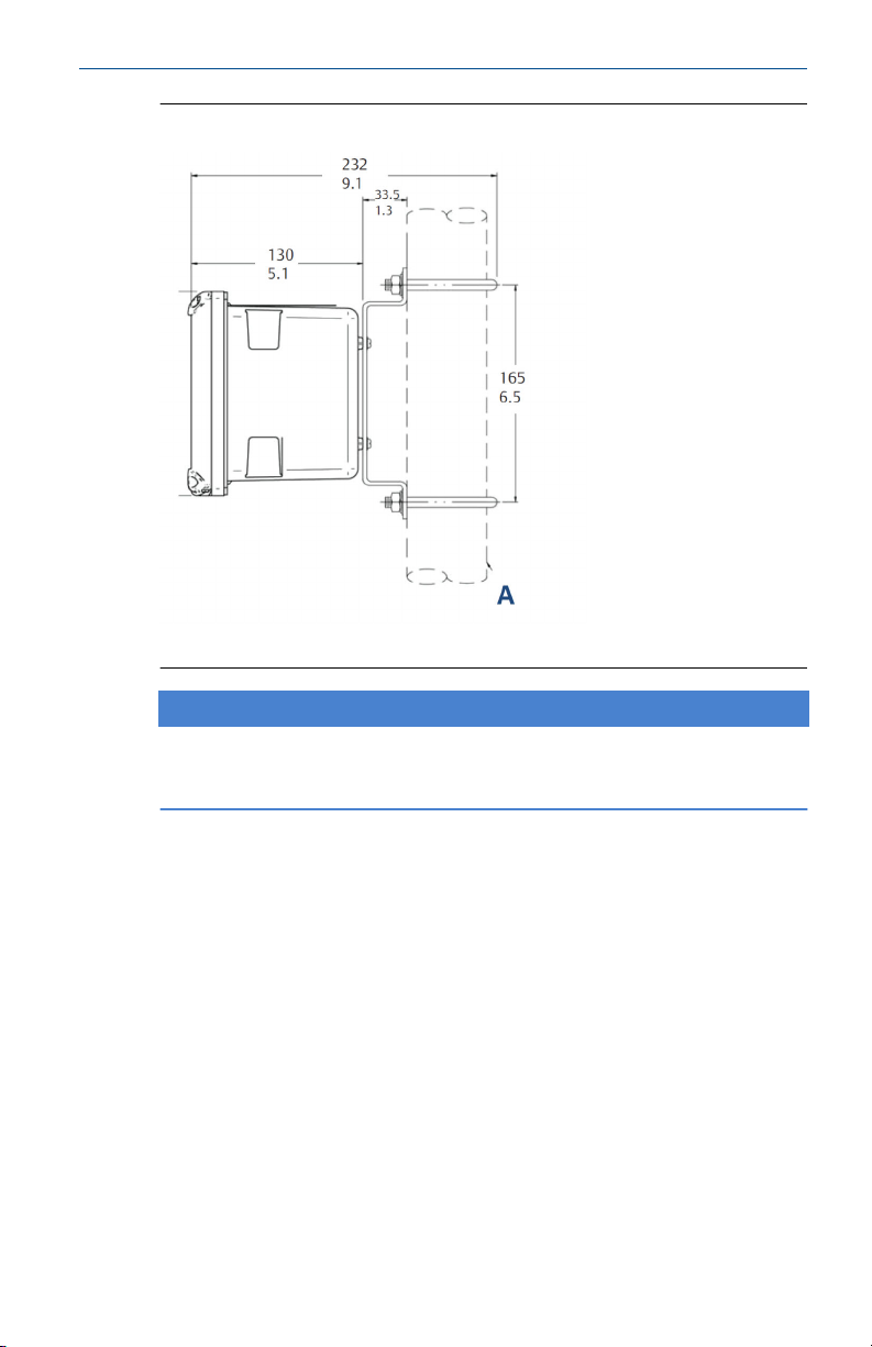
Figure 1-5: Pipe Mount Side View
A. 2-in. (50.8 mm) pipe supplied by customer
NOTICE
The front panel is hinged at the bottom. The panel swings down for easy
access to the wiring locations.
Quick Start Guide 9
Page 10

Quick Start Guide April 2020
2 Install
2.1 General installation information
1. Install the transmitter with a sunshield or out of direct sunlight and
areas with extreme temperatures.
2. Install the transmitter in an area where vibration and
electromagnetic and radio frequency interference are minimized or
absent.
3. Keep the transmitter and sensor wiring at least one foot from high
voltage conductors. Be sure there is easy access to the transmitter.
4. The transmitter is suitable for panel, pipe, or surface mounting. Refer
to Figure 1-1 and Figure 1-2.
10 Emerson.com/Rosemount
Page 11

April 2020 Quick Start Guide
3 Wire
3.1 General wiring information
The transmitter is easy to wire.
The front panel is hinged at the bottom. The panel swings down for easy
access to the wiring locations.
3.1.1 Removable connectors and signal input boards
The transmitter uses removable signal input boards and communication
boards for ease of wiring and installation.
You can remove each of the signal boards either partially or completely from
the enclosure for wiring. The transmitter has three slots for placement of up
to two signal input boards and one communication board.
Slot 1 - left Slot 2 - center Slot 3 - right
Communication board Input board 1 Input board 2
3.1.2 Signal input boards
Slots 2 and 3 are for signal input measurement boards.
Procedure
1. Wire the sensor leads to the measurement board following the lead
locations marked on the board.
2. Carefully slide the wired board fully into the enclosure slot and take
up the excess sensor cable through the cable gland.
3. Tighten the cable gland nut to secure the cable and ensure a sealed
enclosure.
3.1.3 Alarm relays
Emerson supplies four alarm relays with the switching power supply (85 to
264 Vac, 03 order code) and the 24 Vdc power supply (20 - 30 Vdc, 02 order
code). You can use all relays for process measurement(s) or temperature.
You can also configure any relay as a fault alarm instead of a process alarm.
In addition, you may configure any relay independently and program it to
activate pumps or control valves.
As process alarms, alarm logic (high or low activation or USP*) and
deadband are user-programmable. Customer-defined failsafe operation is
supported as a programmable menu function to allow all relays to be
energized or not energized as a default condition upon powering the
transmitter. You may program the USP* alarm to activate when the
conductivity is within a user-selectable percentage of the limit. USP*
Quick Start Guide 11
Page 12

Quick Start Guide April 2020
alarming is available only when a contacting conductivity measurement
board is installed.
3.2 Prepare conduit openings
There are six conduit openings in all configurations of the transmitter.
Note
Emerson fits four of the openings with plugs upon shipment.
Figure 3-1: Conduit Openings
A. Front panel/keypad
B. Power leads
C. Alarm relay leads
D. Sensor 1 cable
E. 4-20 mA/HART®/Profibus® leads
F. Sensor 2 cable
G. Spare opening
Note
Always use proper cable gland fittings and plugs for wire and cable
installations.
12 Emerson.com/Rosemount
Page 13

April 2020 Quick Start Guide
Conduit openings accept ½-in. (12.7 mm) conduit fittings or PG13.5 cable
glands. To keep the case watertight, block unused openings with Type 4X or
IP66 conduit plugs.
Note
Use watertight fittings and hubs that comply with your requirements.
Connect the conduit hub to the conduit before attaching the fitting to the
transmitter.
3.3 Power, output, and sensor connections
3.3.1 Power wiring
Emerson offers two power supplies for the Rosemount
1. 24 Vdc (20-30 V) power supply (02 ordering code)
2. 85-265 Vac switching power supply (03 ordering code)
AC mains (115 or 230 V) leads and 24 Vdc leads are wired to the power
supply board which is mounted vertically on the left side of the main
enclosure cavity. Each lead location is marked clearly on the power supply
board. Wire the power leads to the power supply board using the lead
markings on the board.
The grounding plate is connected to the earth terminal of power supply
input connector TB1 on the 01 (115/230 Vac) and 03 (85-265 Vac) power
supplies. The green screws on the grounding plate are intended for
connection to some sensors to minimize radio frequency interference. The
green screws are not intended to be used for safety purposes.
Quick Start Guide 13
Page 14

Quick Start Guide April 2020
Figure 3-2: 24 Vdc Power Supply (02 Ordering Code)
This power supply automatically detects DC power and accepts 20 Vdc to 30
Vdc inputs.
Four programmable alarm relays are included.
Figure 3-3: Switching AC Power Supply (03 Ordering Code)
This power supply automatically detects AC line conditions and switches to
the proper line voltage and line frequency.
Four programmable relays are included.
3.3.2
14 Emerson.com/Rosemount
Page 15

April 2020 Quick Start Guide
3.3.3 Alarm relay wiring
Emerson supplies four alarm relays with the switching power supply (85 to
265 Vac, 03 order code) and the 24 Vdc power supply (20-30 Vdc, 02 order
code).
Wire the relay leads on each of the independent relays to the correct
position on the power supply board using the printed lead markings (NO/
Normally open, NC/Normally closed, or Com/Common) on the board. .
Figure 3-4: 4-24 Vdc Power Supply (02 ordering code)
NO1
Relay 1COM1
NC1
NO2
Relay 2COM2
NC2
NO3
Relay 3COM3
NC3
NO4
Relay 4COM4
NC4
3.3.4 Wire sensor to transmitter
Procedure
1. Wire the correct sensor leads to the main board using the lead
locations marked directly on the board.
2. After wiring the sensor leads, carefully slide the wired board fully into
the enclosure slot and take up the excess sensor cable through the
cable gland.
When wiring a pH/ORP sensor to the transmitter, follow this order:
1. Wire the terminal block 3/resistance temperature device (RTD) to
the return, sense, and RTD in terminals.
2. Wire TB2/reference and solution ground to the reference in,
reference shield, and solution ground terminals.
Quick Start Guide 15
Page 16

Quick Start Guide April 2020
3. Wire TB4/preamplifier (if present) to the +volts and -volts terminals.
4. Wire TB1/pH input to the pH shield and pH in terminals.
When wiring a contacting or toroidal conductivity sensor to the transmitter,
follow this order:
1. Wire TB2/RTD to the return, sense, RTD in, and shield terminals.
2. Wire TB1/conductivity to the receive B, receive A, shield, drive B,
drive A, and shield terminals.
When wiring a chlorine, oxygen, or ozone sensor to the transmitter, follow
this order:
1. Wire TB5/anode and cathode to the anode and cathode terminals.
2. Wire TB3/RTD to the return, sense, and RTD in terminals.
3. Wire the TB2/solution ground to the solution ground terminal.
For recommended wire entry points, see Figure 3-1.
16 Emerson.com/Rosemount
Page 17

April 2020 Quick Start Guide
4 Navigating the display
4.1 User interface
The transmitter has a large display which shows the three live measurement
readouts and up to six additional process variables or diagnostic parameters
concurrently. The display is back-lit, and the you can customize the format
to meet your requirements. In addition, a dedicated DIAGNOSTIC button is
available to provid access to useful operational information on installed
sensor(s) and any problematic conditions. The display flashes Faultand/or
Warning when these conditions occur. Help screens are displayed for most
fault and warning conditions to guide you in troubleshooting. During
calibration and programming, key presses cause different displays to occur.
The displays are self-explanatory and guide you step-by-step through the
procedure.
Quick Start Guide 17
Page 18

Quick Start Guide April 2020
4.2 Instrument keypad
There are four function keys and four selection keys on the instrument
keypad.
Function keys
Four top-level menu items appear when you press MENU.
• Calibrate: Calibrate the attached sensor(s) and analog output(s).
• Hold: Suspend analog output(s).
• Program: Program outputs, measurement, temperature, security, and
reset.
• Display: Program display format, language, warnings, and contrast.
Press MENU to display the Main Menu screen. Press MENU followed by EXIT
to display the main display.
Pressing the DIAG key displays active faults and warnings and provides
detailed instrument information and sensor diagnostics, including faults,
warnings, sensor 1, 2, and 3 information, current outputs live values, model
configuration string, e.g., 1057PPC03AN, instrument software version, and
AC frequency. Pressing ENTER on Sensor 1 or Sensor 2 provides useful
diagnostics and information (as applicable): Measurement, Sensor type, Raw
signal value, Cell constant, Zero offset, Temperature, Temperature offset,
Selected measurement range, Cable resistance, Temperatue sensor
resistance, and Signal board software version.
Press ENTER to store numbers and settings and move the display to the next
screen.
Press EXIT to return to the previous screen without storing changes.
Selection keys
Surrounding the ENTER key, four selection keys - Up, Down, Right, and Left move the cursor to all areas of the screen while using the menus.
Selection keys are used to:
1. Select items on the menu screens.
2. Scroll up and down the menu lists.
3. Enter or edit numeric values.
4. Move the cursor to the right or left.
5. Select measurement units during operation.
18 Emerson.com/Rosemount
Page 19

April 2020 Quick Start Guide
4.3 Main display
The transmitter displays one, two, or three primary measurement values, up
to six secondary measurement values, a fault and warning banner, and alarm
relay flags.
Process measurements
Three process variables are displayed if three signal boards are installed. One
process variable and process temperature are displayed if one signal board is
installed with one sensor. The upper display area shows the Sensor 1 process
reading. The center display area shows the Sensor 2 process reading. For
dual conductivity, you can assign the upper and center display areas to
different process variables as follows:
• Measure 1
• Measure 2
• Measure 3
• % Reject
• % Pass
• Ratio
• Blank
• pH Calc
Secondary values
Up to six secondary values are shown in display quadrants at the bottom half
of the screen. You can program all six secondary value positions to any
displayable parameter available.
Possible secondary values include:
• Slope 1, 2, 3
• Ref off 1, 2, 3
• GI imp 1, 2, 3
• Ref imp 1, 2, 3
• Raw 1, 2, 3
• mV input 1, 2, 3
• Temp 1, 2, 3
• Man temp 1, 2, 3
• Output 1 mA
• Output 2 mA
Quick Start Guide 19
Page 20

Quick Start Guide April 2020
• Output 3 mA
• Output 4 mA
• Output 1%
• Output 2%
• Output 3%
• Output 4%
• Measure 1, 2, 3
• Blank
Fault and Warning banner
If the transmitter detects a problem with itself or the sensor, the word Fault
or Warning will appear at the bottom of the display. A fault requires
immediate attention. A warning indicates a problematic condition or an
impending failure. For troubleshooting assistance, press DIAG.
Formatting the main display
You can program the main display screen to show primary process variables,
secondary process variables, and diagnostics.
1. Press MENU.
2. Scroll down to Display. Press ENTER.
3. Main Format is highlighted. Press ENTER.
4. The Sensor 1 process value is highlighted in reverse video. Press the
selection keys to navigate down to the screen sections that you wish
to program. Press ENTER.
5. Choose the desired display parameter or diagnostic for each of the
four display sections in the lower screen.
6. Continue to navigate and program all desired screen selections. Press
MENU and EXIT. The screen returns to the main display.
For single sensor configurations, the default display shows the live process
measurement in the upper display area and temperature in the center
display area. You can elect to disable the display of temperature in the
center display area using the Main Format function. See Figure 4-1 to guide
you through programming the main display to select process parameters
and diagnostics of your choice.
20 Emerson.com/Rosemount
Page 21

April 2020 Quick Start Guide
Figure 4-1: Formatting the main display
4.4 Menu system
The transmitter uses a scroll and select menu system. Press the MENU key at
any time to open the top-level menu, including Calibrate, Hold, Program, and
Display functions.
To find a menu item, scroll with the Up and Down keys until the item is
highlighted. Continue to scroll and select menu items until the desired
function is chosen. To select the menu item, press ENTER. To return to a
previous menu level or to enable the main live display, press EXIT
repeatedly. To return immediately to the main display from any menu level,
press MENU and then EXIT.
The selection keys have the following functions:
Quick Start Guide 21
Page 22

Quick Start Guide April 2020
• The Up key (above ENTER) increments numerical values, moves the
decimal point one place to the right, or selects units of measurement.
• The Down key (below ENTER) decrements numerical values, moves the
decimal point one place to the left, or selects units of measurement.
• The Left key (left of ENTER) moves the cursor to the left.
• The Right key (right of ENTER) moves the cursor to the right.
During all menu displays (except main display format and Quick Start), the
live process measurements and secondary measurement values are
displayed in the top two lines of the upper display area. This conveniently
allows display of the live values during important calibration and
programming operations.
Menu screens time out after two minutes and return to the main display.
22 Emerson.com/Rosemount
Page 23

April 2020 Quick Start Guide
5 Start up transmitter
Procedure
1. Wire sensor(s) to the signal boards.
See Wire for wiring instructions. Refer to the sensor Quick Start
Guide for additional details. Make current output, alarm relay, and
power connections.
2. Once connections are secured and verified, close the panel and apply
power to the transmitter.
When the transmitter is powered up for the first time, Quick Start
screens appear. Quick Start operating tips are as follows:
a. A backlit field shows the position of the cursor.
b. To move the cursor left or right, use the keys to the left or
right of the ENTER key. To scroll up or down or to increase or
decrease the value of a digit, use the keys above and below
the ENTER key. Use the Left or Right keys to move the
decimal point.
c. Press ENTER to store a setting. Press EXIT to leave without
storing changes. Press EXIT during Quick Start to return the
display to the initial startup screen (Select language).
3. Complete the steps as shown in the quick start guide flow diagram,
Figure 5-1
Quick Start Guide 23
Page 24

Quick Start Guide April 2020
Figure 5-1: Quick Start Guide
After the last step, the main display appears. The outputs are
assigned to default values.
4. To change output and temperature-related settings, go to the main
menu and choose Program. Follow the prompts.
For a general guide to the Program menu, see Figure 5-2
24 Emerson.com/Rosemount
Page 25

April 2020 Quick Start Guide
Figure 5-2: 1057 Menu Tree
5. To return the transmitter to the factory default settings, choose
Reset Analyzer under the Program menu.
Please call Rosemount™ Customer Support Center at
1-800-854-8527 if you need further support.
Quick Start Guide 25
Page 26

Quick Start Guide April 2020
6 Product certifications
Rev 1.0
6.1 European Directive information
A copy of the EU Declaration of Conformity can be found at the end of the
Quick Start Guide. The most recent revision of the EU Declaration of
Conformity can be found at Emerson.com/Rosemount.
6.2 Ordinary location certification
As standard, the transmitter has been examined and tested to determine
that the design meets the basic electrical, mechanical, and fire protection
requirements by a nationally recognized test laboratory (NRTL) as accredited
by the Federal Occupational Safety and Health Administration (OSHA).
6.3 Installing equipment in North America
The US National Electrical Code® (NEC) and the Canadian Electrical Code
(CEC) permit the use of Division marked equipment in Zones and Zone
marked equipment in Divisions. The markings must be suitable for the area
classification, gas, and temperature class. This information is clearly defined
in the respective codes.
6.4 USA
6.4.1 CSA hazardous locations
Certificate
Standards
Markings
26 Emerson.com/Rosemount
70173522
CSA Standard C22.2 No. 010, CSA Standard C22.2 No.
0.4-04, CSA Standard C22.2 No. 25-1966, CSA Standard
C22.2 No. 94-M1991, CSA Standard C22.2 No. 142M1987, CSA Standard C22.2 No. 213-M1987, CSA
Standard C22.2 No. 60529:05(Reaffirmed 2015),
ANSI/IEC 60529-2004 (Reaffirmed 2011), ANSI/ISA
12.12.01:2007, UL Standard No. 50 (11th Ed), UL
Standard No. 508 (17th Ed)
Class I, Division 2, Groups A, B, C, and D;
Class II, Division II, Groups E, F, and G;
Class III
Maximum ambient 55 °C, temperature codd T4;
enclosure Type 4X; IP66
Page 27

April 2020 Quick Start Guide
6.4.2 UL ordinary locations
Certificate
Standards
Markings
20170327-E207618
UL 61010-1, CAN/CSA-C22.2 No. 61010-1
Ordinary locations
6.5 Canada
6.5.1 CSA hazardous locations
Certificate
Standards
Markings
70173522
CSA Standard C22.2 No. 010, CSA Standard C22.2 No.
0.4-04, CSA Standard C22.2 No. 25-1966, CSA Standard
C22.2 No. 94-M1991, CSA Standard C22.2 No. 142M1987, CSA Standard C22.2 No. 213-M1987, CSA
Standard C22.2 No. 60529:05(Reaffirmed 2015),
ANSI/IEC 60529-2004 (Reaffirmed 2011), ANSI/ISA
12.12.01:2007, UL Standard No. 50 (11th Ed), UL
Standard No. 508 (17th Ed)
Class I, Division 2, Groups A, B, C, and D;
Class II, Division II, Groups E, F, and G;
Class III
Maximum ambient 55 °C, temperature codd T4;
enclosure Type 4X; IP66
Quick Start Guide 27
Page 28

Quick Start Guide April 2020
7 EU Declaration of Conformity
28 Emerson.com/Rosemount
Page 29

April 2020 Quick Start Guide
Quick Start Guide 29
Page 30

Quick Start Guide April 2020
8 China RoHS table
30 Emerson.com/Rosemount
Page 31

April 2020 Quick Start Guide
Quick Start Guide 31
Page 32

GLOBAL HEADQUARTERS
6021 Innovation Blvd.
Shakopee, MN 55379
+1 866 347 3427
+1 952 949 7001
RMTNA.RCCPO@Emerson.com
*00825-0100-3157*
Quick Start Guide
00825-0100-3157, Rev. AB
April 2020
NORTH AMERICA
Emerson Automation Solutions
8200 Market Blvd
Chanhassen, MN 55317
Toll Free +1 800 999 9307
F +1 952 949 7001
RMTNA.RCCPO@Emerson.com
MIDDLE EAST AND AFRICA
Emerson Automation Solutions
Emerson FZE
Jebel Ali Free Zone
Dubai, United Arab Emirates, P.O. Box
17033
+971 4 811 8100
+971 4 886 5465
RMTNA.RCCPO@Emerson.com
Linkedin.com/company/Emerson-
Automation-Solutions
twitter.com/rosemount_news
Facebook.com/Rosemount
youtube.com/RosemountMeasurement
EUROPE
Emerson Automation Solutions
Neuhofstrasse 19a PO Box 1046
CH-6340 Baar
Switzerland
+41 (0) 41 768 6111
+41 (0) 41 768 6300
RMTNA.RCCPO@Emerson.com
ASIA-PACIFIC
Emerson Automation Solutions
1 Pandan Crescent
Singapore 128461
Republic of Singapore
+65 6 777 8211
+65 6 777 0947
RMTNA.RCCPO@Emerson.com
©
2020 Emerson. All rights reserved.
The Emerson logo is a trademark and service
mark of Emerson Electric Co. Rosemount is a
mark of one of the Emerson family of companies.
All other marks are the property of their
respective owners.
 Loading...