

Page 1
Bulletin 75.2
D103095X012
March 2021
Type Dosaodor-D
Type Dosaodor-D Odorant Injection System
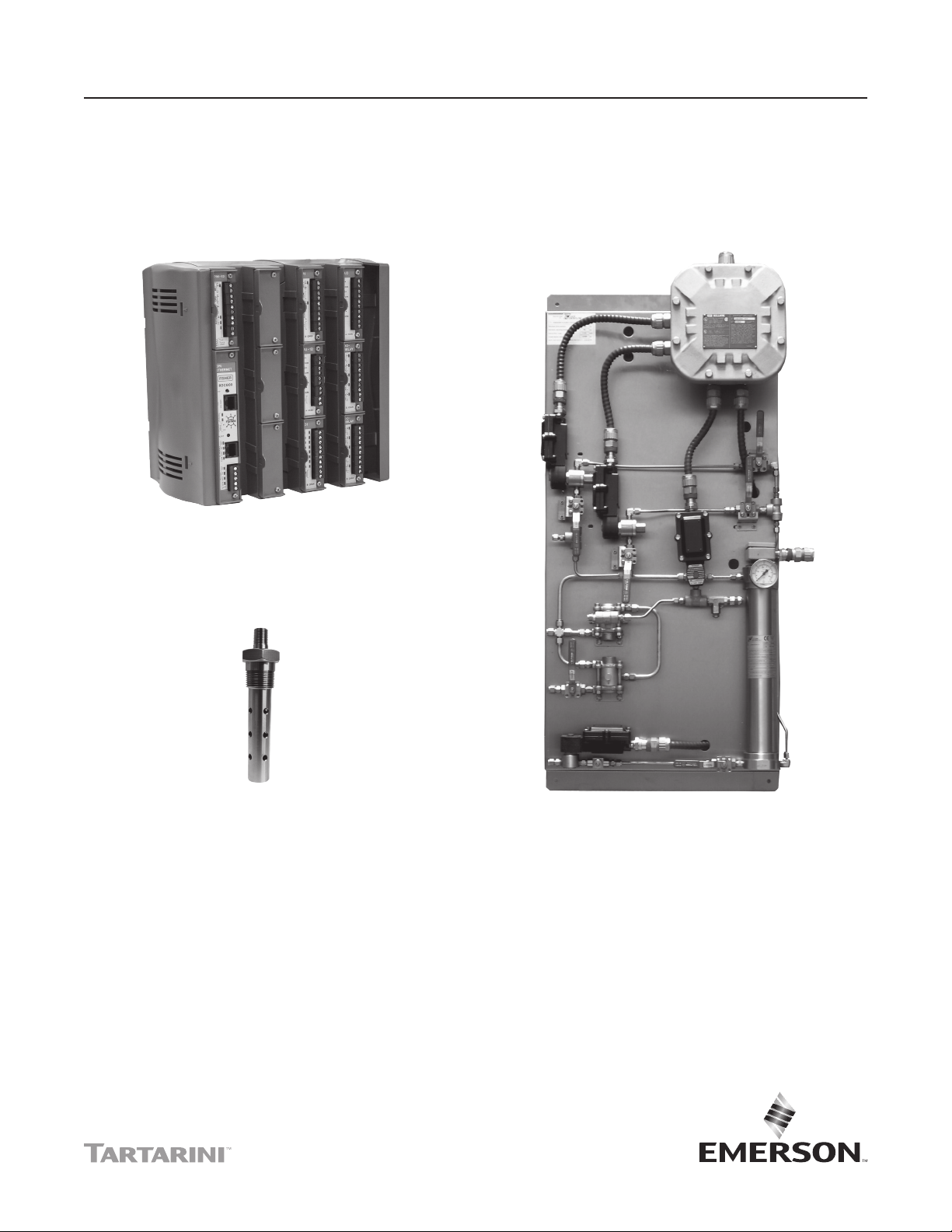
Figure 1. Type ROC809 Remote Telemetry Unit
Figure 2. Standard Wick Insert Figure 3. Type Dosaodor-D Pneumatic Panel
Introduction
Type Dosaodor-D is a computerized odorant injection
system for natural gas using patented solenoid
injector technology that eliminates the need for
plunger pumps.
Automatic calibration during operation adjusts for any
changes in mechanical components and also detects
failures for alarming. Report by exception alarming is a
congurable option.
The solenoid injectors provide odorant injection
accuracy to be maintained over the entire ow range
of the system, approaching innite turn down.
The system can also be configured to use
redundant injectors and/or an emergency backup or
bypass absorption system.
Page 2

Type Dosaodor-D
Specications
The Specications section on this page provides the ratings and other specications for Type Dosaodor-D.
Pneumatic Panel:
Material
Stainless steel plate
Installation
Wall mount
Weight
55 to 100 lbs / 25 to 45 kg
(based on configuration)
Overpressure Relief Valve
Stainless Steel with Following Rating Options:
200 psi / 13.8 bar
550 psi / 37.9 bar
870 psi / 60.0 bar
Electrical Protection
Explosion proof
Class I, Division 1 and 2 - Groups B, C, D
Class I, Zone 1 and 2 - Groups IIB+H2, IIA
Mechanical Connections
Odorant Inlet and Discharge
1/4 in. / 6.4 mm OD Tube fitting (double ferrule)
Gas Inlet and Discharge
3/8 in. / 10 mm OD Tube fitting (single ferrule)
Maximum Working Pressure
Supply: 1450 psi / 100 bar
Injection: 870 psi / 60.0 bar
Odorant Flow Rate
0.13 to 3.70 gal/hr / 0.5 to 14.0 l/hr
(0.89 to 24.97 lbs/hr at 6.75 lbs/gal)
Temperature Range
14 to 140°F / -10 to 60°C
Solenoid Valves:
Body Material
304 Stainless steel
Gasket Material
Fluorocarbon (FKM)
Valve Operation
Electromagnetic
Maximum Working Pressure
870 psi / 60.0 bar
Power Requirements
12 Vdc
Electrical Protection
Explosion proof
Class I, Division 1 - Groups A, B, C, D
Stabilizer Filter Type SA/2:
Body Material
Steel
Maximum Working Pressure
1450 psi / 100 bar
Gasket Material
Nitrile (NBR) rubber
Type ROC809 Remote Telemetry Unit:
Refer to Type ROC809 technical specifications.
please go to:
http://www.emersonprocess.com/remote/
Odorant Calibration Cylinder:
Body Material
304 Stainless steel
Maximum Working Pressure
870 psi / 60.0 bar
Maximum Emergency Design Pressure
1450 psi / 100 bar
2
Page 3
Real time and historical data can be read locally or
remotely by a laptop computer using ROCLINK 800
conguration software, or remotely using third party
SCADA products utilizing ROC or modbus protocol.
ROCLINK 800 software is available for complete
conguration and operation of the system including:
• Display of real time and historical data
• Configuration of alarms
• Archival of historical data
Benets
• Uniform distribution of odorant due to frequent
smaller injections and enhanced absorption from
the wick insertion.
• High turndown ratio. For example, one specific
configuration would evenly distribute odorant at
flow rates from 2000 to 1,000,000 SCFH / 53.6 to
26,800 Nm3/h without mechanical adjustment.
• Automatic calibration of injection system during
normal operation ensuring consistent odorization.
• Environmentally friendly with no venting of gas or
odorant while operating.
• Extremely low maintenance cost.
• Variety of redundancy and backup options for
reliable odorization.
• User friendly configuration software.
• Standard and scalable hardware platform that
supports additional station I/O for AGA flow
calculations and PID control algorithms.
Operation
The Type Dosaodor-D odorant injection system operates
on the basic principle of a fixed differential pressure and
orifice used to measure a non-compressible fluid.
Fixed differential pressure is maintained using double
cut regulation by fixed differential pressure regulators
(Type SA/2 regulators) which reference P2 and reduce
the inlet pressure of a regulating station to
P2 + ΔP. ΔP = 8.7 to 21.7 psi / 0.60 to 1.5 bar,
ΔPmax = 21.7 psi / 1.5 bar (an alternate high
pressure source can be used). This pressure loading
of the odorant calibration cylinder filled with odorant
is used to inject liquid odorant into the downstream
pipeline through an on/off valve (the fixed orifice
with a known flow coefficient that is controlled by the
automated system. The objective of the automated
control system is to maintain an injection rate specified
(1)
)
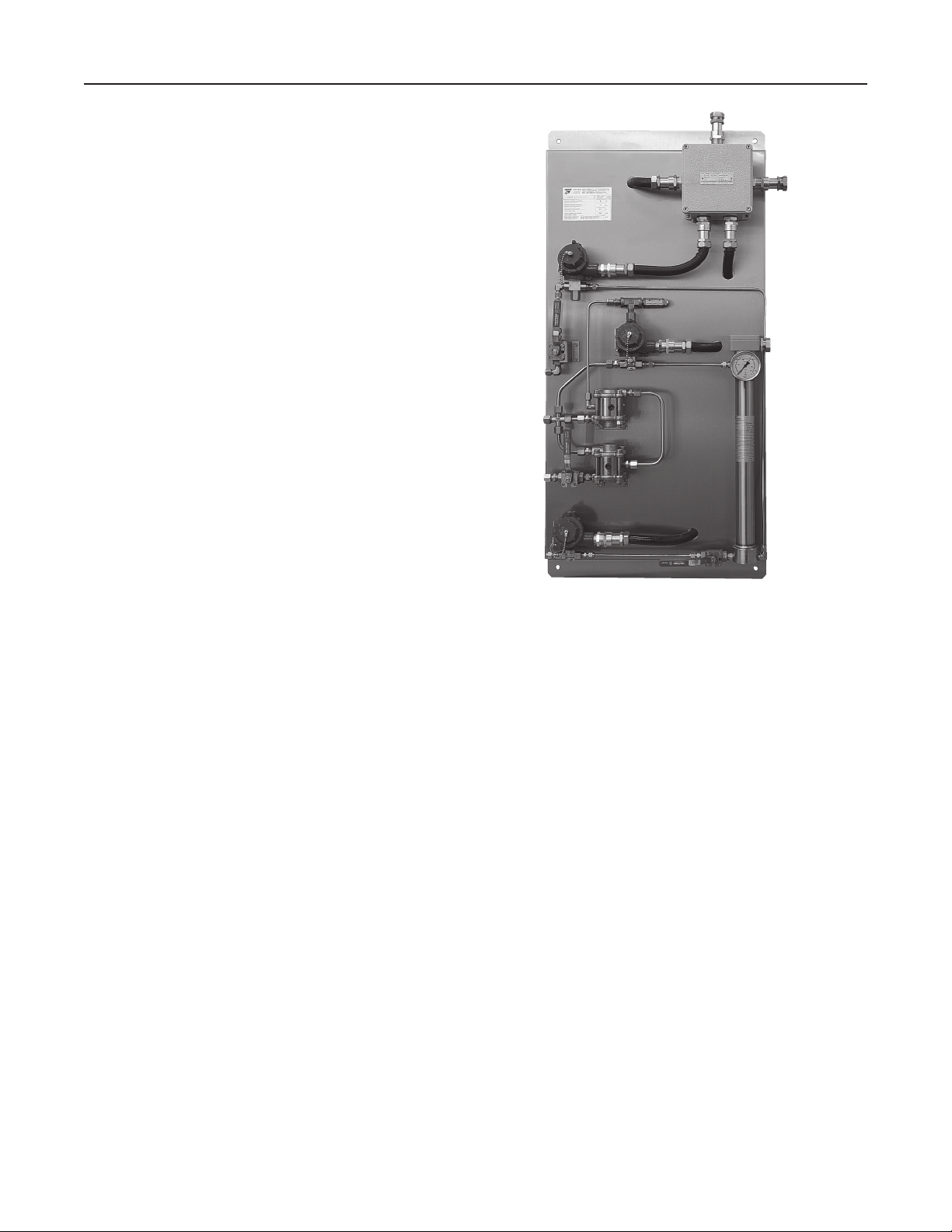
Type Dosaodor-D
Figure 4. Type Dosaodor-D Intrinsically Safe Panel
by the user which is proportional to the gas flow.
Accuracy of injection is accomplished utilizing relatively
small injections which are automatically resized over a
wide range dependent upon variations in the gas flow.
This results in a turn down ratio for the system that can
exceed 500:1 (the addition of a simple by-pass system
utilizing the odorant storage tank can allow the turn down
ratio to approach infinity). An odorant calibration cylinder
with a fixed volume is utilized to recalibrate the injection
valve flow coefficient each time the odorant calibration
cylinder is refilled.
During the refill cycle the pressure used for injection is
relieved into the downstream pipeline which eliminates
venting of gas to atmosphere or an expansion tank.
Liquid odorant refill of the odorant calibration cylinder is
typically accomplished by using all or some part of the
+ ΔP pressure to load the odorant storage tank thus
P
2
pushing the liquid out of the tank and into the odorant
calibration cylinder, ΔP = 8.7 to 21.7 psi / 0.60 to 1.5 bar.
Since the unit uses only pressure for injection there
are few moving parts in the system resulting in very
little maintenance. Relatively low cost options for both
automated and emergency redundancy for odorization
are also available.
1. Although the valve orice is xed for a specic application the valve can be adjusted manually to accommodate ow rates as small as 2 MSCFH to over 33,000 MSCFH with one injector.
3
Page 4
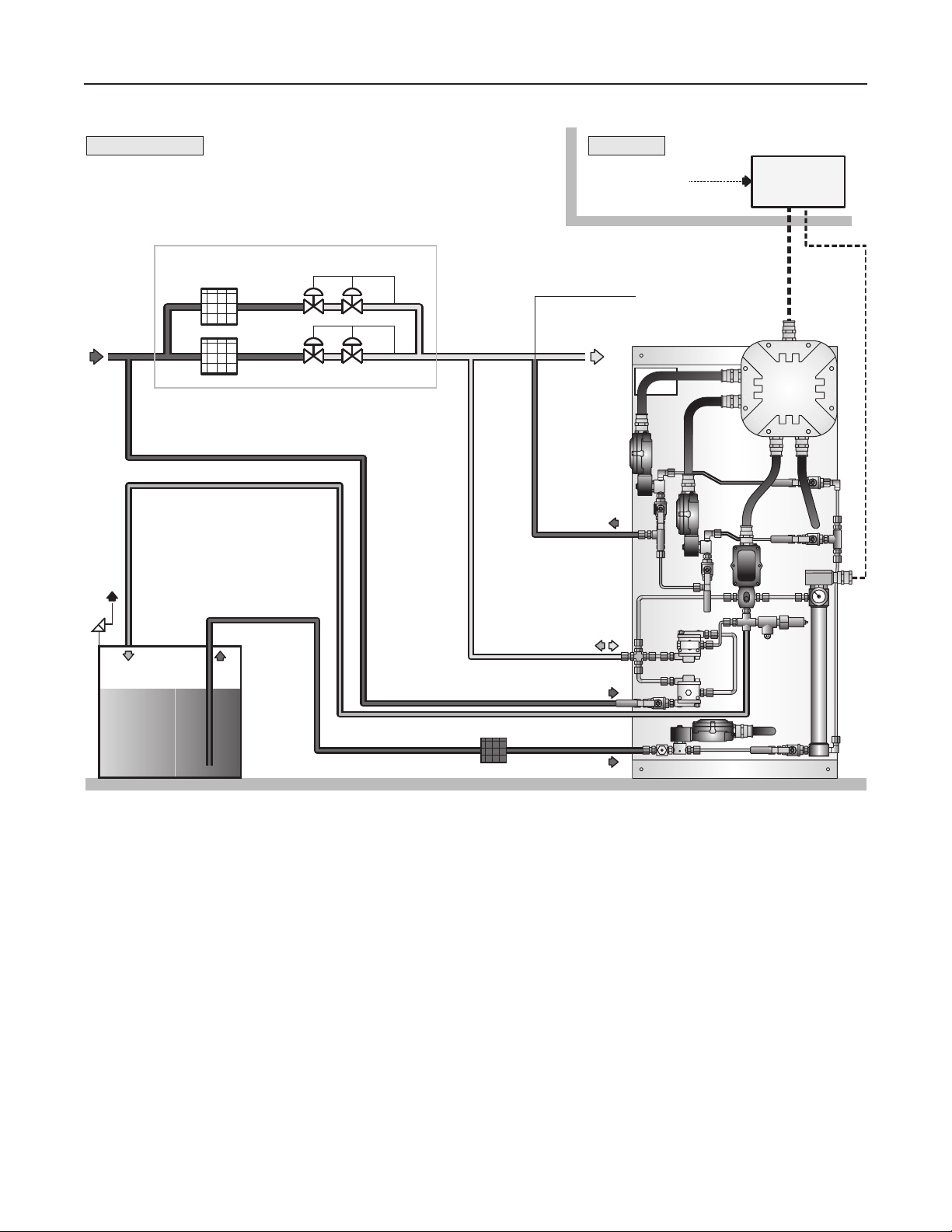
Type Dosaodor-D
HAZARDOUS AREA
REGULATING STATION
P1 P2
SAFE AREA
SIGNALS FROM
FLOW COMPUTER
LIQUID
INJECTION POINT
TYPE ROC809
PNEUMATIC PANEL
ODORANT
TANK
Figure 5. General Installation Schematic
The gas flow rate is obtained through either a corrected
gas volume pulse input or an instantaneous flow rate
analog input (4 to 20mA) signal. The gas flow rate can
also be configured manually to a fixed value. Odorant
injection rate is then calculated using accumulated flow
in order to reduce variability.
In cases where the station does not have a flow
computer, the Type ROC809 can be connected directly
to a pulse output from the turbine or an analog output
from a differential pressure transmitter (Rosemount
Types 3051, 3095, etc.).
4
Page 5

Type Dosaodor-D
HAZARDOUS AREA SAFE AREA
SIGNALS FROM
FLOW COMPUTER
REGULATING STATION
TYPE ROC809
P1 P2H P2L P2
SOLENOID VALVE SOLENOID VALVE
2
3
1
ODORANT
TANK
SUPPLIED BY SYSTEM INTEGRATOR *ASCO SOLENOID PN #JBEF8320G140V
AUTOMATED PRESSURE BALANCING SYSTEM WITH BYPASS SCHEMATIC
REGULATING STATION INLET PRESSURE
ODORANT CALIBRATION CYLINDER LOADING PRESSURE
REGULATING STATION OUTLET PRESSURE
ODORANT INJECTION PRESSURE
3
ODORANT FILTER
PNEUMATIC PANEL 1
1
2
1
2
3
Figure 6. Type Dosaodor Automated Pressure Balancing System with Bypass Schematic
Variability between the calculated and actual injection
volume is used to automatically adjust injection
parameters for any changes in the system and to
detect alarm conditions or system failure, the odorant
calibration cylinder is used to monitor the actual use
Type Dosaodor-D is designed to purge the odorant
back into the tank in the event that mechanical
maintenance is required. Odorant is pushed back
into the tank and gas is purged through the system to
absorb any remaining liquid.
of odorant. In the event of power failure, configuration
information and archived historical data are maintained.
5
Page 6

Type Dosaodor-D
Modes of Operation
The system is designed to operate in one of six modes which determine the system function and how
outputs will be controlled.
Mode of
Operation
Auto
Set system on-line
Accumulate ow
Proportional Injection
Manual and
Minimum Rate
Set system on-line
Injection proportional
to xed rate ow
Set system on-line
Start odorant calibration
cylinder ll timer
Auto Mode
System is set on-line. Injection rate is calculated
based on current flow rate input (pulse or analog
input) and configured concentration.
Manual Mode
System is set on-line. Injection rate is calculated based
on configured manual gas flow rate and concentration.
Minimum Rate Mode
System is set on-line. Injection rate is calculated based
on configured minimum flow rate and concentration.
Refill Mode
Injector is off-line. Odorant calibration cylinder is refilled
with odorant and calculation is performed to verify
injector volume rate. Once refill is complete, system
returns to prior mode (during normal operation).
Purge/Wash Mode
System is set off-line. Odorant is emptied from
odorant calibration cylinder and back to the supply
tank. During Gas Wash Cycle, solenoids are opened
to allow gas flow through the odorant calibration
cylinder and injectors. Gas Wash Cycle and Injector
Flush Cycle are available.
Rell
Purge/Wash
Set system o-line
Purge panel
of liquids
Disabled
Set system o-line
Emergency bypass
enabled (if installed)
Disabled Mode
Injector and panel functions are off-line. Emergency
bypass system enabled if available.
ROCLINK 800 Configuration Software
ROCLINK 800 Configuration Software, a Windows®
based program, enables complete configuration either
local or remote of the Type Dosaodor-D odorant
system. This allows the viewing of data in real time,
management of the historical data and control of
the alarm conditions. Connection is via serial port,
ethernet port or remote communications.
ROCLINK 800 software has an user friendly Windows
interface. The Configuration Tree navigation interface
makes accessing features quick and easy. Drop-down
menus simplify accessing the software functions.
Dialog boxes and drop-down list boxes help direct
selections and data entry. Actions can be performed
with the keyboard or a mouse.
The main specifications of the ROCLINK 800 software
are as follows:
• MS Windows interface
• Single configuration point for all connectable
odorizing units
• Complete configuration for each parameter of the
odorizer system
• Display of real time data, historical data and alarms
6
Page 7

Type Dosaodor-D
Figure 7. Type Dosaodor-D Configuration Display
Minimum Software and Hardware
Requirements
• Pentium®-class processor (233 MHz or
greater recommended)
• CD-ROM drive
• Windows 98, ME, NT 4.0 (Service Pack 6), 2000
(Service Pack 2) or XP
• 64 MB of RAM (Random Access Memory)
• 15 to 75 MB of available hard disk space,
depending on operating system and revision level
Configuration Selection
The purpose of this section is to facilitate Ordering
Guide selections.
The minimum requirements for product installation are
as follows:
1. There must be a differential pressure of at
least 14.5 psi / 1 bar between upstream and
downstream of the regulation station.
2. The tank containing the odorant fluid must be
pressurized. The odorant storage tank is usually
pressurized by the system up to 8.7 to 21.7 psi /
0.60 to 1.5 bar higher than outlet pressure.
3. Downstream pressure must be maintained as
constant as possible in order to maintain accuracy
of odorant injection.
If these conditions are not fulfilled, please contact your
Emerson representative for alternate configurations.
A) Base Panel
A6 Option
• Construction based on North American standards
with CSA certified components.
7
Page 8

Type Dosaodor-D
• Configuration does not include the Type ROC809
controller necessary for the functioning of the
system. The Type ROC809 is available from the
Remote Automation Solutions.
B) Model (Select One)
B1 Option – Single Injector
• This option provides only one injection solenoid.
B2 Option – Dual Injector
• This option provides two injection solenoids
installed in parallel for redundancy in the event
of an injector failure.
• An alternate use of dual injectors is for increased
turndown. In the event the flow conditions
vary, it is possible to create a low flow injector
and a high flow injector for scenarios such as
seasonal loads.
Notes
The two solenoid valves do not operate
simultaneously. It is therefore not
possible to use the B2 conguration in
order to serve two gas transport lines at
the same time.
The two solenoid valves can work in
exchange mode. When the desired
quantity of odorant (determined by a
parameter accessible by the user) is
injected, the solenoid valve that has just
operated will go into rest mode leaving
the task of injection to the alternate
solenoid valve.
C) Maximum Odorant Injection Rate (Select One)
The injector solenoid is selected based on the
maximum gas ow rate and the desired odorant
concentration. The following information and
calculation will determine this value.
From a theoretical viewpoint, this takes into
account the following:
International Standard Unit
C = concentration of odorant (mg/Sm³)
Qg = maximum gas ow rate (Sm³/h)
ρ = density of liquid odorant (kg/dm³)
Qo = maximum odorant ow rate (l/h)
Qo = C * Qg / (1,000,000 * ρ)
For the purposes of proportioning, we may consider
the odorant density as ρ = 1 kg/dm3.
For example, if the maximum line ow is
90,000 Sm³/h and the odorant used is THT (with
a desired concentration of 40 mg/Sm³) then the
appropriate option from the table below is C4.
By formula:
3
Qo =
40 mg
3
Sm
1 kg
1,000,000 mg
90,000 Sm
h
dm
1 kg
3
1 l
1 dm
Qo = 3.6 l/hr
Using the equation result, the fourth column of Table 1
shows the first value exceeding the calculated value
which will suggest which configuration to choose (in
the specific case of C4).
3
Table 1. Maximum Odorant Injection Rate using International Standard Unit
ORDER FORM CONFIGURATION
C1 12,500 50,000 0.13 / 0.5
C2 25,500 100,000 0.26 / 1.0
C3 50,000 200,000 0.53 / 2.0
C4 100,000 400,000 1.06 / 4.0
C5 150,000 600,000 1.59 / 6.0
C6 200,000 800,000 2.11 / 8.0
C7 250,000 1,000,000 2.64 / 10.0
C8 300,000 1,200,000 3.17 / 12.0
C9 350,000 1,400,000 3.70 / 14.0
8
40 mg/Sm
MAXIMUM GAS VOLUME, Sm
3
(THT) 10 mg/Sm3 (Mercaptan)
3
/h
MAXIMUM INJECTION RATE,
GAL/HR / L/HR
Page 9

Type Dosaodor-D
If different odorant concentrations from those specified
in the table (40 and 10 mg/Sm³) are used, it is
advisable to use the given formula and fourth column
of Table 2 (Maximum Injection Rate) to determine the
correct configuration.
For example, if the maximum line flow is
15,000 Sm³/h and the odorant used is THT (with
a desired concentration of 38 mg/Sm³) then the
appropriate option is C2.
3
Qo =
38 mg
3
Sm
1 kg
1,000,000 mg
15,000 Sm
h
dm
1 kg
3
1 l
1 dm
3
Qo = 0.57 l/hr
North America Standard Unit
C = concentration of odorant (lbs/MMSCF)
ρ = density of liquid odorant (lbs/gal)
Qg = maximum gas flow rate (MMSCF/h)
Qo = maximum odorant flow rate (gal/h)
Qo = C * Qg / ρ
For example, if the maximum line flow is 7 MMSCF/h and
the odorant used is THT (with a desired concentration
of 1.0 lbs/MMSCF) then the appropriate option from
Table 2 is C4.
By formula:
Qo = = 1.04 gal/hr
1 lb
MMSCF
7 MMSCF
h
gal
6.75 lbs
Using the equation result, the fth column of Table 2
shows the rst value exceeding the calculated value
which will suggest which conguration to choose (in
the specic case of C4).
If dierent odorant concentrations from those specied
in the table (1.0 and 0.5 lbs/MMSCF) are used it is
advisable to use the given formula and the table to
determine the correct conguration.
If a dierent density is required, use the fourth column
for selection.
For example, if the maximum line ow is 20 MMSCF/h
and the odorant used is mercaptan (with a desired
concentration of 0.6 lbs/MMSCF) then the appropriate
option from Table 2 is C6.
Qo = = 1.78 gal/hr
0.6 lb
MMSCF
20 MMSCF
h
gal
6.75 lbs
At 6.75 lbs/gal is equivalent to:
1.78 gal
h
6.75 lbs
gal
= 12 lbs/hr
I) Maximum Working Pressure (Select One)
Select based on maximum working pressure
(downstream pressure, in the injection area). The
density constraint is required to let the "oating
system" present in the odorant calibration cylinder
work properly.
I1 Option
At 6.75 lbs/gal is equivalent to:
1.04 gal
h
Table 2. Maximum Odorant Injection Rate using North American Standard Unit
ORDER FORM
CONFIGURATION
C1 0.89 1.78 0.13 / 0.5 0.89
C2 1.78 3.57 0.26 / 1.0 1.78
C3 3.57 7.13 0.53 / 2.0 3.57
C4 7.13 14.27 1.06 / 4.0 7.13
C5 10.70 21.40 1.58 / 6.0 10.70
C6 14.27 28.53 2.11 / 8.0 14.27
C7 17.83 35.67 2.64 / 10.0 17.83
C8 21.40 42.80 3.17 / 12.0 21.40
C9 24.97 49.93 3.70 / 14.0 24.97
6.75 lbs
gal
MAXIMUM GAS VOLUME, MMSCF/H
1.0 lbs/MMSCF (THT)
= 7 lbs/hr
0.5 lbs/MMSCF
(Mercaptan)
Maximum injection pressure equal to 200 psi /
13.8 bar. A requirement for functioning is that
the density of the liquid odorant is >=5.8 lbs/gal /
0.70 kg/dm
3
.
MAXIMUM
INJECTION RATE,
GAL/HR / L/HR
MAXIMUM
INJECTION RATE, LBS/HR
(AT 6.75 LBS/GAL)
9
Page 10

Type Dosaodor-D
B1 VERSION (SINGLE INJECTOR)
22 / 560
20.1 / 510
44.5 /
1130
46.5 /
1180
B2 VERSION (DUAL INJECTOR)
22 / 560
20.1 / 510
44.5 /
1130
BRACKET
13.8 / 350
OPTIONAL STAINLESS STEEL CABINET
DIMENSIONS IN IN. / mm: 37 x 18.2 x 78.4 / 940 x 460 x 1990
5.9 /
150
7.9 /
200
IN. /
mm
46.5 /
1180
Figure 8. Pneumatic Panel Overall Dimensions
10
Page 11

Type Dosaodor-D
I2 Option
Maximum injection pressure equal to 550 psi /
37.9 bar. A requirement for functioning is that the
density of the liquid odorant is >=
0.55 kg/dm3.
I3 Option
Maximum injection pressure equal to 870 psi /
60.0 bar. A requirement for functioning is that
the density of the liquid odorant is >= 5.8 lbs/gal
0.70 kg/dm3.
M) Installation Options - Wick insert (Select One)
Select based on pipe size.
Option – Standard wick insert (for downstream
size < 10 in. (NPS 10 / DN 250)
Option – Long wick insert (for downstream
size >= 10 in. (NPS 10 / DN 250)
4.6 lbs/gal /
Ordering Guide
O) Installation Options - Fittings (bulk brand
as standard)
If the O item is not selected the standard fittings
will be used (bulk brand).
Option – Swagelok ttings
Stainless steel Swagelok fittings.
Automation software and license key
/
Software for management of the Type Dosaodor-D
system compatible with Type ROC809 platform hardware
and Type Dosaodor-D license key.
The software may be ordered individually or in
combination with the pneumatic panel.
The pneumatic panel must be ordered with the
automation software and license key.
Optional Component - Cabinet for pneumatic panel
A stainless steel cabinet may be selected as an option.
Base Panel
A6 Type Dosaodor-D odorant injection system
completed with:
Pneumatic Panel
• Stainless steel panel
• Installation kit (bracket, pipe connection,
valves, etc.)
• Explosion proof Class I, Division 1 and
2 - Groups B, C, D - Class I, Zone 1 and 2 Groups IIB+H2, IIA
• Included 1/4 in. fitting connectors for 3/8 and
1/4 in. / 9.5 and 6.4 mm OD tubing
Model (Select One)
B1 Single Injector
B2 Dual Injector
Maximum Odorant Injection Rate (Select One)
C1 0.13 gal/hr / 0.5 l/hr
C2 0.26 gal/hr / 1.0 l/hr
C3 0.53 gal/hr / 2.0 l/hr
C4 1.06 gal/hr / 4.0 l/hr
C5 1.58 gal/hr / 6.0 l/hr
C6 2.11 gal/hr / 8.0 l/hr
C7 2.64 gal/hr / 10.0 l/hr
C8 3.17 gal/hr / 12.0 l/hr
C9 3.70 gal/hr / 14.0 l/hr
Maximum Working Pressure (Select One)
I1 200 psi / 13.6 bar
(odorant ρ >= 5.8 lbs/gal / 0.70 kg/dm
I2 550 psi / 37.9 bar
(odorant ρ >= 4.6 lbs/gal / 0.55 kg/dm3)
I3 870 psi / 60.0 bar
(odorant ρ >=5.8 lbs/gal / 0.70 kg/dm3)
Installation Options - Wick Insert (Select One)
Standard Wick Insert
(for downstream size < 10 in. (NPS 10 / DN 250)
Long Wick Insert
(for downstream size >= 10 in. (NPS 10 / DN 250)
Installation Options - Fittings (Bulk Brand as Standard)
Swagelok Fittings
Automation Software and License Key
Software for pneumatic panel control, available with
Type ROC809 plus Type Dosaodor-D license key
Optional Component
Cabinet for Pneumatic Panel
Stainless steel cabinet for pneumatic panel
- continued -
3
)
11
Page 12

Type Dosaodor-D
Ordering Guide (continued)
Type ROC809 Configurations and Options
Required Components
Quantity Description
1
1
2
1
1
Type ROC809E Controller
Type ROC800 12 Vdc Power Supply
Type ROC800 Discrete Relay Output Card
Type ROC800 Discrete Input Card
Type DS800 Runtime License
Select Input Card Type for Flow Rate Input
(Choose Only One for Configuration)
Quantity Description
1
1
Type ROC800 Analog Input Card
Type ROC800 Pulse Input Card
Optional Equipment
Quantity Description
1
Type ROCLINK800 Software
(at least 1 license required)
1
1
1
1
1
1
1
Type ROC800 LOI Cable
Type ROC800 Ethernet Crossover Cable
Type ROC800 RS232 Comm Module
Type ROC800 RS485 Comm Module
Type ROC800 14.4 Dial-up Modem Comm
Type ROC800 Analog Output Card
Power Supply Charger 12 Vdc
Webadmin.Regulators@emerson.com
Tartarini-NaturalGas.com
Emerson Automation Solutions
Americas
McKinney, Texas 75070 USA
T +1 800 558 5853
+1 972 548 3574
Europe
Bologna 40013, Italy
T +39 051 419 0611
Emerson Process Management s.r.l
Emerson Automation Solutions - Stabilimento di/Site of: Castel Maggiore - Bologna
Sede Legale/Legal Entity: Piazza Meda 5, 20121 Milano, Italy
Sede Amministrativa/Administrative Headquarters: OMT Tartarini, Via Clodoveo Bonazzi 43,
40013 Castel Maggiore (Bologna), Italy
C.F. - P.I. e R.I. di MI 13186130152 - REA di MI/n.1622916
Direz. e Coord. (art. 2497 bis CC): EMERSON ELECTRIC CO. St. Louis (USA) Socio Unico
Facebook.com/EmersonAutomationSolutions
LinkedIn.com/company/emerson-automation-solutions
Twitter.com/emr_automation
Asia Pacic
Singapore 128461, Singapore
T +65 6777 8211
Middle East and Africa
Dubai, United Arab Emirates
T +971 4 811 8100
D103095X012 © 2007, 2021 Emerson Process Management Regulator
Technologies, Inc. All rights reserved. 03/21.
The Emerson logo is a trademark and service mark of Emerson
Electric Co. All other marks are the property of their prospective owners.
Tartarini™ is a mark owned by one of the companies in the Emerson
Automation Solutions business unit of Emerson Electric Co.
The contents of this publication are presented for informational purposes
only, and while every eort has been made to ensure their accuracy, they
are not to be construed as warranties or guarantees, express or implied,
regarding the products or services described herein or their use or
applicability. All sales are governed by our terms and conditions, which
are available upon request. We reserve the right to modify or improve the
designs or specications of such products at any time without notice.
Emerson Process Management Regulator Technologies, Inc. does
not assume responsibility for the selection, use or maintenance of any
product. Responsibility for proper selection, use and maintenance of any
Emerson Process Management Regulator Technologies, Inc. product
remains solely with the purchaser.
 Loading...