

Page 1
ROC800:ROC800L Product Data Sheet
D301678X012 April 2020
Remote Automation Solutions
ROC800L Remote Operations Controller
The ROC800L Remote Operations Controller (ROC800L) is a
microprocessor-based controller that provides the functions
required for a variety of field automation applications,
including liquid measurement. The ROC800L monitors,
measures, and controls equipment in a plant or remote
environment. The ROC800L is ideal for any application
requiring flow computation; Proportional, Integral, and
Derivative (PID) control loops; logic sequencing control; and
up to six liquid meter runs. Two versions of the ROC800L are
available: the ROC809L (with nine module slots) and the
ROC827L (which is expandable from three to 27 module
slots).
Factory installed liquid measurement user programs provide
the American Petroleum Institute (API) calculations in
accordance with Manual for Petroleum Measurement
Systems (MPMS). The liquid measurement user programs
perform the following functions:
▪ Liquid Calculations – Accurately measures liquids
flowing through a meter, and performs volume
corrections based on density, temperature, and
pressure measurements.
▪ Batching – Allows you to configure and schedule
multiple batches to record and control the flow of a
liquid. Batch accuracy is improved through the
retroactive calculation and re-calculation using userdefined variables.
▪ Proving – Performs meter proving by operating a 4-way
control valve, calculating a new meter factor, and
storing meter factor information on up to 24 products
for each of up to six meters. Unidirectional,
bidirectional, large volume, small volume, and master
meter proving are supported. A prover densitometer is
also supported for inferred mass proving.
▪ Reporting – Generates printable reports in compliance
with API MPMS Chapter 12.2.2, 12.2.3, and 21.2. Userdesigned reports can be created using ROCLINK™ 800
Configuration Software.
For additional information on each of the included
programs, refer to Product Data Sheet ROC800:SW1.
The ROC800L has the following features:
▪ Rugged, reduced-maintenance hardware.
▪ High isolation, surge and short circuit protection.
▪ Low power consumption.
▪ Wide operation temperature (–40 to 75C).
▪ Up to 27 easily installed modular I/O cards.
▪ Versatile serial and Ethernet communications.
▪ Class I, Div. 2 & Zone 2 hazardous location approval.
▪ Metering station support for up to 6 liquid runs and
ability to support up to 6 gas runs with an optional AGA
license key installed.
▪ Easy-to-use ROCLINK 800 configuration software.
▪ Custom programming with Function Sequence Tables
(FSTs) or DS800 Development Suite, which allows you
to build IEC 61131-3 compliant programs for use with
the ROC800L.
The Base Unit
The Polycarbonate/Acrylonitrile Butadiene Styrene (PC/ABS)
plastic housing has removable wire channel covers to
protect the wiring terminals. DIN rail mounting allows the
ROC800L to mount on an enclosure backplane. The rugged
housing is suitable for use over the complete extended
temperature range.
The ROC800L controller eliminates the need for fuses on the
I/O and communications modules through the extensive
use of the latest technology in short-circuit protection. This
results in less maintenance.
The ROC800L economizes its power consumption for
normal operation through the use of internal 3.3 volt
electronics.
The ROC800L uses a power input module to convert
external input power to the voltage levels required by the
ROC800L’s electronics. Two power input modules are
available for the ROC800L: one for 12 volt dc input power
and one for 24 volt dc input power.
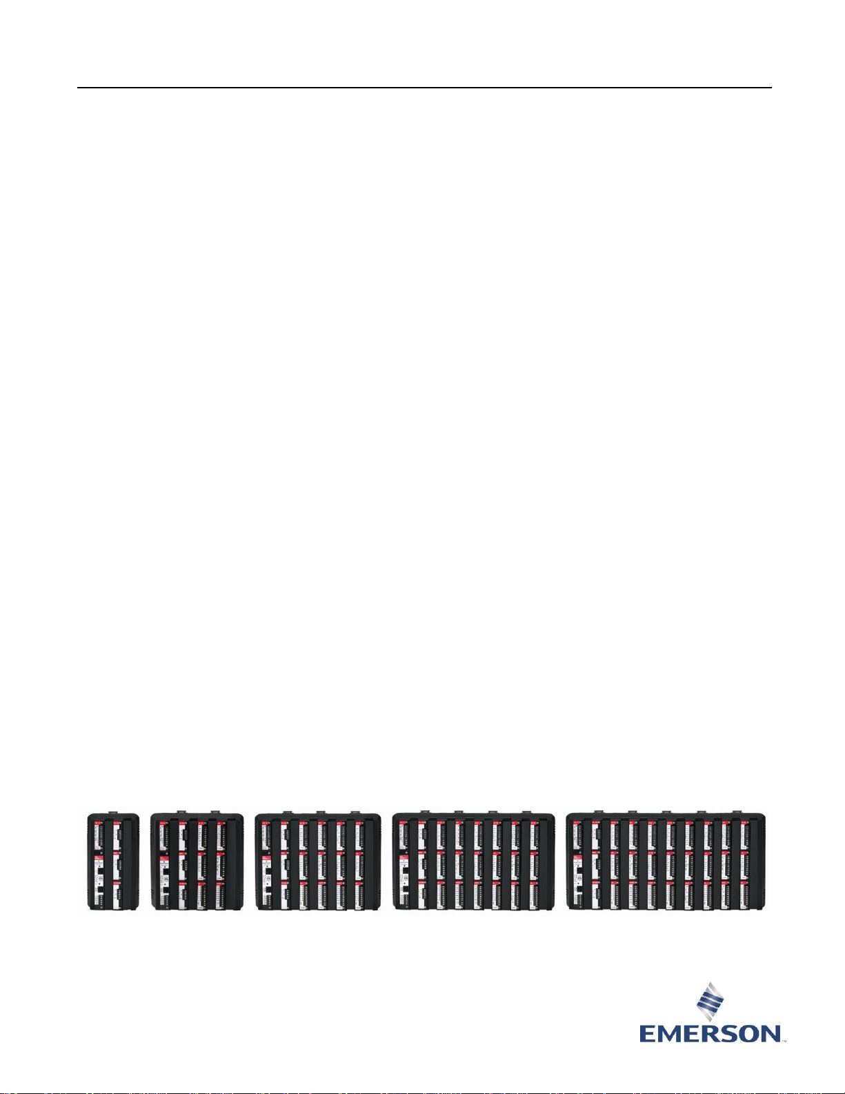
ROC827L (with 0, 1, 2, 3, and 4 expansion I/O backplanes)
Page 2

April 2020 ROC800:ROC800L
2 www.Emerson.com/RemoteAutomation
ROC809L
The ROC809L houses a backplane that supports a ROC800Series 2 central processing unit (CPU), a power input
module, Input/Output (I/O) modules, and communication
modules. The ROC809L has nine slots for modules: the first
three slots are for either communication or I/O modules, and
the remaining six slots are for I/O modules only.
ROC827L
The ROC827L houses a backplane that supports a ROC800Series 2 central processing unit (CPU), a power input
module, and up to three modules (communications or I/O).
You can expand the ROC827L by adding up to four
expansion I/O backplanes. Each expansion I/O backplane has
six slots to house I/O modules. The three module slots of the
base ROC827L—when combined with a maximum of four
expansion I/O backplanes (which contain six slots each)—
allow expansion of up to 27 slots.
Memory
The ROC800L has four types of memory:
▪ Boot Flash – System initialization and diagnostics.
▪ Flash – Firmware image and report files.
▪ SRAM (Static Random Access Memory) –
Data Logs and configuration.
▪ SDRAM (Synchronous Dynamic Random Access
Memory) – Firmware execution and execution memory.
The 32-bit microprocessor and the Real-Time Operating
System (RTOS) provide both hardware and software
memory protection.
Firmware
The firmware resides in flash memory and contains the
operating system and application software. The CPU module
provides battery-backed SRAM (Static Random Access
Memory) for saving the configuration, events, alarms, and
historical logs.
The firmware has a database for events, alarms, and history
that stores the last 450 events, the last 450 alarms, and 35
days of hourly records. The weights and measures database
stores up to 1000 weights and measures events. The history
database holds up to 240 points in 13 segments, providing
over 224,000 unique entries. You can configure each
segment to archive at different time intervals and with
different contract hours.
Meter Runs and Stations
The ROC800L supports up to six liquid meter runs and up to
six stations. You can group meter runs and stations in any
combination. Typically, you associate meter runs with a
station if the meter runs have common parameters, such as
fluid type and base temperature.
Grouping similarly configured meter runs with stations
provides significant benefits in batching, configuration, and
reporting. For example, you can configure parameters at the
station level. The system then applies those configuration
parameters to all meters belonging to the station, reducing
configuration time.
You can configure the ROC800L either to provide individual
reports for each meter or to generate station reports that
consolidate multiple meters. Station reports eliminate
redundant meter run data, reduce the need to download
and upload, and result in a more efficient reporting process.
Communications
The ROC800L provides up to six communication ports. Three
communication ports are built-in:
▪ Local Operator Interface – LOI.
▪ Ethernet – Comm1.
▪ EIA-232 (RS-232) – Comm2.
The Local Operator Interface (LOI) port’s EIA-232 (RS-232D)
standard RJ-45 connector provides a direct link between the
ROC800L and a personal computer.
You can install up to three communication modules to
provide additional ports for communicating with a host
computer or other devices. The ROC800L accommodates
three modules in any combination of the following types:
▪ EIA-232 (RS-232) for point-to-point asynchronous serial
communications.
▪ EIA-422/EIA-485 (RS-422/RS-485) for
asynchronous serial communications,
EIA-422 for point-to-point, EIA-485 for
multiple-point, 2- and 4-wire.
▪ Dial-up modem for communications over a telephone
network.
The ROC800L allows the use of a variety of communication
protocols, including ROC Plus or Modbus Slave (ASCII or
RTU) on all ports. In addition to these, the ROC800L allows
the use of Modbus host on all ports except the LOI and
Ethernet ports.
The Ethernet port allows the following communication
protocols:
▪ ROC Plus protocol.
▪ Modbus encapsulated in TCP/IP protocol (slave only).
▪ Modbus TCP/IP protocol (slave only).
▪ DS800 Development Suite 800 software
communications.
Page 3

ROC800:ROC800L April 2020
www.Emerson.com/RemoteAutomation 3
Input/Output Options
The isolated I/O modules can be added to satisfy a wide
variety of field I/O requirements. You can add up to nine I/O
modules to the ROC809L and up to 27 modules to the
ROC827L with the optional expansion I/O backplanes. I/O
modules include:
▪ Analog Inputs (AI)
▪ Analog Outputs (AO)
▪ Alternating Current Inputs/Outputs (AC I/O)
▪ Advanced Pulse Module (APM)
▪ Discrete Inputs (DI)
▪ Discrete Outputs (DO)
▪ Discrete Output Relay (DOR)
▪ HART Inputs/Outputs (HART)
▪ Multi-Variable Sensor I/O (MVS I/O)
▪ Pulse Inputs (PI) – High or Low Speed
▪ RTD Inputs (RTD)
▪ Thermocouple I/O
Module Installation
Installation and replacement of any I/O or communication
module is easily accomplished by removing the two captive
screws accessible from the front of the unit. Some modules
are hot-swappable, meaning you can remove the module
and install another module of the same kind while under
power. The new module acquires the previous module’s
configuration. Some modules are hot-pluggable, meaning
they may be installed directly into unused module slots
under power. To determine if a module is hot-swappable or
hot-pluggable, refer to the specific module’s product data
sheet.
Software
ROCLINK 800 configuration software is an easy-to-use
Windows® based application program used to configure,
calibrate, monitor and retrieve historical data from the
ROC800L. The ROC800L is supported by ROCLINK 800
version 1.88 or later.
The software uses the Windows style navigation tree with
drop-down menus and context-based dialog boxes. It is well
organized and functional for the standard station and meter
run firmware application.
ROCLINK 800 also provides program customization through
Function Sequence Tables (FSTs). FSTs may be built from a
library of functions and commands to provide special control
capability, mathematical and logical operations, and
database access operations.
The software provides security for controlling access to
functions in ROCLINK 800 software. Passwords restrict logon to both ROCLINK 800 and the ROC800L controller.
Options
▪ I/O and Communications – The ROC800L supports a
wide variety of I/O and communications modules to suit
many applications.
▪ ROC Keypad Display – The ROC Keypad Display allows
local users to view and change parameters in the
ROC800L.
▪ Power Input Modules – The ROC800L unit supports 12
volt dc or 24 volt dc power input modules, which
provide 12 volt dc power to the backplane.
▪ License Keys – Optional license keys are available that
grant access to corresponding applications, such as
DS800 Development Suite Software and gas meter run
calculations.
▪ Orifice and Linear Meter Calculations – Up to six gas
meter runs using American Gas Association (AGA) or
ISO calculations for any combination of orifice, turbine,
ultrasonic, and/or Coriolis meter types are enabled with
an optional license key. This allows the ROC800L to
measure up to six gas meter runs simultaneously with
the liquid meter runs.
▪ Development Suite 800 (IEC 61131-3) – DS800
Development Suite Software is an integrated
development environment allowing you to build IEC
61131-3 compliant programs. The DS800 software can
be used to develop programs independent of ROCLINK
800 Configuration Software and is enabled with an
optional license key. For more information, refer to
Product Data Sheet DS800.
Compatibility
The ROC800L uses a ROC800-Series 2 CPU and Series 2compatible modules. For module compatibility questions,
refer to the individual module’s product data sheet.
Page 4

April 2020 ROC800:ROC800L
4 www.Emerson.com/RemoteAutomation
ROC800L Remote Operations Controller
CPU Module
Processor
32-bit microprocessor based on the Motorola MPC862 Quad Integrated Communications
Controller (PowerQUICC™) PowerPC processor running at 65 MHz
Memory
Boot Flash
256 KB for system initialization and diagnostics
Flash
16 MB for firmware image and report files
SRAM
2 MB for historical data logs and configuration
Synchronous
DRAM
32 MB for firmware execution and execution memory
Battery Backup
Type
Sanyo 3 V CR2430 lithium, user-replaceable
Normal use life
10 years while power is applied to unit
Backup life
1 year minimum while maintaining RTC and SRAM data and no power
is applied to unit
Shelf life
10 years
Clock
Type
32 KHz crystal oscillator with regulated supply, battery-backed
Year/Month/Day and Hour/Minute/Second
Clock Accuracy
0.01%
Watchdog Timer
Hardware monitor expires after 3 seconds and resets the processor
Diagnostics
Board
Temperature
Accuracy
1% typical, 2% maximum
Voltage Monitor
Accuracy
0.75% typical, 1% maximum
Light-Emitting Diodes (LEDs)
Status
Indicates normal function, low battery voltage, system AI alarm, and
firmware status.
COL (Ethernet)
Indicates that packet collisions occurred when transmitting or
receiving data through the Ethernet port
ACT (Ethernet)
Indicates that the ROC800L is transmitting or receiving data through
the Ethernet port
DTR (RS-232)
Data Terminal Ready
RTS (RS-232)
Request to Send
Tx (RS-232)
Indicates that the ROC800L is transmitting data through an EIA-232
(RS-232) communication port
Rx (RS-232)
Indicates that the ROC800L is receiving data through an EIA-232 (RS-
232) communication port
Communications
Ports on CPU module
LOI (Local
Operator
Interface)
EIA-232D (RS-232D) Standard. 115.2 Kbps maximum data rate
Page 5

ROC800:ROC800L April 2020
www.Emerson.com/RemoteAutomation 5
Ethernet
10BASE-T twisted pair. IEEE multi-segment 10 MB/second baseband
Ethernet
Maximum
Segment
100 m (330 ft)
EIA-232 (RS-232)
PORT
Single. 115.2 Kbps maximum data rate
Communication Modules
(optional)
EIA-232 (RS232)
Single. 115.2 Kbps maximum data rate. For more information, refer to
Product Data Sheet ROC800:COM.
EIA-422/485
(RS-422/485)
Single. 115.2 Kbps maximum data rate. For more information, refer to
Product Data Sheet ROC800:COM.
Dial-up Modem
Module
Single. 14.4 Kbps maximum data rate. For more information, refer to
Product Data Sheet ROC800:COM.
Network Radio
Module
Provides a wireless solution for importing and/or exporting over-theair messages and information. For more information, refer to Product
Data Sheet ROC800:NRM.
Protocols
LOI Port
ROC Plus, Modbus slave (ASCII or RTU), DS800 Development Suite 800
software communications
EIA-232 and EIA422/485
ROC Plus, Modbus host and slave (ASCII or RTU), DS800 Development
Suite 800 software communications
Ethernet Port
ROC Plus, Modbus host and slave (ASCII or RTU) encapsulated in TCP/IP
or via TCP/IP, DS800 Development Suite 800 software
communications
Dial-up Modem
ROC Plus, Modbus slave (ASCII or RTU)
Inputs/Outputs Modules (optional)
Alternating Current
Input/Output
6 channels: selectable as input or output. For more information, refer to Product Data Sheet
ROC800:ACIO.
Analog Input-12
4 channels; 12 bits of resolution. For more information, refer to Product Data Sheet
ROC800:AI.
Analog Input-16
4 channels; 16 bits of resolution. For more information, refer to Product Data Sheet
ROC800:AI.
Analog Output
4 channels. For more information, refer to Product Data Sheet ROC800:AO.
Advanced Pulse Input
4 channels pulse, 2 prover. For more information, refer to Product Data Sheet ROC800:APM.
Discrete Input
8 channels. For more information, refer to Product Data Sheet ROC800:DI.
Discrete Output
5 channels. For more information, refer to Product Data Sheet ROC800:DO.
Discrete Output Relay
5 channels. For more information, refer to Product Data Sheet ROC800:DOR.
HART Input/Output
4 channels, each capable of communications with up to 5 HART devices (when in input
multi-drop mode. For more information, refer to Product Data Sheet ROC800:HART.
MVS Input/Output
Supports up to 6 sensors. For more information, refer to Product Data Sheet ROC800:MVS.
Pulse Input
2 channels; user-selectable high speed or low speed per channel. For more information,
refer to Product Data Sheet ROC800:PI.
RTD Input
2 channels. For more information, refer to Product Data Sheet ROC800:RTD.
Thermocouple Input/Output
4 channels. For more information, refer to Product Data Sheet ROC800:TC2.
Page 6

April 2020 ROC800:ROC800L
6 www.Emerson.com/RemoteAutomation
Power
ROC809L Input Power
Series 2 Base Unit (power
module, backplane, and
CPU)
12 Vdc Power Input
Module (PM-12)
88 mA. For more information, refer to
Product Data Sheet ROC800:PIM.
24 Vdc Power Input
Module (PM-24)
102 mA. For more information, refer to
Product Data Sheet ROC800:PIM.
ROC827L Input Power
Series 2 Base Unit (power
module, backplane, and
CPU)
12 Vdc Power Input
Module (PM-12)
104 mA. For more information, refer to
Product Data Sheet ROC800:PIM.
24 Vdc Power Input
Module (PM-24)
110 mA. For more information, refer to
Product Data Sheet ROC800:PIM.
ROC827L Input Power
(continued)
Series 2 Expansion I/O
Backplane
12 Vdc Power Input
Module (PM-12)
25 mA
24 Vdc Power Input
Module (PM-24)
12.5 mA
Note: To determine the unit’s final input power requirements, add the input power requirements of the base unit, any
optional expansion I/O backplanes, and all appropriate communication or I/O modules together. Input power
requirements for individual modules are listed on each module’s product data sheet.
Physical
Dimensions
ROC809L
241 mm H by 244 mm W by 174 mm D (9.5 in. H by 9.6 in. W by 6.85
in. D). Allow an addition depth of 19 mm (0.75 in.) for cables.
ROC827L
Width
Each End Cap
27.1 mm (1.07 in.)
Base Unit
93.2 mm (3.67 in.)
Expansion I/O
Backplane
93.2 mm (3.67 in.)
Height
241 mm (9.5 in.)
Depth
174 mm (6.85 in.). Allow an additional 19 mm
(0.75 in.) for cables
Note: To determine the unit’s final width, add the widths of a base
backplane, a left end cap, a right end cap, and the
appropriate number of expansion I/O backplanes (up to
four).
Weight
ROC809L
1.65 kg (3.65 lb) for housing, backplane, and CPU.
Note: To determine the unit’s final weight, add the weight of the
ROC809L, and the appropriate number of I/O and
communications modules. Weights for individual modules
are listed on each module’s product data sheet.
ROC827L
Each End Cap
160 g (5.6 oz)
Base Unit (with
CPU)
770 g (1 lb. 11 oz)
Expansion I/O
Backplane
517 g (1 lb 2 oz)
Page 7

ROC800:ROC800L April 2020
www.Emerson.com/RemoteAutomation 7
Note: To determine the unit’s final weight, add the weight of the
ROC827L base unit, a left end cap, a right end cap, the
appropriate number of expansion I/O backplanes (up to
four), and the appropriate number of I/O and
communications modules. Weights for individual modules
are listed on each module’s product data sheet.
Wiring
Size 12 to 22 American Wire Gauge (AWG) for terminal blocks.
Materials
Housing
Polycarbonate/Acrylonitrile Butadiene Styrene (PC/ABS) Plastic
Wire Channel
Covers
Polypropylene Plastic
Modules
Thermoplastic Polyester, solvent-resistant
Housing
US Government
Patent
6771513
Mounting
DIN Rail
Size 35
Environmental
Operating Temp
–40 to 75 °C (–40 to 167 °F)
Storage Temp
–40 to 85 °C (–40 to 185 °F)
Operating Humidity
IEC68-2-3; 5-95% non-condensing
Radiated Emissions
Meets EN 55011 Class A; ICES-003:1997 Digital Apparatus; and FCC Part 15, Class A
Mechanical Shock
IEC68-2-27; 11 ms, sinusoidal 50 Gs non-operating, 15 Gs operating
Thermal Shock
IEC68-2-14; Air to air from –20 to 85 °C (–4 to 185 °F)
Radiated/Conducted Immunity
Meets requirements of IEC 61326 Electrical Equipment for use in Industrial Locations
Vibration
IEC68-2-6; 0.15 mm or 20m/s2
Approvals
Product Markings for Hazardous
Locations
CSA C/US
Certified as Model W40134
Class I, Division 2, Groups A, B, C, and D, T4
Class I, Zone 2, Group IIC, T4
AEx nA IIC, T4
Approval Standards
CSA/UL Standards
CSA C22.2 No. 142 and No. 213
CAN/CSA E79-0-02 and E79-15-02
UL 1604 – 3rd Edition
UL 508 – 17th Edition
EMC Standards
EN 61326:2003 Immunity and Class A Emissions
EN 61000-4-2 (Electrostatic Discharge)
EN 61000-4-3 (Radiated Immunity)
EN 61000-4-4 (Fast Transients)
EN 61000-4-5 (Surges)
EN 61000-4-6 (Conducted RF)
EN 55011:2002
Page 8

April 2020 ROC800:ROC800L
For customer service and technical support,
visit www.Emerson.com/SupportNet
Global Headquarters,
North America, and Latin America:
Emerson Process Management
Remote Automation Solutions
6005 Rogerdale Road
Houston, TX 77072 U.S.A.
T +1 281 879 2699 | F +1 281 988 4445
www.Emerson.com/RemoteAutomation
© 2010–2020 Remote Automation Solutions, a business unit of Emerson Automation
Solutions. All rights reserved.
This publication is for informational purposes only. While every effort has been made to ensure
accuracy, this publication shall not be read to include any warranty or guarantee, express or
implied, including as regards the products or services described or their use or applicability.
Remote Automation Solutions (RAS) reserves the right to modify or improve the designs or
specifications of its products at any time without notice. All sales are governed by RAS terms
and conditions which are available upon request. RAS accepts no responsibility for proper
selection, use or maintenance of any product, which remains solely with the purchaser and/or
end-user.
Europe:
Emerson Process Management
Remote Automation Solutions
Unit 1, Waterfront Business Park
Dudley Road, Brierley Hill
Dudley DY5 1LX UK
T +44 1384 487200 | F +44 1384 487258
Middle East/Africa:
Emerson Process Management
Remote Automation Solutions
Emerson FZE
P.O. Box 17033
Jebel Ali Free Zone – South 2
Dubai U.A.E.
T +971 4 8118100 | F +971 4 8865465
Asia-Pacific:
Emerson Process Management
Remote Automation Solutions
1 Pandan Crescent
Singapore 128461
T +65 6777 8211| F +65 6777 0947
Remote Automation Solutions
Miscellaneous Approvals
RoHS2
RoHS (2) EU Directive 2011/65/EU: This product may be considered
out-of-scope when used for the intended design purpose in a Large
Scale Fixed Installation (LSFI).
Consult https://www.emerson.com/compliance for up-to-date
product information.
RoHS (China)
 Loading...