

Page 1

A-Frame Operator’s Manual
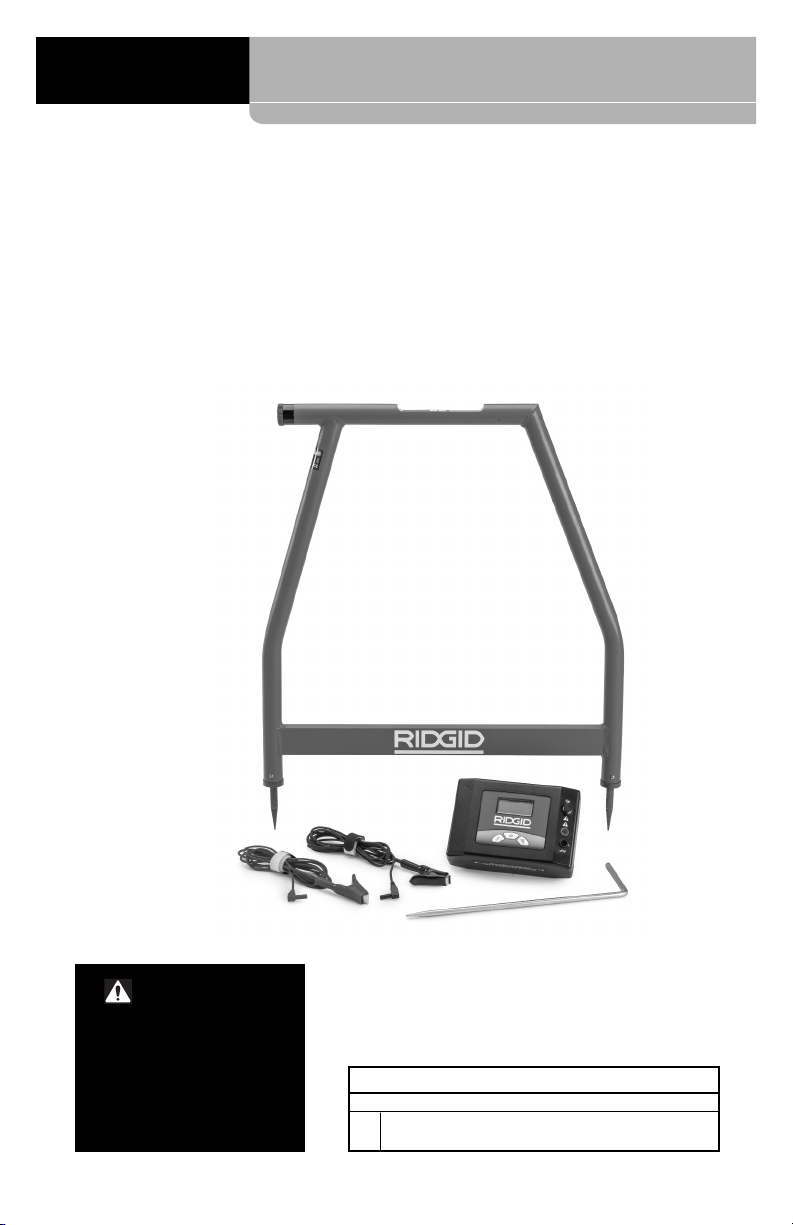
A-Frame Fault Locator
Model FT-103 Transmitter and
Model FR-30 Receiver
• Français – 15
• Castellano – pág. 33
Page 2

-Frame Fault Locator
A
Table of Contents
Recording Form for Machine Serial Number .....................................................................1
Safety Symbols.....................................................................................................................2
General Safety Rules
Work Area Safety...............................................................................................................2
Electrical Safety.................................................................................................................2
Personal Safety .................................................................................................................2
Equipment Use and Care ..................................................................................................2
Service ..............................................................................................................................3
Specific Safety Information
A-Frame Fault Locator Safety............................................................................................3
RIDGID Contact Information................................................................................................4
Description............................................................................................................................4
Transmitter.........................................................................................................................4
Receiver ............................................................................................................................5
Specifications.......................................................................................................................5
Standard Equipment..........................................................................................................6
Changing/Installing Batteries..............................................................................................6
Transmitter.........................................................................................................................7
Receiver (A-Frame) ...........................................................................................................7
Pre-Operation Inspection ....................................................................................................7
Set-Up And Operation Instructions ....................................................................................7
Fault Locating
Connecting Transmitter......................................................................................................8
Locating.............................................................................................................................9
Locating Below Paved Surfaces ......................................................................................10
Multiple Faults..................................................................................................................11
Path Locating
Direct Connect Path Locating Method .............................................................................11
Inductive Clamp Path Locating........................................................................................12
Broadcast Inductive Path Locating ..................................................................................12
Storage ................................................................................................................................13
Maintenance
Cleaning ..........................................................................................................................13
Calibration .......................................................................................................................13
Service And Repair..........................................................................................................13
Optional Equipment ...........................................................................................................14
Disposal ..............................................................................................................................14
Battery Disposal ..............................................................................................................14
EC Declaration of Conformity............................................................................................14
FCC Statement....................................................................................................................14
Electromagnetic Compatibility (EMC) ..............................................................................14
Lifetime Warranty.................................................................................................Back Cover
*Original Instructions - English
ii
999-995-095.10_REV. A
Page 3
A-Frame Fault Locator
A-Frame Fault Locator
Model FT-103 Transmitter and
Model FR-30 Receiver
WARNING!
Read this Operator’s Man ual
carefully before using this
tool. Failure to understand
and follow the contents of this
manual may result in electrical shock, fire and/or serious
person al injury.
A-Frame Fault Locator
Record Serial Number below and retain product serial number which is located on nameplate.
Serial
No.
Page 4
-Frame Fault Locator
A
Safety Symbols
In this operator’s manual and on the product, safety symbols and signal words are used to
communicate important safety information. This section is provided to improve understanding of these signal words and symbols.
his is the safety alert symbol. It is used to alert you to potential personal injury hazards.
T
bey all safety messages that follow this symbol to avoid possible injury or death.
O
DANGER
W
CAUTION
OTICE
N
ARNING
DANGER indicates a hazardous situation which, if not avoided, will result in death or
serious injury.
WARNING indicates a hazardous situation which, if not avoided, could result in
death or serious injury.
CAUTION indicates a hazardous situation which, if not avoided, could result in minor
or moderate injury.
NOTICE indicates information that relates to the protection of property.
This symbol means read the operator’s manual carefully before using the equipment. The operator’s manual contains important information on the safe and proper operation of the equipment.
This symbol means always wear safety glasses with side shields or goggles when handling
or using this equipment to reduce the risk of eye injury.
This symbol indicates the risk of electrical shock.
General Safety Rules
WARNING
Read all safety warnings and instructions. Failure to follow the warnings and
instructions may result in electric shock,
fire and/or serious injury.
SAVE ALL WARNINGS
AND INSTRUCTIONS FOR
FUTURE REFERENCE!
Work Area Safety
• Keep your work area clean and well lit.
Cluttered or dark areas invite accidents.
• Do not operate equipment in explosive
atmospheres, such as in the presence of
flammable liquids, gases or dust. E quip -
ment can create sparks which may ignite
the dust or fumes.
• Keep children and by-standers a way
while operating equipment. Distrac tions
can cause you to lose control.
Electrical Safety
• Avoid body contact with earthed or
ground ed surfaces such as pipes, radiators, ranges and refrigerators. There
is an increased risk of electrical shock if
your body is earthed or grounded.
• Do not expose equipment to rain or wet
conditions. Water en tering equipment will
increase the risk of electrical shock.
Personal Safety
• Stay alert, watch what you are doing
and use common sense when operating equipment. Do not use equipment
while you are tired or under the influence of drugs, alcohol or medication. A
moment of inattention while operating
equipment may result in serious personal
injury.
• Use personal protective equipment. Al -
ways wear eye protection. Protective equipment such as dust mask, non-skid safety
shoes, hard hat or hearing protection used
for appropriate conditions will reduce personal injuries.
• Do not overreach. Keep proper footing
and balance at all times. This enables
better control of the power tool in unexpected situations.
• Do not let familiarity gained from fre-
quent use of tools allow you to become
complacent and ignore tool safety principles. A careless action can cause severe
injury within a fraction of a second.
Equipment Use and Care
• Do not force equipment. Use the correct
equipment for your application. The cor-
2
999-995-095.10_REV. A
Page 5

ect equipment will do the job better and
r
safer at the rate for which it is designed.
• Do not use equipment if the switch does
not turn it ON and OFF. Any tool that cannot be controlled with the switch is dangerous and must be repaired.
• Remove the battery pack from the equip-
ment before making any adjustments,
changing accessories, or storing. Such
preventive safety measures reduce the risk
of injury.
• Store idle equipment out of the reach of
children and do not allow persons unfamiliar with the equipment or these instructions to operate the equipment.
Equipment can be dangerous in the hands
of untrained users.
• Maintain equipment. Check for missing
parts, breakage of parts and any other
condition that may affect the equipment’s
operation. If damaged, have the equipment repaired before use. Many accidents
are caused by poorly maintained equipment.
• Use the equipment and accessories in
accordance with these instructions,
taking into account the working conditions and the work to be performed.
Use of the equipment for operations different from those intended could result in a
hazardous situation.
• Keep handles and grasping surfaces
dry, clean and free from oil and grease.
Slippery handles and grasping surfaces
do not allow for safe handling and control of
the tool in unexpected situations.
Service
• Have your equipment serviced by a qual i fied repair person using on ly identical
replacement parts. This will ensure that the
safety of the tool is maintained.
Specific Safety
Information
WARNING
This section contains important safety information that is specific to this tool.
Read these precautions carefully before
using the RIDGID®A-Frame Fault Locator
to reduce the risk of electrical shock or
serious personal injury.
A-Frame Fault Locator
SAVE ALL WARNINGS
AND INSTRUCTIONS FOR
FUTURE REFERENCE!
Keep this manual with the tool for use by
the operator.
A-Frame Fault Locator Safety
• Do not expose the equipment to water
or rain. This increases the risk of electrical
shock.
• Do not operate the transmitter if opera-
tor or transmitter is standing in water.
Operating transmitter while in water increases the risk of electrical shock.
• Do not connect to live voltage or ac-
tive utility lines. Disconnect the conductor
to be tested from any other service, components, or anything that might be affected
by high voltage. De-energize any circuits in
or around the work area.
• Always attach transmitter test leads be-
fore turning unit ON and turn unit OFF
before disconnecting leads. This will re-
duce the risk of electrical shock.
• Never turn transmitter ON when anyone
is touching the conductor, ground stake,
or any part of the transmitter. Turn OFF
transmitter before touching test lead or any
un-insulated conductor.
• Do not use where a danger of high volt-
age contact is present. Do not attach
leads to high voltage conductors. The
equipment is not designed to provide high
voltage protection and isolation.
• Locating equipment uses electromag-
netic fields that can be distorted and interfered with. More than one utility may
be present in a given area. Follow local
guidelines and one call/call before you dig
service procedures. Exposing a utility is
the only way to verify its existence, location
and depth.
• Avoid traffic. Pay close attention to mov-
ing vehicles when using on or near
roadways. Wear visible clothing or reflec-
tor vests.
• Before operating the RIDGID A-Frame
Fault Locator, read and understand this
operator’s manual and the instructions
for any other equipment used. Failure to
follow all instructions and warnings may result in property damage and/or serious injury.
999-995-095.10_REV. A
3
Page 6
-Frame Fault Locator
A
Use this manual in conjunction with all
•
company, utility or facility procedures
and policies. Familiarize yourself with all
required procedures and policies, including
safety practices, prior to entering an area
and using the equipment.
NOTICE
Ridge Tool Company, its affiliates
and suppliers, will not be liable for any injury or
any direct, indirect, incidental or consequential
damages sustained or incurred by reason of
the use of the A-Frame Fault Locator.
RIDGID Contact
Information
If you have any question concerning this
®
RIDGID
product:
– Contact your local RIDGID distributor.
– Visit RIDGID.com to find your local
RIDGID contact point.
– Contact Ridge Tool Technical Service
De partment at rtctechservices@emer son.com, or in the U.S. and Canada call
(800) 519-3456.
Description
The RIDGID®A-Frame Fault Locator is a highly
sensitive transmitter and receiver specifically
designed to detect the location of a path to
ground fault (Direct Fault Finding (DFF)) in
the insulation of a buried conductor (such as a
wire or cable). Damaged insulation, severed
conductor, and other faults with ground leakage are easily and precisely located.
Model FT-103 Transmitter connects to the insulated conductor and establishes a current flow,
the current leaks to ground through the insulation fault and back to the ground stake. Model
FR-30 Receiver detects the current flow to
ground through the insulation fault. The receiver provides audio and visual indications of
both signal strength and direction to assist in
detecting and locating the fault. For the AFrame fault detector to work, the conductor
must be in contact with the earth – it will not
work with conductors in conduit.
Additionally, the transmitter can be used to
apply a signal to the conductor for path locating with other receivers, such as RIDGID
SeekTech
done by direct connect and inductive methods.
Multiple frequencies and power levels are provided.
®
or NaviTrack®Locators. This can be
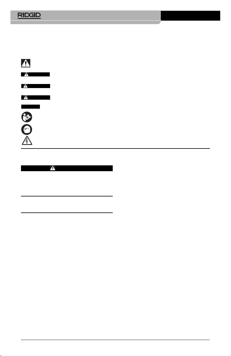
Receiver
Black Test Lead
(To Ground Stake)
Red Test Lead
To Conductor)
(
Figure 1 – A-Frame Fault Locator
ransmitter
T
Ground Stake
Transmitter
Transmitter Controls:
9
1
2
3
9
# Icon Description
1. — LCD Screen
2. ON/OFF and Inductive Mode Switch
Main Power Switch – Short press turns unit ON/OFF
Long press (5 seconds) enables Broadcast Inductive mode.
3. Frequency Selection
Selects the frequency of transmitter from preloaded frequencies. See Specifications for frequencies
4. — Serial and Warning Label (back of unit)
5. Inductive Clamp Jack
6. — Positive Terminal (to Conductor)
7. Negative Terminal (to Ground Stake)
8. Signal Power Setting
Depressing the Signal Power Button cycles the Signal
Power between Low, Medium and High
9. — Broadcast Inductive Decal (top and bottom)
Figure 2 – Transmitter Controls
4
5
6
7
8
4
999-995-095.10_REV. A
Page 7

A-Frame Fault Locator
ransmitter Display:
T
2
3
4
Number Icons Description
1–––kHz Frequency. “dFF” shown for fault finding.
2 Signal Power - # Of Bars On Increases with Increasing Power. Three Levels – Low, Medium
3
4 Voltage Warning – Transmitter connected to energized conductor – risk of electrical shock.
5 Transmitter Set for Fault Finding (dFF displayed in Frequency area (1)).
6 Transmitter Set for Inductive Clamp Use for Path Locating (Insert Inductive clamp into Jack)
7 Transmitter Set for Direct Connect Use for Fault Finding or Path Locating.
8 Transmitter Set for Broadcast Inductive Mode for Path Locating.
9 Transmitter Battery Status.
–––
and High.
Circuit Information, mA, V or Resistance in Ohms. Transmitter cycles through each at 2
second intervals.
Do not touch transmitter, leads or connections. Use high voltage precautions to disconnect.
1
5
6
7
8
9
Figure 3 – Transmitter Display
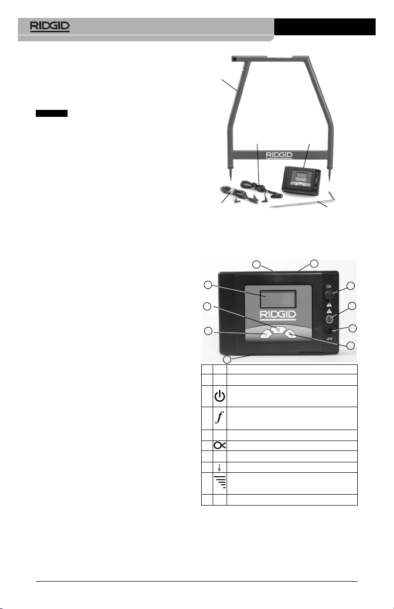
Receiver
Battery
Compartment
Serial Label
Display
Screen and
Controls
Receiver Controls/Display:
1
2
3
4
Warning
Label
Rear
Spike
Figure 4 – A Frame Receiver
999-995-095.10_REV. A
Front
Spike
5
# Icon Description
1 Reference Button
Ref
Stores and displays starting signal strength when pressed.
2 ON/OFF Button
Main Power Switch – Press to turn unit ON/OFF
3 Directional Arrow
Indicates direction of fault
4
Signal Strength
––
Displays absolute signal Strength from 0 to 99.
5 Low Battery Indicator
Figure 5 – Receiver Controls
Specifications
FT-103 Transmitter:
Operating
Frequencies .......Direct Fault Finding:
797 Hz - “dFF” displayed
5
Page 8

-Frame Fault Locator
A
Path locating:
128 Hz, 1 kHz, 8 kHz, 33
Hz, 93 kHz
k
Direct Connect:
128 Hz, 1 kHz, 8 kHz, 33
kHz, 93 kHz
Inductive Clamp:
8 kHz, 33 kHz, 93 kHz
Broadcast Inductive:
33 kHz, 93 kHz
Load Range .......5 Ω to 2M Ω
Output Power.....Up to 3 Watts (Low,
medium and high settings)
Output Voltage ...5 Volts - 600 Volts
Power Supply .....8 × C (R14) Cell
Batteries, 12 Volt
Battery Life.........Continuous: up to 15 hours,
Intermittent: up to 60 hours
(on low at 1000 Ohm load)
Operating
Temperature.......-4°F to 133°F
(-20°C to 55°C)
Storage
Temperature.......-13°F to 140°F
(-25°C to 60°C)
IP Rating ............IP54
Size....................8.5" x 5.8" x 2.5"
(21 cm x 15 cm x 6 cm)
Weight................2.2 lbs. (1 kg)
Test Lead
Jacks..................0.16" (4mm) as per
IEC61010
FR-30 A-Frame Receiver:
Operating
Frequencies .......Fault Finding:
797 Hz - “dFF” displayed
Direct Connect:
ower Supply.....6 × AA (LR6) Batteries,
P
9 Volt
Battery Life..........Continuous: up to 40 hours,
Intermittent: up to 82 hours
Operating
Temperature.......-4°F to 133°F
(-20°C to 55°C)
Storage
Temperature.......-13°F to 140°F
(-25°C to 60°C)
IP Rating ............IP54
Size....................30.3" x 30.4" x 1.5"
(77 cm x 77 cm x 4 cm)
Weight................3 lbs. (1.3 kg)
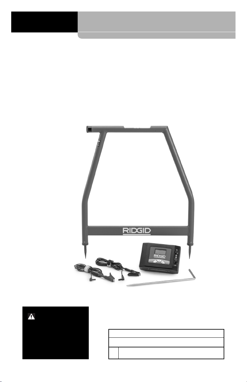
Standard Equipment
The A-Frame Fault Locator package includes
the following items:
• FR-30 A-Frame Receiver
• FT-103 Transmitter
• Ground Stake
• Red and Black Test Leads (7.5' (2.3 m) long)
• Carry Cases
• Batteries
• Operator’s Manual Pack
NOTICE
This equipment is used for conductor fault and path locating. Incorrect use or
improper application may result in incorrect or
inaccurate locating. Selection of appropriate locating methods for the conditions and proper
operation is the responsibility of the user.
Changing/Installing
Batteries
WARNING
Switch unit OFF and remove any connections from the Transmitter/Receiver
before changing batteries.
Fault Finding
Depth .................Up to 20' (6m) (depend-
ing on conditions)
Fault Finding
Length................Up to 3 miles (4800 m)
(depending on conditions)
Display ...............Black and White LCD
Audio
Indication ...........Piezo Response
6
The A-Frame Fault Locator is supplied without
the batteries installed. Remove the batteries
prior to storage to avoid battery leakage. When
the low battery indicator appears on the transmitter ( ) or receiver ( ) display, the batteries need to be replaced.
NOTICE
Use the batteries that are of same
type. Do not mix battery types. Do not mix
new and used batteries. Mixing batteries can
cause overheating and battery damage.
999-995-095.10_REV. A
Page 9

Transmitter:
1. With device OFF, remove the battery compartment cover. If needed, remove batteries (Figure 6).
Battery Compartment
+
-
+
-
+
-
Batteries
Figure 6 – Changing the Batteries (Transmitter)
+
-
Cover
2. Install eight new C Cell alkaline batteries
(R14), observing correct polarity as indicated in the battery compartment.
3. Securely reinstall the battery compartment cover.
Receiver (A-Frame):
1. With device OFF, unscrew the battery
com partment cover on the top tube (Fi -
gure 7). If needed, remove batteries.
Battery
Compartment Cover
A-Frame Fault Locator
ault Locator and correct any problems
F
to reduce the risk of serious injury from
electric shock and other causes, and
prevent equipment damage.
1. Make sure the transmitter and receiver
units are OFF.
2. Remove the batteries and inspect for
signs of damage. Replace if necessary.
Do not use if the batteries are damaged.
3. Clean the equipment. This aids inspection
and helps prevent the tool from slipping
from your grip.
4. Inspect the locator for the following:
• Proper assembly, maintenance and com -
pleteness.
• Any broken, worn or missing parts.
• Inspect the transmitter test leads for
damaged insulation or exposed wire.
• Presence and readability of the transmit-
ter and receiver warning labels (Figure
2 and 4).
• Any other condition which may prevent
safe and normal operation.
If any problems are found, do not use
the A-Frame Fault Locator until the problems have been repaired.
5. Inspect and maintain any other equipment being used per its instructions to
make sure it is functioning properly.
Figure 7 – Changing the Batteries (Receiver)
Batteries
2. Install six new AA alkaline batteries (LR6),
observing correct polarity as indicated
in the battery compartment.
3. Securely reinstall the battery compartment cover.
Pre-Operation Inspection
WARNING
Daily before use, inspect your A-Frame
999-995-095.10_REV. A
Set-Up And Operation
Instructions
WARNING
Do not connect to live voltage or active
utility lines. Disconnect the conductor
to be tested from any other service, components, or anything that might be affected by high voltage. De-energize any
circuits in or around the work area.
Always attach transmitter test leads before turning unit ON and turn unit OFF before disconnecting leads. This will reduce the risk of electrical shock.
Never turn transmitter ON the unit when
anyone is touching the conductor, ground
stake, or any part of the transmitter. Turn
7
Page 10

-Frame Fault Locator
A
OFF transmitter before touching test lead
or any un-insulated conductor.
o not use where a danger of high volt-
D
ge contact is present. Do not attach
a
leads to high voltage conductors. The
quipment is not designed to provide
e
high voltage protection and isolation.
ocating equipment uses electromag-
L
netic fields that can be distorted and interfered with. More than one utility may
be present in a given area. Follow local
guidelines and one call/call before you dig
service procedures. Exposing a utility is
the only way to verify its existence, location and depth.
Follow set up and operating instructions
to reduce the risk of injury from electrical
shock and other causes and to prevent
tool damage
Model FT-103 Transmitter and Model FR-30
Receiver are used for fault locating of conductors through direct connect method.
The Model FT-103 Transmitter only can be
used for path locating with RIDGID SeekTech
and NaviTrack®Locators. This can be done by
direct connect and inductive methods.
1. Confirm have appropriate work area (See
General Safety Rules). Operate in clear,
level, stable, dry location.Do not use transmitter while standing in water.
2. Determine the correct equipment for the
application, see Description and Specifi -
cations sections.
3. Make sure all equipment has been inspected and set up as directed in their instructions.
Fault Locating
It is good practice to locate the conductor path
before attempting to fault locate. This can be
done using a variety of RIDGID locating equipment. If during the location of the conductor
path an unusual amount of signal loss occurs,
this may give some indication of the conductor
insulation fault location. Additionally, use visual
cues and past history to aid in identifying the
conductor path and potential fault locations.
Once the conductor path is determined, the
RIDGID FT-103 Transmitter and FR-30 A-Frame
Receiver can be used to locate ground faults in
the insulated conductor. The Model FT-103
Transmitter connects to the insulated conductor
and establishes a current flow, the current
leaks to ground through the insulation fault
and back to the ground stake. The Model FR-30
Receiver detects the current flow to ground
hrough the insulation fault. For the A-Frame
t
fault detector to work, the conductor must be in
contact with the earth – it will not work with conductors in conduit. Generally, the A-Frame Fault
Locator works best in earth. Use with gravel,
asphalt, concrete or other ground covers may
not work as well.
The signal strength at the fault depends on
the amount of current leaking there. The greater
the leakage, the greater the signal strength.
Connecting Transmitter
1. Disconnect all loads and grounds from
the conductor to be tested and all neighboring conductors to prevent damage from
high voltage and false reading. Both ends
should be known and disconnected. Dis connecting both ends of the conductor
forces all of the transmitter signal through
the fault, improving the fault locate.
2. Insert supplied ground stake into the earth.
®
Ideally, the ground stake should be in line
with the conductor, 3' to 6' (1m to 2m)
from the end. If conditions require, the
ground stake can be placed to the side of
the conductor. Do not to place the ground
stake over the conductor. It is not recommended to use other existing grounds,
existing grounds may result in signal being
inadvertently applied to non-target cables.
A good ground results in a stronger tracing
signal. To get a good ground, insert the
ground stake as far as possible into the
earth. Moist earth will give a better ground
than dry earth. Wetting the earth around
the ground stake can improve grounding.
This lowers the resistance of the circuit.
While moist earth around the ground stake
improves the circuit, do not use the transmitter in areas that are wet, this can increase the risk of electrical shock.
3. Make sure that the transmitter is OFF.
4. Connect BLACK test lead to the ground
stake. Always connect to the ground stake
first.
5. Connect the BLACK and RED test leads
to the Transmitter.
6. Connect the RED test lead to the conductor to be tested (see Figure 9).
8
999-995-095.10_REV. A
Page 11

Transmitter
A-Frame Fault Locator
Red
Black
Ground Rod
3" – 6"
1 – 2 m)
(
Figure 8 – Transmitter Connections for Fault Locating
Buried Conductor
Locating
1. Make sure that no one is near or touching
the conductor, transmitter, leads or ground
stake. Press the ON/OFF button on the
eceiver
R
eturn Path
R
Through Soil
THE TRANSMITTER, LEADS OR CONNECTIONS. The target conductor is energized and
there is the risk of electrical shock. Use high
voltage precautions to disconnect.
transmitter to turn the transmitter ON.
When the transmitter is turned on, it is set
to the last used frequency. If needed,
press the frequency button on the transmitter until “dFF” is shown on screen
(Figure 9).
arth
E
Fault
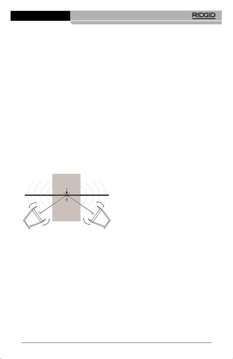
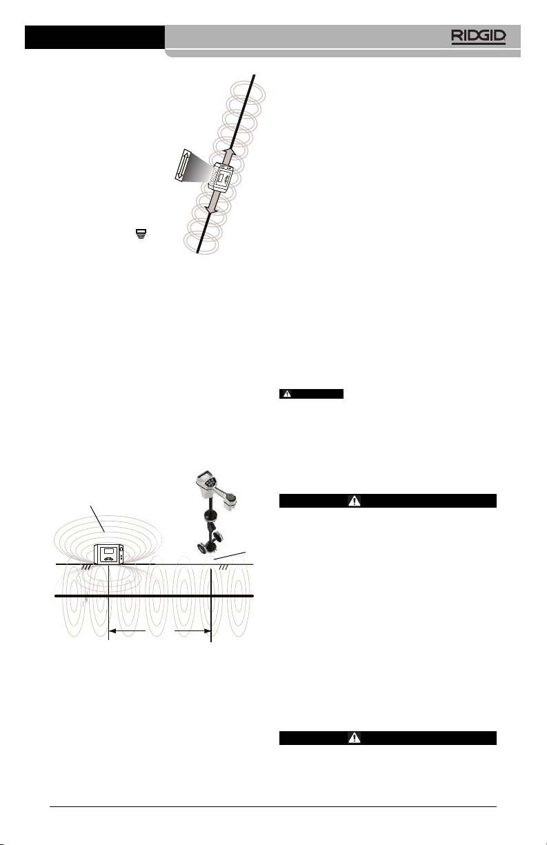
2. When fault locating, generally the receiver
should be used over the conductor, with
the front receiver spike towards the expected fault and the rear receiver spike towards the ground stake. The receiver
spikes should evenly penetrate the earth
to make good electrical contact. The current flowing in and out of the ground
spikes supplies the signal to locate the insulation fault (see Figure 10).
Figure 9 – Transmitter Screen
Adjust the signal power by pressing the signal
power button to cycle through the settings (low,
medium and high). Using high power may result in signal going to ground at non-target
points, low power may mean a circuit is not created. The transmitter will display circuit resistance (OHMS) at the bottom of the LCD. The
lower the resistance the better the locate signal.
To improve the circuit, improve the ground,
check the lead connections or increase the
power.
The transmitter will continuously beep when
there is a circuit. The lower the circuit resistance, the quicker the beep. The transmitter
will beep three times and a pause (repeating) if there is no circuit.
If the transmitter display shows voltage warning (Figure 3), the transmitter is connected to
live voltage. If this happens, DO NOT TOUCH
999-995-095.10_REV. A
Conductor (End View)
Figure 10 – Receiver Positioning
Conductor (Side View)
3. To start the locate, place the A-Frame
receiver between the ground stake and
the transmitter connection to the conductor. Press the A-Frame Receiver ON/OFF
button to turn receiver ON.
The signal strength will appear on the
receiver display. Signal strength will be the
highest near the ground stake and at
faults. Press the “Ref” button to store a reference signal strength near the ground
stake.
The receiver display arrows will indicate
the direction of the fault. Fault direction is
also indicated audibly - a long slow beep
indicates forward direction and a quick
beep indicates backward direction.
9
Page 12

-Frame Fault Locator
A
4. Remove the receiver from the earth and
move several steps as indicated by the
irectional arrow and beeping along the
d
conductor path. Reinsert the receiver
spikes into the earth (Figure 11).
Continue moving away from the ground
stake along the conductor path. Signal
strength should drop (in some cases going
to zero) and then rise as you move towards a fault.
5. Signal strength will peak over the fault. If
you pass the fault, the directional arrow will
change direction and the beep will change
from long slow to quick beep and the signal strength will decrease. Continue to
move the receiver back and forth until
slight movement causes the directional
arrows and beeping to toggle back and
forth. At this point, the fault is centered between the spikes of the receiver.
Compare the signal strength to the reference signal strength taken near the
ground stake. They should be similar. If the
fault signal strength is much lower than the
reference value, you may not have located a fault. For instance, a grounded
splice point would behave as a fault during
the locate, but would give a much lower
signal strength. For a low fault signal
strength, you may want to mark the location and continue down the conductor
ath looking for a fault signal strength
p
closer to the reference signal.
Once a fault is located with a signal similar
to the reference signal, turn the A-Frame
Locator perpendicular to the path of the
conductor. Move the receiver back and
forth until slight movement causes the directional arrows and beeping to toggle
back and forth. At this point, the fault is
centered between the spikes of the receiver. See Figure 12. Mark the location of
the fault.
6. Once the locating is completed, press the
ON/OFF button to turn the transmitter OFF.
Always turn the unit OFF before disconnecting the cable leads to reduce the risk
of electrical shock. Remove the cable lead
from the target conductor first. Always disconnect the cable lead from the target
conductor first before removing the cable
lead from the ground spike to reduce the
risk of electrical shock. Disconnect the
cable lead from the ground spike.
Locating Below Paved
Surfaces
Locating can be difficult if the fault is below a
paved surface, because the receiver spikes
cannot make good electrical contact with
the earth. In this case, there are several
methods that can be used.
Ground Rod
Figure 11 – Signal Strength
Fault
Figure 12 – Final Locate
10
Conductor (End View)
Fault
Conductor (Side View)
Fault
Signal Strength
Signal
Strength
999-995-095.10_REV. A
Page 13
If the paved area is relatively small, the
•
receiver can be used around the periphery
of the area. The receiver can be rotated
side to side, and where the receiver directional arrows and beeping toggle back
and forth, extend a straight line perpendicular to the center of the A-Frame Receiver.
Do this in several locations around the
suspected fault area. The straight lines
should all intersect at the same point. This
is the location of the fault. This method of
locating is less exact than placing the receiver directly over the conductor. See
Figure 13.
• An alternate way to locate below paved
surfaces is to improve the conductivity between the pavement and the receiver with
water. One method is to attach sponges to
the spikes of the receiver. Wet the sponges
with water and keep wet. Conduct the fault
locate normally.
• Another method is to wet the surface of the
pavement with water and conduct the fault
locate normally. Do not do this in the area
of the transmitter – this increases the risk of
electrical shock.
Paved Area
Conductor
Fault
Figure 13 – Locating below paved surfaces
Multiple Faults
If there are multiple faults in the conductor,
the faults will have signals proportional to
the amount of current leaking. The locate is
done the same as for a single fault, but the
signal strength will not be as strong. Typically,
the largest fault (least resistance fault) is
easiest to find. Best practice is to find and repair the first fault and continue the locate
for other faults.
Path Locating
The FT-103 Transmitter can be used with other
commercially available receivers (such as the
RIDGID SeekTech or NaviTrack receivers) to
path locate conductors. The FT-103 transmitter
A-Frame Fault Locator
an be used to apply an active tracing signal to
c
a conductor in three ways:
• Direct Connect – The transmitter’s leads
are connected directly to the target conductor and a suitable ground. This method is
most commonly used when the target utility is accessible. Direct connect should not
be used for energized (live) conductors.
• Inductive Clamp (optional equipment) –
the jaws of the inductive clamp encircle
the target conductor; if the conductor is insulated, there is no metal to metal contact.
This method is commonly used when the
target utility is accessible but direct connect is not possible on an insulated cable.
• Broadcast Inductive Mode – The transmitter generates a field, which in turn induces
a current in the target conductor. There is no
direct connection between the transmitter
and the target conductor. The transmitter is
placed over and inline with the target conductor. The transmitter’s internal antenna induces a signal onto the target conductor.
This method is most commonly used when
the target utility is not accessible.
Disconnect all loads from the conductor to
be tested and all neighboring conductors to
prevent damage from high voltage and false
reading.
Direct Connect Path Locating
Method
1. Insert supplied ground stake into the
earth. Or, if other good grounds are available in the area, they can be used.
A good ground results in a stronger tracing
signal. To get a good ground, insert the
ground stake as far as possible into the
earth. Moist earth will give a better ground
than dry earth. Wetting the earth around
the ground stake can improve grounding.
This lowers the resistance of the circuit.
While moist earth around the ground
stake improves the circuit, do not use the
transmitter in areas that are wet, this can
increase the risk of electrical shock.
The far end of the conductor should be
grounded.
2. Make sure that the transmitter is OFF.
3. Connect BLACK test lead to the ground
stake. Always connect to the ground stake
first.
4. Connect the BLACK and RED test leads
to the Transmitter.
999-995-095.10_REV. A
11
Page 14

-Frame Fault Locator
A
. Connect the RED test lead to the conduc-
5
tor to be tested.
6. Press the ON/OFF button to turn the transmitter ON. When the transmitter is turned
on, it is set to the last used frequency.
Press the frequency selection button to
cycle through frequency settings to the
desired locating frequency.
Adjust the signal power by pressing the
signal power button to cycle through the
settings (low, medium and high). Using
high power can couple into non-target
conductors, low power may mean a circuit
is not created. The transmitter will display
circuit resistance (OHMS) at the bottom of
the LCD. The lower the resistance the better the locate signal. To improve the circuit,
improve the ground, check the lead connections, increase power or change the
frequency.
If the transmitter display shows voltage
warning (Figure 3), the transmitter is con-
nected to live voltage. If this happens,
DO NOT TOUCH THE TRANSMITTER,
LEADS OR CONNECTIONS. The tar-
get conductor is energized and there is
the risk of electrical shock. Use high voltage precautions to disconnect.
7. Check the circuit and adjust signal power,
grounding or connections to ensure locatable field.
8. Turn ON the receiver/locator and follow
the instructions for the receiver. Make sure
the receiver’s frequency is set to match that
on the transmitter. Confirm the receiver is
picking up the transmitted frequency by
holding it near the transmitter and observing the increase in receiver signal.
9. Once the locating is completed, press the
ON/OFF button to turn the transmitter
OFF. Always turn the unit OFF before disconnecting the cable leads to reduce the
risk of electrical shock. Remove the cable
lead from the target conductor first. Always
disconnect the cable lead from the target
conductor first before removing the cable
lead from the ground spike to reduce the
risk of electrical shock. Disconnect the
cable lead from the ground spike.
all instruction for the use of the inductive
clamp.
2. Insert the plug of the inductive clamp
into transmitter (see Figure 2).
3. Clamp the jaws of the inductive clamp
around the target conductor. Make sure
that the jaws of the clamp are fully closed.
(See Figure 14). Both ends of the conductor should be grounded for best results.
Figure 14 – Inductive Clamp Attached to a
Conductor
4. Press the ON/OFF button to turn the trans mitter ON. When the clamp is plugged in
the clamp symbol ( ) shows on the
screen and only clamp frequencies are
available. Press the frequency selection
button to cycle through frequency settings
to the desired locating frequency. Adjust
the signal power by pressing the signal
power button to cycle through the settings
(low, medium and high). The inductive
clamp typically works best with frequencies around 8kHz, 33 kHz, 93kHz.
5. Check the circuit and adjust signal strength
(see Figure 3, Circuit Information).
6. Turn ON the receiver/locator and follow
the instructions for the receiver. Make
sure the receiver’s frequency is set to
match that on the transmitter. Confirm
the receiver is picking up the transmitted
frequency by holding it near the transmitter and observing the increase in receiver signal.
7. Once the locating is completed, press
the ON/OFF button to turn the transmitter
OFF.
Inductive Clamp Path
Locating
1. This method requires an inductive clamp
(Optional equipment). Read and follow
12
Broadcast Inductive Path
Locating
1. Properly place the transmitter relative to
the target conductor (see Figure 15). On
the top of the transmitter is an arrow. Set
999-995-095.10_REV. A
Page 15
ransmitter on ground,
t
align arrow with the
target conductor.
Conductor
2. Press the ON/OFF
button to turn the
trans mitter ON. Press
and hold the power
button for 5 seconds
selection button to
shift transmitter into
broadcast inductive
mode. Broadcast inductive icon ( ) appears on screen and
the transmitter will
start beeping to indicate that it is operating.
Figure 15 –
Orientation to the
Line – Inductive
Mode
Adjust the signal power by pressing the
signal power button to cycle through the
settings (low, medium and high) and
choose high. Press the frequency selection button to cycle through 33khz and
93kHz frequency settings to the desired
locating frequency. When using Broadcast
Inductive Mode, higher frequencies tend
to get a better signal at the receiver.
3. Turn ON the locator and follow its instructions. Make sure to set the receiver to
the same frequency as the transmitter.
A-Frame Fault Locator
uctor. This is called “Air Coup ling”. Operate
d
the receiver at least 30 feet from the transmitter to prevent this. (See Figure 16).
One way to confirm that you are tracing the
target conductor and not the transmitter
field is to look for a strong, stable prox imity
signal and a valid depth measurement on
the receiver. While directly over the energized line you can also raise the receiver a
set distance off of the ground, and verify
that the depth reading on the display e quals the distance that you raised the receiver.
4. Once the locating is completed, press the
Power ON/OFF button for 5 seconds to
exit broadcast inductive mode, then press
the ON/OFF button to turn the transmitter
OFF.
Storage
Remove batteries from tool. Store the A-Frame
Fault Locator in case. Avoid storing in extreme heat or cold.
WARNING
area that is out of reach of children and
people unfamiliar with the RIDGID A-Frame
Fault Locator. The locator is dangerous in
the hands of untrained users.
Store tool in a dry, secured
Transmitter Field
Induced
Field on
Target
Conductor
Conductor
30 feet
Minimum
Figure 16 – Orientation to the Line – Inductive
Mode
When the transmitter is in broadcast inductive mode, it generates a field around the
transmitter. This field is in both the ground
(towards the target conductor) and into
the air around the transmitter. When the receiver is within approximately 30 feet (10
meters) of the transmitter, it will measure
the field directly from the transmitter and
not the signal induced on the target con-
999-995-095.10_REV. A
Maintenance
WARNING
Remove batteries from tool before performing maintenance or making any
adjustment.
Cleaning
Do not immerse the A-Frame Fault Locator in
water. Wipe off dirt with a damp soft cloth.
Avoid rubbing too hard. Do not use aggressive
cleaning agents or solutions.
Calibration
The A-Frame Fault Locator is factory calibrated and only requires recalibration if repaired.
Service And Repair
WARNING
Improper ser vice or repair can make
the machine unsafe to operate.
Service and repair on this A-Frame Fault Lo -
13
Page 16

-Frame Fault Locator
A
ator must be performed by a RIDGID Inde -
c
pendent Service Center. Use only RIDGID
service parts.
For information on your nearest RIDGID Inde pen dent Service Center or any service or repair
questions, see Contact Information Section in
this manual.
Optional Equipment
WARNING
To reduce the risk of injury, only use accessories specifically designed and recommended for use with the RIDGID AFrame Fault Locator, such as listed below.
Catalog
No. Description
20973 RIDGID SeekTech 4" (100 mm)
57763 Ground Stake, FT-103
57768 Red and Black Test Leads, FT-103
96967 RIDGID NaviTrack II Locator
19238 RIDGID NaviTrack Scout Locator
22163 RIDGID SeekTech SR-60 Line Locator
21893 RIDGID SeekTech SR-20 Line Locator
44473 RIDGID SR-24 Line Locator with
For a complete listing of RIDGID equipment
avail able for this tool, see the Ridge Tool Cata log online at RIDGID.com or see Contact
Information.
Inductive Signal Clamp
®
Bluetooth
and GPS
Disposal
Parts of this tool contain valuable materials
and can be recycled. There are companies
that specialize in recycling that may be found
locally. Dispose of the components in compliance with all applicable regulations. Contact
your local waste management authority for
more information.
For EC Countries: Do not dispose
of elec trical equipment with household waste!
According to the European Guide line 2012/ 19/EU for Waste Elec trical
imple men tation into national legislation, electrical equipment that is no longer usable must
be collected separately and disposed of in
an environmentally correct manner.
and Electronic Equipment and its
Battery Disposal
For EC countries: Batteries must be recycled
according to the guideline 2006/66/EEC.
EC Declaration of
Conformity
The EC Declaration of Conformity (890-011-
320.10) will accompany this manual as a separate booklet when required.
FCC Statement
This equipment has been found to comply
with the limits for a Class B digital device,
pursuant to part 15 of the FCC Rules. These
limits are designed to provide reasonable protection against harmful interference in a residential installation.
This equipment generates, uses, and can radiate radio frequency energy and, if not installed and used in accordance with the instructions, may cause harmful interference
to radio communications.
However, there is no guarantee that interference will not occur in a particular installation.
If this equipment does cause harmful interference to radio or television reception, which can
be determined by turning the equipment OFF
and ON, the user is encouraged to try to correct the interference by one or more of the following measures:
• Reorient or relocate the receiving antenna.
• Increase the separation between the equipment and receiver.
• Consult the dealer or an experienced radio/ TV technician for help.
Electromagnetic
Compatibility (EMC)
The term electromagnetic compatibility is taken
to mean the capability of the product to function
smoothly in an environment where electromagnetic radiation and electrostatic discharges
are present and without causing electromagnet
interference to other equipment.
NOTICE
conform to all applicable EMC standards.
However, the possibility of it causing interference in other devices cannot be precluded. All
EMC related standards that have been tested
are called out in the tool’s technical document.
The RIDGID A-Frame Fault Locator
14
999-995-095.10_REV. A
Page 17
Localisateur de rupture A-Frame
Localisateur de rupture A-Frame
Transmetteur FT-103 et
Récepteur FR-30
AVERTISSEMENT
Familiarisez-vous avec le présent
mode d’emploi avant d’utiliser l’appareil. Tout manque de compréhension ou de respect des consignes ciaprès augmenterait les risques de
choc électrique, d’incendie et/ou d’accident grave.
Localisateur de rupture A-Frame
Pour future référence, notez ci-dessous le numéro de série de l’appareil qui apparait sur sa
plaque signalétique.
No de
série
Page 18

ocalisateur de rupture A-Frame
L
Table des matières
Fiche d’enregistrement du numéro de série de l’appareil..............................................15
Symboles de sécurité.........................................................................................................17
Consignes générales de sécurité
Sécurité des lieux ............................................................................................................17
Sécurité électrique...........................................................................................................17
Sécurité individuelle.........................................................................................................17
Utilisation et entretien du matériel ...................................................................................18
Service après-vente.........................................................................................................18
Consignes de sécurité spécifiques
Sécurité du localisateur de rupture..................................................................................18
Coordonnées RIDGID.........................................................................................................19
Description..........................................................................................................................19
Transmetteur....................................................................................................................20
Récepteur........................................................................................................................21
Caractéristiques techniques .............................................................................................22
Equipements de base......................................................................................................22
Remplacement des piles ...................................................................................................23
Transmetteur....................................................................................................................23
Récepteur A-Frame .........................................................................................................23
Inspection préalable...........................................................................................................23
Préparation et utilisation de l’appareil .............................................................................24
Localisation de rupture
Connexion du transmetteur .............................................................................................25
Localisation .....................................................................................................................25
Localisation sous chaussée ............................................................................................27
Ruptures multiples...........................................................................................................28
Traçage des conducteurs
Traçage par connexion directe.........................................................................................28
Traçage par pince à induction .........................................................................................29
Traçage par transmission inductive .................................................................................30
Stockage .............................................................................................................................30
Entretien
Nettoyage ........................................................................................................................31
Calibrage .........................................................................................................................31
Révisions et réparations..................................................................................................31
Accessoires ........................................................................................................................31
Recyclage............................................................................................................................31
Recyclage des piles.........................................................................................................32
Déclaration de conformité CE ...........................................................................................32
Enoncé FCC........................................................................................................................32
Compatibilité électromagnétique (EMC) ..........................................................................32
Garantie à vie...................................................................................................page de garde
*Traduction de la notice originale
16
999-995-095.10_REV. A
Page 19

Localisateur de rupture A-Frame
Symboles de sécurité
Les symboles et mots clés utilisés à la fois dans ce mode d’emploi et sur l’appareil lui-même
servent à signaler d’importants risques de sécurité. Ce qui suit permettra de mieux comprendre la signification de ces mots clés et symboles..
Ce symbole sert à vous avertir de risques d’accident potentiels. Le respect des consignes qui le
suivent vous permettra d’éviter les risques d’accident grave ou potentiellement mortel.
e terme DANGER signifie une situation dangereuse qui, faute d’être évitée, provo-
DANGER
AVERTISSEMENT
TTENTION
A
VIS IMPORTANT
A
L
querait la mort ou de graves blessures corporelles.
Le terme AVERTISSEMENT signifie une situation dangereuse potentielle qui,
faute d’être évitée, serait susceptible d’entraîner la mort ou de graves blessures
corporelles.
Le terme ATTENTION signifie une situation dangereuse potentielle qui, faute d’être
évitée, serait susceptible d’entraîner des blessures corporelles légères ou modérées.
Le terme AVIS IMPORTANT indique des informations concernant la protection
des biens.
Ce symbole indique la nécessité de bien se familiariser avec la notice d’emploi avant d’utiliser ce
matériel. La notice d’emploi renferme d’importantes consignes de sécurité et d’utilisation du
matériel.
Ce symbole impose le port systématique de lunettes de sécurité à œillères lors de la manipulation ou utilisation de ce matériel afin de limiter les risques de lésion oculaire.
Ce symbole indique un risque de choc électrique.
Consignes générales de
sécurité
AVERTISSEMENT
Familiarisez-vous avec l’ensemble des
consignes de sécurité et d’utilisation. Le
non-respect des consignes ci-après augmenterait les risques de choc électrique,
d’incendie et/ou d’accident grave.
Conservez l’ensemble des consignes
de sécurité et d’utilisation pour
future référence !
Sécurité des lieux
• Assurez-vous de la propreté et du bon
éclairage des lieux. Les chantiers en-
combrés ou mal éclairés sont une invitation
aux accidents.
• N’utilisez pas d’appareils électriques en
présence de substances volatiles telles
que liquides, gaz ou poussières combustibles. Ce type de matériel risque de
produire des étincelles susceptibles d’enflammer les poussières et émanations combustibles.
• Eloignez les enfants et les curieux durant
l’utilisation des appareils électriques.
Les distractions risquent de vous faire perdre le contrôle de l’appareil.
Sécurité électrique
• Evitez tout contact avec des objets reliés
à la terre tels que canalisations, radiateurs, cuisinières et réfrigérateurs. Tout
contact avec la terre augmenterait les
risques de choc électrique.
• N’exposez pas l’appareil à la pluie ou
aux intempéries.Toute pénétration d’eau à
l’intérieur d’un appareil électrique augmenterait les risques de choc électrique.
Sécurité individuelle
• Soyez attentif, restez concentré et faites
preuve de bon sens lors de l’utilisation
de ce type d’appareil. Ne jamais utiliser
ce matériel lorsque vous êtes fatigué ou
sous l’influence de drogues, de l’alcool
ou de médicaments. Lors de l’utilisation
d’un appareil électrique, un instant d’inattention risque d’entraîner de graves lésions corporelles.
• Prévoyez les équipements de protec-
tion individuelle appropriés. Portez systématiquement une protection oculaire.
Selon le cas, le port d’un masque à poussière, de chaussures de sécurité antidérapantes, du casque ou d’une protection auriculaire peut aider à limiter les risques
d’accident grave.
999-995-095.10_REV. A
17
Page 20

ocalisateur de rupture A-Frame
L
• Ne vous mettez pas en porte-à-faux.
aintenez une bonne assiette et un bon
M
équilibre à tout moment. Cela assurera
un meilleur contrôle de l’appareil en cas
d’imprévu.
• Ne laissez pas la familiarité issue d’une
utilisation fréquente des appareils vous
rendre complaisant au point d’ignorer
les principes de sécurité applicables.
Le moindre faux pas peut occasionner de
graves blessures en une fraction de seconde.
Utilisation et entretien de
l’appareil
• Ne forcez pas l’appareil. Prévoyez l’ap-
pareil le mieux adapté aux travaux envisagés. Un appareil adapté produira de
meilleurs résultats et un meilleur niveau
de sécurité lorsqu’il fonctionne au régime
prévu.
• N’utilisez pas d’appareil dont l’interrup-
teur marche/arrêt ne fonctionne pas correctement. Tout appareil qui ne peut pas
être contrôlé par son interrupteur est considéré dangereux et doit être réparé.
• Retirez le bloc-piles de l’appareil avant
tout réglage, remplacement d’outils ou
stockage. De telles mesures préventives
aideront à limiter les risques d’accident.
• Rangez tout appareil non utilisé hors
de la portée des enfants et ne permettez
à aucun individu non familier avec ce
matériel ou les instructions ci-présentes
d’utiliser le matériel. Ce type d’appareil
peut devenir dangereux entre les mains
d’un novice.
• Assurez l’entretien approprié de l’ap-
pareil. Assurez-vous de l’absence d’éléments grippés ou endommagés, voire toute
autre anomalie susceptible de nuire au bon
fonctionnement et à la sécurité de l’appareil. Ne jamais utiliser d’appareil endommage avant sa réparation. De nombreux
accidents sont le résultat d’appareils mal entretenus.
• Utilisez l’appareil et ses accessoires se-
lon les consignes ci-présentes, tout en
tenant compte des conditions d’intervention et du type de travail envisagé.
L’emploi de ce matériel à des fins autres
que celles prévues pourrait entrainer une
situation dangereuse.
Maintenez les poignées et autres sur-
•
faces de prise en main de l’appareil
dans un parfait état de propreté. Cela
assurera une meilleure prise en main du
matériel.
Service après-vente
• Confiez la révision de l’appareil à un réparateur qualifié se servant exclusivement de pièces de rechange identiques
aux pièces d’origine. Cela assurera la
sécurité opérationnelle de l’appareil.
Consignes de sécurité
spécifiques
AVERTISSEMENT
La section suivante contient d’importantes consignes de sécurité visant ce
localisateur en particulier.
Afin de limiter les risques de choc électrique ou autre accident grave, familiarisez-vous avec les consignes suivantes
avant d’utiliser le localisateur de rupture
A-Frame.
Conservez l’ensemble des consignes
de sécurité et d’utilisation pour
future référence !
Gardez ce mode d’emploi avec l’appareil
afin qu’il soit à portée de main de tout utilisateur éventuel.
Sécurité du localisateur de
rupture A-Frame
• N’exposez pas ce matériel à l’eau ou
aux intempéries. Cela augmenterait les
risques de choc électrique.
• N’utilisez pas le transmetteur lorsque
l’opérateur ou le transmetteur a les pieds
dans l’eau. L’utilisation du transmetteur en
présence d’eau augmenterait les risques de
choc électrique.
• Ne connectez pas ce matériel à un objet
sous tension ou à des lignes électriques.
Déconnectez le conducteur à contrôler de
tout service, composant ou autre élément
qui risque d’être sous haute tension. Coupez
le courant à tout circuit électrique sur le
chantier ou dans ses environs.
18
999-995-095.10_REV. A
Page 21

Localisateur de rupture A-Frame
• Il faut toujours connecter les câbles du
ransmetteur avant de l’allumer, puis
t
éteindre le transmetteur avant de les déconnecter. Cela limitera les risques de
choc électrique.
• Ne jamais allumer le transmetteur lorsque
quelqu’un touche le conducteur, le piquet de terre ou toute autre partie du
transmetteur. Eteignez le transmetteur avant
de toucher ses câbles ou tout conducteur
non isolé.
• N’utilisez pas ce matériel là ou il y a
risque d’entrer en contact avec des éléments sous haute tension. Ne jamais
connecter les câbles à des conducteurs
sous haute tension. Ce matériel n’offre
aucune protection ou isolation contre les
éléments sous haute tension.
• Ce matériel de localisation utilise des
champs magnétiques qui sont susceptibles aux déformations et au parasitage.
Il risque d’y avoir plusieurs circuits électriques dans les environs. Respectez les
consignes locales et contactez les services concer nés avant de creuser. Le
sondage d’un service souterrain est le seul
moyen de vérifier son existence, sa position
et sa profondeur.
• Evitez la circulation routière. Faites par-
ticulièrement attention à la circulation
des véhicules lorsque vous travaillez
sur ou à proximité de la chaussée. Portez
des vêtements visibles ou des vestes
réfléchissantes.
• Avant d’utiliser le localisateur de rupture
RIDGID A-Frame, familiarisez-vous avec le
mode d’emploi ci-présent et ceux de tout
autre matériel utilisé. Le non-respect de
l’ensemble des consignes et avertissement
qu’ils renferment pourrait occasionner des
dégâts matériels et/ou de graves blessures
corporelles.
• Utilisez ce manuel en conjonction avec
l’ensemble des procédés et règles établis par votre entreprise, les services
publics ou les lieux d’intervention. Fami-
liarisez-vous avec l’ensemble des consignes
d’intervention, et notamment les consignes
de sécurité, avant de pénétrer les lieux et d’utiliser ce matériel.
AVIS IMPORTANT
i la société Ridge Tool
N
Company, ses filiales ou ses fournisseurs ne
sauraient être tenu responsables de blessures
ou dégâts directs, indirects, fortuits ou consécutifs subis en raison de l’utilisation du localisateur de rupture A-Frame.
Coordonnées RIDGID
En cas de questions concernant ce produit
®
RIDGID
veuillez :
– Consulter le distributeur RIDGID le plus
proche ;
– Visiter le site www.RIDGID.com pour lo-
caliser le représentant RIDGID le plus
proche ;
– Consulter les services techniques RIDGID
par mail adressé à rtctechservices@emerson.com, ou bien en appelant le (800) 5193456 à partir des Etats-Unis ou du Canada.
Description
Le localisateur de rupture RIDGID®A-Frame
est compose d’un ensemble transmetteur/récepteur spécifiquement prévu pour détecter
et localiser les passages de fuite à la terre
(détection direct de fuite dite « DFF ») dans les
gaines d’isolation des conducteurs (câbles ou
fils électriques) souterrains. Ce système assure la localisation facile et précise des fuites à
la terre occasionnées par la rupture d’une
gaine d’isolation ou d’un câble, voire d’autres
causes.
Le transmetteur FT-103 est connecté à un
câble isolé pour établir un courant électrique
qui, ensuite, fuit à la terre via la rupture d’isolation, puis revient jusqu’au piquet de terre.
Le récepteur FR-30 détecte la fuite de courant
via la rupture d’isolation. Le récepteur assure
des indications auditives et visuelles à la fois
de l’intensité et de la direction du signal afin
d’aider à détecter et localiser la fuite. Pour
que le détecteur de fuite A-Frame puisse fonctionner, le conducteur électrique en question
doit être directement enterré – Il ne fonctionnera pas sur des conducteurs électriques
sous fourreaux.
999-995-095.10_REV. A
19
Page 22

ocalisateur de rupture A-Frame
L
e transmetteur peut également servir à appli-
L
quer un signal au conducteur électrique en
vue de sa localisation à l’aide d’autres types de
récepteurs, tels que ceux des localisateurs
RIDGID SeekTech
®
ou NaviTrack®. Cela peut se
faire par moyen de connexion directe ou inductive. De multiples fréquences et niveaux d’intensité sont prévus.
Transmetteur
ommandes de transmetteur :
C
9
1
2
4
5
6
Récepteur
Câble noir
(vers piquet
de terre)
Câble rouge
(vers conducteur)
Transmetteur
Piquet de terre
Figure 1 – Localisateur de rupture A-Frame
3
9
N° Icône Désignation
1. — Ecran LCD
2. Marche/Arrêt et touche de mode inductif
Alimentation générale – Appuyer momentanément pour
allumer ou éteindre l’appareil.
Appuyer longuement (5 secondes) pour activer le mode de
transmission par induction.
3. Sélection de fréquence
élection d’une fréquence de transmission à partir de
S
fréquences prédéterminées. Consultez la section
Caractéristiques techniquespour les fréquences disponibles.
4. — Plaque signalétique et avertissement
(au dos de l’appareil)
5. Prise de pince à induction
6. — Borne positive (vers conducteur électrique)
7. Borne négative (vers piquet de terre)
8. Réglage d’intensité du signal
Appuyez sur la touche d’intensité de signal pour naviguer
entre une intensité de signal faible, moyenne ou élevée.
9. — Décalcomanie de transmission par induction
(haut et bas)
Figure 2 – Commandes du transmetteur
7
8
20
999-995-095.10_REV. A
Page 23

Localisateur de rupture A-Frame
cran d’affichage du transmetteur
E
1
2
3
4
5
6
7
8
9
N° Icône Désignation
1–––kHz Fréquence. « dFF » (localisation de rupture) indiqué.
2 Intensité du signal. Le nombre de barres augmente avec l’augmentation d’intensité. Trois
3
–––
4 Avertissement « Sous tension » - Le transmetteur et connecté à un conducteur sous
niveaux – Faible, moyenne, élevée.
Détails du circuit – mA, V ou résistance en Ohms. Le transmetteur navigue d’un à l’autre à
2 secondes d’intervalle.
tension – risque de choc électrique. Ne pas toucher le transmetteur, ses câbles ou leurs
connexions. Appliquez les précautions « haute tension » pour débrancher.
5 Transmetteur en mode « localisation de rupture » (dFF affiché dans la zone Fréquence (1).
6 Transmetteur en mode « utilisation de pince à induction pour traçage de ligne (introduire la
fiche de la pince à induction dans la sortie).
7 Transmetteur en mode « connexion directe pour localisation de rupture ou traçage de ligne.
8 Transmetteur en mode « transmission inductive pour traçage de ligne.
9 Etat de charge des piles.
Figure 3 – Ecran d’affichage du transmetteur
Récepteur
Logement
de piles
Plaque
signalétique
Avertissement
Pointe
arrière
Figure 4 – Récepteur A-Frame
999-995-095.10_REV. A
Pointe
avant
Ecran
d’affichage
et
commandes
Commandes et écran du récepteur :
1
2
N° Icône Désignation
1 Touche de point de référence
Ref
Appuyez pour enregistrer et afficher l’intensité du signal
au point de départ.
2 Touche Marche/Arrêt
Alimentation générale – Appuyez pour allumer ou
éteindre l’appareil.
3 Flèches directionnelles
Indication de la direction de la rupture.
4
Intensité du signal
––
Affichage de l’intensité absolue du signal de 0 à 99.
5 Indicateur de faible charge des piles
Figure 5 – Commandes du récepteur
3
4
5
21
Page 24

ocalisateur de rupture A-Frame
L
Caractéristiques
techniques
Transmetteur FT-103 :
Fréquences
utilisées..............Localisation de rupture
directe :
797 Hz – « dFF » affiché
Traçage de ligne :
128 Hz, 1 kHz, 8 kHz, 33
kHz, 93 kHz
Connexion directe :
128 Hz, 1 kHz, 8 kHz, 33
kHz, 93 kHz
Pince à induction :
8 kHz, 33 kHz, 93 kHz
Transmission inductive :
33 kHz, 93 kHz
Charge ...............5 Ω à 2M Ω
Puissance
de sortie .............Jusqu’à 3 watts (intensité
faible, moyenne et élevée)
Tension de
sortie ..................5 volts à 600 volts
Alimentation .......8 piles type « C »
(R14) = 12 volts
Longévité
des piles.............En continue : jusqu’à 15
heures
Par intermittence : jusqu’à
60 heures (faible intensité
à 1000 ohms de charge)
Température
opérationnelle ....-4 °F à 133 °F
(-20 °C à 55 °C)
Température
de stockage........-13 °F à 140 °F
(-25 °C à 60 °C)
Protection IP.......IP54
Dimensions ........8,5" x 5,8" x 2,5"
(21 cm x 15 cm x 6 cm)
Poids..................2,2 livres (1 kg)
Test Lead
Sorties câbles ....0,16" (4mm) selon
IEC61010
Récepteur A-Frame FR-30 :
réquences
F
utilisées..............Localisation de rupture :
Localisation de ruptures –
Profondeur..........Jusqu’à 20 pieds (6 m)
...........................selon les conditions
Localisation de ruptures –
Distance.............Jusqu’à 3 miles (4,8 km)
Affichage............LCD noir et blanc
Indication
audio ..................Réponse piézo
Alimentation .......6 pilles « AA »
Longévité des
piles ....................En continue : jusqu’à 40
Température
opérationnelle ....-4°F à 133°F
Température
de stockage........-13°F à 140°F
Protection IP.......IP54
Dimensions ........30,3" x 30,4" x 1,5"
Poids..................3 livres (1,3 kg)
797 Hz – « dFF » affiché
selon les conditions
(LR6) = 9 volts
heures, Par intermittence :
jusqu’à 82 heures
(-20°C à 55°C)
(-25°C à 60°C)
(77 cm x 77 cm x 4 cm)
Equipements de base
L’ensemble Localisateur de rupture A-Frame
est composé des éléments suivants :
• Récepteur A-Frame FR-30
• Transmetteur FT-103
• Piquet de terre
• Câbles de connexion rouge et noir de 7,5
pieds (2,30 m) de long
• Mallette de transport
• Piles
• Mode d’emploi
AVIS IMPORTANT
sation des ruptures de conduit et au traçage
des câbles. Toute exploitation ou application
inappropriée risquerait de produire des résultats
inexacts ou imprécis. Il appartient à l’utilisateur d’établir et d’appliquer les méthodes de localisation appropriées en fonction des conditions existantes.
Ce matériel sert à la locali-
22
999-995-095.10_REV. A
Page 25

Localisateur de rupture A-Frame
Remplacement des
piles
AVERTISSEMENT
Eteignez l’appareil et déconnectez le
transmetteur/récepteur avant le remplacement des piles.
Les piles du localisateur de rupture A-Frame ne
sont pas installées à la livraison de l’appareil.
Retirez les piles avant le stockage de l’appareil afin d’éviter d’éventuelles fuites d’électrolyte. Lorsque l’indicateur de faible charge
apparait à l’écran du transmetteur ou du
récepteur , les piles doivent être remplacées.
AVIS IMPORTANT
identique. Ne mélangez pas différents types
de piles. Le mélange de piles peut provoquer
la surchauffe et la détérioration des piles.
Transmetteur :
1. Avec l’appareil éteint, retirez le couvercle
du logement de piles. Au besoin, retirez les
piles (Figure 6).
Utilisez des piles de type
Logement de piles
+
-
+
-
Couvercle du
logement de piles
igure 7 – Remplacement des piles du récepteur
F
Piles
2. Installez six nouvelles piles alcalines type
« AA » (LR6) en respectant la polarité indiquée sur le couvercle du logement de
piles.
3. Réinstallez le couvercle du logement de
piles.
Inspection préalable
AVERTISSEMENT
Au quotidien et avant chaque utilisation,
inspectez le localisateur de rupture AFrame et rectifiez toute anomalie éventuelle afin de limiter les risques de blessure grave (choc électrique, etc.) et éviter d’endommager le matériel.
+
-
Piles
Figure 6 – Remplacement des piles du
transmetteur
+
-
Couvercle
2. Installez huit nouvelles piles alcalines
type « C » (R14) en respectant la polarité
indiquée dans le logement de piles.
3. Réinstallez le couvercle du logement de
piles.
Récepteur A-Frame :
1. Avec l’appareil éteint, dévissez le couvercle du logement de piles en bout du tube
(Figure 7). Au besoin, retirez les piles.
999-995-095.10_REV. A
1. Assurez-vous que le transmetteur et le récepteur sont éteints.
2. Retirez les piles et examinez-les pour
signes de détérioration. Remplacez-les
au besoin. Ne jamais utiliser de piles endommagées.
3. Nettoyez le matériel. Cela facilitera son inspection et améliorera sa prise en main.
4. Examinez le localisateur sur les points
suivants :
• Assemblage, entretien et intégralité ap-
propriés.
• Eléments brisés usés ou manquants.
• Rupture d’isolation ou exposition des
fils des câbles de connexion.
• Présence et lisibilité des avertissements
sur le transmetteur et le récepteur (Fi -
gures 2 et 4).
• Toute autre anomalie susceptible de
nuire à la sécurité et au bon fonctionnement du matériel.
23
Page 26

ocalisateur de rupture A-Frame
L
ca
o
l
e
l
s
a
p
z
e
s
i
l
i
t
u
n’
e,
i
l
a
m
o
n
a
’
d
s
ca
n
E
v
a
e
m
a
Fr
-
A
e
r
u
t
p
ru
e
d
r
u
e
t
a
s
i
o
s
e
m
è
l
b
o
r
p
et
tez
pec
ns
I
.
5
Pré
ut
d
fo
a
p
ilis
n
n
é s
s
e
t
o
i
t
c
ara
elon les
n
i
f
a
m
e
n
n
tio
d
AV
connect
ais
jam
e
N
s
e
n
lig
autres réseaux acti
d’
u
d
n
o
c
ce,
servi
t
i
ra
se
on.
i
tens
d
t
n
a
v
venti
ter
onnectez
C
du transm
ig
e
t
é
t
e
câbles
iq
r
t
c
le
é
am
Ne j
u
lq
e
u
q
de terre ou toute autre par
teur. E
e
h
c
u
o
t
teur non is
e pas u
N
d’entrer en contact avec un élément sous
e ten
haut
es
câbl
haute tens
ous
s
ne pro
aucu
e t
haut
Ce ma
champs magnétiques
bles aux déform
que d’y
ris
triques dans les environs. Respectez les
consignes locales et contactez les serv
ices concernés avant de creuser. Le sondage d’un service souterrain est le seul
moyen de vérifier son existence, sa posi
tion et sa profondeur.
Respectez les consignes de préparation
et d’utilisation de l’appareil afin de limiter
les risques de choc électrique et autres
blessures, et d’éviter d’endommager l’ap
pareil.
iq
r
t
c
le
é
n
e
r
u
e
t
c
composant
ti
p
e
sc
su
am
és
D
à
u
o
s
n
a
on.
tém
s
y
s
etteur avant d’al
a
z-le
e
n
ela lim
. C
.
e
u
um
l
s al
ai
h
c
u
o
t
n
u
’
teignez le transmetteur av
r se
de l
té
s c
olé.
ser
i
l
ti
sion. Ne
ensio
rie
av
b
â
’a
l
’appar
tectio
n.
l de lo
oir plus
.
u
l
o
s
é
r
t
i
aut
tout
etenez
r
ent
ons
c
s
u
vo
e
.
t
n
e
n e
SSEM
TI
ER
er
so
s
e
u
fs.
st
e
u
q
ou
ê
’
d
e
l
b
tout
orcez
imit
x
o
r
p
quem
ati
d
t
n
a
v
a les
er
it
e transm
er l
o
c
le
e
t
u
s o
le
pparei
jamais con
à des
l
ei
ion. Ce m
n ou
isatio
l
ca
qui sont sus
ations et au parasitage. Il
ieurs
c
ignes
d
r
e
r
u
s
s
a
tilisation
t u
EN
l’appar
sio
n
e
t
s
u
Déconnectez
t
e
d
n
io
él
autre
à
é
i
l
re
tre
rcui
ci
la
e
d
é
ent l
er l
um
l
n
n
o
c
é
d
e
ques
is
r
etteur l
r, le
u
e
t
c
u
d
n
tie du transmet
re
ut
a
t
u
o
l
orsqu’i
l
l
necte
conducteurs
atériel n’
ion
isolat
u
n
circuits élec
q
t
n
a
atér
m
e
r
es
orr
n
o
s
e
T
à
eil
o
n
a
t
u
o
ément
a
h
a
l
trou
e
s
t
e
n
zo
câbl
es
’apparei
r
e
t
c
e
de choc
orsque
iq
p
ant de
n
o
c
squ
y a ri
r
offre
re la
cont
d
se
li
ti
cepti
e
u
pon
b
des
u
t
u
qui
u
’
d
le
u
u
d
les
o
l
r
te
in
es
es
Le transmetteur FT-103 et le récepteur FR-
-
l
0 servent à la localisation des ruptures de
3
e
l
conducteur par application de la méthode de
connexion directe.
iel
Le transmetteur FT-103 seul peut servir au
traçage des câbles en s’associant aux localisa-
n
teurs de type RIDGID SeekTech
®
et NaviTrack®.
Ceci se fait soit par connexion directe, soit par
induction.
1. Reportez-vous aux Consignes générales
de sécurité pour vous assurer de disposer d’un lieu d’intervention approprié.
Prévoyez un emplacement dégagé, de
niveau, stable et sec. N’utilisez pas le
transmetteur lorsque vous avez les pieds
dans l’eau.
2. Choisissez le matériel approprié pour l’application envisagée en vous reportant aux
à
sections Description et Caractéristiques
e
techniques.
e
3. Assurez-vous que l’ensemble du matériel
a été inspecté et préparé selon les con-
-
signes correspondantes.
-
Localisation des ruptures
,
l
Il est préférable de tracer le cheminement d’un
s
câble souterrain avant de tenter une localisation
de rupture. Cela peut se faire avec une variété
de matériel de localisation RIDGID. Si, au cours
du traçage d’un câble souterrain, vous con-
t
e
statez une perte de signal inhabituellement
-
importante, cela pourrait être une indication
approximative de la localisation de la rupture
-
c
d’isolant du conducteur en question. De surcroit,
des indices visuels et précédents peuvent aider
e
à identifier le tracé du câble et la localisation de
ruptures potentielles.
Une fois le tracé du câble établi, le transmetteur
RIDGID FT-103 et le récepteur A-Frame FR-30
peuvent être utilisés pour localiser les fuites
vers la terre du conducteur isolé. Le transmetteur FT-103 se connecte au conducteur isolé et
-
établit un courant qui finit par fuir vers la terre
via la rupture d’isolation pour revenir au pi-
-
quet de terre. Le récepteur FR-30 détecte le
courant qui passe par cette rupture d’isola-
-
tion. Pour que le détecteur de rupture A-Frame
puisse fonctionner, le conducteur doit être en
contact avec la terre – il ne fonctionnera pas sur
-
les conducteurs sous fourreau. De manière
générale, le localisateur de rupture A-Frame
fonctionne le mieux dans la terre arable. Les
revêtements de gravier, asphalte, béton ou
autres risquent de limiter ses capacités.
-
24
999-995-095.10_REV. A
Page 27

’intensité du signal au droit de la rupture
L
dépend de l’importance de la fuite de courant
à cet endroit. Plus la fuite est importante, plus
le signal sera intense.
Connexion du transmetteur
1. Déconnectez le conducteur en question,
ainsi que tout autre conducteur environnant, des sources d’alimentation et de
mise à la terre afin de limiter les risques
d’atteinte par haute tension et de fausses
lectures. Les deux extrémités du conducteur devraient être connues et déconnectées. La déconnexion des deux extrémités
du conducteur force la totalité du signal du
transmetteur à passer par la rupture, amé liorant ainsi sa localisation.
2. Enfoncez le piquet de terre fourni dans la
terre. L’idéal est de planter le piquet de
terre dans l’alignement du conducteur,
de 3 à 6 pieds (1 à 2 m) de son extrémité.
Au besoin, le piquet de terre peut être
positionné à côté du conducteur. Ne plan tez pas le piquet de terre au-dessus du
conducteur. Il est déconseillé d’utiliser
d’autres masses existantes, car celles-ci
risquent de transférer le signal vers des
câbles non ciblés.
Une bonne mise à la terre produit un sig-
nal de traçage plus intense. Pour obtenir
une bonne terre, enfoncez le piquet de
terre aussi profondément que possible.
Un terrain humide produira une meilleure
Localisateur de rupture A-Frame
mise à la terre qu’un terrain sec. Le fait de
mouiller le terrain autour du piquet de terre
eut améliorer la mise à la terre. Cela ré-
p
duit la résistance du circuit. Quoiqu’un terrain humide autour du piquet de terre a
pour effet d’améliorer le circuit, n’utilisez
surtout pas le transmetteur dans un terrain
mouillé, car cela augmenterait les risques
de choc électrique.
3. Assurez-vous que le transmetteur est
éteint.
4. Connectez le câble NOIR au piquet de
terre. Raccordez toujours le piquet de
terre en premier.
5. Connectez les câbles NOIR et ROUGE
au transmetteur.
6. Connectez le câble ROUGE au conducteur ciblé (Figure 9)
Localisation
1. Assurez-vous que personne n’est à proximité de, ou en contact avec, le conducteur, le transmetteur, les câbles ou le piquet de terre. Appuyez sur la touche
Marche/Arrêt du transmetteur pour allumer le transmetteur. Lorsque le transmetteur est allumé, il est réglé à la
dernière fréquence utilisée. Au besoin,
appuyez sur la touche des fréquences
du transmetteur jusqu’à ce que la mention
« dFF » s’affiche à l’écran (Figure 9).
Transmetteur
Rouge
Noir
Piquet de terre
3" – 6"
(1 – 2 m)
Figure 8 – Connexions du transmetteur lors de la localisation des ruptures
999-995-095.10_REV. A
Conducteur enterré
Récepteur
Retour
souterrain
Sol
Fuite
25
Page 28

ocalisateur de rupture A-Frame
L
Figure 9 – Ecran du transmetteur
Réglez l’intensité du signal en appuyant sur
la touche d’intensité pour naviguer entre les
réglages (faible, moyenne, élevée). Une intensité élevée risque de faire passer le signal par
des points non ciblés, tandis qu’une faible intensité risque de compromettre la création-même
du circuit. Le bas de l’écran LCD du transmetteur affichera la résistance du circuit en ohms.
Moins il y a de résistance, meilleur sera le signal de localisation. Pour améliorer le circuit,
améliorez la mise à la terre, vérifiez la connexion des câbles ou augmentez l’intensité.
Le transmetteur émettra des bips sonores en
continu lorsqu’un circuit est établi. Plus la résistance du circuit est faible, plus il bipera rapidement. Le transmetteur émettra trois bips puis
une pause (répétitivement) lorsqu’il n’existe
aucun circuit.
Si l’écran du transmetteur affiche un avertissement de tension électrique (Figure 3), c’est
que le transmetteur est relié à un câble sous
tension. Le cas échéant, ne touchez pas le
transmetteur, les câbles ou les connexions. Le conducteur ciblé est sous tension et
présente un risque de choc électrique. Appliquez les précautions contre la haute tension
pour déconnecter.
2. De manière générale, lors de la localisation des ruptures, le récepteur devrait
se trouver à l’aplomb du conducteur, avec
sa pointe avant orientée vers le point de
rupture anticipé et sa pointe arrière, vers
le piquet de terre. Les deux pointes du récepteur devraient être enfoncées de
manière égale afin d’assurer un bon contact électrique. Le courant passant d’une
pointe à l’autre fournit le signal nécessaire
à la localisation de la rupture d’isolation
(Figure 10).
onducteur vu de face
C
Figure 10 – Positionnement du récepteur
Conducteur vu de profil
3. Pour lancer la localisation, positionnez
le récepteur A-Frame entre le piquet de
terre et la connexion du transmetteur qui
va vers le conducteur. Appuyez sur la
touche Marche/Arrêt du récepteur AFrame pour allumer le récepteur.
L’intensité du signal apparaitra sur l’écran
du récepteur. L’intensité de signal sera
le plus élevé à proximité du piquet de
terre et au droit des ruptures. Appuyez sur
la touche « Ref » pour enregistrer une intensité de signal de référence à proximité
du piquet de terre.
Les flèches de l’écran du récepteur indiqueront la direction de la rupture. La direction de la rupture fait aussi l’objet d’une indication audible – un bip long et lent indiquera une rupture à l’avant, et un bip
rapide, à l’arrière.
4. Retirez le récepteur, puis déplacez-le de
quelques pas le long du conducteur, en direction des flèches et des bips directionnels. Renfoncez les pointes du récepteur
dans le sol (Figure 11).
Continuez de vous éloigner du piquet de
terre le long du tracé du conducteur.
L’intensité du signal devrait s’affaiblir (parfois disparaitre) avant de remonter lorsque
vous vous approchez de la rupture.
5. L’intensité du signal atteindra sa crête à
l’aplomb de la rupture. Si vous dépassez
la rupture, la flèche directionnelle changera de sens, les bips sonores iront de
long et lent à rapide, et l’intensité du signale s’affaiblira. Continuez d’avancer et
reculer le récepteur jusqu’à ce que le
moindre déplacement fait changer le sens
des flèches directionnelles et osciller les
bips sonores. C’est à ce point que la rupture se trouvera à mi-chemin entre les
deux pointes du récepteur.
Comparez l’intensité du signal au signal
de référence enregistré à proximité du piquet de terre. Ils devraient être similaires.
Si l’intensité du signal au droit de la rup-
26
999-995-095.10_REV. A
Page 29

ure est sensiblement plus faible que le
t
signal de référence, il se peut que vous
n’ayez pas localisé une rupture. Par exemple, une épissure mise à la terre réagirait
de même manière qu’une rupture en
cours de localisation, mais elle produirait
un signal nettement plus faible. Le cas
échéant, il est conseillé de marquer l’endroit, puis de continuer plus loin le long du
conducteur à la recherche d’un signal de
rupture d’une intensité plus proche de
celle du signal de référence.
Une fois que vous avez trouvé une rupture
ayant un signal similaire au signal de
référence, tournez le localisateur A-Frame
perpendiculaire au tracé du conducteur.
Déplacez le récepteur en avant et en arrière jusqu’à ce que le moindre mouvement fasse inverser les flèches directionnelles et osciller les bips sonores. C’est là
que la rupture se trouvera à mi-chemin
entre les deux pointes du récepteur (Figure
12). Marquez la position de la rupture.
6. Lorsque la localisation est terminée, appuyez sur la touche Marche/Arrêt pour
éteindre le transmetteur. Eteignez systématiquement le transmetteur avant de déconnecter les câbles afin de limiter les
risques de choc électrique. Déconnectez
Localisateur de rupture A-Frame
le câble du conducteur ciblé en premier.
Déconnectez toujours le câble du conducteur ciblé avant de déconnecter celui
du piquet de terre afin de limiter les risques
de choc électrique. Déconnectez le câble
du piquet de terre.
Localisations sous chaussée
Il peut être difficile d’effectuer une localisation
sous chaussée à cause d’un manque de conductivité au niveau des pointes du récepteur. Le
cas échéant, il est possible de faire appel à
plusieurs méthodes.
• Si la surface de chaussée est relativement
petite, le récepteur peut être utilisé en périphérie de la zone. Il s’agit de tourner le récepteur d’un côté à l’autre, et lorsque ses
flèches et bips sonores oscillent, de projeter
une ligne perpendiculaire au centre du récepteur A-Frame. Faites de même à partir
de plusieurs points autour de la zone de
rupture anticipée. Les perpendiculaires devraient toutes intercepter un même point.
Ce point se trouvera à l’aplomb de la rupture visée. A noter que cette méthode de localisation est moins précise que le positionnement du récepteur à l’aplomb du conducteur (Figure 13).
• Un moyen alternatif d’effectuer les localisa-
Piquet de terre
Figure 11 – Intensité de signal
Conducteur vu de face
Rupture
Figure 12 – Localisation finale
999-995-095.10_REV. A
Rupture
Conducteur vu de profil
Rupture
Intensité de
signal
Intensité
de signal
27
Page 30

ocalisateur de rupture A-Frame
L
tions sous chaussée consiste d’utiliser de
l’eau pour améliorer la conductivité entre la
chaussée et le récepteur. Une méthode
de ce faire est d’attacher des éponges aux
pointes du récepteur. Mouillez les éponges
avec de l’eau et gardez-les mouillées.
Procédez avec la localisation de manière
habituelle.
• Un autre moyen est de mouiller la surface
de la chaussée avec de l’eau et de pro céder avec la localisation de manière ha bituelle. Ne mouillez pas la zone où se
trouve le transmetteur, car cela augmen terait les risques de choc électrique.
Chaussée
Conducteur
Rupture
Figure 13 – Localisation sous chaussée
Ruptures multiples
En cas de ruptures multiples dans un même
conducteur, celles-ci auront des signaux proportionnels à l’importance de la fuite de courant
qu’elles subissent. La localisation se fait de la
même manière qu’avec une simple rupture,
mais l’intensité de signal sera plus faible.
Typiquement, la rupture la plus importante
(celle offrant la moindre résistance) est la plus
facile à trouver. Dans ce cas, il est préférable de
trouver et de réparer cette première rupture
avant de continuer à chercher les suivantes.
Traçage des lignes
Le transmetteur FT-103 peut servir en conjonction avec d’autres types de récepteurs du
commerce (tels que les RIDGID SeekTech ou
NaviTrack) pour localiser le tracé des conducteurs électriques. Le transmetteur FT-103 peut
être utilisé pour appliquer un signal de traçage
actif à un conducteur de trois manières :
• Connexion directe – Les câbles du transmetteur sont directement connectés au
conducteur ciblé et à une prise de terre appropriée. Cette méthode est le plus souvent
utilisée lorsque le câble ciblé est accessible. Le contact direct ne doit pas être utilisé
sur les conducteurs sous tension.
28
Pince à induction (optionnelle) – Les mâ-
•
choires de la pince à induction encerclent le
conducteur ciblé ; si le conducteur est isolé,
il n’y a aucun contact de métal-à-métal.
Cette méthode est généralement utilisée
lorsque le câble ciblé est accessible, mais
que sa gaine d’isolation empêche le contact
direct.
• Mode de transmission inductive – Le transmetteur crée un champ qui, à son tour, induit
un courant vers le conducteur ciblé. Il n’y a
pas de connexion directe entre le transmetteur et le conducteur ciblé. Le transmetteur est positionné autour et dans l’alignement du conducteur ciblé. L’antenne interne
du transmetteur induit un signal sur le conducteur ciblé. Cette méthode est le plus
souvent utilisée lorsque le câble ciblé n’est
pas accessible.
Déconnectez le conducteur ciblé et les conducteurs environnants afin d’éviter les dégâts
que pourraient occasionner la haute tension et
les risques de faux résultats.
Traçage des câbles par
connexion directe
1. Enfoncez le piquet de terre fourni dans le
sol, ou bien servez-vous d’une bonne
prise de terre existante à proximité.
Une bonne prise de terre assure un signal
de traçage plus intense. Pour obtenir une
bonne prise de terre, enfoncez le piquet de
terre aussi profondément que possible
dans le sol. Un terrain humide assure une
meilleure prise de terre qu’un terrain sec.
Mouiller le terrain autour du piquet de terre
peut améliorer la mise à la terre. Cela réduit la résistance du circuit. Quoique un terrain humide autour du piquet de terre
puisse améliorer le circuit, n’utilisez pas le
transmetteur dans une zone mouillée, car
cela pourrait augmenter les risques de
choc électrique.
L’extrémité opposée du conducteur devrait
être mis à la terre.
2. Assurez-vous que le transmetteur est
éteint.
3. Connectez le câble NOIR au piquet de
terre. Connectez toujours le piquet de
terre en premier.
4. Connectez les câbles NOIR et ROUGE
au transmetteur.
5. Connectez le câble ROUGE au conducteur ciblé.
999-995-095.10_REV. A
Page 31

. Appuyez sur la touche Marche/Arrêt pour
6
allumer le transmetteur. Lorsque le transmetteur est allumé, il est réglé à la dernière
fréquence utilisée. Appuyez sur la touche
de sélection de fréquence pour parcourir
les fréquences disponibles jusqu’à trouver
la fréquence de localisation voulue.
Réglez l’intensité du signal en appuyant sur
la touche d’intensité pour naviguer entre les
réglages (faible, moyenne, élevée). Une
intensité élevée risque de faire passer le
signal par des points non ciblés, tandis
qu’une faible intensité risque de compromettre la création-même du circuit. Le bas
de l’écran LCD du transmetteur affichera la
résistance du circuit en ohms. Moins il y a
de résistance, meilleur sera le signal de localisation. Pour améliorer le circuit, améliorez la mise à la terre, vérifiez la connexion
des câbles ou augmentez l’intensité.
Si l’écran du transmetteur affiche un avertissement de tension électrique (Figure
3), c’est que le transmetteur est relié à un
câble sous tension. Le cas échéant, ne
touchez pas le transmetteur, les câbles
ou les connexions. Le conducteur ciblé
est sous tension et présente un risque de
choc électrique. Appliquez les précautions contre la haute tension pour déconnecter.
7. Vérifiez le circuit et réglez l’intensité du
signal, la mise à la terre ou les connexions pour vous assurer d’un champ localisable.
8. Allumez le récepteur/localisateur et suivez
les consignes visant le récepteur. Assurezvous que la fréquence du récepteur correspond bien à celle du transmetteur. Vérifiez
que le récepteur reçoit la fréquence transmise par le transmetteur en le tenant près
du transmetteur et en observant l’augmentation du signal au niveau du récepteur.
9. Une fois la localisation terminée, appuyez
sur la touche Marche/Arrêt pour éteindre
le transmetteur. Eteignez systématiquement le transmetteur avant de déconnecter ses câbles afin de limiter les
risques de choc électrique. Déconnectez
le câble du conducteur ciblé en premier.
Déconnectez toujours le câble du conducteur ciblé avant de déconnecter celui
du piquet de terre afin de limiter les
risques de choc électrique. Déconnectez
le câble du piquet de terre.
Localisateur de rupture A-Frame
Traçage des câbles par pince
à induction
1. Cette méthode nécessite une pince à induction (vendue séparément). Lisez et respectez l’ensemble des consignes visant
l’utilisation de la pince à induction.
2. Introduisez la fiche de la pince à induction
dans le transmetteur (Figure 2).
3. Fermez les mâchoires de la pince à induction autour du conducteur ciblé. Assurezvous que les mâchoires de la pince sont
complètement fermées (Figure 14). Les
deux extrémités du conducteur doivent
être mis à la terre pour obtenir les meilleurs
résultats.
Figure 14 – Pince à induction attaché à un
4. Appuyez sur la touche Marche/Arrêt pour
5. Vérifiez le circuit et réglez l’intensité du
6. Allumez le récepteur/localisateur et suivez
conducteur
allumer le transmetteur. Lorsque la pince à
induction est branchée, le symbole apparait à l’écran et seules les fréquences
dédiées à la pince sont disponibles.
Appuyez sur la touche de sélection de
fréquence pour parcourir les fréquences
jusqu’à la fréquence de localisation voulue.
Réglez l’intensité du signal en appuyant sur
la touche d’intensité de signal pour parcourir les réglages disponibles (faible,
moyenne et élevée). Le fonctionnement
optimal de la pince à induction est typiquement obtenu à des fréquences environnant les 8 kHz, 33 kHz ou 93 kHz.
signal (Figure 3 – Informations visant le cir-
cuit).
les consignes d’utilisation du récepteur.
Assurez-fous que la fréquence du récepteur est réglé à celle du transmetteur.
Vérifiez que le récepteur reçoit la fréquence
transmise en le tenant près du transmet-
999-995-095.10_REV. A
29
Page 32

ocalisateur de rupture A-Frame
L
teur et en observant l’augmentation du
signal reçu par le récepteur.
7. Une fois la localisation terminée, appuyez
sur la touche Marche/Arrêt pour éteindre le transmetteur.
Traçage des câbles par
transmission inductive
1. Positionnez le transmetteur correctement
par rapport au conducteur ciblé (Figure
15). En tête du transmetteur se trouve une
flèche. Posez le transmetteur au sol et orientez la flèche dans
l’alignement du conducteur ciblé.
2. Appuyez sur la touche
Marche/Arrêt pour allumer le transmetteur.
Appuyez sur la touche
de sélection d’intensité pendant 5 secondes pour passer en
mode « Transmission
inductive ». L’icône de
transmission inductive
apparaitra à l’é cran et le transmetteur com mencera à
émettre des bips sonores pour indiquer
qu’il fonctionne.
Réglez l’intensité du signal en appuyant
sur la touche de sélection d’intensité pour
parcourir les choix disponibles (faible,
moyenne et élevée), puis sélectionnez
« élevée ». Appuyez sur la touche de sélection de fréquence pour parcourir les
fréquences de 33 kHz et 93 kHz afin
d’atteindre la fréquence de localisation
voulue. En mode de transmission inductive, les fréquences plus élevées ont tendance à produire un meilleur signal au
niveau de récepteur.
3. Allumez le localisateur et suivez les instructions qui le concerne. Assurez-vous
de régler le récepteur à la même fréquence que le transmetteur.
Conducteur
Figure 15 –
Alignement sur la
ligne en mode «
Induction »
Champ du
transmetteur
onducteur
C
Minimum
0 pieds
3
Figure 16 – Orientation par rapport à la ligne en
mode inductif
Champ
nduit sur
i
onducteur
c
ciblé
Lorsque le transmetteur se trouve en
mode de transmission inductive, il crée
un champ autour du transmetteur. Ce
champ ce trouve à la fois dans le sol (vers
le conducteur ciblé) et dans l’air autour du
transmetteur. Lorsque le récepteur se
trouve à moins d’environ 30 pieds (10 m)
du transmetteur, il mesure le champ directement depuis le transmetteur et non le
signal induit sur le conducteur ciblé. Cela
s’appelle un « couplage aérien ». Gardez
le récepteur à un minimum de 30 pieds du
transmetteur pour éviter ce phénomène
(Figure 16).
Un moyen de s’assurer que l’on trace le
conducteur ciblé et non le champ du transmetteur est de vérifier que l’on dispose
d’un signal de proximité fort et stable et
d’une mesure de profondeur valable au
niveau du récepteur. Lorsque le récepteur
se trouve directement au-dessus d’une
ligne sous tension, vous pouvez également lever le récepteur jusqu’à une hauteur
donnée et vérifier que l’indication de profondeur affichée est augmentée d’autant.
4. One fois la localisation terminée, appuyez
sur la touche d’intensité pendant 5 secondes pour sortir du mode de transmission
inductive, puis appuyez sur la touche
Marche/Arrêt pour éteindre le transmetteur.
30
999-995-095.10_REV. A
Page 33

Localisateur de rupture A-Frame
Stockage
Retirez les piles de l’appareil. Rangez le localisateur de rupture A-Frame dans sa mallette.
Eviter de le stocker à des températures extrêmes.
AVERTISSEMENT
endroit sec, sous clé et hors de la portée
des enfants et des individus qui ne sont
pas familiers avec le localisateur de rupture
RIDGID A-Frame. Ce localisateur est dangereux entre des main inexpérimentées.
Rangez l’appareil dans un
Entretien
AVERTISSEMENT
Retirez les piles de l’appareil avant toute
intervention ou réglage.
Nettoyage
Ne jamais immerger le localisateur de rupture
A-Frame dans l’eau. Essuyez-le avec un chiffon doux et humide. Evitez de trop frotter. Ne
pas utiliser de produits de nettoyage agressifs.
Calibrage
Le localisateur de rupture A-Frame est calibré
en usine et ne nécessitera de recalibrage
qu’à la suite d’une réparation.
Révisions et réparations
AVERTISSEMENT
Toute intervention inappropriée peut
rendre cet appareil dangereux.
La révision et la réparation du localisateur de
rupture A-Frame doivent être confiées à un
réparateur indépendant RIDGID. Utilisez exclusivement des pièces de rechange RIDGID.
Pour obtenir les coordonnées du réparateur
indépendant RIDGID le plus proche ou pour
toutes questions visant la révision ou la réparation de l’appareil, veuillez vous reporter à la section Coordonnées RIDGID du manuel.
Accessoires
AVERTISSEMENT
Afin de limiter les risques de blessure,
utilisez exclusivement les accessoires
spécifiquement prévus et recommandés
our le localisateur de rupture RIDGID A-
p
rame, tels que ceux ci-dessous.
F
Réf.
Catalogue Désignation
20973 Pince à signal inductif RIDGID
57763 Piquet de terre, FT-103
57768 Câbles de localisateur rouge et noir,
96967 Localisateur RIDGID NaviTrack II
19238 Localisateur RIDGID NaviTrack Scout
22163 Localisateur de lignes RIDGID
21893 Localisateur de lignes RIDGID
44473 Localisateur de lignes RIDGID SR-24
Pour obtenir la liste complète des accessoires
RIDGID prévus pour cet appareil, consultez le
catalogue Ridge Tool en ligne à RIDGID.com
ou la section Coordonnées du manuel.
SeekTech de 4" (100 mm)
FT-103
SeekTech SR-60
SeekTech SR-20
avec Bluetooth®et GPS
Recyclage
Certains composants de la pince électrique
contiennent des matières rares susceptibles
d’être recyclées. Des sociétés de recyclage
spécialisées peuvent parfois se trouver localement. Recyclez ce type de matériel selon
la réglementation en vigueur. Consultez les
services de recyclage de votre localité pour de
plus amples renseignements.
A l’attention des pays de la CE :
Ne jamais jeter de matériel électrique dans les ordures ménagères
!
Selon la directive européenne n°
déchets électriques et électroniques, ainsi
que les diverses réglementations nationales
qui en découlent, tout matériel électrique non
utilisable doit être trié séparément et recycle
de manière écologiquement responsable.
Recyclage des piles
A l’attention des pays de la CE : Les piles
doivent être recyclées selon la directive
CEE/2006/66.
2012/19/UE visant le recyclage des
999-995-095.10_REV. A
31
Page 34

ocalisateur de rupture A-Frame
L
Déclaration de
conformité CE
Au besoin, la Déclaration de conformité n°
890-011-320.10 de la Communauté européenne accompagnera ce manuel sous forme
de pamphlet.
Déclaration FCC
Le matériel ci-présent a été contrôlé et déclaré
conforme aux limites imposées sur les appareils numériques de catégorie « B » par l’article 15 de la réglementation FCC. Lesdites
limites ont été établies afin d’assurer une protection raisonnable contre les parasites nuisibles
auxquels les installations résidentielles peuvent être exposées.
Ce matériel génère, utilise et peut rayonner
des fréquences radio qui, faute d’une instal lation conforme aux instructions données,
risquent de sérieusement parasiter les communications radio.
Il est cependant impossible de garantir l’absence d’un tel parasitage dans une installation
particulière.
En cas de parasitage nuisible aux réceptions
radio ou télévision attribué à ce matériel par la
simple mise en marche et arrêt de ce dernier,
l’utilisateur est encouragé d’essayer de l’éliminer en utilisant l’une ou plusieurs des méthodes suivantes :
• Réorientez ou déplacez l’antenne de réception.
• Augmentez l’écart entre l’appareil et le récepteur.
• Consulter le vendeur ou un technicien radiotélévision.
AVIS IMPORTANT
RIDGID A-Frame est conforme à l’ensemble
des normes EMC applicables. Cependant, la
possibilité de parasitage des appareils environnants ne peut pas être exclue. La fiche technique de chaque appareil stipule l’ensemble
des normes EMC effectivement mises à
épreuve.
AVIS IMPORTANT
formes à l’ensemble des normes EMC applicables. Cependant, la possibilité de parasitage des appareils environnants ne peut pas
être exclue. La fiche technique de chaque appareil stipule l’ensemble des normes EMC effectivement mises à épreuve.
e localisateur de rupture
L
Ces appareils sont con-
Compatibilité
électromagnétique (EMC)
Le terme « compatibilité électromagnétique »
sous-entend le fonctionnement normal d’un
appareil en présence de radiations électromagnétiques et de décharges électrostatiques, sans lui-même émettre de parasites
électromagnétiques susceptibles de nuire au
bon fonctionnement des appareils environnants.
32
999-995-095.10_REV. A
Page 35

Bastidor localizador de fallas
Bastidor localizador de fallas
Transmisor Modelo FT-103 y
Receptor Modelo FR-30
ADVERTENCIA
Antes de utilizar este aparato,
lea detenidamente este Manual
del Operario. Pueden ocurrir
descargas eléctricas, incendios
y/o graves lesiones si no se entienden y siguen las instrucciones de este manual.
Bastidor localizador de fallas
Apunte aquí y guarde el número de serie del producto; se encuentra en su placa de características.
N° de
serie
Page 36

astidor localizador de fallas
B
Índice de materias
Formulario de registro para el número de serie de la máquina .....................................33
Simbología de seguridad...................................................................................................35
Reglas de seguridad general
Seguridad en la zona de trabajo .....................................................................................35
Seguridad eléctrica..........................................................................................................35
Seguridad personal .........................................................................................................35
Uso y cuidado de los aparatos ........................................................................................36
Servicio............................................................................................................................36
Información de seguridad específica
Seguridad del bastidor localizador de fallas....................................................................36
Información de contacto RIDGID......................................................................................37
Descripción.........................................................................................................................37
Transmisor.......................................................................................................................38
Receptor..........................................................................................................................39
Especificaciones ................................................................................................................40
Equipo estándar ..............................................................................................................40
Cambio e instalación de baterías .....................................................................................41
Transmisor.......................................................................................................................41
Receptor (bastidor)..........................................................................................................41
Inspección previa a la operación......................................................................................41
Instrucciones de montaje y operación.............................................................................42
Localización de fallas
Conexión del transmisor..................................................................................................43
Localización.....................................................................................................................43
Localización debajo de superficies pavimentadas ..........................................................45
Fallas múltiples................................................................................................................46
Localización de rutas
Método de localización de rutas por conexión directa.....................................................46
Localización de rutas por pinza inductiva........................................................................47
Localización de rutas por inducción del transmisor.........................................................48
Almacenamiento.................................................................................................................49
Mantenimiento
Limpieza ..........................................................................................................................49
Calibración.......................................................................................................................49
Servicio y reparaciones ...................................................................................................49
Equipo opcional .................................................................................................................49
Eliminación .........................................................................................................................49
Eliminación de baterías ...................................................................................................50
Declaración de conformidad de la Comunidad Europea................................................50
Declaración de la FCC .......................................................................................................50
Compatibilidad electromagnética (CEM) .........................................................................50
Garantía de por vida ..................................................................................Carátula posterior
*Traducción del manual original
34
999-995-095.10_REV. A
Page 37

Bastidor localizador de fallas
Simbología de seguridad
En este manual del operario y en el producto mismo encontrará símbolos de seguridad y
palabras de advertencia que comunican importante información de seguridad. Para su mejor
comprensión, en esta sección se describe el significado de estas palabras y símbolos de
advertencia.
ste es el símbolo de una alerta de seguridad. Sirve para prevenir al operario de las lesiones
E
corporales que podría sufrir. Obedezca todas las instrucciones de seguridad que acompañan
a este símbolo para evitar posibles lesiones o muerte.
PELIGRO
DVERTENCIA
A
CUIDADO
AVISO
Este símbolo de PELIGRO advierte de una situación de peligro que, si no se evita, podría producir la muerte o lesiones graves.
Este símbolo de ADVERTENCIA avisa de una situación de peligro que, si no se
evita, podría producir la muerte o lesiones graves.
Este símbolo de CUIDADO advierte de una situación de peligro que, si no se evita, podría producir lesiones leves o moderadas.
Un AVISO advierte de la existencia de información relacionada con la protección de un
bien o propiedad.
Este símbolo significa que es necesario leer detenidamente su manual del operario antes de usar
el aparato. El manual del operario contiene información importante acerca del funcionamiento
apropiado y seguro del equipo.
Este símbolo indica que cuando utilice este equipo siempre debe usar gafas o anteojos de
seguridad con viseras laterales, con el fin de reducir el riesgo de lesiones a los ojos.
Este símbolo indica que hay riesgo de descargas eléctricas.
Reglas de seguridad
general
ADVERTENCIA
Lea y entienda todas las advertencias de
seguridad e instrucciones. Si no se respetan todas las advertencias e instrucciones que siguen, podrían producirse
descargas eléctricas, incendios y/o lesiones graves.
¡GUARDE TODAS LAS
ADVERTENCIAS E INSTRUCCIONES
PARA SU POSTERIOR CONSULTA!
Seguridad en la zona de trabajo
• Mantenga su zona de trabajo limpia y
bien iluminada. Los lugares desordena-
dos u oscuros pueden provocar accidentes.
• No haga funcionar equipos en ambien-
tes explosivos, es decir, en presencia
de líquidos, gases o polvo inflamables.
El equipo puede generar chispas que podrían encender los gases o el polvo.
• Mientras haga funcionar el aparato,
mantenga alejados a los niños y es-
pectadores. Cualquier distracción podría
hacerle perder el control del aparato.
Seguridad eléctrica
• Evite el contacto de su cuerpo con artefactos conectados a tierra tales como
cañerías, radiadores, estufas o cocinas,
y refrigeradores. Aumenta el riesgo de
choques de electricidad si su cuerpo ofrece
conducción a tierra.
• No exponga el aparato a la lluvia ni per-
mita que se moje. Cuando a un aparato
le entra agua, aumenta el riesgo de choques de electricidad.
Seguridad personal
• Manténgase alerta, preste atención a lo
que está haciendo y use el sentido común cuando haga funcionar el aparato.
No use ningún aparato si usted está
cansado o se encuentra bajo la influencia de drogas, alcohol o medicamentos. Tan solo un breve descuido durante el
funcionamiento de un aparato puede resultar en lesiones graves.
• Use equipo de protección personal.
Siempre use protección para los ojos.
Según corresponda para cada situación,
999-995-095.10_REV. A
35
Page 38

astidor localizador de fallas
B
colóquese equipo de protección como
ascarilla para el polvo, calzado de seguri-
m
dad antideslizante, casco o protección
para los oídos, con el fin de reducir las
lesiones personales.
• No trate de extender el cuerpo para al-
canzar algo. Tenga los pies bien plantados y mantenga el equilibrio en todo
momento. Esto permite un mejor control de
la máquina eléctrica en situaciones inesperadas.
• No permita que la familiarización debida
al uso frecuente de las herramientas le
induzca a hacer caso omiso de los principios de seguridad. Cualquier descuido
podría causar una lesión grave en una fracción de segundo.
Uso y cuidado de los aparatos
• No fuerce los aparatos. Use el equipo
correcto para cada aplicación. Con el
equipo adecuado se hará mejor el trabajo
y en forma más segura en la clasificación
nominal para la cual fue diseñado.
• Si el interruptor del aparato no lo en-
ciende o no lo apaga, no utilice el aparato. Cualquier aparato que no se pueda con-
trolar mediante su interruptor es un peligro
y debe repararse.
• Antes de hacer ajustes, cambiar acceso-
rios o de almacenar el aparato, extráigale
las baterías. Estas medidas de seguridad
preventiva reducen el riesgo de lesiones.
• Almacene el aparato que no esté en uso
fuera del alcance de los niños y no permita que lo hagan funcionar personas
que no estén familiarizadas con este
aparato o no hayan leído estas instrucciones de operación. Los aparatos son
peligrosos en manos de personas no capacitadas.
• Haga la mantención necesaria. Revise el
equipo para verificar no le falten partes,
que no tenga partes rotas ni presente alguna otra condición que podría afectar su
funcionamiento. Si un aparato está dañado,
hágalo reparar antes de utilizarlo. Muchos
accidentes se deben a aparatos que no
han recibido un mantenimiento adecuado.
• Utilice el aparato y accesorios confor-
me a estas instrucciones, tomando en
cuenta las condiciones de trabajo y la
tarea que debe realizar. El uso del apa-
rato para trabajos diferentes a los que le
corresponden podría producir una situa-
ión peligrosa.
c
• Mantenga los mangos y superficies de
agarre secos, limpios y exentos de grasa
y aceite. Si los mangos o las superficies de
agarre están resbalosos, no podrá manipular el aparato con seguridad ni controlar el
aparato en situaciones inesperadas.
Servicio
• Encomiende el servicio del aparato únicamente a técnicos calificados que usen
repuestos idénticos a las piezas originales. Así se garantiza la continua seguri-
dad del aparato.
Información de
seguridad específica
ADVERTENCIA
Esta sección contiene información de
seguridad importante que es específica
para el localizador.
Antes de utilizar el bastidor localizador de
fallas RIDGID®, lea estas instrucciones
detenidamente para reducir el riesgo de
choque de electricidad o de otras lesiones graves.
ADVERTENCIAS E INSTRUCCIONES
Mantenga este manual junto con el aparato,
para que lo use el operario.
Seguridad del bastidor
localizador de fallas
¡GUARDE TODAS LAS
PARA SU POSTERIOR CONSULTA!
• No exponga el aparato al agua o a la
lluvia. Esto aumenta el riesgo de choque de
electricidad.
• No haga funcionar el transmisor si el
operario o el aparato están parados en
un suelo con agua. El funcionamiento
del transmisor estando parado en el agua
aumenta el riesgo de choque de electricidad.
• No haga ninguna conexión a cables de
servicios públicos activados o con
voltaje. Desconecte el conductor que de-
sea probar de todos los servicios, compo-
36
999-995-095.10_REV. A
Page 39

entes o cualquier cosa que podría estar
n
afectada por el alto voltaje. Desactive todos
los circuitos en la zona de trabajo o cerca
de ella.
• Siempre conecte los cables de prueba
del transmisor antes de encender la
unidad, y apague la unidad antes de
desconectar los cables. Esto reduce el
riesgo de choque de electricidad.
• Jamás encienda el transmisor si hay al-
guien que está tocando el conductor, la
estaca de conexión a tierra o cualquier
parte del transmisor. Apague el trans-
misor antes de tocar un cable de prueba o
cualquier conductor que no esté aislado.
• No coloque el localizador en ningún
lugar donde se podría producir un contacto eléctrico de alto voltaje. No conecte
los cables de prueba a conductores de
alto voltaje. El equipo no está diseñado
para proporcionar protección o aislamiento
en caso de alto voltaje.
• El equipo localizador usa campos mag-
néticos que pueden experimentar distorsiones e interferencias. En algún lugar
dado podría haber más de un servicio
público. Siga las pautas locales y los servi-
cios de “llamar antes de cavar” para obtener
los procedimientos correctos. La exposición de una pieza de servicio público es la
única forma de verificar su existencia, ubicación y profundidad.
• Evite el tráfico. Preste atención a los
vehículos en movimiento cuando use el
aparato en las vías públicas o cerca de
ellas. Use vestimenta de gran visibilidad o
camiseta reflectora.
• Antes de hacer funcionar el bastidor lo-
calizador de fallas RIDGID, debe leer y
entender este manual del operario y las
instrucciones de cualquier otro equipo
que se utilizará. Podrían producirse daños
a la propiedad y/o lesiones graves si el
operario no respeta todas las instrucciones
y advertencias.
• Utilice este manual junto con todos los
procedimientos y políticas de la compañía, servicio público o instalaciones.
El operario debe familiarizarse con todos los
procedimientos y políticas exigidos, in-
Bastidor localizador de fallas
luyendo las prácticas de seguridad, antes
c
de ingresar a una zona y utilizar el equipo.
AVISO
Ridge Tool Company, sus filiales y proveedores quedan exentos de responsabilidad
legal ante cualquier lesión o daños directos, indirectos, incidentales o consecuentes sufridos
o producidos por motivo del uso del bastidor localizador de fallas.
Información de contacto
RIDGID
Si tiene alguna pregunta acerca de este producto RIDGID
– Comuníquese con el distribuidor RIDGID
en su localidad.
– Visite RIDGID.com para averiguar dónde
se encuentra su contacto RIDGID más
cercano.
– Comuníquese con el Departamento de
Servicio Técnico de Ridge Tool en
rtctechservices@emerson.com, o llame
por teléfono desde EE. UU. o Canadá al
(800) 519-3456.
®
:
Descripción
El bastidor localizador de fallas RIDGID®es un
transmisor y receptor sumamente sensible
diseñado específicamente para detectar la
ruta hacia una falla subterránea (Localización
Directa de Fallas, o LDF), en el aislamiento de
un conductor enterrado, tal como un alambre
o un cable. Fácilmente se pueden localizar
con precisión problemas como aislamiento
dañado, conductor cortado y otras fallas donde
hay fugas hacia tierra.
El transmisor Modelo FT-103 se conecta con el
conductor aislado y establece un flujo de corriente, la corriente se fuga hacia tierra a través
de la falla en el aislamiento y vuelve hacia la
estaca de tierra. El receptor Modelo FR-30
detecta el flujo hacia tierra a través de la falla
en el aislamiento. El receptor proporciona indicaciones sonoras y visuales de la intensidad y
la dirección de la señal, lo cual ayuda a detectar y localizar la falla. Para que funcione el
bastidor detector de fallas, el conductor debe
estar en contacto con tierra. No funcionará
con los conductores dentro de un tubo portacables.
®
999-995-095.10_REV. A
37
Page 40

astidor localizador de fallas
B
demás, se puede usar el transmisor para
A
aplicar una señal al conductor para localizar la
ruta mediante otros receptores, tales como
los localizadores SeekTech
®
o NaviTrack®de
RIDGID. Esto se puede lograr mediante mé todos de conexión directa y de inducción. Se
proporcionan múltiples frecuencias y niveles de
potencia.
Transmisor
Controles del transmisor:
9
1
2
4
5
6
Receptor
Cable de
prueba negro
(se conecta
con la estaca
de tierra)
Cable de prueba
rojo (se conecta
con el conductor)
Transmisor
Estaca de tierra
Figura 1 – Bastidor localizador de fallas
3
9
N° Ícono Descripción
antalla de cristal líquido (LCD)
1. — P
2. Interruptor de encendido/apagado y de modo inductivo
nterruptor principal – Al pulsarlo brevemente la unidad se
I
enciende o se apaga.
Si se oprime durante 5 segundos, se capacita el modo de
transmisión inductiva.
3. Selección de frecuencia
Elige la frecuencia del transmisor de un conjunto de frecuencias prefijadas. Vea las frecuencias en Especificaciones.
4. — Etiqueta de advertencias y de número de serie
(dorso de la unidad).
5. Enchufe de la pinza inductiva.
6. — Polo positivo (al conductor).
7. Polo negativo (a la estaca de tierra).
8. Ajuste de intensidad de la señal
Al oprimir el botón de intensidad de señal, el ajuste pasa de
baja, mediana a alta.
9. — Calcomanía de transmisión inductiva
(arriba y abajo).
Figura 2 – Controles del transmisor
7
8
38
999-995-095.10_REV. A
Page 41

Bastidor localizador de fallas
antalla del transmisor:
P
2
3
1
4
5
6
7
8
9
N° Ícono Descripción
1–––kHz Frecuencia. Aparece “dFF” para localización de fallas.
2 Intensidad de la señal – el número de barras aumenta con la intensidad. Tres niveles: baja,
3
–––
4 Advertencia de voltaje – El transmisor está conectado a un conductor con electricidad –
mediana y alta.
Información sobre el circuito, mA, V o resistencia en ohmios. El transmisor pasa de un
mensaje a otro a intervalos de 2 segundos.
riesgo de choque de electricidad. No toque el transmisor, los cables o las conexiones.
Aplique precauciones de alto voltaje para desconectar.
5 El transmisor está en el ajuste para localizar una falla y aparece dFF en la zona de Frecuencia (1).
6 El transmisor está en el ajuste para usar la pinza inductiva para localizar una ruta (introduzca la
pinza inductiva en el enchufe).
7 El transmisor está en el ajuste para conexión directa para localizar una falla o localizar una ruta.
8 El transmisor está en el ajuste de transmisión en modo inductivo para localizar una ruta.
9 Estado de la batería del transmisor.
Figura 3 – Pantalla del transmisor
Receptor
Compartimient
o de la batería
Pantalla y
controles
Controles y pantalla del receptor:
1
2
3
4
Etiqueta con el
número de serie
Etiqueta de
advertencias
Espiga
de atrás
Figura 4 – Bastidor receptor
999-995-095.10_REV. A
Espiga de
adelante
5
N° Ícono Descripción
1 Botón de referencia
Ref
Cuando se oprime, muestra y guarda la intensidad de la
señal inicial.
2 Interruptor de encendido/apagado
Interruptor principal – Se oprime para encender o apagar
el aparato.
3 Flecha direccional
Indica la dirección de la falla.
4
Intensidad de la señal
––
Muestra la intensidad absoluta de la señal, entre 0 y 99.
5 Indica que la batería se está agotando.
Figura 5 - Controles del receptor
39
Page 42

astidor localizador de fallas
B
Especificaciones
Transmisor FT-103:
Frecuencias de
operación ...........Localización directa de
Límites
de carga ............2 Ω a 2 MΩ
Potencia
de salida ............Hasta 3 W (ajuste bajo,
Voltaje
de salida ............5 V a 600 V
Fuente de
alimentación.......8 × Baterías C
Duración
de la batería.......Uso continuo: hasta 15
Temperatura de
funcionamiento ...-4 °F a 133 °F
...........................(-20 °C a 55 °C)
Temperatura de almacena-
miento ................-13 °F a 140 °F
Clasificación IP...IP54
Dimensiones ......8,5" x 5,8" x 2,5"
Peso...................2,2 libras (1 kg)
Enchufes para los cables
de prueba...........0,16" (4 mm) de acuerdo
...........................con IEC61010
fallas:
797 Hz – se muestra “dFF”
Localización de rutas:
128 Hz, 1 kHz, 8 kHz, 33
kHz, 93 kHz
Conexión directa:
128 Hz, 1 kHz, 8 kHz, 33
kHz, 93 kHz
Pinza inductiva:
8 kHz, 33 kHz, 93 kHz
Transmisión inductiva:
33 kHz, 93 kHz
mediano y alto)
(R14) de 12 V
horas. Uso intermitente:
hasta 60 horas (ajuste
bajo con una carga de
1000 ohmios).
(-25 °C a 60 °C)
(21 cm x 15 cm x 6 cm)
astidor receptor FR-30:
B
Frecuencias de
operación ...........Localización de fallas:
797 Hz – se muestra “dFF”
Profundidad de detección
de fallas..............Hasta 20 pies (6 m)
...........................(según las condiciones)
Longitud de detección
de fallas..............Hasta 3 millas (4800 m)
.............................(según las condiciones)
Pantalla..............LCD en blanco y negro
Indicación de
audio ..................Piezo-respuesta
Fuente de
alimentación.......6 × Baterías AA (LR6)
de 9 V.
Duración de
la batería.............Uso continuo: hasta 40
horas.
Uso intermitente: hasta 82
horas.
Temperatura de
funcionamiento...-4°F to 133°F
...........................(-20°C to 55°C)
Temperatura de almacena-
miento ................-13 °F a 140 °F
(-25 °C a 60 °C)
Clasificación IP...IP54
Dimensiones ......30,3" x 30,4" x 1,5"
(77 cm x 77 cm x 4 cm)
Peso...................3 libras (1,3 kg)
Equipo estándar
El conjunto de bastidor localizador de fallas incluye los siguientes artículos:
• Receptor del bastidor localizador FR-30
• Transmisor del bastidor localizador FT-103
• Estaca de tierra
• Cable rojo y cable negro de prueba, de 7,5
pies de largo (2,3 m)
• Maletines
• Baterías
• Manual del operario
AVISO
Este equipo se usa para localizar fallas en conductores y su ruta. El uso indebido
o una aplicación no apropiada podrían llevar
a errores en la localización. El usuario tiene la
responsabilidad de seleccionar los métodos
de localización apropiados para las condiciones y de usar el equipo correctamente.
40
999-995-095.10_REV. A
Page 43

Bastidor localizador de fallas
Cambio e instalación
de baterías
WARNING
pague el aparato y desconecte todas
A
as conexiones al transmisor o al recep-
l
tor antes de cambiar las baterías.
El bastidor localizador de fallas se suministra
sin las baterías instaladas. Extraiga las baterías
antes de almacenar el aparato, para evitar
fugas. Cuando aparezca el ícono de batería
con poca carga en la pantalla del transmisor
( ) o del receptor ( ), debe reemplazar
las baterías.
VISO
A
mezcle baterías de distinto tipo. No mezcle
baterías nuevas con baterías usadas. Si se
mezclan las baterías, se pueden recalentar y
dañar.
Transmisor:
Figura 6 – Reemplazo de las baterías
Receptor (bastidor):
Utilice baterías del mismo tipo. No
1. Estando el aparato apagado, quite la tapa
del compartimiento de baterías. Si es necesario, extraiga las baterías (Figura 6).
Compartimiento de baterías
+
-
+
-
Baterías
+
-
(transmisor)
+
-
Tapa
2. Coloque ocho baterías alcalinas C nuevas
(R14), conforme a la polaridad correcta
que se indica en el compartimiento de
las baterías.
3. Ajuste bien la tapa del compartimiento de
baterías.
1. Estando el aparato apagado, destornille la
tapa del compartimiento de baterías en el
tubo superior (Figura 7). Si es necesario,
extraiga las baterías.
Tapa del compartimiento
de baterías
Figura 7 – Reemplazo de las baterías (receptor)
Baterías
2. Coloque seis baterías alcalinas AA nuevas (LR6), conforme a la polaridad correcta que se indica en el compartimiento
de las baterías.
3. Ajuste bien la tapa del compartimiento de
baterías.
Inspección previa a la
operación
ADVERTENCIA
Diariamente, antes de cada uso, inspeccione el bastidor localizador de fallas y
corrija cualquier problema para reducir el
riesgo de lesiones graves por choque de
electricidad y otras causas, y para que
no se dañe el aparato.
1. Asegure que el transmisor y el receptor
estén APAGADOS.
2. Extraiga las baterías y verifique que no
estén dañadas. Reemplace las baterías
si es necesario. No use el aparato si las
baterías están dañadas.
3. Limpie el aparato. Esto facilita su inspección y ayuda a evitar que se le resbale de
las manos.
4. Inspeccione el localizador para verificar lo
siguiente:
• El equipo está bien ensamblado, bien
mantenido y completo.
• No tiene piezas rotas, desgastadas o
faltantes.
• La inspección de los cables de prueba
indica que no hay defectos en el aislamiento ni alambre expuesto.
999-995-095.10_REV. A
41
Page 44

astidor localizador de fallas
B
Las etiquetas de advertencia en el
•
transmisor y en el receptor están presentes y se pueden leer (Figura 2 y
Figura 4).
• No existe ninguna condición que pueda
impedir el funcionamiento normal y seguro.
Si encuentra algún problema, no use el
bastidor localizador de fallas hasta que se
haya reparado.
5. Haga la inspección y mantenimiento de
todos los demás equipos utilizados, conforme a sus instrucciones, para asegurar
su buen funcionamiento.
Instrucciones de montaje
y funcionamiento
ADVERTENCIA
No conecte el aparato a cables con electricidad o servicios públicos activados
con corriente eléctrica. Desconecte el
conductor que probará de cualquier otro
servicio, componentes o cualquier cosa
que podría estar afectada por alto voltaje.
Desactive todos los circuitos en la zona
de trabajo o cerca de la zona.
Siempre conecte los cables de prueba
del transmisor antes de encender el aparato. Apague el transmisor antes de desconectar los cables de prueba. Esto reduce el riesgo de choque eléctrico.
Nunca encienda el transmisor si hay alguien que está tocando el conductor, la
estaca de tierra o cualquier parte del
transmisor. Apague el transmisor antes de
tocar un cable de prueba o cualquier conductor no aislado.
No use el aparato si existe peligro de un
posible contacto con alta tensión. No
conecte los cables de prueba a conductores de alto voltaje. El equipo no está diseñado para proporcionar aislamiento y
protección contra la alta tensión.
El equipo localizador usa campos electromagnéticos que pueden experimentar
distorsiones e interferencias. En algún
lugar dado podría haber servicios públicos. Siga las pautas locales y los servicios
de “llamar antes de cavar” para ob-tener
los procedimientos correctos. La exposición de una pieza de servicio público es la
42
única forma de verificar su existencia,
ubicación y profundidad.
iga las instrucciones de montaje y ope-
S
ación, para reducir el riesgo de lesiones
r
por choque de electricidad y otras causas
para que no se dañe el aparato.
y
El transmisor Modelo FT-103 y el receptor
Modelo FR-30 se usan para localizar fallas en
conductores mediante el método de conexión directa.
El transmisor Modelo FT-103 solo se puede
usar para localización de rutas junto con localizadores SeekTech
®
o NaviTrack®de RIDGID.
Esto se puede hacer mediante métodos de
conexión directa y métodos inductivos.
1. Confirme que tenga una zona de trabajo
apropiada (vea Reglas de seguridad ge-
neral). Haga funcionar el aparato en un
lugar despejado, nivelado, estable y seco.
No use el transmisor si usted está parado
en un lugar con agua.
2. Determine cuál es el equipo correcto para
la tarea. Vea la sección Descripción y la
sección Especificaciones.
3. Asegure que todos los aparatos se hayan
inspeccionado y montado de acuerdo
con sus instrucciones.
Localización de fallas
Es una buena práctica ubicar la ruta del conductor antes de intentar la localización de la
falla. Esto puede lograrse mediante diversos
aparatos de localización de RIDGID. Durante la
ubicación de la ruta del conductor, si se produce una pérdida de señal anormalmente elevada, podría ser indicación del lugar donde
se encuentra la falla en el aislamiento del conductor. Además, use pistas visuales y los antecedentes del lugar para ayudar a identificar la
ruta del conductor y las posibles ubicaciones de
la falla.
Una vez definida la ruta del conductor, el operario puede usar el transmisor Modelo FT-103
y el bastidor receptor Modelo FR-30 de RIDGID
para localizar fallas por pérdida a tierra en el
conductor con aislamiento. El transmisor
Modelo FT-103 se conecta al conductor aislado
y establece un flujo de corriente; se produce
una fuga de corriente a tierra a través de la falla
en el aislamiento, que vuelve a la estaca de
tierra. El receptor Modelo FR-30 detecta el
flujo de corriente a tierra a través de la falla en
el aislamiento. Para que funcione el bastidor detector de fallas, el cable debe estar en con-
999-995-095.10_REV. A
Page 45

tacto con la tierra. No funciona cuando los cables están encerrados en un tubo portacables.
or lo ge-neral, el bastidor localizador de fallas
P
funciona mejor en el suelo de tierra. No funciona tan bien cuando el suelo es de grava, asfalto, concreto o alguna otra superficie.
La intensidad de la señal en el lugar de la
falla depende de la cantidad de corriente que
se esté fugando por la falla. Mientras mayor sea
la fuga de corriente, mayor es la intensidad
de la señal.
Conexión del transmisor
1. Desconecte el conductor que desee probar
de cargas y de tierra y desconéctelo de
conductores cercanos para evitar daños
debidos a alta tensión y lecturas falsas. Es
necesario conocer ambos extremos y desconectarlos. Al desconectar ambos extremos del conductor, toda la señal de
transmisor está obligada a pasar a través
de la falla, lo cual mejora la localización de
la falla.
2. Introduzca en el suelo la estaca de conexión a tierra, que se proporciona. Idealmente, la estaca de tierra está en línea con
el conductor, a unos 3 a 6 pies (1 a 2 m)
del extremo. Si lo exigen las condiciones,
se puede colocar la estaca de tierra a un
lado del conductor. No coloque la estaca
de tierra por encima del conductor. No se
recomienda usar otras conexiones a tierra
presentes, ya que la señal en forma inadvertida podría aplicarse a cables que no
son el objetivo de la localización.
Bastidor localizador de fallas
n buen resultado de conexión a tierra
U
produce una señal de rastreo más intensa.
Para conseguir una buena conexión a
tierra, introduzca la estaca de tierra lo más
posible dentro del suelo. La conexión a
tierra se logra mejor en suelos húmedos
que en suelos secos. Si moja el suelo
alrededor de la estaca, se consigue una
mejor conexión a tierra. Esto reduce la resistencia del circuito. Aunque el suelo húmedo que rodea la estaca mejora el circuito, no use el transmisor en lugares mojados, ya que esto aumenta el riesgo de
choque de electricidad.
3. Asegure que el transmisor esté APAGA DO.
4. Conecte el cable de prueba NEGRO a la
estaca de conexión a tierra. Siempre
haga primero la conexión a la estaca de
tierra.
5. Conecte el cable de prueba NEGRO y el
cable de prueba ROJO al transmisor.
6. Conecte el cable de prueba ROJO al conductor que desee probar (vea la Figura 9).
Localización
1. Asegure que ninguna persona esté cerca
o tocando el conductor, el transmisor, los
cables de prueba o la estaca de conexión
a tierra. Oprima el botón de encendido y
apagado en el transmisor para encenderlo. Cuando se enciende el transmisor,
su ajuste corresponde a la última frecuencia utilizada. Si fuera necesario, oprima
el botón de frecuencias en el transmisor
Transmisor
Rojo
Negro
Varilla de
conexión a tierra
3" – 6"
(1 – 2 m)
Figura 8 – Conexiones del transmisor para localizar una falla
999-995-095.10_REV. A
Conductor enterrado
Receptor
Ruta de retorno a
través del suelo
Tierra
Falla
43
Page 46

astidor localizador de fallas
B
hasta que aparezca “dFF” en la pantalla
(Figura 9).
igura 9 – Pantalla del transmisor
F
Para ajustar la potencia de la señal, oprima el
botón de intensidad de la señal para pasar de
un ajuste a otro (señal baja, mediana, alta). Si
usa una intensidad elevada, es posible que la
señal se transmita a tierra en lugares que no
sean el objetivo. Si usa una intensidad baja, podría no generarse un circuito. El transmisor
muestra la resistencia del circuito, en OHMS, al
pie de la pantalla LCD. Cuando se reduce la resistencia, mejora la señal de localización. Para
mejorar el circuito, mejore la conexión a tierra,
revise las conexiones de los cables de prueba
o aumente la intensidad de la señal.
Cuando existe un circuito, el transmisor emite
un pitido continuo. A medida que disminuye
la resistencia del circuito, aumenta la frecuencia del pitido. Si no existe ningún circuito, el
transmisor emite tres pitidos, hace una pausa
y luego repite este sonido.
Si la pantalla del transmisor muestra una advertencia de voltaje (Figura 3), significa que el
transmisor está conectado a la electricidad.
En este caso, NO TOQUE EL TRANSMISOR,
LOS CABLES DE PRUEBA O LAS CONEXIONES. El conductor objetivo está activado
con electricidad y existe un riesgo de choque
de electricidad. Use las precauciones correspondientes a alta potencia para hacer la desconexión.
2. Cuando se haga la localización de una
falla, por lo general el receptor debe usarse por encima del conductor; la espiga
frontal del receptor debe estar orientada
hacia la falla esperada y la espiga de
atrás del receptor debe estar orientada
hacia la estaca de conexión a tierra. Las
espigas del receptor deben penetrar el
suelo con igual profundidad para hacer
buen contacto eléctrico. La corriente que
fluye hacia y desde las espigas clavadas
en el suelo suministra la señal usada
para ubicar la falla en el aislamiento (vea
la Figura 10).
onductor (vista lateral)
Conductor (vista frontal)
igura 10 – Posicionamiento del receptor
F
C
3. Para iniciar la localización, coloque el bastidor receptor entre la estaca de conexión
a tierra y la conexión del transmisor al
conductor. Oprima el botón de encendido
y apagador del bastidor receptor para encender el receptor.
La intensidad de la señal se muestra en la
pantalla del receptor. La intensidad de la
señal es máxima cerca de la estaca de
conexión a tierra y en el lugar de las fallas.
Oprima el botón “Ref” para guardar una intensidad de señal de referencia cerca de
la estaca de conexión a tierra.
Las flechas en la pantalla del receptor indican la dirección de la falla. La dirección
de la falla también se indica en forma audible. Un pitido lento y prolongado indica
una dirección hacia adelante y un pitido
rápido indica una dirección hacia atrás.
4. Extraiga el receptor del suelo y tome varios
pasos según indica la flecha direccional y
los pitidos que oye a lo largo de la ruta del
conductor. Vuelva a introducir las espigas
del receptor en el suelo (Figura 11).
Siga alejándose de la estaca de conexión
a tierra a lo largo de la ruta del conductor.
La intensidad de la señal debería disminuir (en algunos casos se reduce a
ce ro) y luego aumentar a medida que
usted se desplaza hacia la falla.
5. La intensidad de la señal es máxima encima de la falla. Si usted se pasa de largo, la
flecha direccional cambia de sentido y el
pitido cambia de lento y largo a un pitido
rápido; la intensidad de la señal disminuye.
Siga desplazando el receptor hacia adelante y atrás, hasta que con un movimiento
leve logre alternar las flechas direccionales
y los pitidos. En este punto, la falla está
centrada entre las espigas del receptor.
Compare la intensidad de la señal con
la intensidad de la señal de referencia
ob-tenida cerca de la estaca de conexión
a tierra. Estas señales deben ser semejan-tes. Si la intensidad de la señal de la
falla es mucho menor que el valor de ref-
44
999-995-095.10_REV. A
Page 47

rencia, posiblemente no ha localizado
e
una falla. Por ejemplo, un empalme con
cone-xión a tierra se comporta como una
falla durante la localización, pero emite
una intensidad de señal mucho más baja.
Si obtiene una señal de falla de poca intensidad, vale la pena marcar el lugar y
luego seguir desplazándose a lo largo
de la ruta del conductor en búsqueda de
una intensidad de señal más parecida a la
señal de referencia.
Una vez ubicada una falla que tenga una
señal semejante a la de referencia, gire el
bastidor localizador para que forme un
ángulo recto con respecto a la ruta del
conductor. Desplace el receptor hacia adelante y hacia atrás, hasta que con un movimiento leve logre alternar las flechas direccionales y los pitidos. En este punto, la
falla está centrada entre las espigas del receptor. Vea la Figura 12. Marque el lugar
de la falla.
6. Cuando haya completado la localización,
oprima el botón de encendido y apagado
para apagar el transmisor. Siempre apague el aparato antes de desconectar los
cables de prueba, para reducir el riesgo de
choque de electricidad. Primero quite el
cable de prueba del conductor objetivo.
Siempre desconecte el cable de prueba
del conductor objetivo antes de quitar el
Bastidor localizador de fallas
cable de la estaca de conexión a tierra,
con el fin de reducir el riesgo de choque
de electricidad. Desconecte el cable de
la estaca de conexión a tierra.
Localización debajo de
superficies pavimentadas
Puede ser difícil localizar una falla debajo de
una superficie pavimentada, porque las espigas del receptor no pueden hacer un buen
contacto eléctrico con la tierra. En este caso,
puede usar varios métodos.
• Si la superficie pavimentada es relativamente pequeña, el receptor se puede usar
en la periferia de la zona. El receptor puede girarse de un lado a otro; en el lugar
donde las flechas direccionales y el pitido
alternan de un sentido a otro, baje una
recta perpendicular al centro del bastidor
receptor. Repita esta operación en distintos
lugares alrededor de la zona donde sos pecha que hay una falla. Las rectas tendrían que intersectarse en un mismo punto,
que indica el lugar de la falla. Este método
de localización es menos exacto que el
método que coloca el receptor directamente encima del conductor. Vea la Figura
13.
• Otra forma de localizar una falla debajo de
una superficie pavimentada es usar agua
Varilla de
conexión a tierra
Figura 11 – Intensidad de la señal
Conductor (vista frontal)
Figura 12 – Localización final
999-995-095.10_REV. A
Falla
Intensidad de
Falla
Conductor (vista lateral)
Falla
la señal
Intensidad
de la señal
45
Page 48

astidor localizador de fallas
B
para mejorar la conductividad entre el pavimento y el receptor. En un método, se
dosan esponjas a las espigas del recep-
a
tor. Se mojan las esponjas con agua y se
mantienen mojadas. Se hace la localización de la falla en forma normal.
• Otro método es mojar la superficie del pavimento con agua y localizar la falla en
forma normal. No debe hacer esto en la
zona del transmisor ya que aumenta el
riesgo de choque de electricidad.
uperficie
S
pavimentada
Conductor
Falla
Figura 12 – Localización debajo de una
superficie pavimentada
Fallas múltiples
Si el conductor tiene fallas múltiples, la intensidad de la señal de estas fallas es proporcional
a la cantidad de corriente fugada. La localización se hace igual que para una falla única,
pero la intensidad de la señal no será muy
fuerte. Es habitual encontrar más fácilmente la
falla más grande (la que tiene menor resistencia). La mejor práctica es ubicar y reparar la
primera falla y luego seguir localizando las
demás fallas.
Localización de rutas
El transmisor FT-103 se puede usar con otros
receptores disponibles en el comercio (como los
receptores SeekTech o NaviTrack de RIDGID)
para localizar la ruta de un conductor. El transmisor FT-103 se puede usar para aplicar una
señal de rastreo activo a un conductor, de tres
formas:
• Conexión directa: Los cables de prueba
del transmisor se conectan directamente
al conductor objetivo y una conexión apropiada a tierra. Este método es el más común cuando la tubería o el cable están accesibles. La conexión directa no debe usarse para conductores con electricidad (activos).
• Pinza inductiva (equipo opcional): Las mordazas de la pinza inductiva encierran el
onductor objetivo. Si el conductor tiene
c
aislamiento, no hay contacto de metal con
metal. Este método es común cuando la
tubería o el cable están accesibles pero la
conexión directa no es posible con un cable
que tiene aislamiento.
• Modalidad inductiva: El transmisor genera
un campo que a su vez induce una corriente
en el conductor objetivo. No hay ninguna
conexión directa entre el transmisor y el
conductor objetivo. El transmisor se coloca
por encima del conductor objetivo y en línea
con él. La antena interna del transmisor induce una señal en el conductor objetivo.
Este método se usa más comúnmente
cuando la tubería o el cable no están accesibles.
Desconecte todas las cargas del conductor
que se va a probar. Desconecte todos los conductores cercanos para prevenir daños debidos a alta tensión e impedir lecturas falsas.
Método de localización de
rutas por conexión directa
1. Introduzca en el suelo la estaca de conexión a tierra, que se proporciona. Si hay
otras conexiones a tierra convenientes
en el lugar, también se pueden usar.
Una buena conexión a tierra produce una
señal de rastreo más intensa. Para conseguir una buena conexión a tierra, introduzca la estaca de tierra lo más posible
dentro del suelo. La conexión a tierra se
logra mejor en suelos húmedos que en
suelos secos. Si moja el suelo alrededor
de la estaca, se consigue una mejor
conexión a tierra. Esto reduce la resistencia del circuito. Aunque el suelo húmedo
que rodea la estaca mejora el circuito, no
use el transmisor en lugares mojados, ya
que esto aumenta el riesgo de choque
de electricidad.
El extremo distante del conductor debe
estar conectado a tierra.
2. Asegure que el transmisor esté APAGA DO.
3. Conecte el cable de prueba NEGRO a la
estaca de conexión a tierra. Siempre
haga primero la conexión a la estaca de
tierra.
4. Conecte el cable de prueba NEGRO y el
cable de prueba ROJO al transmisor.
46
999-995-095.10_REV. A
Page 49

Bastidor localizador de fallas
5. Conecte el cable de prueba ROJO al
conductor que desee probar.
6. Oprima el botón de encendido y apagado
en el transmisor para encenderlo. Cuando
se enciende el transmisor, su ajuste corresponde a la última frecuencia utilizada.
Oprima el botón de selección de frecuencias hasta obtener la frecuencia de localización deseada.
Para ajustar la intensidad de la señal,
oprima el botón de intensidad de la señal
para pasar de un ajuste a otro (baja, mediana, alta). Si usa una intensidad elevada, es posible que se produzca un acople
con otros conductores que no sean el
conductor objetivo. Si usa una potencia
baja, podría no generarse un circuito. El
transmisor muestra la resistencia del circuito, en OHMS, al pie de la pantalla LCD.
Cuando se reduce la resistencia, mejora la
señal de localización. Para mejorar el circuito, mejore la conexión a tierra, revise las
conexiones de los cables de prueba o
cambie la frecuencia.
Si la pantalla del transmisor muestra una
advertencia de voltaje (Figura 3), significa
que el transmisor está conectado a la
electricidad. Si esto llegara a ocurrir, NO
TOQUE EL TRANSMISOR, LOS CABLES DE PRUEBA O LAS CONEXIONES. El conductor objetivo está activado
con electricidad y existe un riesgo de
choque de electricidad. Use las precauciones correspondientes a alta potencia
para hacer la desconexión.
7. Revise el circuito y ajuste la intensidad
de la señal, la conexión a tierra o las
conexiones para asegurar que tenga un
campo localizable.
8. Encienda el receptor/localizador y siga
las instrucciones del receptor. Verifique
que la frecuencia del receptor corresponda
a la frecuencia del transmisor. Sostenga el
receptor cerca del transmisor y observe
cómo aumenta la señal del receptor, para
confirmar que el receptor recibe la frecuencia transmitida.
9. Cuando haya completado la localización,
oprima el botón de encendido y apagado
para apagar el transmisor. Siempre apague el aparato antes de desconectar los
cables de prueba, para reducir el riesgo
de choque de electricidad. Primero quite el
cable de prueba del conductor objetivo.
Siempre desconecte el cable de prueba
del conductor objetivo antes de quitar el
cable de prueba de la estaca de conexión
a tierra, con el fin de reducir el riesgo de
hoque de electricidad. Desconecte el
c
cable de prueba de la estaca de conexión
a tierra.
Localización de rutas por
pinza inductiva
1. Este método exige una pinza inductiva
(Equipo opcional). Lea y siga todas las
instrucciones sobre el uso de la pinza inductiva.
2. Introduzca la clavija de la pinza inductiva
en el enchufe del transmisor (vea la Fi -
gura 2).
3. Apriete las mordazas de la pinza inductiva
para que encierren el conductor objetivo.
Asegure que las mordazas de la pinza
estén completamente cerradas (vea la
Figura 14). Se obtienen mejores resultados si ambos extremos del conductor
están conectados a tierra.
Figura 14 – Pinza inductiva conectada a un
4. Oprima el botón de encendido y apagado
5. Revise el circuito y ajuste la intensidad
conductor
para encender el transmisor. Cuando está
enchufada la pinza, aparece el símbolo de
la pinza ( ) en la pantalla y solamente
puede acceder a frecuencias correspondientes a la pinza. Oprima el botón de selección de frecuencias para pasar de un
ajuste de frecuencia a otro hasta llegar a la
frecuencia deseada para la localización.
Oprima el botón de intensidad de la señal
para recorrer los ajustes (bajo, mediano y
alto), y así ajustar la intensidad de la señal. La pinza inductiva generalmente funciona mejor con frecuencias cercanas a 8
kHz, 33 kHz y 93 kHz.
de la señal (vea la Figura 3, Información
sobre el circuito).
999-995-095.10_REV. A
47
Page 50

astidor localizador de fallas
B
. Encienda el receptor/localizador y siga
6
las instrucciones del receptor. Asegure
que la frecuencia del receptor corresponda
a la frecuencia del transmisor. Sostenga el
receptor cerca del transmisor y observe
cómo aumenta la señal del receptor, para
confirmar que el receptor recibe la frecuencia transmitida.
7. Cuando complete la localización, oprima
el botón de encendido y apagado para
apagar el transmisor.
Localización de rutas por
inducción del transmisor
1. Coloque el transmisor en posición correcta con respecto al conductor objetivo
(vea la Figura 15). En la parte superior
del transmisor hay una flecha. Coloque el
transmisor en el suelo y haga el alineamiento de la flecha con el conductor objetivo.
2. Oprima el botón de
encendido y apagado para encender el
transmisor. Oprima
en forma sostenida
el botón de encendido durante 5 segundos para que el
trans misor pase a la
modalidad de transmisión inductiva. El
ícono de transmisión
inductiva ( ) aparece en la pantalla y
el transmisor empieza a emitir un pitido
para indicar que está
funcionando.
Para ajustar la intensidad de la señal,
oprima el botón de intensidad de la señal
para recorrer los ajustes (bajo, mediano y
alto), y seleccione el ajuste alto. Oprima el
botón de selección de frecuencias para
recorrer el ajuste de 33 kHz a 93 kHz
hasta lograr la frecuencia de localización
deseada. Cuando use la modalidad inductiva, las frecuencias más altas suelen producir una mejor señal en el receptor.
3. Encienda el localizador y siga sus instrucciones. Fije la frecuencia del receptor para
que coincida con la frecuencia del transmisor.
Conductor
Figura 15 – Orienta ción con respecto al
conductor, en la
modalidad inductiva
ampo del transmisor
C
Conductor
Mínimo
30 pies
Figura 16 – Orientación con respecto al
conductor, en modalidad inductiva
Campo
inducido
n el
e
conductor
objetivo
Cuando el transmisor está en la modalidad
de transmisión inductiva, genera un campo
alrededor del transmisor. Este campo está
presente en el suelo (hacia el conductor
objetivo) y en el aire que rodea el transmisor. Cuando el receptor está a unos 30
pies (10 metros) del transmisor, mide el
campo directamente desde el transmisor y
no la señal inducida en el conductor objetivo. A esto se le llama “acoplamiento
aéreo”. Para evitar este problema, haga
funcionar el receptor a por lo menos 30
pies (10 metros) del transmisor (vea la
Figura 16).
Puede confirmar que está haciendo el rastreo del conductor objetivo y no del campo
del transmisor si obtiene en el receptor
una señal de proximidad intensa y estable, y tiene una medición de profundidad
válida. Cuando está directamente encima
del conducto activado también puede levantar el receptor a una altura fija con respecto al suelo, y verificar que la lectura
de profundidad que aparece en la pantalla es igual a la distancia que alzó el receptor.
4. Cuando complete la localización, oprima el
botón de encendido y apagado durante 5
segundos para salir de la modalidad de
transmisión inductiva. Luego oprima el
botón de encendido y apagado para apagar el transmisor.
Almacenamiento
Extraiga las baterías del aparato. Guarde el
bastidor localizador de fallas en el maletín. No
lo almacene en lugares muy calurosos ni muy
fríos.
48
999-995-095.10_REV. A
Page 51

Bastidor localizador de fallas
ADVERTENCIA
uarde el aparato en un
G
lugar seco y resguardado, fuera del alcance de los niños y de personas que no estén
familiarizadas con el bastidor localizador
de fallas RIDGID. El localizador es peligroso en manos de personas no capacitadas.
Mantenimiento
ADVERTENCIA
Antes de efectuar el mantenimiento o de
hacer algún ajuste, extraiga las baterías
del aparato.
Limpieza
No sumerja el bastidor localizador de fallas en
agua. Use un paño húmedo y suave para
quitarle la suciedad, sin frotar con demasiada
fuerza. No use agentes o soluciones de limpieza fuertes.
Calibración
El bastidor localizador de fallas se calibra en
la fábrica y solamente necesita volver a calibrarse si se le hacen reparaciones.
Servicio y reparaciones
ADVERTENCIA
El aparato se torna inseguro cuando el
servicio o la reparación se hacen en forma
indebida.
El servicio y las reparaciones del bastidor localizador de fallas deben hacerse en un servicentro independiente de RIDGID, donde usen
solamente repuestos RIDGID.
Si necesita información sobre su servicentro independiente de RIDGID más cercano o si
tiene preguntas sobre el servicio o reparación,
vea la sección Información de contacto en
este manual.
Equipo opcional
ADVERTENCIA
Para reducir el riesgo de lesiones, use
solamente accesorios específicamente
diseñados y recomendados para utilizar
con el bastidor localizador de fallas
IDGID, como los que se indican a contin-
R
ación.
u
N°
Cat. Descripción
20973 Pinza de señal inductiva SeekTech de
4" (100 mm) de RIDGID
57763 Estaca de conexión a tierra, FT-103
57768 Cable de prueba ROJO y cable de
prueba NEGRO, FT-103
96967 Localizador NaviTrack II de RIDGID
19238 Localizador NaviTrack Scout de RIDGID
22163 Localizador de conductores SeekTech
SR-60 de RIDGID
21893 Localizador de conductores SeekTech
SR-20 de RIDGID
44473 Localizador de conductores SeekTech
SR-24 con Bluetooth®y GPS, de RIDGID
Para una lista completa de equipos RIDGID
disponibles para este aparato, vea en línea el
catálogo de Ridge Tool en RIDGID.com o vea
la Información de contacto.
Eliminación
Partes de esta herramienta contienen materiales valiosos y se pueden reciclar. Hay compañías locales que se especializan en el reciclaje.
Deseche los componentes de acuerdo con
todos los reglamentos correspondientes. Para
más información sobre la eliminación de desechos, comuníquese con la agencia local de
eliminación de residuos.
Para los países de la Comunidad
Europea: ¡No deseche equipos
eléctricos en la basura común!
De acuerdo con el Lineamiento
Europeo 2012/19/EU para Dese-
trónicos y su implementación en la legislación
nacional, los equipos eléctricos inservibles
deben desecharse por separado en una forma
que cumpla con las normas del medio ambiente.
Eliminación de baterías
Para los países de la Comunidad Europea:
Las baterías defectuosas o agotadas deben
reciclarse de acuerdo con el lineamiento
2006/66/EEC.
chos de Equipos Eléctricos y Elec-
999-995-095.10_REV. A
49
Page 52

astidor localizador de fallas
B
Declaración de
Conformidad de la
Comunidad Europea
El folleto de la Declaración de Conformidad de
la Comunidad Europea (890-011-320.10) se
adjuntará a este manual en forma de folleto independiente, cuando se requiera.
Declaración de la FCC
Este aparato se ha sometido a prueba y se ha
encontrado que cumple con los límites para un
dispositivo digital de clase B, conforme a la
parte 15 de las Reglas del FCC. Estos límites
están diseñados para proporcionar una protección razonable contra la interferencia dañina en
una instalación de domicilio.
Este aparato genera, usa y puede emitir energía de radiofrecuencia; si el aparato no se instala y se usa según las instrucciones, puede
causar interferencia dañina en las radiocomunicaciones.
Sin embargo, no hay ninguna garantía que no
se producirá interferencia en una instalación
específica.
Si este aparato causa interferencia dañina en
la recepción de radio o televisión, lo cual se
puede determinar al encender y apagar el
aparato, se le pide al usuario que intente corregir la interferencia mediante uno o más de los
siguientes métodos:
• Cambiar la orientación o el lugar de la antena de recepción.
• Aumentar la distancia entre el aparato y el
receptor.
• Consultar a un distribuidor o un técnico de
radio o televisión experimentado para que le
ayude.
AVISO
RIDGID se ajusta a todas las normas CEM
aplicables. Sin embargo, no puede excluirse la
posibilidad de que cause interferencia en otros
dispositivos. Todas las normas relacionadas a
CEM que se han probado aparecen en el
documento técnico de la herramienta.
l bastidor localizador de fallas de
E
Compatibilidad
electromagnética (CEM)
El término compatibilidad electromagnética
significa la capacidad del producto de funcionar bien en un ambiente donde existen radiaciones electromagnéticas y descargas electrostáticas, y sin causar interferencia electromagnética en otros equipos.
50
999-995-095.10_REV. A
Page 53

Bastidor localizador de fallas
999-995-095.10_REV. A
51
Page 54

astidor localizador de fallas
B
52
999-995-095.10_REV. A
Page 55

What is covered
Against Material Defects
& Workmanship
FULL LIFETIME
WARRANTY
RIDGID®tools are warranted to be free of defects in workmanship and material.
How long coverage lasts
This warranty lasts for the lifetime of the RIDGID
product becomes unusable for reasons other than defects in workmanship or material.
How you can get service
To obtain the benefit of this warranty, deliver via prepaid transportation the complete product to RIDGE TOOL COMPANY, Elyria, Ohio, or any authorized RIDGID
SERVICE CENTER. Pipe wrenches and other hand tools should be returned to the place of purchase.
What we will do to correct problems
Warranted products will be repaired or replaced, at RIDGE TOOL’S option, and returned at no
charge; or, if after three attempts to repair or replace during the warranty period the product
is still defective, you can elect to receive a full refund of your purchase price.
What is not covered
Failures due to misuse, abuse or normal wear and tear are not covered by this warranty. RIDGE
TOOL shall not be responsible for any incidental or consequential damages.
How local law relates to the warranty
Some states do not allow the exclusion or limitation of incidental or consequential damages,
so the above limitation or exclusion may not apply to you. This warranty gives you specific
rights, and you may also have other rights, which vary, from state to state, province to
province, or country to country.
No other express warranty applies
This FULL LIFETIME WARRANTY is the sole and exclusive warranty for RIDGID
ucts. No employee, agent, dealer, or other person is authorized to alter this warranty or make
a
ny other warranty on behalf of the RIDGE TOOL COMPANY.
®
tool. Warranty coverage ends when the
®
INDEPENDENT
®
prod-
Ce qui est couvert
®
Les outils RIDGID
D
urée de couverture
Cette garantie est applicable durant la vie entière de l’outil RIDGID
que le produit devient inutilisable pour raisons autres que des vices de matériaux ou de main
d’oeuvre.
Pour invoquer la garantie
Pour toutes réparations au titre de la garantie, il convient d’expédier le produit complet en port
payé à la RIDGE TOOL COMPANY, Elyria, Ohio, ou bien le remettre à un réparateur RIDGID
a
gréé. Les clés à pipe et autres outils à main doivent être ramenés au lieu d’achat.
Ce que nous ferons pour résoudre le problème
Les produits sous garantie seront à la discrétion de RIDGE TOOL, soit réparés ou remplacés,
puis réexpédiés gratuitement ; ou si, après trois tentatives de réparation ou de remplacement
durant la période de validité de la garantie le produit s’avère toujours défectueux, vous aurez
l’option de demander le remboursement intégral de son prix d’achat.
C
e qui n’est pas couvert
Les défaillances dues au mauvais emploi, à l’abus ou à l’usure normale ne sont pas couvertes
par cette garantie. RIDGE TOOL ne sera tenue responsable d’aucuns dommages directs ou indirects.
L’influence de la législation locale sur la garantie
Puisque certaines législations locales interdisent l’exclusion des dommages directs ou indirects,
il se peut que la limitation ou exclusion ci-dessus ne vous soit pas applicable. Cette garantie vous
donne des droits spécifiques qui peuvent être éventuellement complétés par d’autres droits
prévus par votre législation locale.
Il n’existe aucune autre garantie expresse
Cette GARANTIE PERPETUELLE INTEGRALE est la seule et unique garantie couvrant les produits RIDGID
garantie ou à offrir une garantie supplémentaire au nom de la RIDGE TOOL COMPANY.
sont garantis contre tous vices de matériaux et de main d’oeuvre.
®
. La couverture cesse dès lors
®
. Aucun employé, agent, distributeur ou tiers n’est autorisé à modifier cette
®
Qué cubre
Las herramientas RIDGID
m
ateriales empleados en su fabricación.
Duración de la cobertura
Esta garantía cubre a la herramienta RIDGID
garantía caduca cuando el producto se torna inservible por razones distintas a las de defec-
Full lifetime warranty (garantie légale étendue à la durée de vie du produit,
voir conditions de garantie / legal warranty extended to the product lifecyle,
see warranty conditions)
Parts are available online at RIDGIDParts.com
Ridge Tool Company
400 Clark Street
Elyria, Ohio 44035-6001
U.S.A.
Printed 3/17 999-995-095.10
EC42552 REV. A
The Emerson logo and RIDGID logo are registered trademarks of Emerson Electric Co. or RIDGID, Inc. in the U.S. and other countries.
All other trademarks belong to their respective holders.
tos en la mano de obra o en los materiales.
Cómo obtener servicio
Para obtener los beneficios de esta garantía, envíe mediante porte pagado, la totalidad del producto a RIDGE TOOL COMPANY, en Elyria, Ohio, o a cualquier Ser vicentro Independiente
RIDGID. Las llaves para tubos y demás herramientas de mano deben devolverse a la tienda
donde se adquirieron.
Lo que hacemos para corregir el problema
El producto bajo garantía será reparado o reemplazado por otro, a discreción de RIDGE TOOL,
y devuelto sin costo; o, si aún resulta defectuoso después de haber sido reparado o sustituido tres veces durante el período de su garantía, Ud. puede optar por recibir un reembolso
por el valor total de su compra.
Lo que no está cubierto
Esta garantía no cubre fallas debido al mal uso, abuso o desgaste normal. RIDGE TOOL no
se hace responsable de daño incidental o consiguiente alguno.
Relación entre la garantía y las leyes locales
Algunos estados de los EE.UU. no permiten la exclusión o restricción referente a daños incidentales o consiguientes. Por lo tanto, puede que la limitación o restricción mencionada
anteriormente no rija para Ud. Esta garantía le otorga derechos específicos, y puede que,
además, Ud tenga otros derechos, los cuales varían de estado a estado, provincia a provincia o país a país.
No rige ninguna otra garantía expresa
Esta GARANTIA VITALICIA es la única y exclusiva garantía para los productos RIDGID
Ningún empleado, agente, distribuidor u otra persona está autorizado para modificar esta
garantía u ofrecer cualquier otra garantía en nombre de RIDGE TOOL COMPANY.
©2017, RIDGID, Inc.
®
están garantizadas contra defectos de la mano de obra y de los
®
durante toda su vida útil. La cobertura de la
®
.
 Loading...