

Emerson RCBT100 Owner's Manual

Part No. F40BP75240000 Form No. BP7524
Revision: 170217 U.L. Model No: MR101F
Bluetooth®Ceiling Fan Control
with App Owner's Manual
3
2
1
0
Model Number
RCBT100
• 3-Speed Hand Held Transmitter
• Single Light
• Supplied with Receiver
• Includes Light Dimming Selection Switch
READ AND SAVE THESE INSTRUCTIONS
Questions, problems, missing parts: Before returning to the store call
Emerson Electric Customer Service - 8 a.m. - 6 p.m., Eastern, Monday-Friday
1-800-654-3545
www.emersonfans.com
• Spanish - page 9
• French - page 17
Safety Instructions
WARNING: To avoid fire, shock, and serious personal injury, follow all instructions
carefully.
1. Read your Owner's Manual carefully before installing the receiver. Retain Owner's
Manual for future reference.
2. Be careful of the fan and blades when installing the receiver in the ceiling cover. Before
installing or servicing the ceiling fan or receiver, switch power off at service panel and
lock service panel to prevent power from being switched on accidentally. If the service
panel cannot be locked, securely fasten a warning device, such as a tag, to the service
panel.
ADDITIONAL SAFETY INSTRUCTIONS FOR INSTALLATION
1. To avoid possible electrical shock, be sure electricity is turned off at the main fuse or
circuit breaker box before wiring.
2. Make certain no bare wires are exposed outside the wire connectors.
3. All wiring must conform to National and Local Electrical Codes.
4. Follow the recommended instructions for the proper method of wiring your new
receiver. If you feel you do not have enough electrical wiring knowledge or experience,
have your receiver installed by a licensed electrician. Any electrical work not described
in this manual should be performed by a licensed electrician.
5. For indoor use only. Do NOT install in damp locations.
WARNING
!
2
Table of Contents
U.L. Model No: MR101F
Section Page
Safety Instructions . . . . . . . . . . . . . . . . . . . 1
1. Unpacking . . . . . . . . . . . . . . . . . . . . . . . . 2
2. General . . . . . . . . . . . . . . . . . . . . . . . . . . 2
3. Preset Memory Feature . . . . . . . . . . . . . 2
4. Installation of Battery . . . . . . . . . . . . . . . 3
5. Setting Operating Frequency of
Transmitter and Receiver . . . . . . . . . . 3
6. Operation . . . . . . . . . . . . . . . . . . . . . . . . 3
7. Installation of Storage Bracket . . . . . . . . 4
8. Installation of Receiver . . . . . . . . . . . . . . 4
9. Troubleshooting . . . . . . . . . . . . . . . . . . . 5
Section Page
10. Downloading the Emerson Bluetooth
®
Ceiling Fan Control App . . . . . . . . . . 5
11. Connecting to Your Fan . . . . . . . . . . . . 5
12. Configuring Your Fan . . . . . . . . . . . . . . 6
13. Renaming Your Fan . . . . . . . . . . . . . . . 6
14. Reconfiguring Your Fan . . . . . . . . . . . . 6
15. Operating Your Fan . . . . . . . . . . . . . . . . 7
16. Adding Additional Fans . . . . . . . . . . . . . 7
Emerson Air Comfort Limited Warranty . . . 8
Spanish . . . . . . . . . . . . . . . . . . . . . . . . . . . . 9
French . . . . . . . . . . . . . . . . . . . . . . . . . . . . 17
Do not install or use fan if any part is
damaged or missing. Call Toll-Free:
1-800-654-3545
WARNING
!
2. General
3. Preset Memory Feature
1. Unpacking
Your Emerson receiver is equipped with a
preset memory feature. If the AC supply to the
receiver is powered through a wall switch,
when the switch is turned OFF, the control will
remember the light intensity and fan speed.
When the switch is turned back ON the light
and fan will resume operation as they were
prior to the switch being turned OFF.
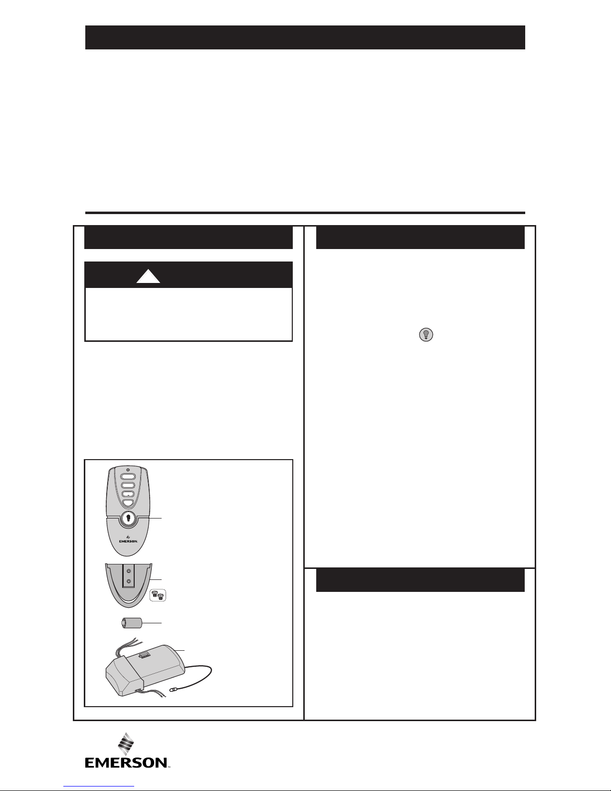
Open the carton containing the Bluetooth
®
Ceiling Fan Control. Remove contents and
check to see that you have received the
following parts:
1. Transmitter (1)
2. Storage Bracket and Hardware (1 set)
3. A23/MN21 12V Alkaline Battery (1)
4. Receiver (1)
Your Emerson Bluetooth®Ceiling Fan Control
consists of a hand-held transmitter and a
receiver. The transmitter is designed to
separately control your ceiling fan speed and
light intensity. There are four push buttons
(0, 1, 2, 3) to set the fan speed and turn the
fan OFF. The light ( ) push button turns
the light ON and OFF and controls the light
intensity. The blue indicator light will illuminate
while any button is pressed, indicating that the
battery is good.
The transmitter is powered by one A23/MN21
12V alkaline battery (supplied). To prevent
possible damage if the battery should leak, be
sure to remove the battery when the control is
not to be used for an extended period of time.
Code switches in the transmitter and receiver
may be set in 16 different positions. If your fan
and light go ON and OFF without using your
control, you may be getting interference from
other remote units such as garage door
openers, car alarms or security systems.
To remedy this situation, change the
combination code in your transmitter and
receiver.
STORAGE BRACKET
TRANSMITTER
A23/MN21 12 V BATTERY
RECEIVER
3
2
1
0
+ A23
4
3
2
1
3
emersonfans.com
Please contact 1-800-654-3545 for further assistance
U.L. Model No.: MR101F
TRANSMITTER
A23/MN21 12 V
BATTERY
BATTERY COMPARTMENT
COVER
+ A23
D
IP
12 34
ON
O
N DIM
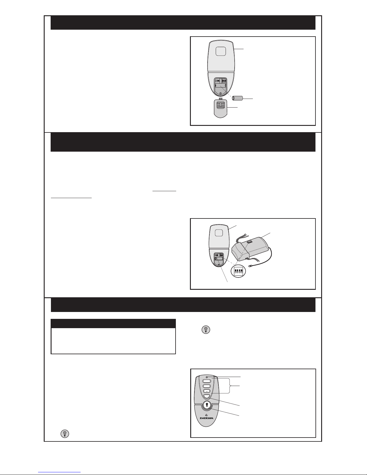
1. Remove the battery compartment cover by
pressing firmly below the arrow and sliding
the cover off the transmitter (retain for
future use).
2. Install one A23/MN21 12V alkaline battery
(supplied).
Your transmitter and receiver have code
switches which must be set in one of 16
possible code combinations. The four levers
(numbered 1, 2, 3, and 4) on the switches are
factory-set in the ON (up) position. Do NOT
use this setting. Change the switch settings as
follows:
1. Slide the four switch levers in the
transmitter to your choice of ON (up) or
OFF (down) positions. Use a ball-point pen
or small screwdriver and slide the levers
firmly up or down.
2. On the receiver, slide the four switch levers
to the same positions as set on the
transmitter. Make sure the levers on both
the transmitter and receiver are in the same
positions, otherwise the fan will not
operate.
3. The additional switch on the transmitter
marked ON and DIM is for dimming control
of lights: Set switch to DIM to allow for
dimming of the lights. Set switch to ON for
full brightness of the lights such as for
fluorescent bulbs.
4. Reinstall the battery compartment cover
onto the transmitter.
Figure 1
CODE SWITCHES
RECEIVER
TRANSMITTER
DIM SWITCH
D
IP
1 2 3 4
ON
ON DIM
+ A23
DIP
1 2 34
ON
4
3
2
1
Figure 2
4. Installation of Battery (Figure 1)
5. Setting Operating Frequency of Transmitter and Receiver
(Figure 2)
3
2
1
0
POWER INDICATOR LIGHT
HIGH TO LOW
BUTTONS
FAN OFF BUTTON
LIGHT BUTTON
Your transmitter has full control of your fan
and light.
NOTE: If your fan has pull chains, prior to
operation of the fan and light from the
transmitter, set the fan speed to HIGH and
turn the light ON.
1. To set the desired fan speed, press one of
the four buttons (0, 1, 2, 3) to operate your
fan from OFF to HIGH speeds.
2. To turn the light ON, press and release the
( ) button.
3. To vary the intensity of the light, hold the
( ) button down until the desired light
intensity is reached, then release the
button.
Note: When turning the light on, light will turn
on at the light intensity previously selected.
IMPORTANT
Fan installation must be completed,
including the installation of the fan
blades, before testing the transmitter.
Figure 3
6. Operation (Figure 3)
 Loading...