

Emerson Personal Lift 381333230 User Manual
Operator’s
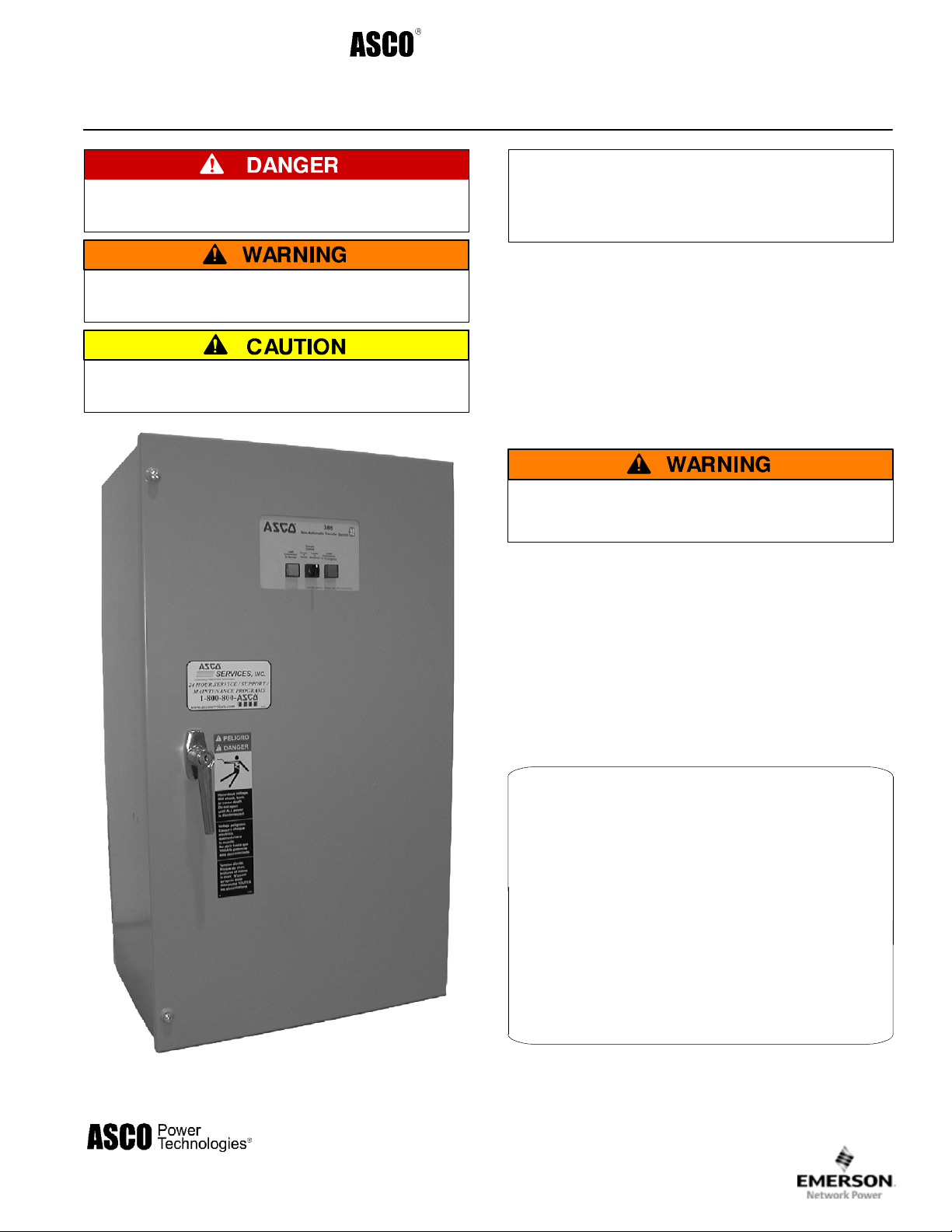
Series 386 Electrically–Operated
Non–Automatic Transfer Switches
Manual
D–design 30 through 230 amps
DANGER is used in this manual to warn of high
voltages capable of causin g shock, burns, or death.
WARNINGisusedinthismanualtowarn
of possible personal injury.
CAUTIONisusedinthismanualtowarn
of possible equipment damage.
Note: Refer to the outline and wiring drawings
provided with yourASCO Series 386 Non–Automatic
Transfer Switch for all installation and connection
details and accessories.
An experienced licensed electrician must install the NonAutomatic Transfer Switch.
Rating Label
Each Non- Automatic Trans fer Switch contains a rating label
to define the loads and fault circuit withstand/closing ratings.
Refer to the label on the Tr ansfer Switch for specific values.
Do not exceed the values on the rating label.
Exceeding the rating can cause personal injury
or serious equipment damage.
Identification Label
The identification label on the Transfer Switch includes
data for each specific ASCO Series 386. Use the switch only
within the limits shown on identification label.
TABLE OF CONTENTS
INSTALLATION 1-1........................
Functional Test 1-2........................
SEQUENCE OF OPERATION 2-1...........
TESTING & SERVICE 3-1..................
Troubleshooting 3-2.......................
ADJUSTMENTS 4-1.......................
OPTIONAL FEATURES 5-1.................
INDEX back cover.........................
30–200 amp sizes
50 Hanover Road, Florham Park, New Jersey 07932–1591 USA
For sales or service call 1 800 800–2726 (ASCO) www.ascopower.com
ASCO POWER TECHNOLOGIES CANADA PO Box 1238, 17 Airport Road, Brantford, Ontario, Canada N3T 5T3
telephone 519 758–8450, fax 519 758–0876, for service call 1 888 234–2726 (ASCO) www.asco.ca
381333–230 C

Catalog Number Identification
Typical ASCO 386 catalog no. for solid neutral, 3 pole, 150 amp, 480 V, N–ATS in Type 1 enclosure:
D 386 A 3 150 N 1 C
Neutral
A –solid
B –switched
C – overlapping
blank – none
load power
connections
emergency power
connections
Phase Poles
2 –singleØ
3 –threeØ
terminals for switch
position contacts
Amperes Voltage Controller Enclosure
30
70
100
150
200 *
* 200 amp.
limited to 480 volts
A 115
B 120
C 208
D 220
E 230
F 240
H 380
K 415
L 440
M 460
N 480
P 550
Q 575
R 600
1 –standard
1X –if
accessories
ordered
C –type1
F –type3R
G –type4
L –type12
blank – open type
J 400
transfer controls
&lights
Controller
Transfer
Switch
maintenance
handle
(see WARNING
under Manual
Operation)
normal power
connections
cable spacers
(see INSTALLATION)
150 amp size in typical enclosure with location of customer connections

Catalog Number Identification
Typical ASCO 386 catalog no. for solid neutral, 3 pole, 230 amp, 480 V, N–ATS in Type 1 enclosure:
D 386 A 3 230 N 1 C
Neutral
A –solid
B –switched
C – overlapping
blank – none
load power
connections
emergency power
connections
Phase Poles
2 –singleØ
3 –threeØ
Amperes Voltage Controller Enclosure
230 **
** 230 amp. limited
to 480 volts
A 115
B 120
C 208
D 220
E 230
F 240
H 380
J 400
K 415
L 440
M 460
N 480
1 –standard
1X –if
accessories
ordered
C –type1
F –type3R
G –type4
L –type12
blank – open type
transfer control
&lights
Transfer Sw i t c h
maintenance handle
(see WARNING under
Manual Operation)
normal power
connections
cable spacers
(see INSTALLATION)
230 amp. size in typical enclosure with location of customer connections
Controller

SECTION 1 INSTALLATION
ASCO386 Non–AutomaticTransfer Switches are factory
wired and tested. Installation requires skid removal then
securing the enclosure to the supporting foundation.
Mounting
Refer to the applicable enclosure outline drawing furnished with this switch and mount the Series 300
according to details and i nstructions shown on diagram.
Line Connections
Refer to the Wiring Diagram provided with your ASCO
386 N–ATS. All wiring must be made in accordance with
the National Electrical Code and local codes.
It is unnecessary to remove pole covers from the transfer
switch. If you do remove them, reinstall them carefully.
De–energize the conductors before making any
line or auxiliary circuitry connections. Be sure
that Normal and Emergency line connections
are in proper phase rotation. Place engine generator starting control in the OFF position. Make
sure engine generator is not in operation.
Three cable spacers are included with 150, 200, and 230
ampere transfer switches. When installing power cables,
run the cables through the cable spacers as shown in
Figure 1–1. Position cable spacers within 1½ inches from
lugs.
The cable spacers must be located as shown
for 150, 200, and 230 ampere transfer switches.
cable spacers
1 ½ inch approximate
cable spacer
Figure 1–1. Cable spacers for 150, 200, & 230 amp.
transfer switches.
Protect the non–automatic transfer switch from
construction grit and metal chips to prevent
malfunction or shortened life of the N–ATS.
Connecting Power Conductors
After the power cables have been tested, connect them to
the appropriate terminal lugs on the transfer switch as
shown on the wiring diagram provided with this ASCO
386. M ake sure the lugs provided are suitable for use with
the cables being installed. Standard terminal lugs are
solderless screw type and will accept the wire sizes listed
on the drawings provided with the ASCO 386. Be careful
when stripping insulation from the cables; avoi d nicking
or ringing the conductor. Remove surface oxides from
cables by cleaning with a wire brush. When aluminum
cable is used, apply joint compound to conductors.
Tighten cable lugs to the torque specified on rating label.
Controller Ground
A grounding wire must be connected to the controller’s
lower left mounting stud. Because the controller is
mounted on the enclosure door, a conductive strap must
be used between the enclosure and the door. This
connection provides proper grounding which does not
rely upon the door hinges.
Harnesses
The transfer switch is connected to the left side of the
controller by a plug–in harness (two plugs).
Auxiliary Circuits
Connect auxiliary circuit wires to appropriate terminals
on transfer switch as shown on the wiring diagram
provided with this ASCO 386 Non–Automatic Transfer
Switch.
1 --- 1
 Loading...