

Page 1
QUICK START GUIDE
GFK-2948A
Sep 2019
PACSystemsTM RX3i
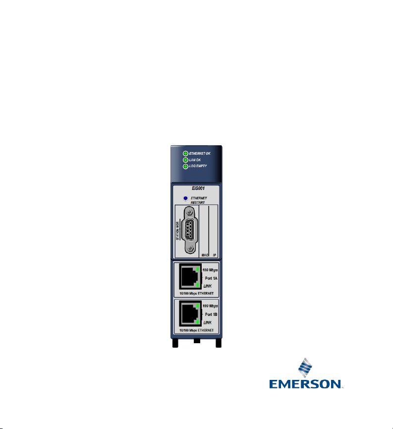
ETHERNET 104 SLAVE MODULE
(IC695EIS001)
Page 2

Quick Start Guide Contents
GFK-2948A Sep 2019
Contents i
Contents
1. User Features ............................................................................................ 1
1.1. Overview ................................................................................................................. 1
1.2. Restart Pushbutton .................................................................................................. 1
1.3. Light-Emitting Diode Indicators (LEDs) .................................................................... 2
1.4. Station Manager Port ............................................................................................... 4
1.5. Ethernet Interface Ports ........................................................................................... 4
2. Hardware Installation ............................................................................... 5
2.1. Initial Checks .......................................................................................................... 5
2.2. Installation Location ................................................................................................ 5
2.3. Installation in Hazardous Areas ................................................................................ 6
2.4. Module Installation .................................................................................................. 7
2.5. Station Manager Port Connections .......................................................................... 8
2.6. Ethernet Port Connections ...................................................................................... 8
3. Configuration ........................................................................................... 9
3.1. Configure EIS001 into Target CPU ........................................................................... 9
3.2. Confirm EIS001 Communication with the CPU ...................................................... 11
3.3. Program COMMREQs for EIS001 Initialization ....................................................... 12
3.4. Complete the RX3i Application .............................................................................. 12
3.5. Verify IEC 104 Network Operations ....................................................................... 12
4. Status and Diagnostic Data ..................................................................... 14
4.1. Module Status Data ............................................................................................... 14
4.2. Problems during Power-Up and Reset ................................................................... 15
5. Additional Information ........................................................................... 17
5.1. PACSystems RX3i User Manuals ............................................................................. 17
5.2. Information about IEC 60870-5-104 ...................................................................... 17
Page 3

GFK-2948A Sep 2019
Warning Notes as used in this Publication
Warning
Warning Notices are used in this publication to emphasize that hazardous
voltages, currents, temperatures, or other conditions that could cause
personal injury exist in this equipment or may be associated with its use.
In situations where inattention could cause either personal injury or damage
to equipment, a Warning notice is used.
Note: Notes merely call attention to information that is especially significant to understanding
and operating the equipment.
These instructions do not purport to cover all details or variations in equipment, nor to provide
for every possible contingency to be met during installation, operation, and maintenance. The
information is supplied for informational purposes only, and Emerson makes no warranty as to
the accuracy of the information included herein. Changes, modifications, and/or improvements
to equipment and specifications are made periodically and these changes may or may not be
reflected herein.
It is understood that Emerson may make changes, modifications, or improvements to the
equipment referenced herein or to the document itself at any time. This document is intended
for trained personnel familiar with the Emerson products referenced herein.
Emerson may have patents or pending patent applications covering subject matter in this
document. The furnishing of this document does not provide any license whatsoever to any of
these patents.
Emerson provides the following document and the information included therein as-is and
without warranty of any kind, expressed or implied, including but not limited to any implied
statutory warranty of merchantability or fitness for particular purpose.
Page 4

Quick Start Guide Section 1
GFK-2948A Sep 2019
User Features 1
1. User Features
1.1. Overview
The PACSystems RX3i Ethernet 104 Server Module, catalog number IC695EIS001
implements the IEC 104 protocol, server side. It permits a PACSystems RX3i controller
to be connected to an Ethernet network using a standard Ethernet TCP/IP connection
scheme, and serve data to one or many IEC 104 clients, using interrogation polls, or
report by exception (RBE) functions to retrieve data. Each IEC 104 Server module can
be connected to IEC 104 Clients over the IEC 104 network.
Two auto-sensing 10BaseT/100BaseTX RJ-45 shielded twisted-pair Ethernet ports
permit direct connection to either a 10BaseT or 100BaseTX IEEE 802.3 network
without an external transceiver. Line, Star and Daisy Chain topologies are supported.
1.2. Restart Pushbutton
The recessed Restart pushbutton can be used to restart the module without cycling
power. The restart operation begins when the pushbutton is released.
Page 5

Quick Start Guide Section 1
GFK-2948A Sep 2019
User Features 2
1.3. Light-Emitting Diode Indicators (LEDs)
LED
State
Indicates
ETHERNET OK
LAN OK
LOG EMPTY
Fast Blink
Off
Off
Performing
Diagnostics
ETHERNET OK
LAN OK
LOG EMPTY
Slow Blink
Off
Off
Waiting for Ethernet
configuration from
CPU
ETHERNET OK
LAN OK
LOG EMPTY
Slow Blink†
On/Traffic/Off
Slow Blink†
(† EOK
and STAT
blink in
unison)
Waiting for IP
Address
ETHERNET OK
LAN OK
LOG EMPTY
On
On/Traffic/Off
On/Off
Operational
ETHERNET OK
LAN OK
LOG EMPTY
Blink error code
Off
Off
Hardware failure.
Refer to GFK-2949,
EIS001 User Manual
for blink code
definitions.
ETHERNET OK
LAN OK
LOG EMPTY
Slow Blink†
Slow Blink†
Slow Blink†
(† All LEDs
blink in
unison)
Firmware Update
(pattern is the same
for awaiting or
performing load)
Page 6

Quick Start Guide Section 1
GFK-2948A Sep 2019
User Features 3
LED
State
Indicates
Port LEDs (one pair for Port 1A, second pair for Port 1B)
100 Mbps
On
Off
100 Mbps Active
100 Mbps Not
Achieved
LINK
Rapid Blink
Off
Traffic Detected on
Port
No Traffic Detected
on Port
Page 7

Quick Start Guide Section 1
GFK-2948A Sep 2019
User Features 4
1.4. Station Manager Port
The Station Manager Port is an RS-232 serial port intended to permit the user to
perform set-up operations or monitoring functions, but is not intended for
permanent connection. The Station Manager port provides a means to access the
module through a terminal interface. This function can alternatively be accessed over
the Ethernet network.
A Station Manager interface application can be downloaded from Emerson Global
Customer Care by searching KB14092 or following the link
https://www.emerson.com/Industrial-Automation-Controls/support.
1.5. Ethernet Interface Ports
The module provides two auto-sensing 10BaseT / 100BaseTX RJ-45 shielded twisted
pair Ethernet ports for connection to either a 10BaseT or 100BaseTX IEEE 802.3
network. The port automatically senses the speed (10Mbps or 100Mbps), duplex
mode (half duplex or full duplex) and cable (straight-through or crossover) attached
to it with no intervention required. There is only one interface to the network (only
one Ethernet MAC address and only one IP address).
Page 8

Quick Start Guide Section 2
GFK-2948A Sep 2019
Hardware Installation 5
2. Hardware Installation
2.1. Initial Checks
Upon receiving your RX3i equipment, carefully inspect all shipping containers for
damage. If any part of the system is damaged, notify the carrier immediately. The
damaged shipping container should be retained as evidence for inspection by the
carrier. As the consignee, it is your responsibility to register a claim with the carrier in
the event of damage incurred during shipment.
After unpacking the RX3i equipment, record all serial numbers. Serial numbers are
required should you need to contact Customer Care during the warranty period. All
shipping containers and all packing material should be saved should it be necessary
to transport or ship any part of the system.
Verify that all components of the system have been received and that they agree with
your order.
2.2. Installation Location
This product is intended for use with the RX3i system. Its components are considered
open equipment (having live electrical parts that may be accessible to users) and
must be installed in an ultimate enclosure that is manufactured to provide safety. At
a minimum, the enclosure shall provide a degree of protection against solid objects
as small as 12 mm (for example fingers). This equates to a NEMA/UL Type 1 enclosure
or an IP20 rating (IEC 60529) providing at least a pollution degree 2 environment. For
details about installing RX3i rack systems, refer to GFK-2314, RX3i System Manual.
If you need technical help, contact Technical Support. For phone numbers and email
addresses, refer to GFK-2949, PACSystems RX3i Ethernet IEC 104 Server Module User
Manual the section, Contact Information.
Page 9

Quick Start Guide Section 2
GFK-2948A Sep 2019
Hardware Installation 6
2.3. Installation in Hazardous Areas
The following information is for products bearing the UL marking for Hazardous Areas
or ATEX marking for explosive atmospheres:
CLASS 1 DIVISION 2 GROUPS ABCD
• This equipment is an open-type device and is meant to be installed in an
enclosure suitable for the environment that is only accessible with the use
of a tool.
• Suitable for use in Class I, Division 2, Groups A, B, C and D Hazardous
Locations, or nonhazardous locations only.
WARNING
• EXPLOSION HAZARD - SUBSTITUTION OF COMPONENTS MAY IMPAIR
SUITABILITY FOR CLASS I, DIVISION 2.
• WHEN IN HAZARDOUS LOCATIONS, TURN OFF POWER BEFORE REPLACING
OR WIRING MODULES; AND
• DO NOT CONNECT OR DISCONNECT EQUIPMENT UNLESS POWER HAS BEEN
SWITCHED OFF OR THE AREA IS KNOWN TO BE NONHAZARDOUS.
ATEX Zone 2
The EIS001 must be mounted in an enclosure certified in accordance with EN6007915 for use in Zone 2, Group IIC and rated IP54. The enclosure shall only be able to be
opened with the use of a tool.
ATEX Marking
II 3 G Ex nA IIC T5 X Ta: 0 - 60C
Page 10

Quick Start Guide Section 2
GFK-2948A Sep 2019
Hardware Installation 7
2.4. Module Installation
The EIS001 is compatible with all RX3i CPU (no model restrictions). The EIS001
supports insertion into and removal from an Rx3i backplane which is under power.
This module may be installed in any available RX3i backplane slot in the main (CPU)
rack.
Module Insertion
• RX3i rack power may be off or on (hot insertion).
• Holding the module firmly, align the module with the correct slot and
connector. The installation slot must match the slot selected for the module
location in the Proficy* Machine Edition application.
• Engage the plastic hook at the top rear of the module with the corresponding
exposed ridge in the backplane.
• Swing the module down until the connector at the rear of the module securely
engages the mating backplane connector.
• Visually inspect the module to be sure it is properly seated.
Module Connections
• Attach Cat5 or higher-rated cables to one or both RJ-45 connectors marked
Port 1A and Port 1B, as the application demands.
• As needed, attach the RS-232 serial port connection to the D-connector
marked Station Manager.
Page 11

Quick Start Guide Section 2
GFK-2948A Sep 2019
Hardware Installation 8
2.5. Station Manager Port Connections
Pin No†
Signal
Direction
Description
1
DCD
IN
Data Carrier Detect
2
TX
OUT
Transmit Data
3
RX
IN
Receive Data
4
DSR
IN
Data Set Ready
5
GND
Signal Ground
6
DTR
OUT
Data Terminal Ready
7
CTS
IN
Clear to Send
8
RTS
OUT
Ready to Send
9
RI
IN
Ring Indicator
†
Pin 1 is at the bottom right of the Station Manager Port connector as viewed from
the front of the module.
Note: Station Manager software configuration is performed in the Station Manager
tab of PME.
2.6. Ethernet Port Connections
The module provides two RJ-45 10BaseT/100BaseTX Ethernet Network Port
Connectors.
Page 12

Quick Start Guide Section 3
GFK-2948A Sep 2019
Configuration 9
3. Configuration
You will need:
• PACSystems RX3i CPU Firmware 7.18 or later.
• Proficy Machine Edition version 8.50 SIM 9 or later.
• GFK-2949, PACSystems RX3i Ethernet 104 Server Module User Manual, available
from the Emerson Global Support https://www.emerson.com/Industrial-
Automation-Controls/support. You will need to refer to this manual to fully
configure and commission the EIS001.
3.1. Configure EIS001 into Target CPU
Start the PME application, then open or create the project to contain the EIS001. After
configuring the rack, power supply, and CPU in the Project tab of the Navigator, select
a vacant slot in the main rack into which the EIS001 is to be installed. Right-click on
that slot icon and select Add Module. From the Communications tab of the Module
Catalog, select the IC695EIS001 module. This adds the EIS001 module from the dropdown list into that location. Install the physical EIS001 module into the corresponding
location.
Page 13

Quick Start Guide Section 3
GFK-2948A Sep 2019
Configuration 10
Once added to the rack location, set up the EIS001 parameters in the Settings and RS232 Port (Station Manager) tabs as needed for the application.
Page 14

Quick Start Guide Section 3
GFK-2948A Sep 2019
Configuration 11
3.2. Confirm EIS001 Communication with the CPU
Power up the target RX3i system. In PME, go “online”, right-click on the target and
select Online Commands, Show Status…, Details, to display the Device
Information Details window. This queries the CPU and all modules present on all
racks in the system, whether configured or not. If the EIS001 will appear as a ETM
module, displayed in the list similar to the following screenshot, it indicates that the
module has powered up as expected, is communicating with the CPU over the rack
backplane, and that it is ready for further configuration.
Page 15

Quick Start Guide Section 3
GFK-2948A Sep 2019
Configuration 12
3.3. Program COMMREQs for EIS001 Initialization
A single COMMREQ instruction must be passed from the CPU to the EIS001 in order
to configure the IEC 104 Server module attributes. These are explained in the
Configuration portion of GFK-2949, Ethernet IEC 104 Server Module User Manual. The
COMMREQ is executed once following power-up of the EIS001 and can be added to
an existing ladder logic program.
3.4. Complete the RX3i Application
The variables created in the previous step are used to develop an RX3i application
program. This program, along with the hardware configuration and network
configuration is then downloaded to the RX3i controller for validation and
deployment.
3.5. Verify IEC 104 Network Operations
After the COMMREQ has been executed, verify the data exchange on the Network is
as expected. Establish that data originating at each Client is passed to the RX3i tables
per the IEC 104 configuration. Verify also that data originating at the IEC 104 Server
is passed to each Client per the corresponding IEC 104 configuration. IEC 104
network activity verification may be part of the IEC 104 configuration (heartbeat bits,
for instance) or may be accomplished through the Station Manager interface. Refer
Page 16

Quick Start Guide Section 3
GFK-2948A Sep 2019
Configuration 13
to GFK-2949, PACSystems RX3i Ethernet 104 Server Module User Manual for more
information.
Page 17

Quick Start Guide Section 4
GFK-2948A Sep 2019
Status & Diagnostic Data 14
4. Status and Diagnostic Data
4.1. Module Status Data
Bit#
LAN Interface Status Bits
0 (lsb)
Port 1A Full Duplex
1
Port 1A 100 Mbps
2
Port 1B Full Duplex
3
Port 1B 100 Mbps
4
Network Time Locked
5
Redundant IP Address is Active
6-7
Reserved
8
Any Channel Error (error on any channel)
9
Used with Plugin Application 1
10
Used with Plugin Application 2, IEC 104 Server
11
Used with Plugin Application 3
12
LAN OK
13
Resource Problem
14
Module Over-Temperature
15
LAN Interface OK
16-79
Not Used
Page 18

Quick Start Guide Section 4
GFK-2948A Sep 2019
Status & Diagnostic Data 15
4.2. Problems during Power-Up and Reset
Certain conditions can prevent the module from becoming operational.
Problem
Indication
Action
Hardware failure
All Indicator LEDs off.
Module unresponsive.
Return the module Emerson
Invalid bootstrap
image
Invalid boot
image
No Indicator LEDs turn on
and the module is
unresponsive, or
The STATUS LED is solid
green and is the only LED
on.
Fatal power-up
initialization
failure
Fatal Error LED blink code
Note the blink code and
contact Customer Service.
Non-fatal
initialization
failure
Module powers up normally,
but an entry is added to the
Local Log table and the RX3i
CPU fault table.
Note the fault and contact
Customer Service.
Module does not
contain hardware
identity info
Fatal Error LED blink code
Note the blink code and
contact Customer Service.
Module operates
with limited point
counts
Only a small number of IEC
104 points are accessible, no
matter the configuration
Module is operating without a
license, Contact customer
service
Page 19

Quick Start Guide Section 4
GFK-2948A Sep 2019
Status & Diagnostic Data 16
Problem
Indication
Action
Module shuts
down after 4
hours
IEC 104 traffic stops after 4
hours of operation
Module is operating without a
license, Contact customer
service
Page 20

Quick Start Guide Section 5
GFK-2948A Sep 2019
Additional Information 17
5. Additional Information
5.1. PACSystems RX3i User Manuals
GFK-2949, PACSYstems RX3i Ethernet IEC 104 Server Module User Manual
GFK-2222, PACSystems RX3i and RX7i CPU Reference Manual
GFK-2224, TCP/IP Ethernet Communications for PACSystems RX3i & RX7i User’s
Manual
GFK-2225, TCP/IP Ethernet Communications for PACSystems Station Manager
Manual
GFK-2314, PACSystems RX3i System Manual
User manuals, product updates and other information sources are available on the
Support website, https://www.emerson.com/Industrial-Automation-
Controls/support under Controllers and IO, RX3i Controllers.
5.2. Information about IEC 60870-5-104
For detailed information about IEC 60870-5-104 and related protocols (101, and
103), a web search using those key words will return sites with relivant information,
as there is not one specific site for this standard such as with other protocols.
Page 21

QUICK START GUIDE
GFK-2948A
Sep 2019
Technical Support & Contact Information:
Home link: http://www.Emerson.com/Industrial-Automation-Controls
Knowledge Base: https://www.emerson.com/Industrial-Automation-Controls/support
Note: If the product is purchased through an Authorized Channel Partner, please contact
the seller directly for any support.
Emerson reserves the right to modify or improve the designs or specifications of the
products mentioned in this manual at any time without notice. Emerson does not assume
responsibility for the selection, use or maintenance of any product. Responsibility for
proper selection, use and maintenance of any Emerson product remains solely with the
purchaser.
© 2019 Emerson. All rights reserved.
Emerson Terms and Conditions of Sale are available upon request. The Emerson logo is a
trademark and service mark of Emerson Electric Co. All other marks are the property of
their respective owners.
 Loading...