

Page 1
Application Note (Syllabus)
GFK-3167A
April 2020
PACMOTION VFD
APPLICATION NOTE (SYLLABUS)
Page 2

PACMotion VFD Syllabus
GFK-3167A April 2020
ii
Contents
Revision History .................................................................... iv
Introduction VFD Basic Setup ................................................. 1
Signal Wiring Example ............................................................................................. 1
IO Configuration ..................................................................................................... 2
Power Wiring Example ............................................................................................ 3
NOTE 1: Modbus/TCP Ethernet Demo (Demo Case with Modbus/TCP
Option Card) ...................................................................................... 4
Note 2: PROFINET Demo (Demo Case with PROFINET Option Card .......................... 4
NOTE 3: Modbus RTU Serial Demo (RS-485 2-wire) and Modbus/TCP Demo
5
NOTE 4: Modbus/TCP Ethernet Demo .......................................................... 5
NOTE 5: Modbus/TCP User Defined Function Block Examples ..................... 6
NOTE 6: PROFINET User Defined Function Block Examples ......................... 6
NOTE 7: Using Bluetooth USB or Serial Cable to PACMotion with VFD Suite:
7
NOTE 8: PACMotion Fieldbus Option Modules and Setup ........................... 7
NOTE 9: PACMotion VFD Fieldbus PDI/PDO Data Map and Addressing ...... 8
NOTE 10: PACMotion VFD Complete PDI/PDO Data Map and Addressing .. 8
NOTE 11: PACMotion VFD Demo Case Details ............................................. 9
Modbus/TCP Ethernet Demo (Note 1) ................................... 10
PROFINET Controller Demo (Note 2) ..................................... 13
VFD Settings ......................................................................................................... 13
VFD I/O Signals ...................................................................................................... 13
Option Module Details .......................................................................................... 14
Bus Specific Technical Data ................................................................................... 15
Hardware Insertion and Removal ........................................................................... 15
PROFINET Slave Module Settings ........................................................................... 15
Starting the system ............................................................................................... 15
Supporting Files .................................................................................................... 16
PROFINET Process Data Exchange.......................................................................... 16
Fieldbus Connection Timeout ................................................................................ 16
Page 3

PACMotion VFD Syllabus
GFK-3167A April 2020
iii
MODBUS RTU SERIAL DEMO (NOTE 3) ......................................... 17
Supporting Files .................................................................................................... 20
Modbus RTU Connection Timeout ......................................................................... 21
Drive Parameter Access ......................................................................................... 21
MODBUS/TCP DEMO (NOTE 4) .................................................. 22
Supporting Files .................................................................................................... 23
Modbus/TCP Connection Timeout......................................................................... 23
USER DEFINED FUNCTION BLOCK – MODBUS/TCP (NOTE 5) ............. 25
USER DEFINED FUNCTION BLOCK – PROFINET (NOTE 6) ................ 30
Setting Fieldbus Connection Timeout Preferences ................................................. 37
PROFINET Process Data Exchange Map .................................................................. 38
Supporting Files .................................................................................................... 39
Other Modbus/TCP UDFBs ..................................................................................... 40
Supporting Files .................................................................................................... 40
Modbus/TCP UDFB to VFD PME Projects ...................................................... 40
Modbus/TCP UDFB to VFD Toolchest Drawer .............................................. 41
Modbus/TCP UDFB to VFD XML Block Code ................................................. 41
BLUETOOTH USB AND SERIAL CABLE (NOTE 7) ............................... 42
Communications to the VFD ................................................................................. 42
Serial RS-485 Communications to the VFD ............................ 48
Supporting Files .......................................................................................... 49
PACMotion VFD Fieldbus Option Modules and Setup (NOTE 8)
50
MODBUS/TCP FIELDBUS OPTION MODULE ................................................................... 50
Bus Specific Technical Data ................................................................................... 50
IP Address Setup ................................................................................................... 51
Start-Up and Operation ......................................................................................... 51
LEDs 51
Network Status LED .................................................................................... 52
Module Status LED ...................................................................................... 52
Modbus TCP Data Exchange ........................................................................ 52
Modbus TCP Connection Timeout ............................................................... 53
Page 4

PACMotion VFD Syllabus
GFK-3167A April 2020
iv
Drive Parameter Access – Direct Address Method ....................................... 53
Drive Parameter Access – Indirect Address Method ..................................... 53
PROFINET FIELDBUS OPTION MODULE............................................................. 54
Bus Specific Technical Data ......................................................................... 54
Hardware Insertion and Removal ................................................................ 55
PDO/PDI Data Map and Addressing (Note 9) ......................... 56
Modbus/TCP PDO Data (or Built-in Modbus RTU Serial Port) . 56
Modbus/TCP or RTU PDI Data ................................................................................ 57
PROFINET PDO Data .............................................................................................. 59
PROFINET PDI Data ................................................................................................ 61
PACMotion VFD Data Map and Addressing (Note 10) ............ 63
Complete Address Mapping Modbus/TCP, Modbus RTU, PROFINET ....................... 63
PACMotion VFD Demo Case Details (Note 11) ....................... 64
Quickpanel to CPE100 (Ethernet) and CPE100 to VFD (PROFINET) ......................... 64
Quickpanel to CPE100 (Ethernet) and CPE100 to VFD (PROFINET) ......................... 65
PACMotion VFD Demo Case and Factory Reset ...................................................... 67
General Contact Information ................................................................................. 68
Technical Support ................................................................................................. 68
Revision History
Revision
Date
Description
A
April 2020
Initial Release
Page 5
PACMotion VFD Syllabus
GFK-3167A April 2020
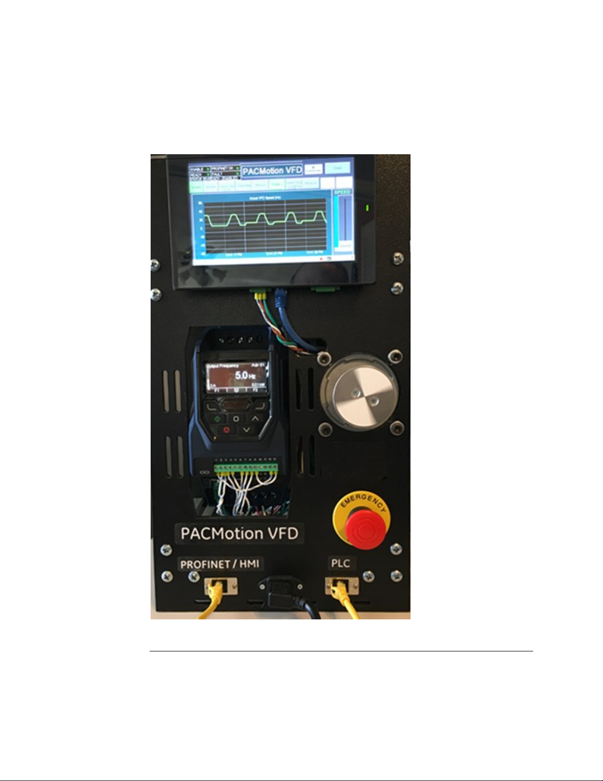
PACMotion VFD Syllabus 1
Introduction VFD Basic Setup
Basic overview for setup and operation of the PACMotion VFD.
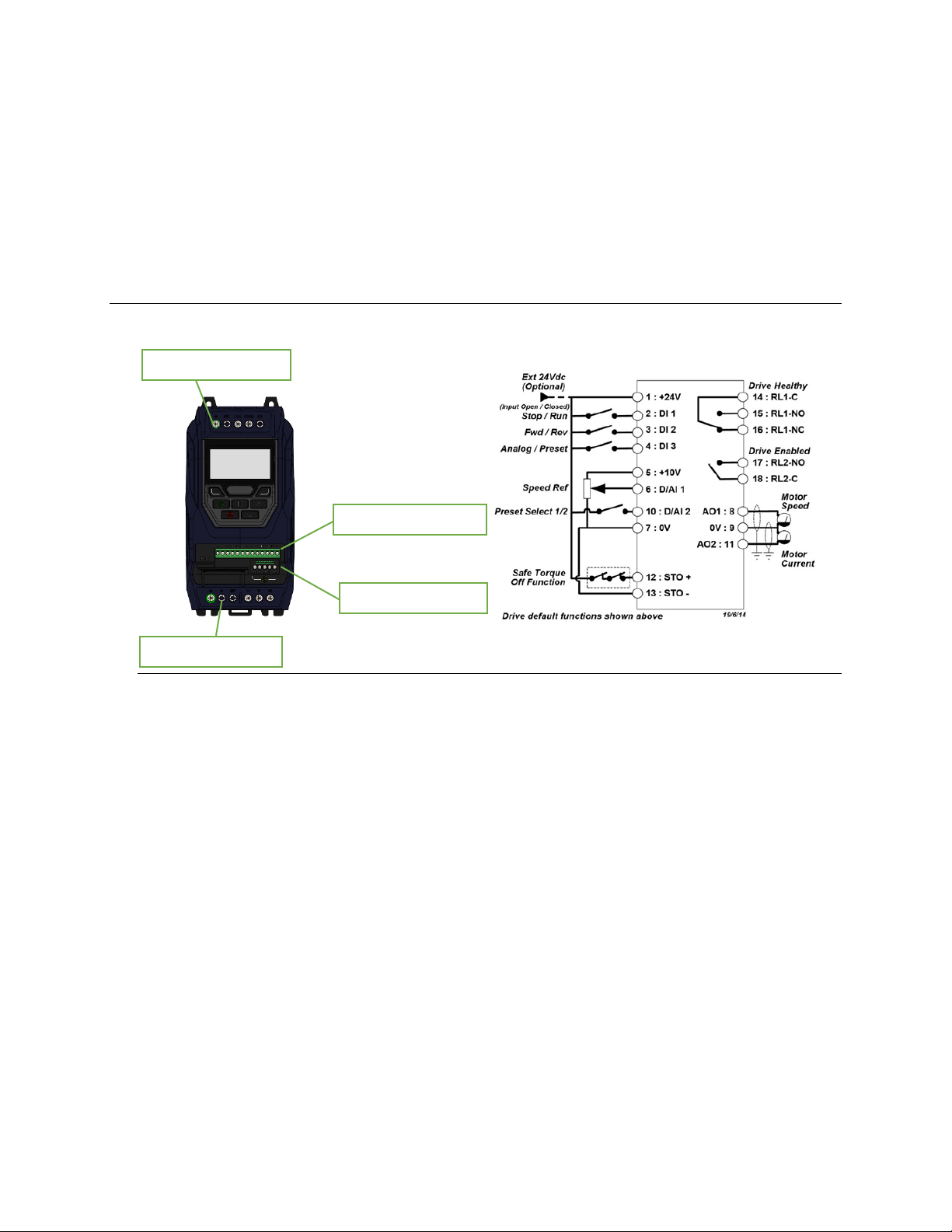
Signal Wiring Example
Figure 1: Signal Wiring Example
Terminals 1 - 13
Terminals 14 - 18
G, L1, L2, L3
G, +, BR, U, V, W
Page 6

PACMotion VFD Syllabus
GFK-3167A April 2020
PACMotion VFD Syllabus 2
IO Configuration
Default configuration for I/O given here. Refer to GFK-3111 and GFK-3112 for details
Figure 2: IO Configuration (Pinout)
Page 7
PACMotion VFD Syllabus
GFK-3167A April 2020
PACMotion VFD Syllabus 3
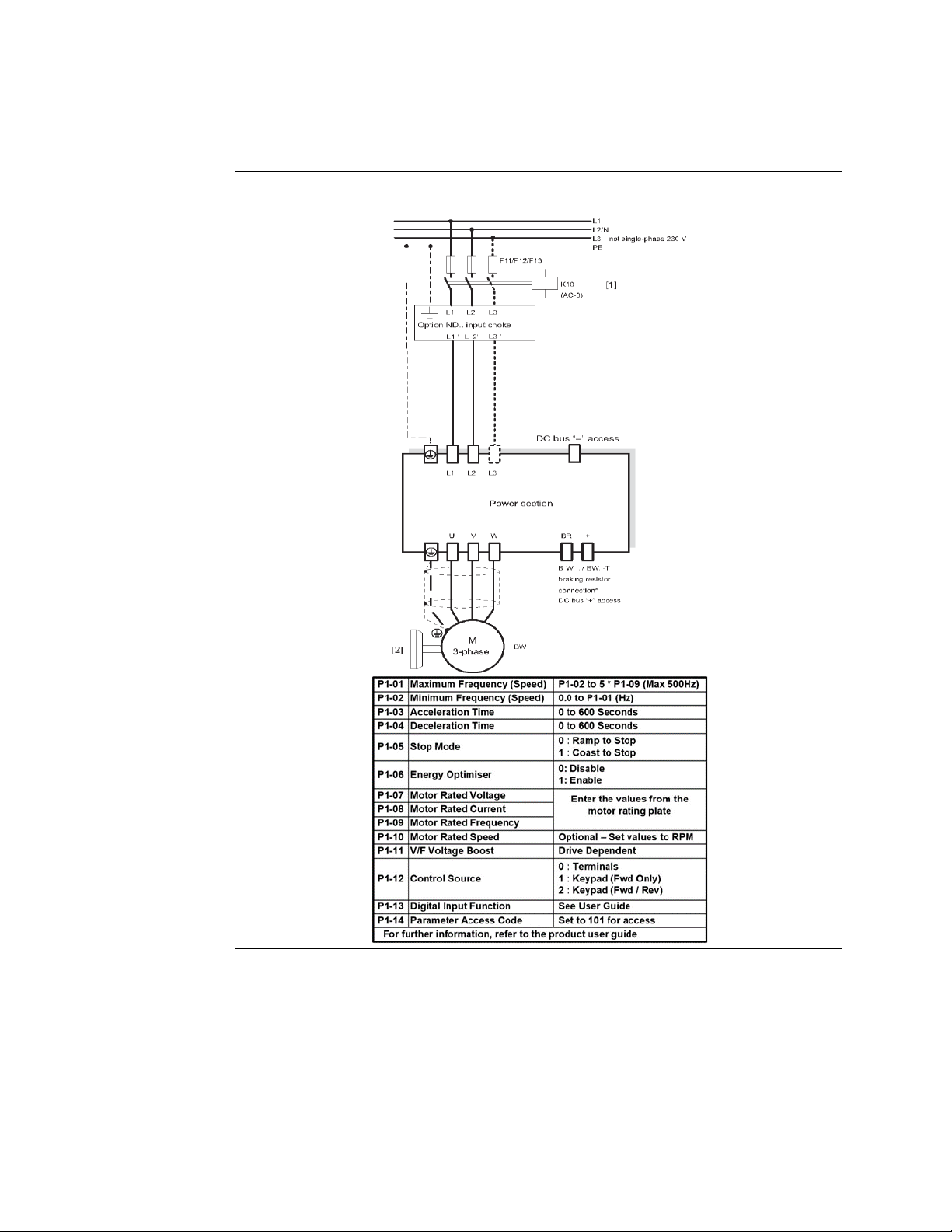
Power Wiring Example
Figure 3: Power wiring and Group 1 Parameters Example (VFD/Motor Setup)
Related Documentation
For more details on wiring and setup refer to documents:
• GFK-3111 PACMotion VFD AC Variable Speed Drive User Guide
• GFK-3112 PACMotion VFD AC Variable Speed Drive Advanced User Guide.
Page 8
PACMotion VFD Syllabus
GFK-3167A April 2020
PACMotion VFD Syllabus 4
PACMotion VFD Syllabus
A collection of technical Application Notes and Data
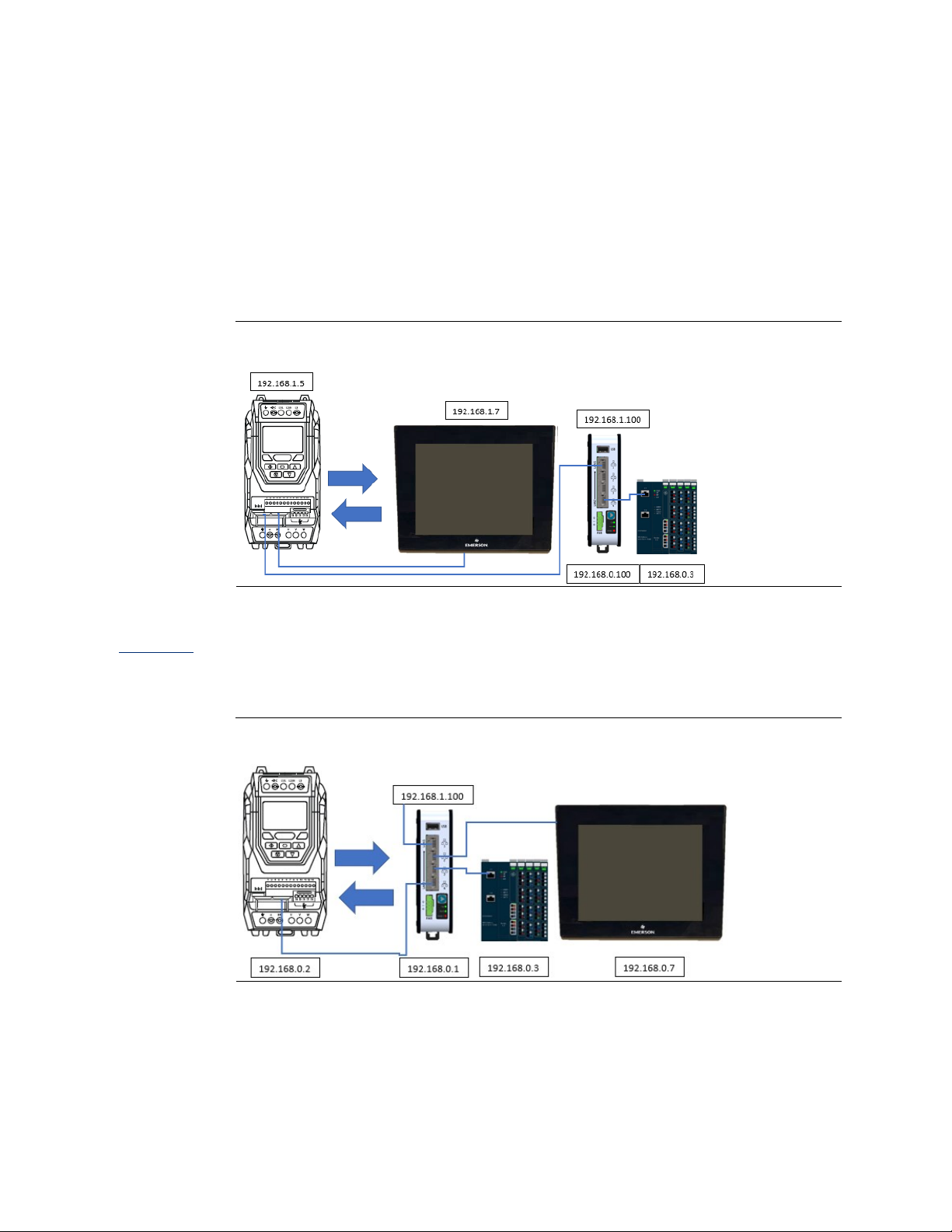
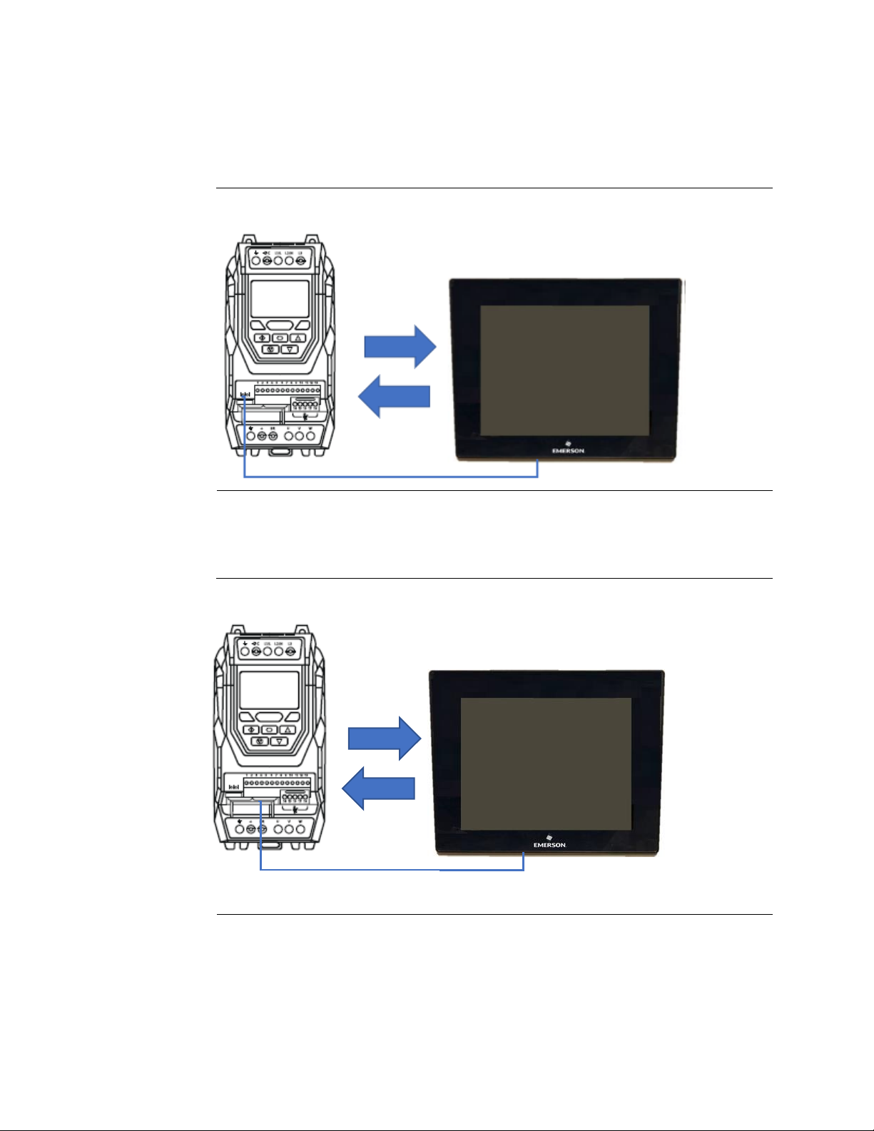
NOTE 1: Modbus/TCP Ethernet Demo (Demo Case with Modbus/TCP Option Card)
Figure 4: CPE100 TO VFD VIA MODBUS/TCP OPTION MODULE WITH QUICKPANEL
Note 2: PROFINET Demo (Demo Case with PROFINET Option
Card
Figure 5: CPE100 TO VFD VIA PROFINET OPTION MODULE WITH QUICKPANEL
Page 9
PACMotion VFD Syllabus
GFK-3167A April 2020
PACMotion VFD Syllabus 5
NOTE 3: Modbus RTU Serial Demo (RS-485 2-wire) and Modbus/TCP Demo
Figure 6: Quickpanel Plus or pc w/PME simulator to VFD Built-in Serial Port
NOTE 4: Modbus/TCP Ethernet Demo
Figure 7: Quickpanel Plus or pc w/PME simulator to VFD Modbus/TCP Option Module
Page 10
PACMotion VFD Syllabus
GFK-3167A April 2020
PACMotion VFD Syllabus 6
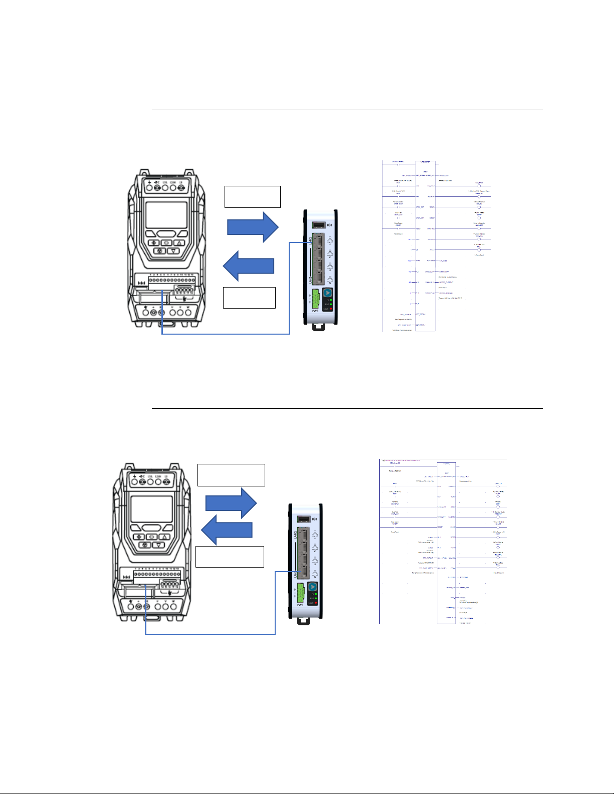
NOTE 5: Modbus/TCP User Defined Function Block Examples
Figure 8: CPE100 to VFD Modbus/TCP Option Module
NOTE 6: PROFINET User Defined Function Block Examples
Figure 9: CPE100 to VFD PROFINET Option Module
PDO1 - 4
PDI1 - 4
%AI1 to 8
%AQ1 to 4
Page 11
PACMotion VFD Syllabus
GFK-3167A April 2020
PACMotion VFD Syllabus 7
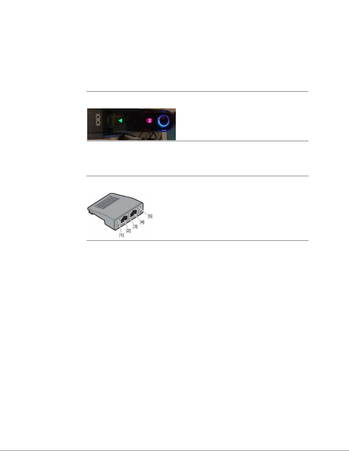
NOTE 7: Using Bluetooth USB or Serial Cable to PACMotion with VFD Suite:
Figure 10: Bluetooth BLE USB Stick
NOTE 8: PACMotion Fieldbus Option Modules and Setup
Figure 11: Fieldbus Option Module
Page 12
PACMotion VFD Syllabus
GFK-3167A April 2020
PACMotion VFD Syllabus 8
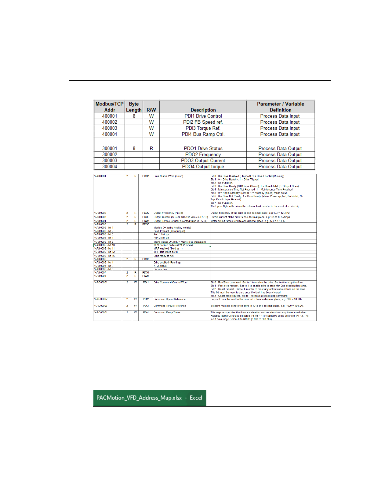
NOTE 9: PACMotion VFD Fieldbus PDI/PDO Data Map and Addressing
Figure 12:
PACM
OTION
VFD F
IELDBUS
PDI/PDO D
ATA MAP AND ADDRESSING
NOTE 10: PACMotion VFD Complete PDI/PDO Data Map and Addressing
Page 13
PACMotion VFD Syllabus
GFK-3167A April 2020
PACMotion VFD Syllabus 9
NOTE 11: PACMotion VFD Demo Case Details
Page 14
PACMotion VFD Syllabus Section 2
GFK-3167A April 2020
Modbus/TCP Ethernet Demo 10
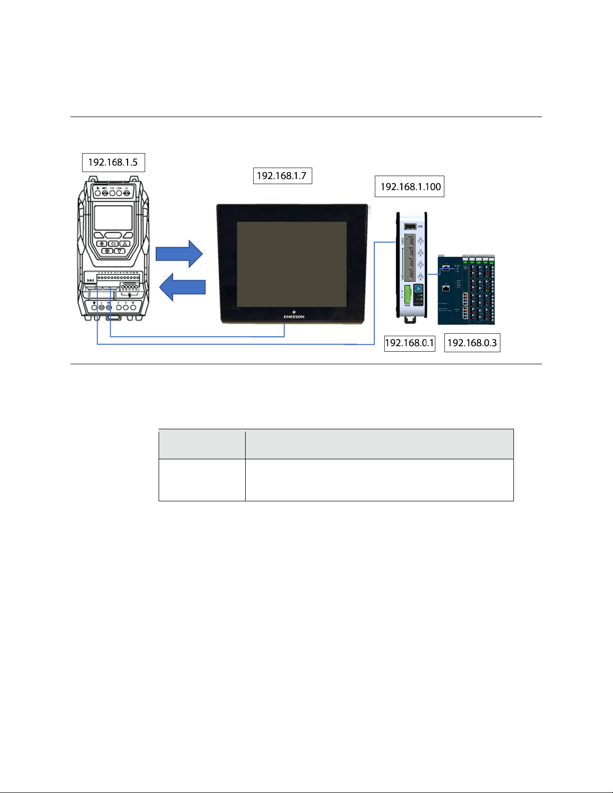
Modbus/TCP Ethernet Demo (Note 1)
Figure 13: Modbus/TCP Ethernet Configuration
This Demo uses the CPE100 as the Initiating device for Modbus/TCP communications.
VFD Parameters
1. Set to the following VFD parameter values:
Parameter
Value and Description
P1-12
P1-14
P5-05
4 (Fieldbus)
201 (Extended Menu Access)
0.0 (Disable communication loss timeout)
QuickPanel Plus Ethernet Settings
2. Set the following IP Address/Mask:
IP address = 192.168.1.7
Subnet mask = 255.255.255.0
VFD Modbus/TCP Option Module settings
3. Use a DHCP server or the HMS IPConfig software to set the IP address of the
Modbus/TCP module. Use the following settings:
IP address = 192.168.1.5
Subnet mask = 255.255.255.0
Page 15

PACMotion VFD Syllabus Section 2
GFK-3167A April 2020
Modbus/TCP Ethernet Demo 11
Starting the system
4. As shown in the picture above, connect one ethernet port of the VFD
Modbus/TCP option module to the QuickPanel and connect the other ethernet
port of the VFD Modbus/TCP option module to the top port of CPE100.
5. Power up the devices.
6. Using a laptop PC with PAC Machine Edition, load in the PAC Machine Edition
project:
“VFD_DEMOCASE_MBTCP_Vx” and Download/Run the CPE100 and QuickPanel
targets. This will use the CPE100 as a Modbus/TCP Master.
7. The QuickPanel Screen should show live PDI/PDO Data. Information on this data
is given below.
Modbus/TCP Process Data Exchange
The mapping of Process Data Output/Input to Modbus/TCP Registers is shown below.
Process Data Word
Modbus/TCP Register1 *
PDO1
300001
PDO2
300002
PDO3
300003
PDO4
300004
PDI1
400001
PDI2
400002
PDI3
400003
PDI4
400004
Modbus/TCP Connection Timeout
The VFD Modbus/TCP interface allows the user to set the “Communication Loss Timeout”
and “Communication Loss Action” values. These parameters are at addresses P5-05 and
P5-06 respectively. The Timeout units are 1 = 0.1 sec and the range is from 0.0 (disable) to
5.0 seconds. A setting of 0.0 seconds will allow the VFD to continue running if
communications is lost.
1
Modbus Clients may address the first Modbus register as register 300001/400001. This assumes an address offset starting at 1. For
Clients that use zero based addressing just subtract 1.
Page 16

PACMotion VFD Syllabus Section 2
GFK-3167A April 2020
Modbus/TCP Ethernet Demo 12
Drive Parameter Access
The Modbus/TCP Interface allows the user to read/write the drive parameters. To perform
this function, the user can directly access the parameter. Simply add the parameter
number to the Modbus offset of 400000.
For example:
Read parameter P1-01 (Maximum Frequency), perform the following
Read Modbus/TCP Address 400101 value (scaling in 0.1 Hz).
Write parameter P1-01 (Maximum Frequency) = 60.0 Hz, perform the following
Write to Modbus/TCP Address 400101 value = 600 (scaling in 0.1 Hz)
Supporting Files
Figure 14: VFD Demo Case file
VFD_DEMOCASE_MBTCP_V2. zip
Right-click the icon to Copy the file.
Page 17
PACMotion VFD Syllabus Section 3
GFK-3167A April 2020
CPE100 to VFD PROFINET Demo 13
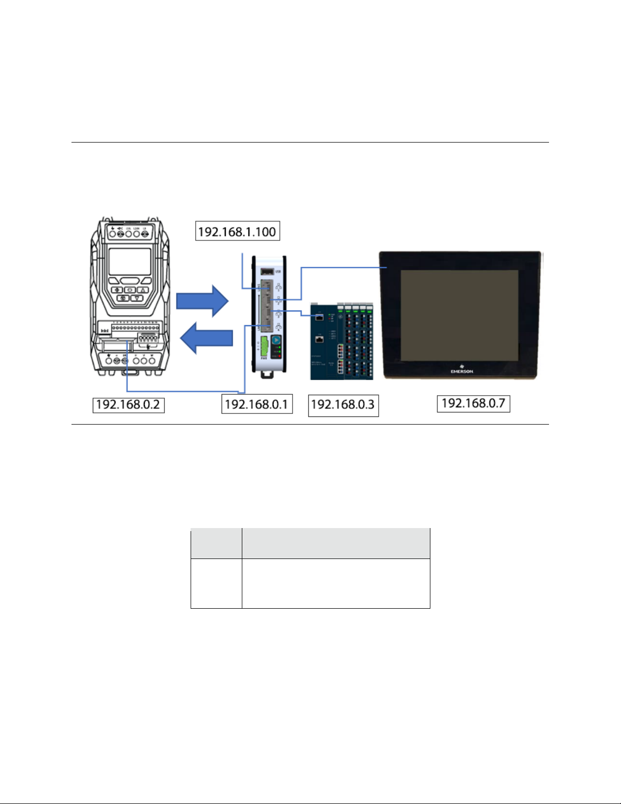
PROFINET Controller Demo (Note 2)
Figure 15: CPE100 (PROFINET Controller) to VFD PROFINET Slave Demo
VFD Settings
1. VFD Parameters must be set to the following values:
For help on changing parameters Refer to Manual GFK-3111.
Parameter
Value and Description
P1-12
P1-14
P5-05
4 (Fieldbus)
201 (Extended parameter description)
0.0 (Disable communication loss timeout)
VFD I/O Signals
Digital
By default, the VFD signals Digital Input 1 (DI1) and Safe Torque Off (STO) must be
energized to allow the VFD to Run. These signals are wired to and powered by the demo
RSTi-EP outputs. The outputs are set automatically when a certain screen is used on the
QuickPanel.
Page 18
PACMotion VFD Syllabus Section 3
GFK-3167A April 2020
CPE100 to VFD PROFINET Demo 14
Analog
The Analog I/O of the RSTi-EP module allow various analog signals to control/monitor the
VFD.
The following is a default map of the I/O points used in the Demo unit:
CPE100
PACMotion VFD
Signal
%Q00001
DI1
Enable Drive
%Q00002
DI2
Reverse
%Q00003
DI3
Set Point 1
%I00001
DI1
Drive Enabled
%AQ00001
AI1
Speed (reference)
%AI00001
AO1
Speed (actual)
24VDC
STO +
Safe Torque +
0VDC
STO -
Safe Torque -
Option Module Details
1. To use PROFINET with the VFD a PROFINET Option Module must be installed.
The PROFINET option card permits the PACMotion VFD Drive to connect to a PROFINET
network.
IC866-OC-P PROFINET Option Card for VFD
PROFINET Option Card
RJ45 Connectors & Network Activity LEDs,
PROFINET Option Card
[1]
LED: NS
[A]
LED: Activity
[2]
RJ45: P1
[B]
LED: Link
[3]
Labeling: PROFINET I/O
[4]
RJ45: P2
[5]
LED: MS
Page 19

PACMotion VFD Syllabus Section 3
GFK-3167A April 2020
CPE100 to VFD PROFINET Demo 15
Bus Specific Technical Data
Baud rate
10/100 Mbaud in full duplex mode
Connection technology
2 × RJ45
Hardware Insertion and Removal
Remove power from the VFD. Using a T9 driver bit, backout the 2 option module screws
approximately 4 or 5 turns each. This should allow the locking tabs to retract to a flat
position. Insert the module into the VFD fieldbus option module cage and gently press it
into place. Secure the T9 screws until they touch the module. This will engage the locking
tabs to hold it in place. Do not over tighten.
(Note: If the T9 screws are not backed out first the module will not insert or remove
properly.)
To remove the option module remove power from the VFD. Using a T9 driver bit backout
the option module 2 screws approximately 4 or 5 turns each. Gently pull the module out
by pulling on the screws.
PROFINET Slave Module Settings
1. With the PROFINET option module installed power up the VFD.
Using the PROFINET DCP tool, which is part of the PAC Machine Edition Utilities, set the
following VFD PROFINET Slave values example:
Device Name
IP Address
vfd-1
192.168.0.2
2. The QuickPanel Plus Ethernet Settings must be set to the following values:
IP address = 192.168.0.7
Subnet mask = 255.255.255.0
Starting the system
3. Connect the VFD PROFINET option module to an available PROFINET port on the
CPE100 (the lower 3 ports) and the QuickPanel to the top ethernet port on the CPE100
and power up the devices.
This is done inside the official PACMotion VFD Demo case.
4. Using a laptop PC with PAC Machine Edition, load in the PAC Machine Edition project:
“VFD_DEMOCASE_PN_Vx” and Download/Run the QuickPanel and CPE100 targets
through the front panel ports labeled “PROFINET/HMI” and “PLC”.
Page 20
PACMotion VFD Syllabus Section 3
GFK-3167A April 2020
CPE100 to VFD PROFINET Demo 16
Supporting Files
Figure 16: VFD Demo Case file
VFD_DEMOCASE_PN_V6.zip
Right-click the icon to Copy the file.
PROFINET Process Data Exchange
The mapping of Process Data Output/Input to Modbus RTU Registers is shown below.
Process Data Word
Typical CPE100 Address
PDO1
%AI00001
PDO2
%AI00002
PDO3
%AI00003
PDO4
%AI00004
PDI1
%AQ00001
PDI2
%AQ00002
PDI3
%AQ00003
PDI4
%AQ00004
Fieldbus Connection Timeout
The VFD interface allows the user to set the “Communication Loss Timeout” and
“Communication Loss Action” values. These parameters are at addresses P5-05 and P5-06
respectively. The Timeout units are 1 = 0.1 sec and the range is from 0.0 (disable) to 5.0
seconds. A setting of 0.0 seconds will allow the VFD to continue running if
communications is lost.
Page 21
PACMotion VFD Syllabus Section 5
GFK-3167A April 2020
Modbus/TCP Demo 17
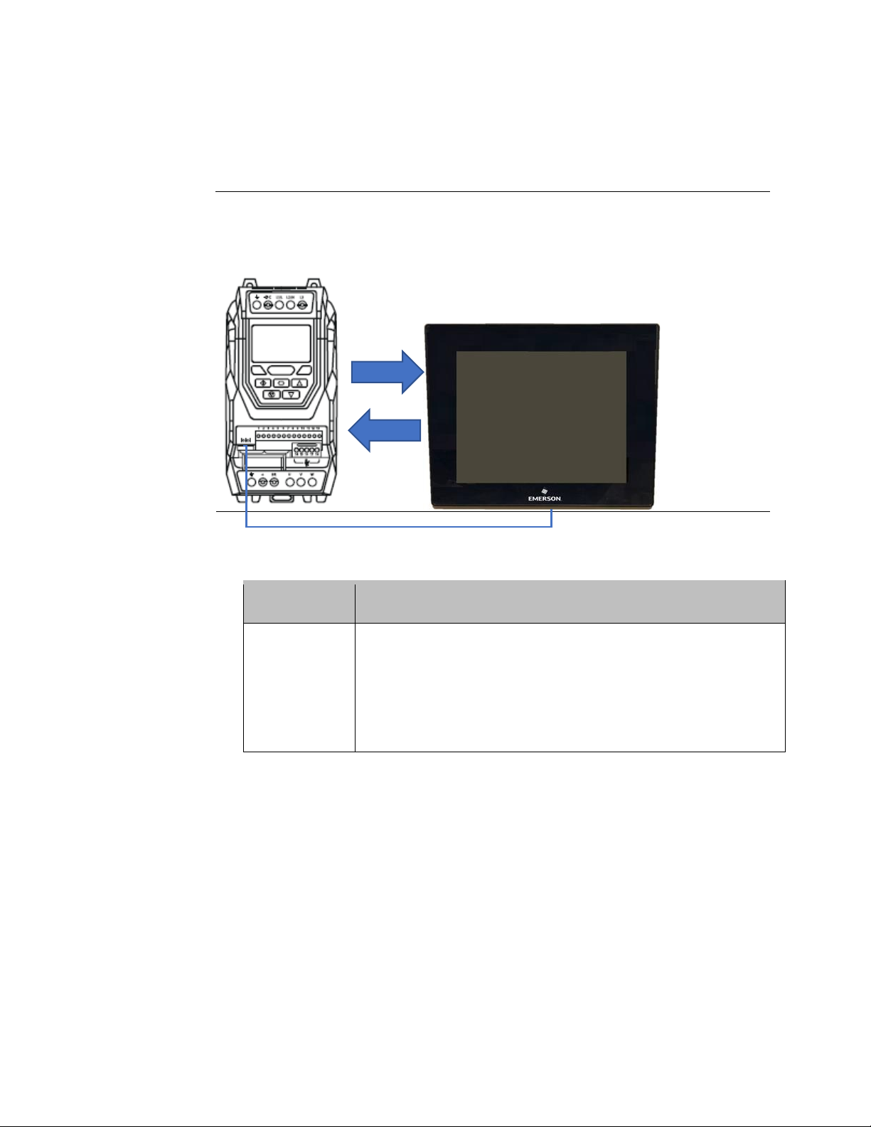
MODBUS RTU SERIAL DEMO (NOTE 3)
Figure 17: Quickpanel Plus or PC w/PME simulator to VFD Built in Serial Port
1. VFD Parameters must be set to the following values:
Parameter
Value and Description
P1-12
P1-14
P5-01
P5-03
P5-04
P5-05
P5-16
4 (Fieldbus)
201 (Extended parameter description)
1 (Fieldbus address)
1 (Modbus RTU Baud rate 19.2Kbps)
0 (Modbus data format, no parity, 1 stop bit)
0.0 (Disable communication loss timeout)
0 (Extended Modbus drive address)
2. QuickPanel Plus with COM2 wiring (the 7 inch QuickPanel Plus does not have a COM2):
Note: To use a 7 inch QuickPanel Plus you would have to add a USB to RS-485/2-wire
serial port.
Page 22
PACMotion VFD Syllabus Section 5
GFK-3167A April 2020
Modbus/TCP Demo 18
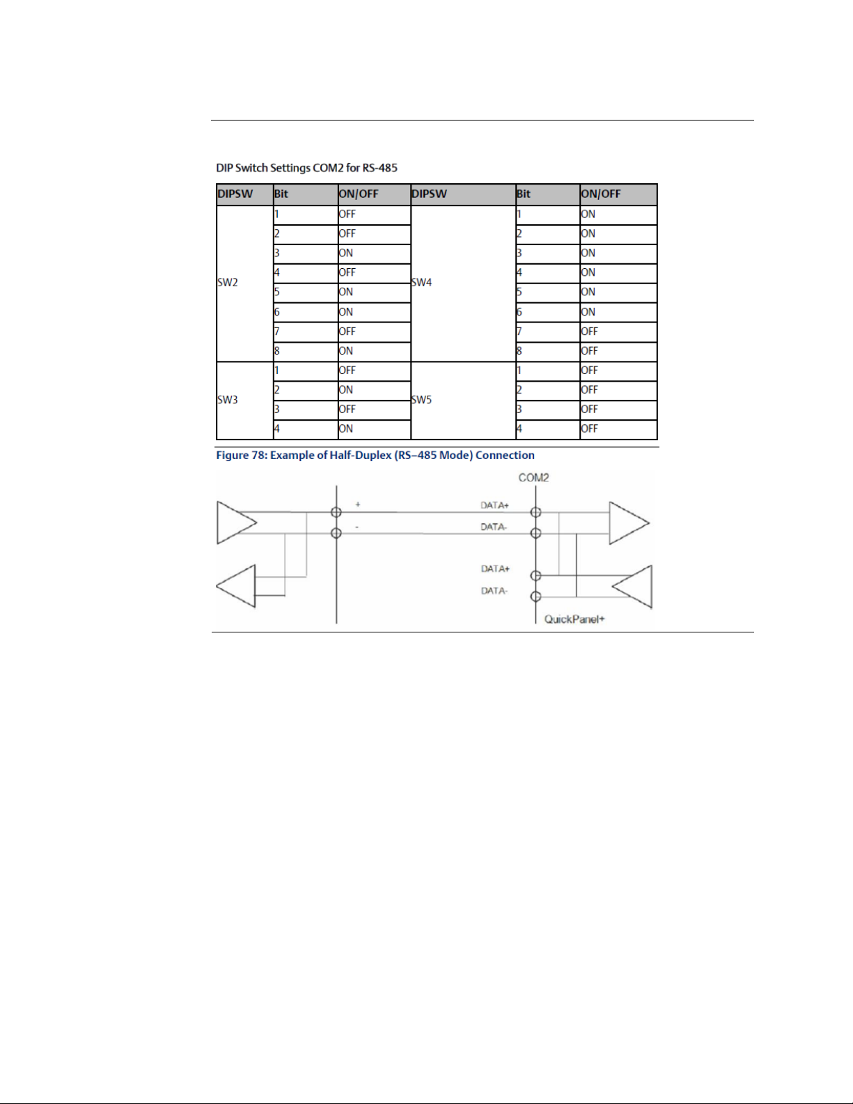
3. Set the QuickPanel Plus DIP switches for RS-485 2 wire operation.
Figure 18: RS-485 2 Wire Operation
Page 23

PACMotion VFD Syllabus Section 5
GFK-3167A April 2020
Modbus/TCP Demo 19
4. VFD to QuickPanel COM2 wiring Serial Cables
Make a serial cable with the following connections. Be sure to jumper the TXD+/RXD+ and
TXD-/RXD- on the QuickPanel for RS-485 two wire operation.
Figure 19: QuickPanel COM2 Port
Page 24

PACMotion VFD Syllabus Section 5
GFK-3167A April 2020
Modbus/TCP Demo 20
5. VFD to Laptop with RS-485 two wiring with a device such as USB Gearmo Model USA:482422
Figure 20: Serial connections PC to VFD
6. Connect the VFD to the Modbus Device and power up the devices.
7. Load in the example PAC Machine Edition project:
“VFD_Modbus_RTU_QPPlus12_VerX” and Download/Run the QuickPanel or the Laptop in
Simulate mode.
8. Set the required VFD terminal discrete signals properly to allow VFD operation.
DI1 = ON (Enabled) and STO = ON (Safe Torque ON)
Supporting Files
Figure19: Modbus RTU Serial Demo file
VFD_Modbus_RTU_QPPlus12_Ver2.zip
Right-click the icon to Copy the file.
Page 25

PACMotion VFD Syllabus Section 5
GFK-3167A April 2020
Modbus/TCP Demo 21
Modbus RTU Process Data Exchange
The mapping of Process Data Output/Input to Modbus RTU Registers is shown below.
Process Data Word
Modbus RTU Register2
PDO1
300001
PDO2
300002
PDO3
300003
PDO4
300004
PDI1
400001
PDI2
400002
PDI3
400003
PDI4
400004
Modbus RTU Connection Timeout
The VFD Modbus RTU interface allows the user to set the “Communication Loss Timeout”
and “Communication Loss Action” values. These parameters are at addresses P5-05 and
P5-06 respectively. The Timeout units are 1 = 0.1 sec and the valid range is from 0.0
(disable) to 5.0 seconds. A setting of 0.0 seconds will allow the VFD to continue running if
communications is lost.
Drive Parameter Access
The Modbus RTU Interface allows the user to read/write the drive parameters. To perform
this function, the user can directly access the parameter. Simply add the parameter
number to the Modbus offset of 400000.
For example:
Read parameter P1-01 (Maximum Frequency), perform the following
Read Modbus RTU Register 400101 value (scaling in 0.1 Hz).
Write parameter P1-01 (Maximum Frequency) = 60.0 Hz, perform the following
Write to Modbus RTU Register 400101 value = 600 (scaling in 0.1 Hz)
2
Modbus Clients may address the first Modbus register as register 300001/400001. This assumes an address offset starting at 1. For
Clients that use zero based addressing just subtract 1.
Page 26

PACMotion VFD Syllabus Section 5
GFK-3167A April 2020
Modbus/TCP Demo 22
MODBUS/TCP DEMO (NOTE 4)
Figure 20: Q
UICKPANEL PLUS OR PC W
/PME
SIMULATOR TO
VFD M
ODBUS
/TCP O
PTION MODULE
This Demo uses the Quick Panel Plus as the Initiating device for Modbus/TCP
communications.
1. VFD Parameters must be set to the following values:
Parameter
Value and Description
P1-12
P1-14
P5-01
P5-05
4 (Fieldbus)
201 (Extended parameter description)
1 (Fieldbus address)
0.0 (Disable communication loss timeout)
2. QuickPanel Plus Ethernet Settings
Set the following IP Address/Mask:
IP address = 192.168.1.7
Subnet mask = 255.255.255.0
3. VFD Modbus/TCP Option Module settings
Use a DHCP server or the HMS IPConfig software to set the IP address of the Modbus/TCP
module. Use the following settings:
IP address = 192.168.1.5
Subnet mask = 255.255.255.0
4. Connect the VFD to the Modbus/TCP Device and power up the devices.
192.168.1.
192.168.1.
Page 27

PACMotion VFD Syllabus Section 5
GFK-3167A April 2020
Modbus/TCP Demo 23
5. Load in the example PAC Machine Edition project:
“VFD_ModbusTCP_QPPlus12_VerX” and Download/Run the QuickPanel or the Laptop in
Simulate mode.
6. Set the required VFD terminal discrete signals properly to allow VFD operation.
DI1 = ON (Enabled) and STO = ON (Safe Torque ON)
Supporting Files
Figure 21: VFD Modbus TCP
VFD_ModbusTCP_QPPlus12_Ver2.zip
Right-click the icon to Copy the file.
Modbus/TCP Process Data Exchange
The mapping of Process Data Output/Input to Modbus/TCP Registers is shown below.
Process Data Word
Modbus RTU Register3
PDO1
300001
PDO2
300002
PDO3
300003
PDO4
300004
PDI1
400001
PDI2
400002
PDI3
400003
PDI4
400004
Modbus/TCP Connection Timeout
The VFD Fieldbus interface allows the user to set the “Communication Loss Timeout” and
“Communication Loss Action” values. These parameters are at addresses P5-05 and P5-06
respectively. The Timeout units are 1 = 0.1 sec and the valid range is from 0.0 (disable) to
5.0 seconds. A setting of 0.0 seconds will allow the VFD to continue running if
communications is lost.
3
Modbus/TCP Clients may address the first Modbus/TCP register as register 300001/400001. This assumes an address offset starting at
1. For Clients that use zero based addressing just subtract 1.
Page 28

PACMotion VFD Syllabus Section 5
GFK-3167A April 2020
Modbus/TCP Demo 24
Drive Parameter Access
The Modbus/TCP Interface allows the user to read/write the drive parameters. To perform
this function, the user can directly access the parameter. Simply add the parameter
number to the Modbus/TCP offset of 400000.
For example:
Read parameter P1-01 (Maximum Frequency), perform the following
Read Modbus/TCP Register 400101 value (scaling in 0.1 Hz).
Write parameter P1-01 (Maximum Frequency) = 60.0 Hz, perform the following
Write to Modbus/TCP Register 400101 value = 600 (scaling in 0.1 Hz)
Page 29

PACMotion VFD Syllabus Section 5
GFK-3167A April 2020
Modbus/TCP Demo 25
USER DEFINED FUNCTION BLOCK – MODBUS/TCP
(NOTE 5)
Figure 22: For Use with PACMotion VFD Modbus/TCP Option Module
1. Install the Modbus/TCP Option Module in your VFD.
Typical Part number IC866-OC-M.
2. The proper IP addresses must be set for your devices to communicate.
CPE100 = 192.168.1.100 (set with Proficy Machine Edition (PME)
VFD = 192.168.1.5 (set with a DHCP Server or IPCONFIG Tool from Anybus.Com)
3. Import the UDFB into PME.
The UDFB named “VFD_MBTCP” can be added to your PME project with the “Import Drawer”
function of the Toolchest, or the “Import Block From File” function of the Navigator Program Blocks.
Below is an example of the Navigator Import Block from File:
Figure 23: Import Block from File
PDI1 - 4
Page 30

PACMotion VFD Syllabus Section 5
GFK-3167A April 2020
Modbus/TCP Demo 26
Choose the XML file named “VFD_MBTCP.XML”
Figure 24: Select the XML File
4. Using the UDFB in your Logic.
Insert a CALL statement in your Logic and Double-Click on the CALL and choose the UDFB
“VFD_MBTCP”.
Figure 25: Insert a Call Statement
5. Assign the UDFB Instance name in your Logic.
You must assign an Instance name that is unique to the UDFB. Position the cursor on the block and
type in the Instance name where the question marks are.
Figure 26: Assign an Instance Name
Page 31

PACMotion VFD Syllabus Section 5
GFK-3167A April 2020
Modbus/TCP Demo 27
6. This Instance will have created a Structure with all variables needed for the PNS.
The Instance “VFD1” name is shown as an example below:
Figure 27: Instance Has Been Created
The Structure of points used in the Instance of this UDFB shown below:
Figure 28: Structure of Points used in Instance
Page 32

PACMotion VFD Syllabus Section 5
GFK-3167A April 2020
Modbus/TCP Demo 28
7. Assign input and output node variables.
This UDFB is an example of how the Modbus/TCP functions of the VFD can be controlled/monitored.
Each Instance of the UDFB must have a different and unique Instance Name (VFD1 below). Various
node names are given to reflect the function they represent.
Figure 29: Assign Input and Output Node Variables
Page 33

PACMotion VFD Syllabus Section 5
GFK-3167A April 2020
Modbus/TCP Demo 29
8. Starting the system
Be sure to set your VFD Parameter P1-12 to 4 for Fieldbus Control.
Download the project to your PACSystems Controller.
Connect the top Ethernet Port of the CPE100 to the VFD Modbus/TCP option module. Power up the
devices and test functionality.
9. Setting Fieldbus Connection Timeout Preferences
The VFD interface allows the user to set the “Communication Loss Timeout” and “Communication
Loss Action” values. These parameters are at addresses P5-05 and P5-06 respectively. The Timeout
units are 1 = 0.1 sec and the range is from 0.0 (disable) to 5.0 seconds. Set these appropriately. A
setting of 0.0 seconds will allow the VFD to continue running if communications is lost.
Page 34

PACMotion VFD Syllabus Section 7
GFK-3167A April 2020
User Defined Function Block UDFB 30
USER DEFINED FUNCTION BLOCK – PROFINET
(NOTE 6)
Figure 30: For Use with PACMotion VFD PROFINET Option Module
1. Install the PROFINET Slave Option Module in your VFD.
Typical Part number IC866-OC-P.
2. The proper GSDML file for this device must be added to your PROFINET Controller in
PAC Machine Edition (PME). The VFD will become a PROFINET Slave (PNS).
Typical file name: GSDML-V2.31-Intelligent Platforms, LLC-PACmotionVFD-
20200113.xml
Page 35

PACMotion VFD Syllabus Section 7
GFK-3167A April 2020
User Defined Function Block UDFB 31
3. The unique PROFINET Name and IP address should be set for each PNS.
Be sure your IP address is in the PROFINET Controller (PNC) range and to assign a
Reference Variable to each (PNS & PNC) for PNIO_DEV_COMM use later, typical PNS
settings are shown below:
Figure 31: PNS Settings
4. The PNS will have 4 slots autoconfigured:
Slots 1,2,3 must be addressed. Double-click on the slots and configure them.
Figure 32: Configured Slots
Page 36

PACMotion VFD Syllabus Section 7
GFK-3167A April 2020
User Defined Function Block UDFB 32
5. PROFINET PNS Configuration in PME:
3 address ranges must be entered for the PNS with similar values to the example
below:
• %AQ00001 Length 4 Words (slot 1)
• %AI00001 Length 4 Words (slot 2)
• %AI00005 Length 4 Words (slot 3)
Figure 33: PROFINET PNS Configurations
Page 37

PACMotion VFD Syllabus Section 7
GFK-3167A April 2020
User Defined Function Block UDFB 33
6. Import the UDFB into PME.
The UDFB named “VFD_PNS” can be added to your PME project with the “Import Drawer”
function of the Toolchest, or the “Import Block From File” function of the Navigator
Program Blocks. Below is an example of the Navigator Import Block from File:
Figure 34: Import the UDFB into PME
7. Choose the XML file named “VFD_PNS.XML”.
Figure 35: Choose the XML File
8. Using the UDFB in your Logic.
Insert a CALL statement in your Logic and Double-Click on the CALL and choose the
UDFB “VFD_PNS”.
Figure 36: UDFB Logic
Page 38

PACMotion VFD Syllabus Section 7
GFK-3167A April 2020
User Defined Function Block UDFB 34
9. Assign the UDFB Instance name in your Logic.
You must assign an Instance name that is unique to the UDFB. Position the cursor on
the block and type in the Instance name where the question marks are.
Figure 37: Assigning Instance Name
10. This Instance will have created a Structure with all variables needed for the PNS.
The Instance “VFD_Inst1” name is shown as an example below:
Figure 38: Instance-Created Structure
Page 39

PACMotion VFD Syllabus Section 7
GFK-3167A April 2020
User Defined Function Block UDFB 35
11. The Structure of points used in the Instance of this UDFB shown below:
Figure 39: Structure of Points in Instance
Page 40

PACMotion VFD Syllabus Section 7
GFK-3167A April 2020
User Defined Function Block UDFB 36
12. Assign input and output node variables.
This UDFB is an example of how the PROFINET functions of the VFD can be
controlled/monitored. Each Instance of the UDFB must have a different and unique
Instance Name (VFD1 below). Various node names are given to reflect the function they
represent.
Figure 40: Assign IO Node Variables
Page 41

PACMotion VFD Syllabus Section 7
GFK-3167A April 2020
User Defined Function Block UDFB 37
13. Starting the system
Be sure to set your VFD Parameter P1-12 to 4 for Fieldbus Control. You may wish to insert a
PNIO_DEV_COMM block (similar to below) to assure your PROFINET Controller and PNS
are communicating without issue. The Reference Variables names created in step 3 can be
used for the PNIO_DEV_COMM. The output of the PNIO_DEV_COMM can be used to
power the UDFB.
Figure 41: Check the Status of the PNS Connection
14. Download the project to your PACSystems Controller.
Connect the PROFINET Controller to the VFD PROFINET option module. Power up the
devices and test functionality.
Setting Fieldbus Connection Timeout Preferences
The VFD interface allows the user to set the “Communication Loss Timeout” and
“Communication Loss Action” values. These parameters are at addresses P5-05 and P5-06
respectively. The Timeout units are 1 = 0.1 sec and the range is from 0.0 (disable) to 5.0
seconds. Set these appropriately. A setting of 0.0 seconds will allow the VFD to continue
running if communications is lost.
Page 42

PACMotion VFD Syllabus Section 7
GFK-3167A April 2020
User Defined Function Block UDFB 38
PROFINET Process Data Exchange Map
The typical mapping of VFD Process Data Output (PDO)/Process Data Input (PDI) to
PROFINET Slave Addresses is shown below.
Process Data Word
Typical CPE Address
PDO1
%AI00001
PDO2
%AI00002
PDO3
%AI00003
PDO4
%AI00004
Additional Word 5
%AI00005
Additional Word 6
%AI00006
Additional Word 7
%AI00007
Additional Word 8
%AI00008
PDI1
%AQ00001
PDI2
%AQ00002
PDI3
%AQ00003
PDI4
%AQ00004
Page 43

PACMotion VFD Syllabus Section 7
GFK-3167A April 2020
User Defined Function Block UDFB 39
Supporting Files
Figure 42: VFD UDFB
VFD_CPE100_PN_UDFB.zip
Right-click the icon to Copy the file.
Figure 43: PROFINET UDFB to VFD Toolchest:
VF D_UDFBs.ZDRW
This Drawer also contains Modbus/TCP UDFB blocks)
Right-click the icon to Copy the file.
Figure 44: PROFINET UDFB to VFD XML Block Code
VFD_PNS.xml
Right-click the icon to Copy the file.
Page 44

PACMotion VFD Syllabus Section 6
GFK-3167A April 2020
User Defined Function Block UDFB 40
Other Modbus/TCP UDFBs
These UDFBs can be used similarly to the above UDFB. Nodes will change based on the
function.
VFD_RD_PARM
Used to Read 1 Parameter from the VFD.
VFD_WR_PARM
Used to Write 1 Parameter to the VFD.
VFD_RD_G1
Used to Read all Group 1 Parameters from the VFD.
Supporting Files
Modbus/TCP UDFB to VFD PME Projects
Figure 45: VFD PME Projects with Modbus/TCP UDFB
VFD_MBTCP_UDFB_V1.zip
VFD_MBTCP_UDFB_WR_PARM_V1.zip
VFD_MBTCP_UDFB_RD_PARM_V1.zip
VFD_MBTCP_UDFB_RD_G1_V1.zip
Right-click the icon to Copy the file.
Page 45

PACMotion VFD Syllabus Section 6
GFK-3167A April 2020
User Defined Function Block UDFB 41
Modbus/TCP UDFB to VFD Toolchest Drawer
(This Drawer also contains PROFINET UDFB blocks)
Figure 46:VFD Toolchest Drawer with Modbus/TCP UDFB
VF D_U DFBs.ZDRW
Right-click the icon to Copy the file.
Modbus/TCP UDFB to VFD XML Block Code
Figure 47: VFD XML Block Code for Modbus/TCP UDFBs
VFD_MBTCP.xml
VFD_RD_PARM.xml
VFD_WR_PARM.xml
VFD_RD_G1.xml
Right-click the icon to Copy the file.
Page 46

PACMotion VFD Syllabus Section 7
GFK-3167A April 2020
Bluetooth USB and Serial Cable 42
BLUETOOTH USB AND SERIAL CABLE (NOTE 7)
Communications to the VFD
Bluetooth BLE Connection
You can use the internal (built in) or external (USB) type Bluetooth BLE ports for your PC.
1. On the VFD plug the Bluetooth BLE USB Stick (typical part number IC866-BLUE) into the
Serial port (not the RJ-45 LAN network port) and turn on power to the VFD.
After a few seconds you should see the green, red, and blue LEDs similar to the picture
below:
Figure 48: Bluetooth BLE USB Stick
2. Start the Emerson PACMotion VFD Studio program.
3. Go to Tools-Select Communications Device menu.
4. Select the connection type = BluetoothStick (BLE).
Page 47

PACMotion VFD Syllabus Section 7
GFK-3167A April 2020
Bluetooth USB and Serial Cable 43
5. Select the BLE Interface = Integrated Bluetooth LE.
• This will be the typical built-in “Integrated Bluetooth LE” Bluetooth of your laptop.
Figure 49: Communication Settings
6. If you need to install an external Bluetooth device such as Bluetooth BLE USB Dongle be
sure to use a “BLE” (Bluetooth Low Energy) device. A regular Bluetooth device will not
work. One BLE tested device would be a BlueGiga part number BLED112-V1. When the
driver for this USB device is installed it should be assigned to an available COM port and be
selectable as seen below:
Figure 50: BLE Option
Page 48

PACMotion VFD Syllabus Section 7
GFK-3167A April 2020
Bluetooth USB and Serial Cable 44
7. Click the Scan button.
You should see the VFD “BluetoothStick” USB device in the list such as below:
Figure 51: VFD BlutoothStick Displayed in List
8. Click the small box to Select the VFD BluetoothStick device for connection.
9. Click the Connect button to connect to the Bluetooth Device.
10. Click the “Scan Drive Network” button (Allow a few seconds for the scan to complete).
This should find the VFD and transfer parameters from the VFD to the Studio.
In factory default mode you will only see Group 1 Tab with parameters (rows) for the VFD.
Figure 52: Group 1 Tab
11. Click on the variable number in the “Value” Column for P1-14 Extended Menu Access
Code.
12. Change the value to 201 and then press enter to accept the value.
You should see more Parameter tabs now (Group 0 to Group 9).
Page 49

PACMotion VFD Syllabus Section 7
GFK-3167A April 2020
Bluetooth USB and Serial Cable 45
Figure 53: Parameter Tabs
13. Save these parameters to your PC for future use by clicking “File-Save Parameter Set As….”
14. Press and hold the Red Lock button on the USB for aprox 3 seconds (until the yellow LEDs
stop flashing).
This will unlock the USB.
After a few seconds you should see the green, (no red), and blue LEDs similar to the picture
below:
Figure 54: Bluetooth BLE LEDs
Notice on the USB the 2 Green arrows (R/W) appear and the Red Lock disappears.
15. Select Parameters-Transfer Parameter Set to Drive
Allow a few seconds for the data to finish transferring from PC to VFD.
On the VFD Display you will see: “Parameters Written Successfully” for a few seconds.
This is how you would restore parameters in the VFD.
VFD Faceplate Parameter Access
Page 50

PACMotion VFD Syllabus Section 7
GFK-3167A April 2020
Bluetooth USB and Serial Cable 46
16. Call up the VFD Parameter list with the VFD keypad.
Press and hold the Navigate key > 2 seconds.
Figure 55: Navigate Key
You should see the parameters on the VFD faceplate display.
You can press the up and down Arrow Buttons to look at the various parameters.
Press the Navigate key once quickly to see the value of the parameter selected.
VFD Suite Real-Time Edit and Drive Monitor Tool
17. Click Real-Time Edit Mode button to enable Real-Time mode.
18. Scroll down to the Parameter P0-65 “Drive Life Time” row and select the box in the Refresh
Column.
You should see dynamic data updating in the Value Column.
19. Choose File-Save Parameter Set as your backup copy of the Real-Time parameters.
To select the Drive Monitor Tool, you must briefly leave the Real-Time Edit mode.
20. Click Disable Real-Time Edit.
21. Click Tools-Drive Monitor Tool.
22. Click the Enable Real-Time Monitor button.
23. In the “Local” column select the box for the VFD on your list.
You should see Live data on the Monitor Screen.
Figure 56: Local Column
24. Start the Drive by pressing the green “Start The Motor” button (motor will RUN if
permissives are true).
25. Enter a “Target Motor Speed” to Run the Drive.
26. Press the button again to Reverse the Motor.
27. Stop the Motor when finished.
Page 51

PACMotion VFD Syllabus Section 7
GFK-3167A April 2020
Bluetooth USB and Serial Cable 47
28. Disable the Real-Time Monitor when finished.
VFD Real-Time Edit and Drive Monitor Tool
To use the Scope and Data Logging Tool you must leave the Real-Time Edit mode.
29. Click Disable Real-Time Edit.
30. Click Tools-Scope/Data Logger
Figure 57: Scope/Data Logger
31. Choose the Channel 1 and 2 data similar to below and then Click the START Button to
Capture Data.
(Fieldbus Speed Ref (Hz) and Master Speed Ref (Hz))
32. Click the STOP Button to stop the capture.
33. Choose File-Save Scope Data to keep the Captured information.
This can also be saved as a CSV file type for analysis.
Page 52

PACMotion VFD Syllabus Section 8
GFK-3167A April 2020
Serial RS-485 Communication to the VFD 48
Serial RS-485 Communications to the VFD
1. Make sure your PC supports an open USB port and plug in the USB-to-Serial device
(typical part number IC855-CABL-USB485).
This is wired to connect to the Optibus pins (4 and 5) of the VFD serial.
Figure 58: USB-to-Serial Devices
Your PC should recognize the USB device and assign a COM port.
Page 53

PACMotion VFD Syllabus Section 8
GFK-3167A April 2020
Serial RS-485 Communication to the VFD 49
2. Click Tools – Select Communications Device.
Figure 59: Select Communication Device
3. Choose the “Wired Serial Interface (RS485/RS232)” and the appropriate COMx port
number.
Figure 60: Connection Type
4. Click the “Connect” Button.
You should be able to Scan the Drive Network now and perform any of the functions in the
above document as you did with the Bluetooth USB device.
Supporting Files
Figure 61: VFD Demo Case
VFD_S2_230V_0.75k
W_V2.50_DemoCase.ptl
Right-click the icon to Copy the file.
Page 54

PACMotion VFD Syllabus Section 9
GFK-3167A April 2020
PACMotion VFD Fieldbus Option Modules/Setup 50
PACMotion VFD Fieldbus Option Modules and Setup (NOTE 8)
MODBUS/TCP FIELDBUS OPTION MODULE
Option
Module
IC866OC-M
Modbus TCP Option
Card for VFD
The Modbus/TCP option card permits the PACMotion Drive to connect to a Modbus/TCP
network.
Figure 62: Modbus/TCP Option Card
Figure 63: RJ45 Connectors &
Network Activity LEDs,
Modbus/TCP Option Card
[1]
LED: NS
[A]
LED: Activity
[2]
RJ45: P1
[B]
LED: Link
[3]
Labeling: Modbus/TCP
[4]
RJ45: P2
[5]
LED: MS
Bus Specific Technical Data
Baud rate
10/100 Mbaud in full duplex mode
Connection technology
2 × RJ45
Page 55

PACMotion VFD Syllabus Section 9
GFK-3167A April 2020
PACMotion VFD Fieldbus Option Modules/Setup 51
Hardware Insertion and Removal
Remove power from the VFD. Using a T09 driver bit, backout the option module 2 screws
approximately 4 or 5 turns each. This should allow the locking tabs to retract to a flat
position. Insert the module into the VFD fieldbus option module cage and gently press it
into place. Secure the T09 screws until they touch the module. . This will engage the
locking tabs to hold it in place. Do not over tighten .
Note: If the T09 screws are not backed out first the module will not insert/remove
properly.
To remove the option module remove power from the VFD. Using a T09 driver bit backout
the option module 2 screws approximately 4 or 5 turns each. Gently pull the module out
by pulling on teh 2 screws.
IP Address Setup
The IP address of the Modbus/TCP module is set with a DHCP Server or with the
IPCONFIGTOOL software from Anybus.
Start-Up and Operation
Modbus/TCP
Parameter setting
P1-12 = 4 (Fieldbus)
P1-14 = 101 (Extended parameter description)
IP address
The basic setting of the option card is the DHC protocol. To establish
communication with the network, set the IP address using the
"Anybus IPconfig" software. The freeware is available at
www.anybus.com.
Bus structure
You can use the integrated Ethernet switch to achieve line topologies
known from the fieldbus technology. Other bus topologies, such as
star or tree, are also possible. Ring topologies are not supported.
LEDs
The Modbus/TCP option card has two LEDs, designated per Figure 62 as:
• NS for Network Status and
• MS for Module Status.
Page 56

PACMotion VFD Syllabus Section 9
GFK-3167A April 2020
PACMotion VFD Fieldbus Option Modules/Setup 52
Network Status LED
Status
Explanation
Off
No supply voltage available.
Lights up green
Connection established, communication available.
Flashing green
Connection established, communication not available.
Lights up red
IP address is set to 0.0.0.0.
Flashing red
Communication timeout.
Module Status LED
Status
Explanation
Off
No supply voltage available.
Lights up green
Ethernet connection established, communication not
available.
Lights up red
Option card fault.
Flashing red
IP conflict.
Modbus TCP Data Exchange
Modbus TCP process data is exchange utilizing the same format as described in section
9.1.1 Structure and Settings of Process Data Words. The mapping to Modbus TCP
Registers is shown below.
Reference Word
Modbus TCP Register4
PO1
300001
PO2
300002
PO3
300003
PO4
300004
PI1
400001
PI2
400002
PI3
400003
PI4
400004
4
Modbus Clients may address the first Modbus register as register 300001/400001. This assumes an address offset starting at 1. For
Clients that use zero based addressing just subtract 1.
Page 57

PACMotion VFD Syllabus Section 9
GFK-3167A April 2020
PACMotion VFD Fieldbus Option Modules/Setup 53
Modbus TCP Connection Timeout
The VFD Modbus TCP interface allows the user to set the “Communication Loss Timeout”
and “Communication Loss Action” values. These parameters are at addresses P5-05 and
P5-06 respectively. The Timeout units are 1 = 0.1 sec and the range is from 0.0 (disable) to
5.0 seconds.
Drive Parameter Access – Direct Address Method
The Modbus Interface allows the user to read/write directly the drive parameters. To
perform this function, the user can directly access the parameter. Simply add the 3-digit
parameter number to the Modbus offset of 400000.
For example:
Read parameter P1-01 (Maximum Frequency), perform the following
Read Modbus TCP Register 400101 value (scaling in 0.1 Hz).
Write parameter P1-01 (Maximum Frequency) = 60.0 Hz, perform the following
Write to Modbus TCP Register 400101 value = 600 (scaling in 0.1 Hz)
Drive Parameter Access – Indirect Address Method
The Modbus Interface allows the user to read/write indirectly the drive parameters. To do
this you must use an Index number (Pointer) to point to the Parameter (Value) you want to
access. The Index is at Modbus Address 404131. You must also use the next address
404132 to Read or Write the data desired.
EXAMPLE: Given that the Index pointer = Addr. 404131 and Index Value = Addr. 404132
Read parameter P1-01 (Maximum Speed), perform the following:
Write to Modbus TCP Register 404131 a value = 101 <- Code for P1-01 (reference table)
*Read from Modbus TCP Register 404132 value = Parameter Value in P1-01
*P2-39 Lock/Unlock = will not affect this R/W of Parameters
To Write to P1-01 01 (Maximum Speed) and set it to 1800 rpm, perform the following:
Write to Modbus TCP Register 404131 value = 101 (This moves P1-01 current value into
404132)
**Write to Modbus TCP Register 404132 with the New value = 3600 (scaling in .5 rpm)
eg. 6 = 0.1Hz
**P1-12 must be = 4 for Write capability into a Parameter. This could be done on the VFD
faceplate or with the PACMotion VFD Suite.
Page 58

PACMotion VFD Syllabus Section 9
GFK-3167A April 2020
PACMotion VFD Fieldbus Option Modules/Setup 54
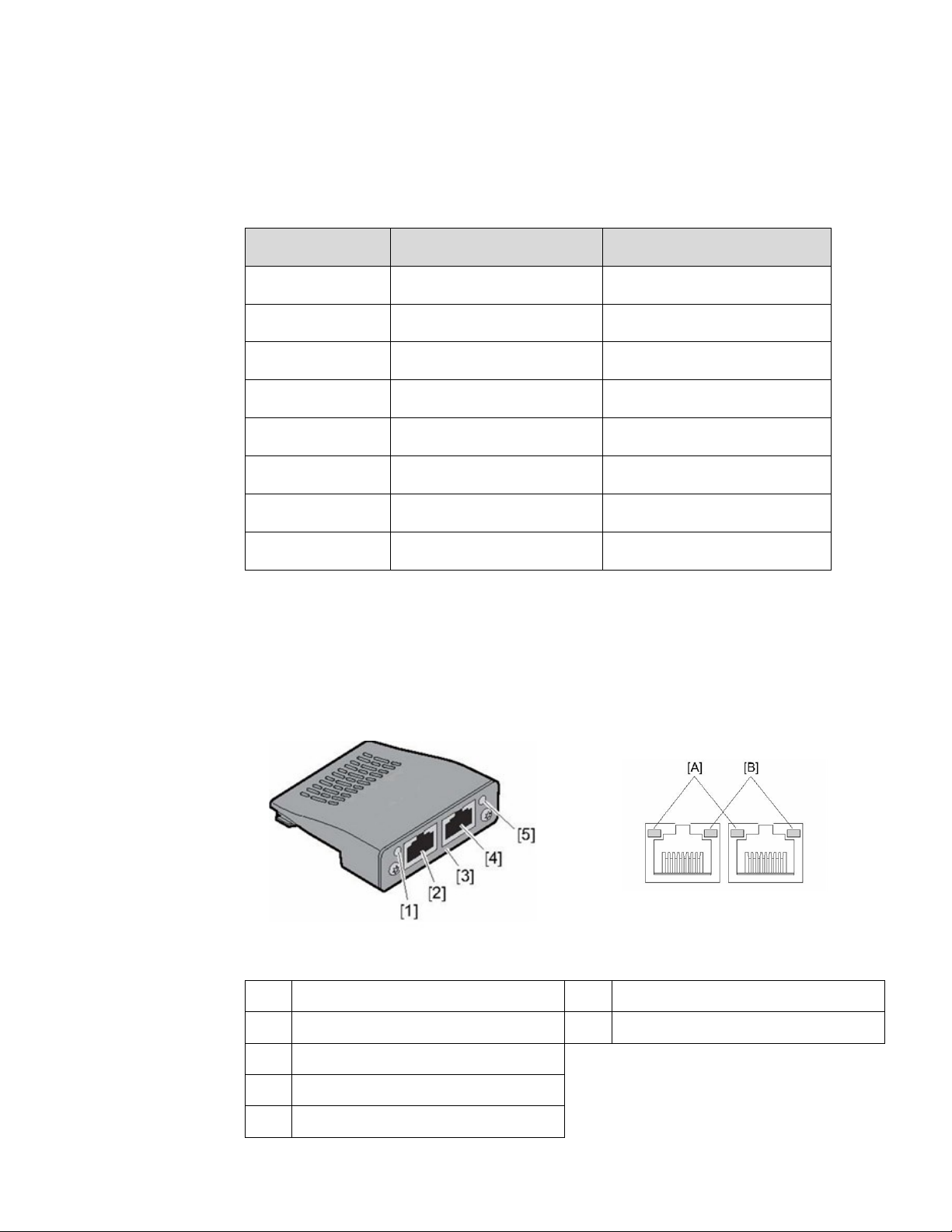
PROFINET FIELDBUS OPTION MODULE
Option Module Details: PROFINET Option Card for VFD Part Number: IC866-OC-P
The PROFINET option card permits the PACMotion VFD Drive to connect to a PROFINET
network.
PROFINET Option Card
RJ45 Connectors & Network
Activity LEDs, PROFINET Option
Card
[1]
LED: NS
[A]
LED: Activity
[2]
RJ45: P1
[B]
LED: Link
[3]
Labeling: PROFINET I/O
[4]
RJ45: P2
[5]
LED: MS
Bus Specific Technical Data
Baud rate
10/100 Mbaud in full duplex mode
Connection technology
2 × RJ45
Page 59

PACMotion VFD Syllabus Section 9
GFK-3167A April 2020
PACMotion VFD Fieldbus Option Modules/Setup 55
Hardware Insertion and Removal
Remove power from the VFD. Using a T09 driver bit, backout the option module 2 screws
approximately 4 or 5 turns each. This should allow the locking tabs to retract to a flat
position. Insert the module into the VFD fieldbus option module cage and gently press it
into place. Secure the T09 screws until they touch the module. This will engage the locking
tabs to hold it in place. Do not over tighten.
Note: If the T09 screws are not backed out first the module will not insert/remove
properly.
To remove the option module remove power from the VFD. Using a T09 driver bit backout
the option module 2 screws approximately 4 or 5 turns each. Gently pull the module out.
Page 60

PACMotion VFD Syllabus Section 10
GFK-3167A April 2020
PDO/PDI Data Map and Addressing Modbus/TCP PDO Data 56
PDO/PDI Data Map and Addressing (Note 9)
VFD Process Data Output (PDO1 - 4) From VFD to Client (Master)
The Client will initiate communications and READ this data from the VFD.
Figure 64: Modbus/TCP Client (Master)
Modbus/TCP PDO Data (or Built-in Modbus RTU Serial Port)
PDO1 (Drive Status Word - Fixed)
Modbus/TCP address: 300001
Bit 0
0 = Drive Disabled (Stopped), 1 = Drive Enabled (Running)
Bit 1
0 = Drive Healthy, 1 = Drive Tripped
Bit 2
No Function
Bit 3
0 = Drive Ready (STO Closed), 1 = Drive Inhibit (STO Open)
Bit 4
0 = Maintenance Time Not Reached, 1 = Maintenance Time Reached
Bit 5
0 = Not in Standby (Sleep), 1 = Standby (Sleep) mode Active
Bit 6
0 = Drive Not Ready, 1 = Drive Ready (Mains Power Applied, No Inhibit,
No Trip, Enable Input Present)
Bit 7
No Function
Bits 8-15
Fault Number in the event of a Drive Trip
Page 61

PACMotion VFD Syllabus Section 10
GFK-3167A April 2020
PDO/PDI Data Map and Addressing Modbus/TCP PDO Data 57
PDO2 (Output Frequency - Fixed)
Modbus/TCP address: 300002
123 = 12.3 Hz
PDO3 (Output Current or P5-12 select)
Modbus/TCP address: 300003
105 = 10.5 A
PDO4 (Output Torque or P5-08 select)
Modbus/TCP address: 300004
33 = 3.3 %
Modbus/TCP or RTU PDI Data
VFD Process Data Input (PDI1 - 4) From Client (Master) To Server (Slave)
The Client will initiate communications and WRITE this data to the VFD.
Figure 65: Modbus/TCP Client (Master)
PDI1 (Drive Control Word)
Modbus/TCP address: 400001
Bit 0
0 = Stop the Drive (Disable), 1 = Run the Drive (Enable)
Bit 1
0 = Allow Drive to Run, 1 = Enable Drive to Stop with 2nd deceleration ramp
(Fast stop request.)
Bit 2
0 = No Fault Reset, 1 = reset any active faults or trips on the drive (Reset
request).
This bit must be reset to zero once the fault has been cleared.
Bit 3
0 = Allow Drive to Run. Set to 1 to issue a coast stop command (Coast stop
request).
Bit 4-7
No Function
Page 62

PACMotion VFD Syllabus Section 10
GFK-3167A April 2020
PDO/PDI Data Map and Addressing Modbus/TCP PDO Data 58
PDI2 (Frequency Reference)
Modbus/TCP address: 400002
500 = 50.0Hz
PDI3 (Torque Reference or P5-14 select)
Modbus/TCP address: 400003
1000 = 100.0%
PDI4 (Fieldbus Ramp or P5-13 to select, P5-07 to Enable)
Modbus/TCP address: 400004
60000 = 600.00s
Page 63

PACMotion VFD Syllabus Section 10
GFK-3167A April 2020
PDO/PDI Data Map and Addressing Modbus/TCP PDO Data 59
PROFINET PDO Data
VFD Process Data Output (PDO1 - 4) From VFD to PROFINET Controller
The PROFINET Controller will RECEIVE this data from the VFD.
Figure 66: PROFINET PDO Data
PDO1 (Drive Status Word - Fixed)
PROFINET Slave assigned address: %AI00001 (Typical)
PDO2 (Output Frequency - Fixed)
PROFINET Slave assigned address: %AI00002 (Typical)
123 = 12.3 Hz
PDO3 (Output Current or P5-12 select)
Bit 0
0 = Drive Disabled (Stopped), 1 = Drive Enabled (Running)
Bit 1
0 = Drive Healthy, 1 = Drive Tripped
Bit 2
No Function
Bit 3
0 = Drive Ready (STO Closed), 1 = Drive Inhibit (STO Open)
Bit 4
0 = Maintenance Time Not Reached, 1 = Maintenance Time Reached
Bit 5
0 = Not in Standby (Sleep), 1 = Standby (Sleep) mode Active
Bit 6
0 = Drive Not Ready, 1 = Drive Ready (Mains Power Applied, No Inhibit, No Trip, Enable Input
Present)
Bit 7
No Function
Bits 8-15
Fault Number in the event of a Drive Trip
Page 64

PACMotion VFD Syllabus Section 10
GFK-3167A April 2020
PDO/PDI Data Map and Addressing Modbus/TCP PDO Data 60
PROFINET Slave assigned address: %AI00003 (Typical)
105 = 10.5 A
PDO4 (Output Torque or P5-08 select)
PROFINET Slave assigned address: %AI00004 (Typical)
33 = 3.3 %
VFD Data Output (PDO5 - 8) From VFD to PROFINET Controller – Additional to PDO
PROFINET Slave assigned address: WORD 5 = %AI00005 (Typical)
PROFINET Slave assigned address: WORD 6 = %AI00006 (Typical)
PROFINET Slave assigned address: WORD 7 = %AI00007 (Typical)
Not Defined
Bit 0
1 = Module OK (drive Healthy No Trip)
Bit 1
0 = Drive Healthy, 1 = Fault Present, Drive Tripped
Bit 2
0 = Port 1 Link Down, 1 = Port 1 Link Up
Bit 3
0 = Port 2 Link Down, 1 = Port 2 Link Up
Bit 4
Not Defined
Bit 5
Not Defined
Bit 6
Not Defined
Bit 7
Not Defined
Bit 8
0 = Mains Power Loss (“ML” indication), 1 = Mains power OK
Bit 9
1 = 24 V backup (external 24 V mode)
Bit 10
MRP enabled (fixed as 1)
Bit 11
MRP role (fixed as 0)
Bits 12-14
Not Defined
Bit 15
1 = Drive Ready to Run
Bit 0
0 = Drive Disabled (Stopped), 1 = Drive Enabled (Running)
Bit 1
0 = STO Open/OFF (Fault), 1 = STO Closed/ON (Good)
Bit 2
0 = No Service Due, 1 = Service Due
Page 65

PACMotion VFD Syllabus Section 10
GFK-3167A April 2020
PDO/PDI Data Map and Addressing Modbus/TCP PDO Data 61
PROFINET Slave assigned address: WORD 8 = %AI00008 (Typical)
Not Defined
PROFINET PDI Data
VFD Process Data Input (PDI1 - 4) From PROFINET Controller to VFD
The PROFINET Controller will SEND this data to the VFD.
Figure 67: PROFINET PDI Data
PDI1 (Drive Control Word)
PROFINET Slave assigned address: %AQ00001 (Typical)
Bit 0
0 = Stop the Drive (Disable), 1 = Run the Drive (Enable)
Bit 1
0 = Allow Drive to Run, 1 = Enable Drive to Stop with 2nd deceleration
ramp (Fast stop request.)
Bit 2
0 = No Fault Reset, 1 = reset any active faults or trips on the drive (Reset
request).
This bit must be reset to zero once the fault has been cleared.
Bit 3
0 = Allow Drive to Run. Set to 1 to issue a coast stop command (Coast
stop request).
Bit 4-7
No Function
Page 66

PACMotion VFD Syllabus Section 10
GFK-3167A April 2020
PDO/PDI Data Map and Addressing Modbus/TCP PDO Data 62
PDI2 (Frequency Reference)
PROFINET Slave assigned address: %AQ00002 (Typical)
500 = 50.0Hz
PDI3 (Torque Reference or P5-14 select)
PROFINET Slave assigned address: %AQ00003 (Typical)
1000 = 100.0%
PDI4 (Fieldbus Ramp or P5-13 to select, P5-07 to Enable)
PROFINET Slave assigned address: %AQ00004 (Typical)
60000 = 600.00s
Page 67

PACMotion VFD Syllabus Section 12
GFK-3167A April 2020
PACMotion VFD Data Map and Addressing 63
PACMotion VFD Data Map and Addressing (Note 10)
Complete Address Mapping Modbus/TCP, Modbus RTU, PROFINET
Figure 68: Excel Spreadsheets for all addresses
PACMotion_VFD_A
ddress_Map.xlsx
Right-click the icon to Copy the file. Double-click to Open in Excel.
Page 68

PACMotion VFD Syllabus Section 13
GFK-3167A April 2020
PACMotion VFD Demo Case Details 64
PACMotion VFD Demo Case Details (Note 11)
Quickpanel to CPE100 (Ethernet) and CPE100 to VFD (PROFINET)
Page 69

PACMotion VFD Syllabus Section 13
GFK-3167A April 2020
PACMotion VFD Demo Case Details 65
Quickpanel to CPE100 (Ethernet) and CPE100 to VFD (PROFINET)
Signal Wiring, Interconnection and Addressing
Figure 69: Signal Wiring
Address
RSTi-EP I/O Module
To VFD Terminal Strip
%I00001
EP-1218
DI1 - Monitor Enabled State
%Q00001
EP-2218
DI1 - Enable
%Q00002
EP-2218
DI2 - Reverse
%Q00003
EP-2218
DI3 - Set Speed to SP1
%AI00001
EP-3164
AQ1 – Speed Feedback for Terminal Strip
operation
%AQ00001
EP-4164
AI1 – Speed Reference for Terminal Strip
operation
Page 70

PACMotion VFD Syllabus Section 13
GFK-3167A April 2020
PACMotion VFD Demo Case Details 66
Figure 70: Interconnection and Addressing
Page 71

PACMotion VFD Syllabus Section 13
GFK-3167A April 2020
PACMotion VFD Demo Case Details 67
PACMotion VFD Demo Case and Factory Reset
Resetting the PACMotion VFD to Factory defaults
1. If necessary, you can reset the parameters VFD to factory defaults
Figure 71: Reset Parameters to Factory Defaults
Setting the following PACMotion VFD Parameters for PROFINET Demo Case Operation
2. Set the following Parameters for PROFINET Operation:
A file containing these settings can be found in Application Note 7.
They can be downloaded using the PACMotion VFD Studio. The file name is:
VFD_S2_230V_0.75kW_V2.50_DemoCase.ptl
Parameter
Value
Definition
P1-14
201
Extended menu access (201=all parameters)
P4-02
1
Autotune (1=enable, VFD will set back to 0)
P1-07
230
Motor rated voltage (AC Volts)
P1-08
0.4
Motor rated current (Amps)
P1-09
60
Motor rated frequency (Hz)
P1-10
1600
Motor rated speed (RPM)
P1-12
4
Primary command source (4 = Fieldbus)
P2-13
0
AO2 Output 2 function (DO2 = 24VDC)
Page 72

General Contact Information
Home link: http://www.emerson.com/industrial-automation-controls
Knowledge Base: https://www.emerson.com/industrial-automation-controls/support
Technical Support
Americas
Phone: 1-888-565-4155
1-434-214-8532 (If toll free option is unavailable)
Customer Care (Quotes/Orders/Returns): customercare.mas@emerson.com
Technical Support: support.mas@emerson.com
Europe
Phone: +800-4444-8001
+420-225-379-328 (If toll free option is unavailable)
Customer Care (Quotes/Orders/Returns): customercare.emea.mas@emerson.com
Technical Support: support.mas.emea@emerson.com
Asia
Phone: +86-400-842-8599
+65-6955-9413 (All other Countries)
Customer Care (Quotes/Orders/Returns): customercare.cn.mas@emerson.com
Technical Support: support.mas.apac@emerson.com
Any escalation request should be sent to: mas.sfdcescalation@emerson.com
Note: If the product is purchased through an Authorized Channel Partner, please contact the seller directly
for any support.
Emerson reserves the right to modify or improve the designs or specifications of the products mentioned in
this manual at any time without notice. Emerson does not assume responsibility for the selection, use or
maintenance of any product. Responsibility for proper selection, use and maintenance of any Emerson product
remains solely with the purchaser.
© 2020 Emerson. All rights reserved.
Emerson Terms and Conditions of Sale are available upon request. The Emerson logo is a trademark and
service mark of Emerson Electric Co. All other marks are the property of their respective owners.
 Loading...