

Quick Start Guide
00825-0100-4880, Rev AD
February 2020
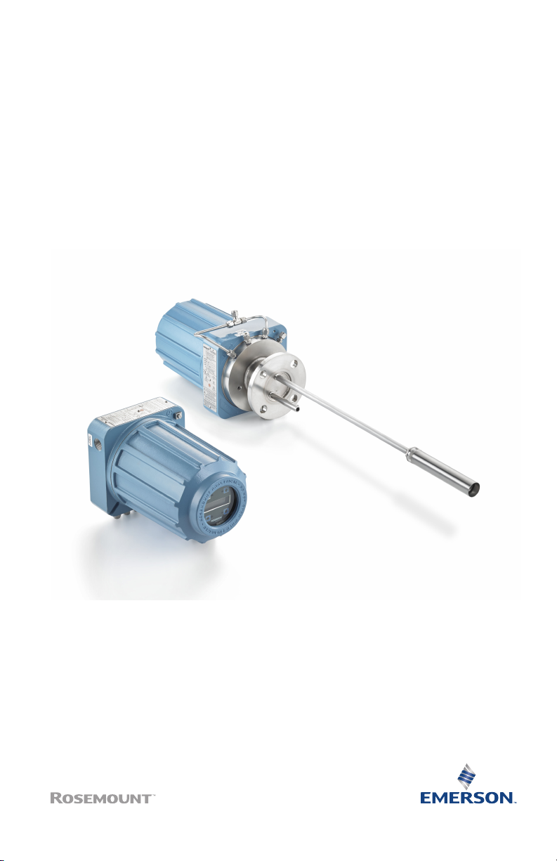
Rosemount™ OCX8800 Oxygen and
Combustibles Transmitter
with 4–20 mA HART® Protocol
Quick Start Guide February 2020
Essential instructions
Emerson designs, manufactures, and tests its products to meet many national and international
standards. Because these instruments are sophisticated technical products, you must properly install,
use, and maintain them to ensure they continue to operate within their normal specifications. You
must adhere to the following instructions and integrate them into your safety program when
installing, using, and maintaining Emerson's Rosemount products.
• Read all instructions prior to installing, operating, and servicing the product.
• Install equipment as specified in the installation instructions of the appropriate Reference Manual
and per applicable local and national codes. Connect all products to the proper electrical and
pressure sources.
Symbols
Earth (ground) terminal
Protective conductor terminal
Risk of electrical shock
Refer to reference manual.
Contents
Description and specifications......................................................................................................3
Installation................................................................................................................................... 4
Configuration and startup.......................................................................................................... 27
Using the local operator interface (LOI)...................................................................................... 35
Calibration................................................................................................................................. 38
Product certifications................................................................................................................. 46
Declaration of Conformity..........................................................................................................51
China RoHS table........................................................................................................................54
2 Emerson.com/Rosemount

February 2020 Quick Start Guide
1 Description and specifications
1.1 Component checklist
Check the model number of your Rosemount OCX8800 against the
transmitter features and options, making sure options specified by this
number are on or included with the unit. Use this complete model number
for any correspondence with Emerson.
Optional accessories provides a list of accessories for use with the
Rosemount OCX8800.
Quick Start Guide 3

Quick Start Guide February 2020
2 Installation
2.1 Product safety
WARNING
EXPLOSIONS
The Rosemount OCX8800 may explode if used in hazardous areas.
The Rosemount OCX88A can be installed in general purpose areas only.
Do not install the Rosemount OCX88A in hazardous areas.
To maintain explosion-proof protection of the Rosemount OCX88C in
hazardous areas, all cable entry devices and blanking elements for
unused apertures must be certified flameproof, suitable for the
conditions of use, and properly installed.
To maintain explosion-proof protection of the Rosemount OCX88C in
hazardous areas, the sensor housing must not be mounted to any
surface or flange that exceeds 383 °F (195 °C).
To maintain explosion-proof protection of the Rosemount OCX88C in
hazardous areas, the sample entering the sensor housing must not
exceed 383 °F (195 °C).
WARNING
PHYSICAL ACCESS
Unauthorized personnel may potentially cause significant damage to and/or
misconfiguration of end users’ equipment. This could be intentional or
unintentional and needs to be protected against.
2.2 Mechanical installation
2.2.1 Select a location
The location of the transmitter in the stack or flue is important for maximum
accuracy in the oxygen analyzing process. You must position the probe so
the gas it measures is representative of the process.
For best results, position the transmitter near the center of the duct (40 to
60 percent insertion). Longer ducts may require several transmitters since
the oxygen and combustibles can vary due to stratification. A point too near
the wall of the duct or the inside radius of a bend may not provide a
representative sample because of the very low flow conditions. Select the
sensing point so the process gas temperature falls within the range of probe
material used. #unique_11/unique_11_Connect_42_fig_rds_cc3_5jb
4 Emerson.com/Rosemount

February 2020 Quick Start Guide
through #unique_11/unique_11_Connect_42_fig_a2b_pl3_5jb provide
mechanical installation references.
CAUTION
Damage to the electronics may result.
Do not allow the temperature of the electronics housing to exceed 185 °F
(85 °C).
CAUTION
Failure to connect the pneumatic lines can allow the flow of contaminants
into the transmitter's ports.
Whenever a positive stack pressure exists at the installation site, be sure to
connect all pneumatic lines prior to installing the transmitter in the stack or
ductwork.
Procedure
1. Check the flue or stack for holes and air leakage.
The presence of this condition will substantially affect the accuracy of
the oxygen and combustibles readings. Make the necessary repairs
or install the transmitter upstream of any leakage.
2. Ensure the area is clear of internal and external obstructions that will
interfere with installation and maintenance access to the transmitter.
Allow adequate clearance for the removal of the transmitter.
2.2.2 Install
Procedure
1. Ensure all components are available to install the transmitter.
You may install the transmitter intact as it is received.
2. Weld or bolt adapter plate onto the duct.
3. Use the pipe or wall mounting hardware as shown in #unique_11/
unique_11_Connect_42_fig_tlq_kf3_5jb to mount a remote
electronics housing.
Choose a location that does not exceed the length of the electronics
cable ordered.
4. Ensure the conduits drop vertically from the transmitter and the
conduit is routed below the level of the conduit ports on the housing
to form a drip loop.
Quick Start Guide 5
Quick Start Guide February 2020
Drip loops minimize the possibility that moisture will damage the
electronics.
5. Where a positive stack pressure exists at the installation site, connect
all pneumatic lines prior to installing the transmitter in the stack or
ductwork.
CAUTION
If process temperatures will exceed 392 °F (200 °C), use anti-seize
compound on stud threads to ease future removal of the transmitter.
6. Insert sample and exhaust tubes through the opening in the
mounting flange and bolt the unit to the flange.
CAUTION
Uninsulated stacks or ducts may cause ambient temperatures in the
electronics housing to exceed 185 °F (85 °C) and damage the
electronics.
If insulation is removed to access the duct for mounting the
transmitter, make sure to replace insulation afterward.
2.3 Electrical installation
All wiring must conform to local and national codes. #unique_13/
unique_13_Connect_42_fig_hxd_nn5_5fb shows factory wired solenoid
power connections.
WARNING
Failure to install covers and ground leads could result in serious injury or
death.
Install all protective equipment covers and safety ground leads after
installation.
6 Emerson.com/Rosemount

February 2020 Quick Start Guide
WARNING
To meet the Safety Requirements of IEC 61010 (EC requirement), and
ensure safe operation of this equipment, connection to the main electrical
power supply must be made through a circuit breaker (min 10 A) in close
proximity and marked for this equipment which will disconnect all currentcarrying conductors during a fault situation. This circuit breaker should also
include a mechanically operated isolating switch. If not, then another
external means of disconnecting the supply from the equipment should be
located close by. Circuit breakers or switches must comply with a recognized
standard such as IEC 947.
Note
To maintain proper earth grounding, ensure a positive connection exists
between the sensor housing, the electronics housing, and earth. The
connecting ground wire must be 14 AWG minimum. Refer to #unique_13/
unique_13_Connect_42_fig_hxd_nn5_5fb.
Note
Line voltage, signal, and relay wiring must be rated for at least 221 °F
(105 °C).
2.3.1 Electrical connections
Make electrical connections, power, and communications to the electronics
enclosure through two ¾ national pipe thread (NPT) ports in the enclosure,
using fittings and cables provided by the customer.
Cable installation must meet NEC, IEC, and/or other applicable national or
local codes for Class I, Zone 1, IIB +H2 T3/T6 permanently mounted
equipment.
2.3.2 Connect line voltage
The transmitter operates on 100 to 240 Vac line voltage at 50 to 60 Hz. The
power supply requires no setup.
Connect the line (L wire) to the L terminal and the neutral (N wire) to the N
terminal on the AC power input terminal block in the electronics housing.
Connect the ground (G wire) to the ground stud in the electronics housing as
shown in #unique_13/unique_13_Connect_42_fig_hxd_nn5_5fb.
2.3.3 Connect output signals
The transmitter comes with two 4-20 mA signals with HART® on the oxygen
O2 signal.
Connect the output terminals in the electronics housing as shown in
#unique_13/unique_13_Connect_42_fig_hxd_nn5_5fb.
Quick Start Guide 7

Quick Start Guide February 2020
Use individual shielded twisted wire pairs. Terminate the shield at the
electronics housing.
2.3.4 Oxygen (O2) 4-20 mA signal
One 4-20 mA signal represents the O2 value.
The O2 signal is at the AOUT 1 terminals.
2.3.5 Combustibles equivalent (COe) 4-20 mA signal
Another 4-20 mA signal at the AOUT 2 terminals represents the COe value.
2.3.6 Alarm output relay
Connect any customer-supplied relay input to the alarm output relay
terminal. Use shielded wire and terminate the shield at the electronics
housing. The alarm output relay terminal is a set of dry, number 2, form C
contacts with 30 mA, 30 Vdc capacity.
2.3.7 Remote electronics connections to sensor housing
Make the following connections between the remote electronics and sensor
housings with the electronics cable ordered with the package (Figure 1).
Braided cable is available in lengths up to 150 ft. (46 m).
Note
Interconnect wiring shown is for Rosemount supplied cables. For customer
furnished interconnect wiring or cables, refer to Figure 1.
2.3.8 Signal connections
Connect the electronics housing terminals to the corresponding terminals in
the sensor housing. The twisted wire pairs are numbered on the inner plastic
wrapper.
Keep twisted pairs together and match the numbers and wire colors shown
in Figure 1.
2.3.9 Heater power connections
Use the blue, white, orange, black, red, and yellow stranded wires in the
heater power cable to connect power to the three heaters in the sensor
housing.
Match the wire colors to the corresponding heater power terminal blocks in
the sensor and electronics housings as shown in Figure 1.
2.4
8 Emerson.com/Rosemount
Pneumatic installation
Pneumatic system connections depend on whether reference air set,
calibration solenoids, and/or blowback equipment options are equipped on

February 2020 Quick Start Guide
your transmitter. Refer to the following sections and select the option that
applies to your transmitter configuration.
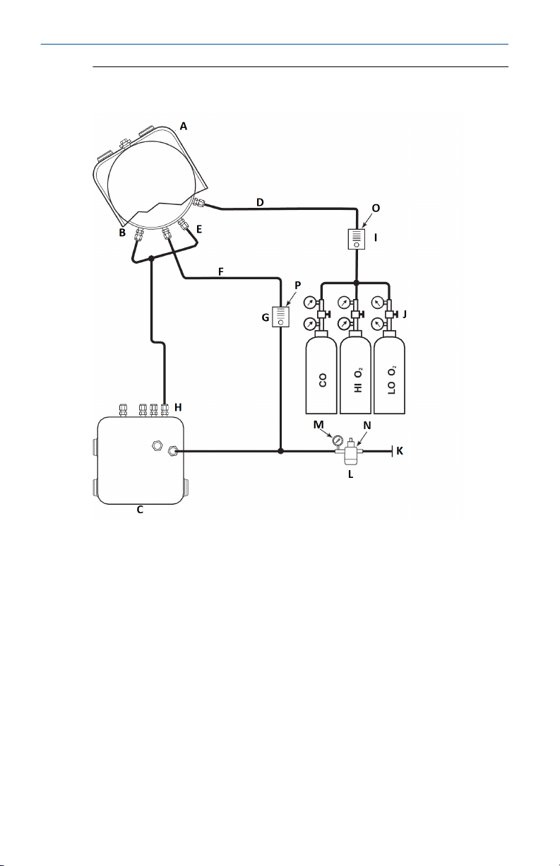
2.4.1 Reference air set option (only)
When no options or only the reference air set option is equipped, use the
following procedure to install the pneumatic system components.
Procedure
1. Refer to Figure 2-1. Connect the reference air set (regulator/filter and
pressure gage) to the instrument air inlet on the electronics housing
and to the inlet side of the dilution air flow meter.
2. Connect the dilution air flow meter output to the dilution air inlet
fitting on the sensor housing.
3. Install an air line between the instrument air outlet fitting on the
electronics housing and the tee fitting on the sensor housing.
CAUTION
Failure to use proper gases will result in erroneous readings.
Do not use 100 percent nitrogen as an O2 low gas.
Emerson suggests using O2 low gas between 0.4 percent and 2.0
percent O2.
Do not use gases with hydrocarbon concentrations of more than
40 parts per million.
4. Use one CO gas and two O2 gases to calibrate the transmitter.
• CO: 1000 ppm or up to 4 percent, balance air
• O2 low gas: 0.4 percent , balance N
• O2 high gas: 8 percent, balance N
2
2
5. Connect the output of the test gas sources to the inlet port of the
CAL GAS flow meter. Install an air line between the flow meter outlet
port and the CAL GAS inlet fitting on the sensor housing.
Quick Start Guide 9
Quick Start Guide February 2020
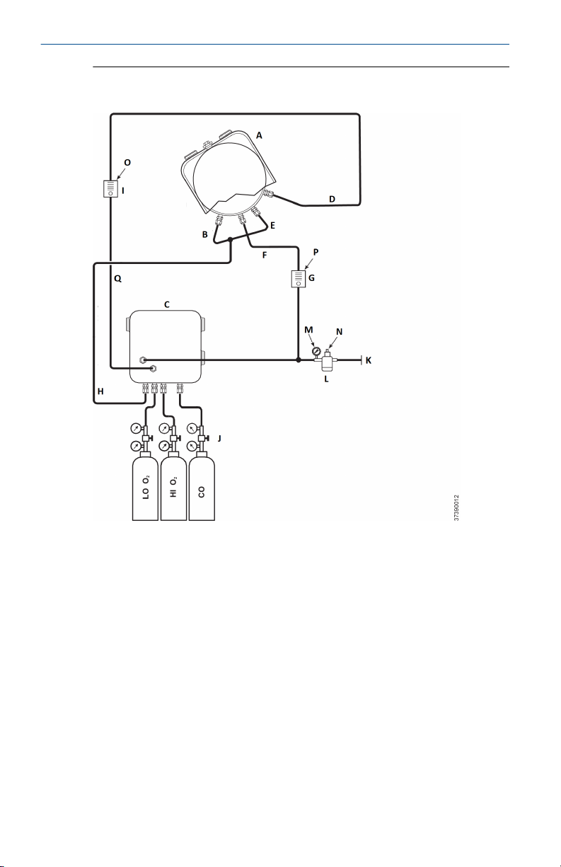
Figure 2-1: Pneumatic Installation, Rosemount OCX8800 with Reference
Air Set without Autocalibration
A. Sensor housing
B. Eductor air in
C. Electronics housing
D. Calibration gas in
E. Reference air in
F. Dilution air in
G. Dilution air flow meter 0.1 scfh
H. Instrument air out
I. Calibration gas flow meter (7 scfh, 20 to 30 psig [137.9 kPa to 206.8 kPa]
recommended)
J. Two-stage regulators
K. Instrument air supply
L. Pressure regulator/filter
General purpose: 35 psig (241.3 kPa)
Hazardous area: 45 psig (310.3 kPa)
10 Emerson.com/Rosemount

February 2020 Quick Start Guide
M. 2-in. (50.8 mm) pressure gauge, 0 to 60 psig (0 to 413.7 kPa)
N. Combination filter-regulator, 0 to 60 psig (0 to 413.7 kPa)
O. Flow meter, 1-10 scfh
P. Flow meter, 0.05-0.5 scfh
2.4.2 Reference air set and solenoids option without COe zero function
When the reference air set and test gas solenoids are included with your
transmitter, use the following procedure to install the pneumatic system
components.
Procedure
1. Install the reference air set according to the instructions in Reference
air set option (only), steps Step 1 through Step 3.
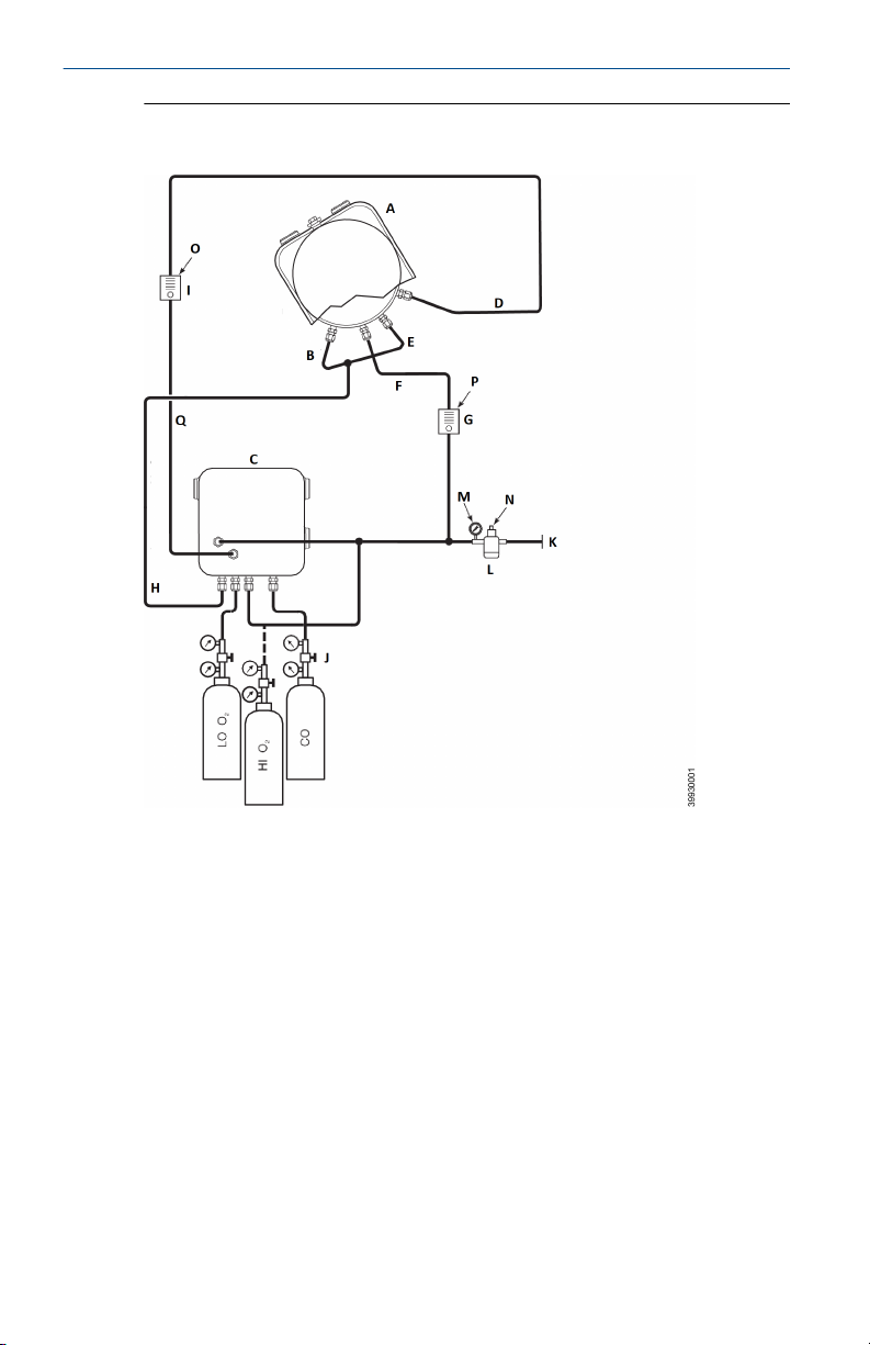
2. Refer to Figure 2-2. Connect the O2 low gas source to the CAL GAS
LO O2 inlet fitting on the electronics housing. Install a shutoff valve
and pressure regulator with gage in the O2 low supply line, as shown.
3. Connect the O2 high gas source to the CAL GAS HI O2 inlet fitting.
Install a shutoff valve and pressure regulator with gage in the O2 high
supply line.
4. Connect the CO high gas to the CAL GAS HI COe inlet fitting. Install a
shutoff valve and pressure regulator with gage in the CO high supply
line.
5. Connect the CAL GAS outlet fitting of the electronics housing to the
inlet port of the CAL GAS flow meter. Install an air line between the
flow meter outlet port and the CAL GAS inlet fitting on the sensor
housing.
Quick Start Guide 11
Quick Start Guide February 2020
Figure 2-2: Pneumatic Installation, Rosemount OCX8800 with Reference
Air Set, Solenoids, and Autocalibration, without COe Zero Function
A. Sensor housing
B. Eductor air in
C. Electronics housing
D. Calibration gas in
E. Reference air in
F. Dilution air in
G. Dilution air flow meter 0.1 scfh
H. Instrument air out
I. Calibration gas flow meter (7 scfh, 20-30 psig recommended)
J. Two-stage regulators
K. Instrument air supply
L. Pressure regulator/filter 35 psig - general purpose, 45 psig - hazardous
area
M. Two-in. pressure gauge 0-60 psig
N. Combination filter-reg. 0-60 psig
12 Emerson.com/Rosemount

February 2020 Quick Start Guide
O. Flow meter 1-10 scfh
P. Flow meter 0.05-0.5 scfh
Q. Calibration gas out
2.4.3 Reference air set and solenoids option with COe zero function
Figure 2-3 shows the piping arrangement for the transmitter with
autocalibration when the COe Zero Function is used. The arrangement is
similar to Figure 2-2 except instrument air is used as the Hi O2 test gas. Refer
to Configuration and start-up for details of this function.
Quick Start Guide 13
Quick Start Guide February 2020
Figure 2-3: Pneumatic Installation, Rosemount OCX8800 with Reference
Air Set, Solenoids, and Autocalibration, with COe Zero Function
A. Sensor housing
B. Eductor air in
C. Electronics housing
D. Calibration gas in
E. Reference air in
F. Dilution air in
G. Dilution air flow meter 0.1 scfh
H. Instrument air out
I. Calibration gas flow meter (7 scfh, 20-30 psig recommended)
J. Two-stage regulators
K. Instrument air supply
L. Pressure regulator/filter 35 psig - general purpose, 45 psig - hazardous
area
M. 2-in. (50.8 mm) pressure gauge, 0-60 psig
N. Combination filter-regulator, 0-60 psig
14 Emerson.com/Rosemount

February 2020 Quick Start Guide
O. Flow meter, 1-10 scfh
P. Flow meter, 0.05-0.5 scfh
Q. Calibration gas out
Note
If instrument is to be used as the high O2 calibration gas, the low O2 and COe
calibration gases must also be set to the same pressure (e.g., 35 psig).
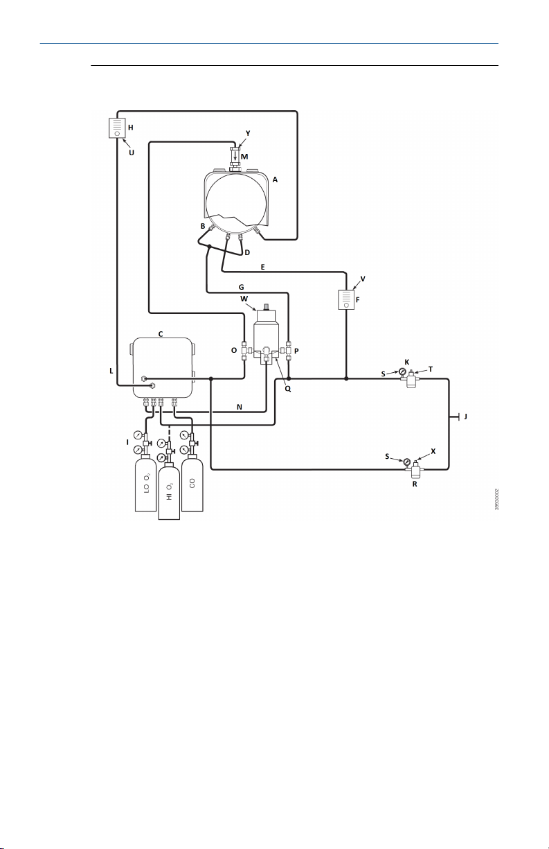
2.4.4 Reference air set, solenoids, and blowback option with COe zero function
Figure 2-4 shows the piping arrangement for the transmitter with the
blowback and autocalibration options when COe zero function is used. The
arrangement is similar to Figure 2-2 except instrument air is used as the Hi
O2 test gas. Refer to Configuration and start-up for details of this function.
Quick Start Guide 15
Quick Start Guide February 2020
Figure 2-4: Pneumatic Installation, Rosemount OCX with Reference Air
Set, Solenoids, Blowback and Autocalibration, with COe Zero Function
A. Sensor housing
B. Eductor air in
C. Electronics housing
D. Reference air in
E. Dilution air in
F. Dilution air flow meter, 0.1 scfh
G. Instrument air
H. Calibration gas flow meter (7 scfh, 20-30 psig recommended)
I. Two-stage regulators
J. Instrument air supply
K. Pressure regulator/filter, 35 psig - general purpose
L. Calibration gas out
M. Check valve
N. Actuating air
16 Emerson.com/Rosemount

February 2020 Quick Start Guide
O. Normally open solenoid valve
P. Normally closed solenoid valve
(1)
(1)
Q. Blowback valve, air operated
R. 2-in. (50.8 mm) pressure gauge, 0-60 psig
S. Combination filter/regulator, 0-60 psig
T. Flow metet, 1-10 scfh
U. Flow meter, 0.05-0.5 scfh
V. Pneumatic actuator
W. Combination filter/regulator, 0.60 psig
X. Check valve, 5 psig
Note
Wall mount the air-operated blowback valve on a suitable mounting plate.
Note
Actuating air pressure at blowback valve inlet port must be at least 51 psig
to fully actuate the valve.
Note
If instrument is to be used as the high O2 calibration gas, the low O2 and COe
calibration gases must also be set to the same pressure (e.g., 35 psig).
2.4.5 Reference air set, solenoids, and blowback option without COe zero function
Installing a transmitter with the blowback option requires the addition of air
operated blowback valve, regulator and gage, and check valve. Figure 2-5
shows the piping arrangement for the transmitter with the blowback and
autocalibration options. Figure 2-4 shows the piping arrangement for the
transmitter with the blowback option, but without autocalibration (without
test gas solenoids). When the reference air set, calibration gas solenoids,
and blowback options are included with your transmitter, use the following
procedure to install the pneumatic system components.
Procedure
1. Connect the calibration gas sources according to the instructions
Reference air set and solenoids option without COe zero function,
steps Step 2 through Step 5.
2. Connect a clean, dry, instrument-quality supply of air (20.95 percent
O2) to the 45 psig and 55 psig pressure regulators.
The inlet to the 45 psig regulator accepts a ⅛-in. NPT fitting. The
inlet to the 55 psig regulator accepts a ¼-in. NPT fitting.
(1) During blowback operation, states of both solenoid valves change.
Quick Start Guide 17

Quick Start Guide February 2020
3. See the upper leg of the instrument air supply. Connect the output of
the 35 psi regulator/filter to one port of the normally closed airoperated solenoid valve, and to the inlet side of the dilution air flow
meter.
4. Connect the dilution air flow meter output to the DILUTION AIR inlet
fitting on the sensor housing.
5. Install an instrument air line between the open port of the normally
open air-operated solenoid valve and the tee fitting on the sensor
housing.
6. Connect the output of the 55 psi regulator/filter to one port of the
normally open air-operated solenoid valve, and to the instrument air
inlet on the back of the electronics housing.
7. Install an air line between the open port of the normally closed airoperated solenoid valve and the check valve inlet fitting on the
sensor housing.
8. Install an air line between the instrument air outlet fitting on the
electronics housing and the control air inlet fitting on the airoperated solenoid valve.
18 Emerson.com/Rosemount

February 2020 Quick Start Guide
Figure 2-5: Pneumatic Installation, Rosemount OCX8800 with Reference
Air Set, Solenoids, Blowback, and Autocalibration without COe Zero
Function
A. Sensor housing
B. Eductor air in
C. Electronics housing
D. Reference air in
E. Dilution air in
F. Dilution air flow meter 0.1 scfh
G. Instrument air
H. Calibration gas flow meter (7 scfh, 20-30 psig recommended)
I. Two-stage regulators
J. Instrument air supply
K. Pressure regulator/filter 35 psig - general purpose
L. Calibration gas out
M. Check valve
N. Actuating air
Quick Start Guide 19

Quick Start Guide February 2020
O. Normally open solenoid valve
P. Normally closed solenoid valve
(2)
(2)
Q. Blowback valve, air operated
R. Two-in. pressure gauge 0-60 psig
S. Combination filter-reg. 0-60 psig
T. Flow meter 1-10 scfh
U. Flow meter 0.05-0.5 scfh
V. Pneumatic actuator
W. Combination filter/reg. 0.60 psig
X. Check valve 5 psig
Note
Wall mount the air-operated blowback valve on a suitable mounting plate.
Note
Actuating air pressure at blowback valve inlet port must be at least 51 psig
to fully actuate the valve.
CAUTION
If regulators are not installed in correct locations, the transmitter will not
work.
Pressure regulator with ⅛-in. inlet port is factory set for 35 psig. Regulator
with ¼-in. inlet port is factory set for 55 psig.
2.4.6 Reference air set and blowback panels
An optional blowback panel is shown in Figure 2-1. Piping arrangement for
blowback panel without autocalibration without COe zero function is shown
in Figure 2-5. Piping arrangement for blowback panel with autocalibration
without COe zero function is shown in Figure 2-6. Piping arrangement for
blowback panel with autocalibration with COe zero function is shown in
Figure 2-11.
(2) During blowback operation, states of both solenoid valves change.
20 Emerson.com/Rosemount

February 2020 Quick Start Guide
Figure 2-6: Pneumatic Installation, Blowback Panel without
Autocalibration without COe Zero Function
A. Sensor housing
B. Eductor air in
C. Electronics housing
D. Calibration gas in
E. Reference air in
F. Dilution air in
G. Instrument air
H. Instrument air out
I. Calibration gas out
J. Dilution air out
K. Blowback air out
L. Blowback control air
Quick Start Guide 21

Quick Start Guide February 2020
M. Instrument air supply
N. Instrument air to electronics
O. Two-stage regulators
P. Actuating air
Q. Check valve
22 Emerson.com/Rosemount

February 2020 Quick Start Guide
Figure 2-7: Pneumatic Installation, Blowback Panel with Autocalibration
without COe Zero Function
A. Sensor housing
B. Eductor air in
C. Electronics housing
D. Calibration gas in
E. Reference air in
F. Dilution air in
G. Instrument air
H. Instrument air out
I. Calibration gas out
J. Dilution air out
Quick Start Guide 23

Quick Start Guide February 2020
K. Blowback air out
L. Blowback control air
M. Instrument air supply
N. Instrument air to electronics
O. Two-stage regulators
P. Actuating air
Q. Check valve
24 Emerson.com/Rosemount

February 2020 Quick Start Guide
Figure 2-8: Pneumatic Installation, Blowback Panel with Autocalibration
with COe Zero Function
A. Sensor housing
B. Eductor air in
C. Electronics housing
D. Calibration gas in
E. Reference air in
F. Dilution air in
G. Instrument air
H. Instrument air out
I. Calibration gas out
J. Dilution air out
Quick Start Guide 25

Quick Start Guide February 2020
K. Blowback air out
L. Blowback control air
M. Instrument air supply
N. Instrument air to electronics
O. Two-stage regulators
P. Actuating air
Q. Check valve
26 Emerson.com/Rosemount

February 2020 Quick Start Guide
3 Configuration and startup
WARNING
Failure to install covers and ground leads could result in serious injury or
death.
Install all protective equipment covers and safety ground leads after
installation.
3.1 Verify installation
Ensure the transmitter is installed correctly. Verify mechanical installation
and all electrical and pneumatic connections.
CAUTION
Damage can result from having a cold transmitter exposed to the process
gases.
Make sure that the transmitter is turned on and operating prior to firing
up the combustion process.
During outages, and whenever possible, leave all transmitters running to
prevent condensation and premature aging from thermal cycling.
3.1.1 Verify configuration - HART® electronics
There are three switches on the microprocessor board which are user
configurable for the Rosemount OCX8800 with HART electronics (Figure
3-1).
SW1 determines if the O2 4-20 mA signal is internally or externally powered.
SW2 determines if the COe 4-20 mA signal is internally or externally
powered. SW3 sets the rail limits for the O2 and COe 4-20 mA signals and
configures the sample line heater control circuit. All switches are accessible
through holes in the electronics box.
CAUTION
If defaults are changed under power, damage to the electronics may occur.
Remove power from the transmitter before changing defaults.
Verify that the following switch settings are correct for your installation:
Quick Start Guide 27

Quick Start Guide February 2020
Figure 3-1: Rosemount OCX8800 Defaults - HART Electronics
A. Switch default positions shown
B. O2 21.1 mA / 3.5 mA: O2 4-20 mA signal
Rail limits:
Open High: 21.1 mA
Closed Low: 3.5 mA
COe 21.1 mA/3.5 mA: COe 4-20 mA signal
Rail limits:
Open High: 21.1 mA
Closed Low: 3.5 mA
C. Internal: COe 4-20 mA is internally powered.
D. External: COe 4-20 mA requires an external power supply (default).
E. Internal: O2 4-20 mA is internally powered.
F. External: O2 4-20 mA requires an external power supply (default).
SW1: The two settings are internally or externally powering the O2 4-20 mA
signal. The factory setting is for the O2 4-20 mA signal to be internally
powered.
28 Emerson.com/Rosemount

February 2020 Quick Start Guide
SW2: The two settings are internally or externally powering the COe 4-20
mA signal. The factory setting is for the COe 4-20 mA signal to be internally
powered.
SW3: The factory sets this switch as follows:
• Position 1 determines the O2 4-20 mA signal rail limit. The settings are
high, 21.1 mA, or low, 3.5 mA. The factory setting is low, 3.5 mA.
• Position 2 determines the COe 4-20 mA signal rail limit. The settings are
high, 21.1 mA, or low, 3.5 mA. The factory setting is high, 21.1 mA.
Positions 3 and 4 must be set as shown for proper software control of the
device heaters.
3.2 Initial power up
Allow adequate time (approximately 60 minutes) for the heaters to begin
operation and for the transmitter to reach normal operating temperature on
power up.
Normal operating temperature for the O2 cell is 1357 °F (736 °C). Normal
operating temperature for the combustibles cell is 572 °F (300 °C). The
normal sample line temperature is 338 °F (170 °C). During this time, the
eductor air solenoid will remain closed, so no sample is pulled through the
transmitter. When the transmitter reaches operating temperature, the
solenoid will energize, eductor air will begin to flow, and the transmitter will
begin normal operation.
3.3 Setting test gas values
3.3.1
Procedure
1. From O2 CAL PARAMS, select O2 HIGH GAS. Enter the percent O
used for the high O2 test gas.
2. From O2 CAL PARAMS, select O2 LOW GAS. Enter the percent O2 used
for the low O2 test gas.
3. From the DETAILED SETUP menu, select COe CALIB PARAMS.
4. From COe CAL PARAMS, select COe Test Gas. Enter the CO
concentration (ppm) used for COe test gas.
3.3.2 Set test gas values with the local operator interface (LOI)
Procedure
1. Use the "Z" pattern to enter the LOI menu tree.
2. From the SYSTEM menu, select Calib Setup.
Quick Start Guide 29
2

Quick Start Guide February 2020
3. From Calib Setup, select O2 High Gas %. Enter the percent O2 used
for the high O2 test gas.
4. Press Down, and the next selection will be O2 Low Gas %. Enter the
percent O2 used for the low O2 test gas.
5. Press Down several times to display COe Test Gas. Enter the CO
concentration (ppm) used for COe test gas.
3.4 Calibration solenoids
Emerson can provide the transmitter with optional calibration solenoids for
autocalibration. The transmitter's software controls the solenoids, which
automatically switch in the proper calibration gas during the calibration
cycle.
3.4.1 Configure the calibration solenoids with the Field Communicator -
®
HART
Procedure
1. Use the Field Communicator to access the HART menu.
2. From the DETAILED SETUP menu, select CAL SETUP.
3. From the CAL SETUP menu, select O2 CAL PARAMS/COe CAL PARAMS.
4. From the O2 CAL PARAMS/COe CAL PARAMS, select Solenoids. Select
Yes to enable the solenoids.
3.4.2 Configure the calibration solenoids with the LOI
Procedure
1. Use the Z pattern to enter the LOI menu tree.
2. From the SYSTEM menu, select Calib Setup.
3. From the Calib Setup menu, select Use Solenoids. Select Yes to enable
the solenoids.
3.5
Blowback feature
The blowback feature blows instrument air back through the center of the
internal filter and out the sample tube of the probe. This removes built up
dirt and particulate from the internal filter, sample line, and any optional insitu filter on the end of the sample tube.
The blowback feature is normally used in systems that have heavy
particulate in the process stream. The blowback feature requires the
optional blowback hardware to be properly installed external to the
transmitter. A Rosemount OCX8800 shipped from the factory must be
configured before blowback can be implemented. This same process must
be performed any time a replacement card stack is installed.
30 Emerson.com/Rosemount

February 2020 Quick Start Guide
3.5.1 Configure blowback with the Field Communicator - HART
Procedure
1. Use the Field Communicator or AMS software to access the HART
menu.
2. From the DETAILED SETUP menu, select INPUT/OUTPUT.
3. From the INPUT/OUTPUT menu, select BLOWBACK.
4. From the BLOWBACK menu, select BlBk Enabled. Select Yes to enable
blowback. Also set the following parameters:
• BlBk Intrvl: Length of time between blowback events (60 minutes
recommended).
• BlBk Period: Length of time blowback is activated (five seconds
recommended).
• BlBk Purge Time: Length of time after blowback is complete
before oxygen / combustibles readings are considered valid (set
as required by the application).
5. Manually initiate blowback from DIAG/SERVICE.
3.5.2 Configure blowback with the LOI
Procedure
1. Use the Z pattern to enter the LOI menu tree.
2. From the SYSTEM menu, select Blow Back.
3. From the Blow Back menu, select Blow Bk Enable. Select Yes to enable
blowback. Also set the following parameters:
• Blow Bk Intrvl: Length of time between blowback events. Range is
0 to 32,000 minutes. Default is 60 minutes. Emerson
recommeneds 60 minutes.
• Blow Bk Period: Length of time blowback in activated. Range is
one to five seconds. Default is two seconds. Emerson
recommends five seconds.
• Blow Bk Purge: Length of time after blowback is complete before
oxygen/combustibles readings are considered valid. Range is 0 to
500 seconds. Default is 88 seconds. Set as required by the
application.
• Force Blow Bk: Initiates a blow back event manually.
®
Quick Start Guide 31

Quick Start Guide February 2020
3.6 COe purge/zero feature
This feature provides a way to periodically flood the COe sensor with air to
perform two functions:
1. Provide additional oxygen to help burn off any combustible residue
from the COe sensor.
2. Allow for optional adjustment of the COe calibration constant.
If the transmitter is configured to update the COe calibration constant, only
the constant is updated. The COe calibration slope is not affected. To update
both the constant and slope, you must do a full calibration.
The feature uses the calibration solenoid that is also used for high O2 test gas
and COe zero gas. For the feature to work properly, instrument air is used as
the high O2 test gas. This also requires the high O2 test gas value to be set at
20.95 percent. You can install a two-way valve to switch the high O2 test gas
between the normal calibration gas and instrument air. This allows the
transmitter to use a specified calibration gas for calibration, then instrument
air for the COe zero feature. Switching between the two gases must be
manually coordinated between scheduled calibrations and COe zero events.
When the COe zero feature is used, special pneumatic connections are
required.
The COe zero feature is only valid if the transmitter is supplied with
calibration solenoids and the solenoids have been activated.
A Rosemount OCX8800 shipped from the factory must be configured before
the COe zero feature can be implemented. This same process must be
performed any time a replacement card stack is installed.
WARNING
During the COe Zero Function, the analog output signals may track the
oxygen and combustibles readings if configured to do so.
To avoid a potentially dangerous operating condition, remove the
transmitter from the automatic combustion control loop before performing
the COe Zero Function procedure.
Note
At the completion of the COe Zero Function, the COe analog output signal
will change if the Zero Update parameter is set to Yes.
32 Emerson.com/Rosemount

February 2020 Quick Start Guide
3.6.1 Configure COe zero with the Field Communicator - HART
Procedure
1. Use the Field Communicator or AMS software to access the HART
menu.
2. From the DETAILED SETUP menu, select INPUT/OUTPUT.
3. From the INPUT/OUTPUT menu, select COE ZERO.
4. From the COE ZERO menu, select the functions as follows:
• Zero Enabled: Select Yes or No to enable or disable this feature.
• Zero Intrvl: Length of time between COe zero events. Range is 60
to 480 minutes. Default is 60 minutes.
• Zero Flow: Length of time COe zero gas flows. Range is 120 to
600 seconds. Default is 120 seconds.
• Zero Purge: Length of time after COe zero is complete before
oxygen/combustibles readings are considered valid. Range is 60
to 180 seconds. Default is 60 seconds. Total duration of this
function is flow time plus purge time.
• Zero Tracks: Determines if the analog output signals track or hold
during the function. Valid choices are None, Both, COe, and O2.
• Zero Update: Determines if the COe calibration constant is
updated at the end of the function. Valid choices are Yes and No.
A Yes choice will cause the COe calibration constant to update.
®
Note
At the completion of the COe Zero Function, the COe analog output
signal will change if the Zero Update parameter is set to Yes.
3.6.2 Configure COe zero with the LOI
Procedure
1. Use the Z pattern to enter the LOI menu tree.
2. From the SYSTEM menu, select Input/Output.
3. From the Input/Output menu, select COe Zero. Select the functions as
follows:
• COe Zero Enable: Select Yes or No to enable or disable this
feature.
• COe Zero Intrvl: Length of time between COe zero events. Range
is 60 to 480 minutes. Default is 60 minutes.
• COe Zero Flow: Length of time COe zero gas flows. Range is 120
to 600 seconds. Default is 120 seconds.
Quick Start Guide 33

Quick Start Guide February 2020
• COe Zero Purge: Length of time after COe zero is complete
before oxygen/combustibles readings are considered valid.
Range is 60 to 180 seconds. Default is 60 seconds. Total duration
of this function is flow time plus purge time.
• COe Zero Tracks: Determines if the analog output signals track or
hold during the function. Valid choices are None, Both, COe, and
O2.
• COe Zero Update: Determines if the COe calibration constant is
updated at the end of the function. Valid choices are Yes and No.
A Yes choice will cause the COe calibration constant to update.
34 Emerson.com/Rosemount

February 2020 Quick Start Guide
4 Using the local operator interface (LOI)
4.1 Local operator interface (LOI) controls
4.1.1 LOI assembly
Figure 4-1: LOI Assembly
A. Touch confirmation LED
B. Selection arrow
C. Lockout notation
D. Status code
E. Selection arrow
F. Display window
G. Selection arrow (enter key)
4.1.2 Local operator interface (LOI) key functions
The gray (top left) key will move one level higher in the menu structure.
When entering parameter values (numbers), this key moves the cursor to
the left. The left-pointing key also doubles as an Enter key, used after the
digits of a parameter value are entered and the cursor is moved to its leftmost position. When you touch the Enter key, the new parameter value, if
accepted, will appear in the top line of the display.
Quick Start Guide 35

Quick Start Guide February 2020
Use the blue (bottom left) key as a selector when choosing from among
several menu items. This right-pointing key also will move the cursor to the
right when entering the digits of a new parameter value.
Use the up and down pointing keys to increment up and down when
selecting from a vertical list of menu items. You can also use these keys for
incrementing values up and down for new data input.
4.1.3 Lockout
The local operator interface (LOI) has a lockout feature that prevents
nuisance actuation by someone brushing against the glass window,
raindrops, dirt, insects, etc. This lockout mode is automatically established
when no buttons are pushed for 30 seconds (default). This countdown to
lockout is configurable.
In order to unlock the display, input a Z pattern (Figure 4-2). First, touch the
top left (gray) Enter key. Next, touch the top right key, followed by the
bottom left key and the bottom right key. The LK notation in the upper right
corner of the display will disappear. Touch Enter once more to enter into the
menu structure. Whenever you touch a key, additional time to lockout is
provided, so that the lockout feature does not become a nuisance. This
additional revert time is one hour (default) and is also user configurable.
CAUTION
Excessive dust can prevent the LOI from entering lockout. This condition can
cause uncommanded operations to occur.
Always clean dust and soil away from the LOI screen each time the LOI is
used.
36 Emerson.com/Rosemount

February 2020 Quick Start Guide
Figure 4-2: Z Pattern Entry
Quick Start Guide 37

Quick Start Guide February 2020
5 Calibration
5.1 Fully automatic calibration
If the transmitter is equipped with calibration solenoids, you can program it
to automatically calibrate without any operator action.
Refer to Set up autocalibration using the local operator interface (LOI) or Set
up autocalibration using HART® to set up the transmitter for fully automatic
calibration.
5.1.1 Set up autocalibration using HART
Use the following procedure to specify a time interval (in hours) at which the
transmitter will automatically calibrate.
Note
Automatic calibration is only available on transmitters equipped with
calibration solenoids.
Procedure
1. From the DEVICE SETUP screen, select DETAILED SETUP.
2. From the DETAILED SETUP screen, select O2 CALIB PARAMS or COE
CALIB PARAMS.
3. If the transmitter is equipped with calibration solenoids and you want
timed automatic calibrations, select Solenoids; then select Yes.
Select No to disable the calibration solenoids.
4. Select O2 CalIntrvl (O2 calibration interval) and enter the desired
time in hours between automatic O2 calibrations. Select COE
Callintrvl and enter the desired time between automatic COe
calibrations. To disable automatic calibration for O2 and COe, enter 0
for both CalIntrvl parameters.
If you want, you can change the O2 NxtCalTm and the COeNxtCalTm
(next calibration time) parameters to synchronize a calibration at a
specific day or time.
®
CAUTION
When setting automatic calibration times, set CalIntrvl and NxtCalTm so
that O2 and COe are NOT calibrated simultaneously.
Note
To select a menu item, either press Up and Down to scroll to the menu item
and press Right or use the number keypad to select the menu item number.
38 Emerson.com/Rosemount

February 2020 Quick Start Guide
To return to a preceding menu, press Left.
5. From the O2 CALIB PARAMS screen, select CalIntrvl (O2 calibration
interval).
6. At the prompt, input a time interval (in hours) at which an automatic
O2 calibration will occur and press ENTER.
7. From the DETAILED SETUP screen, select COE CALIB PARAMS.
8. From the COE CALIB PARAMS menu, select CalIntrvl.
9. At the prompt, input a time interval (in hours) at which an automatic
COe calibration will occur and press ENTER.
5.2 Operator-initiated autocalibration
An operator can initiate an automatic calibration at any time, as long as the
transmitter is equipped with calibration solenoids.
5.2.1 Autocalibrate using HART
Procedure
1. From the DEVICE SETUP menu, select DIAG/SERVICE.
2. From the DIAG/SERVICE menu, select CALIBRATE.
3. From the CALIBRATE menu, select PERFORM CAL.
4. From the PERFORM CAL menu, select CAL METHODS.
5. From the CAL METHODS menu, select the type of calibration desired:
O2 Calibration, COe Calibration, or O2 and COe Calibration.
®
5.3
Manual calibration
If a transmitter is not equipped with calibration solenoids, an operator must
calibrate by following prompts from the transmitter.
5.3.1 Calibrate manually using the optional local operator interface (LOI)
If necessary, refer to Figure 1. Once the the operator initiates the manual
calibration procedure at the LOI, a series of prompts will appear giving
instructions to the operator.
Procedure
1. Press Right to select the CALIBRATION first column submenu.
2. From the CALIBRATION submenu, press Right to select the Cal Control
second column submenu.
3. From the Cal Control submenu, press Right to select the third column
Start Cal O2 option.
Quick Start Guide 39

Quick Start Guide February 2020
4. Remain at Start Cal O2 or press Down to select Start Cal COe or
Start Cal Both.
The following sequence applies when you select Start Cal Both.
5. Press Right to start the calibration. Turn on the low O2 test gas, when
prompted by the Flow Low Gas message.
6. Press Right after applying the low O2 test gas.
The calibration data changes as the calibration proceeds.
7. Press Right when the low O2 reading is stable. Turn off the low O
2
test gas and turn on the high O2 test gas as prompted by the Flow
High Gas message.
8. Press Right after applying the high O2 test gas.
The calibration data changes as the calibration proceeds.
9. Press Right when the high O2 reading is stable. Turn off the high O
2
test gas. Press Right to start the high O2 gas purge.
When the purge period expires, the LOI display reverts to the normal
operation display. If the calibration failed, the display will indicate an
alarm condition.
10. Press Right to start combustibles calibration. Turn on the CO test gas
when prompted.
11. Press Right after applying the CO test gas.
The calibration data changes as the calibration proceeds.
12. Press Right when the CO reading is stable.
13. Turn off the CO test gas and press Right to start the CO gas purge.
When the purge period expires, the LOI display reverts to the normal
operation display. If the calibration failed, the display will indicate an
alarm condition.
5.3.2 Calibrate O2 manually using the Field Communicator - HART
®
To perform a manual O2 calibration using the HART communicator or AMS,
use the following procedure.
Note
To select a menu item, either use the up and down arrow keys to scroll to the
menu item and press the right arrow key or use the number keypad to select
the menu item number.
To return to a preceding menu, press the left arrow key.
Procedure
1. Select DIAG/SERVICE from DEVICE SETUP menu.
2. Select CALIBRATION from the DIAG/SERVICE menu.
3. Select CAL CONTROL from the CALIBRATION menu.
40 Emerson.com/Rosemount

February 2020 Quick Start Guide
4. Select CAL METHODS from the CAL CONTROL menu.
5. From the CAL METHODS menu, select the type of calibration desired:
O2 Calibration.
In the first Calibration screen, a Loop should be removed
from automatic control warning appears.
6. Remove the transmitter from any automatic control loops to avoid a
potentially dangerous operating condition and press OK.
7. The Calibration screen should be set to the following settings/values.
Press OK to continue.
• OCX: TAG NAME
• STATUS: Idle
• TIME REMAIN: 0s
• O2: 0.4 %, 85.95 mV
• OK/NEXT to Select
• ABORT/CANCEL to Exit
8. From the SELECT ACTION screen, select START/NEXT CALSTEP to
continue calibration, select ABORT CAL to abort calibration or EXIT
CAL to exit calibration. Select one item from the list and press ENTER.
• OCX: TAG NAME
• SELECT ACTION
— 1. START/NEXT CALSTEP
— 2. ABORT CAL
— 3. EXIT CAL
9. When the Calibration Status is at the AppO2Low step, switch on O
2
Low Gas. Verify the O2 concentration measured matches the O2 LOW
GAS parameter in the Setup. Press OK when ready.
10. Select Start/Next Cal Step to start applying the O2 Low Gas.
The time to apply the test gas is specified by the Gas Time.
The Calibration Status should be automatically changed to
FlowO2Low and then ReadO2Low for a period of time. During this
period, if you try to go to the next calibration step by pressing OK
and selecting Start/Next Cal Step, you will be prompted with
Operator step command is not accepted at this time. The Next Cal
Step command is not accepted at this time. When ready, Calibration
Status will stop at the AppO2Hi.
Quick Start Guide 41

Quick Start Guide February 2020
11. Switch off the O2 Low Gas and switch on the O2 High Gas. Verify the
O2 concentration measured matches the O2 HIGH GAS parameter in
the Setup. Press OK when ready.
12. Select Start/Next Cal Step to start applying the O2 High Gas.
The time to apply the test gas is specified by the Gas Time.
The Calibration Status should be automatically changed to
FlowO2Low and then ReadO2Low for a period of time. During this
period, if you try to go to the next calibration step by pressing OK
and selecting Start/Next Cal Step, you will be prompted with
Operator step command is not accepted at this time. The Next Cal
Step command is not accepted at this time. When ready, Calibration
Status will stop at the AppO2Hi. When ready, Calibration Status will
stop at STOP GAS.
13. Switch off the O2 High Gas. Press OK when ready. Select Start/Next
Cal Step to start purging gas.
The time to purge gas is specified by the Purge Time.
When the Purge step is complete, the Calibration Status will be at
IDLE if the calibration is successful or CAL RECOMMENDED if the
calibration has failed. A Calibration Failed alarm will be set if the
calibration has failed.
14. When calibration is complete, select Exit Cal to exit the calibration
method.
5.3.3 Calibrate COe manually using the Field Communicator: HART
®
If necessary, refer to Figure 1 for the HART menu tree.
Note
To select a menu item, either use Up and Down to scroll to the menu item
and press Right or use the number keypad to select the menu item number.
To return to a preceding menu, press Left.
Procedure
1. From the DIAG/SERVICE menu, select CALIBRATION.
2. From the CAL METHODS menu, select the type of calibration desired:
COe Calibration.
In the first Calibration screen, a Loop should be removed from
automatic control warning appears.
3. Remove the transmitter from any automatic control loops to avoid a
potentially dangerous operating condition and press OK.
4. Set the main Calibration screen to the following settings/values. Press
OK to continue.
• OCX: TAG NAME
42 Emerson.com/Rosemount

February 2020 Quick Start Guide
• STEP: Idle
• TIME REMAIN: 0s
• OK/NEXT to Select
• ABORT/CANCEL to Exit
5. Switch on the COe high gas. Verify the COe concentration measured
matches the COe HIGH GAS parameter in the Setup window. Press
OK when ready.
6. When calibration is complete, select Exit Cal to exit the calibration
method.
5.3.4 Calibrate O2 and COe manually using the Field Communicator:
HART
®
To perform a manual O2 and COe calibration using the Field Communicator
or AMS, use the following procedure.
Note
To select a menu item, use either Up or Down to scroll to the menu item and
press Right or use the number keypad to select the menu item number.
To return to a preceding menu, press the Left.
Procedure
1. Select DIAG/SERVICE from the DEVICE SETUP menu.
2. Select CALIBRATION from the DIAG/SERVICE menu.
3. Select CAL CONTROL from the CALIBRATION menu.
4. Select CAL METHODS from the CAL CONTROL menu.
5. From the CAL METHODS menu, select the type of calibration desired:
O2 and COe Calibration.
In the first Calibration screen, a Loop should be removed from
automatic control warning appears.
6. Remove the transmitter from any automatic control loops to avoid a
potentially dangerous operating condition and press OK.
7. Set the main Calibration screen to the following values. Press OK to
continue.
• OCX: TAG NAME
• STEP: Idle
• TIME REMAIN: 0s
• O2: 0.4%, 85.95mV
• COe: 0.20 ppm
Quick Start Guide 43

Quick Start Guide February 2020
• OK/NEXT to Select
• ABORT/CANCEL to Exit
8. From the SELECT ACTION screen, select START CAL/STEP CAL to
continue calibration, select ABORT CAL to abort calibration, or select
EXIT CAL to exit calibration method. Select one from the list and
press ENTER.
• OCX: TAG NAME
• SELECT ACTION
— 1. START CAL/STEP CAL
— 2. ABORT CAL
— 3. EXIT CAL
9. When the Calibration Status is at the AppO2Low step, switch on O
low gas. Verify the O2 concentration measured matches the O2 LOW
GAS parameter in Setup CAL. Press OK when ready.
10. When the Calibration Status is at the AppO2Low step, switch on O
low gas. Verify the O2 concentration measured matches the O2 LOW
GAS parameter in Setup. Press OK when ready.
11. Select START CAL/STEP to start applying the O2 low gas.
The time to apply the test gas is specified by the Gas Time.
The Calibration Status should automatically change to FIowO2Low
and then ReadO2Low for a period of time. During this period, if you
try to go to the next calibration step by pressing OK and selecting
START CAL/STEP CAL, you will be prompted with Operator step
command is not accepted at this time. When ready, Calibration
Status will stop at AppO2Hi.
12. Switch off the O2 low gas and switch on the O2 high gas. Verify the O
concentration measured matches the O2 HIGH GAS parameter in
Setup. Press OK when ready.
13. Select START CAL/STEP CAL to apply the O2 high gas.
The time to apply the test gas is specified by the Gas Time.
The Calibration Status should automatically change to FIowO2Hi
and then ReadO2HI for a period of time. During this period, if you try
to go to the next calibration step by pressing OK and selecting START
CAL/STEP CAL, you will be prompted with Operator step command
is not accepted at this time. When ready, Calibration Status will
stop at AppCOeHi.
2
2
2
44 Emerson.com/Rosemount

February 2020 Quick Start Guide
14. Switch off the O2high gas and switch on the COe Gas. Verify the COe
concentration measured matches the COe TEST GAS parameter in
the Setup. Press OK when ready.
15. Select START CAL/STEP CAL to start applying the COe Gas. The time
to apply the test gas is specified by the Gas Time.
The Calibration Status should automatically change to FIowCOeHi
and then ReadCOeHi for a period of time. During this period, if you
try to go to the next calibration step by pressing OK and selecting
START CAL/STEP CAL, you will be prompted with Operator step
command is not accepted at this time. The START CAL/STEP CAL
command is not accepted at this time. When ready, Calibration
Status will stop at STOP GAS.
16. Switch off the COe gas. Press OK when ready. Select START CAL/STEP
CAL to start purging gas.
The time to apply the test gas is specified by the Purge Time.
Quick Start Guide 45

Quick Start Guide February 2020
6 Product certifications
Rev 5.2
6.1 European Directive information
A copy of the EU Declaration of Conformity can be found at the end of the
Quick Start Guide. The most recent revision of the EU Declaration of
Conformity can be found at Emerson.com/Rosemount.
6.2 Ordinary location certification
As standard, the transmitter has been examined and tested to determine
that the design meets the basic electrical, mechanical, and fire protection
requirements by a nationally recognized test laboratory (NRTL) as accredited
by the Federal Occupational Safety and Health Administration (OSHA).
6.3 Installing equipment in North America
The US National Electrical Code® (NEC) and the Canadian Electrical Code
(CEC) permit the use of Division marked equipment in Zones and Zone
marked equipment in Divisions. The markings must be suitable for the area
classification, gas, and temperature class. This information is clearly defined
in the respective codes.
6.4 Rosemount OCX8800 Oxygen/Combustibles Transmitter (OCX88A) for general purpose locations
6.4.1 USA
CSA
Certificate:
Standards:
Markings:
Special Conditions for Safe Use (X):
1. Calibration air lines and reference air lines shall not contain pure
oxygen or combustible gas other than inert/oxygen gas mixture of
which oxygen represent no more than that normally present in air.
46 Emerson.com/Rosemount
1602514
C22.2 No. 0-10 (September 2010),
C22.2 No 94-M91 (R2006),
C22.2 No. 61010-1-12,
ANSI/ISA-61010-1 (82.02.01) (Third Edition)
UL 50 (Tenth Edition)
Type 4X, IP66**
**when reference air vents are routed to a dry area

February 2020 Quick Start Guide
2. The pressure within the enclosure and gas lines shall not be higher
than 1.1 times the atmospheric pressure during the normal
operation of the equipment.
3. Flameproof joints are not intended to repaired.
6.4.2 Canada
CSA
Certificate:
Standards:
Markings:
Special Conditions for Safe Use (X):
6.5
Rosemount OCX8800 Oxygen/Combustibles Transmitter (OCX88C) for Hazardous Locations
6.5.1 USA
1602514
C22.2 No. 0-10 (September 2010),
C22.2 No 94-M91 (R2006),
C22.2 No. 61010-1-12,
ANSI/ISA-61010-1 (82.02.01) (Third Edition)
UL 50 (Tenth Edition)
Type 4X, IP66**
**when reference air vents are routed to a dry area
1. Calibration air lines and reference air lines shall not contain pure
oxygen or combustible gas other than inert/oxygen gas mixture of
which oxygen represent no more than that normally present in air.
2. The pressure within the enclosure and gas lines shall not be higher
than 1.1 times the atmospheric pressure during the normal
operation of the equipment.
3. Flameproof joints are not intended to repaired.
CSA
Certificate:
Standards:
Quick Start Guide 47
1602514
C22.2 No. 0-10 (September 2010), C22.2 No 94-M91 (R2006)
C22.2 No. 61010-1-12, CAN/CSA-C22.2 No. 60079-0:15
CAN/CSA-C22.2 No. 60079-1:16, ANSI/ISA-60079-0
(12.00.01)-2013
ANSI/ISA-60079-1 (12.22.01)-2009 (R2013)
ANSI/ISA-61010-1 (82.02.01) (Third Edition)

Quick Start Guide February 2020
UL 50 (Tenth Edition)
Markings:
Class 1, Zone 1, AEx db IIB+H2 T* Gb
Ex db IIB+H2 T* Gb
Type 4X, IP66**
*Sensor assembly enclosure: T3 (-40 °C <= Tamb <= +100 °C)
*Electronics assembly enclosure: T6 (-40 °C <= Tamb <= +65
°C)
*Integral configuration: T3 (-40 °C <= Tamb <= +65 °C)
**when reference air vents are routed to a dry area
Special Conditions for Safe Use (X):
1. Calibration air lines and reference air lines shall not contain pure
oxygen or combustible gas other than inert/oxygen gas mixture of
which oxygen represent no more than that normally present in air.
2. The pressure within the enclosure and gas lines shall not be higher
than 1.1 times the atmospheric pressure during the normal
operation of the equipment.
3. Flameproof joints are not intended to repaired.
6.5.2 Canada
CSA
Certificate:
Standards:
Markings:
48 Emerson.com/Rosemount
1602514
C22.2 No. 0-10 (September 2010), C22.2 No 94-M91 (R2006)
C22.2 No. 61010-1-12, CAN/CSA-C22.2 No. 60079-0:15
CAN/CSA-C22.2 No. 60079-1:16, ANSI/ISA-60079-0
(12.00.01)-2013
ANSI/ISA-60079-1 (12.22.01)-2009 (R2013)
ANSI/ISA-61010-1 (82.02.01) (Third Edition)
UL 50 (Tenth Edition)
Class 1, Zone 1, AEx db IIB+H2 T* Gb
Ex db IIB+H2 T* Gb
Type 4X, IP66**
*Sensor assembly enclosure: T3 (-40 °C <= Tamb <= +100 °C)

February 2020 Quick Start Guide
*Electronics assembly enclosure: T6 (-40 °C <= Tamb <= +65
°C)
*Integral configuration: T3 (-40 °C <= Tamb <= +65 °C)
**when reference air vents are routed to a dry area
Special Conditions for Safe Use (X):
1. Calibration air lines and reference air lines shall not contain pure
oxygen or combustible gas other than inert/oxygen gas mixture of
which oxygen represent no more than that normally present in air.
2. The pressure within the enclosure and gas lines shall not be higher
than 1.1 times the atmospheric pressure during the normal
operation of the equipment.
3. Flameproof joints are not intended to repaired.
6.5.3 Europe
ATEX
Certificate:
Standards:
KEMA 04ATEX2308 X
EN IEC 60079-0:2018
EN 60079-1: 2014
Markings:
II 2G Ex db IIB + H2 T3 Gb*
*Temperature Classification and Ambient temperature
range:
T6 (split architecture – transmitter assembly) -40°C to +65°C
T3 (split architecture – sensor assembly) -40°C to +100°C
T3 (integral version) -40°C to +65°C
Special Conditions for Safe Use (X):
1. Calibration air lines and reference air lines shall not contain pure
oxygen or combustible gas other than inert/oxygen gas mixture of
which oxygen represents no more than normally present in air.
2. The pressure within the enclosure and gas lines shall not be higher
than 1.1 times atmospheric pressure during normal operation.
3. Flameproof joints are not intended to be repaired.
4. Precautions shall be taken to minimize the risk from electrostatic
discharge of painted parts.
Quick Start Guide 49

Quick Start Guide February 2020
6.5.4 International
IECEx
Certificate:
Standards:
IECEx CSA 10.0002X
IEC 60079-0: 2017 Edition 7.0
IEC 60079-1: 2014-06 Edition 7.0
Markings:
Transmitter: Ex db IIB+H2 T6 Gb; Tamb: -40 °C to 65 °C
Sensor: Ex db IIB+H2 T3 Gb; Tamb: -40 °C to 100 °C
Integral Version: Ex db IIB+H2 T3 Gb; Tamb: -40 °C to 65 °C
Special Conditions for Safe Use (X):
1. Calibration air lines and reference air lines shall not contain pure
oxygen or combustible gas other than inert/oxygen gas mixture of
which oxygen represents no more than normally present in air.
2. The pressure within the enclosure and gas lines shall not be higher
than 1.1 times atmospheric pressure during normal operation.
3. Flameproof joints are not intended to be repaired.
50 Emerson.com/Rosemount

February 2020 Quick Start Guide
7 Declaration of Conformity
Quick Start Guide 51

Quick Start Guide February 2020
52 Emerson.com/Rosemount

February 2020 Quick Start Guide
Quick Start Guide 53

Quick Start Guide February 2020
8 China RoHS table
54 Emerson.com/Rosemount

February 2020 Quick Start Guide
Quick Start Guide 55

*00825-0100-4880*
00825-0100-4880, Rev. AD
Quick Start Guide
February 2020
GLOBAL HEADQUARTERS
Emerson Automation Solutions
6021 Innovation Blvd
Shakopee, MN 55379, USA
+1 800 999 9307 or +1 952 906 8888
+1 952 949 7001
gas.csc@emerson.com
EUROPE
Emerson Automation Solutions
Neuhofstrasse 19a P.O. Box 1046
CH-6340 Baar
Switzerland
+ 41 (0) 41 768 6111
+ 41 (0) 41 768 6300
gas.csc@emerson.com
Linkedin.com/company/Emerson-
Automation-Solutions
twitter.com/rosemount_news
Facebook.com/Rosemount
youtube.com/RosemountMeasurement
NORTH AMERICA
Rosemount
8200 Market Boulevard
Chanhassen, MN 55317
+1 800 999 9307
+1 952 949 7001
gas.csc@emerson.com
MIDDLE EAST AND AFRICA
Emerson Automation Solutions
Emerson FZE
Jebel Ali Free Zone
Dubai, United Arab Emirates, P.O. Box
17033
+971 4 811 8100
+971 4 886 5465
gas.csc@emerson.com
©
2020 Emerson. All rights reserved.
The Emerson logo is a trademark and service
mark of Emerson Electric Co. Rosemount is a
mark of one of the Emerson family of companies.
All other marks are the property of their
respective owners.
 Loading...