

Emerson Numatics G2-2 Series, Numatics G2-2 A-B 1771 Remote I/O Quick Start Manual
G2-2 Series A-B 1771 Remote I/O
Quick Start Manual
Getting Started
This is a brief document designed to quickly get you started setting up your valve manifold with an integrated
Numatics’ G2-2 Series A-B 1771 Remote I/O communication node. Please note that this document is not
intended to replace the G2-2 Series A-B 1771 Remote I/O Technical Manual, which includes more detailed
technical information. The full technical manual can be found on the Numatics website at
www.numatics.com
1) Initial Unpacking and Inspection
1) Examine exterior of package for signs of damage. Report any damage to shipping carrier.
2) Remove wrapped manifold assembly from box.
a) Remove manifold assembly from anti-static packaging
b) Retain documentation for installation and configuration
3) Examine manifold assembly for any shipping damage such as:
a) Bent pins or connectors
b) Report any damage to shipping carrier immediately
4) Examine manifold assembly for proper ordered configuration. (Valves, I/O, Protocol, etc.)
2) G2-2 Introduction
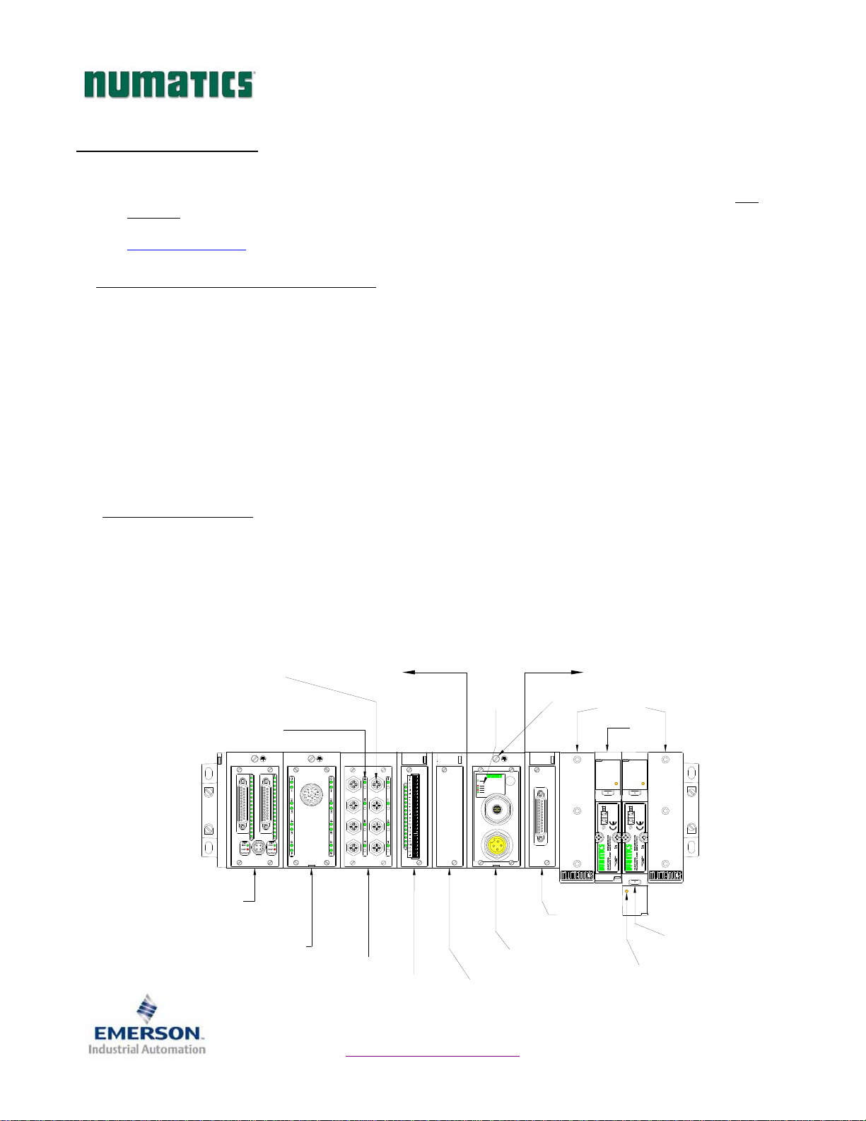
Below is an example of a 2012 series valve manifold. This fieldbus manifold series is capable of addressing a
total of 128 I/O (up to 1 full rack size). The manifold can be viewed as having two sections to it, the
Side
and the
I/O Side
connectors: a 5-pin communication connector and a 4-pin power connector. Pin-outs for these, along with
I/O connectors, and are labeled on the side of the respective modules.
supports a maximum of 6 modules totaling 110 I/O. The communication module has two
or may be ordered by calling 248-887-4111.
Discrete I/O Side
Discrete I/O
Connectors
I/O Point
LED Status
Indicator(s)
. The
Valve Side
Discrete I/O Side
(Maximum of 6 Modules)
supports a maximum of 32 solenoid coils and the
Valve Side
Chassis Ground
Connection
Valve
End Plates
Module/
Network
Status LED's
(Maximum of 32 Solenoids)
Valve
Discrete
Valve
Dual 25 Pin Sub-D
w/Aux Power
Output Module
Page 1
19 Pin Round
Connector Module
8 Connector I/O Module
Terminal Strip Module
3835050 TDG22ABQS3-0 1/07
Subject to change without notice
www.numatics.com/fieldbus
COMM. STATUS
A-B
1771 RIO
FUSE 1
+24V VLV/OUT
FUSE 2
+24V NODE/IN
Communications
Module (Node)
Manual Configuration
Module (MCM)
Valve Side
Sub-D Output
Module
Manual
Override
Solenoid LED
Status Indicator
G2-2 Series A-B 1771 Remote I/O
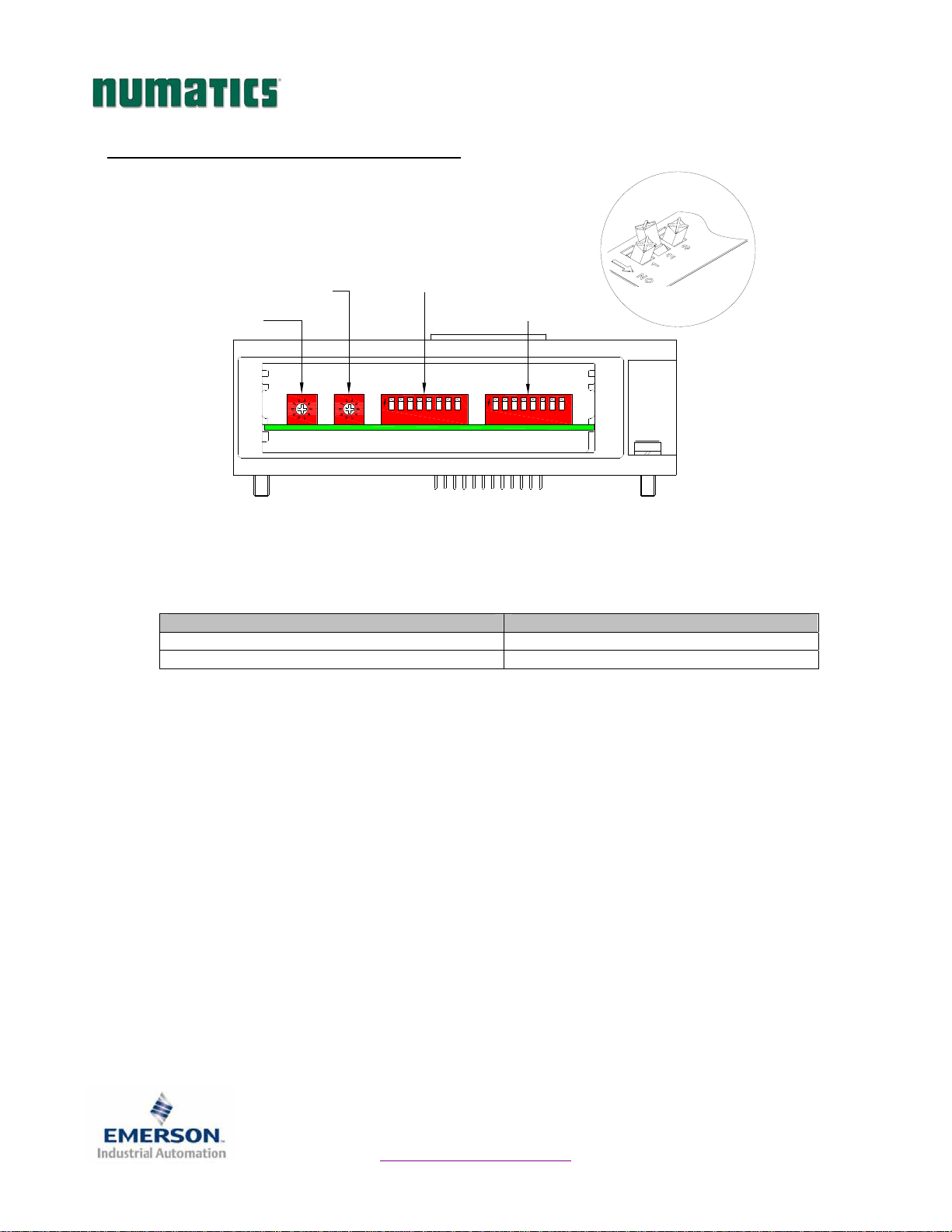
3) MCM - Manual Configuration Module
Rotary Switch
(SW3)
Rotary Switch
(SW4)
All DIP switches shown in the "OFF" position
The MCM is the module that allows the user to manually set baud rate, rack address and other user definable
options. The MCM consists of two DIP switch sets (SW1 and SW2) and two rotary switches (SW3 and SW4).
MCM Module Part Numbers
Description Part Number
Complete Module 239-1384
Replacement Board 256-684
DIP Switch
(SW2)
4
325
1
ON
6
7
Quick Start Manual
DIP Switch
(SW1)
4
5
ON
3
1
2
678
8
3835050 TDG22ABQS3-0 1/07
Subject to change without notice
Page 2
www.numatics.com/fieldbus
G2-2 Series A-B 1771 Remote I/O
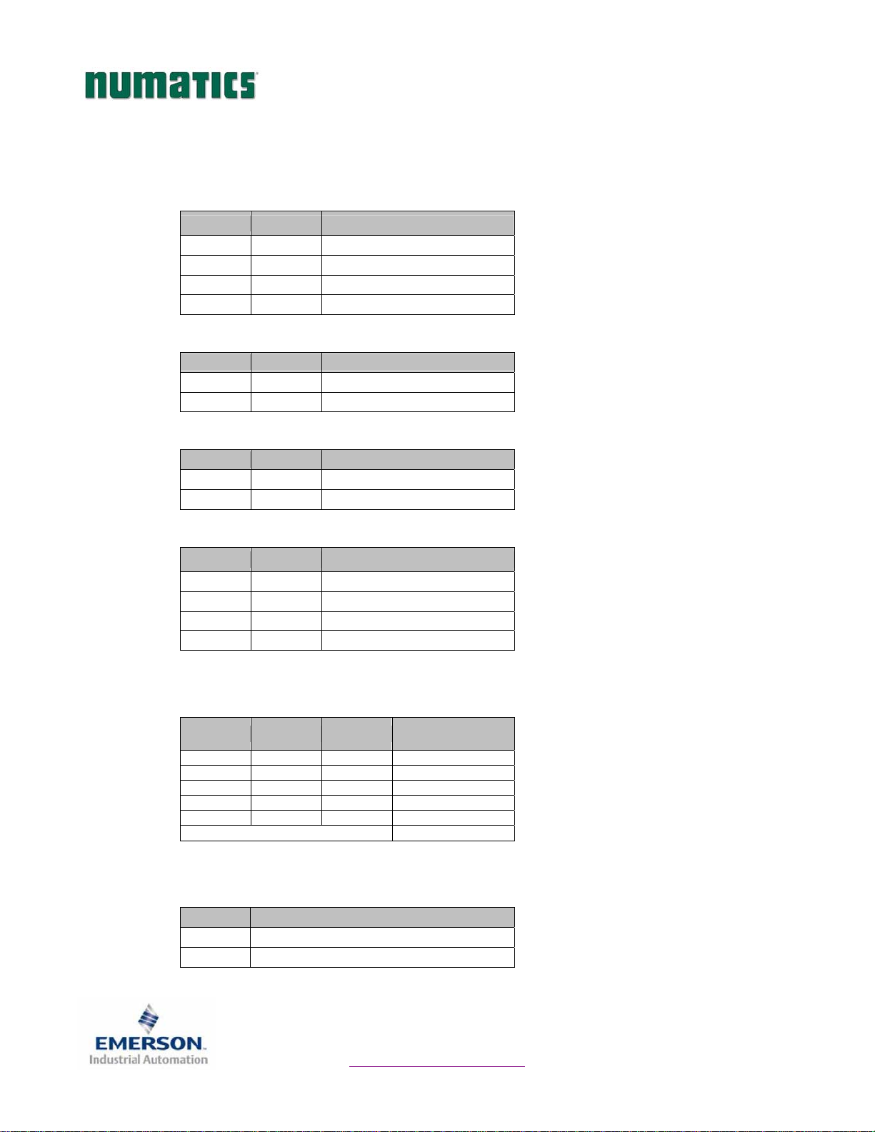
MCM Settings
DIP Switch Settings (SW1)
DIP Switch Settings (SW2)
Rotary Switch Settings (SW3 and SW4)
Baud Rate:
Quick Start Manual
SW1-1 SW1-2 Kbaud
Off* Off* 57.6*
Off On 115.2
On Off 230.4
On On 230.4
Processor Restart/Lockout:
Switch Setting Description
SW1-5 Off* Processor Restart
SW1-5 On Processor Lockout
Hold Last State:
Switch Setting Description
SW1-6 Off* Reset Outputs
SW1-6 On Hold Last State
Starting Quarter:
SW1-7 SW1-8 Quarter
Off* Off* 1
st
*
Off On 2nd
On Off 3rd
On On 4th
Valve Output Configuration (Allocated Valve Coil Outputs):
SW2-6 SW2-7 SW2-8
Off* Off* Off* 32 Coils
Off Off On 24 Coils
Off On Off 16 Coils
Off On On 8 Coils
On Off Off 0 Coils
Any Other Setting 32 Coils
Valve Coil
Outputs
Rack Address (Decimal):
Switch Description
SW3 Sets the Ones Digits
SW4 Sets the Tens Digits
* Factory Default Settings
3835050 TDG22ABQS3-0 1/07
Subject to change without notice
Page 3
www.numatics.com/fieldbus
T
G2-2 Series A-B 1771 Remote I/O
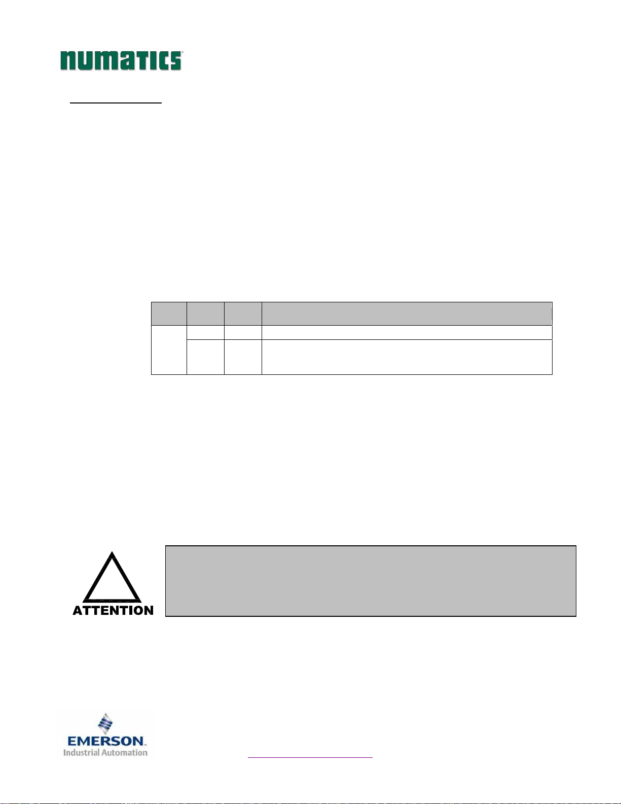
4) Self-Test Mode
An internal diagnostic tool can also be enabled using the optional MCM module. This tool allows the user to
confirm that all of the Inputs and Outputs on the manifold are fully functional without needing a network
connection or controller. There are two test modes that the user can choose using SW2-8. The “Output” test
mode tests all the outputs by sequentially turning them ON one at a time. The “Input/Output” test mode
tests the inputs by causing all of the outputs to toggle between even and odd values when any input is made.
To use the Self-Test Mode, the user must first set some initial conditions using the MCM module. Follow
these steps to obtain the needed initial condition settings. Remember to remove power from the manifold
before making changes to the MCM when setting these initial conditions.
1) Disconnect power and air from the manifold!
2) Record current MCM settings.
3) Set the rotary switches to 99 (SW3 and SW4).
4) Make sure that SW1-5, SW2-1, and SW2-7 are in the “ON” position.
5) Select the desired test mode with SW2-8 (see table below)
Switch
SW2-8
6) Make sure that all of the other switches are in the “OFF” position.
The initial conditions are now set. To enable the Self-Test Mode, apply power to the manifold and make the
following changes within 5 to 10 seconds:
Self-Test Mode is terminated by removing power to the unit. Remember to return the MCM settings to their
original settings to return the communication node to normal operation.
!
Quick Start Manual
esting
Mode
Output Off Sequentially turns all the outputs ON and OFF.
Input/
Output
Setting Description
Causes all of the odd outputs to come on and stay on until an
On
1) Set SW2-6 to the “ON” position.
2) Set SW2-7 to the “OFF” position.
input is made. When an input is made, the outputs will toggle to
the even outputs.
Air should be disconnected to the manifold when attempting to run the
Self-Test Mode to prevent unwanted motion.
Communication lines should be disconnected before attempting to run the
Self-Test Mode.
3835050 TDG22ABQS3-0 1/07
Subject to change without notice
Page 4
www.numatics.com/fieldbus
G2-2 Series A-B 1771 Remote I/O
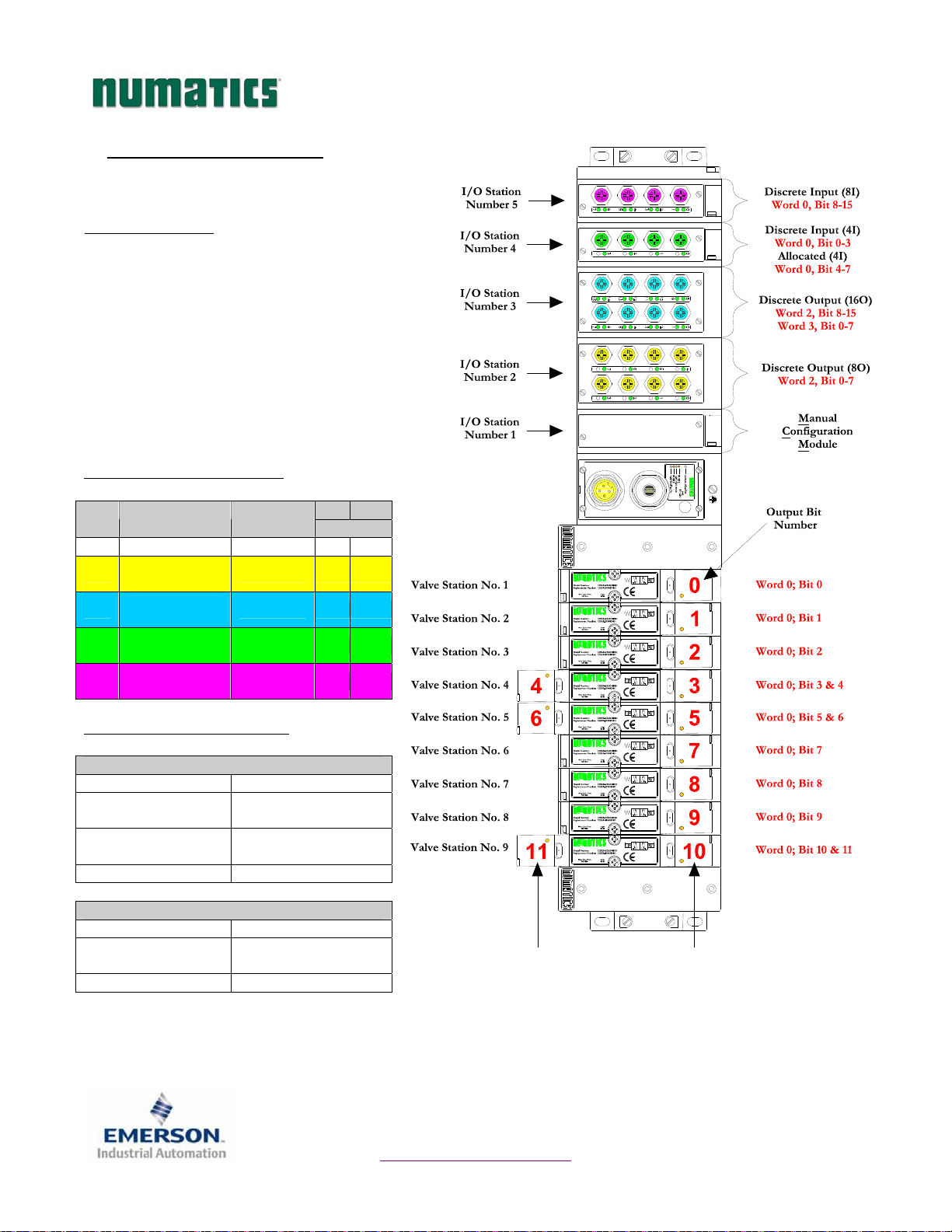
5) I/O Mapping Example
Example:
Assumed Settings
- Single Z-Boards
valves
- Double Z-Boards
solenoid valves
- Manifold I/O Size = ½ Rack
- Starting Quarter = 1st
- Valve Output Configuration = 32 Coils
Discrete I/O Configuration
Module Type Part No.
No.
1 MCM 239-1384 -- --
8O Sourcing
2
3
4
5
(PNP)
16O Sourcing
(PNP)
4I Sinking
(NPN)
8I Sinking
(NPN)
Manifold I/O Configuration
Outputs and Mapping Location
Valve Outputs = 12 Word 0; Bits 0-11
Allocated Unused
Valve Outputs = 20
Discrete
Outputs = 24
Total Outputs = 56
Inputs and Mapping Location
Discrete Inputs = 12 Word 0; Bits 0-3, 8-15
Allocated and
Reserved Inputs = 4
Total Inputs = 16
TM
used with single solenoid
TM
used with double
In OutPos
Bits
239-1315 -- 8
239-1319 -- 16
239-1304 4 --
239-1308 8 --
Word 0; Bits 12-15
Word 1; Bits 0-15
Word 2; Bits 0-15
Word 3; Bits 0-7
Word 0; Bits 4-7
Quick Start Manual
When the 12 End
Solenoid is
energized, the 2 port
is pressurized.
When the 14 End
Solenoid is
energized, the 4 port
is pressurized.
3835050 TDG22ABQS3-0 1/07
Subject to change without notice
Page 5
www.numatics.com/fieldbus
G2-2 Series A-B 1771 Remote I/O
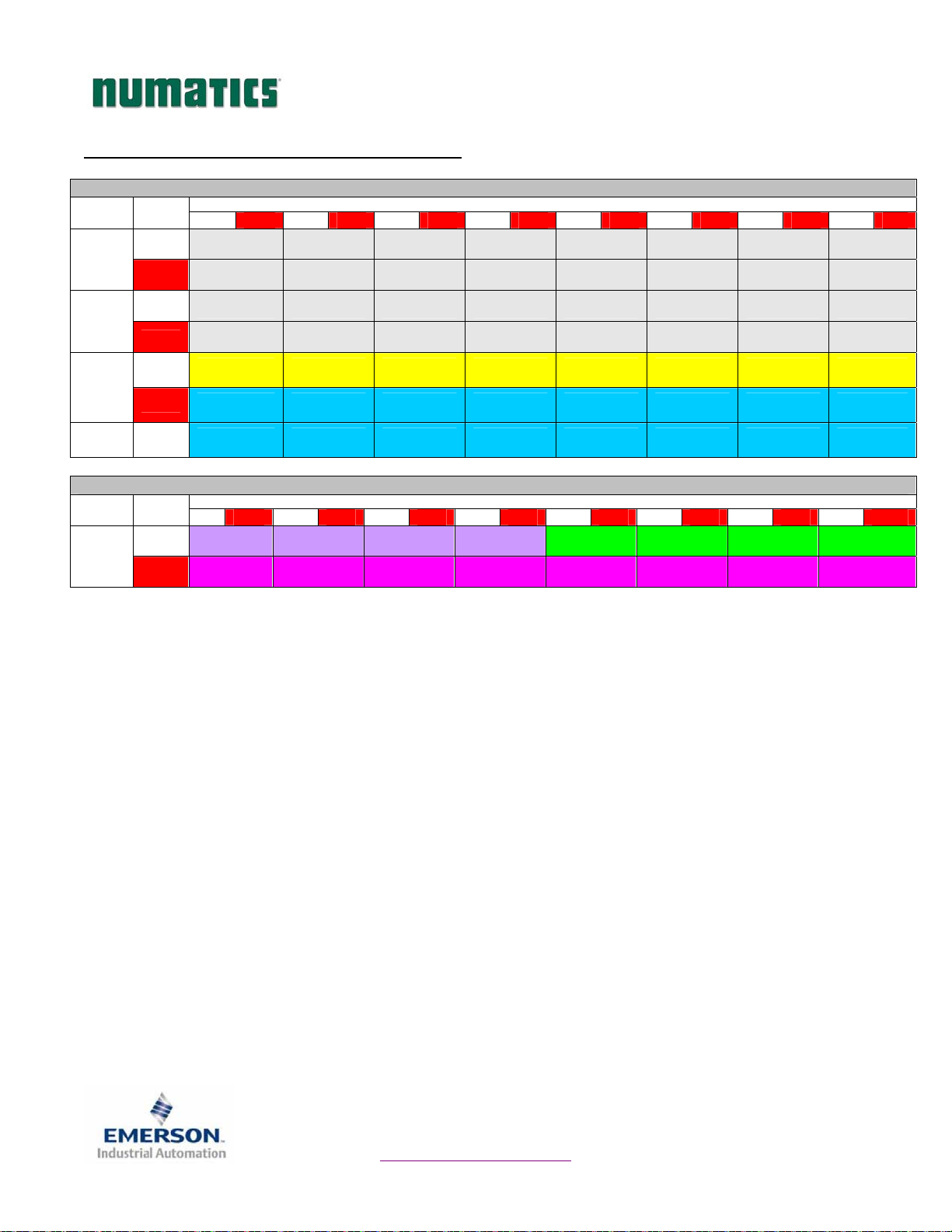
I/O Mapping Table Example Continued
WORD BYTE
0
0
1
2
1
3
4
2
5
3 6
WORD BYTE
0
0
1
7 15 6 14 5 13 4 12 3 11 2 10 1 9 0 8
Valve Coil
No. 8
Allocated &
Reserved
Allocated &
Reserved
Allocated &
Reserved
Discrete
Output No. 7
Discrete
Output No. 7
Discrete
Output No. 15
Valve Coil
No. 7
Allocated &
Reserved
Allocated &
Reserved
Allocated &
Reserved
Discrete
Output No. 6
Discrete
Output No. 6
Discrete
Output No. 14
Valve Coil
No. 6
Allocated &
Reserved
Allocated &
Reserved
Allocated &
Reserved
Discrete
Output No. 5
Discrete
Output No. 5
Discrete
Output No. 13
7 15 6 14 5 13 4 12 3 11 2 10 1 9 0 8
Allocated &
Reserved
Discrete
Input No. 7
Allocated &
Reserved
Discrete
Input No. 6
Allocated &
Reserved
Discrete
Input No. 5
Quick Start Manual
Output Table
BIT
Valve Coil
No. 5
Allocated &
Reserved
Allocated &
Reserved
Allocated &
Reserved
Discrete
Output No. 4
Discrete
Output No. 4
Discrete
Output No. 12
Input Table
Allocated &
Reserved
Discrete
Input No. 4
Output No. 11
BIT
Input No. 3
Input No. 3
Valve Coil
No. 4
Valve Coil
No. 12
Allocated &
Reserved
Allocated &
Reserved
Discrete
Output No. 3
Discrete
Output No. 3
Discrete
Discrete
Discrete
Input No. 2
Input No. 2
Valve Coil
No. 3
Valve Coil
No. 11
Allocated &
Reserved
Allocated &
Reserved
Discrete
Output No. 2
Discrete
Output No. 2
Discrete
Output No. 10
Discrete
Discrete
Valve Coil
No. 2
Valve Coil
No. 10
Allocated &
Reserved
Allocated &
Reserved
Discrete
Output No. 1
Discrete
Output No. 1
Discrete
Output No. 9
Discrete
Input No. 1
Discrete
Input No. 1
Valve Coil
No. 1
Valve Coil
No. 9
Allocated &
Reserved
Allocated &
Reserved
Discrete
Output No. 0
Discrete
Output No. 0
Discrete
Output No. 8
Discrete
Input No. 0
Discrete
Input No. 0
3835050 TDG22ABQS3-0 1/07
Subject to change without notice
Page 6
www.numatics.com/fieldbus
 Loading...