

Page 1
Instruction Manual
760007-A
July 2003
Model NGA2000 PMD
Paramagnetic Detector Analyzer Module
http://www.processanalytic.com
Page 2

ESSENTIAL INSTRUCTIONS
READ THIS PAGE BEFORE PROCEEDING!
Rosemount Analytical designs, manufactures and tests its products to meet many national and international standards. Because these instruments are sophisticated technical products, you MUST properly
install, use, and maintain them to ensure they continue to operate within their normal specifications.
The following instructions MUST be adhered to and integrated into your safety program when installing,
using, and maintaining Rosemount Analytical products. Failure to follow the proper instructions may
cause any one of the following situations to occur: Loss of life; personal injury; property damage; damage
to this instrument; and warranty invalidation.
• Read all instructions
prior to installing, operating, and servicing the product.
• If you do not understand any of the instructions, contact your Rosemount Analytical representative
for clarification.
• Follow all warnings, cautions, and instructions
marked on and supplied with the product.
• Inform and educate your personnel in the proper installation, operation, and maintenance of
the product.
• Install your equipment as specified in the Installation Instructions of the appropriate Instruc-
tion Manual and per applicable local and national codes. Connect all products to the proper elec-
trical and pressure sources.
• To ensure proper performance, use qualified personnel
to install, operate, update, program, and
maintain the product.
• When replacement parts are required, ensure that qualified people use replace ment parts specified by
Rosemount. Unauthorized parts and procedures can affect the product’s performance, place the safe
operation of your process at risk, and VOID YOUR WARRANTY
. Look-alike substitutions may result
in fire, electrical hazards, or improper operation.
• Ensure that all equipment doors are closed and protective covers are in place, except when
maintenance is being performed by qualified persons, to prevent electrical shock and personal
injury.
The information contained in this document is subject to change without notice.
Viton-A® is a registered trademark of E.I. duPont de Nemours & Co.
Paliney No. 7™ is a trademark of J.M. Ney Co.
Emerson Process Management
Rosemount Analytical Inc.
Process Analytic Division
1201 N. Main St.
Orrville, OH 44667-0901
T (330) 682-9010
F (330) 684-4434
e-mail: gas.csc@EmersonProcess.com
http://www.processanalytic.com
Page 3

Model NGA2000 PMD
TABLE OF CONTENTS
PREFACE...........................................................................................................................................P-1
Intended Use Statement.....................................................................................................................P-1
Definitions...........................................................................................................................................P-1
Safety Summary.................................................................................................................................P-2
General Precautions For Handling And Storing High Pressure Gas Cylinders .................................P-4
Documentation....................................................................................................................................P-5
Compliances.......................................................................................................................................P-5
Glossary Of Terms ...........................................................................................................................P-6
1-0 DESCRIPTION AND SPECIFICATIONS..............................................................................1-1
1-1
Overview................................................................................................................................1-1
1-2 Typical Applications...............................................................................................................1-1
1-3 Theory Of Technology...........................................................................................................1-1
1-4 Features.................................................................................................................................1-2
1-5 Specifications.........................................................................................................................1-3
a. General ...........................................................................................................................1-3
b. Sample............................................................................................................................1-3
c. Physical...........................................................................................................................1-3
Instruction Manual
760007-A
July 2003
2-0 INSTALLATION ....................................................................................................................2-1
2-1 Unpacking..............................................................................................................................2-1
2-2 Assembly...............................................................................................................................2-1
2-3 Location.................................................................................................................................2-2
2-4 Gases ....................................................................................................................................2-2
a. Requirements..................................................................................................................2-2
b. Connections....................................................................................................................2-3
c. Leak Test ........................................................................................................................2-3
2-5 Electrical Connections...........................................................................................................2-6
3-0 OPERATION .........................................................................................................................3-1
3-1 Overview................................................................................................................................3-1
3-2 Displays.................................................................................................................................3-1
a. Run Mode Display...........................................................................................................3-1
b. Menu Displays.................................................................................................................3-1
c. Help Displays..................................................................................................................3-1
3-3 Startup Procedure .................................................................................................................3-5
3-4 Binding...................................................................................................................................3-5
3-5 Calibration..............................................................................................................................3-5
3-6 Background Gas Compensation ...........................................................................................3-8
3-7 Barometric Pressure Compensation .....................................................................................3-11
4-0 MAINTENANCE AND SERVICE ..........................................................................................4-1
4-1 Overview................................................................................................................................4-1
4-2 Printed Circuit Board Replacement.......................................................................................4-1
4-3 Module Fan Replacement.....................................................................................................4-2
4-4 Thermal Fuse Replacement..................................................................................................4-3
4-5 Flow Sensor Replacement ....................................................................................................4-4
4-6 Power Fuse Replacement.....................................................................................................4-4
Rosemount Analytical Inc. A Division of Emerson Process Management Contents i
Page 4

Instruction Manual
760007-A
July 2003
5-0 REPLACEMENT PARTS......................................................................................................5-1
5-1 Matrix.....................................................................................................................................5-1
5-2 Replacement Parts................................................................................................................5-2
6-0 RETURN OF MATERIAL......................................................................................................6-1
6-1 Return Of Material.................................................................................................................6-1
6-2 Customer Service..................................................................................................................6-1
6-3 Training..................................................................................................................................6-1
7-0 APPENDIX A. MENU DISPLAYS.........................................................................................7-1
Figure 1-1. Spherical Body in Non-Uniform Magnetic Field..................................................... 1-1
Figure 1-2. Trace Oxygen Detector Coulometric Principle........................................................ 1-2
Figure 2-1. Analyzer Module Installation Into Instrument Platform.......................................... 2-1
Figure 2-2. PMD Front Panel Connections.............................................................................. 2-4
Figure 2-3. PMD Back Panel Connections............................................................................... 2-4
Figure 2-4. Interconnection of Typical Gas Manifold to PMD Analyzer Module ...................... 2-5
Figure 2-5. PMD Wiring Diagram............................................................................................. 2-6
Figure 2-6. PMD Outline and Mounting Dimensions................................................................ 2-7
Figure 3-1. Run Mode Display ................................................................................................. 3-3
Figure 3-2. Main Menu Display ................................................................................................ 3-3
Figure 3-3. Basic Controls Menu.............................................................................................. 3-3
Figure 3-4. Expert Controls and Setup Menu........................................................................... 3-4
Figure 3-5. Technical Level Configuration Menu..................................................................... 3-4
Figure 3-6. Typical Help Screen............................................................................................... 3-4
Figure 4-1. PMD Module – Major Components ....................................................................... 4-1
Figure 4-2. Module Fan Assembly........................................................................................... 4-2
Figure 4-3. Detector Assembly................................................................................................. 4-3
Model NGA2000 PMD
LIST OF ILLUSTRATIONS
LIST OF TABLES
Table 3-1. PMD Analyzer Module Alarms............................................................................... 3-2
Table 3-2. Calibration Range for Various Zero Based Operating Ranges ............................. 3-6
Table 3-3. Calibration Range for Various Suppressed Range Operations.............................3-6
Table 3-4. Oxygen Equivalents of Common Gases.............................................................. 3-10
ii Contents Rosemount Analytical Inc. A Division of Emerson Process Management
Page 5
Instruction Manual
Model NGA2000 PMD
PREFACE
INTENDED USE STATEMENT
The purpose of this manual is to provide information concerning the components, functions, installation and
maintenance of the Model NGA2000 PMD and the System Accessories of the NGA2000 System.
DEFINITIONS
The following definitions apply to DANGERS, WARNINGS, CAUTIONS and NOTES found throughout
this publication.
DANGER .
Highlights the presence of a hazard which will cause severe personal injury, death, or substantial
property damage if the warning is ignored.
760007-A
July 2003
WARNING .
Highlights an operation or maintenance procedure, practice, condition, statement, etc. If not
strictly observed, could result in injury, death, or long-term health hazards of personnel.
CAUTION.
Highlights an operation or maintenance procedure, practice, condition, statement, etc. If not
strictly observed, could result in damage to or destruction of equipment, or loss of effectiveness.
NOTE
Highlights an essential operating procedure,
condition or statement.
Rosemount Analytical Inc. A Division of Emerson Process Management Preface P-1
Page 6

Instruction Manual
760007-A
July 2003
Model NGA2000 PMD
SAFETY SUMMARY
Some sections may describe equipment not used in your configuration. The user should become thoroughly familiar with the operation of this module before operating it. Read this instruction manual completely.
DANGER.
ELECTRICAL SHOCK HAZARD
Do not operate without covers secure. Servicing requires access to live parts which can cause
death or serious injury. Refer servicing to qualified personnel.
For safety and proper performance this instrument must be connected to a properly grounded
three-wire source of power.
DANGER.
POSSIBLE EXPLOSION HAZARD
This equipment is not designed and should not be used in the analysis of flammable samples. Use
of this equipment in this way could result in explosion and death.
NOTE
Apply leak test liquid to cell or detectors only as a last resort.
WARNING
POSSIBLE EXPLOSION HAZARD
Verify that all gas connections are made as labeled and are leak free. Improper gas connections
could result in explosion or death. See Section 2-4c on page 2-3 for Leak test procedure.
WARNING.
HIGH PRESSURE GAS CYLINDERS
This analyzer requires use of pressurized gas. See General Precautions for Handling and Storing
High Pressure Cylinders, page P-4.
WARNING.
PARTS INTEGRITY
Tampering or unauthorized substitution of components may adversely affect safety of this product.
Use only factory documented components for repair.
P-2 Preface Rosemount Analytical Inc. A Division of Emerson Process Management
Page 7

Instruction Manual
Model NGA2000 PMD
WARNING
OVER-VOLTAGE SPIKING
If this Analyzer Module is used with a non-Rosemount Analytical po wer supply, adding Rosemo unt
Analytical PN 90331 Current Protector in series with the 24 V positive line will prevent over-voltage
spiking and resultant fuse flowing when powering up the instrument.
CAUTION
HAND INJURY HAZARD
Do not place hands or fingers in Platform front handles when the front panel is open. Dropping
front panel while hand or fingers are inside either handle can cause serious injury.
CAUTION
OVERBALANCE HAZARD
760007-A
July 2003
This Analyzer Module may tip instrument over if it is pulled out too far and the Platform is not properly supported.
NOTICE
Software compatibility is necessary for all NGA2000 components in your system to work together.
The version of your Platform's software must be equal to or greater that the version of any other
module(s) for successful compatibility. If it is not, contact Rosemount Analytical at 800-433-6076 to
order software upgrade kit PN 657150 for the Platform.
You can locate the version of each NGA2000 component as follows:
Platform Controller Board
Turn power ON.
The display will show "Control Module V2. ...". This is the software version.
Analyzer Module
Located on the right side of the Analyzer Module case.
I/O Module
Located on the backplane connector of the module. If no label is present, the module is Version
2.0.
Rosemount Analytical Inc. A Division of Emerson Process Management Preface P-3
Page 8

Instruction Manual
760007-A
July 2003
Model NGA2000 PMD
GENERAL PRECAUTIONS FOR HANDLING AND STORING HIGH
PRESSURE GAS CYLINDERS
Edited from selected paragraphs of the Compressed Gas Association's "Handbook of Compressed Gases" published in 1981
Compressed Gas Association
1235 Jefferson Davis Highway
Arlington, Virginia 22202
Used by Permission
1. Never drop cylinders or permit them to strike each other violently.
2. Cylinders may be stored in the open, but in such cases, should be protected against extremes of
weather and, to prevent rusting, from the dampness of the ground. Cylinders should be stored in the
shade when located in areas where extreme temperatures are prevalent.
3. The valve protection cap should be left on each cylinder until it has been secured against a wall or
bench, or placed in a cylinder stand, and is ready to be used.
4. Avoid dragging, rolling, or sliding cylinders, even for a short distance; they should be moved by using a
suitable hand-truck.
5. Never tamper with safety devices in valves or cylinders.
6. Do not store full and empty cylinders together. Serious suckback can occur when an empty cylinder is
attached to a pressurized system.
7. No part of cylinder should be subjected to a temperature higher than 125
never be permitted to come in contact with any part of a compressed gas cylinder.
8. Do not place cylinders where they may become part of an electric circuit. When electric arc welding,
precautions must be taken to prevent striking an arc against the cylinder.
°
F (52°C). A flame should
P-4 Preface Rosemount Analytical Inc. A Division of Emerson Process Management
Page 9
Instruction Manual
9
6
Model NGA2000 PMD
DOCUMENTATION
The following NGA2000 PMD instruction materials are available. Contact Customer Service Center or
the local representative to order.
760007 Instruction Manual (this document)
COMPLIANCES
This product may carry approvals from several certifying agencies, including Factory Mutual and the Canadian Standards Association (which is also an OSHA accredited, Nationally Recognized Testing Laboratory), for use in non-hazardous, indoor locations.
760007-A
July 2003
Rosemount Analytical Inc. has satisfied all obligations from the European Legislation to harmonize the
product requirements in Europe.
These products comply with the standard level of NAMUR EMC. Recommendation (May 1993).
This product satisfies all obligations of all relevant standards of the EMC framework in Australia and New
Zealand.
NRTL /C
®
97-C219
NAMUR
N
Rosemount Analytical Inc. A Division of Emerson Process Management Preface P-5
Page 10

Instruction Manual
760007-A
July 2003
Model NGA2000 PMD
GLOSSARY OF TERMS
Analyzer Module
The module that contains all sensor/detector components for development of a Primary Variable signal; includes all signal conditioning and temperature control circuitry.
Backplane
The interconnect circuit board which the Controller Board, Power Supply, Analyzer Module power and network cables, I/O Modules and Expansion Modules plug into.
Control Module
The Operator Interface plus the Controller Board.
Controller Board
The computer board that serves as the Network Manager and operates the Display and Keypad.
Distribution Assembly
The Backplane and the card cages that hold I/O and Expansion Modules.
Expansion Module
A circuit board that plugs into the Backplane from the front of the Platform and performs special features
not related to I/O functions.
I/O Module
A circuit board that plugs into the Backplane from the rear of the Platform. Has a connector terminal for
communication with external data acquisition devices and provides an input/output function.
Operator Interface
The Display and Keyboard.
Platform
Any workable collection of the following: Controller Board, Power Supply, Distribution Assembly, Enclosure
and Operator Interface.
Power Supply
Any of a variety of components that provides conditioned power to other NGA2000 components, from the
Power Supply Board that plugs into the front of the Backplane in a stand-alone instrument to several larger
ones that can power larger collections of modules and components.
Primary Variable
The measured species concentration value from an Analyzer Module.
Secondary Variable
Data placed on the network by a module regarding current status, e.g., sample flow, source voltage and
other diagnostic information.
P-6 Preface Rosemount Analytical Inc. A Division of Emerson Process Management
Page 11

Instruction Manual
Model NGA2000 PMD
Softkeys
The five function softkeys located below the front panel display; they assume the function displayed directly
above each on the display, a function dictated by software.
System
Any collection of Analyzer Module(s), Platform(s), I/O Module(s) and Expansion Module(s).
760007-A
July 2003
Rosemount Analytical Inc. A Division of Emerson Process Management Preface P-7
Page 12

Instruction Manual
760007-A
July 2003
Model NGA2000 PMD
P-8 Preface Rosemount Analytical Inc. A Division of Emerson Process Management
Page 13

Model NGA2000 PMD
DESCRIPTION AND SPECIFICATIONS
Instruction Manual
760007-A
July 2003
SECTION 1
1-1 OVERVIEW
This manual describes the Paramagnetic Detector (PMD) Analyzer Module of Rosemount
Analytical's NGA2000 Series of gas analysis
components.
The PMD Analyzer Module is designed to
continuously determine the concentration of
oxygen in a flowing gaseous mixture. The
concentration is expressed in ppm or percent
volume O
2.
The entire Analyzer Module is designed as a
slide-in module (if configured in stand-alone
instrument fashion), removable from the front
of the Platform, with gas connections made
from the rear. All electronics relative to sample detection and conditioning are included in
this module.
1-2 TYPICAL APPLICATIONS
PMD Analyzer Module applications include:
• process control
• continuous emissions monitoring sy st ems
(CEMS)
• industrial gas production
• fermentation process monitoring
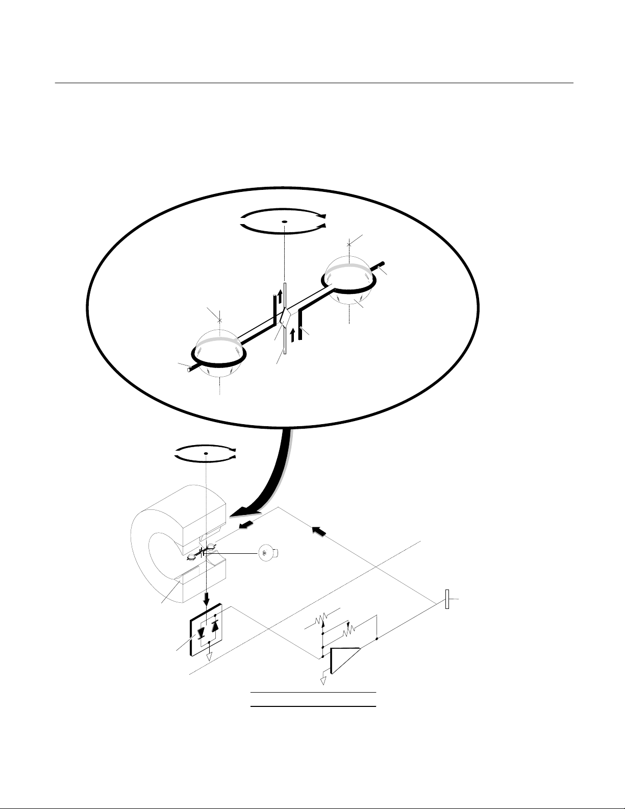
1-3 THEORY OF TECHNOLOGY
Oxygen is strongly paramagnetic (i.e., capable of becoming a temporary magnet when
placed in a magnetic field) while most other
common gases are weakly diamagnetic (i.e.,
tend to be non-magnetic). See Figure 1-1
below.
The Magnetic susceptibility of the flowing gas
sample is sensed in the detector/magnet assembly. As shown in Figure 1-2 on page 1-2,
a dumbbell shaped, nitrogen-filled, hollow gas
test body is suspended on a platinum/nickel
alloy ribbon in a non-uniform magnetic field.
Because of a "magnetic buoyancy" effect, the
spheres of the test body are subjected to displacement forces, resulting in a displacement
torque proportional to the magnetic susceptibility of the gas surrounding the test body.
Measurement is accomplished by a nullbalance system, whereby the displacement
torque is opposed by an equal and opposite
restorative torque. The restoring current is
automatically maintained at the correct level
by an electro-optical feedback system. A
beam of light from the source LED is reflected
off the square mirror attached to the test body
onto a bi-cell (dual photodiode).
The current required to keep the test body to
the null position is a linear function of the total
magnetic susceptibility of the sample gas.
See Figure 4-1 on page 4-1, Figure 4-2 on
page 4-2, and Figure 4-3 on page 4-3 for
component configuration.
Shaded
Pole
Piece
Sphere
(Magnetic Susceptibility = ko )
F
k
Sample Gas
(Magnetic Susceptibility = k )
As percentage of oxygen in sample gas increases,
displacement force (F
Note:
) increases.
k
Figure 1-1. Spherical Body in Non-Uniform
Magnetic Field
Rosemount Analytical Inc. A Division of Emerson Process Management Description and Specifications 1-1
Page 14
Instruction Manual
q
A
A
q
SS
760007-A
July 2003
Model NGA2000 PMD
1-4 FEATURES
Among the features incorporated into the
PMD Analyzer Module is a flow splitter (≈2:1)
that allows for greater sample flow, decreased
lag time and faster analyzer response.
Balancing
Weight
Electromagnetic
xis
Displacement
Restoring
Current
Restoring
Current
Current Loop
Mirror
Platinum/Nickel Alloy
Suspension Ribbon
TEST BODY DETAIL
Tor
Restoring
Torque
The "Time Alignment" feature can be used to
delay sending the Primary Variable from the
PMD Analyzer Module for up to 30 seconds in
0.1 second intervals. This feature allows Primary Variables form more than one PMD
Analyzer Module to be "time aligned" if necessary.
ue
Electromagnetic
xis
Balancing Weight
Nitrogen-Filled Hollow Gl ass
Test Body
Shaded Pole Pieces (4)
Displacement
Tor
ue
Restoring
Torque
Magnet
Test Body
LED Source
Dual Photocell
NULL BALANCE SYSTEM
Restoring
DETECTOR/MAGNET
A
EMBLY
SIGNAL CONDITIONING
Zero
ASSEMBLY
Span
Figure 1-2. Trace Oxygen Detector Coulometric Principle
SIGNAL OUTPUT
TO NETWORK
1-2 Description and Specifications Rosemount Analytical Inc. A Division of Emerson Process Management
Page 15

Model NGA2000 PMD
Instruction Manual
760007-A
July 2003
1-5 SPECIFICATIONS
a. General
Measurement Species................... Oxygen
Ranges.......................................... 0 to 100% oxygen; four fullscale selections, including suppressed
Repeatability.................................. ±1% of fullscale (at constant temperature)
Minimum Detectable Level............ 0.01% oxygen
Noise ............................................. <1% of fullscale, peak-to-peak; <±1% for suppressed ranges
Linearity......................................... ±1% of fullscale
Response Time ............................. 0 to 90% of fullscale in 20 seconds (±2 seconds)
Drift (Zero and Span)..................... <±1% of fullscale/24 hours, <±2% of fullscale/week at constant
Effect of Temperature.................... <±1% of fullscale over any 10°C interval for rate of change no
Environment .................................. Location - Class B controlled, indoor, non-hazardous
Ambient Temperature.................... 0 to 45°C (32 to 113°F)
Effect of Flow................................. <±1% of range when sample flow rate is changed by 20 ml/min.
Power Requirements..................... 24 VDC ±5%, 50 W max.; ripple and noise: <100 mV peak-to-peak;
b. Sample
1
zero ranges in 1% increments
temperature;
<±2% of fullscale/24 hours, <±4% of fullscale/week of range for 99
to 100% (at constant temperature)
greater than 10°C per hour
line and load regulations: <±1%
Temperature.................................. Non-flammable;: 10 to 66°C (50 to 150°F)
Flow Rate ...................................... 800 to 1400 ml/min.
Exhaust Pressure.......................... -345 to 690 hPa-gauge (-5 to 10 psig)
Particles......................................... filtered to <2 microns
Dewpoint........................................ below 43°C (110°F), no entrained liquid
Materials in Contact with Sample.. Glass, 316 stainless steel, titanium, Paliney No. 7, epoxy resin, Vi-
ton A, platinum, nickel, rhodium and MgF
Sample Humidity ........................... non-condensing at ambient temperatures
c. Physical
Case Classification........................ General purpose for installation in weather-protected areas
Dimensions.................................... See Outline and Mounting Dimensions, Figure 2-6 on page 2-7
Weight ........................................... 8 kg (17.6 lbs.
Mounting........................................ Inside a Platform or custom-installed in a panel
Maximum Length of LON Cable.... 1600 m (1 mile) between Analyzer Module and Platform
1
See the Platform manual for specifications regarding Platform related components.
2
Rosemount Analytical Inc. A Division of Emerson Process Management Description and Specifications 1-3
Page 16

Instruction Manual
760007-A
July 2003
Model NGA2000 PMD
1-4 Description and Specifications Rosemount Analytical Inc. A Division of Emerson Process Management
Page 17

Model NGA2000 PMD
A
2-1 UNPACKING
Instruction Manual
760007-A
July 2003
SECTION 2
INSTALLATION
WARNING
If the Paramagnetic Analyzer Module is received as a separate unit, carefully examine
the shipping carton and contents for signs of
damage. Immediately notify the shipping carrier if the carton or contents is damaged. Retain the carton and packing material until all
components associated with the Analyzer
Module are operational.
2-2 ASSEMBLY
If the Analyzer Module requires assembly with
other components (e.g., the Platform and associated I/O Modules), do so at this time. Following the guides on the bottom left and
bottom center of the Platform, carefully slide
the Analyzer Module halfway into place.
HAND INJURY HAZARD
Do not place hands or fingers in the Platform front handles when front panel is
open. Dropping the front panel of the Platform while hand or fingers are inside either
handle can cause serious injury.
Lift the spring-loaded pins on the front of the
Analyzer Module, and carefully slide it the rest
of the distance. Secure the module in position
by releasing the pins, which seat in the available holes in the bottom of the case (see
Figure 2-1 below). If the module and Platform
are difficult to assemble, remove the module,
ensure the top cover of the module is firmly
seated on the hold-down screws, and repeat
the assembly procedure.
Install I/O Module(s) according to guidelines in
the I/O manual. After startup and calibration
have been performed, secure the front panel
with the six screws provided.
Figure 2-1. Analyzer Module Installation Into Instrument Platform
Rosemount Analytical Inc. A Division of Emerson Process Management Installation 2-1
NALYZER MODULE GUIDES
PIN SEATS
DISENGAGED FRONT PANEL
Page 18

Instruction Manual
760007-A
July 2003
Model NGA2000 PMD
2-3 LOCATION
Install the Analyzer Module in a clean, nonhazardous, weather protected, vibration free
location free from extreme temperature variations. For best results, either install the module near the sample stream to minimize
sample transport time or supply a flow greater
than necessary and route only the appropriate
amount through the Analyzer Module.
Observing these requirements are critical.
Note the following:
• Excessive vibration can cause a noisy
readout. To minimize vibration effects,
the detector/magnet assembly is enveloped in a shock-mounted compartment.
• The user should ensure, when making
any internal electrical connections, that
no cables are placed in contact with the
detector assembly or associated internal
sample inlet and outlet tubing.
An oxygen-free gas, typically nitrogen, is
required for use as the zero standard gas.
Recommendations for span calibration
gases, bases on various operating
ranges, are tabulated in Table 3-4 on
page 3-10. Air (20.93% oxygen) can be
used as span gas regardless of the
ranges used for sampling, although very
low ranges may lose accuracy.
Sample Gas
Sample gas should be non-flammable.
Temperature
Sample temperature at the inlet should be
from 50°F to 150°F (10°C to 66°C). A
maximum entry temperature of 110°F
(43°C) is recommended to prevent cooling of the sample and possible internal
condensation. Such condensation could
damage some components of the Analyzer Module. This recommendation can
be ignored if a thoroughly dry sample is
examined.
• Magnetic susceptibilities and partial
pressures of gases vary with temperature. Permissible ambient temperature
range is 32°F to 113°F (0°C to 45°C).
• The interior of the Detector Assembly is
maintained at approximately 144°F
(62°C) by an electronically controlled
heater. Prior to entering the detector
assembly, the sample is heated in a
coiled tubing to match the detector's
temperature.
2-4 GASES
a. Requirements
Calibration Gases
Analyzer Module calibration requires the
establishment of zero and span calibration points. This requires a zero standard
gas to set the zero point span gas to establish a calibration point at or near the
upper range limit.
Pressure
Sample exhaust pressure limits are -5 to
10 psig (-345 to 690 hPa-gauge). Normal
operation is in the positive range, between 0 and 10 psig (0 and 690 hPagauge). Negative gauge pressures are
not normally recommended, but may be
used in certain special applications.
To prevent over-pressurization, insert a
pressure relief valve into the sample inlet
line. A check valve should also be placed
in the outlet line if the Analyzer Module is
connected to a manifold associated with a
flare or other apparatus that does not operate at atmospheric pressure.
The outlet port is commonly vented to the
atmosphere. Any change in barometric
pressure has a directly proportional effect
on the indicated percent of oxygen, and
should be neutralized through manual or
computer correction of data. Note the following example:
2-2 Installation Rosemount Analytical Inc. A Division of Emerson Process Management
Page 19

Model NGA2000 PMD
Instruction Manual
760007-A
July 2003
Range = 0% to 5% oxygen
Barometric pressure change after
calibration = 1%
Analyzer Module measurement = 5%
oxygen
Measurement error = 0.01 x 5% oxy-
gen
Fullscale span = 5% oxygen
0.05% oxygen error = 1% of fullscale
The error is more significant for suppressed range 99% to 100%.
An optional barometric pressure
compensation board is available to
automatically perform this correction.
A general rule regarding calibration gas
pressure is that it should be the same as
the expected sample gas pressure during
routine operation.
The above requirement increases the difficulty of operation at negative gauge
pressure. A suction pump can be connected to the outlet port for drawing sample through the Analyzer Module. Such
operation necessitates special precautions to ensure accurate readout, including the following:
The need for equilibrium between sample
and gas calibration pressures.
Any leakage in the sample handling system will decrease readout accuracy.
Flow Rate
Recommended sample flow rate is 800 to
1400 ml/min., ±40 ml/min. Optimum flow
rate is 1100 ml/min.
If flow is held to within tolerance and operating pressure remains constant, zero
and span drift will meet specified limits.
b. Connections
(See Figure 2-3 on page 2-4) Connect
inlet and outlet lines for sample gas to
appropriately labeled fittings on the rear
panel. Both connections are 1/4 inch ferrule-type compression fittings.
Zero and span gases use the same inlet
and outlet as the sample. Figure 2-4 on
page 2-5 shows a typical external sample
handling manifold for gas selection. Particulates must be filtered down to two microns, gases generally require
pressurization, and flow measurement
metering MUST be present.
c. Leak Test
The Analyzer Module is thoroughly tested
at the factory for gas leakage. The user is
responsible for testing for leakage only at
the inlet and outlet fittings on the rear
panel. The user is also responsible for internal leak testing periodically and if any
internal pneumatic components are adjusted or replaced (with a test procedure
selected by the user).
Rosemount Analytical Inc. A Division of Emerson Process Management Installation 2-3
Page 20
Instruction Manual
(
)
760007-A
July 2003
Note: Reference and purge gas connections are applicable only to certain applications.
Model NGA2000 PMD
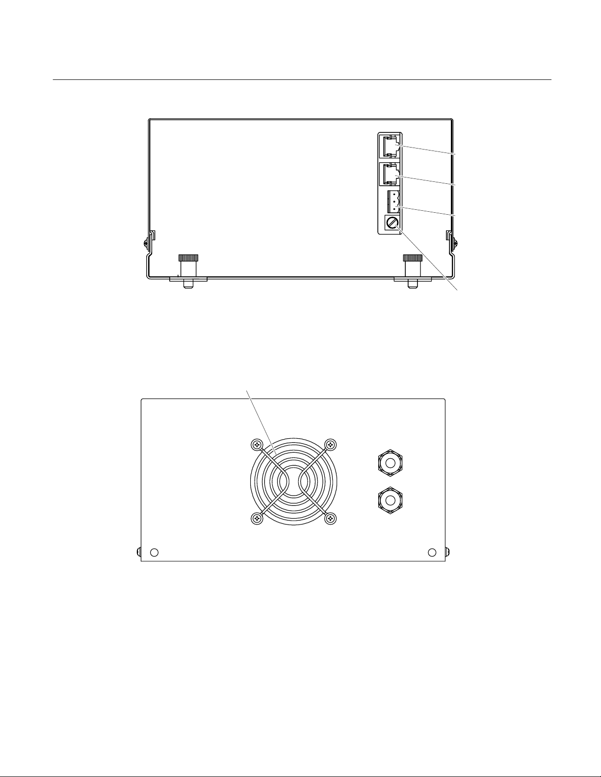
Figure 2-2. PMD Front Panel Connections
FAN
SAMPLE
10 PSI MAX
69 kPa MAX
Figure 2-3. PMD Back Panel Connections
NETWORK 1
NETWORK 2
POWER
FUSE
OUT
IN
2-4 Installation Rosemount Analytical Inc. A Division of Emerson Process Management
Page 21
Model NGA2000 PMD
Z
Instruction Manual
760007-A
July 2003
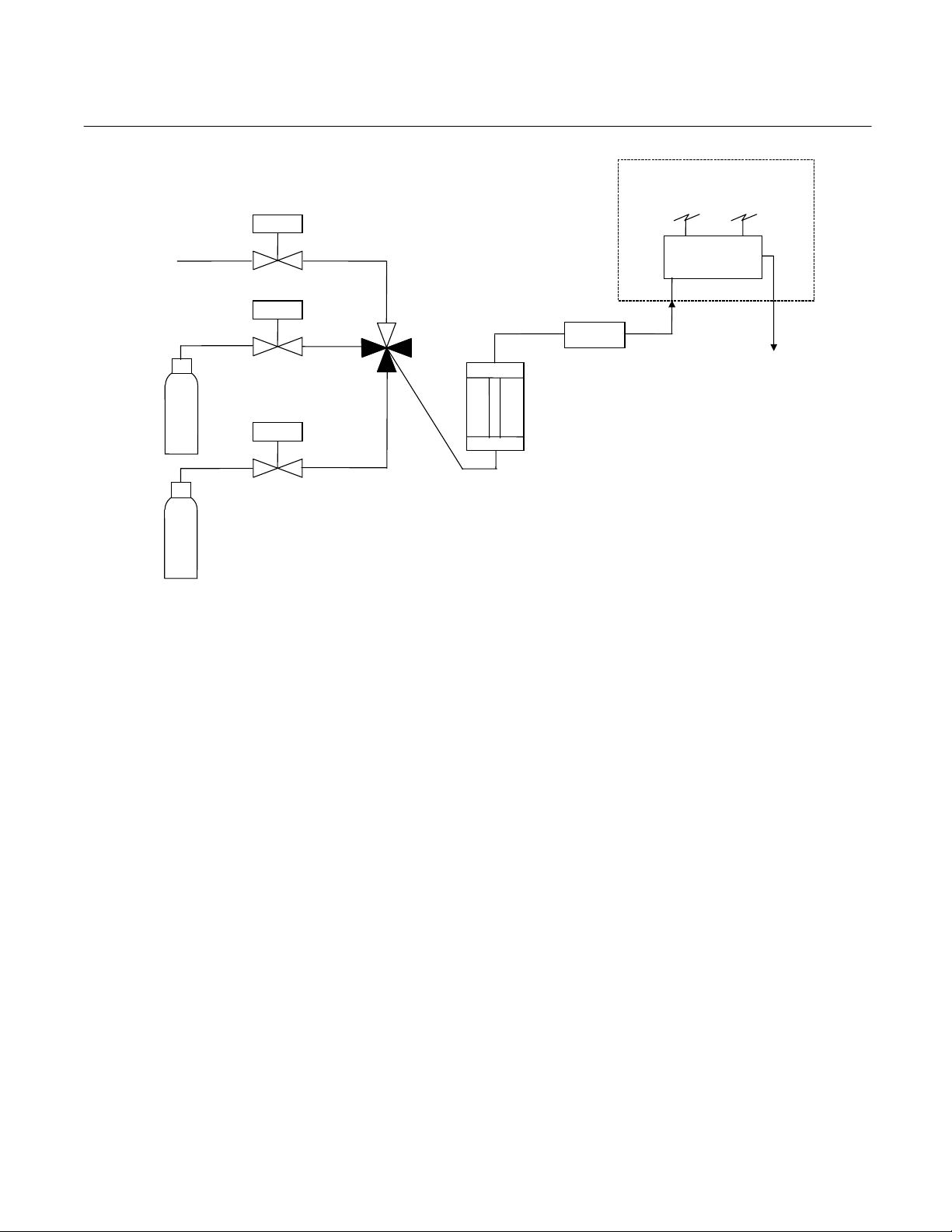
Sample In
ero
Standard
Gas
Span
Standard
Gas
PMD Analyzer
Needle
Valves
Two Micron
Filter
Flowmeter
Flow Splitter
Figure 2-4. Interconnection of Typical Gas Manifold to PMD Analyzer Module
Module
(≈2:1)
To Vent
Rosemount Analytical Inc. A Division of Emerson Process Management Installation 2-5
Page 22
Instruction Manual
760007-A
July 2003
Model NGA2000 PMD
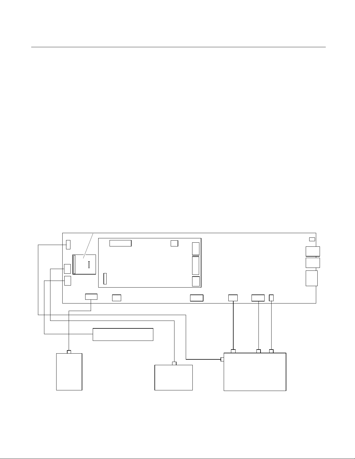
2-5 ELECTRICAL CONNECTIONS
NOTE
Electrical connections must be in compliance with National Electrical Code
(ANSI/NFPA 70) and/or any applicable national or electrical codes.
Two electrical connections are required on the
Analyzer Module; POWER and NETWORK.
J5
PRESSURE
COMPENSATION
BOARD
J6
J10
J11
J13
COMPUTER ANALYSIS
J7
J14
J19
W1
FLOW SENSOR CABLE
PREAMP CABLE ASSEMBLY
CASE TEMP SENSOR
FAN
See Figure 2-2 on page 2-4. On the Analyzer
Module, two NETWORK connections are
available, either of which is appropriate for : 1)
interconnection with Backplane of the Platform (see Platform instruction manual) or 2)
"daisy chaining" with other NGA2000 components.
Connect Analyzer Module POWER 24 VDC
power source, either the Platform or external
power source.
BOARD
J4
FLOW
SENSOR
J1
J2
J3
J16
Figure 2-5. PMD Wiring Diagram
MAIN BOARD
J20
SENSOR
ASSEMBLY
J21 J22
LED SOURCE
THERMAL CUTOFF
MAGNET HEATER AND
OPTICAL BENCH
J17
J9
J12
J15
ASSEMBLY
2-6 Installation Rosemount Analytical Inc. A Division of Emerson Process Management
Page 23
Model NGA2000 PMD
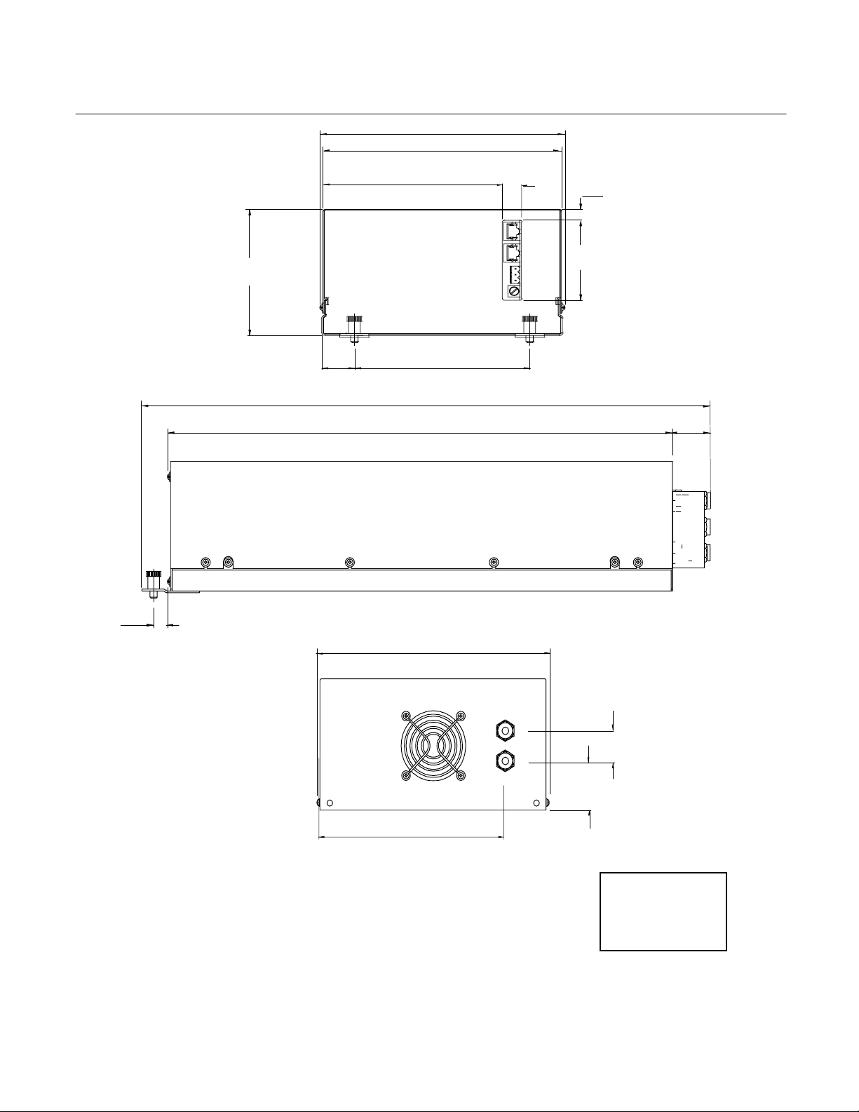
8.4
[213]
6.7
6.2
[157]
[152]
6.0
8.4
[213]
8.2
[208]
17.41
[442]
[109]
[28]
20.0
[508]
.6
[15]
E. FUSE.
D. POWER CABLE TO NETWORK.
C. NETWORK CABLE CONNECTIONS TO PLATFORM.
B. SAMPLE OUT: 1/4" O.D. TUBE FITTING.
A. SAMPLE IN: 1/4" O.D. TUBE FITTING.
5. MODULE TO BE INSTALLED WITHIN ±15° OF HORIZONTAL.
4. POWER REQUIREMENTS: 24 VDC 3.5 A.
3. ELECTRICAL INSTALLATION MUST BE IN COMPLIANCE WITH NATIONAL ELECTRICAL
CODE (ANSI/NFPA 70) AND/OR ANY APPLICABLE NATIONAL OR LOCAL CODES.
2. MODULE IS NOT WEATHERPROOF.
1. APPROXIMATE WEIGHT: 15 LB (6.8 kg).
[170]
Figure 2-6. PMD Outline and Mounting Dimensions
[15]
10 PSI MAX
2.8
[71]
[13]
1.0
[25]
1.6
[41]
DIMENSIONS
Instruction Manual
760007-A
July 2003
1.6
[40]
INCH
[mm]
Rosemount Analytical Inc. A Division of Emerson Process Management Installation 2-7
Page 24

Instruction Manual
760007-A
July 2003
Model NGA2000 PMD
2-8 Installation Rosemount Analytical Inc. A Division of Emerson Process Management
Page 25

Model NGA2000 PMD
Instruction Manual
760007-A
July 2003
SECTION 3
OPERATION
3-1 OVERVIEW
Prior to initial startup, the user should perform
the leak test procedure outlined in Section 24c on page 2-3.
For the remainder of this section Analyzer
Module interconnection with a Platform or
some interfacing component will be assumed.
Display and keypad information shall refer to
that which the user can expect to see and do
with regard to the front panel of the Platform.
For a complete description of the Platform
front panel controls and indicators, see the
Platform instruction manual, Displays & Operating Keys.
3-2 DISPLAYS
Three kinds of Display screens are available
to the user:
• Run Mode
• Menu
• Help
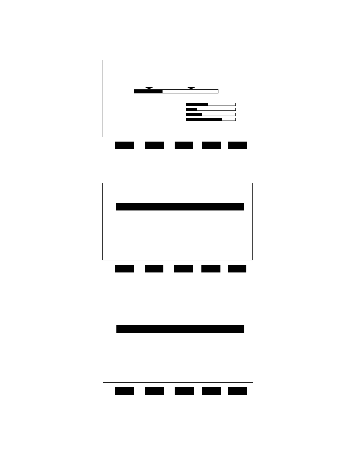
a. Run Mode Display
The Run Mode is the normal mode of operation. In this mode, the Display (see
Figure 3-1 on page 3-3) will show current
gas measurement, the component of interest, the current operations of the softkeys, and a graphic bar representing the
displayed concentration as ppm or as a
percent of oxygen.
If more than one Analyzer Module is connected to the system, the Run Mode display will show as many as four gas
measurements on screen. Alarm messages may also appear on the display
(See Table 3-1 on page 3-2).
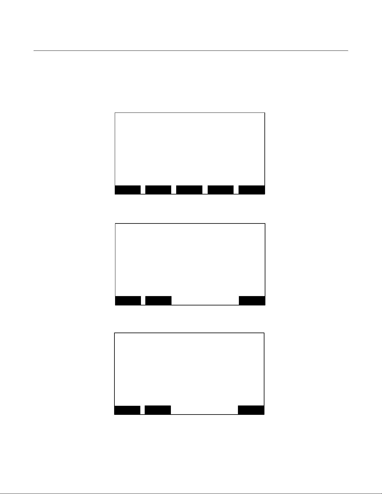
b. Menu Displays
The menu structure enables the user to
access data and functions, and put information onto the network.
The Main Menu (Figure 3-2 on page 3-3)
is subdivided into three levels of control
based generally on which personnel is
likely to use it: Basic Controls, Expert
Controls and Setup, and Technical Level
Configuration. See Figure 3-3 on page 33, Figure 3-4 on page 3-4, and Figure 3-5
on page 3-4. Many layers of the menu
structure are described at appropriate
places throughout this manual.
From the Run Mode display, press the
MENU softkey to enter the Main Menu
(Figure 3-2 on page 3-3).
c. Help Displays
The Help structure is intended to be an
on-line "tutorial," context sensitive and
topic-interconnected, so that the user can
practically operate NGA2000 without
need of an instruction manual (Figure 3-6
on page 3-4).
Rosemount Analytical Inc. A Division of Emerson Process Management Operation 3-1
Page 26

Instruction Manual
760007-A
July 2003
MESSAGE DISPLAY DESCRIPTION TYPE
barometer System Barometer warning
case temp Case Temperature warning
crude noise Calculated Noise warning
currentrnghi Current, High Range warning
currentrnglo Current, Low Range warning
det tem Detector Temperature warning
Model NGA2000 PMD
fan fet Fan Current warning
heater fet Heater Current warning
led current LED Current warning
lin error Linearizer Error warning
loop current PMD Loop Current warning
n15 volts Power Supply, -15V warning
p15 volts Power Supply, +15V warning
p24 volts Power Supply, +24V warning
P5 volts Power Supply, +5v warning
raw signal Raw Signal warning
Samp Pres Sample Pressure warning
svflow Sample Bypass Flow warning
bicella PMD Photo Sensor failure
bicellb PMD Photo Sensor failure
sw error Software Error failure
Table 3-1. PMD Analyzer Module Alarms
3-2 Operation Rosemount Analytical Inc. A Division of Emerson Process Management
Page 27
Model NGA2000 PMD
y
y
y
y
Instruction Manual
760007-A
July 2003
Analyzer PQ 322-14
23.2 ppm HC
0 ppm
Secondar
Secondar
Secondar
Secondar
Variable: XXXX
Variable: XXX
Variable: XXXX
Variable: XXXX
Display Parms. Menu Dual Info
F1 F2 F3 F4 F5
Figure 3-1. Run Mode Display
23.2 ppm HC Analyzer XXXXXXXX
Main Menu
Basic Controls
Expert controls and setup ...
(Operational configuration)
Technical level configuration ...
(Diagnostic and manufacturing/service)
Delete alarm message!
Display Parms. Info
F1 F2 F3 F4 F5
Figure 3-2. Main Menu Display
23.2 ppm HC Analyzer XXXXXXXX
Basic Controls
Measurement range numbers:
Range upper limit: 10 ppm
Range and functional control: Local
Bypass sample flow: 1000 ml/min
Ranges with valid calibration 1&2
Calibration status: Ready
If it won’t calibrate…
Flame condition: On
Light flame…
Home Escape Zero Span Info
F1
F2 F3 F4 F5
Figure 3-3. Basic Controls Menu
50
Rosemount Analytical Inc. A Division of Emerson Process Management Operation 3-3
Page 28

Instruction Manual
g
p
p
p
760007-A
July 2003
Model NGA2000 PMD
23.2 ppm HC Analyzer XXXXXXXX
ert controls and set u
Ex
Expert analyzer controls ...
Auxiliary module controls ...
System set up ...
Analyzer module set up ...
Auxiliary module set up ...
Local I/O set up ...
Home Escape Info
F1 F2 F3 F4 F5
Figure 3-4. Expert Controls and Setup Menu
23.2 ppm HC Analyzer XXXXXXXX
Technical confi
System set up ...
Service menus...
Diagnostic menus...
Other module diagnostic menus...
listing of all modules...
Home Escape Cal Info
F1
Figure 3-5. Technical Level Configuration Menu
23.2 ppm HC Analyzer XXXXXXXX
The Main Menu for the analyzer system.
Note that this menu refers to the particular
analyzer selected from the run screen, when
used in a system. The softkey marked “HOME”
will always return you to this screen.
Help menu system...
Help on help...
Keyboard controls...
Editing controls...
F2 F3 F4 F5
Main Menu Hel
Home Escape Map
F1
F2 F3 F4 F5
Figure 3-6. Typical Help Screen
uration menu
3-4 Operation Rosemount Analytical Inc. A Division of Emerson Process Management
Page 29

Model NGA2000 PMD
Instruction Manual
760007-A
July 2003
3-3 STARTUP PROCEDURE
Introduce a suitable on-scale gas (NOT actual
sample) into sample inlet.
Apply power to the PMD Analyzer Module. If
it is associated with a Platform, do this by
plugging in the Platform to a power source.
The Platform has no ON/OFF power switch.
Once power is supplied to the Platform, the
PMD Analyzer Module will be energized.
If the user's system contains only one Analyzer Module, all system components, the
Controller Board and the network "self-install"
(bind together) during initial startup. If the
system contains more than one Analyzer
Module, the startup sequence will interrogate
the network to locate and identify all components on the network. The user will have to
bind appropriate combinations of components
after the startup sequence.
After the warm-up period, approximately one
hour for PMD Module, all modules are completely functional.
Enter appropriate data in the Calibration Gas
List (by making the following display selections: Main Menu, Expert Controls and Setup
[enter security code, if necessary], Analyzer
Module setup, Calibration Gas List). Also, enter appropriate values in the Calibration Parameters menu (by making the following
display selections: Main Menu, Expert Controls and Setup [enter security code, if necessary], Analyzer Module Setup, Calibration
Parameters), particularly data related to which
ranges are to be zeroed together and how the
Analyzer Module is expected to calibrate
ranges (separately or otherwise).
The Analyzer Module will not allow the user to
increase the upper limit of a range beyond the
"maximum range" software setting. To
change the "maximum range" value, select
the following from the Main Menu: Technical
Configuration Menu, Service Menu, Manufacturing Data, Analyzer Module Data. Select
Maximum Range, and use the arrow keys to
scroll the indicated value. The same applies
for "minimum range" settings.
3-4 BINDING
To achieve full coordination between Analyzer
Modules and associated I/O Modules, the
user must bind those components together in
the System Setup portion of the Technical
Configuration Menu in software.
3-5 CALIBRATION
Calibration consists of establishing zero and
span calibration points. Generally, zero and
span calibration should be performed on the
range that will be used during sample analysis.
To calibrate the PMD Analyzer Module, introduce zero gas into the SAMPLE INLET, and
do the following:
1. If the Multi-Analyzer Module, split Run
Mode display is shown, press the DISPLAY softkey until the desired Analyzer's
Run Mode display is acquired.
2. Press the MENUS softkey to enter the
Main Menu.
3. Press the ENTER key to enter the Basic
Controls menu.
4. Press the ZERO softkey to enter the Ana-
lyzer Zero menu.
5. Press the ZERO softkey and wait.
6. Introduce span gas (Table 3-2 on page 3-
6) into the SAMPLE INLET.
7. Press the SPAN softkey to enter the Ana-
lyzer Span menu, press SPAN again and
wait.
8. Press the HOME softkey to re-enter the
Main Menu.
9. Press the DISPLAY softkey for the Run
Mode display.
For users of analyzers with suppressed indicating ranges, it may be desireable to calibrate the analyzer zero and span points within
the suppressed range with gases in the sup-
Rosemount Analytical Inc. A Division of Emerson Process Management Operation 3-5
Page 30

Instruction Manual
760007-A
July 2003
Model NGA2000 PMD
pressed range. Table 3-3 below shows recommended zero and span standard gases for
RANGE % OXYGEN
0 to 1 Nitrogen 0.9% O2, balance N2
0 to 2.5 Nitrogen 2.3% O2, balance N2
0 to 5 Nitrogen 4.5% O2, balance N2
0 to 10 Nitrogen 9% O2, balance N2
0 to 25 Nitrogen Air (20.93% O2)
0 to 50 Nitrogen 45% O2, balance N2
0 to 100 Nitrogen 100% O2
Table 3-2. Calibration Range for Various Zero Based Operating Ranges
RANGE % OXYGEN
50 to 100 50 - 50.5% O2 Balance AR 100% O2
suppressed range oxygen indication in an Argon background.
RECOMMENDED ZERO
STANDARD GAS
RECOMMENDED ZERO STANDARD
GAS
RECOMMENDED SPAN
STANDARD GAS
RECOMMENDED SPAN
STANDARD GAS
70 – 100% 70 – 70.5% O2 Balance AR 100% O2
98 – 100% 98 – 98.5% O2 Balance AR 100% O2
99 – 100% 99 – 99.5% O2 Balance AR 100% O2
Table 3-3. Calibration Range for Various Suppressed Range Operations
If the user is unable to calibrate the Analyzer
Module (i.e., when ZERO or SPAN is initiated,
nothing happens), a possible solution relates
to the use of an incorrect gas for zeroing or
spanning (e.g., using a high concentration gas
to zero or a zero gas to span the Analyzer
Module). Recalibrating with the appropriate
gas(es) WILL NOT correct the problem because the ZERO OFFSET or SPAN FACTOR
has been set to an extreme value in the process.
To remedy the problem, do the following:
1. Select the following from the Main Menu:
Expert Controls and Setup (enter security
code if necessary), Analyzer Module
Setup, and Calibration Parameters.
2. Using the down arrow, select Zero
Ranges, press ENTER and, using the
up/down arrows, toggle to SEPARATE.
Do the same for the Span Ranges selection. Do not press ESCAPE at any time
unless retention of prior settings is desired.
3. Return to the Main Menu (HOME) and
make the following selections: Expert
Controls and Setup (enter security code if
necessary), Expert Analyzer Controls,
CAL softkey, FACTORS softkey, and
3-6 Operation Rosemount Analytical Inc. A Division of Emerson Process Management
Page 31

Model NGA2000 PMD
Instruction Manual
760007-A
July 2003
Range 1 (2, 3, 4) Factors. (Do steps 4
and 5 for each range.)
4. Select Zero Offset, press ENTER, adjust
the value to 525000 with the up/down arrow keys, and press ENTER. Do not
press ESCAPE at any time unless retention of prior settings is desired.
5. Select Span Factor, press ENTER, adjust
the value to 0.000015 with the up/down
arrow keys, and press ENTER. Do not
press ESCAPE unless retention of prior
settings is desired.
6. Attempt to recalibrate the Analyzer Module according to the procedure outlined at
the beginning of Section 3-5 on page 3-5.
If re-calibration fails, return to the Range
Factors menu, readjust factors, and attempt calibration again.
Rosemount Analytical Inc. A Division of Emerson Process Management Operation 3-7
Page 32

Instruction Manual
A
760007-A
July 2003
3-6 BACKGROUND GAS COMPENSATION
Any gas having a composition other than 100% oxygen contains background gas, that is, non-oxygen
components. Sometimes, the PMD Module response to background gas is significant, depending largely
on the span and range used.
If the operator uses zero and span gases that contain the same background gas as the sampl e, calibration
procedures automatically compensate. No adjustments are necessary.
If the background gas in the sample is different from that in the zero and/or span gases, the operator must
take into consideration background effects to ensure correct readout. During entry of zero and span ga s
values in the Calibration Gas List, the instrument is not set to indicate the true oxygen content of the zero
and span standard gases. It is set to indicate a slightly different value, relative to background gas, calculated to provide correct readout during subsequent analysis of sample gas.
Oxygen Equivalent Values of Gases
For computation of background corrections, the analyzer's response to each component of the sample
must be known. Table 3-4 on page 3-10 lists the percentage oxygen equivalent values for many common
gases. For a more comprehensive list of oxygen equivalent values, refer to a resource text such as the
Handbook of Chemistry and Physics for tables of magnetic susceptibility of substances. The percentage
oxygen equivalent of a gas can be determined by the following equation, assuming both gases are supplied
at the same pressure:
Model NGA2000 PMD
For example, if the analyzer's response to oxygen is +100%, the response to xenon would be -1.34%.
The oxygen equivalent of a gas mixture is the sum of the contribution of the individual gas components.
Example: Zero Based Range
At lower range limit (i.e., 0% O
From Table 3-4 on page 3-10, the percent oxygen equivalents are: CO
The percent oxygen equivalent of the mixture = 0.8(-0.623) + 0.2(-0.358) = (-0.4984) + (-0.0716) = 0. 570% O
%O2 Equivalent of Gas = X 100%
2), composition of sample is: 80% CO2, 20% N2.
nalyzer Response to Gas
Analyzer Response to O2
2 -0.623%, N2 -0.358%.
2.
3-8 Operation Rosemount Analytical Inc. A Division of Emerson Process Management
Page 33

Instruction Manual
Model NGA2000 PMD
Computing Adjusted Values for Calibration Gas List
Before calibrating the Analyzer Module, values in the Calibration Gas List must be adjusted to correct for
magnetic susceptibility of background gas. In the equation that follows, the quantities are defined as follows:
• BGGst = oxygen equivalent of background gas in standard gas (Table 3-4 on page 3-10).
• BGGs = oxygen equivalent of background gas in sample (Table 3-4 on page 3-10).
• OP = operating pressure. Unless special pressure corrections a re to be made, the zero standard, span
standard and sample gases must all be admitted at the same pressure.
Use the following equation to compute the adjusted settings for the Calibration Gas List:
(A)[100 + (B-C)]-100[B-C]
Adjusted percent oxygen for standard gas =
100
760007-A
July 2003
Where:
A = true percent oxygen of standard gas
B = BGGs
C = BGGst
Example:
Background gs in sample is CO
Zero gas is 100% N
2.
, oxygen equivalent = -0.623%.
2
Span standard gas is air: 21% O2, 79% N
Background gas in zero and span standard gases is N
With N
2 zero standard gas flowing, zero gas value in the Calibration Gas List would be 0.265% O
termined by the following):
0[100+(-0.623-(-0.358))] - 100{-0.623-(-0.358)]
.
2
100
, oxygen equivalent = 0.358%.
2
= 0.265% O2
(as de-
2
With air flowing, span gas value in the Calibration Gas List would be 21.21% oxygen (as determined by the
following):
Rosemount Analytical Inc. A Division of Emerson Process Management Operation 3-9
21(100 - 0.265) - 100 (-0.265)
100
= 21.209% O2 ≅ 21.21 O2
Page 34

Instruction Manual
760007-A
July 2003
In two limiting cases, the general equation is reduced to simpler forms.
1. If the span standard gas is 100% oxygen, the adjusted oxygen value is the same as the true value (i.e.,
100% O
2. If the zero standard is an oxygen-free zero gas, the adjusted value for setting the ZERO Control =
BGGst-BGGs. (If the oxygen-free zero gas is more diamagnetic than the background gas in the sam-
ple, this difference is negative. The negative value may be entered in the Calibration Gas List.)
Alternately, the user can avoid these compensation calculations by using zero and span gases which have
been specially prepared to contain the expected amounts of background gas. Calibration of the analyzer
module will then factor in background gas effects in the same proportions as normal run mode measurement.
).
2
Model NGA2000 PMD
GAS EQUIV. % AS O
Acetylene, C2H2 -0.612 Hydrogen Bromide, Hbr -0.968
Allene, C3H4 -0.744 Hydrogen Chloride, HC1 -0.650
Ammonia, NH3 -0.479 Hydrogen Fluoride, HF -0.253
Argon, A -0.569 Hydrogen Iodide, HI -1.403
Bromine, Br2 -0.83 Hydrogen Sulhide, H2S -0.751
1,2-Butadiene, C4H6 -1.047 Krypton, Kr -0.853
1,3-Butadiene, C4H6 -0.944 Methane, CH4 -0.512
n-Butane, C4H10 -1.481 Neon, Ne -0.205
iso-Butane, C4H10 -1.485 Nitric Oxide, NO +44.2
Butene-1, C4H8 -1.205 Nitrogen, N2 -0.358
cis Butene-2, C4H8 -1.201 Nitr o g e n D i o x i d e , N O2 +28.7
iso-Butene, C4H8 -1.274 Nitr o u s O x i d e , N2O -0.560
trans Butene-2, C4H8 -1.274 n-Octane, C8H18 -2.840
Carbon Dioxide, CO2 -0.623 Oxygen, O2 +100.0
Carbon Monoxide, CO -0.354 n-Pentane, C5H12 -1.810
Ethane, C2H6 -0.789 iso-Pentane, C5H12 -1.853
Ethylene, C2H4 -0.553 neo-P entane, C5H12 -1.853
Hel i u m , H e -0.059 Prop a n e , C3H8 -1.135
n-Heptane, C7H16 -2.508 Propylene, C3H6 -0.903
n-Hexane, C6H14 -2.175 Water, H2O -0.381
cyclo-Hexane, C6H12 -1.915 Xenon, Xe -0.340
Hydrogen, H2 -0.117
GAS EQUIV. % AS O2
2
Table 3-4. Oxygen Equivalents of Common Gases
3-10 Operation Rosemount Analytical Inc. A Division of Emerson Process Management
Page 35

Model NGA2000 PMD
Instruction Manual
760007-A
July 2003
3-7 BAROMETRIC PRESSURE COMPENSATION
Although normally calibrated for readout in
percent oxygen, the PMD Analyzer Module
actually responds to oxygen partial pressure.
The partial pressure of the oxygen component
in a gas mixture is proportional to the total
pressure of the mixture. Thus readout is affected by pressure variations.
For instance, assume that an instrument is
calibrated for correct readout with a standard
gas containing 5% oxygen, admitted at the
normal sea level atmospheric pressure of 14.7
psia (1013 hPa). If the operating pressure
now drops to one-half of the original value
(i.e., to 7.35 psia/506 hPa and the calibration
controls are left at the previously established
settings, the display reading for the standard
gas will drop to 2.5%.
It is therefore necessary to calibrate the instrument at the same pressure that will be
used during subsequent operation, and to
maintain this pressure during operation.
Alternatively, an optional Barometric Pressure
Compensation Board, typically used for suppressed range applications, can perform signal corrections automatically.
Rosemount Analytical Inc. A Division of Emerson Process Management Operation 3-11
Page 36

Instruction Manual
760007-A
July 2003
Model NGA2000 PMD
3-12 Operation Rosemount Analytical Inc. A Division of Emerson Process Management
Page 37

Model NGA2000 PMD
MAINTENANCE AND SERVICE
Instruction Manual
760007-A
July 2003
SECTION 4
WARNING
QUALIFIED PERSONNEL
This equipment should not be adjusted or
repaired by anyone except properly qualified service personnel.
4-1 OVERVIEW
PMD Analyzer components that may require
replacement include:
• All printed circuit board
• Thermal fuse inside Detector
• Case temperature sensor
• Flow sensor
• Power fuse
• Detector
• Module fan
PRESSURE
COMPENSATION
BOARD
COMPUTER
ANALYSIS BOARD
FLOW SENSOR
MODULE BOARD
Figure 4-1. PMD Module – Major Components
The LED bi-cell assembly source required adjustment (rotation) anytime the Detector is
disassembled. Refer to Figure 4-3 on page 43 for locations of these components.
4-2 PRINTED CIRCUIT BOARD REPLACEMENT
Refer to Figure 4-1 belowfor locations of the
Signal, Microprocessor, Power Supply and
(optional) Pressure Compensation Boards.
All boards are secured to a side of the analyzer module that folds out while interconnection wiring is still in place. Remove the
securing screws and fold out the entire panel.
To remove individual boards on the fold-out
panel, label and unplug all interconnection
wiring, and remove securing hardware. Reverse this procedure for installation.
NETWORK INPUT
DETECTOR
HOUSING
CASE
TEMPERATURE
SENSOR
Rosemount Analytical Inc. A Division of Emerson Process Management Maintenance and Service 4-1
Page 38

Instruction Manual
760007-A
July 2003
Model NGA2000 PMD
4-3 MODULE FAN REPLACEMENT
The Analyzer Module fan assembly is disassembled as shown in Figure 4-2 below.
Figure 4-2. Module Fan Assembly
4-2 Maintenance and Service Rosemount Analytical Inc. A Division of Emerson Process Management
Page 39

Model NGA2000 PMD
Instruction Manual
760007-A
July 2003
4-4 THERMAL FUSE REPLACEMENT
See Figure 4-3 below for location of the Detector Thermal Fuse.
DETECTOR ASSEMBLY
THERMAL FUSE
DETECTOR ASSEMBLY
TOP VIEW
MAGNET/COIL
ASSEMBLY
SPLITTER
ASSEMBLY
BOTTOM VIEW
Remove the Detector Assembly form the detector housing, replace the thermal fuse.
Reassemble in reverse order.
DETECTOR HOUSING
THERMAL
FUSE
Figure 4-3. Detector Assembly
DETECTOR
ASSEMBLY
LED
OPTICAL
BENCH
ASSEMBLY
Rosemount Analytical Inc. A Division of Emerson Process Management Maintenance and Service 4-3
Page 40

Instruction Manual
760007-A
July 2003
Model NGA2000 PMD
4-5 FLOW SENSOR REPLACEMENT
See Figure 4-1 on page 4-1 for location of
Flow Sensor. To replace the sensor, remove connections to sample gas line and
disconnect securing hardware. Reassemble in reverse order.
4-6 POWER FUSE REPLACEMENT
The power fuse is located in the Network
Input Module and is accessible through the
front panel of the PMD Analyzer. To remove the fuse, push and turn the fuseholder cap 1/4 turn counterclockwise.
Verify that the replacement fuse is the
same type and rating.
4-4 Maintenance and Service Rosemount Analytical Inc. A Division of Emerson Process Management
Page 41

Model NGA2000 PMD
REPLACEMENT PARTS
Instruction Manual
760007-A
July 2003
SECTION 5
WARNING.
PARTS INTEGRITY
Tampering with or unauthorized substitution of
components may adversely affect safety of this
product. Use only factory-approved components
for repair.
5-1 MATRIX
Each analyzer is configured per the customer
sales order. Below is the PMD sales matrix
which lists the various configurations available.
PMD2 NGA2000 PARAMAGNETIC DETECTOR
01 Current Version
02 2.2.1 version
03 3X version – specify version
A1 Calibrated Standard Ranges: 0-5, 0-10, 0-25, 0-100%
A2 Calibrated Standard Ranges: 0-1, 0-5, 0-10, 0-25%
H1
H2
99 Special Calibration Ranges
00 None
S1 Standard Elevations
E1 High Elevations
R1 Rhodium Plated Current Loop
T1 Titanium Current Loop (Standard)
PMD2 01 A1 S1 T1 Example
Code Software Version
Code Configuration Identifier
Calibrated Standard Suppressed Ranges/Barometric Pressure
Compensation: 90-100, 95-100, 98-100, 99-100%
Calibrated Standard Suppressed Ranges/Barometric Pressure
Compensation: 50-100, 70-100, 80-100, 90-100%
Code Barometric Pressure Compensation
Code Detector Type
To identify the configuration of an analyzer,
locate the analyzer name-rating plate. The
sales matrix identifier number appears on the
analyzer name-rating plate.
Rosemount Analytical Inc. A Division of Emerson Process Management Replacement Parts 5-1
Page 42

Instruction Manual
760007-A
July 2003
Model NGA2000 PMD
5-2 REPLACEMENT PARTS
902931 Sensor, Gas Flow
655856 Source/Holder Assembly
902922 Bi-Cell, Optical
655670 Pressure Compensation Board
903347 Fuse, Time-Delay 6A 250 VAC
657860 Module Board
622917 Sensor RTD
656576 Case Temperature Sensor
655893 Fan
898733 Detector Thermal Fuse
655838 Optical Bench Assembly
658083 Detector, Corrosion Resistant (Option)
5-2 Replacement Parts Rosemount Analytical Inc. A Division of Emerson Process Management
Page 43

Model NGA2000 PMD
RETURN OF MATERIAL
6-1 RETURN OF MATERIAL
If factory repair of defective equipment is required, proceed as follows:
1. Secure a return authorization from a
Rosemount Analytical Inc. Sales Office or
Representative before returning the
equipment. Equipment must be returned
with complete identification in accordance
with Rosemount instructions or it will not
be accepted.
Rosemount CSC will provide the shipping
address for your instrument.
In no event will Rosemount be responsi-
ble for equipment returned without proper
authorization and identification.
2. Carefully pack the defective unit in a
sturdy box with sufficient shock absorbing
material to ensure no additional damage
occurs during shipping.
3. In a cover letter, describe completely:
• The symptoms that determined the
equipment is faulty.
• The environment in which the equipment was operating (housing, weather,
vibration, dust, etc.).
• Site from where the equipment was
removed.
• Whether warranty or non-warranty
service is expected.
• Complete shipping instructions for the
return of the equipment.
4. Enclose a cover letter and purchase order
and ship the defective equipment according to instructions provided in the Rosemount Return Authorization, prepaid, to
the address provided by Rosemount
CSC.
Rosemount Analytical Inc.
Process Analytical Division
Customer Service Center
1-800-433-6076
Instruction Manual
760007-A
July 2003
SECTION 6
If warranty service is expected, the defective
unit will be carefully inspected and tested at
the factory. If the failure was due to the conditions listed in the standard Rosemount warranty, the defective unit will be repaired or
replaced at Rosemount’s option, and an operating unit will be returned to the customer in
accordance with the shipping instructions furnished in the cover letter.
For equipment no longer under warranty, the
equipment will be repaired at the factory and
returned as directed by the purchase order
and shipping instructions.
6-2 CUSTOMER SERVICE
For order administration, replacement Parts,
application assistance, on-site or factory repair, service or maintenance contract information, contact:
Rosemount Analytical Inc.
Process Analytical Division
Customer Service Center
1-800-433-6076
6-3 TRAINING
A comprehensive Factory Training Program of
operator and service classes is available. For
a copy of the Current Operator and Service
Training Schedule contact the Technical Ser-
vices Department at:
Rosemount Analytical Inc.
Customer Service Center
1-800-433-6076
Rosemount Analytical Inc. A Division of Emerson Process Management Return of Material 6-1
Page 44

Instruction Manual
760007-A
July 2003
Model NGA2000 PMD
6-2 Return of Material Rosemount Analytical Inc. A Division of Emerson Process Management
Page 45
Model NGA2000 PMD
A
A
APPENDIX A. MENU DISPLAYS
Menu: 0 ANALOP
Menu: 1 ANALSET
Menu: 2 FLOCHEK
Measurement range number:
Range lower limit:
Range upper limit:
Linearizer:
Range and functional control:
Zero/Span calibration…
Ranges with val id ca lib r a t i on :
HOME
Calibration gas list…
Calibration Parameters…
Concentration alarms…
Gas measurement parameters…
Analyzer parameter list…
Physical measurement parameters…
Displayed parameters…
HOME
Sample flow:
Flow lower limit:
Flow upper limit:
Sample pressure:
Case temperature:
HOME
SECTION 7
Expert controls
000.0
000.0
000.0
000.0
000.0
000.0
ESCAPE CAL CAL DAT
nalyzer module set up
ESCAPE INFO
Secondary Measurements
ESCAPE INFO
INFO
000.0
000.0
000.0
000.0
000.0
Instruction Manual
760007-A
July 2003
Rosemount Analytical Inc. A Division of Emerson Process Management Appendix A. Menu Displays 7-1
Page 46

Instruction Manual
K
y
760007-A
July 2003
Menu: 3 ZEROl1
This allow manual control of the zero and span. Flow
zero gas, and make sure the gas value is correct:
press the zero key to make the analyzer zero itself. Or
select Edit measurement usin g zero offset, th e n scro ll th e
reading with the up and down keys. In this way you
can make the analyzer read what you want.
Then do the same with span gas. If the zero was not
a real zero, the span action will change the zero
reading; the last zero reading shows you what it would
have been on the zero gas with the current span.
HOME
Menu: 4 SPANl1
Use this screen to perform a span
Calibration.
Either directly adjust the reading with
the up and down arrow keys, or press the
SPAN softkey to force a span calibr a tion
to the span gas concentration.
You should do a zero calibration before
HOME
Menu: 5 FLOCHEKl1
This screen shows the auxiliar
measurements made b y the anal yzer mod ul e
the limits may be set by the user as
warning alarms.
These readings are updated only when
they change.
HOME
Zero/Span Calibration help
ESCAPE MORE INFO
Span Calibration help
ESCAPE INFO
Secondary Measurements help
ESCAPE INFO
MORE
Model NGA2000 PMD
BAC
7-2 Appendix A. Menu Displays Rosemount Analytical Inc. A Division of Emerson Process Management
Page 47

Model NGA2000 PMD
Menu: 6 ANALOPl1
This screen selects immediately available functions.
Lines that are not editable refer to variables set up
elsewhere.
To zero or span the analyzer, flow the correct gas
and press the zero or span button.
Remote control does not disable local control.
This screen does not control an autocal module.
Calibration info…
HOME
ESCAPE INFO
Menu: 7 ACALSET
Calibration adjustment limits:
Calibration averaging time:
Calibration failure alarm:
Cal failure error allowed:
Calibration time out:
Zero ranges:
Span ranges:
HOME
ESCAPE INFO
Menu: 8 LINSET
Linearization parameters…
Response time/delay parameters…
Range setting…
Automatic range change parameters…
Units…
Linearization functions…
HOME
ESCAPE INFO
Basic controls help
Calibration Parameters
Gas measurement parameters
Instruction Manual
760007-A
July 2003
000.0
000.0
000.0
000.0
000.0
000.0
000.0
Rosemount Analytical Inc. A Division of Emerson Process Management Appendix A. Menu Displays 7-3
Page 48

Instruction Manual
A
–
760007-A
July 2003
Menu: 9 APARLST
Analyzer tag:
First line’s parameter:
Second line’s parameter:
Third line’s parameter:
Fourth line’s parameter:
HOME
Menu: 10 ANALSETl1
This lists the operational parameters
that can be set up by the user. More
detailed information can be seen in the
diagnostic menus.
HOME
ESCAPE INFO
Menu: 11 CALLIST
Zero gas
Span gas – range 1:
Zero gas – range 2:
Span gas – range 2:
Zero gas – range 3:
Span gas – range 3:
Zero gas – range 4:
Span gas – range 4:
range 1:
HOME
ESCAPE INFO
nalyzer Parameter List
ESCAPE INFO
Measurement Parameters
NEXT
Calibration Gas List
Model NGA2000 PMD
000.0
000.0
000.0
000.0
000.0
LAST
000.0
000.0
000.0
000.0
000.0
000.0
000.0
000.0
7-4 Appendix A. Menu Displays Rosemount Analytical Inc. A Division of Emerson Process Management
Page 49

Model NGA2000 PMD
A
Menu: 12 CALLISTl1
Zero and span gases for each range are
shown. Edit these to correspond to the
contents of the appropriate calibrat ion
gas bottles.
Enter the values of concentration
on the bottles of gas used for
calibration.
HOME
ESCAPE INFO
Menu: 13 ACALSETl1
Factors that control how the calibration
works.
Calibration mode allows calibration
to be initiated through this screen
(local), through an IO module or gateway
(remote), or automatically by an autocalibration module (auto).
Calibration averaging time set the time
used by the analyzer to average its
reading. A longer time will give a
HOME
ESCAPE INFO
Menu: 14 APARLSTl1
This is a listing of all the user
editable parameters in the current
parameter set.
HOME
ESCAPE INFO
Calibration Gas List
Calibration Parameter help
MORE
nalyzer Parameter List
Instruction Manual
760007-A
July 2003
Rosemount Analytical Inc. A Division of Emerson Process Management Appendix A. Menu Displays 7-5
Page 50

Instruction Manual
A
A
760007-A
July 2003
Menu: 15 AMMAN
Menu: 16 AMMANl1
Menu: 17 AMSVC
nalyzer manufacturing data
More…
Bench configuration code:
Minimum range:
Maximum range:
Measured gas:
HOME
Shows manufacturing data. Edit at your own risk!
The tag is the tag of this analyzer module, and may be
modified as desired by user. This appears at the
top of this screen, but it won’t be updated until you
re-enter the menus from the display screen.
RESET erases ALL EEPROM data!
Re-initialize the system after RESET!
HOME
Manufacturing date:
In service date:
Last zero calibration date:
Last span calibration date:
Last service date:
List notes…
HOME
ESCAPE INFO
nalyzer manufacturing data
ESCAPE INFO
Analyzer module service history
ESCAPE INFO
RESET
STORE
ManData
Model NGA2000 PMD
000.0
000.0
000.0
000.0
000.0
000.0
000.0
000.0
000.0
7-6 Appendix A. Menu Displays Rosemount Analytical Inc. A Division of Emerson Process Management
Page 51

Model NGA2000 PMD
A
A
A
Menu: 18 AMSVCl1
Menu: 19 ADIAG
Menu: 20 AMPWR
Add notes as desired. See the control module service
screen into for a list of the service note abbrevi a tions.
HOME
Power supply voltages…
Primary variable parameters…
Physical Measurements…
Temperature control parameters…
Miscellaneous control parameters…
Trend display control…
Barometric pressure parameters…
Software diagnostics…
HOME
Power supply voltages
+15V analog is:
+15V analog was:
-15V analog is:
-15V analog was:
+5V digital is:
+5V digital was:
+24V power is:
+24V power was:
HOME
nalyzer module service notes
ESCAPE INFO
nalyzer Diagno st ic s
ESCAPE INFO
ESCAPE INFO
REBOOT
nalyzer diagnostics
INIT
000.0
000.0
000.0
000.0
000.0
000.0
000.0
000.0
Instruction Manual
760007-A
July 2003
Rosemount Analytical Inc. A Division of Emerson Process Management Appendix A. Menu Displays 7-7
Page 52

Instruction Manual
760007-A
July 2003
Menu: 21 AM1V
Menu: 22 AMTEMP
Menu: 23 AMMISC
Primary variable parameters
Raw measurement signal:
Bicell #1 signal:
Bicell #2 signal:
Pk-pk noise:
Loop current:
Calibration factors…
HOME
Fan lower set point:
Fan upper set point:
Minimum fan duty cycle:
Case temperature:
Detector set point:
Detector P gain:
Detector I gain:
Detector bias:
HOME
Fan current:
Fan duty cycle:
Source LED current:
Heated current:
Heater duty cycle:
Alarm messages valid for:
HOME
ESCAPE INFO
Temperature control
ESCAPE INFO
Miscellaneous control parameters
ESCAPE INFO
Model NGA2000 PMD
000.0
000.0
000.0
000.0
000.0
000.0
000.0
000.0
000.0
000.0
000.0
000.0
000.0
000.0
000.0
000.0
000.0
000.0
000.0
7-8 Appendix A. Menu Displays Rosemount Analytical Inc. A Division of Emerson Process Management
Page 53

Model NGA2000 PMD
A
Menu: 24 AMTREND
Menu: 25 ADIAGl1
Menu: 26 RANGESETAM
First displayed variable:
Second displayed variable:
Timebase:
Drop out to measuring mode:
HOME
Select the area of diagnostics to examine.
Press INIT to re-initialize th e EEPROM data.
Press REBOOT to restart the analyzer.
HOME
Minimum range:
Maximum range:
Range 1 lower limit:
Range 1 upper limit:
Range 2 lower limit:
Range 2 upper limit:
Range 3 lower limit:
Range 3 upper limit:
Range 4 lower limit:
Range 4 upper limit:
HOME
Instruction Manual
760007-A
July 2003
Trend display control
000.0
000.0
000.0
000.0
ESCAPE INFO
nalyzer Diagno st ic s
ESCAPE INFO
Range Settings
000.0
000.0
000.0
000.0
000.0
000.0
000.0
000.0
000.0
000.0
ESCAPE INFO
Rosemount Analytical Inc. A Division of Emerson Process Management Appendix A. Menu Displays 7-9
Page 54

Instruction Manual
K
K
760007-A
July 2003
Menu: 27 RANGESSETl1
Menu: 28 SPANl2
Menu: 29 ACALSETl2
Range Settings
Set the upper and lower limits of the
reportable ranges. These values are
copied into the output module and used
for calculating the analog output.
The analyzer uses them to select the
closest linearizer polynomial to use if
any.
HOME
The calibration is performed on the
range selected by the
range
If the calibration set up selected the
ranges to be calibrated together, all
the ranges will be calibrated at once
by the first calibration. Otherwise
they must be calibrated individually.
The line showing what the last zero gas
would read shows the effect of the most
HOME
Calibration alarms will only work if warning alarms are
enabled.
Calibration info…
HOME
ESCAPE INFO
Span Calibration help
ESCAPE INFO
Calibration Parameter help
ESCAPE INFO
BAC
BAC
Model NGA2000 PMD
7-10 Appendix A. Menu Displays Rosemount Analytical Inc. A Division of Emerson Process Management
Page 55

Model NGA2000 PMD
K
Menu: 30 ZEROl2
Menu: 31 LINRANGE1
Menu: 32 LINRANGE2
Make sure the zero gas is flowing
through the analyzer. When the reading
has stabilized, either adjust the
reading to the zero gas concentration,
or, if the zero gas concentration shown
is correct, select the automatic zero
function.
Then if desired, do a span calibration.
HOME
Curve 1
A0 coefficient:
A1 coefficient:
A2 coefficient:
A3 coefficient:
A4 coefficient:
Curve upper limit:
Curve over-range:
Curve under-range:
HOME
Curve 2
A0 coefficient:
A1 coefficient:
A2 coefficient:
A3 coefficient:
A4 coefficient:
Curve upper limit:
Curve over-range:
Curve under-range:
HOME
Zero Calibration help
ESCAPE INFO
Linearity coefficients
ESCAPE INFOLASTNEXT
Linearity coefficients
ESCAPE INFOLASTNEXT
MORE
BAC
000.0
000.0
000.0
000.0
000.0
000.0
000.0
000.0
000.0
000.0
000.0
000.0
000.0
000.0
000.0
000.0
Instruction Manual
760007-A
July 2003
Rosemount Analytical Inc. A Division of Emerson Process Management Appendix A. Menu Displays 7-11
Page 56

Instruction Manual
760007-A
July 2003
Menu: 33 LINRANGE3
Menu: 34 LINRANGE4
Menu: 35 LINRANGE0
Linearity coefficients
Curve 3
A0 coefficient:
A1 coefficient:
A2 coefficient:
A3 coefficient:
A4 coefficient:
Curve upper limit:
Curve over-range:
Curve under-range:
HOME
Curve 4
A0 coefficient:
A1 coefficient:
A2 coefficient:
A3 coefficient:
A4 coefficient:
Curve upper limit:
Curve over-range:
Curve under-range:
HOME
Range 1 lineariz er:
If enabled, uses curve no.:
Range 2 lineariz er:
If enabled, uses curve no.:
Range 3 lineariz er:
If enabled, uses curve no.:
Range 4 lineariz er:
If enabled, uses curve no.:
HOME
ESCAPE INFOLASTNEXT
Linearity coefficients
ESCAPE INFOLASTFIRST
Linearization parameters
ESCAPE INFO
Model NGA2000 PMD
000.0
000.0
000.0
000.0
000.0
000.0
000.0
000.0
000.0
000.0
000.0
000.0
000.0
000.0
000.0
000.0
000.0
000.0
000.0
000.0
000.0
000.0
000.0
000.0
7-12 Appendix A. Menu Displays Rosemount Analytical Inc. A Division of Emerson Process Management
Page 57

Model NGA2000 PMD
A
Menu: 36 AMPWRl1
Menu: 37 FLOCHEK1l1
Menu: 38 FILTER
Power supply voltages
The
the power supplies as described. The
Unit was manufactured. Changes of more
than a few percent should be noted.
The 24V supply may differ substantially
if the unit is used on anything but a
Rosemount power supply.
HOME
These are the measurements made by the
analyzer module to make sure that it is
working correctly, and the sample and
support gases if any are flowing.
The various temperatures are controlled
to values set up in the diagnostic menus.
HOME
Range 1 t90 time:
Range 2 t90 time:
Range 3 t90 time:
Range 4 t90 time:
LON update rate:
Output delay time:
HOME
Instruction Manual
760007-A
July 2003
nalyzer diagnostics
ESCAPE INFO
Physical Measurements
ESCAPE INFO
Response time/delay parameters
000.0
000.0
000.0
000.0
000.0
000.0
ESCAPE INFO
Rosemount Analytical Inc. A Division of Emerson Process Management Appendix A. Menu Displays 7-13
Page 58

Instruction Manual
760007-A
July 2003
Menu: 39 AM1Vl1
Menu: 40 AMTEMPl1
Menu: 41 AM2VA
Model NGA2000 PMD
Primary variable parameters
Shows the parameters used to calculate the primary
reading.
The bicell readings are the individual outputs of the two
photocells. The instrument responds to the difference
between them, but each signal should be as large as
possible without saturating.
The pk-pk noise is a measure of the standard devi a tion
of the signal.
HOME
These are the variables used to define
the operation of the PID algorithms
used for temperature control.
Adjust them at your own risk!
This analyzer controls its detec tor temperature, while
keeping its case temperature withi n rath er wide lim it s.
HOME
Sample flow:
Sample pressure:
Case temperature:
Detector temperature:
Flow limits…
Pressure limits…
HOME
ESCAPE INFO
Temperature control
ESCAPE INFO
Physical Measurements
ESCAPE INFO
000.0
000.0
000.0
000.0
7-14 Appendix A. Menu Displays Rosemount Analytical Inc. A Division of Emerson Process Management
Page 59

Model NGA2000 PMD
Menu: 42 PLMITSA
Menu: 43 TLIMITSA
Menu: 44 AMMISCl1
Sample pressure upper limit:
Sample pressure lower limit:
HOME
Case upper limit:
Case lower limit:
HOME
These are diagnostic varia b les used to
determine if the analyzer is operating
correctly.
Enable alarms if desired.
HOME
Instruction Manual
760007-A
July 2003
Pressure Limits
000.0
000.0
ESCAPE INFO
Temperature limits
000.0
000.0
ESCAPE INFO
Miscellaneous control parameters
ESCAPE INFO
Rosemount Analytical Inc. A Division of Emerson Process Management Appendix A. Menu Displays 7-15
Page 60
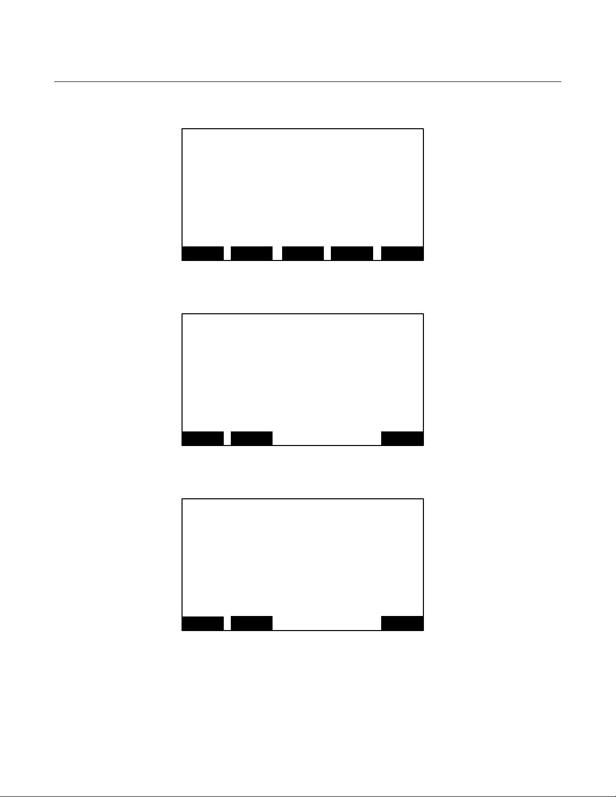
Instruction Manual
760007-A
July 2003
Menu: 45 ANALSIMPLE
Menu: 46 FILTERl1
Menu: 47 LINSET1l1
Basic Controls
Measurement range number:
Range upper limit:
Range and functional control:
Zero gas concentration:
Span gas concentration:
Sample flow:
Ranges with valid calibration:
Calibration status:
HOME
This screen sets the final filtering for
the analyzer primary variable output.
This is in addition to the inherent
filtering in the ana lyzer.
The time delay simply delays the output
by that time, allowing the fastest
responding analyzer systems to be
synchronized with the slowest.
HOME
Allows the setting of linearizer
coefficients, definition of parameter
sets, and filtering and delay.
These all apply to the reporting of the
analyzer primary variable.
HOME
ESCAPE INFO
Filter and Delay Parameters
ZERO
ESCAPE INFO
Primary Variable Parameters
ESCAPE INFO
Model NGA2000 PMD
000.0
000.0
000.0
000.0
000.0
000.0
000.0
000.0
SPAN
7-16 Appendix A. Menu Displays Rosemount Analytical Inc. A Division of Emerson Process Management
Page 61

Model NGA2000 PMD
Menu: 48 LINRANGE0l1
Menu: 49 PLMITSAl1
Menu: 50 CALFACTORS
The linearizer polynomials act over
a certain range, not the same as the
measurement range. The system use s the
linearizer polynomial appropriate for
the measurement range chosen. This is
the polynomial with the next higher
linearizer range than the measurement
range.
Polynomial coefficients may be edited
for custom curves.
HOME
These are settable limits on th e samp le
gas pressure and flow. The force alarms to occur
and also act as end points on the bar graph
display of their variable.
HOME
Range 1 factors…
Range 2 factors…
Range 3 factors…
Range 4 factors…
Zero compensation factor:
Span compensation factor:
HOME
Instruction Manual
760007-A
July 2003
Set Linearity curve
ESCAPE INFO
Pressure and flow Limits
ESCAPE INFO
Calibrati on F actors
000.0
000.0
ESCAPE INFO
Rosemount Analytical Inc. A Division of Emerson Process Management Appendix A. Menu Displays 7-17
Page 62

Instruction Manual
760007-A
July 2003
Menu: 51 R1FACTORS
Menu: 52 RN2FACTORS
Menu: 53 RN3FACTORS
Range 1 Factors
Zero offset:
Span factor:
Full scale range at calibration:
Measurement range number:
Hardware zero offset:
Raw measurement signal:
HOME
Zero offset:
Span factor:
Full scale range at calibration:
Measurement range number:
Hardware zero offset:
Raw measurement signal:
HOME
Zero offset:
Span factor:
Full scale range at calibration:
Measurement range number:
Hardware zero offset:
Raw measurement signal:
HOME
STORE INFO
Range 2 Factors
STORE INFO
Range 3 Factors
STORE INFO
NEXT
NEXT
NEXT
Model NGA2000 PMD
000.0
000.0
000.0
000.0
000.0
000.0
HISTORY
000.0
000.0
000.0
000.0
000.0
000.0
HISTORY
000.0
000.0
000.0
000.0
000.0
000.0
HISTORY
7-18 Appendix A. Menu Displays Rosemount Analytical Inc. A Division of Emerson Process Management
Page 63

Model NGA2000 PMD
A
Menu: 54 RN4FACTORS
Menu: 55 RFACTORSl
Menu: 56 AMHELPINDEX
Zero offset:
Span factor:
Full scale range at calibration:
Measurement range number:
Hardware zero offset:
Raw measurement signal:
HOME
Shows the calibration factors for this range.
Modify the zero factor for zero calibration, and the
span factor for spanning this range. The take effect
as soon as you press the enter key.
With zero gas, the raw reading should be the same as
the zero offset.
Then do a complete recalibration.
HOME
Paramagnetic Oxygen detector
This device uses the paramagnetic nature
of oxygen as a measurement technique.
Other gases are usually diamagnetic and
the detector responds only weakly to them.
Nitrogen oxides are the only
common exceptions.
The analyzer is sensitive to vibratio n
and should be installed with care.
HOME
Range 4 Factors
000.0
000.0
000.0
000.0
000.0
000.0
STORE INFO
ESCAPE INFO
ESCAPE INFO
FIRST
Range Factors
nalyzer Module Help
HISTORY
Instruction Manual
760007-A
July 2003
Rosemount Analytical Inc. A Division of Emerson Process Management Appendix A. Menu Displays 7-19
Page 64

Instruction Manual
A
760007-A
July 2003
Menu: 57 LINRANGE1l1
Menu: 58 CALFACTORSI1
Menu: 59 APARLST2
Model NGA2000 PMD
Linearity coefficients
Edit the polynomial coefficients as
desired. Make sure that the curve upper
limit is correct, this is the limit of
the range that this polynomial will
correct.
The status line selects wh et her the
curve is in use.
HOME
The analyzer uses calibration facto rs fo r each
range. You can adjust them while viewing the rea di n g,
to achieve an accurate calibr a tion. Make sure
the factors are correct for the range you are on.
You will not see a change in the reading if you use
the wrong ones, but you’ll find out when you change
the range! You cannot adjust all ranges at the same
time, you must adjust them one by one.
HOME
Primary Variable Parameters
Control mod e:
Output delay time:
Range 1 upper limit:
Range 2 upper limit:
Range 3 upper limit:
Range 4 upper limit:
Range 1 lower limit:
Range 2 lower limit:
Range 3 lower limit:
HOME
STORE INFO
Calibrati on F actors
ESCAPE INFO
nalyzer Parameter List
ESCAPE INFO
NEXT
BACK
000.0
000.0
000.0
000.0
000.0
000.0
000.0
000.0
000.0
7-20 Appendix A. Menu Displays Rosemount Analytical Inc. A Division of Emerson Process Management
Page 65
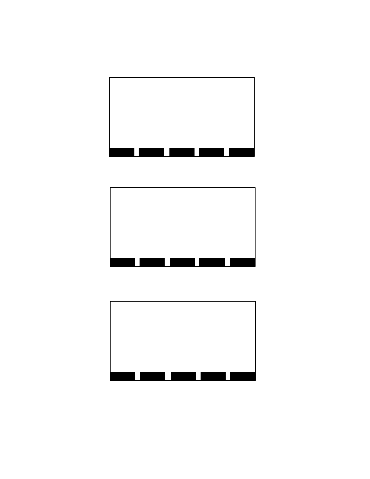
Model NGA2000 PMD
A
A
K
A
Menu: 60 APARLST4
Menu: 61 APARLST5
Menu: 62 APARLST6
Primary Variable Parameters
Range 1 t90 time:
Range 2 t90 time:
Range 3 t90 time:
Range 4 t90 time:
Linearizer on range 1:
Linearizer on range 2:
Linearizer on range 3:
Linearizer on range 4:
HOME
Calibration Parameters
Calibration averaging time:
Calibration failure alarm:
Cal failure error allowed:
Calibration time out:
Ranges zeroed:
Calibrate ranges:
HOME
Calibration Gases
Zero gas – range 1:
Zero gas – range 2:
Zero gas – range 3:
Zero gas – range 4:
Span gas – range 1:
Span gas – range 2:
Span gas – range 3:
Span gas – range 4:
HOME
nalyzer Parameter List
000.0
000.0
000.0
000.0
000.0
000.0
000.0
000.0
ESCAPE INFO
ESCAPE INFO
ESCAPE INFO
NEXT
nalyzer Parameter List
NEXT
nalyzer Parameter List
FIRST
BACK
000.0
000.0
000.0
000.0
000.0
000.0
BAC
000.0
000.0
000.0
000.0
000.0
000.0
000.0
000.0
BACK
Instruction Manual
760007-A
July 2003
Rosemount Analytical Inc. A Division of Emerson Process Management Appendix A. Menu Displays 7-21
Page 66

Instruction Manual
760007-A
July 2003
Menu: 63 DISPLAY
Menu: 64 MPARMS
Menu: 65 MPARMS2
Displayed parameters
First line’s parameter:
Second line’s parameter:
Third line’s parameter:
Fourth line’s parameter:
Displayed concentration digits:
Digits after decimal point:
HOME
Analyzer gas measured:
Measurement range number:
Range change control:
Linearization mode:
Analyzer operational status:
Analyzer alarm state:
Alarm reporting level:
HOME
Response time:
Sample flow:
Sample pressure:
Detector temperature:
HOME
ESCAPE INFO
Current measurement parameters
ESCAPE INFO
Current measurement parameters
ESCAPE INFO
MORE
Model NGA2000 PMD
000.0
000.0
000.0
000.0
000.0
000.0
000.0
000.0
000.0
000.0
000.0
000.0
000.0
000.0
000.0
000.0
000.0
7-22 Appendix A. Menu Displays Rosemount Analytical Inc. A Division of Emerson Process Management
Page 67
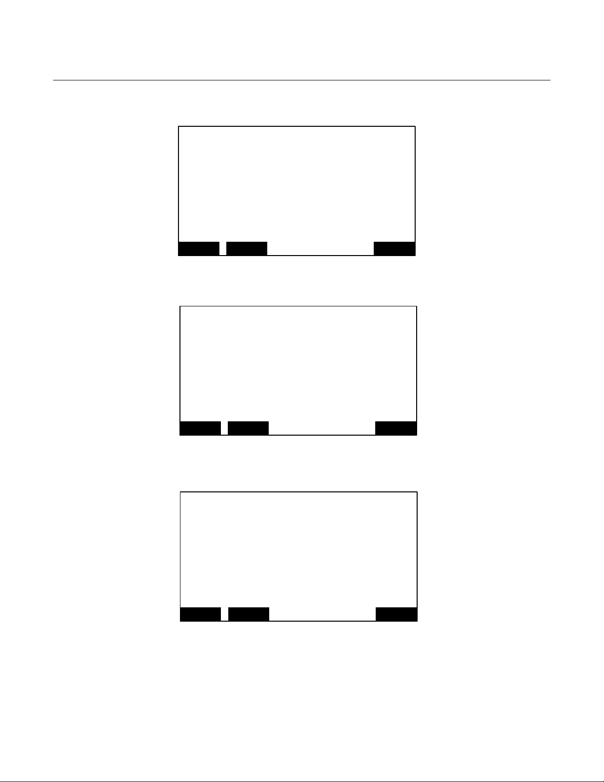
Model NGA2000 PMD
Menu: 66 MPARMSI1
Menu: 67 BAROM_PARMS
Menu: 68 BAROM_PARMI1
Shows the main measurement parameters.
These can be controlled in the various
set up menus.
HOME
Pressure transducer:
Barometric pressure compensation:
Measured pressure:
Transducer offset:
Transducer slope:
Transducer PGA gain:
HOME
Shows whether the optional pressure transducer
is installed or not. Also this screen allows you to
set the transducer. Use the offset at atmospheric
pressure, and pull a vacuum of about 25cm H2O
on the transducer, and use the slope to make it read
correctly.
Choose whether to enable barometric compensation,
and whether to allow the analyzer to emit t h e
pressure value. Only one analyzer at a time in a
HOME
Instruction Manual
760007-A
July 2003
Current measurement parameters help
ESCAPE INFO
Barometric pressure parameters
000.0
000.0
000.0
000.0
000.0
000.0
ESCAPE INFO
Barometric pressure parameters
ESCAPE INFO
Rosemount Analytical Inc. A Division of Emerson Process Management Appendix A. Menu Displays 7-23
Page 68

Instruction Manual
A
760007-A
July 2003
Menu: 69 TLIMITSIAI1
Menu: 70 SW_DIAG
Menu: 71 LISTNOTES
Temperature limits
The limits on the temperature beyond
which the analyzer will send a warning mes sa ge.
The also act as end points to the bar graph display.
The various temperatures are controlled
to values set up in the diagnostic menus.
HOME
Last message:
And:
And:
And:
And:
And:
And:
And:
Edit to reset:
HOME
You can write up to 22 characters in each line.
HOME
ESCAPE INFO
Software diagnostics
ESCAPE INFO
nalyzer module service notes
ESCAPE INFO
Model NGA2000 PMD
000.0
000.0
000.0
000.0
000.0
000.0
000.0
000.0
000.0
000.0
000.0
000.0
000.0
000.0
000.0
000.0
000.0
000.0
7-24 Appendix A. Menu Displays Rosemount Analytical Inc. A Division of Emerson Process Management
Page 69

Model NGA2000 PMD
A
Menu: 72 FLOWLIMITS
Menu: 73 AMPATH
Menu: 74 CALI1
Sample flow upper limit:
Sample flow lower limit:
HOME
Select the function you want in the line below, and not
the path shown.
Function:
Select:
Then:
Then:
Then:
HOME
Use the calibration parameter screen to choos e
to calibrate ranges together or not. If together,
zeroing or spanning will go through each range one by
one. If the change is too great, it will fail, and
send an alarm if warning alarms are enabled.
In this case, disable calibration limit checking and try
again.
If you use non-zero zero gases, or the changes are
HOME
Instruction Manual
760007-A
July 2003
Flow limits
000.0
000.0
ESCAPE INFO
nalyzer Module Help
000.0
000.0
000.0
000.0
000.0
ESCAPE INFO
Calibration info
ESCAPE INFOMORE
Rosemount Analytical Inc. A Division of Emerson Process Management Appendix A. Menu Displays 7-25
Page 70

Instruction Manual
760007-A
July 2003
Menu: 75 LINFUNCT
Menu: 76 POLYSETUP
Menu: 77 MIDPOINT1
Model NGA2000 PMD
Linearization functions
Polynomial set up…
Midpoint correction set up…
Use the polynomial set up to generate a linearizing
polynomial from up to 20 gases. With more than 6 gases
it will produce a fourth order polynomial linearizer.
Use the midpoint correction for a piecewise-linear final
correction, to bring up to three points precisely onto
HOME
Range to be linearized:
Current span gas:
Calculated polynomial order:
Gas values shown as:
Gas concentrations…
HOME
Range 1
Correction:
Point being measured:
Point 1 gas concentration:
Point 2 gas concentration:
Point 3 gas concentration:
Point 1 reading:
Point 2 reading:
Point 3 reading:
Span gas value:
HOME
ESCAPE INFO
Polynomial set up
ESCAPE INFOCALC
Midpoint correction set up
ESCAPE SET NEXT
000.0
000.0
000.0
000.0
000.0
000.0
000.0
000.0
000.0
000.0
000.0
000.0
000.0
INFO
7-26 Appendix A. Menu Displays Rosemount Analytical Inc. A Division of Emerson Process Management
Page 71

Model NGA2000 PMD
A
A
Menu: 78 POLYGAS1
Menu: 79 POLYSETI1
Menu: 80 POLYGAS2
Point 1
Gas value:
Raw readi ng :
Linearized value:
Point 2
Gas value:
Raw readi ng :
Linearized value:
Point to be measured:
HOME
Select the range to linearizer.
Make sure that the span gas value is correct.
Choose whether to define the gas concentrations as
absolute values or as a percent to the span gas.
Use percent if you are diluting the sp a n gas fo r thi s.
Get into the gas concentrations scree ns, and set the
concentration for as many points as you want.
At each point, flow the gas of the correct val u e, and
when the reading is stable, press
The analyzer will store the gas value and the reading
HOME
Point 3
Gas value:
Raw readi ng :
Linearized value:
Point 4
Gas value:
Raw readi ng :
Linearized value:
Point to be measured:
HOME
Gas concentrations
000.0
000.0
000.0
000.0
000.0
000.0
000.0
ESCAPE INFO
ESCAPE INFOMORE
ESCAPE INFO
DAT
Polynomial set up
Gas concentrations
DAT
NEXT
000.0
000.0
000.0
000.0
000.0
000.0
000.0
NEXT
Instruction Manual
760007-A
July 2003
Rosemount Analytical Inc. A Division of Emerson Process Management Appendix A. Menu Displays 7-27
Page 72

Instruction Manual
A
A
A
760007-A
July 2003
Menu: 81 POLYGAS3
Menu: 82 POLYGAS4
Menu: 83 POLYGAS5
Point 5
Gas value:
Raw readi ng :
Linearized value:
Point 6
Gas value:
Raw readi ng :
Linearized value:
Point to be measured:
HOME
Point 7
Gas value:
Raw readi ng :
Linearized value:
Point 8
Gas value:
Raw readi ng :
Linearized value:
Point to be measured:
HOME
Point 9
Gas value:
Raw readi ng :
Linearized value:
Point 10
Gas value:
Raw readi ng :
Linearized value:
Point to be measured:
HOME
ESCAPE INFO
ESCAPE INFO
ESCAPE INFO
Gas concentrations
DAT
Gas concentrations
DAT
Gas concentrations
DAT
Model NGA2000 PMD
000.0
000.0
000.0
000.0
000.0
000.0
000.0
NEXT
000.0
000.0
000.0
000.0
000.0
000.0
000.0
NEXT
000.0
000.0
000.0
000.0
000.0
000.0
000.0
NEXT
7-28 Appendix A. Menu Displays Rosemount Analytical Inc. A Division of Emerson Process Management
Page 73
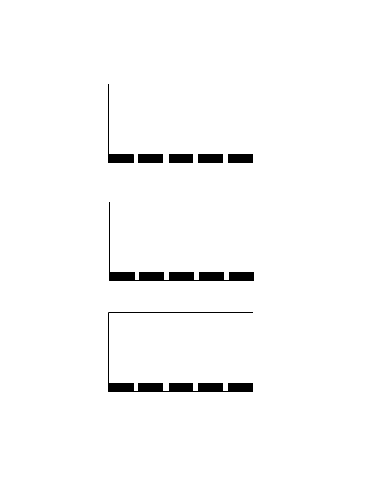
Model NGA2000 PMD
A
A
A
Menu: 84 POLYGAS6
Menu: 85 POLYGAS7
Menu: 86 POLYGAS8
Point 11
Gas value:
Raw readi ng :
Linearized value:
Point 12
Gas value:
Raw readi ng :
Linearized value:
Point to be measured:
HOME
Point 13
Gas value:
Raw readi ng :
Linearized value:
Point 14
Gas value:
Raw readi ng :
Linearized value:
Point to be measured:
HOME
Point 15
Gas value:
Raw readi ng :
Linearized value:
Point 16
Gas value:
Raw readi ng :
Linearized value:
Point to be measured:
HOME
Gas concentrations
000.0
000.0
000.0
000.0
000.0
000.0
000.0
ESCAPE INFO
ESCAPE INFO
ESCAPE INFO
DAT
Gas concentrations
DAT
Gas concentrations
DAT
NEXT
000.0
000.0
000.0
000.0
000.0
000.0
000.0
NEXT
000.0
000.0
000.0
000.0
000.0
000.0
000.0
NEXT
Instruction Manual
760007-A
July 2003
Rosemount Analytical Inc. A Division of Emerson Process Management Appendix A. Menu Displays 7-29
Page 74

Instruction Manual
A
A
760007-A
July 2003
Menu: 87 POLYGAS9
Menu: 88 POLYGAS0
Menu: 89 MIDPOINT2
Gas concentrations
Point 17
Gas value:
Raw readi ng :
Linearized value:
Point 18
Gas value:
Raw readi ng :
Linearized value:
Point to be measured:
HOME
Point 19
Gas value:
Raw readi ng :
Linearized value:
Point 20
Gas value:
Raw readi ng :
Linearized value:
Point to be measured:
HOME
Range 2
Correction:
Point being measured:
Point 1 gas concentration:
Point 2 gas concentration:
Point 3 gas concentration:
Point 1 reading:
Point 2 reading:
Point 3 reading:
Span gas value:
HOME
ESCAPE INFO
Gas concentrations
ESCAPE INFO
Midpoint correction set up
ESCAPE INFO
DAT
DAT
SET
Model NGA2000 PMD
000.0
000.0
000.0
000.0
000.0
000.0
000.0
NEXT
000.0
000.0
000.0
000.0
000.0
000.0
000.0
BACK
000.0
000.0
000.0
000.0
000.0
000.0
000.0
0.000
000.0
NEXT
7-30 Appendix A. Menu Displays Rosemount Analytical Inc. A Division of Emerson Process Management
Page 75

Model NGA2000 PMD
Menu: 90 MIDPOINT3
Menu: 91 MIDPOINT4
Menu: 92 EXP_CAL
Range 3
Correction:
Point being measured:
Point 1 gas concentration:
Point 2 gas concentration:
Point 3 gas concentration:
Point 1 reading:
Point 2 reading:
Point 3 reading:
Span gas value:
HOME
Range 4
Correction:
Point being measured:
Point 1 gas concentration:
Point 2 gas concentration:
Point 3 gas concentration:
Point 1 reading:
Point 2 reading:
Point 3 reading:
Span gas value:
HOME
Measurement range number:
Zero gas concentration:
Span gas concentration:
Sample flow:
Raw measurement signal:
Ranges with valid calibration:
Status:
Result…
HOME
Midpoint correction set up
000.0
000.0
000.0
000.0
000.0
000.0
000.0
000.0
000.0
ESCAPE INFO
Midpoint correction set up
ESCAPE INFO
Zero/span calibration
FACTORS INFO
SET
SET
ZERO
NEXT
000.0
000.0
000.0
000.0
000.0
000.0
000.0
000.0
000.0
BACK
000.0
000.0
000.0
000.0
000.0
000.0
000.0
SPAN
Instruction Manual
760007-A
July 2003
Rosemount Analytical Inc. A Division of Emerson Process Management Appendix A. Menu Displays 7-31
Page 76
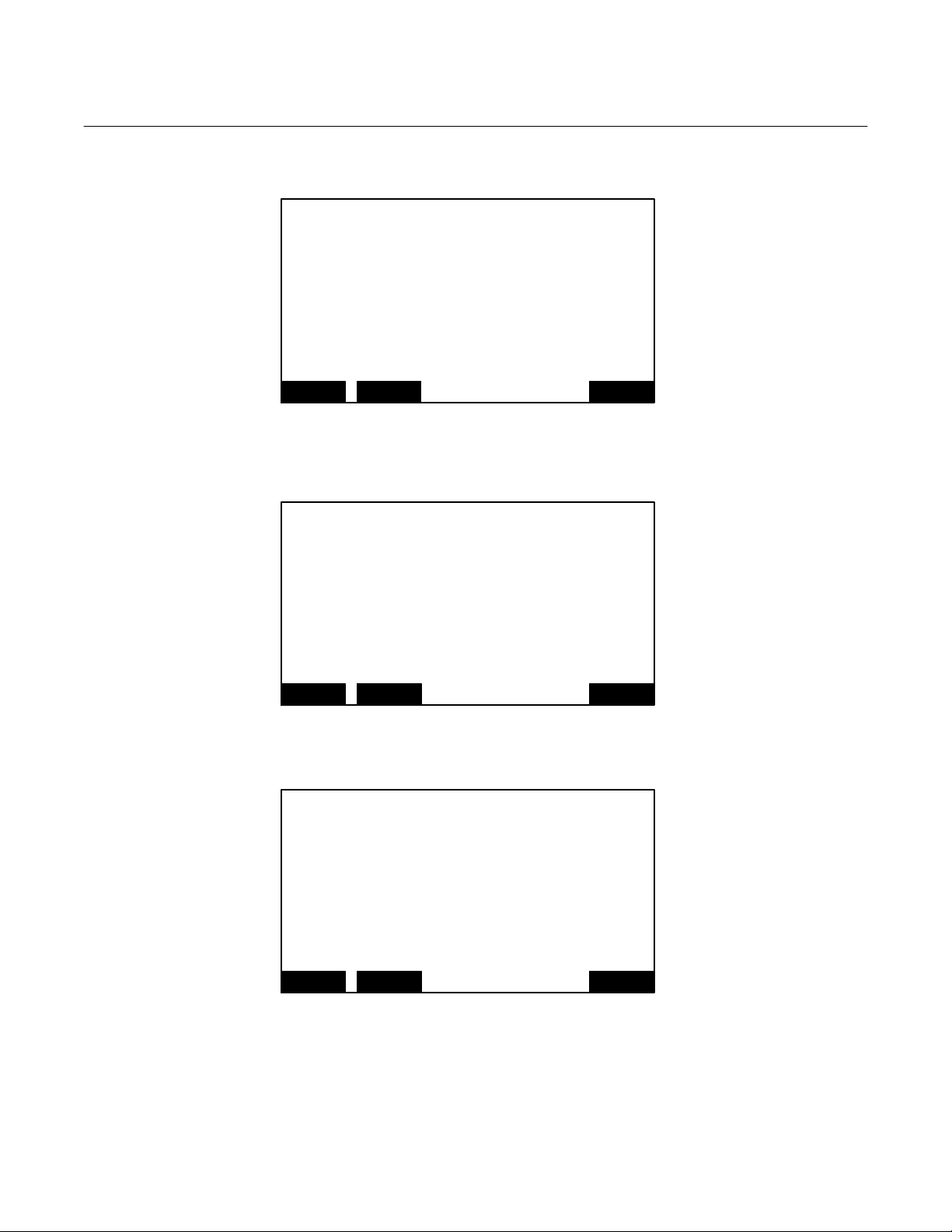
Instruction Manual
760007-A
July 2003
Menu: 93 EXP_CAL_DAT
Menu: 94 EXP_CAL_DATI
Menu: 95 UNITS
Zero/span diagnostic data
Date of last zero:
Error message for last zero:
Error percentage for last zero:
Raw signal at last zero:
Last zero gas would read:
Date of last span:
Error message for last span:
Error percentage for last span:
Raw signal at last span:
HOME
Shows what happened at the last calibration.
The errors are expressed as a percentage of range.
The last zero and span readings are how the analyzer
would read on those gases with the current calibrati on
factors.
HOME
Gas measurement units:
Pressure measurement units:
Temperature measurement units:
Ppm to mg/Nm3 conversion factor:
Lower explosion limit (LEL):
Upper explosion limit (UEL):
HOME
FACTORS INFO
Zero/span diagnostic data
ESCAPE INFO
Units
ESCAPE INFO
Model NGA2000 PMD
000.0
000.0
000.0
000.0
000.0
000.0
000.0
000.0
000.0
000.0
000.0
000.0
000.0
000.0
000.0
7-32 Appendix A. Menu Displays Rosemount Analytical Inc. A Division of Emerson Process Management
Page 77

Model NGA2000 PMD
K
Menu: 96 UNITSI1
Menu: 97 POLYSETI2
Menu: 98 POLYSETI3
Select the units in which you want the values to be
displayed. This does not affect the variabl e contents,
it merely affects how the control module display them.
Note that all analyzer ranges wi ll be set as perce n t or
ppm, you can’t set some as ppm and others as percent.
HOME
When you have entered the desired number of
points, return to the polynomial set up screen, and
press
Polynomial, and stor e it as the coefficients in the
current range’s linearization function.
The order of the polynomial is optimized based onthe
number of data points provided. You need at least 7
points for a fourth order polynomial correction.
You can modify the results with the piecewis e li n e ar
correction also provided in thi s sectio n .
HOME
WARNING: The linearization curve must be monoto nic.
If it is not, the calibration routine will fail and the
analyzer will not calibrate.
Test this by copying the values of the linearization
coefficients into a spreadsheet program and plotting
the result.
The analyzer does test for monotonicity when it spans,
but this test may not catch all possible errors.
Monotonic means that the curve does not roll over
and start going back down as the gas concentration
HOME
Units
ESCAPE INFO
Polynomial set up
ESCAPE INFO
MORE
Polynomial set up
BACK
ESCAPE INFOBAC
Instruction Manual
760007-A
July 2003
Rosemount Analytical Inc. A Division of Emerson Process Management Appendix A. Menu Displays 7-33
Page 78

Instruction Manual
760007-A
July 2003
Menu: 99 RESET
Menu: 100 STORE
Menu: 101 RFHIST1A
Reset
Are you sure?
RESET will erase ALL the configuration and
manufacturing data, including serial numbers and
everything else.
If you are sure, press RESET again.
HOME
Are you sure?
STORE will copy current diagnostic data into the
historical (
currently there.
If you are sure, press STORE again.
HOME
Manufacturer’s settings.
Zero offset:
Span factor:
Stored settings
Zero offset:
Span factor:
HOME
ESCAPE INFORESET
Store historical data
ESCAPE INFO
NEXT INFORSTR STRSTR MN
STORE
Range 1 Factors
Model NGA2000 PMD
000.0
000.0
000.0
000.0
7-34 Appendix A. Menu Displays Rosemount Analytical Inc. A Division of Emerson Process Management
Page 79

Model NGA2000 PMD
Menu: 102 RFACTORSIA
Menu: 103 RFHIST2A
Menu: 104 RFHIST3A
Shows the calibration factors for this range.
Modify the zero factor for zero calibration, and the
span factor for spanning this range. The take effect
as soon as you press the enter key.
With zero gas, the zero factor should be the same as
the raw reading.
RSTR MN restores the manufacturing values.
RSTR ST restore the stored val ues.
HOME
Manufacturer’s settings.
Zero offset:
Span factor:
Stored settings
Zero offset:
Span factor:
HOME
Manufacturer’s settings.
Zero offset:
Span factor:
Stored settings
Zero offset:
Span factor:
HOME
Range Factors
ESCAPE INFO
Range 2 Factors
000.0
000.0
000.0
000.0
NEXT INFO
NEXT INFORSTR STRSTR MN
RSTR MN
Range 3 Factors
RSTR ST
000.0
000.0
000.0
000.0
Instruction Manual
760007-A
July 2003
Rosemount Analytical Inc. A Division of Emerson Process Management Appendix A. Menu Displays 7-35
Page 80

Instruction Manual
K
760007-A
July 2003
Menu: 105 RFHIST4A
Menu: 106 TWEAKI1
Menu: 107 ANALSETI3
Model NGA2000 PMD
Range 4 Factors
Manufacturer’s settings.
Zero offset:
Span factor:
Stored settings
Zero offset:
Span factor:
HOME
This function allow s you to set up to th r ee midpoints
that the analyzer will
It does this with a piece-wise linear alg ori t hm.
This
polynomial linearization.
First disable the correction.
Set the
Then enter the first midpoint gas value, run the gas,
and when stable, press SET.
the actual reading, but the analyzer will
HOME
Then go to the second set point, and repeat.
You can use up to three midpoints.
When you are done, set the correction to
WARNING: make sure that you do not have excessive
corrections. If the correctio n is too odd, the
calibration routine will fail, and you will not be able to
calibrate the anal yzer. In this case, try it again.
You can perform this correction individually for each
range.
HOME
NEXT INFO
Midpoint correction set up
ESCAPE INFO
Midpoint correction set up
ESCAPE INFOBAC
RSTR MN
MORE
RSTR ST
000.0
000.0
000.0
000.0
7-36 Appendix A. Menu Displays Rosemount Analytical Inc. A Division of Emerson Process Management
Page 81

Model NGA2000 PMD
Menu: 108 ACALSETI1A
Menu: 109 INIT
Menu: 110 SWDIAGI1
Disable the limits to reco v er from calibration failure
Calibration averaging time sets the time used by the
analyzer to average its reading. Longer times will give
a better calibration.
Calibration failure alarm will issue a WARNIN G if the
analyzer has to change calibration by more than the
Cal failure error, if warning alarms are enabled.
Calibration time out sets how long the analyzer will wait
for the signal to stabilize before issuing a WARNING.
You can zero or span the ranges all at once or not.
HOME
Are you sure?
INIT will erase ALL the configuration data, including
manufacturing data, serial numbers etc.
If you are sure, press INIT again.
HOME
Shows the first detected software error since the
variable on the bottom line was r eset.
Please report any errors to your service
representative. They may mean nothing.
The analyzer has a lot of error recovery code.
Errors may therefore correct themselves.
HOME
Calibration Parameters
ESCAPE INFO
Re-initialize the analyzer
ESCAPE INFO
Software Diagnostics
ESCAPE INFO
INIT
Instruction Manual
760007-A
July 2003
Rosemount Analytical Inc. A Division of Emerson Process Management Appendix A. Menu Displays 7-37
Page 82
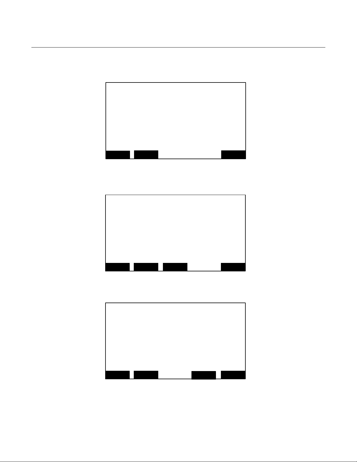
Instruction Manual
A
A
760007-A
July 2003
Menu: 111 STOREDPVA
Menu: 112 ZERO_NOW
Menu: 113 SPAN_NOW
Model NGA2000 PMD
Trend display control
The analyzer stores 24 hours of 15 minute averages.
These values are only accessible via a PC.
Use the variables DATA_INDEX and D ATA_POINT
to access them.
HOME
Are you sure?
You must have zero gas flowing through the analyzer.
This control does NOT control any auto-calibration
module bound to this analyzer!
If you are sure, press ZERO again now.
Press the left arrow key when you are done.
Calibration status: 000.0
HOME
Are you sure?
You must have span gas flowing through the analyzer.
This control does NOT control any auto-calibration
module bound to this analyzer!
If you are sure, press SPAN again now.
Press the left arrow key when you are done.
Calibration status: 000.0
HOME
ESCAPE INFO
nalyzer zero
ESCAPE INFO
ESCAPE INFO
ZERO
nalyzer span
SPAN
7-38 Appendix A. Menu Displays Rosemount Analytical Inc. A Division of Emerson Process Management
Page 83

Model NGA2000 PMD
Menu: 114 CALFAIL
Menu: 115 ABOUT
Menu: 116 ABOUT1
Check that you are flowing the correct gas, and the
gas concentration is what it is supposed to be.
Make sure that the reading is stable before staring.
If you have enabled or disabled the linear iz er, you
may have made it hard for the analyzer to calibrate.
If so, go to the calibration parameters screen under
Expert controls and set up, under Analyzer set up,
and disable the limits checki ng. Recali brate, and then
enable the limits checking aga in.
If all else fails, manually adjust the calibration factors
HOME
(C) Copyright Fisher-Rosemount Analytical Inc., 2000
Manufactured by:
Rosemount Analytical Inc.
4125 East La Palma Avenue
Anaheim, CA 92807-1802 /USA
Tel: (714) 986-7600
FAX: (714) 577-8739
Measure
-- Analyzer Module Version Information --
Serial number:
Manufacturing date:
Hardware revision:
Software revision:
Revision date:
Revision time:
Measure
If it won’t calibrate…
ESCAPE INFO
Back…
Back…
More…
000.0
000.0
000.0
000.0
000.0
000.0
Instruction Manual
760007-A
July 2003
Rosemount Analytical Inc. A Division of Emerson Process Management Appendix A. Menu Displays 7-39
Page 84

Instruction Manual
A
760007-A
July 2003
Menu: 117 ALARM1
Menu: 118 MANDATA
Menu: 119 AUTORANGE
Concentration Alarm Setup
Alarm generation is:
Level for Low-Low alarm:
Level for Low alarm:
Level for High alarm:
Level for High-High alarm:
Alarm delay:
Low-Low alarm:
Low alarm:
High alarm:
HOME
Serial number:
Set manufacturing date!
Actual date:
Measure Back…
Actual switch levels…
Switch level hysteresis:
Usage of range -1:
Usage of range -2:
Usage of range -3:
Usage of range -4:
Automatic range change control:
Absolute, range upper limit:
Measure
ESCAPE
-- Manufacturing data… --
-- Autom a tic Range Control --
CKN
Back…
Model NGA2000 PMD
000.0
000.0
000.0
000.0
000.0
000.0
000.0
000.0
000.0
000.0
000.0
000.0
000.0
000.0
000.0
000.0
000.0
000.0
7-40 Appendix A. Menu Displays Rosemount Analytical Inc. A Division of Emerson Process Management
Page 85

Model NGA2000 PMD, NDIR
VAISALA BAROMETRIC PRESSURE TRANSDUCER
Addendum
748461-B
April 2003
This addendum serves as an amendment to
the Model NGA 2000 PMD and NDIR instruction manuals. The following information
should be considered part of the manual, if
your instrument has a Vaisala Barometric
Pressure Transducer installed in it, or if you
are retrofitting a PMD or NDIR with a Vaisala
transducer kit.
The Vaisala PTB100 series Analog Barometer
is a N.I.S.T. traceable precision silicon capacitive atmospheric pressure transducer. The
sensor delivers an analog voltage output that
is inversely proportional to its inlet pressure. It
has an operational ambient pressure range of
800 to 1060 hPa.
The original PMD and NDIR instruments were
designed for use with a resistance bridge type
of pressure transducer requiring an external
gain amplifier with an offset trim The Vaisala
transducer contains an integral gain amplifier
that is scaled for a 0 to +5 Vdc output. The
661380 “Interface Board” contains the circuitry to convert the Vaisala single ended 0 to
+5 V dc output into the referenced bridge 0 to
+0.625 V dc output configuration that is required by the Analyzer module’s Computer
Analysis Board. The Vaisala transducer kit is
backward compatible with the original Rosemount pressure transducer.
Vaisala Interface Board Circuit Function:
The Vaisala Interface Circuit board adapts the
single ended analog output of the Vaisala
sensor into a Precision Voltage referenced,
balanced bridge (at 1 atmosphere) input configuration. A “Bridge Balance” pot on the
Vaisala Interface Circuit board provides the
fine trim “Bridge Balancing” calibration adjustment that is required to set up each indi-
vidual transducer at a known ambient air
pressure. Test points are provided on the circuit board for this adjustment.
The Vaisala transducer output range is 0 to
+5 Vdc.
The Vaisala analog output voltage is inverted
and fed into a balanced summing node that is
referenced by a precision regulator. The
summing node voltage is 0.000 Vdc at 1013
hPa (1 atmosphere ambient air pressure). The
summing node voltage is then buffered, inverted, and gain reduced by a factor of 8 to
produce the Pressure Compensation Output
voltage at J12-1 for the Computer Analysis
board.
Low noise, Low input current offset Op-Amps,
and common substrate resistors are used to
reduce gain tracking errors and null thermal
coefficient effects.
1-1 INSTALLATION & RETROFIT
INSTRUCTIONS
1. Remove the original Rosemount transducer circuit board assembly, located on
the motherboard at J12 and J13 (if present).
2. Install the transducer with the pressure
inlet facing the rear of the instrument using the mounting studs provided on lefthand side of the detector housing.
3. Install the Interface board into it’s mating
sockets (J12 and J13) on the motherboard.
4. Connect the 4-pin cable (P1) from the interface board (noting pin polarity) to the
Vaisala Pressure Transducer.
http://www.processanalytic.com
Page 86

Addendum
748461-B
April 2003
5. Connect the instrument sample inlet tubing to the Vaisala Pressure Inlet port.
Model NGA2000 PMD, NDIR
Barometric Pressure menu reads the correct
ambient air pressure.
6. Enable the Barometric Pressure Compensation and the Use Local Reading options via the Expert Controls – Analyzer
Module Diagnostics – Barometric Pressure Compensation menus of the instrument. The instrument will automatically
detect and report the ‘Presence’ of the
Pressure Compensation Option.
1-2 ADJUSTMENT PROCEDURE
Circuit adjustment can be made using Barometric Pressure menu display, or an external
Digital voltmeter.
Display Method
With no sample inlet lines connected and the
instrument exhaust ported to atmosphere, adjust R1 on the 661380 Interface board until
the Barometric Pressure reading on the
DMM Method
Connect the DMM (+) to TP1 on the 661380
Interface board, (-) to TP2. Set the DMM to
measure mVDC. With no sample inlet lines
connected and the instrument exhaust ported
to atmosphere, adjust R1 on the Interface
board until the DMM reads 0.000 Vdc ± 0.001
V. The instrument is now calibrated at 1
ATM.
1-3 HIGH ALTITUDE VERSION OPTION
For applications where the instrument is to be
used above 5400 Feet (MSL) an alternate
transducer option is available from the factory.
This version consists of a Vaisala model
PTB100B transducer (900-1100 hPa range).
Please contact the factory if you require this
option.
2 of 2
Addendum – Vaisala Transducer Rosemount Analytical Inc. A Division of Emerson Process Management
Page 87

WARRANTY
Goods and part(s) (excluding consumables) manufactured by Seller are warranted to be free from
defects in workmanship and material under normal use and service for a period of twelve (12)
months from the date of shipment by Seller. Consumables, glass electrodes, membranes, liquid
junctions, electrolyte, o-rings, etc., are warranted to be free from defects in workmanship and
material under normal use and service for a period of ninety (90) days from date of shipment by
Seller. Goods, part(s) and consumables proven by Seller to be defective in workmanship and/or
material shall be replaced or repaired, free of charge, F.O.B. Seller's factory provided that the
goods, part(s) or consumables are returned to Seller's designated factory, transportation charges
prepaid, within the twelve (12) month period of warranty in the case of goods and part(s), and in
the case of consumables, within the ninety (90) day period of warranty. This warranty shall be in
effect for replacement or repaired goods, part(s) and the remaining portion of the ninety (90) day
warranty in the case of consumables. A defect in goods, part(s) and consumables of the
commercial unit shall not operate to condemn such commercial unit when such goods, part(s)
and consumables are capable of being renewed, repaired or replaced.
The Seller shall not be liable to the Buyer, or to any other person, for the loss or damage directly
or indirectly, arising from the use of the equipment or goods, from breach of any warranty, or from
any other cause. All other warranties, expressed or implied are hereby excluded.
IN CONSIDERATION OF THE HEREIN STATED PURCHASE PRICE OF THE GOODS,
SELLER GRANTS ONLY THE ABOVE STATED EXPRESS WARRANTY. NO OTHER
WARRANTIES ARE GRANTED INCLUDING, BUT NOT LIMITED TO, EXPRESS AND IMPLIED
WARRANTIES OR MERCHANTABILITY AND FITNESS FOR A PARTICULAR PURPOSE.
Limitations of Remedy.
DELAY IN PERFORMANCE. THE SOLE AND EXCLUSIVE REMEDY FOR BREACH OF
WARRANTY SHALL BE LIMITED TO REPAIR OR REPLACEMENT UNDER THE STANDARD
WARRANTY CLAUSE. IN NO CASE, REGARDLESS OF THE FORM OF THE CAUSE OF
ACTION, SHALL SELLER'S LIABILITY EXCEED THE PRICE TO BUYER OF THE SPECIFIC
GOODS MANUFACTURED BY SELLER GIVING RISE TO THE CAUSE OF ACTION. BUYER
AGREES THAT IN NO EVENT SHALL SELLER'S LIABILITY EXTEND TO INCLUDE
INCIDENTAL OR CONSEQUENTIAL DAMAGES. CONSEQUENTIAL DAMAGES SHALL
INCLUDE, BUT ARE NOT LIMITED TO, LOSS OF ANTICIPATED PROFITS, LOSS OF USE,
LOSS OF REVENUE, COST OF CAPITAL AND DAMAGE OR LOSS OF OTHER PROPERTY
OR EQUIPMENT. IN NO EVENT SHALL SELLER BE OBLIGATED TO INDEMNIFY BUYER IN
ANY MANNER NOR SHALL SELLER BE LIABLE FOR PROPERTY DAMAGE AND/OR THIRD
PARTY CLAIMS COVERED BY UMBRELLA INSURANCE AND/OR INDEMNITY COVERAGE
PROVIDED TO BUYER, ITS ASSIGNS, AND EACH SUCCESSOR INTEREST TO THE GOODS
PROVIDED HEREUNDER.
Force Majeure.
Seller's direct control.
Seller shall not be liable for failure to perform due to labor strikes or acts beyond
SELLER SHALL NOT BE LIABLE FOR DAMAGES CAUSED BY
Page 88

Instruction Manual
A
760007-A
July 2003
Model NGA2000 PMD
EMERSON PROCESS MAN
ROSEMOUNT ANALYTICAL INC.
Process Analytic Division
1201 N. Main St.
Orrville, OH 44667-0901
T (330) 682-9010
F (330) 684-4434
E gas.csc@emersonprocess.com
ASIA - PACIFIC
Fisher-Rosemount
Singapore Private Ltd.
1 Pandan Crescent
Singapore 128461
Republic of Singapore
T 65-777-8211
F 65-777-0947
http://www.processanalytic.com
© Rosemount Analytical Inc. 2003
GEMENT
EUROPEAN TECHNOLOGY CENTER
Fisher-Rosemount GmbH & Co.
Industriestrasse 1
63594 Hasselroth
Germany
T 49-6055-884 0
F 49-6055-884209
EUROPE, MIDDLE EAST, AFRICA
Fisher-Rosemount Ltd.
Heath Place
Bognor Regis
West Sussex PO22 9SH
England
T 44-1243-863121
F 44-1243-845354
LATIN AMERICA
Fisher - Rosemount
Av. das Americas
3333 sala 1004
Rio de Janeiro, RJ
Brazil 22631-003
T 55-21-2431-1882
 Loading...