

Page 1

NGA 2000
Software Manual
CLD - Analyzer Module
Chemiluminescence - Measurement
(combined with NGA 2000 - Platform / MLT - Analyzer)
CLD Software V e rsion 2.3
(Platform / MLT Software Version 3.1.X)
1. Edition 04/98
Catalog No.: 90 003 749
90003749(1) [NGA-e (CLD-Software 2.3 / MLT-Software 3.1.X)] 04/98
Managing The Process Better
Page 2
This Operation Manual includes information about the operation of the instrument.
Information about the additional indications and notes regarding maintenance, troubleshooting and repair
are found in the accompanying Maintenance & Operation Manual.
T roubleshooting, component replacement and internal adjustments must be made by qualified
service personnel only.
Fisher-Rosemount GmbH & Co does not take responsibility for an y omissions or errors in this manual.
Any liability for direct or indirect damages, which might occur in connection with the deliv ery or the use of
this manual, is expressly e xcluded to the extend permitted by applicable law.
This instrument has left the works in good order according to safety regulations.
T o maintain this operating condition, the user must strictly follow the instructions and consider the warnings
in this manual or provided on the instrument.
Misprints and alterations reserved
©
1998 by FISHER-ROSEMOUNT GmbH & Co. (PAD)
1. Edition: 04/98
Read this operation manual carefully before attempting to operate the analyzer !
For expedient handling of reports of defects , please include the model and serial number which
can be read on the instrument identity plate.
Fisher - Rosemount GmbH & Co.
Industriestrasse 1
D - 63594 Hasselroth • Germany
Phone + 49 (6055) 884-0
Telefax + 49 (6055) 884-209
Internet: http://www.processanalytic.com
90003749(1) [NGA-e (CLD-Software 2.3 / MLT-Software 3.1.X)] 04/98
Page 3

Contents
1 Introduction 1 - 1
2 Structure of Menus 2 - 1
3 Display and Keyboard 3 - 1
3.1 Starting and Initializing...................................................................................3 - 1
3.2 Display and Function...................................................................................... 3 - 1
3.3 Operating Keys ..............................................................................................3 - 2
3.4 Lines...............................................................................................................3 - 2
3.5 Important Functions of the Softkeys...............................................................3 - 3
3.6 Entering/Changing of Variables......................................................................3 - 4
3.7 The STATUS Key...........................................................................................3 - 5
4 Basic Controls 4 - 1
4.1 Measurement 4 - 3
4.1.1 Multi Component Display: Change of Channel ..............................................4 - 3
4.1.2 Multi Component Display: Sequence Setup...................................................4 - 5
4.1.3 Range Setting ................................................................................................4 - 7
4.1.4 Range and Functional Control .......................................................................4 -11
4.1.5 Enable/Disable Ozonator Power....................................................................4 -15
4.1.6 Measurement Mode: NO ↔↔ NOx....................................................................4 -19
4.2 Calibration 4 -21
4.2.1 Zeroing...........................................................................................................4 -21
4.2.2 Spanning........................................................................................................ 4 -25
4.2.3 If It Won't Calibrate.........................................................................................4 -29
90003749(1) [NGA-e (Software CLD 2.3/MLT 3.1.X)] 04/98
NGA 2000
I
Page 4

5 Expert Controls and Set up 5 - 1
5.1 Analyzer Module Set up 5 - 3
5.1.1 Calibration/Calibration Gas List......................................................................5 - 4
5.1.2 Calibration Parameters...................................................................................5 - 9
5.1.3 Gas Measurement Parameters ......................................................................5 -11
5.1.4 Linearization Parameters................................................................................5 -12
5.1.5 Response Time/Delay Parameters.................................................................5 -14
5.1.6 Range Settings...............................................................................................5 -16
5.1.7 Units ...............................................................................................................5 -17
5.1.8 Linearization Functions...................................................................................5 -18
5.1.9 Analyzer Parameter List .................................................................................5 -23
5.1.10 Physical Measurement Parameters................................................................5 -26
5.1.11 Displayed Parameters ....................................................................................5 -28
5.2 Auxiliary Module Controls 5 -29
5.2.1 Local SIO Configuration Sections...................................................................5 -30
5.2.2 Set-up DIO Module(s).....................................................................................5 -39
5.3 Auxiliary Module Set up 5 -45
5.4 System Set up 5 -47
5.4.1 Front Panel Control ........................................................................................5 -48
5.4.2 Display Resolution..........................................................................................5 -50
5.4.3 Auxiliary Lines.................................................................................................5 -51
5.5 Expert Analyzer Controls 5 -53
5.5.1 Range Settings...............................................................................................5 -55
5.5.2 Zero/Span Calibration.....................................................................................5 -56
5.5.3 Physical Measurements..................................................................................5 -60
II
NGA 2000
90003749(1) [NGA-e (Software CLD 2.3/MLT 3.1.X)] 04/98
Page 5

6 Technical Level Configuration 6 - 1
6.1 System Set up 6 - 3
6.1.1 Main Display Configuration ............................................................................6 - 4
6.1.2 Front Panel Control........................................................................................6 - 9
6.1.3 Date and Time Set up....................................................................................6 -11
6.1.4 Module Binding ..............................................................................................6 -12
6.1.5 System Reset.................................................................................................6 -14
6.1.6 Security Codes...............................................................................................6 -15
6.2 Service Menus 6 -17
6.2.1 Control Module Data......................................................................................6 -18
6.2.2 Analyzer Module Data.................................................................................... 6 -19
6.2.3 Control Module History...................................................................................6 -21
6.2.4 Analyzer Module History ................................................................................6 -23
6.3 Diagnostic Menus 6 -25
6.3.1 Control Module Diagnostics ...........................................................................6 -26
6.3.2 Analyzer Module Diagnostics.........................................................................6 -27
6.3.2.1 Power Supply Voltages ...................................................................6 -28
6.3.2.2 Primary Variable Parameters ..........................................................6 -29
6.3.2.3 Physical Measurements ..................................................................6 -33
6.3.2.4 Temperature Control.......................................................................6 -35
6.3.2.5 Flow Control Parameters.................................................................6 -36
6.3.2.6 Miscellaneous Control Parameters..................................................6 -38
6.3.2.7 Trend Display Control......................................................................6 -39
6.3.2.8 Software Diagnostics.......................................................................6 -41
6.3.2.9 Analyzer Start up............................................................................. 6 -42
6.3.2.10 NOx Converter Efficiency.................................................................6 -43
6.4 Other Module Diagnostic Menus 6 -44
6.5 Listing of all Modules 6 -45
Supplement: System Calibration
90003749(1) [NGA-e (Software CLD 2.3/MLT 3.1.X)] 04/98
NGA 2000
III
Page 6

IV
NGA 2000
90003749(1) [NGA-e (Software CLD 2.3/MLT 3.1.X)] 04/98
Page 7
1 Introduction
This software manual describes step by step how to operate successfully with the ½ 19"
and 19" MLT analyzer module and analyzer of the NGA 2000 Series from .
Chapter two shows the structure of the software menus. Chapter three describes the
display and the keyboard of the analyzer. Chapter four describes the basic controls with
detailed illustrations. So you can easily compare the actual display of the analyzer module
with the illustrations of the manual.
Chapter five describes the expert controls and chapter six describes the technical level
configuration. The layout of both chapters is not as detailed as in chapter four. Normally,
the way to a certain software menu is described with the software catchwords, you have to
press to reach this menu. You will find the illustration of the corresponding LCD screen at
the end of the catchword listing. After that you can read the meaning of the functions and
variables of each expert or technical level menu.
Some contents of the expert controls are not important for every customer. It depends on
the configuration of your NGA 2000 system, relative to the following components:
♦ Control Module CM
♦ Analyzer Module AM
♦ Input/Output Modules I/O's (SIO, DIO)
You can distinguish the following system units and SIO/DIO configurations:
System Unit SIO/DIO-Configuration Corresponding Chapter
1
CLD analyzer module (AM):
• without front panel i.e.
⇒ Local I/O's are not existing
∗ ⁄⁄
without control unit
• can be combined with a
platform or an MLT analyzer
Platform (CM software):
• Control unit with front panel
• without measurement
channels
⇒ 1 SIO and up to 4 DIO's
can be installed in the
platform
⇒ SIO and DIO can be
∗ chapter 5.2
p. 29 to 44
configured for all channels
combined with the platform
MLT analyzer
(CM and MLT AM software):
• Analyzer with front panel
• CM and AM software in the
same analyzer,
i.e. all functions of the control
unit and of the AM are united
⇒ 1 SIO and 1 DIO can be
installed in the MLT
analyzer
⇒ SIO and DIO can be con-
figured for all channels
combined with the MLT
analyzer
∗ chapter 5.2
p. 29 to 44
in the same implement
1
The configuration of other analyzer modules like MLT modules is described in their own manuals !
90003749(1) [NGA-e (Software CLD 2.3/MLT 3.1.X)] 04/98
NGA 2000
1 - 1
Page 8
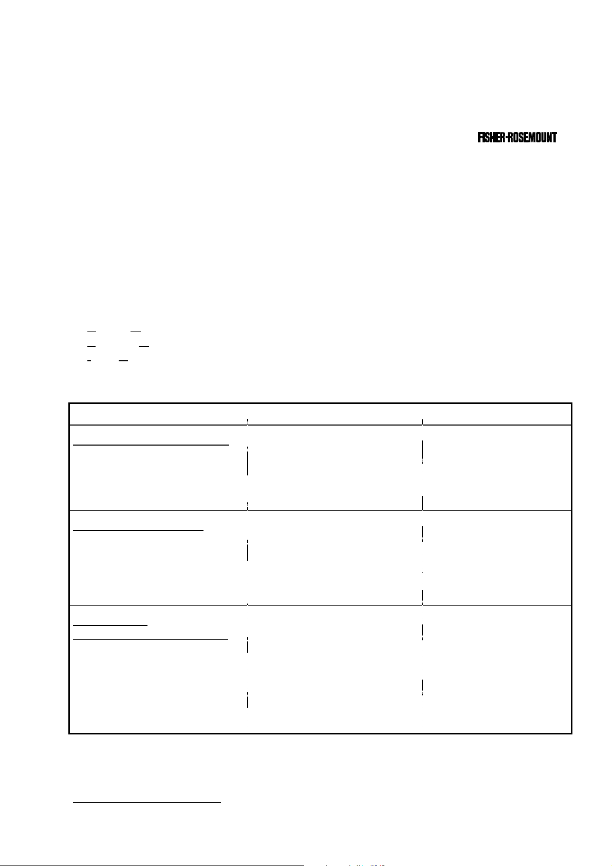
The following illustrations shall make plain the connection between the hardware configuration and the software setup of the modules:
NGA 2000 System via Platform
(see 5.1.17)
(see 5.1.18)
(other manuals)
(other manuals)
(other manuals)
Local
I/O's
SIO
DIO
Analyzer
Modules (AM's)
Control
Module (CM)
MLT
CLD
FID
Platform
PMD
NGA 2000 System via MLT Analyzer
Auxiliary
Modules
SIO
DIO
Other I/O´s
(see 5.2.1)
(see 5.2.2)
(other manuals)
Local
I/O's
(see 5.1/5.5)
SIO
DIO
Analyzer
Modules (AM's)
CLD
MLT
FID(other manuals)
PMD(other manuals)
Control
Modul (CM)
MLT Analyzer
Auxiliary
Modules
SIO
DIO
(see 5.2.1)
(see 5.2.2)
1 - 2
NGA 2000
90003749(1) [NGA-e (Software CLD 2.3/MLT 3.1.X)] 04/98
Page 9
Notes:
*
In the menu structure shown above, you will find the most important ramifications of the MLT software 3.1.X for the
MLT platform and analyzer versions. The menu points related to the CLD analyzer module are marked with
They belong to the CLD software revision number 2.3.
*
At each menu point of the "Expert controls" and "Technical level" you can find which functionality will be set up:
odule), CM (
odule), I/O (
utput Module).
*
Menu lines ending with three points (...) are followed by submenus with further functions and set-ups.
-
-
-
-
-
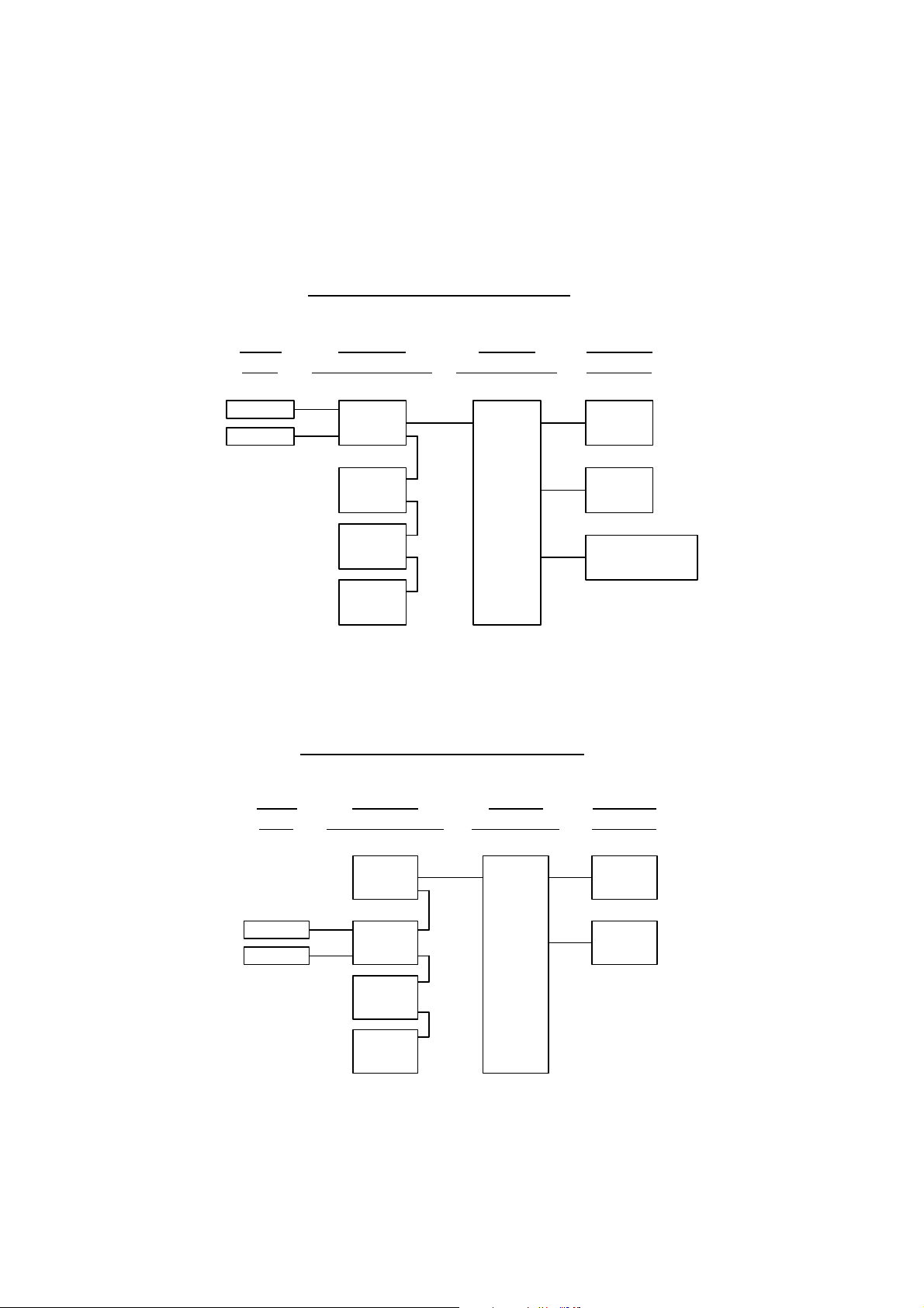
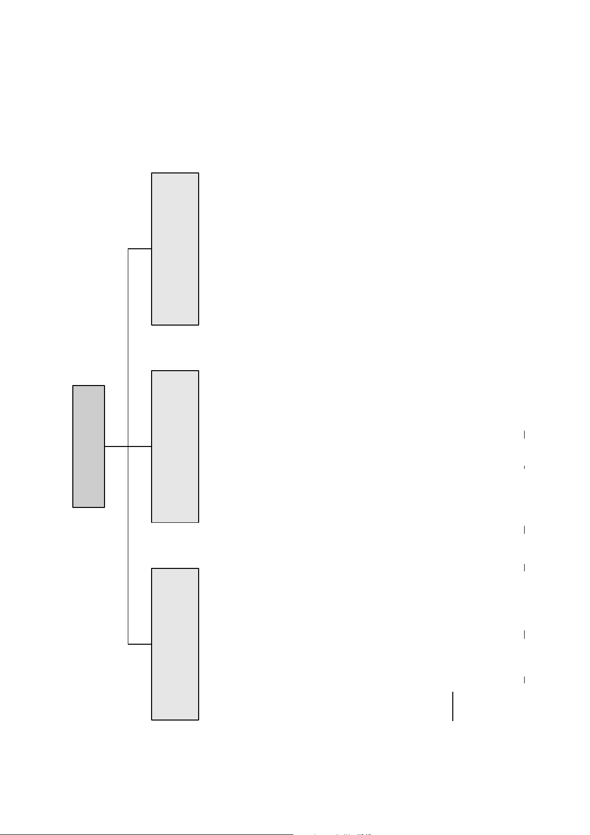
Technical level
configuration...
2 Structure of Menus
"AM".
Main Menu
(CM)
- System set up...
and set up...
Expert controls
controls...
- Expert analyzer
(AM, CM, I/O's:
SIO, DIO and other I/O's)
- Service menus...
(AM)
controls...
- Auxiliary module
(AM, CM, I/O's:
SIO, DIO and other I/O's)
- Diagnostic menus...
(I/O's: SIO, DIO)
(CM)
- System set up...
diagnostic menus...
(Other I/O's)
- Other module
(AM)
- Analyzer module set up...
(AM, CM, I/O's:
SIO, DIO and other I/O's)
- Listing of all modules...
(Other I/O's)
- Auxiliary module set up...
(CM)
- System calibration...
Input-/O
Control M
Basic controls... (AM)
90003749(1) [NGA-e (Software CLD 2.3/MLT 3.1.X)] 04/98
Range set-up
Range and
functional control
Ozonator power
enable/disable
NGA 2000
Measurement mode
selection: NO/NOx-Zeroing...
Spanning...
AM (Analyzer M
2 - 1
Page 10

2 - 2
NGA 2000
90003749(1) [NGA-e (Software CLD 2.3/MLT 3.1.X] 04/98
Page 11
3 Display and Keyboard
3.1 Starting and Initializing
After switching on the CLD analyzer module (in a platform or part of a NGA network), the
initialization procedure will be performed. A self control of the analyzer modules or the
analyzer(s) is running. You can see a sequence of several displays. They show the status
of initialization, revision notes of the MLT software and the tag. At the end
of this procedure you can see the single component display of channel one. It is the origin
to all the other channels, menus and submenus.
The instructions of the basic controls (chapter four) are all beginning with the single component display. The actual display might differ from the shown one because the customer
can configure it according to his requirements.
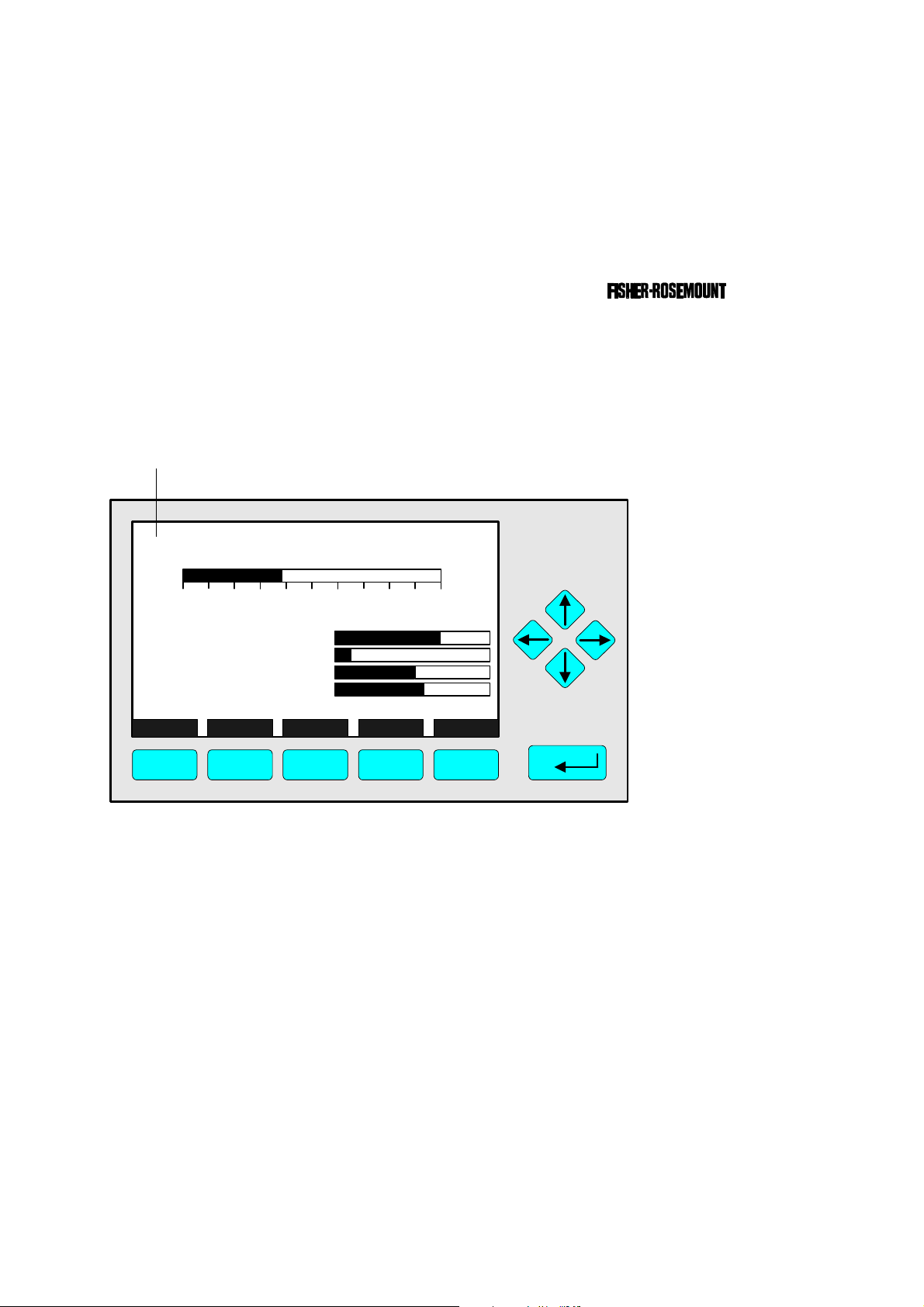
TAG
here e.g.: CLD Analyzer Module
CLD
95.00 ppm NOx
0 250
Sample press.:
Detector temperature:
Block temperature:
Converter temp.:
DISPLAY STATUS MENU NEXT INFO
F1 F2 F3 F4 F5
Typical starting menu after switching on
Range: 4
340 hPa
0.5 C
51.5 C
360 C
3.2 Display and Function
The LCD-screen shows all measurement values of the analyzer and all customer instructions. You can operate with five function keys, four arrow keys (cursors) and the enter key.
The function of each key depends on:
♦ the type of analyzer/analyzer module used
♦ the optional auxiliary modules (e.g. I/O boards) used
♦ the individual menu displayed
In case of power failure all customer specific module parameters are saved by a batterypowered buffer.
90003749(1) [NGA-e (Software CLD 2.3/MLT 3.1.X)] 04/98
NGA 2000
3 - 1
Page 12
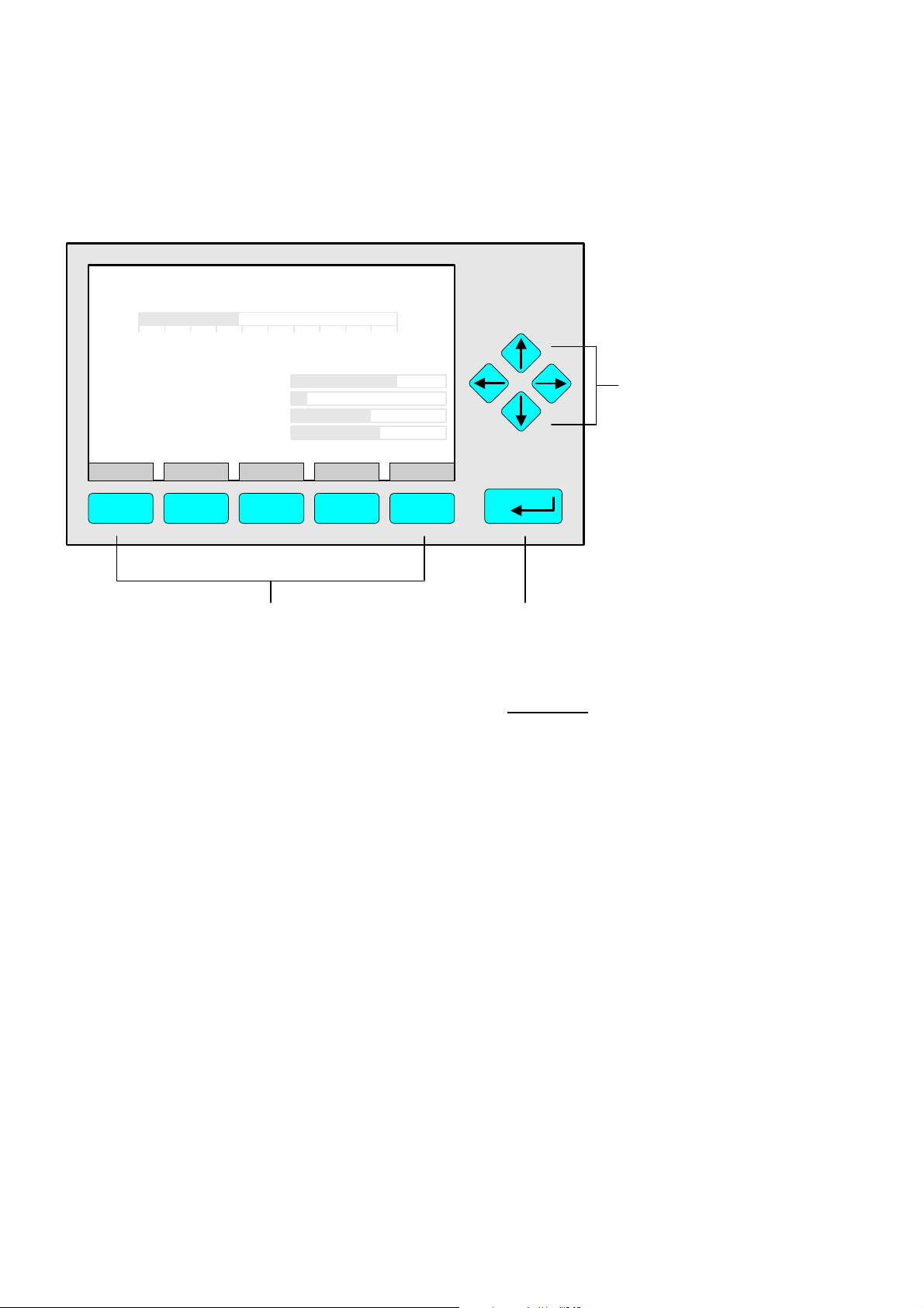
3.3 Operating Keys
CLD
95.00 ppm NOx
0 250
Sample press.:
Detector temperature:
Block temperature:
Converter temp.:
DISPLAY STATUS MENU NEXT INFO
F1 F2 F3 F4 F5
Range: 4
340 hPa
0.5 C
51.5 C
360 C
Function Keys:
♦ Keys without defined functions
♦ The current function depends on
the menu selected
♦ The softkey legend is shown on
the display above the key
3.4 Lines
Cursor keys:
↑↑ -key / ↓↓ -key:
♦ Line up / line down
within the same menu
♦ Alteration of numbers,
variables or digits
←← -key/ →→ -key:
♦ Moving back/forwards
between the pages of
a menu
♦ Selection of digits
Enter Key:
♦ To confirm a previously entered value
(variable)
♦ To start a selected function
(Alternative: →→ -key)
♦ To go into a menu (via menu line)
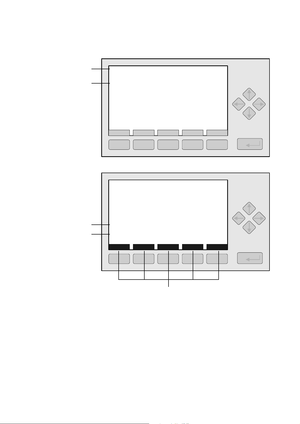
Lines can be selected by the ↓↓ -key or the ↑↑ -key. The selected line is displayed white on
black. You have four different types of lines in the menu:
Menu line...
♦ Line ending with three dots.
♦ You will go to a submenu by pressing the ENTER key or the →→ -key in such a line.
Function line !
♦ Line ending with an exclamation-mark.
♦ You will start a function (e.g. NO/NO
-toggle) by pressing the ENTER key or
x
the →→ -key in such a line.
Line of variables:
♦ Line ending with a colon.
♦ Display of module parameters (variables).
♦ Some parameters can be changed (e.g. range number), some parameters display only
a status (e.g. calibration status) and cannot be changed.
Text line
♦ Line without any punctuation marks.
♦ Only display of informations (e.g. analyzer module tag).
3 - 2
NGA 2000
90003749(1) [NGA-e (Software CLD 2.3/MLT 3.1.X)] 04/98
Page 13
3 Display and Keyboard
Text Line
Line of Variables
Function Line
Menu Line
CLD
Basic Controls
Measurement range number: 4
Range upper limit: 250.0 ppm
Range and functional control: LOCAL
Ranges with valid calibration: 4
Calibration status: READY
If it won´t calibrate...
Status: STANDBY
Measurement mode: NOx
Ozonator status: On
Ozonator power: Enabled
HOME NO/NOx ZERO SPAN INFO
95.0 ppm
F1 F2 F3 F4 F5
CLD
Zero/span calibration
Measurement range number: 3
Zero gas concentration: 0.0 ppm
Span gas concentration: 100.0 ppm
Sample flow: 1100 ml/min
Raw measurement signal: 521590
Measurement gas: NOx
NO/NOx toggle!
Status: READY
Result...
Calibration adjustment limits: Disabled
HOME FACTORS ZERO SPAN INFO
95.0 ppm
F1 F2 F3 F4 F5
Function Key Legend
3.5 Important Functions of the Softkeys
DISPLAY
♦ Change from the single component display to the multi component display.
MEASURE
♦ Change from the main menu to the single component display.
STATUS (see 3.7!)
♦ Change to the status report: Display of the most important parameters and
status informations of the CLD module or of the current channel.
♦ If available, this command is always assigned to the F2 key.
90003749(1) [NGA-e (Software CLD 2.3/MLT 3.1.X)] 04/98
NGA 2000
3 - 3
Page 14

MENU
♦ Change from the single component display to the main menu or from several submenus
to higher menus.
ESCAPE or <<<
♦ Changing back to the last menu page selected.
♦ Reset of a changed but not confirmed parameter to the former value resp. to zero.
BACK
♦ Reset of a changed but not confirmed parameter to the former value.
LOCK
♦ Lock of any operation level, if activated. Each of the three operation levels has to be
activated separately.
♦ F4 key of the main menu.
NEXT
♦ Change of the channel in the same menu. This will only be possible, if several channels
of an analyzer or of combined analyzers are existing. Then, all available channels can
be selected one after another.
♦ In the main menu you can move among all channels of the connected analyzers and
analyzer modules. In the submenus you can only move among the channels of the
current analyzer or analyzer module.
INFO
♦ Change to menus containing status or help informations of the actual menu.
♦ If available, this function is always assigned to the F5 key.
3.6 Entering/Changing of Variables
ENTER Key
♦ If you will press this key in a line of variables, the parameter will be displayed white on
black and can be changed. After you will have set up a new value, you can confirm it by
pressing the ENTER key again.
↑↑ -key / ↓↓ -key
♦ Function will depend on the variable selected: - Changing of the parameter values
- Scrolling among variables selected
- Changing of digits or characters
♦ Numbers consisting of several digits will increase/decrease totally, not digit by digit.
←← -key / →→ -key
♦ Selection of digits within a parameter.
♦ For some variables you can change the quantity of digits or characters.
3 - 4
NGA 2000
90003749(1) [NGA-e (Software CLD 2.3/MLT 3.1.X)] 04/98
Page 15
3 Display and Keyboard
3.7 The STATUS Key
From the single component display or from the main menu you can change with the F2
key (STATUS) to the menu "Current measurement parameters":
CLD
Current measurement parameters
Analyzer gas measured: NOx
Measurement range number: 3
Range change control: LOCAL
Linearization mode: Disabled
Analyzer operational state: STANDBY
Analyzer alarm state: NORMAL
Alarms reported: FAILURE
HOME ESCAPE MORE INFO
F1 F2 F3 F4 F5
CLD
Current measurement parameters
Response time: 3.0 s
Bypass flow: 1100 ml/min
Capillary pressure: 340 hPa
Detector temperature: 0.5 C
95.0 ppm
95.0 ppm
HOME ESCAPE MORE INFO
F1 F2 F3 F4 F5
In the menu "Current measurement parameters" you can control the status of the CLD
analyzer module. With the F3 key (MORE) you can change to a further menu page of this
menu. With the F2 key (ESCAPE) you can always go back to the main menu. From the
second menu page you can return to the first with the F4 key (MORE) or the ←← -key.
In the menu "Current measurement parameters" you will only find status informations. You
cannot change the setups there. If you want to modify some parameters, you have to
change to the menu "Basic Controls" (see chapter 4) or to the menu "Analyzer module set
up" (see chapter 5.1) resp. "Expert analyzer controls" (see chapter 5.5).
90003749(1) [NGA-e (Software CLD 2.3/MLT 3.1.X)] 04/98
NGA 2000
3 - 5
Page 16

3 - 6
NGA 2000
90003749(1) [NGA-e (Software CLD 2.3/MLT 3.1.X)] 04/98
Page 17
4 Basic Controls
In the chapter "Basic Controls" you will find the most important functions to set up your
CLD analyzer module via an NGA front panel:
1) Measurement p. 4 - 3pp (Chapter 4.1.1 and 4.1.2, p. 4-3 to 4-6, are only important
for systems with several channels.)
2) Calibration p. 4 - 21pp
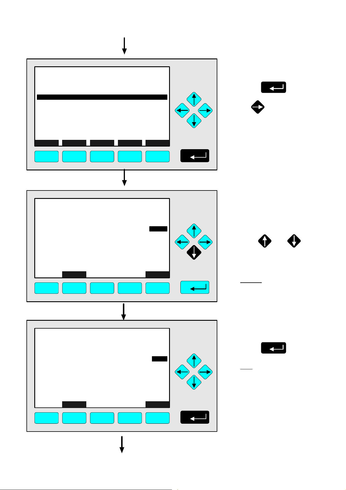
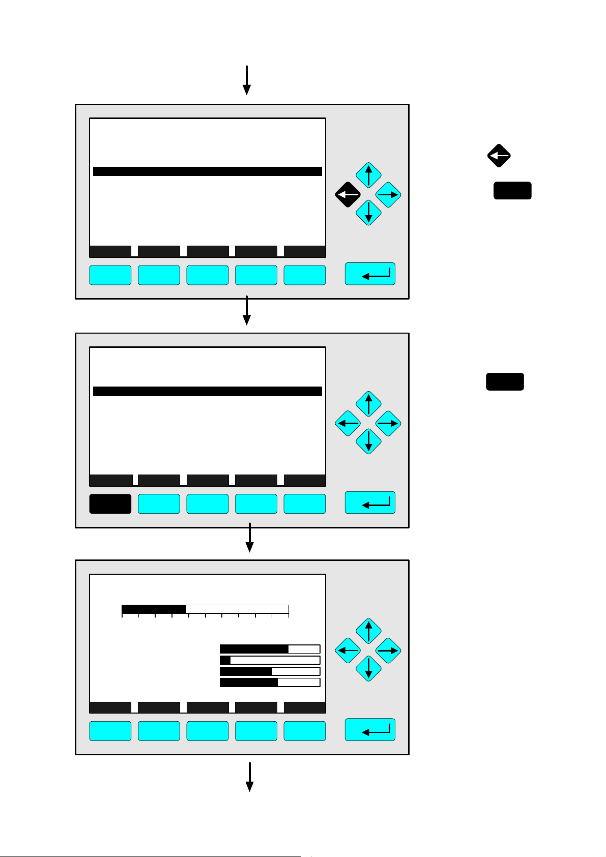
All steps are figured with detailed illustrations and operation instructions. In the left column
you can see display and keyboard of the NGA front panel. In the right column you can
read the instructions and notes. All instructions will begin with any single component
display and will end with the corresponding single component display after the setups are
done. The keys you have to press are illustrated in black. The instructions are completed
with notes and further informations.
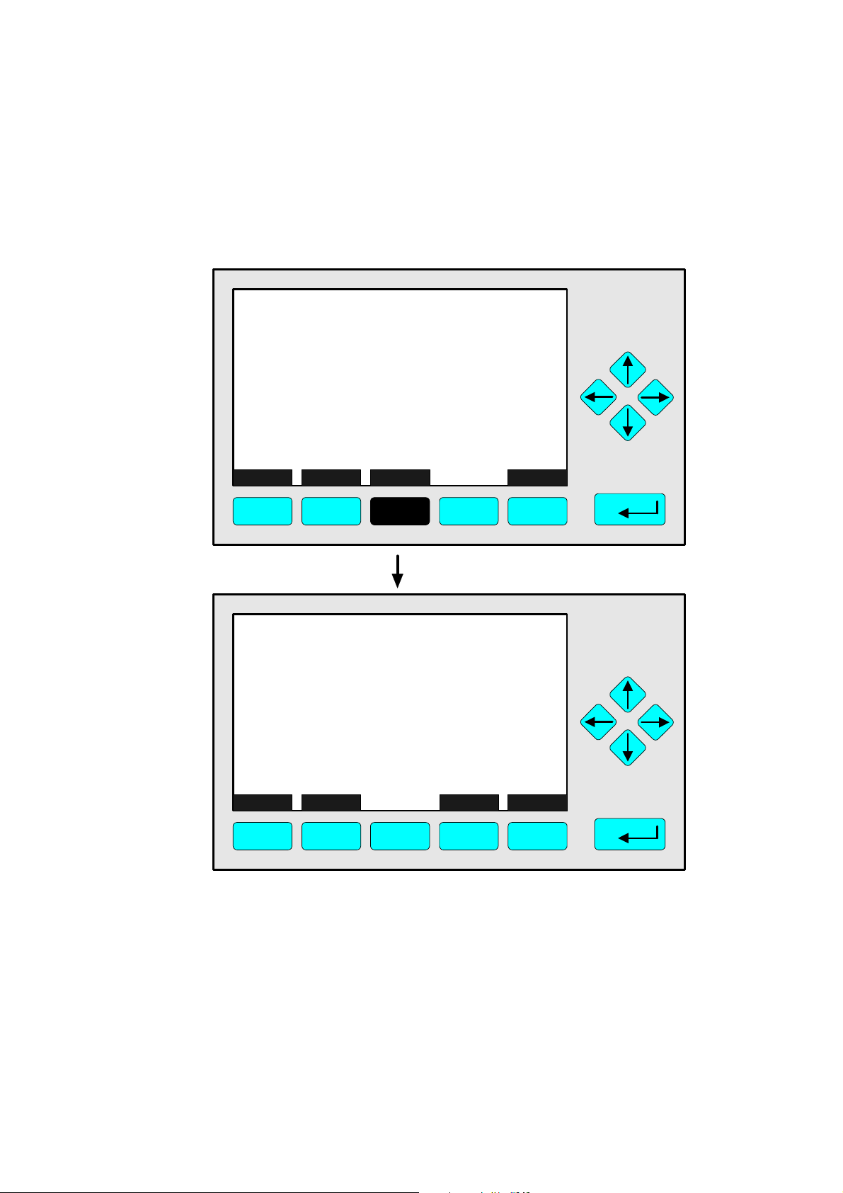
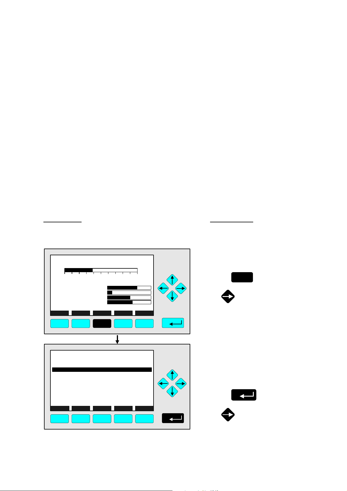
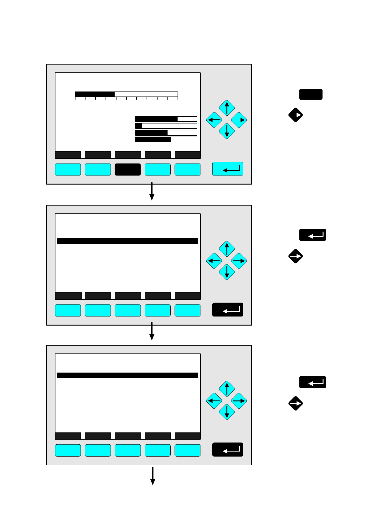
Example: You want to change from the single component display of NOx to the main menu
• Picture one shows the starting situation: single component display of NO
.
x
• If you press the F3 key you will change to menu page shown in picture 2: Main Menu.
Left column: Right column:
LCD and keyboard Instructions and notes
CLD
95.00 ppm NOx
0 250
Sample press.:
Detector temperature:
Block temperature:
Converter temp.:
DISPLAY STATUS MENU NEXT INFO
F1 F2 F3 F4 F5
CLD
Basic controls...
Expert controls and set up...
(Operational configuration)
Technical level configuration...
(Diagnostic and manufacturing/service)
MEASURE STATUS NEXT LOCK INFO
F1 F2 F3 F4 F5
Range: 4
340 hPa
0.5 C
51.5 C
360 C
95.0 ppm
Main Menu
⇒ ⇒ Change to the
Main Menu
F3
Press
or
⇒ ⇒ Next instruction
or step,
here e.g.:
Change to the
Basic Controls:
Press
or
90003479(1) [NGA-e (Software CLD 2.3/MLT 3.1.X)] 04/98
NGA 2000
4 - 1
Page 18

4 - 2
NGA 2000
90003749(1) [NGA-e (Software CLD 2.3/MLT 3.1.X)] 04/98
Page 19
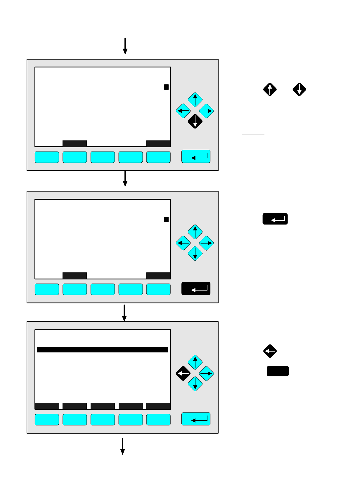
4.1.1 Measurement - Multi Component Display:
CLD
95.00 ppm NOx
0 250
Range: 4
Change of Channel
⇒ ⇒ Change to the multi
component display
F1
Press
Sample press.:
Detector temperature:
Block temperature:
Converter temp.:
DISPLAY STATUS MENU NEXT INFO
F1 F2 F3 F4 F5
CLD
95.00
45.00
333.0
150.0
20.00
SELECT STATUS TAGS OFF
F1 F2 F3 F4 F5
MLT25/CH1/R2
MLT25/CH2/R2
MLT25/CH3/R2
MLT25/CH4/R2
340 hPa
0.5 C
51.5 C
360 C
CLD
ppm NOx
ppm CO
ppm SO2
ppm NO
%O2
INFO
Note:
You can change to the
multi component display
from each single
component display.
⇒ ⇒ Enable the selecting:
">"
F1
Press
or
Note:
If no channels of other
analyzer modules are
combined to the CLD,
only the bargraph of the
CLD module will be displayed.
Then, a change of channel
will not be possible !
CLD
95.00
45.00
333.0
150.0
20.00
SELECT STATUS TAGS OFF
F1 F2 F3 F4 F5
90003749(1) [NGA-e (Software CLD 2.3/MLT 3.1.X)] 04/98
MLT25/CH1/R2
MLT25/CH2/R2
MLT25/CH3/R2
MLT25/CH4/R2
CLD
ppm NOx
ppm CO
ppm SO2
ppm NO
%O2
INFO
NGA 2000
⇒ ⇒ Select any channel
Press or
as often as necessary to
put the > - mark into the
selected line.
Example:
Change from
NOX (CLD) to
CO (MLT channel 1)
4 - 3
Page 20
CLD
95.00
45.00
333.0
150.0
20.00
CLD
ppm NOx
MLT25/CH1/R2
ppm CO
MLT25/CH2/R2
ppm SO2
MLT25/CH3/R2
ppm NO
MLT25/CH4/R2
%O2
⇒ ⇒ Change to the single
component display
of the channel
selected
F1
Press
SELECT STATUS TAGS OFF
INFO
F1 F2 F3 F4 F5
MLT25/CH1/R2
45.00 ppm CO
0 250
Temperature:
Function Control:
Maintenance Request:
Failure:
DISPLAY STATUS MENU NEXT INFO
F1 F2 F3 F4 F5
Range: 2
25.0 C
No
No
No
⇒ ⇒ Single component
display of the
channel selected
will appear
4 - 4
NGA 2000
90003749(1) [NGA-e (Software CLD 2.3/MLT 3.1.X)] 04/98
Page 21

4.1.2 Measurement - Multi Component Display:
CLD
95.00 ppm NOx
0 250
Range: 4
Sequence setup
⇒ ⇒ Change to the multi
component display
F1
Press
Sample press.:
Detector temperature:
Block temperature:
Converter temp.:
DISPLAY STATUS MENU NEXT INFO
F1 F2 F3 F4 F5
CLD
95.00
45.00
333.0
150.0
20.00
SELECT STATUS TAGS OFF
F1 F2 F3 F4 F5
MLT25/CH1/R2
MLT25/CH2/R2
MLT25/CH3/R2
MLT25/CH4/R2
340 hPa
0.5 C
51.5 C
360 C
CLD
ppm NOx
ppm CO
ppm SO2
ppm NO
%O2
INFO
⇒ ⇒ Enable the selecting:
">"
F1
Press
or
Note:
If no channels of other
analyzer modules are
combined to the CLD,
only the bargraph of the
CLD module will be displayed.
Then, the sequence setup
will not be possible !
CLD
95.00
45.00
333.0
150.0
20.00
SELECT STATUS TAGS OFF
F1 F2 F3 F4 F5
90003749(1) [NGA-e (Software CLD 2.3/MLT 3.1.X)] 04/98
MLT25/CH1/R2
MLT25/CH2/R2
MLT25/CH3/R2
MLT25/CH4/R2
CLD
ppm NOx
ppm CO
ppm SO2
ppm NO
%O2
INFO
NGA 2000
⇒ ⇒ Select the channel
for position one
Press or
as often as necessary to
put the > - mark into the
selected line.
Example:
MLT channel 2 (SO2) shall
appear at position one of the
multi component display.
4 - 5
Page 22
CLD
95.00
45.00
333.0
150.0
20.00
SELECT STATUS TAGS OFF
F1 F2 F3 F4 F5
MLT25/CH2/R2
333.0
MLT25/CH1/R2
MLT25/CH2/R2
MLT25/CH3/R2
MLT25/CH4/R2
MLT25/CH2/R2
95.00
45.00
150.0
20.00
SELECT STATUS TAGS OFF
MLT25/CH1/R2
MLT25/CH3/R2
MLT25/CH4/R2
CLD
ppm NOx
ppm CO
ppm SO2
ppm NO
%O2
ppm SO2
CLD
ppm NOx
ppm CO
ppm NO
%O2
INFO
INFO
⇒ ⇒ Assignation of the
channel selected to
position one
Press
Note:
The channel selected will
appear at position one.
All the other channels will
automatically appear one
line below their last position.
⇒ ⇒ Multi component
display will appear
with the changed
sequence
Note:
Now, you can change
to any available single
component display.
The method is described in
the last chapter (4.1.1).
F1 F2 F3 F4 F5
4 - 6
NGA 2000
90003749(1) [NGA-e (Software CLD 2.3/MLT 3.1.X)] 04/98
Page 23
CLD
95.00 ppm NOx
0 250
Range: 4
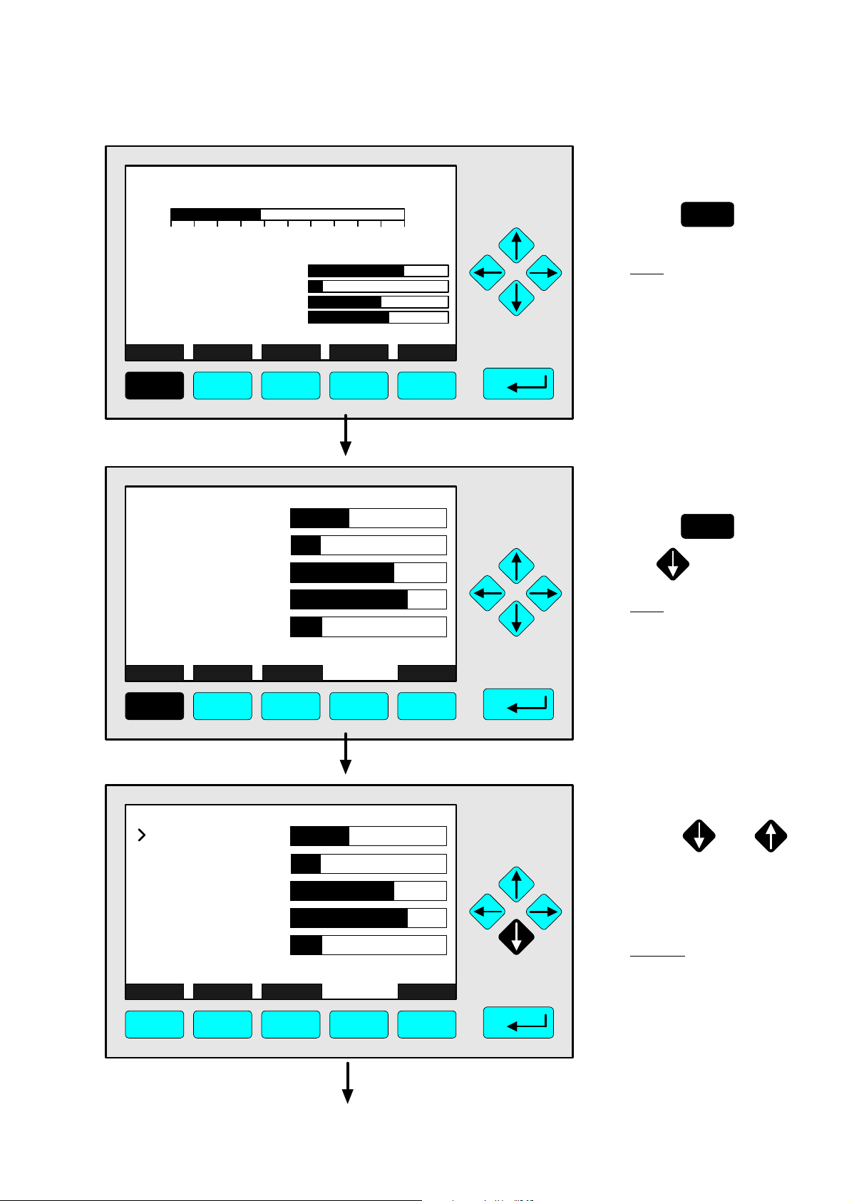
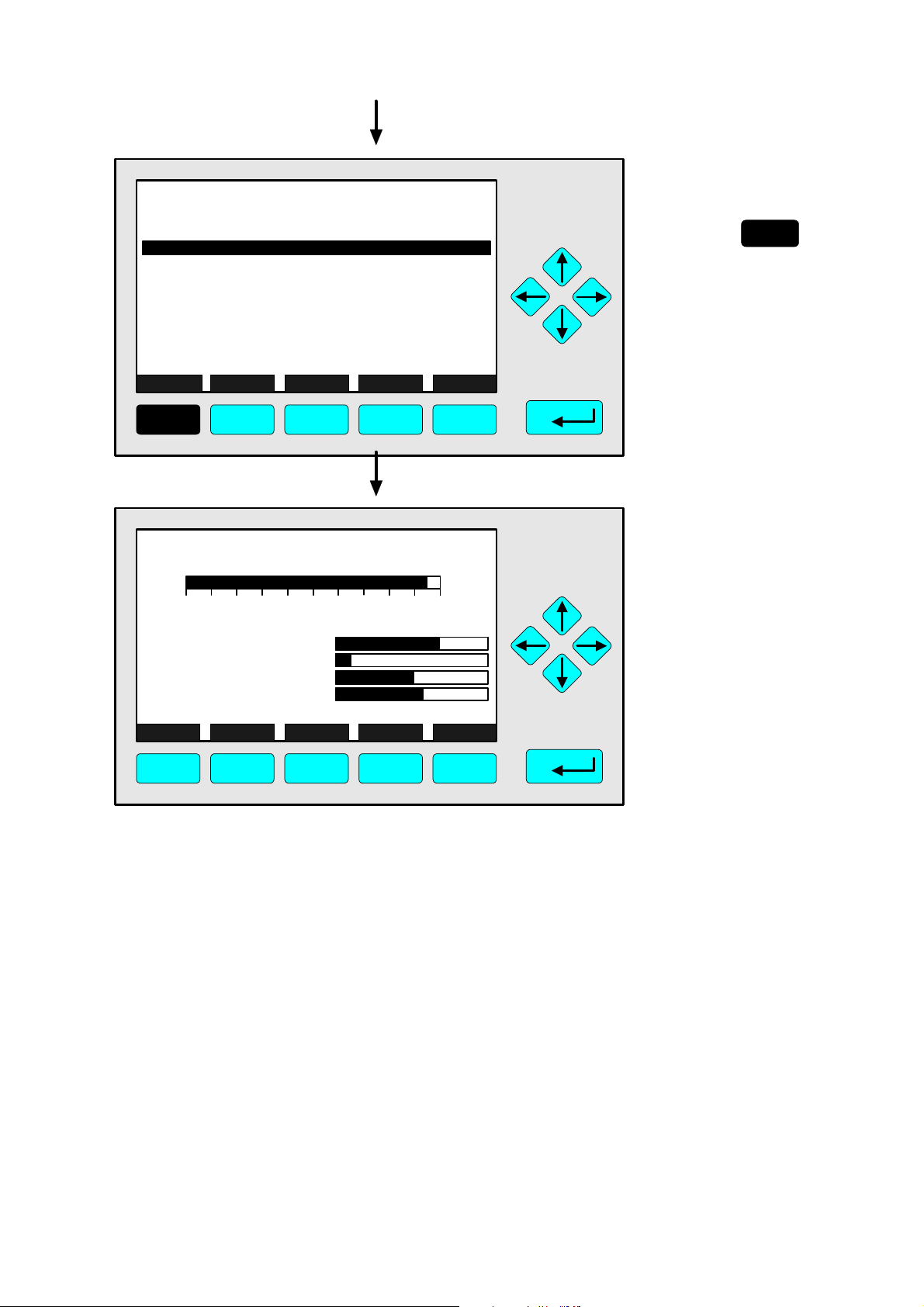
4.1.3 Measurement - Range Setting
⇒ ⇒ Change to the
main menu
F3
Press
Sample press.:
Detector temperature:
Block temperature:
Converter temp.:
DISPLAY STATUS MENU NEXT INFO
340 hPa
0.5 C
51.5 C
360 C
F1 F2 F3 F4 F5
CLD
Main Menu
Basic controls...
Expert controls and set up...
(Operational configuration)
Technical level configuration...
(Diagnostic and manufacturing/service)
MEASURE STATUS NEXT LOCK INFO
95.0 ppm
or
⇒ ⇒ Change to the
basic controls
Press
or
F1 F2 F3 F4 F5
CLD
Basic Controls
Measurement range number: 4
Range upper limit: 250.0 ppm
Range and functional control: LOCAL
Ranges with valid calibration: 4
Calibration status: READY
If it won´t calibrate...
Status: STANDBY
Measurement mode: NOx
Ozonator status: On
Ozonator power: Enabled
HOME NO/NOx ZERO SPAN INFO
95.0 ppm
F1 F2 F3 F4 F5
⇒ ⇒ Choose the
measurement
range number
Press
or
90003749(1) [NGA-e (Software CLD 2.3/MLT 3.1.X)] 04/98
NGA 2000
4 - 7
Page 24
CLD
Basic Controls
Measurement range number:
Range upper limit: 250.0 ppm
Range and functional control: LOCAL
Ranges with valid calibration: 4
Calibration status: READY
If it won´t calibrate...
Status: STANDBY
Measurement mode: NOx
Ozonator status: On
Ozonator power: Enabled
4
ESCAPE INFO
95.0 ppm
F1 F2 F3 F4 F5
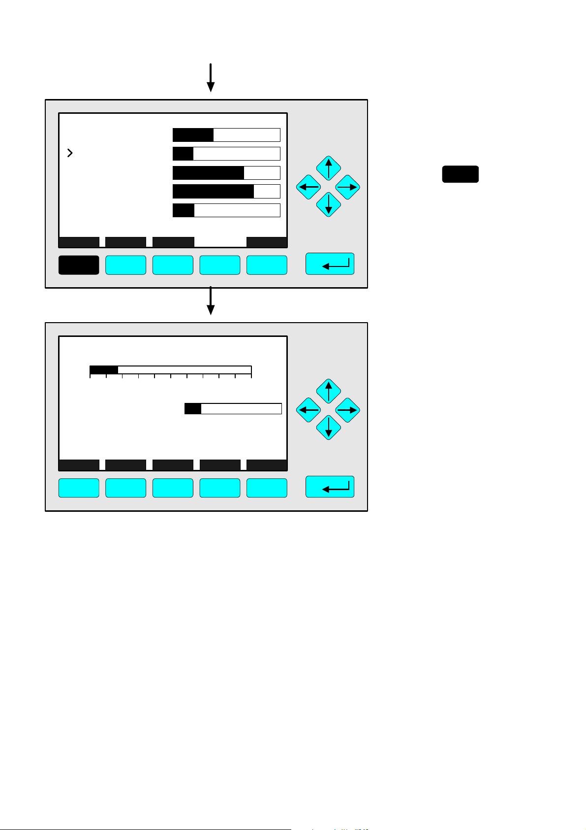
⇒ ⇒ Select the
range number
4
Press or
as often as necessary
to select another range
number.
Example:
Change from
range 4 (250 ppm) to
range 3 (100 ppm)
⇒ ⇒ Confirm the
range selected
3
Press
Note:
If you don't want to set the
new range number, you
can reactivate the former
selection:
Press F2 (ESCAPE) and
confirm it with ENTER.
CLD
Basic Controls
Measurement range number: 3
Range upper limit: 250.0 ppm
Range and functional control: LOCAL
Ranges with valid calibration: 4
Calibration status: READY
If it won´t calibrate...
Status: STANDBY
Measurement mode: NOx
Ozonator status: On
Ozonator power: Enabled
HOME NO/NOx ZERO SPAN INFO
F1 F2 F3 F4 F5
4 - 8
95.0 ppm
NGA 2000
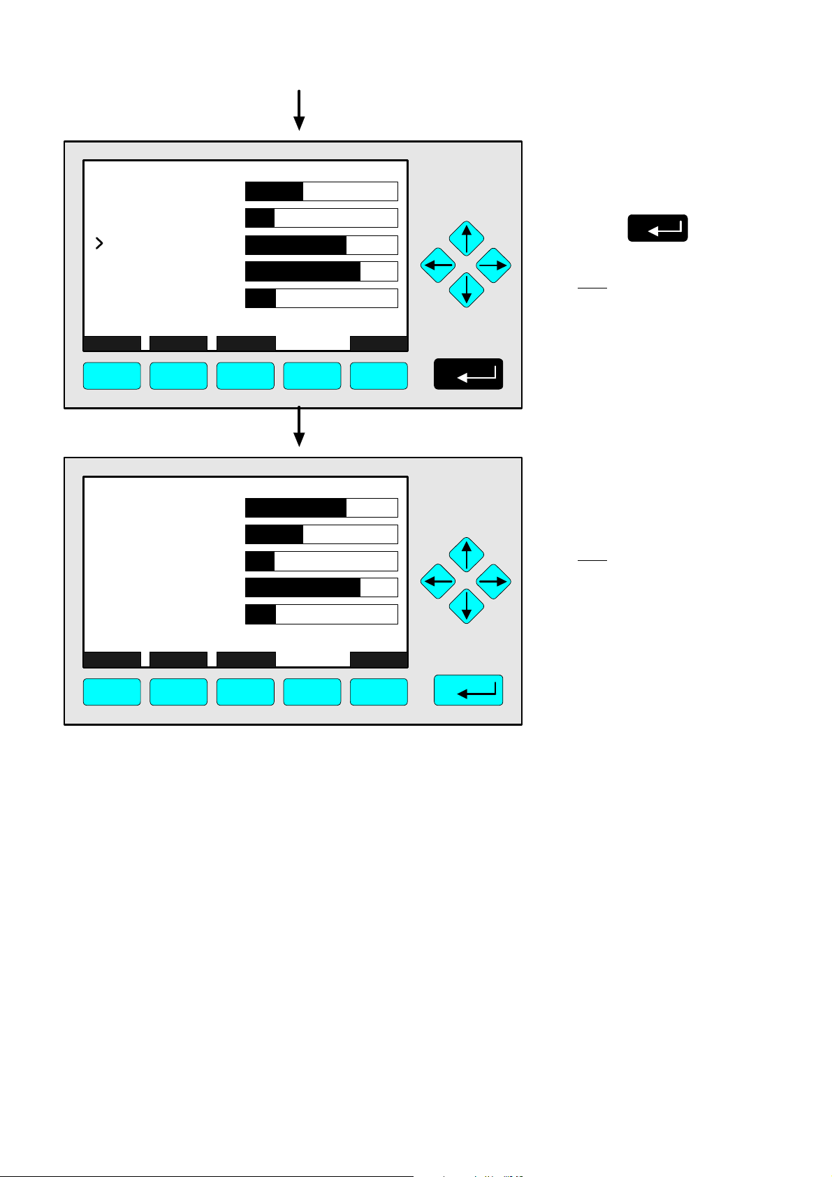
⇒ ⇒ Change to the
main menu
Press or
F1
2 times
Note:
The range upper limit (line 2)
of the range selected will be
set up automatically after the
range setting is confirmed.
90003749(1) [NGA-e (Software CLD 2.3/MLT 3.1.X)] 04/98
Page 25
CLD
Main Menu
Basic controls...
Expert controls and set up...
(Operational configuration)
Technical level configuration...
(Diagnostic and manufacturing/service)
MEASURE STATUS NEXT LOCK INFO
95.0 ppm
F1 F2 F3 F4 F5
4.1.3 Measurement - Range Setting
⇒ ⇒ Change to the single
component display
F1
Press
CLD
95.00 ppm NOx
0 100
Sample press.:
Detector temperature:
Block temperature:
Converter temp.:
DISPLAY STATUS MENU NEXT INFO
F1 F2 F3 F4 F5
Range: 3
340 hPa
0.5 C
51.5 C
360 C
⇒ ⇒ Single component
display will appear
with the new range
90003749(1) [NGA-e (Software CLD 2.3/MLT 3.1.X)] 04/98
NGA 2000
4 - 9
Page 26

4 - 10
NGA 2000
90003749(1) [NGA-e (Software CLD 2.3/MLT 3.1.X)] 04/98
Page 27
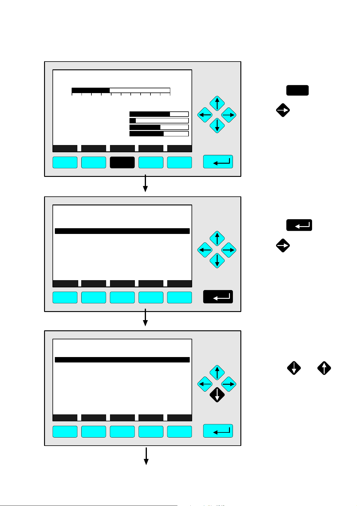
4.1.4 Measurement - Range and Functional Control
CLD
95.00 ppm NOx
0 250
Range: 4
⇒ ⇒ Change to the
main menu
F3
Press
Sample press.:
Detector temperature:
Block temperature:
Converter temp.:
DISPLAY STATUS MENU NEXT INFO
340 hPa
0.5 C
51.5 C
360 C
F1 F2 F3 F4 F5
CLD
Main Menu
Basic controls...
Expert controls and set up...
(Operational configuration)
Technical level configuration...
(Diagnostic and manufacturing/service)
MEASURE STATUS NEXT LOCK INFO
95.0 ppm
or
⇒ ⇒ Cahnge to the
basic controls
Press
or
F1 F2 F3 F4 F5
CLD
Basic Controls
Measurement range number: 4
Range upper limit: 250.0 ppm
Range and functional control: LOCAL
Ranges with valid calibration: 4
Calibration status: READY
If it won´t calibrate...
Status: STANDBY
Measurement mode: NOx
Ozonator status: On
Ozonator power: Enabled
HOME NO/NOx ZERO SPAN INFO
95.0 ppm
F1 F2 F3 F4 F5
⇒ ⇒ Change to the
line "Range and
functional control"
Press or
as often as necessary
until the line "Range and
functional control" will
appear white on black.
90003749(1) [NGA-e (Software CLD 2.3/MLT 3.1.X)] 04/98
NGA 2000
4 - 11
Page 28
CLD
Basic Controls
Measurement range number: 4
Range upper limit: 250.0 ppm
Range and functional control: LOCAL
Ranges with valid calibration: 4
Calibration status: READY
If it won´t calibrate...
Status: STANDBY
Measurement mode: NOx
Ozonator status: On
Ozonator power: Enabled
HOME NO/NOx ZERO SPAN INFO
95.0 ppm
F1 F2 F3 F4 F5
CLD
Basic Controls
Measurement range number: 4
Range upper limit: 250.0 ppm
Range and functional control:
Ranges with valid calibration: 4
Calibration status: READY
If it won´t calibrate...
Status: STANDBY
Measurement mode: NOx
Ozonator status: On
Ozonator power: Enabled
LOCAL
ESCAPE INFO
95.0 ppm
LOCAL
F1 F2 F3 F4 F5
⇒ ⇒ Choose the
parameter
Press
or
⇒ ⇒ Set up the range
and functional
control you want
++ Pay attention to
the note at p. 4-14 !
Press or
as often as necessary
to select the parameter
you want.
Options:
LOCAL, AUTO, REMOTE
CLD
Basic Controls
Measurement range number: 4
Range upper limit: 250.0 ppm
Range and functional control:
Ranges with valid calibration: 4
Calibration status: READY
If it won´t calibrate...
Status: STANDBY
Measurement mode: NOx
Ozonator status: On
Ozonator power: Enabled
LOCAL
ESCAPE INFO
F1 F2 F3 F4 F5
4 - 12
95.0 ppm
AUTO
NGA 2000
⇒ ⇒ Confirm the
parameter selected
Press
Note:
If you don't want to set the
new parameter, you can
reactivate the former
selection:
Press F2 (ESCAPE) and
confirm it with ENTER.
90003749(1) [NGA-e (Software CLD 2.3/MLT 3.1.X)] 04/98
Page 29
4.1.4 Measurement - Range and Functional Control
CLD
Basic Controls
Measurement range number: 4
Range upper limit: 250.0 ppm
Range and functional control: AUTO
Ranges with valid calibration: 4
Calibration status: READY
If it won´t calibrate...
Status: STANDBY
Measurement mode: NOx
Ozonator status: On
Ozonator power: Enabled
HOME NO/NOx ZERO SPAN INFO
F1 F2 F3 F4 F5
95.0 ppm
⇒ ⇒ Change to the
main menu
Press or
F1
2 times
CLD
Main Menu
Basic controls...
Expert controls and set up...
(Operational configuration)
Technical level configuration...
(Diagnostic and manufacturing/service)
MEASURE STATUS NEXT LOCK INFO
95.0 ppm
F1 F2 F3 F4 F5
CLD
95.00 ppm NOx
0 250
Range: 4
⇒ ⇒ Change to the single
component display
F1
Press
⇒ ⇒ Single component
display will appear
after the changing
of the range and
functional control
Sample press.:
Detector temperature:
Block temperature:
Converter temp.:
DISPLAY STATUS MENU NEXT INFO
340 hPa
0.5 C
51.5 C
360 C
F1 F2 F3 F4 F5
90003749(1) [NGA-e (Software CLD 2.3/MLT 3.1.X)] 04/98
NGA 2000
4 - 13
Page 30

⇒ ⇒ Range and functional control – Options:
• LOCAL:
The platform will be controlled via the display.
• AUTO:
The range will be selected automatically ("auto range"). This
function will only be available with an I/O board with 3 alarms
(PIN 70 656 193), because the auto ranging parameters are
located on the I/O board (see its own manual)!
• REMOTE:
The range selection will be controlled by digital inputs, e.g. via
a DIO board or I/O board with 3 alarms.
4 - 14
NGA 2000
90003749(1) [NGA-e (Software CLD 2.3/MLT 3.1.X)] 04/98
Page 31

4.1.5 Measurement - Enable/Disable Ozonator Power
CLD
95.00 ppm NOx
0 250
Range: 4
⇒ ⇒ Change to the
main menu
F3
Press
Sample press.:
Detector temperature:
Block temperature:
Converter temp.:
DISPLAY STATUS MENU NEXT INFO
340 hPa
0.5 C
51.5 C
360 C
F1 F2 F3 F4 F5
CLD
Main Menu
Basic controls...
Expert controls and set up...
(Operational configuration)
Technical level configuration...
(Diagnostic and manufacturing/service)
MEASURE STATUS NEXT LOCK INFO
95.0 ppm
or
⇒ ⇒ Change to the
basic controls
Press
or
F1 F2 F3 F4 F5
CLD
Basic Controls
Measurement range number: 4
Range upper limit: 250.0 ppm
Range and functional control: LOCAL
Ranges with valid calibration: 4
Calibration status: READY
If it won´t calibrate...
Status: STANDBY
Measurement mode: NOx
Ozonator status: On
Ozonator power: Enabled
HOME NO/NOx ZERO SPAN INFO
95.0 ppm
F1 F2 F3 F4 F5
⇒ ⇒ Change to the line
"Ozonator power"
Press or
as often as necessary
until the line "Ozonator
power" will appear white
on black.
90003749(1) [NGA-e (Software CLD 2.3/MLT 3.1.X)] 04/98
NGA 2000
4 - 15
Page 32

CLD
Basic Controls
Measurement range number: 4
Range upper limit: 250.0 ppm
Range and functional control: LOCAL
Ranges with valid calibration: 4
Calibration status: READY
If it won´t calibrate...
Status: STANDBY
Measurement mode: NOx
Ozonator status: On
Ozonator power: Enabled
HOME NO/NOx ZERO SPAN INFO
95.0 ppm
F1 F2 F3 F4 F5
CLD
Basic Controls
Measurement range number: 4
Range upper limit: 250.0 ppm
Range and functional control: LOCAL
Ranges with valid calibration: 4
Calibration status: READY
If it won´t calibrate...
Status: STANDBY
Measurement mode: NOx
Ozonator status: On
Ozonator power: Enabled
Enabled
ESCAPE INFO
95.0 ppm
Enabled
⇒ ⇒ Choose the
parameter
Press
or
⇒ ⇒ Select the ozonator
power status you
want
Press or
to select "Enabled" or
"Disabled".
F1 F2 F3 F4 F5
CLD
Basic Controls
Measurement range number: 4
Range upper limit: 250.0 ppm
Range and functional control: LOCAL
Ranges with valid calibration: 4
Calibration status: READY
If it won´t calibrate...
Status: STANDBY
Measurement mode: NOx
Ozonator status: On
Ozonator power: Enabled
Enabled
ESCAPE INFO
95.0 ppm
Disabled
F1 F2 F3 F4 F5
⇒ ⇒ Confirm the setup
Press
Note:
If you don't want to confirm
the new selection, you
can reactivate the former
one:
Press F2 (ESCAPE) and
confirm it with ENTER.
4 - 16
NGA 2000
90003749(1) [NGA-e (Software CLD 2.3/MLT 3.1.X)] 04/98
Page 33

4.1.5 Measurement - Enable/Disable Ozonator Power
CLD
Basic Controls
Measurement range number: 4
Range upper limit: 250.0 ppm
Range and functional control: LOCAL
Ranges with valid calibration: 4
Calibration status: READY
If it won´t calibrate...
Status: STANDBY
Measurement mode: NOx
Ozonator status: OFF - DISABLED
Ozonator power: Disabled
HOME NO/NOx ZERO SPAN INFO
F1 F2 F3 F4 F5
95.0 ppm
⇒ ⇒ Change to the
main menu
Press or
F1
2 times
CLD
Main Menu
Basic controls...
Expert controls and set up...
(Operational configuration)
Technical level configuration...
(Diagnostic and manufacturing/service)
MEASURE STATUS NEXT LOCK INFO
95.0 ppm
F1 F2 F3 F4 F5
CLD
95.00 ppm NOx
0 250
Range: 4
⇒ ⇒ Change to the single
component display
F1
Press
⇒ ⇒ Single component
display will appear
after the setup of
the ozonator power
status
Sample press.:
Detector temperature:
Block temperature:
Converter temp.:
DISPLAY STATUS MENU NEXT INFO
340 hPa
0.5 C
51.5 C
360 C
F1 F2 F3 F4 F5
90003749(1) [NGA-e (Software CLD 2.3/MLT 3.1.X)] 04/98
NGA 2000
4 - 17
Page 34

4 - 18
NGA 2000
90003749(1) [NGA-e (Software CLD 2.3/MLT 3.1.X)] 04/98
Page 35

4.1.6 Measurement - Measurement Mode: NO ↔↔ NO
CLD
95.00 ppm NOx
0 250
Range: 4
x
⇒ ⇒ Change to the
main menu
F3
Press
Sample press.:
Detector temperature:
Block temperature:
Converter temp.:
DISPLAY STATUS MENU NEXT INFO
340 hPa
0.5 C
51.5 C
360 C
F1 F2 F3 F4 F5
CLD
Main Menu
Basic controls...
Expert controls and set up...
(Operational configuration)
Technical level configuration...
(Diagnostic and manufacturing/service)
MEASURE STATUS NEXT LOCK INFO
95.0 ppm
or
⇒ ⇒ Change to the
basic controls
Press
or
F1 F2 F3 F4 F5
CLD
Basic Controls
Measurement range number: 4
Range upper limit: 250.0 ppm
Range and functional control: LOCAL
Ranges with valid calibration: 4
Calibration status: READY
If it won´t calibrate...
Status: STANDBY
Measurement mode: NOx
Ozonator status: On
Ozonator power: Enabled
HOME NO/NOx ZERO SPAN INFO
95.0 ppm
F1 F2 F3 F4 F5
⇒ ⇒ Select NO ↔↔ NO
x
F2
Press
to select the
measurement mode
you want.
The current selection will
be displayed in the line
"Measurement mode".
90003749(1) [NGA-e (Software CLD 2.3/MLT 3.1.X)] 04/98
NGA 2000
4 - 19
Page 36

CLD
Basic Controls
Measurement range number: 4
Range upper limit: 250.0 ppm
Range and functional control: LOCAL
Ranges with valid calibration: 4
Calibration status: READY
If it won´t calibrate...
Status: STANDBY
Measurement mode: NO
Ozonator status: On
Ozonator power: Enabled
HOME NO/NOx ZERO SPAN INFO
95.0 ppm
F1 F2 F3 F4 F5
CLD
Main Menu
Basic controls...
13.8 ppm
⇒ ⇒ Change to the
main menu
Press or
F1
2 times
⇒ ⇒ Change to the single
component display
F1
Press
Expert controls and set up...
(Operational configuration)
Technical level configuration...
(Diagnostic and manufacturing/service)
MEASURE STATUS NEXT LOCK INFO
F1 F2 F3 F4 F5
CLD
13.75 ppm NO
0 250
Sample press.:
Detector temperature:
Block temperature:
Converter temp.:
Range: 4
340 hPa
0.5 C
51.5 C
360 C
⇒ ⇒ Single component
display will appear
with the measurement mode selected
DISPLAY STATUS MENU NEXT INFO
F1 F2 F3 F4 F5
4 - 20
NGA 2000
90003749(1) [NGA-e (Software CLD 2.3/MLT 3.1.X)] 04/98
Page 37

CLD
95.00 ppm NOx
0 250
Range: 4
4.2.1 Calibration - Zeroing
⇒ ⇒ Change to the
main menu
F3
Press
Sample press.:
Detector temperature:
Block temperature:
Converter temp.:
DISPLAY STATUS MENU NEXT INFO
340 hPa
0.5 C
51.5 C
360 C
F1 F2 F3 F4 F5
CLD
Main Menu
Basic controls...
Expert controls and set up...
(Operational configuration)
Technical level configuration...
(Diagnostic and manufacturing/service)
MEASURE STATUS NEXT LOCK INFO
95.0 ppm
or
⇒ ⇒ Change to the
basic controls
Press
or
F1 F2 F3 F4 F5
CLD
Basic Controls
Measurement range number: 4
Range upper limit: 250.0 ppm
Range and functional control: LOCAL
Ranges with valid calibration: 4
Calibration status: READY
If it won´t calibrate...
Status: STANDBY
Measurement mode: NOx
Ozonator status: On
Ozonator power: Enabled
HOME NO/NOx ZERO SPAN INFO
95.0 ppm
F1 F2 F3 F4 F5
⇒ ⇒ Change to the
submenu
"Analyzer zero"
F3
Press
90003749(1) [NGA-e (Software CLD 2.3/MLT 3.1.X)] 04/98
NGA 2000
4 - 21
Page 38

CLD
Analyzer zero
Are you sure?
You must have zero gas flowing through the analyzer.
This control does NOT control any auto-calibration
module bound to this analyzer!
If you are sure, press ZERO again now.
Press the left arrow key when you are done.
Calibration status: READY
Error message for last zero: CAL OK
HOME ESCAPE ZERO INFO
95.0 ppm
F1 F2 F3 F4 F5
CLD
Analyzer zero
Are you sure?
You must have zero gas flowing through the analyzer.
This control does NOT control any auto-calibration
module bound to this analyzer!
If you are sure, press ZERO again now.
Press the left arrow key when you are done.
Calibration status: ZEROING - WAIT
Error message for last zero: CAL OK
ABORT
13.7 ppm
⇒ ⇒ Start Zeroing
++ Pay attention to
the note at p. 4-23 !
F3
Press
Caution:
You have to
• flow enough zero gas
through the analyzer
• look for a stabilized signal
before starting the zero gas
calibration.
Note:
You can go back to the
menu "Basic Controls"
with the F2 key.
⇒ ⇒ Zero gas calibration
is running
Note:
You can abort the
procedure at any time
with the F2 key.
F1 F2 F3 F4 F5
CLD
Analyzer zero
Are you sure?
You must have zero gas flowing through the analyzer.
This control does NOT control any auto-calibration
module bound to this analyzer!
If you are sure, press ZERO again now.
Press the left arrow key when you are done.
Calibration status: READY
Error message for last zero: CAL OK
HOME ESCAPE ZERO INFO
0.057 ppm
F1 F2 F3 F4 F5
⇒ ⇒ Change to the
main menu
F1
Press
Alternative:
If you want to continue with
the span gas calibration
after the zeroing is done,
you can go back to the
basic controls with the F2
key or the ←← -key.
(The spanning will be
described in the next
chapter: 4.2.2).
4 - 22
NGA 2000
90003749(1) [NGA-e (Software CLD 2.3/MLT 3.1.X)] 04/98
Page 39

CLD
Main Menu
0.017 ppm
4.2.1 Calibration - Zeroing
⇒ ⇒ Change to the
single component
display
Basic controls...
Expert controls and set up...
(Operational configuration)
Technical level configuration...
(Diagnostic and manufacturing/service)
MEASURE STATUS NEXT LOCK INFO
F1 F2 F3 F4 F5
CLD
0.017 ppm NOx
0 250
Sample press.:
Detector temperature:
Block temperature:
Converter temp.:
Range: 4
340 hPa
0.5 C
51.5 C
360 C
F1
Press
⇒ ⇒ Single component
display will appear
after the zero gas
calibration
DISPLAY STATUS MENU NEXT INFO
F1 F2 F3 F4 F5
⇒ ⇒ Notes for zero gas calibration:
• You can calibrate all ranges together or each range separately
with zero gas.
• You have to set up the parameter you want in the menu
"Calibration Parameters" (see chapter 5.1.2 S. 5-9).
90003749(1) [NGA-e (Software CLD 2.3/MLT 3.1.X)] 04/98
NGA 2000
4 - 23
Page 40

4 - 24
NGA 2000
90003749(1) [NGA-e (Software CLD 2.3/MLT 3.1.X)] 04/98
Page 41

CLD
95.00 ppm NOx
0 250
Range: 4
4.2.2 Calibration - Spanning
⇒ ⇒ Change to the
main menu
F3
Press
Sample press.:
Detector temperature:
Block temperature:
Converter temp.:
DISPLAY STATUS MENU NEXT INFO
340 hPa
0.5 C
51.5 C
360 C
F1 F2 F3 F4 F5
CLD
Main Menu
Basic controls...
Expert controls and set up...
(Operational configuration)
Technical level configuration...
(Diagnostic and manufacturing/service)
MEASURE STATUS NEXT LOCK INFO
95.0 ppm
or
⇒ ⇒ Change to the
basic controls
Press
or
F1 F2 F3 F4 F5
CLD
Basic Controls
Measurement range number: 4
Range upper limit: 250.0 ppm
Range and functional control: LOCAL
Ranges with valid calibration: 4
Calibration status: READY
If it won´t calibrate...
Status: STANDBY
Measurement mode: NOx
Ozonator status: On
Ozonator power: Enabled
HOME NO/NOx ZERO SPAN INFO
95.0 ppm
F1 F2 F3 F4 F5
⇒ ⇒ Change to the
submenu
"Analyzer span"
F4
Press
90003749(1) [NGA-e (Software CLD 2.3/MLT 3.1.X)] 04/98
NGA 2000
4 - 25
Page 42

CLD
Analyzer span
Are you sure?
You must have span gas flowing through the analyzer.
This control does NOT control any auto-calibration
module bound to this analyzer!
If you are sure, press SPAN again now.
Press the left arrow key when you are done.
Calibration status: READY
Error message for last span: CAL OK
HOME ESCAPE SPAN INFO
95.0 ppm
F1 F2 F3 F4 F5
CLD
Analyzer span
Are you sure?
You must have span gas flowing through the analyzer.
This control does NOT control any auto-calibration
module bound to this analyzer!
If you are sure, press SPAN again now.
Press the left arrow key when you are done.
Calibration status: SPANNING - WAIT
Error message for last span: CAL OK
ABORT
95.0 ppm
⇒ ⇒ Start Spanning
++ Pay attention to
the note at p. 4-27 !
F4
Press
Caution:
You have to
• flow enough span gas
through the analyzer
• look for a stable signal
before starting the span gas
calibration.
Note:
You can go back to the
menu "Basic Controls"
with the F2 key.
⇒ ⇒ Span gas calibration
is running
Note:
You can abort the
procedure at any time
with the F2 key.
F1 F2 F3 F4 F5
CLD
Analyzer span
Are you sure?
You must have span gas flowing through the analyzer.
This control does NOT control any auto-calibration
module bound to this analyzer!
If you are sure, press SPAN again now.
Press the left arrow key when you are done.
Calibration status: READY
Error message for last span: CAL OK
HOME ESCAPE SPAN INFO
225.0 ppm
F1 F2 F3 F4 F5
⇒ ⇒ Change to the
main menu
F1
Press
Alternative:
If you want to continue with
further setups of the basic
controls, you can go back to
the corresponding menu with
the F2 key or the ←← -key.
4 - 26
NGA 2000
90003749(1) [NGA-e (Software CLD 2.3/MLT 3.1.X)] 04/98
Page 43

CLD
Main Menu
Basic controls...
Expert controls and set up...
(Operational configuration)
Technical level configuration...
(Diagnostic and manufacturing/service)
MEASURE STATUS NEXT LOCK INFO
F1 F2 F3 F4 F5
225.0 ppm
4.2.2 Calibration - Spanning
⇒ ⇒ Change to the single
component display
F1
Press
⇒ ⇒ Single component
CLD
225.00 ppm NOx
display will appear
after the span gas
calibration
0 250
Sample press.:
Detector temperature:
Block temperature:
Converter temp.:
DISPLAY STATUS MENU NEXT INFO
F1 F2 F3 F4 F5
Range: 4
340 hPa
0.5 C
51.5 C
360 C
⇒ ⇒ Notes for the span gas calibration:
• You can calibrate all ranges together or each range separately with span gas. You have to set up
the parameter you want in the menu "Calibration Parameters" (see chapter 5.1.2 p. 5-9).
• If it will not be possible to calibrate all ranges with the same span gas, you have to calibrate each
range separately!
• The desired value of span gas has to be (!) a value between 10% and 110% of each end of range.
Otherwise, no calibration will be running.
Example:
• End of range 1: 50 ppm → Potential span gas setpoints: 5 – 55 ppm
• End of range 2: 250 ppm → Potential span gas setpoints: 25 – 275 ppm
• End of range 3: 1000 ppm → Potential span gas setpoints: 100 – 1100 ppm
• End of range 4: 2500 ppm → Potential span gas setpoints: 250 – 2750 ppm
90003749(1) [NGA-e (Software CLD 2.3/MLT 3.1.X)] 04/98
NGA 2000
4 - 27
Page 44

4 - 28
NGA 2000
90003749(1) [NGA-e (Software CLD 2.3/MLT 3.1.X)] 04/98
Page 45

CLD
95.00 ppm NOx
0 250
Range: 4
4.2.3 Calibration - If It Won´t Calibrate
⇒ ⇒ Change to the
main menu
F3
Press
Sample press.:
Detector temperature:
Block temperature:
Converter temp.:
DISPLAY STATUS MENU NEXT INFO
340 hPa
0.5 C
51.5 C
360 C
F1 F2 F3 F4 F5
CLD
Main Menu
Basic controls...
Expert controls and set up...
(Operational configuration)
Technical level configuration...
(Diagnostic and manufacturing/service)
MEASURE STATUS NEXT LOCK INFO
95.0 ppm
or
⇒ ⇒ Change to the
basic controls
Press
or
F1 F2 F3 F4 F5
CLD
Basic Controls
Measurement range number: 4
Range upper limit: 250.0 ppm
Range and functional control: LOCAL
Ranges with valid calibration: 4
Calibration status: READY
If it won´t calibrate...
Status: STANDBY
Measurement mode: NOx
Ozonator status: On
Ozonator power: Enabled
HOME NO/NOx ZERO SPAN INFO
95.0 ppm
F1 F2 F3 F4 F5
⇒ ⇒ Change to the line
"If it won´t calibrate..."
Press or
as often as necessary
until the line "If it won´t
calibrate..." will appear
white on black.
90003749(1) [NGA-e (Software CLD 2.3/MLT 3.1.X)] 04/98
NGA 2000
4 - 29
Page 46

CLD
Basic Controls
Measurement range number: 4
Range upper limit: 250.0 ppm
Range and functional control: LOCAL
Ranges with valid calibration: 4
Calibration status: READY
If it won´t calibrate...
Status: STANDBY
Measurement mode: NOx
Ozonator status: On
Ozonator power: Enabled
HOME NO/NOx ZERO SPAN INFO
95.0 ppm
F1 F2 F3 F4 F5
CLD
Check that you are flowing the correct gas, and the
gas concentration is what it is supposed to be.
Make sure that the reading is stable before starting.
If you have changed the range full scale value, or any
linearizer coefficients, or enabled or disabled it,
or done anything else that would affect how it
measures the gas, you may have made it hard for the
algorithm to get to a calibration.
In this case, manually adjust the coefficients
until the readings are close to correct, and try again.
HOME ESCAPE INFO
If it won´t calibrate...
95.0 ppm
⇒ ⇒ Change to the
menu page "If it
won´t calibrate..."
Press
Notes:
• Follow the instructions
on the screen
to calibrate succesfully!
• If you have further
questions, contact
your customer service,
please!
⇒ ⇒ Change to the
main menu
F1
Press
Alternative:
If you want to continue with
further setups of the basic
controls, you can go back to
the corresponding menu with
the F2 key or the ←← -key.
F1 F2 F3 F4 F5
CLD
Main Menu
Basic controls...
Expert controls and set up...
(Operational configuration)
Technical level configuration...
(Diagnostic and manufacturing/service)
MEASURE STATUS NEXT LOCK INFO
95.0 ppm
F1 F2 F3 F4 F5
⇒ ⇒ Change to the single
component display
F1
Press
4 - 30
NGA 2000
90003749(1) [NGA-e (Software CLD 2.3/MLT 3.1.X)] 04/98
Page 47

CLD
95.00 ppm NOx
4.2.3 Calibration - If It Won´t Calibrate
⇒ ⇒ Single component
display will appear
0 250
Sample press.:
Detector temperature:
Block temperature:
Converter temp.:
DISPLAY STATUS MENU NEXT INFO
Range: 4
340 hPa
0.5 C
51.5 C
360 C
F1 F2 F3 F4 F5
90003749(1) [NGA-e (Software CLD 2.3/MLT 3.1.X)] 04/98
NGA 2000
4 - 31
Page 48

4 - 32
NGA 2000
90003749(1) [NGA-e (Software CLD 2.3/MLT 3.1.X)] 04/98
Page 49

5 Expert Controls and Set up
If you press the ENTER key or the →→ -key in the line "Expert controls and set up..." of the
"Main Menu" you will change to the following display:
CLD
Expert controls and set up
Expert analyzer controls...
Auxiliary module controls...
System set up...
Analyzer module set up...
Auxiliary module set up...
System calibration...
MAIN
F1 F2 F3 F4 F5
<<<
NEXT INFO
95.0 ppm
From the menu "Expert controls and set up" you can change to several submenus to set
up parameters for the measurement and calibration of your analyzer and analyzer module.
Besides you can set up the configuration for auxiliary modules. Which part of these menus
are important for you depends on the configuration of your NGA 2000 system.
In the following table you will find a short overview about the contents of the menus and
where you will find the description in this manual:
Menu Important Contents Chapter in this manual
Expert analyzer
controls...
Auxiliary module
controls...
⇒ Zero/Span calibration
⇒ Range settings
⇒ Ozonator power
⇒ Configuration of the SIO and of
the DIO's installed in a platform
∗ 5.5 p. 53 to 60
∗ 5.2 p. 29 to 44
or in an MLT analyzer
System set up...
⇒ Front panel control
⇒ Set up of the
∗ 5.4 p. 47 to 52
single component display
⇒ Display resolution
Analyzer module set up...
⇒ Measurement/Calibration
∗ 5.1 p. 3 to 28
parameters set up
⇒ Linearizer parameters set up
⇒ Sensor/Converter/Block
parameters set up and
optimization
Auxiliary module set up...
⇒ Set up for micro processor
∗ 5.3 p. 45
controlled auxiliary I/O modules
System calibration...
⇒ Zero gas and span gas
∗ See Supplement!
calibration of all channel
automatically
90003749(1) [NGA-e (Software CLD 2.3/MLT 3.1.X)] 04/98
NGA 2000
5 - 1
Page 50

Structure of chapter five:
At the begin of any chapter you will find the way to a certain submenu of the MLT software
starting from the line "Expert controls and set up" in the "Main Menu". The way will be
described with the software catchwords that you have to enter one after another to reach
the corresponding submenu. At the end of the catchword listing you will find the illustration
of the LCD screen. After that you can read the set up instructions and explanations.
Sometimes the illustration will be completed by sketches or further menu pictures.
Example: You want to set up the zero/span gas concentrations for all ranges of the
analyzer module.
Main Menu — Expert controls and set up
↓↓
Analyzer module set up
↓↓
Calibration gas list
↓↓
CLD
Calibration Gas List
Zero gas - range 1: 0.00 ppm
NO Span gas - range 1: 2.00 ppm
NOx Span gas - range 1: 2.00 ppm
Zero gas - range 2: 0.00 ppm
NO Span gas - range 2: 25.00 ppm
NOx Span gas - range 2: 25.00 ppm
Calibration...
HOME ESCAPE MORE INFO
F1 F2 F3 F4 F5
95.0 ppm
In the menu "Calibration Gas List" you can set up the desired zero and span gas values
for all ranges. On the first menu page you will find the parameters of range 1 and 2, on the
second page you will find the parameters of range 3 and 4. You can reach the second
menu page with the F3 key (MORE)...
Further explanations and instructions to set up the parameters will follow!
5 - 2
NGA 2000
90003749(1) [NGA-e (Software CLD 2.3/MLT 3.1.X)] 04/98
Page 51

5.1 Analyzer Module Set up
Main Menu — Expert controls and set up
↓↓
Analyzer module set up
↓↓
CLD
Analyzer module set up
Calibration gas list...
Calibration parameters...
Gas measurement parameters...
Analyzer parameter list...
Physical measurement parameters...
Displayed parameters...
Analyzer tag: CLD
HOME ESCAPE INFO
F1 F2 F3 F4 F5
95.0 ppm
From the menu "Analyzer module set up" you can change to several submenus, where
you can set up the measurement and calibration parameters of the CLD analyzer module.
Besides, you can go to those submenus where you can set up the parameters of the
single component display.
Caution:
Normally, you will find "CLD" as analyzer module tag in the line "analyzer tag".
If the CLD module is part of an analyzer network: You have to change the configuration of the programmable digital inputs and analog outputs, if you change the
identification tag ! Because, the parameters of the module source will change ! So,
the relations will disappear !
Set up parameters:
♦ Select the menu line you want or the line of variables "Analyzer tag" with
the ↓↓ -key or the ↑↑ -key.
♦ Select the variable or change to the submenu with the ENTER key or the →→ -key.
♦ Select any digit with the ←← -key or the →→ -key and adjust a new value with
the ↑↑ -key or the ↓↓ -key;
Maximum of digits: 30
Options: alphabet (capital and small letters), umlauts, letters from different languages,
0, 1, 2, ..., 9, +, -, *, /, =, ?, !, %, $ and many others.
♦ Confirm the new value with the ENTER key or cancel and go back to the last value with
the F2 key.
90003749(1) [NGA-e (Software CLD 2.3/MLT 3.1.X)] 04/98
NGA 2000
5 - 3
Page 52

5.1.1 Analyzer Module Set up
Calibration/Calibration Gas List
Main Menu — Expert controls and set up
Analyzer module set up
Calibration gas list
↓↓
↓↓
↓↓
CLD
Calibration Gas List
Zero gas - range 1: 0.00 ppm
NO Span gas - range 1: 2.00 ppm
NOx Span gas - range 1: 2.00 ppm
Zero gas - range 2: 0.00 ppm
NO Span gas - range 2: 25.00 ppm
NOx Span gas - range 2: 25.00 ppm
Calibration...
HOME ESCAPE MORE INFO
F1 F2 F3 F4 F5
95.0 ppm
In the menu "Calibration Gas List" you can set up the desired zero and span gas values
for all ranges. On the first menu page you will find the parameters of range 1 and 2, on the
second page you will find the parameters of range 3 and 4. You can reach the second
menu page with the F3 key (MORE).
Via the menu line "Calibration..." you can change to the menu "Zero/span calibration",
where you can start zeroing and spanning (see next page).
Set up parameters:
♦ Select the line of variables you want or the menu line "Calibration..." with
the ↑↑ -key or the ↓↓ -key.
♦ Select the parameter or change to the menu "Zero/span calibration" with
the ENTER key or the →→ -key.
♦ Select any digit with the ←← -key or the →→ -key and adjust a new value with
the ↑↑ -key or the ↓↓ -key.
Options zero gas: 0.00 ppm up to the end of range value
Options span gas: 0.00 ppm up to 120% of the end of range value
You can set up the end of range values
in the menu "Range Settings" (see 5.1.6 p. 5-16).
♦ Confirm the new value with the ENTER key or cancel and go back to the last value
with the F2 key.
5 - 4
NGA 2000
90003749(1) [NGA-e (Software CLD 2.3/MLT 3.1.X)] 04/98
Page 53

Span gas calibration notes:
♦ The span gas setpoint of NO and NO
have to be the same value, because both
x
components will be calibrated simultaneously!
♦ You can calibrate all ranges together or each range separately with span gas. You have
to set up the parameter you want in the menu "Calibration Parameters" (see chapter 5.1.2
p. 5-9).
♦ If it will not be possible to calibrate all ranges with the same span gas, you have to
calibrate each range separately!
♦ The desired value of span gas has to be (!) a value between 10% and 110% of each end
of range. Otherwise, no calibration will be running:
• Example:
End of range 1: 50 ppm → Potential span gas setpoints: 5 – 55 ppm
End of range 2: 250 ppm → Potential span gas setpoints: 25 – 275 ppm
End of range 3: 1000 ppm → Potential span gas setpoints: 100 – 1100 ppm
End of range 4: 2500 ppm → Potential span gas setpoints: 250 – 2750 ppm
How to calibrate:
Change to the menu "Zero/span calibration" via the menu line "Calibration...":
CLD
Zero/span calibration
Measurement range number: 3
Zero gas concentration: 0.0 ppm
Span gas concentration: 100.0 ppm
Sample flow: 1100 ml/min
Raw measurement signal: 521590
Measurement gas: NOx
NO/NOx toggle!
Status: READY
Result...
Calibration adjustment limits: Disabled
HOME FACTORS ZERO SPAN INFO
F1 F2 F3 F4 F5
95.0 ppm
1) Select the measurement range:
• Press the ENTER key or the →→ -key in the line "Measurement range number" to enter
the parameter. Select the range you want to calibrate with the ↑↑ -key or the ↓↓ -key and
confirm it with ENTER. The zero gas concentration and the span gas concentration of
the range selected will appear in the corresponding lines, automatically.
2) Select the gas component:
• Go to the line "NO/NOx toggle!" with the ↓↓ -key and select the gas component you
want with the ENTER key or the →→ -key. The component selected will appear in the
line "Measurement gas", automatically.
90003749(1) [NGA-e (Software CLD 2.3/MLT 3.1.X)] 04/98
NGA 2000
5 - 5
Page 54

3) Zeroing:
• Change to the submenu "Analyzer zero" with the F3 key (ZERO).
• Pay attention to the notes on the screen !
• Flow enough zero gas through the CLD.
• Wait for a stable signal (look at the headline of the display). Then, start the zero gas
calibration with the F3 key (ZERO). The running procedure will be the same as it is
described detailed in chapter 4.2.1 of the basic controls (p. 4-22pp).
• Go back to the menu "Zero/span calibration" with the F2 key or the ←← -key after the
zero gas calibration will be done (Messages on the display: READY/CAL OK).
4) Spanning:
• Change to the submenu "Analyzer span" with the F4 key (SPAN).
• Pay attention to the notes on the screen !
• Flow enough span gas through the CLD.
• Wait for a stable signal (look at the headline of the display). Then, start the span gas
calibration with the F4 key (SPAN). The running procedure will be the same as it is
described detailed in chapter 4.2.2 of the basic controls (p. 4-26pp).
• Go back to the menu "Zero/span calibration" with the F2 key or the ←← -key after the
span gas calibration will be done (Messages on the display: READY/CAL OK).
Alternative: Go back to the "Main Menu" with the F1 key (HOME).
5) Check the calibration results:
• You can change to the submenu "Zero/span diagnostic data" via the line "Result..." of
the menu "Zero/span calibration". There you can control the results of the last zero
and span calibration. You can go back to the menu "Zero/span calibration" with the F2
key or the ←← -key.
Manual input of calibration factors:
The calibration may be wrong because of a trouble in the gas flow. If a calibration was not
successful, you have to repeat it. It is possible that a new start of calibration will not solve
the problem, if the measured zero or span gas value will differ from normal signals largely.
In that case you have to put in the calibration factors manually:
♦ From the menu "Zero/span calibration" you can change to the submenu "Calibration
Factors" with the F2 key (FACTORS):
CLD
Calibration Factors
Only those factors appropriate for the current range
will affect the reading on the current range.
Make sure you are using the right ones!
Measurement range number: 3
Range 1 factors...
Range 2 factors...
Range 3 factors...
Range 4 factors...
HOME ESCAPE INFO
F1 F2 F3 F4 F5
95.0 ppm
5 - 6
NGA 2000
90003749(1) [NGA-e (Software CLD 2.3/MLT 3.1.X)] 04/98
Page 55

♦ Select the range you want in the line "Measurement range number" and change via the
line "Range 1/2/3/4 factors..." to the corresponding submenu:
CLD
Range 3 Factors
Zero offset: 521580.6
Span factor: 0.002608716
Full scale range at calibration: 100.0 ppm
Measurement range number: 3
Raw measurement signal: 521660
HOME STORE NEXT HISTORY INFO
F1 F2 F3 F4 F5
95.0 ppm
Set up parameters:
♦ Press the ENTER key or the →→ -key in the line "Zero offset" to select the parameter and
set up "32700" resp. "524000" with the ↑↑ -key or the ↓↓ -key. You may select any digit
with the →→ -key or the ←← -key.
Note: The zero offset is about 32000 counts for the CLD software revision 2.2.1 (16 bit
D/A transformer) and about 520000 counts for the revision 2.3 (20 bit D/A transformer).
♦ Confirm your setup with the ENTER key.
♦ Go to the line "Span factor" with the ↓↓ -key.
♦ Press the ENTER key or the →→ -key to select the parameter and set up "0.00015" with
the arrow keys.
♦ Confirm your setup with the ENTER key.
Notes:
♦ You have to set up the factors for all ranges.
♦ With the parameter "Zero offset" you will fix the zero value. The changing of the zero
offset will influence the signal immediately (look at the headline).
♦ With the parameter "Span factor" you will fix the signal at the span gas setpoint. The
changing of the span factor will influence the signal immediately (look at the headline).
♦ Conditions for the manual input of factors:
• "Disabled" has to be set up in the line "Calibration adjustment limits" of the menu
"Zero/span calibration".
• "SEPARATELY" has to be set up in the lines "Zero ranges" and "Span ranges" of the
menu "Calibration Parameters" (see 5.1.2, p. 5-9).
♦ Attention:
After the calibration with factors you have to calibrate with zero gas and span gas in the
usual way!
90003749(1) [NGA-e (Software CLD 2.3/MLT 3.1.X)] 04/98
NGA 2000
5 - 7
Page 56

Saving the factors:
♦ You can store the actual zero offset and span factor with the F2 key (STORE) of the
menu "Range 1/2/3/4 Factors". You will find the stored settings on the second menu
page (see next illustration).
♦ You can change to the second menu page of the menu "Range 1/2/3/4 Factors" with
the F4 key (HISTORY):
CLD
Range 3 Factors
Zero offset: 0.000000
Span factor: 0.000000
Zero offset: 0.000000
Span factor: 0.000000
HOME NEXT RSTR MN RSTR ST INFO
F1 F2 F3 F4 F5
Manufacturer´s settings.
Stored settings
95.0 ppm
♦ You can change the stored settings against the manufacturer's settings with the F3 key
(RSTR MN: Restore the manufacturer's values). The "Zero offset" and the "Span factor"
of the first menu page will change according to the setups of the manufacturer's
settings.
♦ You can change the manufacturer's settings against the stored settings with the F4 key
(RSTR ST: Restore the "stored" values). The "Zero offset" and the "Span factor" of the
first menu page will change according to the setups of the stored settings.
5 - 8
NGA 2000
90003749(1) [NGA-e (Software CLD 2.3/MLT 3.1.X)] 04/98
Page 57

5.1.2 Analyzer Module Set up
Main Menu — Expert controls and set up
↓↓
Analyzer module set up
↓↓
Calibration parameters
↓↓
Calibration Parameters
CLD
Calibration Parameters
Calibration adjustment limits: Disabled
Calibration averaging time: 5 s
Calibration failure alarm: No
Cal. failure error allowed: 50 %
Calibration time out: 60 s
Zero ranges: TOGETHER
Span ranges: SEPARATELY
HOME ESCAPE INFO
F1 F2 F3 F4 F5
95.0 ppm
In the menu "Calibration Parameters" you can set up several parameters of the zero and
span calibration.
Set up parameters:
♦ Select the line of variables you want with the ↓↓ -key or the ↑↑ -key.
♦ Select the variable with the ENTER key or the →→ -key.
♦ Select any digit with the ←← -key or the →→ -key and adjust a new value with
the ↑↑ -key or the ↓↓ -key
resp. select the whole parameter with the ↑↑ -key or the ↓↓ -key.
♦ Confirm the new value with the ENTER key or
cancel and go back to the last value with the F2 key.
Line of variables "Calibration adjustment limits:
♦ Enabled: The calibration result will only be accepted within the limit settings. If the
results will be out of these limits, you will find a corresponding error message in the
menu "Analyzer zero" respectively "Analyzer span". Illustrations of these menus you will
find in chapter 4.2.1 p. 4-22 resp. 4.2.2 p. 4-26.
♦ Disabled: The calibration will be possible, even if the calibration results will leave the
allowed limits. Compare with the explanations in chapter 5.1.1 p. 5-6/7.
90003749(1) [NGA-e (Software CLD 2.3/MLT 3.1.X)] 04/98
NGA 2000
5 - 9
Page 58

Line of variables "Calibration averaging time":
The value in this line will determine the time range the analyzer will use to get the
calibration average. The precision will be better with longer times.
Options: 0 to 60 s; Standard: 5 s
Line of variables "Calibration failure alarm":
The accuracy of the signals may go down after a long use of the analyzer. If you will set
up "Yes" in the line "Calibration failure alarm", a warning message will display a wrong or
impossible calibration.
Line of variables "Cal. failure error allowed":
If the setpoint will differ more than allowed by the value in this line, a warning message
may be displayed. To enable this warning, "Yes" has to be set up in the line "Calibration
failure alarm".
Options: 5 to 80%; Standard: 50%
Line of variables "Calibration time out":
If the signal will not be stable after the time out set up in this line, a warning message may
be displayed. To enable this warning, "Yes" has to be set up in the line "Calibration failure
alarm".
Options: 0 to 300s; Standard: 60s
Lines of variables "Zero ranges/Span ranges":
♦ TOGETHER: All four ranges will be calibrated automatically one after another by zero
and span gas.
♦ SEPARATELY: Only the range selected will be calibrated by zero and span gas. You
have to set up this parameter, if you want to calibrate with manual factors (see chapter.
5.1.1 p. 5-6/7).
♦ Note: Only, if it is possible to get a span gas setpoint between 10% and 110% of each
end of range, you may calibrate all ranges together. Otherwise, only the ranges with
this condition will be calibrated automatically. The other ranges will be ignored!
5 - 10
NGA 2000
90003749(1) [NGA-e (Software CLD 2.3/MLT 3.1.X)] 04/98
Page 59

5.1.3 Analyzer Module Set up
Gas Measurement Parameters
Main Menu — Expert controls and set up
↓↓
Analyzer module set up
↓↓
Gas measurement parameters
↓↓
CLD
Gas Measurement Parameters
Linearization parameters...
Response time / delay parameters...
Range setting...
Units...
Linearization functions...
HOME ESCAPE INFO
F1 F2 F3 F4 F5
95.0 ppm
From the menu "Gas Measurement Parameters" you can change to several submenus,
where you can set up parameters of ranges, of measurement units and of linearization:
♦ Select the line you want with the ↓↓ -key or the ↑↑ -key.
♦ Press the ENTER key or the →→ -key to change to the corresponding menu.
90003749(1) [NGA-e (Software CLD 2.3/MLT 3.1.X)] 04/98
NGA 2000
5 - 11
Page 60

5.1.4 Analyzer Module Set up
Linearization Parameters
Main Menu — Expert controls and set up
Analyzer module set up
Gas measurement parameters
Linearization parameters
↓↓
↓↓
↓↓
↓↓
CLD
Linearization parameters
Range 1 linearizer: Disabled
If enabled, uses curve no.: 1
Range 2 linearizer: Disabled
If enabled, uses curve no.: 2
Range 3 linearizer: Disabled
If enabled, uses curve no.: 3
Range 4 linearizer: Disabled
If enabled, uses curve no.: 4
Set coefficients...
HOME ESCAPE INFO
F1 F2 F3 F4 F5
95.0 ppm
In the menu "Linearization parameters" you can enable the linearization for each range
and you can select the linearization curve.
Note:
Normally, the CLD is working linearly in the whole range. Therefore you do not have
to linearize generally ! If you will find deviations from the linearization, you should control
the ozone and sample gas supply. Optimize it, if necessary! Usually, the reason for
deviations will be a defect in the ozone supply.
Set up parameters:
♦ Select any line of variables or the menu line "Set coefficients..." with the ↓↓ -key
or the ↑↑ -key.
♦ Select the variable or change to the submenu "Linearity coefficients" with
the ENTER key or the →→ -key.
♦ Select the parameter you want with the ↑↑ -key or the ↓↓ -key.
♦ Confirm the new value with the ENTER key or
cancel and go back to the last value with the F2 key.
5 - 12
NGA 2000
90003749(1) [NGA-e (Software CLD 2.3/MLT 3.1.X)] 04/98
Page 61

Lines of variables "Range 1/2/3/4 linearizer":
In these lines you can enable the linearization for the range selected.
You have to set up "Disabled" in these lines as long as you will determine the data for
linearization. This will be necessary to avoid interferences with existing values during the
calculation of the linearization curve.
Lines of variables "If enabled, uses curve no.":
You can select for each range one of the four linearization curves from the menu
"Linearity coefficients" (see next illustration).
Menu "Linearity coefficients":
You can change to the menu "Linearity coefficients" via the line "Set coefficients...":
CLD
Linearity coefficients
A0 coefficient: 0.000000
A1 coefficient: 1.000000
A2 coefficient: 0.000000
A3 coefficient: 0.000000
A4 coefficient: 0.000000
Curve upper limit: 100.0 ppm
Curve over-range: 5.0 %
Curve under-range: 5.0 %
Status: Disabled
HOME ESCAPE NEXT LAST INFO
F1 F2 F3 F4 F5
Curve 3
95.0 ppm
In the menu "Linearity coefficients" you can put in the desired coefficients for the
linearization curve selected. With the F3 key (NEXT) you can scroll between the menu
pages of all four linearization curves. You will find the number of the curve selected in the
head line of each "Linearity coefficients" menu.
Line of variables "Curve upper limit":
In this line you should set up the end of range value for the range you want to determine
the linearization curve.
Lines of variables "Curve over-range/Curve under-range":
In these two lines you can determine how many per cent the linearization curve for the
range selected shall be over resp. under the range limits.
Line of variables "Status":
In this line you can enable or disable the linearization curve selected. This is the same
setup as in the lines "Range 1/2/3/4 linearizer" of the menu "Linearization parameters".
90003749(1) [NGA-e (Software CLD 2.3/MLT 3.1.X)] 04/98
NGA 2000
5 - 13
Page 62

5.1.5 Analyzer Module Set up
Response Time/Delay Parameters
Main Menu — Expert controls and set up
Analyzer module set up
Gas measurement parameters
Response time/delay parameters
↓↓
↓↓
↓↓
↓↓
CLD
Response time/delay parameters
Range 1 t90 time: 3.0 s
Range 2 t90 time: 3.0 s
Range 3 t90 time: 3.0 s
Range 4 t90 time: 3.0 s
LON update rate: 10 per sec
Output delay time: 0.0 s
HOME ESCAPE INFO
F1 F2 F3 F4 F5
95.0 ppm
In the menu "Response time/delay parameters" you can set up the response time (t
time) of the analyzer for each range and the output delay of the signal.
Set up parameters:
♦ Select any line of variables with the ↓↓ -key or the ↑↑ -key.
♦ Select the variable with the ENTER key or the →→ -key.
90
♦ Select any digit with the ←← -key or the →→ -key and adjust a new value with
the ↑↑ -key or the ↓↓ -key
resp. select the whole parameter with the ↑↑ -key or the ↓↓ -key.
♦ Confirm the new value with the ENTER key or
cancel and go back to the last value with the F2 key.
Lines of variables "Range 1/2/3/4 t90 time":
The t90 time is defined as the time that has to run until the analyzer displays 90% of the
current concentration after a jump in the concentration level.
Options: 0 to 30 seconds for every range of a channel.
5 - 14
NGA 2000
90003749(1) [NGA-e (Software CLD 2.3/MLT 3.1.X)] 04/98
Page 63

Line of variables "LON update rate":
In this line you can set up the update rate of the network variable.
Options: 1 per sec, 10 per sec, "ASAP" (As fast as possible)
Line of variable "Output delay time":
Example:
You can shift the absolute time of the
analog output signal for one channel. If
you use the right output delay time you
can watch the signals of several channels
at the same starting time.
Options: 0 to 30 seconds.
Conc.
CO
CO
NO
2
Time
90003749(1) [NGA-e (Software CLD 2.3/MLT 3.1.X)] 04/98
NGA 2000
5 - 15
Page 64

5.1.6 Analyzer Module Set up
Range Settings
Main Menu — Expert controls and set up
Analyzer module set up
Gas measurement parameters
Range setting
↓↓
↓↓
↓↓
↓↓
CLD
Range Settings
Minimum range: 10.0 ppm
Maximum range: 10000 ppm
Range 1 lower limit: 0.0 ppm
Range 1 upper limit: 10.0 ppm
Range 2 lower limit: 0.0 ppm
Range 2 upper limit: 25.0 ppm
Range 3 lower limit: 0.0 ppm
Range 3 upper limit: 100.0 ppm
Range 4 lower limit: 0.0 ppm
Range 4 upper limit: 250.0 ppm
HOME ESCAPE INFO
F1 F2 F3 F4 F5
95.0 ppm
In the menu "Range Settings" you can set up the begin and the end of each range. These
values will only be limited by the setups in the line "Minimum range" resp. "Maximum
range". The concentrations of these lines are manufacturer's settings and cannot be
changed by the customer.
Set up parameters:
♦ Select any line of variables with the ↓↓ -key or the ↑↑ -key.
♦ Select the variable with the ENTER key or the →→ -key.
♦ Select any digit with the ←← -key or the →→ -key and adjust a new value with
the ↑↑ -key or the ↓↓ -key
resp. select the whole parameter with the ↑↑ -key or the ↓↓ -key.
♦ Confirm the new value with the ENTER key or
cancel and go back to the last value with the F2 key.
5 - 16
NGA 2000
90003749(1) [NGA-e (Software CLD 2.3/MLT 3.1.X)] 04/98
Page 65

5.1.7 Analyzer Module Set up
Main Menu — Expert controls and set up
↓↓
Analyzer module set up
↓↓
Gas measurement parameters
↓↓
Units
↓↓
Units
CLD
Units
Gas measurement units: ppm
Pressure measurement units: hPa
Temperature measurement units: C
ppm to mg/Nm3 conversion factor: 1.000
Variables are still sent as the basic SI unit.
HOME ESCAPE INFO
F1 F2 F3 F4 F5
95.0 ppm
In the menu "Units" you can set up the units of the analyzer for pressure, temperature and
gas concentration.
Set up parameters:
♦ Select any line of variables with the ↓↓ -key or the ↑↑ -key.
♦ Select the variable with the 88 -key or the →→ -key.
♦ Select any digit with the ←← -key or the →→ -key and adjust a new value with
the ↑↑ -key or the ↓↓ -key
resp. select the whole parameter with the ↑↑ -key or the ↓↓ -key.
Options: "Gas measurement units" ppb, ppm, mg/Nm3, %
"Pressure measurement units" hPa, psig
"Temperature measurement units" C, F
"Conversion factor ppm – mg/Nm3" 0 to 100
♦ Confirm the new value with the ENTER key or
cancel and go back to the last value with the F2 key.
90003749(1) [NGA-e (Software CLD 2.3/MLT 3.1.X)] 04/98
NGA 2000
5 - 17
Page 66

5.1.8 Analyzer Module Set up
Linearization Functions
Main Menu — Expert controls and set up
Analyzer module set up
Gas measurement parameters
Linearization functions
↓↓
↓↓
↓↓
↓↓
CLD
Linearization functions
Polynomial set up...
Midpoint correction set up...
Use the polynomial set up to generate a linearizing
polynomial from up to 20 gases. With more than 6 gases
it will produce a fourth order polynomial linearizer.
Use the midpoint correction for a piecewise-linear final
correction, to bring up to three points precisely onto
the curve.
HOME ESCAPE INFO
F1 F2 F3 F4 F5
95.0 ppm
From the menu "Linearization functions" you can change to several submenus, where you
can linearize the ranges and optimize the linearization functions:
♦ Change to the line you want with the ↓↓ -key or the ↑↑ -key.
Note:
Normally, the CLD is working linearly in the whole range. Therefore you do not have
to linearize generally ! If you will find deviations from the linearization, you should control
the ozone and sample gas supply. Optimize it, if necessary! Usually, the reason for
deviations will be a defect in the ozone supply.
Polynomial set up:
Press the ENTER key or the →→ -key in the line "Polynomial set up..." to change to the
corresponding menu:
5 - 18
NGA 2000
90003749(1) [NGA-e (Software CLD 2.3/MLT 3.1.X)] 04/98
Page 67

CLD
Polynomial set up
Range to be linearized: 3
Current span gas: 100.0 ppm
Calculated polynomial order: 4
Gas values shown as: ppm
Gas concentrations...
Analyzer function: READY
HOME ESCAPE CALC INFO
F1 F2 F3 F4 F5
95.0 ppm
1) Select the range to be linearized:
• Press the ENTER key or the →→ -key in the line "Range to be linearized" to select the
parameter.
• Select the range you want with the ↑↑ -key or the ↓↓ -key and confirm it with ENTER.
2) Zeroing and Spanning of the range selected:
• e.g.: Change to the "Main Menu" with the F1 key. Change after that via the line "Basic
controls..." to the corresponding menu. Press the F3 key(ZERO) resp. the F4 key
(SPAN) to start the calibration (Look at the descriptions in the chapters 4.2.1 p. 4-21
and 4.2.2 p. 4-26).
• Alternative: Change to the menu "Zero/span calibration" of the "Expert controls" to
start the calibration (see 5.1.1 p. 5-5).
3) Determine the display of gas concentration:
• Press the ENTER key or the →→ -key in the line "Gas values shown as" to select the
parameter.
• Select the concentration setup you want with the ↑↑ -key or the ↓↓ -key and confirm it
with the ENTER key:
• "ppm" for absolute concentrations
• "Percent of span gas" for relative concentrations, i.e. the gas value will be displayed
as percentage of the span gas. This will be necessary, if you will use diluted span gas.
4) How to get the x,y-values to determine the polynomial curve:
• Press the ENTER key or the →→ -key in the line "Gas concentrations...“ to change to
the corresponding submenu:
90003749(1) [NGA-e (Software CLD 2.3/MLT 3.1.X)] 04/98
NGA 2000
5 - 19
Page 68

CLD
Gas concentrations
Gas value: -1.00
Raw reading: 0.00 ppm
Linearized value: 0.00 ppm
Gas value: -1.00
Raw reading: 0.00 ppm
Linearized value: 0.00 ppm
Point to be measured: Point 1
Analyzer function: READY
HOME ESCAPE DATA NEXT INFO
F1 F2 F3 F4 F5
Point 1
Point 2
95.0 ppm
♦ Input of the desired values:
• You will need minimum 6 values to calculate a polynomial curve. In the menu "Gas
concentration" are maximum 20 values available.
• Press the ENTER key or the →→ -key in the line "Gas value" of "Point 1" to select the
parameter.
• Set up the concentration you want with the ↑↑ -key or the ↓↓ -key. If necessary, change
the sign with the F4 key ("+/-"). Confirm your input with the ENTER key. It is also
possible to select the digits with the ←← -key or the →→ -key and to change the number
with the ↑↑ -key or the ↓↓ -key.
♦ Measuring of the raw values:
• Flow the analyzer with a defined gas concentration.
• After the signal will be stable press the F3 key (DATA): The analyzer will store the
desired value and the corresponding raw value as "Point 1" to calculate the
linearization polynom.
♦ Repeat the procedure described to get all values you need to calculate the polynom:
• Go to the line "Gas value" of "Point 2" with the ↓↓ -key and set up the desired value.
• Go to the line "Point to be measured" with the ↓↓ -key and select "Point 2".
• Measure the corresponding raw value, store the values with the F3 key and so on...
♦ To set up the values of point 3, 4 and all the other points you have to change to further
menu pages with the F4 key (NEXT). You can always go back to the last menu page
with the F2 key (ESCAPE).
5) Calculation of the polynomial function:
• You can calculate the linearization polynom in the following way, after you will be
ready with the registration of the points:
• Go back to the menu "Polynomial set up" with the F2 key (ESCAPE) or the ←← -key.
Then, press the F3 key (CALC): The analyzer will calculate the polynom with the
available points and store the coefficients of this function for the range selected.
5 - 20
NGA 2000
90003749(1) [NGA-e (Software CLD 2.3/MLT 3.1.X)] 04/98
Page 69

6) Correction of the linearization polynom, if necessary:
• You can optimize the calculated linearization with maximum three additional points.
• Press the ENTER key or the →→ -key in the line "Midpoint correction set up..." of the
menu "Linearization functions" to change to the corresponding submenu:
CLD
Midpoint correction set up
Correction: DISABLED
Point being measured: Point 3
Point 1 gas concentration: -1.00 ppm
Point 2 gas concentration: -1.00 ppm
Point 3 gas concentration: -1.00 ppm
Point 1 reading: -1.00 ppm
Point 2 reading: -1.00 ppm
Point 3 reading: -1.00 ppm
Span gas value: 0.00 ppm
Analyzer functioning: READY
HOME ESCAPE SET RANGE 4 INFO
F1 F2 F3 F4 F5
Range 3
95.0 ppm
a) Range selecting:
• Range 1 will be selected automatically after entering the menu. If you want to select
another range to correct, press the F4 key (RANGE 2/3/4). The range selected will be
displayed in the headline of the menu.
b) Disable the correction:
• You have to disable the correction mode before calculating the correction data.
Otherwise, you will have interferences during the calculation with existing values.
• Press the ENTER key or the →→ -key in the line "Correction" to select the parameter.
Set up "DISABLED" with the ↑↑ -key or the ↓↓ -key and confirm it with the ENTER key.
c) Measured point selecting:
• Go to the line "Point being measured" with the ↓↓ -key.
• Press the ENTER key or the →→ -key to select the parameter. Select "Point 1" with the
the ↑↑ -key or the ↓↓ -key and confirm it with the ENTER key.
d) Set up the gas concentration for point 1:
• Go to the line "Point 1 gas concentration" with the ↓↓ -key.
• Press the ENTER key or the →→ -key to select the parameter.
• Select any digit with the ←← -key or →→ -key and set up the value you want with the the
↑↑ -key or the ↓↓ -key. If necessary, change the sign with the F4 key ("+/-").
• Confirm your set up with the ENTER key.
e) Measuring of the gas concentrations:
• Flow the analyzer with the gas concentration set up of the line "Point 1 gas
concentration" and measure the raw value.
• After the signal will be stable press the F3 key (SET): The current signal will be
displayed in the line "Point 1 reading". But, the analyzer will equate the raw value with
the desired value of this point automatically.
90003749(1) [NGA-e (Software CLD 2.3/MLT 3.1.X)] 04/98
NGA 2000
5 - 21
Page 70

f) Set up further correction points:
• You can repeat the steps c) to e) to determine maximum two further correction points.
• Select "Point 2" resp. "Point 3" in the line "Point being measured". Set up the value
you want in the line "Point 2 gas concentration" resp. "Point 3 gas concentration".
Measure the gas concentrations and set up the correction with the F3 key.
g) Enable the correction:
• Select "ENABLED" in the line "Correction": The midpoint correction will be done auto-
matically for the range selected with the determined values.
The midpoint correction can be done for each range of the CLD analyzer module.
5 - 22
NGA 2000
90003749(1) [NGA-e (Software CLD 2.3/MLT 3.1.X)] 04/98
Page 71

5.1.9 Analyzer Module Set up
Analyzer Parameter List
Main Menu — Expert controls and set up
↓↓
Analyzer module set up
↓↓
Analyzer Parameter List
↓↓
CLD
Analyzer Parameter List
Analyzer tag: CLD
Ozonator status: OFF - PRESSURE
Ozonator power: Enabled
First line´s parameter: Sample press.:
Second line´s parameter: Detector temperature:
Third line´s parameter: Block temperature:
Fourth line´s parameter: Converter temp.:
Linearizer parameters...
HOME ESCAPE NEXT LAST INFO
F1 F2 F3 F4 F5
95.0 ppm
In the menu "Analyzer Parameter List" you can set up parameters of the single component
display, of the ozonator and the analyzer tag. You can also change to several submenus,
where you can set up linearizer parameters, concentration and calibration parameters.
Set up parameters:
♦ Select any line of variables or the menu line "Linearizer parameters..." with
the ↓↓ -key or the ↑↑ -key.
♦ Select the variable or change to the submenu "Linearity coefficients" with
the ENTER key or the →→ -key.
♦ Select any digit with the ←← -key or the →→ -key and adjust a new value with
the ↑↑ -key or the ↓↓ -key
resp. select the whole parameter with the ↑↑ -key or the ↓↓ -key.
♦ Confirm the new value with the ENTER key or
cancel and go back to the last value with the F2 key.
Line of variables "Analyzer tag":
You can input a tag of maximum thirty digits. You will find the same line in the menu
"Analyzer module set up" (see chapter 5.1 p. 5-3).
Caution:
Normally, you will find "CLD" as analyzer module tag in the line "analyzer tag".
If the CLD module is part of an analyzer network: You have to change the configuration of the programmable digital inputs and analog outputs, if you change the
identification tag ! Because, the parameters of the module source will change ! So,
the relations will disappear !
90003749(1) [NGA-e (Software CLD 2.3/MLT 3.1.X)] 04/98
NGA 2000
5 - 23
Page 72

Line of variables "Ozonator power":
Options: Enabled/Disabled
The setup of this line will change the displayed message of the line "Ozonator status".
That line is not available. The ozonator power setup is also possible in the menu "Basic
Controls" (see chapter 4.1.5 p. 4-15).
Lines of variables "First/Second/Third/Fourth line's parameter:
In these lines you can set up which of the following parameters shall be displayed in each
of the last four lines of the single component display:
♦ Sample pressure (bargraph with measured value)
♦ Sample flow (bargraph with measured value)
♦ Raw signal (bargraph with measured value)
♦ Validity (report: valid/invalid)
♦ Interference (report: On/Off)
♦ Health (report: Normal/...)
♦ Operational state (report: STANDBY/...)
♦ Measurement mode (report: 1/...)
♦ Linearizer (report: Enabled/Disabled)
♦ Calibration status (report: READY/...)
♦ Output delay time (bargraph with value selected)
♦ t
time (bargraph with value selected)
90
♦ Noise level (of concentration)
♦ NO/NO
♦ Detector temperature (bargraph with measured value)
♦ Block temperature (bargraph with measured value)
♦ Converter temperature (bargraph with measured value)
♦ Ozonator (report: OFF - ENABLED/OFF - DISABLED)
(Display: NO/NOx)
x
Menu line "Linearizer parameters...":
Via this line you can change to the submenu "Linearity coefficients", where you can set up
the coefficients of the linearization curves manual. You can also reach the menu "Linearity
coefficients" via the menu "Linearization parameters". These menus are described
detailed in chapter 5.1.4 p. 5-12/13.
Ramifications via function keys:
With the F3 key (NEXT) of the menu "Analyzer Parameter List" you can change to further
menu pages, where you can set up the following concentration and calibration parameters:
♦ Control mode
♦ Output delay time
♦ Begin and end of all four ranges
♦ t
time (response time) for all ranges
90
♦ Linearizer enabling/disabling for each range
♦ Calibration averaging time
5 - 24
NGA 2000
90003749(1) [NGA-e (Software CLD 2.3/MLT 3.1.X)] 04/98
Page 73

♦ Calibration failure alarm
♦ Calibration failure error allowed
♦ Calibration time out
♦ Zero and span gas calibration of the ranges together or separately
♦ Enabling/Disabling of the calibration adjustment limits
♦ Set up of the zero gas concentration of each range
♦ Set up of the NO and NO
span gas concentration of each range
x
You can also set up all these parameters in the menus "Calibration Gas List", "Calibration
Parameters", "Response time/delay parameters" and "Range Settings". You can find the
descriptions of these menus in the chapters 5.1.1 p. 5-4, 5.1.2 p. 5-9/10 and 5.1.5/6 p. 5-14
to 16.
With the F4 key (LAST) of the menu "Analyzer Parameter List" you can change to the
menu page "Calibration Gases", where you can set up the NO and NOx span gas
concentrations of each range. This menu page is the same page you will reach by
pressing the F3 key (NEXT) several times.
90003749(1) [NGA-e (Software CLD 2.3/MLT 3.1.X)] 04/98
NGA 2000
5 - 25
Page 74

5.1.10 Analyzer Module Set up
Physical Measurement Parameters
Main Menu — Expert controls and set up
Analyzer module set up
Physical measurement parameters
↓↓
↓↓
↓↓
CLD
Sample capillary pressure: 340 hPa
Ozone supply pressure: 1030 hPa
Ozonator status: ON
Ozonator power: Enabled
Bypass flow: 1100 ml/min
Converter temperature: 360 C
Sensor temperature: 0.5 C
Block temperature: 51.5 C
Capillary flow rate: 200 ml/min
Pressure limits...
Temperature limits...
HOME ESCAPE HISTORY INFO
F1 F2 F3 F4 F5
Physical Measurements
95.0 ppm
In the menu "Physical Measurements" you can find several physical measurement
parameters of the CLD analyzer module like ozonator power, converter temperature or
capillary flow rate. Via the menu lines "Pressure limits..." and "Temperature limits..." you
can change to the corresponding submenus, where you can set up several pressure
parameters and temperature parameters of the analyzer.
The violation of the limits in the submenus may start alarm reports, if the alarm report is
enabled in the diagnostic menus of the analyzer module (see 6.3.2 p. 6-27). Besides, the
limits of the submenus will be begin and end of the bargraphs in the single component
display, if activated (see 5.1.9 p. 5-24).
Changing to the submenus:
♦ Select the line you want with the ↑↑ -key or the ↓↓ -key.
♦ Press the ENTER key or the →→ -key to change to the corresponding submenu.
Note:
You should control the sample capillary pressure, the ozone supply pressure and the
bypass flow in this menu after starting up your CLD. The values displayed in these lines
should be equivalent to the original manufacturer's data sheet to avoid measurement
errors.
5 - 26
NGA 2000
90003749(1) [NGA-e (Software CLD 2.3/MLT 3.1.X)] 04/98
Page 75

Menu "Pressure Limits":
CLD
Sample capillary upper limit: 490.0 hPa
Sample capillary lower limit: 50.0 hPa
Ozone supply upper limit: 1050 hPa
Ozone supply lower limit: 700.0 hPa
Barometric pressure: 1013 hPa
HOME ESCAPE INFO
F1 F2 F3 F4 F5
Menu "Temperature Limits":
CLD
Converter upper limit: 500.0 C
Converter lower limit: 150.0 C
95.0 ppm
Pressure Limits
95.0 ppm
Temperature limits
Sensor upper limit: 50.0 C
Sensor lower limit: 0.0 C
Block upper limit: 55.0 C
Block lower limit: 45.0 C
HOME ESCAPE INFO
F1 F2 F3 F4 F5
Set up parameters:
♦ Select any line of variables with the ↓↓ -key or the ↑↑ -key.
♦ Select the variable with the ENTER key or the →→ -key.
♦ Select any digit with the ←← -key or the →→ -key and adjust a new value with
the ↑↑ -key or the ↓↓ -key.
♦ Confirm the new value with the ENTER key or
cancel and go back to the last value with the F2 key.
Options:
♦ Pressures: 0 to 3000 hPa
♦ Temperatures: 0 to 500 °C for converter; 0 to 75 °C for sensor and block
90003749(1) [NGA-e (Software CLD 2.3/MLT 3.1.X)] 04/98
NGA 2000
5 - 27
Page 76

5.1.11 Analyzer Module Set up
Displayed Parameters
Main Menu — Expert controls and set up
Analyzer module set up
Displayed parameters
↓↓
↓↓
↓↓
CLD
Displayed parameters
First line´s parameter: Sample press.:
Second line´s parameter: Detektor temperature:
Third line´s parameter: Block temperature:
Fourth line´s parameter: Converter temp.:
May be displayed on the appropriate
line of the single analyzer display screen.
HOME ESCAPE INFO
F1 F2 F3 F4 F5
95.0 ppm
In the menu "Displayed Parameters" you can determine which parameters shall be
displayed in the last four lines of the single component display. These are the same
parameters you can set up in the menu "Analyzer Parameter List" (see 5.1.9 p. 5-23).
Set up parameters:
♦ Select any line of variables with the ↓↓ -key or the ↑↑ -key.
♦ Select the variable with the ENTER key or the →→ -key.
♦ Select the parameter you want with the ↑↑ -key or the ↓↓ -key.
♦ Confirm the new value with the ENTER key or
cancel and go back to the last value with the F2 key.
5 - 28
NGA 2000
90003749(1) [NGA-e (Software CLD 2.3/MLT 3.1.X)] 04/98
Page 77

5.2 Auxiliary Module Controls
Main Menu — Expert controls and set up
↓↓
Auxiliary module controls
↓↓
CLD
Auxiliary module controls
Set-up SIO module...
Set-up DIO module(s)...
MAIN BACK
F1 F2 F3 F4 F5
>>> <<<
95.0 ppm
INFO
From the menu "Auxiliary module controls" you can change to some submenus where you
can set up the parameters for the SIO module and the DIO modules of the MLT analyzer
or platform:
♦ Press the ENTER key or the →→ -key in the line "Set-up SIO module..." or in the line
"Set-up DIO module(s)..." to change to the corresponding submenus.
90003749(1) [NGA-e (Software CLD 2.3/MLT 3.1.X)] 04/98
NGA 2000
5 - 29
Page 78

5.2.1 Auxiliary Module Controls
Local SIO Configuration Sections
Main Menu — Expert controls and set up
↓↓
Auxiliary module controls
↓↓
Set-up SIO module
↓↓
CLD
- LOCAL SIO CONFIGURATION SECTIONS -
Analog output setup...
Serial interface setup...
Configuration of Relay Outputs...
Module installed: Yes
EXPERT INFO
F1 F2 F3 F4 F5
95.0 ppm
From the menu "LOCAL SIO CONFIGURATION SECTIONS" you can change to
submenus to control and set up several output configurations of the auxiliary SIO module.
General Configuration of a SIO board (the whole specification is in another manual):
♦ Analog outputs: minimum 2, maximum 8
♦ Serial interface (RS 232 or RS 485) to connect the analyzer with a external computer
♦ Three relay outputs
If there is a SIO module installed in the platform or in the MLT analyzer, you have to put in
"Yes" in the line "Module installed", otherwise "No".
Set up parameters:
♦ Select the line of variables or any menu line with the ↓↓ -key or the ↑↑ -key.
♦ Select the variable or change to the submenu with the ENTER key or the →→ -key.
♦ Select the parameter with the ↑↑ -key or the ↓↓ -key.
♦ Confirm the new value with the ENTER key or cancel and go back to the last value with
the F2 key.
5 - 30
NGA 2000
90003749(1) [NGA-e (Software CLD 2.3/MLT 3.1.X)] 04/98
Page 79

Analog Output Setup:
Press the ENTER key or the →→ -key in the line "Analog output setup..." to change to the
corresponding submenu:
CLD
- ANALOG OUTPUT SETUP -
Output number: 1
Choose signal source module...
Choose signal...
Signal value for 0% output: 0.00 ppm
Signal value for 100% output: 2500.00 ppm
Output current range: 0...20 mA
Hold output during calibration? No
Signal name: NO/NOx
Current signal value: 95.00 ppm
Source module: CLD
EXPERT ADJUST INFO
F1 F2 F3 F4 F5
95.0 ppm
Configuration of the analog output:
1) Select the analog output number:
You can set up all parameters in the menu "ANALOG OUTPUT SETUP" separately for
each of the available analog outputs. The number of outputs depends on the hardware
configuration of the SIO module (minimum: 2, maximum: 8).
♦ Press the ENTER key or the →→ -key to select the output number and adjust the value
you want with the ↑↑ -key or the ↓↓ -key.
♦ Confirm the number selected with the ENTER key.
2) Choose the signal source module:
♦ Change with the ↓↓ -key to the line "Choose signal source module..."
♦ Change to the submenu "ANALYZER MODULES" with the ENTER key or the →→ -key.
The tags of all analyzer modules combined with the platform or the MLT analyzer will
appear:
CLD
- ANALYZER MODULES -
MENU BACK
F1 F2 F3 F4 F5
>>> <<<
95.0 ppm
CLD
90003749(1) [NGA-e (Software CLD 2.3/MLT 3.1.X)] 04/98
NGA 2000
5 - 31
Page 80

♦ Go to the line you want with the ↑↑ -key or the ↓↓ -key.
♦ Select the tag of the channel with the ENTER key or the →→ -key:
The display will go back to the menu "ANALOG OUTPUT SETUP" automatically.
The tag of the channel selected will appear in the line "Source module".
3) Select any signal:
♦ Change to the line "Choose signal" with the ↓↓ -key.
♦ Press the ENTER key or the →→ -key to change to the submenu "SIGNALS":
CLD
- SIGNALS -
Converter temp.:
Block temperature:
Detector temperature:
MENU BACK
F1 F2 F4 F5
>>> <<<
F3
95.0 ppm
Sample flow:
Sample press.:
Ozonator:
NO/NOx:
Noise level:
INFO
♦ Change to the line you want with the ↑↑ -key or the ↓↓ -key.
You can change with the F3 key (>>>) to further menu pages containing other available
signals:
• t
time
90
• Output delay time
• Calibration status
• Linearizer
• Measurement mode
• Operational state
• Health
• Interference
• Validity
• Raw signal
• Primary Variable
♦ Press the ENTER key or the →→ -key to select the signal:
The display will go back to the menu "ANALOG OUTPUT SETUP" automatically.
The signal selected will appear in the line "Signal name".
4) Determination of the output signal values:
You can determine the signal value for the 0% output and the 100% output in the lines
"Signal value for 0% output" or "Signal value for 100% output". So you have the possibility
to zoom out a certain part of the whole range.
5 - 32
NGA 2000
90003749(1) [NGA-e (Software CLD 2.3/MLT 3.1.X)] 04/98
Page 81

♦ Example:
• Range from 0 to 1000 ppm
• 0% value shall be 400 ppm, 100% value shall be 700 ppm
• Analog output is normally: 0V = 0 ppm 10V = 1000 ppm
• After changing the output signal: 0V = 400 ppm 10V = 700 ppm
♦ Change to the line "Signal value for 0% output" or "Signal value for 100% output" with
the ↓↓ -key.
♦ Select the value with the ENTER key or the →→ -key.
♦ Select any digit with the ←← -key or the →→ -key and adjust a new value with the ↑↑ -key or
the ↓↓ -key. Confirm it with the ENTER key.
Note:
If you change the measurement range the adjustment done in this menu will disappear
and go back to the standard values of the range! To change the output signal values
permanently, you have to change the adjustments in the menu "Range Settings"!
(see 5.1.6 p. 5-16)
Attention:
The signal range at the analog output should not be less than the littlest measurement
range. Otherwise, it is possible that the noise level will be very high at the analog output!
5) Determination of the output current range:
♦ Select to the line "Output current range" with the ↓↓ -key.
♦ Press the ENTER key or the →→ -key to select the range and select the value you want
with the ↑↑ -key or the ↓↓ -key.
♦ Confirm the new adjustment with the ENTER key.
Options: 0...20 mA (and automatically 0...10V) or 4...20 mA (2...10V).
6) Analog output during calibration:
In the line "Hold output during calibration?" you can determine the signal drift of the analog
output and of the limits during calibration:
♦ Yes: During the whole calibration the analog output signal and the status of the limits
are fixed to the last value before calibration.
♦ No: The analog output signal and the status of the limits are following to the
measurement signal during the whole calibration procedure.
Sample Gas Zeroing Spanning Sample Gas
Hold output during
calibration?
Hold output during
calibration?
No
Yes
0V
xV
Note:
♦ The adjustments "Yes/No" are valid for all kinds of calibrations of a platform SIO or MLT
analyzer SIO: manual, time controlled, AK controlled and system calibration.
90003749(1) [NGA-e (Software CLD 2.3/MLT 3.1.X)] 04/98
NGA 2000
5 - 33
Page 82

7) Fine adjustment of the analog output:
If you press the F4 key in the menu "ANALOG OUTPUT SETUP" you can change to the
submenu "OUTPUT FINE ADJUSTMENT", where you can do the fine adjustments of the
analog output:
CLD
- OUTPUT FINE ADJUSTMENT -
Output number: 1
Operation mode: Normal
Fine adjustment for 0% output: 4097
Fine adjustment for 100% output: 799
EXPERT BACK
F1 F2 F3 F4 F5
95.0 ppm
INFO
In the line "Output number" the output number selected in the menu "ANALOG OUTPUT
SETUP" will appear. If you want you can change the number in the submenu "OUTPUT
FINE ADJUSTMENT":
♦ Press the ENTER key or the →→ -key to select the output number and adjust the value
you want with the ↑↑ -key or the ↓↓ -key. Options: 1, ..., 8.
♦ Confirm the number selected with the ENTER key.
Set up fine adjustment of the analog output:
♦ Press the ENTER key or the →→ -key in the line "Operation mode" to select the
parameter and adjust one of the following parameters with the ↑↑ -key or the ↓↓ -key:
• Normal: The absolute measurement signal will be sent to the analog output.
• Adjust 0V: Coordination between the display and the analog output for 0V with fine
adjustment 0%.
• Adjust 10V: Coordination between the display and the analog output for 10V with fine
adjustment 100%.
♦ Confirm the new parameter with the ENTER key.
♦ Press the ENTER key or the →→ -key in the line "Fine adjustments for 0% output" or
"Fine adjustment for 100% output" to select the corresponding value.
♦ Adjust the value you want with the ↑↑ -key or the ↓↓ -key and confirm it with the ENTER
key. Options: 3500 - 4800 for 0% and 750 - 900 for 100%.
The last three lines of variables in the menu "Analog output setup" only display some
values of the analog output! They are not available.
5 - 34
NGA 2000
90003749(1) [NGA-e (Software CLD 2.3/MLT 3.1.X)] 04/98
Page 83

Serial interface setup:
Press the ENTER key or the →→ -key in the line "Serial interface setup..." of the menu
"LOCAL SIO CONFIGURATION SECTIONS" to change to the corresponding submenu:
CLD
- SERIAL INTERFACE SETUP -
Baudrate: 19200
Data bits: 8
Stop bits: 1
Parity: None
Echo mode: Disabled
Handshake: Xon/Xoff
Type of installed serial interface: RS232
EXPERT
F1 F2 F3 F4 F5
95.0 ppm
INFO
In the submenu "SERIAL INTERFACE SETUP" you can determine the parameters of the
data transfer between the MLT analyzer or platform and external implements. The setups
in this menu are depending on the configuration of the analyzer resp. platform and the
corresponding implement. The specification of the serial interface is described in another
manual.
Set up parameters:
♦ Select any line of variables with the ↓↓ -key or the ↑↑ -key.
♦ Select the variable with the ENTER key or the →→ -key.
♦ Select any digit with the ←← -key or the →→ -key and adjust a new value with
the ↑↑ -key or the ↓↓ -key
resp. select the whole parameter with the ↑↑ -key or the ↓↓ -key.
♦ Confirm the new value with the ENTER key or cancel and go back to the last value with
the F2 key.
Options:
Baudrate: 300 1200 2400 4800 9600 19200
Data bits: 7 8
Stop bits 1 2
Parity: None Even Odd
Echo mode: Enabled Disabled
Handshake: None Xon/Xoff
Type of installed
serial interface:
RS 232 RS 485_2X RS 485_4X None
90003749(1) [NGA-e (Software CLD 2.3/MLT 3.1.X)] 04/98
NGA 2000
5 - 35
Page 84

Configuration of Relay Outputs:
Press the ENTER key or the →→ -key in the line "Configuration of Relay Outputs..." of the
menu "LOCAL SIO CONFIGURATION SECTIONS" to change to the corresponding menu:
CLD
- CONFIGURATION of RELAY OUTPUTS -
Outputnumber: 1
Invert signal: Disabled
Choose source module...
Choose signal...
Signal comes from: NGA_Control_module
Signal name: Function control
Actual state: Off
EXPERT INFO
F1 F2 F3 F4 F5
95.0 ppm
There are three relays on any SIO board. With a jumper you can determine the relay
contact status: NO (normally opened) or NC (normally closed). Informations about the
whole specification of the SIO board you can find in another manual.
In the menu "CONFIGURATION of RELAY OUTPUTS" you have to determine the configuration of the three relay outputs!
Configuration set up:
1) Select the output number:
♦ Press the ENTER key or the →→ -key in the line "Outputnumber" and adjust the output
number one, two or three with the ↑↑ -key or the ↓↓ -key.
♦ Confirm the number selected with the ENTER key.
2) Choose the source module:
♦ Change with the ↓↓ -key to the line "Choose source module...".
♦ Change to the submenu "Analyzer Modules" with the ENTER key or the →→ -key.
(illustration see next page)
All analyzer modules joint to the platform or to the MLT analyzer and the control module
are available.
♦ Go to the line you want with the ↑↑ -key or the ↓↓ -key. If there are more than eight source
modules available you have to press the F3 key to go to another menu page.
♦ Select the tag of the module with the ENTER key or the →→ -key:
The display will go back to the menu "CONFIGURATION of RELAY OUTPUTS"
automatically. The tag of the module selected will appear in the line "Signal comes from".
5 - 36
NGA 2000
90003749(1) [NGA-e (Software CLD 2.3/MLT 3.1.X)] 04/98
Page 85

CLD
95.0 ppm
Analyzer Modules
EXPERT BACK
NGA Control module
>>> <<<
CLD
INFO
F1 F2 F3 F4 F5
3) Select any signal:
♦ Change to the line "Choose signal..." with the ↓↓ -key.
♦ Press the ENTER key or the →→ -key to change to the submenu "Signals":
CLD
Signals
MAINTENANCE REQUEST
CAL. IN PROGRESS
ZERO IN PROGRESS
SPAN IN PROGRESS
HOME ESCAPE MORE BACK INFO
95.0 ppm
NORMAL
FAILURE
ZERO FAILED
SPAN FAILED
F1 F2 F3 F4 F5
♦ Go to the line you want with the ↓↓ -key or the ↑↑ -key.
With the F3 key you can go to other menu pages containing further available signals:
• RANGE OVERFLOW
• RANGE UNDERFLOW
• FLOW TO LOW
• FLOW TO HIGH
• RANGE 1, 2, 3, 4
• OZONATOR OFF
• NOx MODE
• NO MODE
• or further signals, if need be:
90003749(1) [NGA-e (Software CLD 2.3/MLT 3.1.X)] 04/98
NGA 2000
5 - 37
Page 86

All signals of the control module and of the analyzer modules joint to the platform or MLT
analyzer (e.g. CLD, FID, MLT AM) are available in the menu "SIGNALS". The signals
shown above will appear by using a CLD module as source module.
♦ Select the signal with the ENTER key or the →→ -key:
The display will go back to the menu "CONFIGURATION of RELAY OUTPUTS"
automatically. The signal selected will appear in the line "Signal name".
4) Invert signal:
You can decide if the measurement signal should be inverted at the relay output. This can
be necessary to combine a failure with an alarm control.
♦ Press the ENTER key or the →→ -key in the line "Invert signal" to select the parameter
and adjust "Enabled" or "Disabled" with the ↑↑ -key or the ↓↓ -key.
♦ Confirm the parameter selected with the ENTER key.
The last three lines of variables in the menu "Configuration of relay outputs" only display
some adjustments of the relay output selected! They are not available:
♦ "Signal comes from:" displays the source module selected for the current relay output.
♦ "Signal name:" displays the signal selected for the current relay output.
♦ "Actual state:" displays if the relay status of the current relay is "On" or "Off".
5 - 38
NGA 2000
90003749(1) [NGA-e (Software CLD 2.3/MLT 3.1.X)] 04/98
Page 87

5.2.2 Auxiliary Module Controls
Main Menu — Expert controls and set up
↓↓
Auxiliary module controls
↓↓
Set-up DIO module(s)
↓↓
Set-up DIO module(s)
CLD
- DIO-MODULE OUTPUTS -
Inputs...
Outputnumber: 1
Choose module...
Choose signal...
Invert output: Disabled
Module status: Normal
Slot ID: 1
Signal name: ????
Signal level: Off
Signal comes from: ????
EXPERT
F1 F2 F3 F4 F5
>>>
ACKNOWL
95.0 ppm
INFO
In the menu "DIO-MODULE OUTPUTS" you can set up the output configuration of the
DIO modules combined to the control module (platform or MLT analyzer). Besides you
can change to the submenu "DIO-MODULE INPUTS" to configure the inputs of the
auxiliary DIO modules.
Every DIO module is composed of 8 digital inputs and 24 digital outputs. If there exist
several DIO modules in the platform you can change to the setup menu of each with the
F3 key. The tag number of the DIO board selected will appear in the line "Slot ID". The
changing with the F3 key is not available for MLT analyzers because only one DIO can be
installed in it.
The 24 digital outputs are composed of 3 units with 8 outputs. If there is a short circuit or
an overload in one unit it will be switched off and saved against destruction. After the
defect is removed the board is available immediately. You only have to press the F4 key.
Informations about the whole specification of the DIO board you will find in another manual.
Set up parameters:
♦ Select any line of variables or any menu line with the ↓↓ -key or the ↑↑ -key.
♦ Select the variable or change to the submenu with the ENTER key or the →→ -key.
♦ Adjust a new value or select the whole parameter with the ↑↑ -key or the ↓↓ -key.
♦ Confirm the new value with the ENTER key or cancel and go back to the last value with
the F2 key.
90003749(1) [NGA-e (Software CLD 2.3/MLT 3.1.X)] 04/98
NGA 2000
5 - 39
Page 88

Line of variables "Invert output":
Select "Enabled" in the line "Invert output" if you want to invert the measurement signal at
the actual digital output, otherwise select "Disabled". The output inversion can be necessary for instance, if you want to combine a failure with an alarm control.
The last five lines of variables in the menu "DIO-module outputs" only display some
adjustments of the DIO output selected! They are not available:
♦ "Module status:" displays the status of the current DIO board.
♦ "Slot ID:" displays the tag number of the DIO board selected.
♦ "Signal name:" displays the signal selected for the current DIO output.
♦ "Signal level:" displays the status of the signal selected.
♦ "Signal comes from:" displays the source module selected for the current DIO output.
Configuration of the DIO module inputs:
Press the ENTER key or the →→ -key in the line "Inputs..." to change to the corresponding
submenu:
CLD
- DIO-MODULE INPUTS -
Inputnumber: 1
Choose module...
Choose function...
Slot ID: 1
Signal name: ????
Signal level: Off
Signal comes from: ????
EXPERT
F1 F2 F3 F4 F5
>>>
95.0 ppm
INFO
In the menu "DIO-MODULE INPUTS" you have to determine the configuration of all of the
eight DIO module inputs!
DIO input configuration setup:
1) Select the input number:
♦ Press the ENTER key or the →→ -key in the line "Inputnumber" and adjust an input
number (1, ..., 8) with the ↑↑ -key or the ↓↓ -key.
♦ Confirm the number selected with the ENTER key.
2) Choose the module:
♦ Change with the ↓↓ -key to the line "Choose module...".
♦ Change to the submenu "ANALYZER MODULES" with the ENTER key or the →→ -key.
All modules joint to the platform or to the analyzer are available.
5 - 40
NGA 2000
90003749(1) [NGA-e (Software CLD 2.3/MLT 3.1.X)] 04/98
Page 89

CLD
95.0 ppm
Analyzer Modules
EXPERT BACK
NGA Control module
>>> <<<
CLD
INFO
F1 F2 F3 F4 F5
♦ Go to the line you want with the ↑↑ -key or the ↓↓ -key. If there are more than eight source
modules available you have to press the F3 key to go to another menu page.
♦ Select the tag of the module with the ENTER key or the →→ -key:
The display will go back to the menu "DIO-MODULE INPUTS" automatically.
The tag of the module selected will appear in the line "Signal comes from".
3) Select any function:
♦ Change to the line "Choose function..." with the ↓↓ -key.
♦ Press the ENTER key or the →→ -key to change to the submenu "FUNCTIONS":
CLD
EXPERT BACK
- FUNCTIONS -
SYS:Zero/Span-Cal
>>> <<<
95.0 ppm
AM:Zero-Cal
AM:Span-Cal.
AM:Range-1
AM:Range-2
AM:Range-3
AM:Range-4
SYS:Zero-Cal
INFO
F1 F2 F3 F4 F5
♦ Go to the line you want with the ↓↓ -key or the ↑↑ -key. With the F3 key you can go to
other menu pages containing further available signals:
• SYS:Program-Cal
• SYS:Cancel-Cal
• SYS:CAL-Test-Mode
• SYS:AM-Zero-Gas
90003749(1) [NGA-e (Software CLD 2.3/MLT 3.1.X)] 04/98
NGA 2000
5 - 41
Page 90

• SYS:AM-Span-Gas1, 2, 3, 4
• SYS: Function control
• AM: Hold Outputs
• CLD-AM: NOx
♦ Select the function with the ENTER key or the →→ -key:
The display will go back to the menu "DIO-MODULE INPUTS" automatically.
The function selected will appear in the line "Signal name".
The last four lines of variables in the menu "DIO-module inputs" only display some adjustments of the DIO input selected! They are not available:
♦ "Slot ID:" displays the tag number of the DIO board selected. If there exist several DIO
modules in the platform you can change to the setup menu of each with the F3 key.
The tag number of the DIO board selected will appear in the line "Slot ID".
♦ "Signal name:" displays the signal selected for the current DIO input.
♦ "Signal level:" displays the status of the signal selected.
♦ "Signal comes from:" displays the source module selected for the current DIO input.
Configuration of the DIO module outputs:
1) Select the output number:
♦ Press the ENTER key or the →→ -key in the line "Outputnumber" of the menu
"DIO-MODULE OUTPUTS" and adjust an output number (1, ..., 24) with the
↑↑ -key or the ↓↓ -key.
♦ Confirm the number selected with the ENTER key.
2) Choose the module:
♦ Change with the ↓↓ -key to the line "Choose module...".
♦ Change to the submenu "ANALYZER MODULES" with the ENTER key or the →→ -key.
All modules joint to the platform or to the analyzer are available:
CLD
Analyzer Modules
NGA Control module
EXPERT BACK
F1 F2 F3 F4 F5
>>> <<<
95.0 ppm
CLD
INFO
5 - 42
NGA 2000
90003749(1) [NGA-e (Software CLD 2.3/MLT 3.1.X)] 04/98
Page 91

♦ Go to the line you want with the ↑↑ -key or the ↓↓ -key. If there are more than eight source
modules available you have to press the F3 key to go to another menu page.
♦ Select the tag of the module with the ENTER key or the →→ -key:
The display will go back to the menu "DIO-MODULE OUTPUTS" automatically.
The tag of the module selected will appear in the line "Signal comes from".
3) Select any signal:
♦ Change to the line "Choose signal..." with the ↓↓ -key.
♦ Press the ENTER key or the →→ -key to change to the submenu "Signals":
CLD
Signals
MAINTENANCE REQUEST
CAL. IN PROGRESS
ZERO IN PROGRESS
SPAN IN PROGRESS
HOME ESCAPE MORE BACK INFO
F1 F2 F3 F4 F5
95.0 ppm
NORMAL
FAILURE
ZERO FAILED
SPAN FAILED
♦ Go to the line you want with the ↓↓ -key or the ↑↑ -key. With the F3 key you can go to
other menu pages containing further available signals:
• RANGE OVERFLOW
• RANGE UNDERFLOW
• FLOW TO LOW
• FLOW TO HIGH
• RANGE 1, 2, 3, 4
• OZONATOR OFF
• NOx MODE
• NO MODE
• and further signals, if need be:
All signals of the control module and of the analyzer modules joint to the platform
or MLT analyzer (e.g. CLD, FID, MLT AM) are available in the menu "SIGNALS".
The signals shown above will appear by using a CLD module as source module.
♦ Select the signal with the ENTER key or the →→ -key:
The display will go back to the menu "DIO-MODULE OUTPUTS" automatically. The
signal selected will appear in the line "Signal name".
90003749(1) [NGA-e (Software CLD 2.3/MLT 3.1.X)] 04/98
NGA 2000
5 - 43
Page 92

5 - 44
NGA 2000
90003749(1) [NGA-e (Software CLD 2.3/MLT 3.1.X)] 04/98
Page 93

5.3 Auxiliary Module Set up
Main Menu — Expert controls and set up
↓↓
Auxiliary module set up
↓↓
CLD
Select any auxiliary module for set up.
Parameter: 3
MAIN BACK
F1 F2 F3 F4 F5
Auxiliary module set up
>>> <<<
95.0 ppm
INFO
In the menu "Auxiliary module set up" you can select any of the following types of micro
processor controlled auxiliary modules:
1) I/O Module with three alarms
2) Autocal I/O
3) Syscal I/O
If one of these auxiliary modules is available you will find its corresponding tag in a line of
this menu. If there exist more than eight of such modules you can change to another
menu page with the F3 key.
Press the ENTER key or the →→ -key in the line where the tag of the module is displayed to
change to the setup submenus of the corresponding I/O board.
For further Informations please contact your customer service or look at the manual of the
I/O board!
90003749(1) [NGA-e (Software CLD 2.3/MLT 3.1.X)] 04/98
NGA 2000
5 - 45
Page 94

5 - 46
NGA 2000
90003749(1) [NGA-e (Software CLD 2.3/MLT 3.1.X)] 04/98
Page 95

5.4 System Set Up
Main Menu — Expert controls and set up
↓↓
System set up
↓↓
CLD
System Set Up
Front panel control...
Display resolution...
Auxiliary lines...
HOME ESCAPE INFO
F1 F2 F3 F4 F5
95.0 ppm
From the menu "System Set Up" you can change to several submenus to set up different
parameters of the LCD and the single component display of the platform.
♦ Scroll with the ↓↓ -key or the ↑↑ -key to select the menu line you want.
♦ Press the ENTER key or the →→ -key in the line selected to change to the corresponding
submenu.
90003749(1) [NGA-e (Software CLD 2.3/MLT 3.1.X)] 04/98
NGA 2000
5 - 47
Page 96

5.4.1 System Set Up
Front panel control
Main Menu — Expert controls and set up
↓↓
System set up
↓↓
Front panel control
↓↓
CLD
Front Panel Control
LCD brightness: 70 %
LCD viewing angle: 25 %
Beeper enable: Off
Beeper frequency: 1.00 kHz
Reading refresh rate: 1 s
Drop out of menus after: 10 min
Date and time...
HOME ESCAPE INFO
F1 F2 F3 F4 F5
95.0 ppm
In the menu "Front panel control" you can set up several display parameters.
Set up parameters:
♦ Select any line of variables or the menu line with the ↓↓ -key or the ↑↑ -key.
♦ Select the variable with the ENTER key or the →→ -key.
♦ Select any digit with the ←← -key or the →→ -key and adjust a new value with
the ↑↑ -key or the ↓↓ -key
resp. select the whole parameter with the ↑↑ -key or the ↓↓ -key.
♦ Confirm the new value with the ENTER key or cancel and go back to the last value with
the F2 key.
Lines of variables "LCD brightness" and "LCD viewing angle":
In these two lines you can determine the quality of the LCD reproduction. The best values
depend on your position to the screen and on the light of the environment.
♦ Options: 20 to 100% for LCD brightness and 10 to 80% for LCD viewing angle.
♦ Usually: 70 to 90% (brightness) and 20 to 30% (angle).
♦ Caution: Be careful with the changing of these values! Perhaps you can not read the
display any longer if you use very extreme values! It is not possible to load standard
values via keyboard!
Lines of variables "Beeper enable" and "Beeper frequency":
The functionality of these two lines is not available at the moment!
5 - 48
NGA 2000
90003749(1) [NGA-e (Software CLD 2.3/MLT 3.1.X)] 04/98
Page 97

Line of variables "Reading refresh rate":
In this line you can determine how often the display shall be built up in a certain time
interval. Options: 1s to 60s. Standard: 1s.
Line of variables "Drop out of menus after":
In this line you can decide if and after which time without front panel operations the display
shall change from the current menu to the single component display.
♦ Options: 10s, 30s, 1min, 5min, 10min, 30min, Never.
Date and time set up:
Press the ENTER key or the →→ -key in the line "Date and time..." to change to the
corresponding submenu:
CLD
Date and Time
Time display format (am/pm): 24 Hrs
Network updating: Enabled
Minutes: 0
Hours: 12
(Entered as 24Hrs format)
Day: 21
Month: 2
Year: 1998
Current time: 13:48:20 21 Feb 1998
HOME ESCAPE SET INFO
F1 F2 F3 F4 F5
95.0 ppm
In the menu "Date and Time" you can set up the date and the time of the control module
(platform or MLT analyzer).
Line of variables "Time display format (am/pm)":
In this line you can decide if the time of the control module should be displayed in the 12
hours format or in the 24 hours format.
Line of variables "Network updating":
Select "Enabled" if you want that all modules combined with the platform or the MLT
analyzer can use the date and time setup of the control module. Else, select "Disabled".
Set up a new date or time:
1) Press the ENTER key or the →→ -key in the line "Minutes", "Hours", "Day", "Month" or
"Year" to select the corresponding number.
2) Select any digit with the ←← -key or the →→ -key and adjust a new value with the ↑↑ -key or
the ↓↓ -key.
♦ Options: Minutes: 0 to 59, Hours: 0 to 23, Day: 1 to 28/30/31 depending on the month
selected, Month: 1 to 12, Year: 1996 to 2035.
3) Press the F4 key to set the new date or time. The new adjustment will appear in the line
"Current time". The display in this line will be refreshed every five second.
90003749(1) [NGA-e (Software CLD 2.3/MLT 3.1.X)] 04/98
NGA 2000
5 - 49
Page 98

5.4.2 System Set Up
Display resolution
Main Menu — Expert controls and set up
↓↓
System set up
↓↓
Display resolution
↓↓
CLD
Display resolution
Maximum total number of digits: 4
Digits after the decimal point: 2
HOME ESCAPE INFO
F1 F2 F3 F4 F5
95.0 ppm
In the menu "Display resolution" you can determine the number of digits for the display of
the measured values. These numbers do not alter the accuracy of measurement. The
adjustments are not valid for the analyzer module!
Set up parameters:
♦ Select one of the two lines of variables with the ↓↓ -key or the ↑↑ -key.
♦ Select the number with the ENTER key or the →→ -key.
♦ Select the digit with the ↑↑ -key or the ↓↓ -key.
Options: Maximum total number of digits: 3, 4, 5, 6
Digits after the decimal point: 0, 1, 2, 3.
♦ Confirm the new value with the ENTER key or cancel and go back to the last value with
the F2 key.
Example:
♦ Measured number: 1.2345
♦ Select 3 for total number of digits and 2 for digits after decimal point.
♦ The screen will display: 1.23
5 - 50
NGA 2000
90003749(1) [NGA-e (Software CLD 2.3/MLT 3.1.X)] 04/98
Page 99

5.4.3 System Set Up
Main Menu — Expert controls and set up
↓↓
System set up
↓↓
Auxiliary lines
↓↓
Auxiliary Lines
CLD
Auxiliary lines
First auxiliary line: Enabled
Second auxiliary line: Enabled
Third auxiliary line: Enabled
Fourth auxiliary line: Enabled
First line source...
Second line source...
Third line source...
Last line source...
HOME ESCAPE NEXT INFO
F1 F2 F3 F4 F5
95.0 ppm
In the menu "Auxiliary lines" you can determine if the last four lines in the single
component display of the current channel shall appear. If you want to set up the lines of
the other channels of the joint analyzer modules, press the F3 key.
Set up parameters:
♦ Select any line of variables or any menu line with the ↓↓ -key or the ↑↑ -key.
♦ Select the parameter with the ENTER key or the →→ -key.
♦ Select "Enabled" or "Disabled" with the ↑↑ -key or the ↓↓ -key to enable or disable the
display of the corresponding auxiliary line in the single component display.
♦ Confirm the parameter selected with the ENTER key or cancel and go back to the last
adjustment with the F2 key.
Choose the source module for the auxiliary lines:
Press the ENTER key or the →→ -key in the line "First line source...", "Second line
source...", "Third line source..." or "Last line source..." to change to the corresponding
submenu. The tags of all modules combined with the platform or the MLT analyzer are
available:
90003749(1) [NGA-e (Software CLD 2.3/MLT 3.1.X)] 04/98
NGA 2000
5 - 51
Page 100

CLD
First auxiliary line source
Select the module to use as source for this line
in the single analyzer display screen.
HOME ESCAPE MORE BACK INFO
95.0 ppm
CLD
F1 F2 F3 F4 F5
♦ Go to the line you want with the ↑↑ -key or the ↓↓ -key. If there are more than eight source
modules available you have to press the F3 key to go to another menu page.
♦ Select the tag of the module with the ENTER key or the →→ -key:
The display will go back to the menu "Auxiliary lines" automatically.
The selection will be done.
5 - 52
NGA 2000
90003749(1) [NGA-e (Software CLD 2.3/MLT 3.1.X)] 04/98
 Loading...