

Page 1
Embedded Power for
Business-Critical Continuity
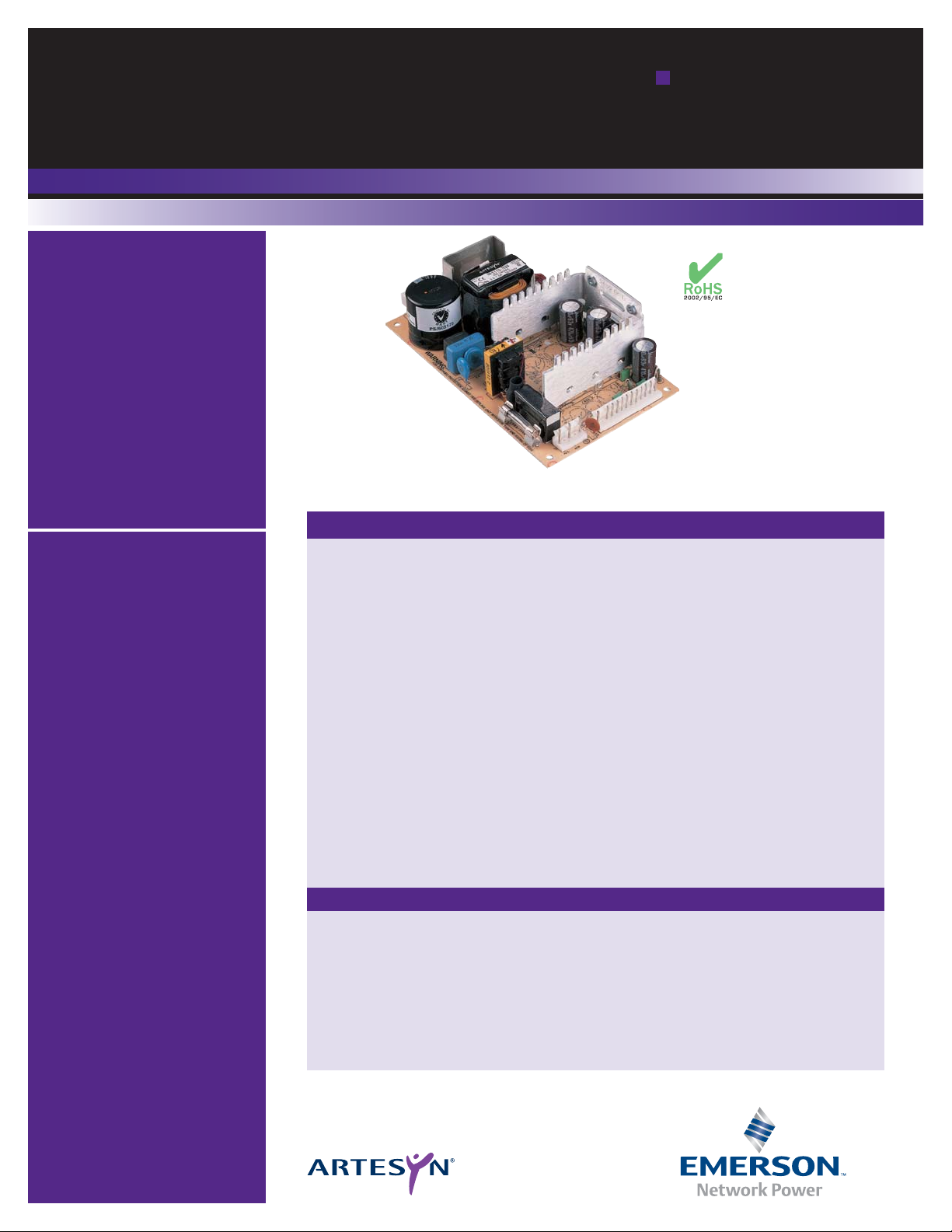
NFS110 Medical
Series
Single and
quad output
Special Features
• 7.0 x 4.25 x 1.8 inch package
• Medical, dental and
laboratory applications
• Overvoltage and short circuit
protection
• 110 W with 20 CFM
• UL, VDE and CSA safety
approvals
• EN60601-1 and UL2601
medical approvals
• Available RoHS compliant
• 2 year warranty
Total Power: 80 - 110 W
Input Voltage: 90 - 253 Vac
127 - 357 Vdc
# of Outputs: Single, quad
Safety
VDE0805/EN60601-1/
IEC601/IEC1010
File No. 10401-3336-1049
Licence No. 2874
UL2601 File No. E147937
CSA C22.2 No. 125
File No. LR41062C
Rev. 06.10.08
NFS110 Series
1 of 5
Electrical Specifications
Output
Voltage adjustability +5.1 V o/p on multi’s ±3.0%
5.1 V single output ±3.0%
12 V single output 12-14 V
15 V single output 15-18 V
24 V single output 24-30 V
Line regulation LL to HL, FL ±0.1% max.
All outputs on all units
Overshoot/undershoot At turn-on no lead 0%
Temperature coefficient All outputs ±0.02%/°C
Overvoltage protection Multi o/p 5.1 V only 6.25 V ±0.75 V
5.1 V single 6.25 V ±0.75 V
12 V single 15.75 V ±1.0 V
15 V single 22 V ±1.5 V
24 V single 33 V ±2.5 V
Output power limit Primary power Pin max. 160 W
limited Pout min. 110 W
Short circuit protection Burst mode operation
Input
Input voltage range 90-253 Vac
127-357 Vdc
Input frequency range 47-440 Hz
Input surge current 110 Vac. 50 Hz 17 A
230 Vac. 50 Hz 35 A
Safety ground leakage current 132 Vac 50 μA
264 Vac 100 μA
All specifications are typical at nominal input, full load at
25
°C unless otherwise stated
Page 2

Rev. 06.10.08
NFS110 Series
2 of 5
Embedded Power for
Business-Critical Continuity
Environmental Specifications
Thermal performance Operating, see curve 0° C to +70 °C
(See notes 9, 10) Non-operating -40 °C to +85 °C
0 °C to 50 °C amb. convection cooled 80 W
+50 °C to +70 °C,
amb. convection cooled
Derate 2 W/°C
0 °C to +50 °C, 20 CFM forced air 110 W
+50 °C to +70 °C, 20CFM forced air Derate 2.75 W/°C
Peak, 0 °C to +50 °C, max. 60 seconds 110W
Relative humidity Non-condensing 5% to 95% RH
Altitude Operating 10,000 feet max.
Non-operating 40,000 feet max.
Vibration (See Note 11) 5-500 Hz 2.4 G rms peak
EMC Characteristics
Conducted emissions EN55022, FCC part 15 Level A
Radiated emissions EN55022, FCC part 15 Level A
ESD air EN61000-4-2, level 3 Perf. criteria 1
ESD contact EN61000-4-2, level 4 Perf. criteria 1
Surge EN61000-4-3, level 3 Perf. criteria 1
Fast transients EN61000-4-4, level 3 Perf. criteria 1
Radiated immunity EN61000-4-5, level 3 Perf. criteria 2
Conducted immunity EN61000-4-6, level 3 Perf. criteria 2
General Specifications
Hold-up time 110 Vac @ 80 W 35 ms
110 Vac @ 110 W 17 ms
230 Vac @ 80 W 140 ms
230 Vac @ 110 W 100 ms
Efficiency Multiple outputs 70% typical
+5.1 V single 70% typical
12 V and 15 V singles 72% typical
24 V single 75% typical
Isolation voltage Input/output 4000 Vac
Input/chassis 1500 Vac
Approvals and standards
(see note 12)
VDE0750, IEC60601,
IEC1010, UL2601
CSA C22.2 No. 125
Weight Singles 550 g (19.4 oz)
Multiple outputs 600 g (21.2 oz)
MTBF (@25º C) MIL-HDBK-217E 125,000 hours min.
Page 3

Rev. 06.10.08
NFS110 Series
3 of 5
Embedded Power for
Business-Critical Continuity
Notes
1 Convection cooled, 80 W maximum.
2 Peak outputs lasting less than 60 seconds with duty cycle less than 10%. Total
peak power must not exceed 110 W.
3 Forced air, 20 CFM at 1 atmosphere, 110 W maximum.
4 Figure is peak-to-peak. Output ripple is measured across a 50 MHz bandwidth
using a 12 inch twisted pair terminated with a 47 μF capacitor.
5 Total regulation is defined at the static output regulation at 25 °C, including
initial tolerance, line voltage within stated limits and output voltages adjusted
to their factory settings. Also for NFS110-7902PJ, for 24 V output stated
regulation I
A
/ IB² 5. This output will maintain ±5.0% regulation if
I
A
² 5 A, where IA= +5.1 V output current and IB= +24 V output current.
6 Single output models have floating outputs which may be referenced as either
positive or negative. Higher voltage supplies, may be adjusted over a wide
output voltage range, as long as the total output power does not exceed 80
Watts (natural convection) or 110 Watts (forced air).
7 Power fail detect not available on single output models.
8 Derating curve is application specific for ambient temperatures > 50 °C, for
optimum reliability no part of the heatsink should exceed 90 °C and no
semiconductor case temperature should exceed 100 °C.
9 Caution: Allow a minimum of 1 second after disconnecting the power when
making thermal measurements.
10 The user should read the PSU installation instructions in conjunction with the
relevant national safety regulations in order to ensure compliance.
11 Three orthogonal axes, random vibration, 10 minute test for each axis.
12 This product is only for inclusion by professional installers within other
equipment and must not be operated as a stand alone product.
13 The ‘J’ suffix indicates that these parts are Pb-free (RoHS 6/6) compliant. TSE
RoHS 5/6 (non Pb-free) compliant versions may be available on special request,
please contact your local sales representative for details.
14 NOTICE: Some models do not support all options. Please contact your local
Emerson Network Power representative or use the on-line model number
search tool at http://www.powerconversion.com to find a suitable alternative.
TRANSIENT RESPONSE
NFS110-7901PJ +5.1 V (7.5-10 A) 150 mV peak,
1 ms recovery
+12 V (2.5-5 A) 100 mV peak,
0.5 ms recovery
-12 V (0.5-1 A) 100 mV peak,
0.5 ms recovery
-5 V (0.5-1 A) 100 mV peak,
0.5 ms recovery
NFS110-7902PJ +5.1 V (7.5-10 A) 150 mV peak,
1 ms recovery
+12 V (2.5-5 A) 100 mV peak,
0.5 ms recovery
-12 V (0.5-1 A) 100 mV peak,
0.5 ms recovery
24 V (1.5-3 A) 300 mV peak,
1 ms recovery
NFS110-7904PJ +5.1 V (7.5-10 A) 150 mV peak,
1 ms recovery
+15 V (2.5-5 A) 100 mV peak,
0.5 ms recovery
-15 V (0.5-1 A) 100 mV peak,
0.5 ms recovery
-5 V (0.5-1 A) 100 mV peak,
0.5 ms recovery
NFS110-7905J +5.1 V (10-20 A) 250 mV peak,
1 ms recovery
NFS110-7912J +12 V (4.5-9 A) 360 mV peak,
1 ms recovery
NFS110-7915J +15 V (3.65-7.3 A) 450 mV peak,
1 ms recovery
NFS110-7924J +24 V (2.25-4.5 A) 720 mV peak,
Ordering Information
Output
Voltage
Output Currents
Ripple
(4)
Tot al
Regulation
(5)
Model Numbers
(13, 14, F)
Max
(1)
Peak
(2)
Fan
(3)
+5.1 V 8 A 20 A 10 A 50 mV ±2.0% NFS110-7901PJ
+12 V 4.5 A 9 A 5 A 120 mV ±3.0%
–12 V 0.5 A 1.5 A 1 A 120 mV ±3.0%
–5 V 0.5 A 1.5 A 1 A 50 mV ±3.0%
+5.1 V (IA) 8 A 20 A 10 A 50 mV ±2.0% NFS110-7902PJ
+24 V (IB)
(6)
3.5 A 4.5 A 4.5 A 240 mV +10/–5.0%
+12 V 4.5 A 9 A 5 A 120 mV ±3.0%
–12 V 0.5 A 1.5 A 1 A 120 mV ±3.0%
+5.1 V 8 A 20 A 10 A 50 mV ±2.0% NFS110-7904PJ
+15 V 4 A 7.5 A 5 A 150 mV ±4.0%
–15 V 0.5 A 1.5 A 1 A 150 mV ±3.0%
–5 V 0.5 A 1.5 A 1 A 50 mV ±3.0%
12 V 7 A 9 A 9 A 120 mV ±2.0% NFS110-7912J
(7,8)
15 V 5 A 7.3 A 7.3 A 150 mV ±2.0% NFS110-7915J
(7,8)
24 V 3.5 A 4.5 A 4.5 A 240 mV ±2.0% NFS110-7924J
(7,8)
Page 4

Rev. 06.10.08
NFS110 Series
4 of 5
Embedded Power for
Business-Critical Continuity
AC (J1) mating connector
Molex 09-50-3051 or Molex 09-91-0500 mating connector with 2478
or equivalent crimp terminals.
DC (J2) mating connector
Molex 09-50-3131 or Molex 09-91-1300 mating connector with 2478
or equivalent crimp terminals.
ALL DIMENSIONS IN INCHES (mm)
Optional
Power Fail
Detect Circuit
(Key = Pin 2)
Pin 1
6-32 UNC
(4PL)
PIN 1
1.00 0.005
(25.4)
Voltage Adjust
J2
J1
F1
L1
T1
C6
PIN 1
0.156
DIA. HOLE
(4PL)
5A, 250 VAC
0.475
0.010
(12.07)
1.55 0.005
(39.37)
3.35 0.015 (85.09)
1.80 (45.72) MAX
0.050 0.020
(1.27)
4.250
0.020
(107.95)
3.750
0.005
(95.25)
0.250
0.010
(6.35)
0.250
0.010
(6.35)
6.50 0.005 (165.1)
7.00 0.020 (177.8)
T1
Power fail detect signal (Note 8)
50ms ≤ T1 ≤ 200ms
T2 will vary with line and load
T3 ≥ 3ms
Pout: 110W
PFD output is an open collector which
will sink ≤ 40mA in the low state.
N/C = no connection.
Pin Connections
J1 -7901PJ -7902PJ -7904PJ SINGLES
Pin 1 AC Ground AC Ground AC Ground AC Ground
Pin 2 AC Neutral AC Neutral AC Neutral AC Neutral
Pin 3 AC Line AC Line AC Line AC Line
J2
Pin 1 +5.1 V +5.1 V +5.1 V V
out
Pin 2 +5.1 V +5.1 V +5.1 V V
out
Pin 3 +5.1 V +5.1 V +5.1 V V
out
Pin 4 Return Return Return Return
Pin 5 Return Return Return Return
Pin 6 Return Return Return Return
Pin 7 Return Return Return Return
Pin 8 +12 V +12 V +15 V V
out
Pin 9 +12 V +12 V +15 V V
out
Pin 10 PFD PFD PFD N/C
Pin 11 -12 V -12 V -15 V N/C
Pin 12 Removed for Key
Pin 13 -5 V +24 V -5 V N/C
Mechanical Notes
A Metallic or non-metallic stand-offs (maximum diameter 5.4mm) can be used in
all four mounting holes without effecting safety approval.
B The ground pad of the mounting hole near J1, allows system grounding
through a metal stand-off to the system chassis.
C The heat sink is grounded, and allows system grounding by mechanical
connection to the system chassis.
D The supply must be mechanically supported using the PCB mounting holes and
may be additionally supported by the heatsink mounting holes.
E It is always advisable to attach the power supply heat sink to another thermal
dissipator (such as a chassis or finned heatsink etc). The resulting decrease in
heat sink mounted component temperatures will improve power supply
lifetime.
F A standard L-bracket and cover is available for mounting which contains all
screws, connectors and necessary mounting hardware. The kit is available,
order part number “NFS110CJ” .
OPTIONAL POWER FAIL DETECT TIMING DIAGRAM
AC INPUT
4.75V
5V OUTPUT
PFD SIGNAL
0-0.4 MAX
LOW
HIGH
T1
4.75V
3.5V MIN
T3
T2
DERATING CURVE (See Notes 9, 10)
Output Power (Watts)
110W
80W
11W
20 CFM FORCED AIR COOLING
NATURAL
CONVECTION
COOLING
11W MINIMUM LOAD REQUIRED AT 230VAC
0W
0C 10C 20C 30C 40C 50C 60C 70C
55W
40W
Page 5

Americas
5810 Van Allen Way
Carlsbad, CA 92008
USA
Telephone: +1 (760) 930 4600
Facsimile: +1 (760) 930 0698
Europe (UK)
Waterfront Business Park
Merry Hill, Dudley
West Midlands, DY5 1LX
United Kingdom
Telephone: +44 (0) 1384 842 211
Facsimile: +44 (0) 1384 843 355
Asia (HK)
14/F, Lu Plaza
2 Wing Yip Street
Kwun Tong, Kowloon
Hong Kong
Telephone: +852 2176 3333
Facsimile: +852 2176 3888
For global contact, visit:
www.powerconversion.com
technicalsupport@
powerconversion.com
While every precaution has been taken to ensure
accuracy and completeness in this literature, Emerson
Network Power assumes no responsibility, and disclaims
all liability for damages resulting from use of this
information or for any errors or omissions.
Embedded Power for
Business-Critical Continuity
Rev. 06.10.08
NFS110 Series
5 of 5
Emerson Network Power and the Emerson
Network Power logo are trademarks and
service marks of Emerson Electric Co.
©2008 Emerson Electric Co.
EmersonNetworkPower. com
Embedded Computing
Embedded Power
Monitoring
Outside Plant
Power Switching & Controls
Precision Cooling
Racks & Integrated Cabinets
Services
Surge Protection
Emerson Network Power.
The global leader in enabling
business-critical continuity.
AC Power
Connectivity
DC Power
 Loading...