

Page 1
SPEC. NO.
MODEL
582140000
802NLDB
802NLEB
802NL-B
NetSure™ -48V DC Power System
Installation Guide
Section 5957 (Issue AM, March 26, 2014)
Page 2

Business-Critical Continuity™, Emerson Network Power, and the Emerson Network
Power logo are trademarks and service marks of Emerson Electric Co.
Lorain® and Vortex® are registered trademarks of Emerson
Network Power, Energy Systems, North America, Inc.
NetSure™, NetSpan™, NetReach™, NetXtend™, and NetPerform™
are trademarks of Emerson Network Power, Energy Systems, North America, Inc.
All other trademarks are the property of their respective owners.
The products covered by this instruction manual are manufactured and/or
sold by Emerson Network Power, Energy Systems, North America, Inc.
The information contained in this document is subject to change without notice and may not be
suitable for all applications. While every precaution has been taken to ensure the accuracy and
completeness of this document, Emerson Network Power, Energy Systems, North America, Inc.
assumes no responsibility and disclaims all liability for damages resulting from use of this information
or for any errors or omissions. Refer to other local practices or building codes as applicable for the correct
methods, tools, and materials to be used in performing procedures not specifically described in this document.
This document is the property of Emerson Network Power, Energy Systems, North America, Inc.
and contains confidential and proprietary information owned by Emerson Network Power, Energy
Systems, North America, Inc. Any copying, use, or disclosure of it without the written permission
of Emerson Network Power, Energy Systems, North America, Inc. is strictly prohibited.
Copyright © 2014, Emerson Network Power, Energy Systems, North America, Inc.
All rights reserved throughout the world.
Page 3

Installation Guide Section 5957
Spec. No. 582140000 (Models 802NLDB, 802NLEB and 802NL-B) Issue AM, March 26, 2014
Preface
This document (Section 5957) provides an Installation Guide for Power System Models
802NLDB (208V Input Power/Distribution and Power Only Bays), 802NLEB (480V Input
Power/Distribution and Power Only Bays, and 802NL-B (Distribution Only Bay); Spec. No.
582140000. This is a condense version of the Installation Instructions (Section 5876).
Section 5876 can be accessed via the CD (Electronic Documentation Package) furnished
with your system.
For User Instructions, refer to Section 5877 provided on the CD (Electronic
Documentation Package) furnished with your system.
Refer to SAG582140000 (System Application Guide) for additional information. The SAG
can be accessed via the CD (Electronic Documentation Package) furnished with your
system.
For a color MCA Menu Tree, refer to Section 5886. Section 5886 is provided in the
separate INSTALLATION MANUAL and the CD CARRIER MANUAL (it is also provided
on the CD).
Your Power System may contain an optional LMS Monitoring System, refer to Section
5879 (LMS1000 Installation Instructions) and Section 5847 (LMS1000 User Instructions)
provided on the CD (Electronic Documentation Package) furnished with your system.
Danger: INSTALLERS MUST FOLLOW APPROVED SAFETY PROCEDURES.
This system operates from AC voltage capable of producing fatal
electrical shock. AC input power must be completely disconnected from
the branch circuits wiring used to provide power to the system before any
electrical connections are made. DO NOT apply AC power to the system
until all electrical connections have been completed and checked.
This system may also require battery to be connected. Although battery
voltage is not hazardously high, the battery can deliver large amounts of
current. Exercise extreme caution not to inadvertently contact or have
any tool inadvertently contact a battery terminal or exposed wire
connected to a battery terminal. NEVER allow a metal object, such as a
tool, to contact more than one termination at a time, or to simultaneously
contact a termination and a grounded object. Even a momentary short
circuit can cause explosion and injury. Remove watches, rings, or other
jewelry before connecting battery leads. Make the DC (battery)
connections last. Make all other electrical connections without DC input
power applied to the system.
Warning: Before handling any circuit card, read and follow the instructions
contained on the Static Warning Page located at the beginning of this
document. A static wrist strap grounded through a one megohm
resistor should always be worn when handling the circuit cards.
Note: Apply electrical anti-oxidation compound to mating surfaces of busbars before
connecting together.
Wiring Considerations
For recommended wire sizes, crimp lugs, branch circuit protection, alarm relay contact
ratings, and general wiring information and restrictions; refer to System Application Guide
SAG582140000. The SAG can be accessed via the CD (Electronic Documentation
Package) furnished with your system.
This document is property of Emerson Network Power, Energy Systems, North America, Inc. and contains confidential and proprietary information owned by Emerson Network Power, Energy
Systems, North America, Inc. Any copying, use, or disclosure of it without the written permission of Emerson Network Power, Energy Systems, North America, Inc. is strictly prohibited.
Page 1
Page 4

Section 5957 Installation Guide
Issue AM, March 26, 2014 Spec. No. 582140000 (Models 802NLDB, 802NLEB and 802NL-B)
Refer to drawing 031110100 for lug crimping information. Refer to drawings 031110200
and 031110300 for additional lug information. These are located in the Installation
Manual.
All wiring and branch circuit protection should follow the current edition of the American
National Standards Institute (ANSI) approved National Fire Protection Association's
(NFPA) National Electrical Code (NEC), and applicable local codes. For operation in
countries where the NEC is not recognized, follow applicable codes. For field wiring, use
wires suitable for at least 75°C.
Installation Acceptance Checklist
Placing the Bays and Installing Internal/External Busbars
Bays (and PDSC if furnished) Bolted Together (if required) and Mounted to Floor
Bay-to-Bay Busbar Links Installed (if required)
PDSC (if furnished) AC Input Connectors Connected to Power/Distribution Bay
External Top-Mount Busbar Assemblies Installed (if furnished)
Installing Distribution Devices, MCA Relay
Circuit Cards, and MCA I/O Circuit Cards
Distribution Fuses and Circuit Breakers Installed
Distribution Lug Adapter Plates Installed
MCA Customer Alarm Relay Circuit Card(s) Installed (if required)
MCA I/O Circuit Card(s) Installed (if required)
Making Electrical Connections
MCA Network Bay Interconnections Made
MCA Battery Charge Digital Temperature Compensation Probe Mounted and
Connected (if furnished)
MCA External Alarm, Reference, and Control Connections Made
Connections Made to all MCA I/O Circuit Cards Installed
LMS Local Port Connection Made (If Required)
Bay(s) Frame Grounding Connections Made
Bay(s) Load Connections Made
Bay(s) AC Input and AC Input Ground Connections Made
Battery Connections Made
All Shields and Cover Panels in Place
Installing the Rectifiers and Setting Switch Options
Rectifiers Installed
MCA and Router Circuit Cards Switches Set
Distribution Bus Monitoring Circuit Cards Jumper Set
Page 2
This document is property of Emerson Network Power, Energy Systems, North America, Inc. and contains confidential and proprietary information owned by Emerson Network Power, Energy
Systems, North America, Inc. Any copying, use, or disclosure of it without the written permission of Emerson Network Power, Energy Systems, North America, Inc. is strictly prohibited.
Page 5
Installation Guide Section 5957
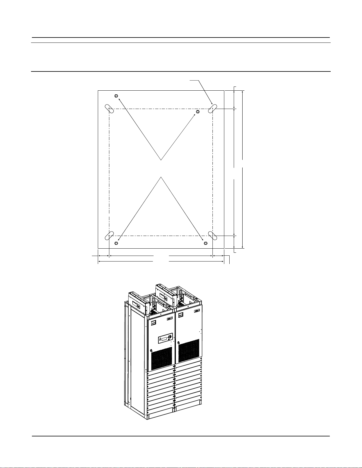
3/8-16 Floor
Leveling Bolts
FRONT
19.62
24.00
2.19
2.19
24.12
30.00
2.44
3.44
0.750 X 2.000 SLOT
(4 PLACES)
Floor Hole Drilling Pattern
Power/Distribution Bay
Spec. No. 582140000 (Models 802NLDB, 802NLEB and 802NL-B) Issue AM, March 26, 2014
Floor Mounting Hole Dimensions Primary and Secondary Power/Distribution Bays without PDSC
(Power Only Bays Have the Same Hole Pattern)
(all dimensions in inches)
This document is property of Emerson Network Power, Energy Systems, North America, Inc. and contains confidential and proprietary information owned by Emerson Network Power, Energy
Systems, North America, Inc. Any copying, use, or disclosure of it without the written permission of Emerson Network Power, Energy Systems, North America, Inc. is strictly prohibited.
Page 3
Page 6
Section 5957 Installation Guide
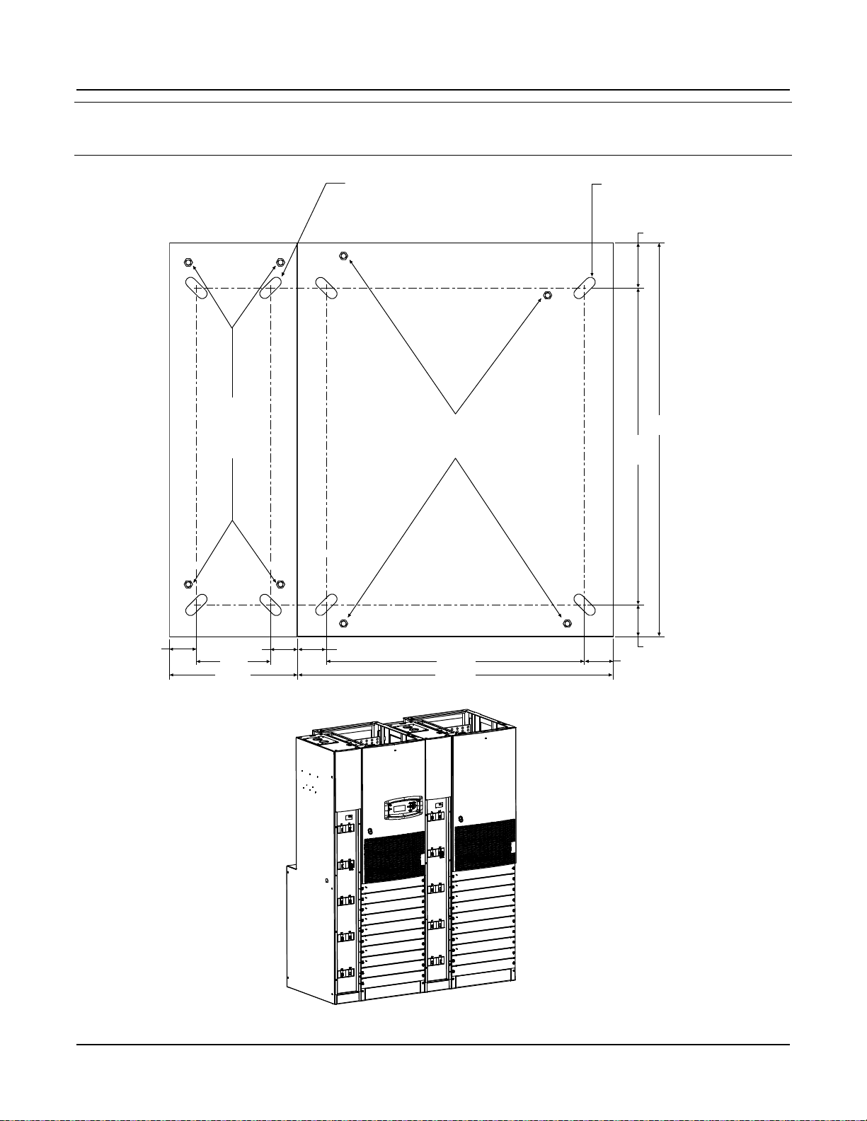
3/8-16 Floor
Leveling Bolts
FRONT
19.62
24.00
2.19
24.12
30.00
2.44
3.44
0.750 X 2.000 SLOT
(4 PLACES)
2.19
9.85
5.63
2.11
2.11
POWER/
DISTRIBUTION BAY
AC POWER
DISTRIBUTION
SERVICE CABINET
0.750 X 2.000 SLOT
(4 PLACES)
3/8-16
Floor
Leveling
Bolts
Floor Hole Drilling Pattern
Power/Distribution Bay
and PDSC
Issue AM, March 26, 2014 Spec. No. 582140000 (Models 802NLDB, 802NLEB and 802NL-B)
Floor Mounting Hole Dimensions Primary and Secondary Power/Distribution Bays with PDSC
(all dimensions in inches)
Page 4
This document is property of Emerson Network Power, Energy Systems, North America, Inc. and contains confidential and proprietary information owned by Emerson Network Power, Energy
Systems, North America, Inc. Any copying, use, or disclosure of it without the written permission of Emerson Network Power, Energy Systems, North America, Inc. is strictly prohibited.
Page 7
Installation Guide Section 5957
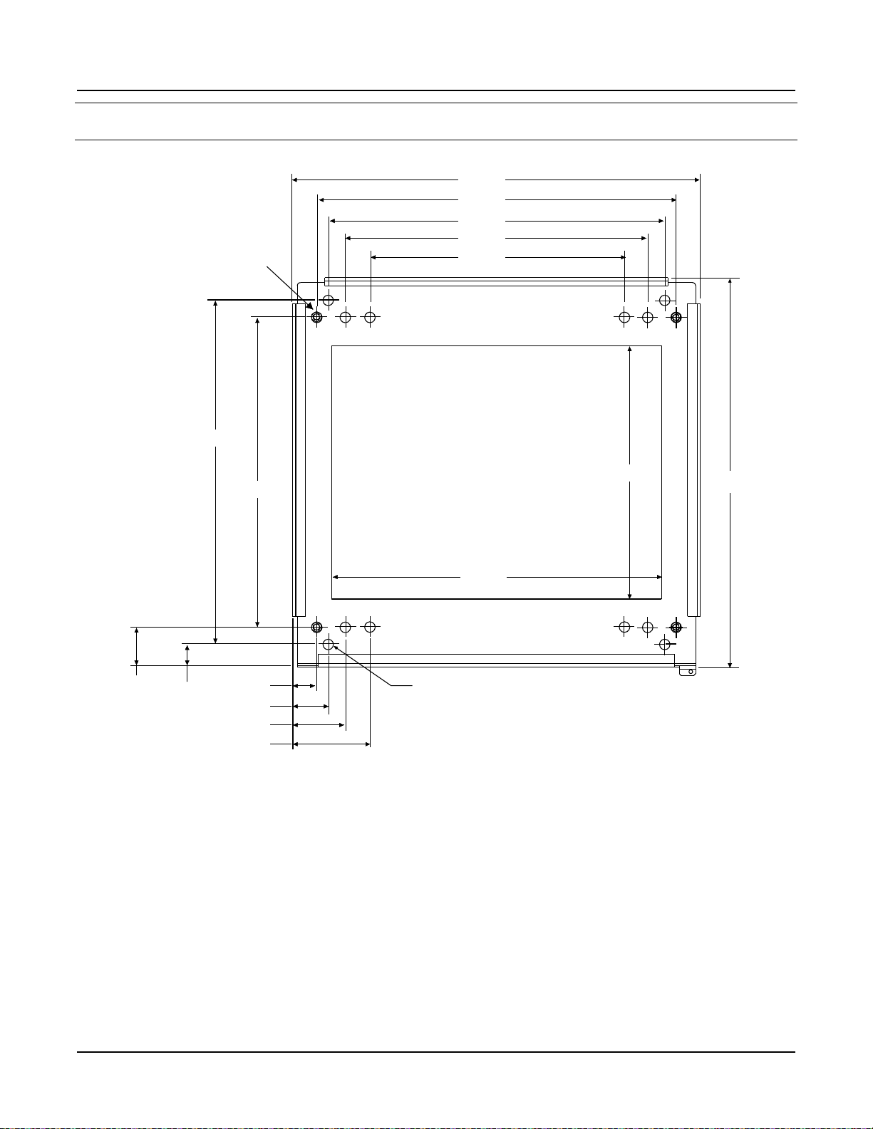
Front
3/8-16
Welded Nut (4)
0.812 Dia.
(8 PLACES)
25.875
23.250
27.625
25.375
19.500
26.625
24.000
3.063
1.750
1.875
2.750
4.063
30.000
31.375
19.500
5.937
Spec. No. 582140000 (Models 802NLDB, 802NLEB and 802NL-B) Issue AM, March 26, 2014
Floor Mounting Hole Dimensions Distribution Only Bay (all dimensions in inches)
This document is property of Emerson Network Power, Energy Systems, North America, Inc. and contains confidential and proprietary information owned by Emerson Network Power, Energy
Systems, North America, Inc. Any copying, use, or disclosure of it without the written permission of Emerson Network Power, Energy Systems, North America, Inc. is strictly prohibited.
Page 5
Page 8
Section 5957 Installation Guide
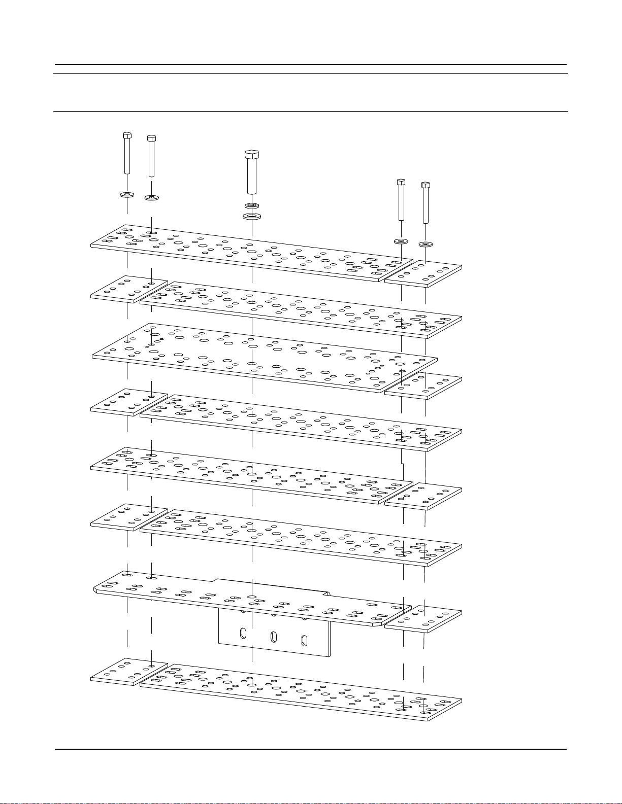
Hardware Build-Up: (use ground washers
in center tie points each side)
Bolt, Ground Washer,Bay/Cabinet Sides,
Ground Washer, Nut
Hardware Build-Up: (use in remaining connection points)
Bolt, Lock Washer, Flat Washer, Bay/Cabinet Sides,
Flat Washer, Lock Washer, Nut
Bay/Cabinet Sides Bay/Cabinet Sides
Holes for Bolting
Power/Distribution
Bays and PDSCs
Togethrer
Issue AM, March 26, 2014 Spec. No. 582140000 (Models 802NLDB, 802NLEB and 802NL-B)
Bolting Power/Distribution Bay to PDSC Cabinet
Page 6
This document is property of Emerson Network Power, Energy Systems, North America, Inc. and contains confidential and proprietary information owned by Emerson Network Power, Energy
Systems, North America, Inc. Any copying, use, or disclosure of it without the written permission of Emerson Network Power, Energy Systems, North America, Inc. is strictly prohibited.
Page 9
Installation Guide Section 5957
Hardware Build-Up: (use ground washers
in center tie points each side)
Bolt, Ground Washer, Bay/Cabinet Sides,
Ground Washer, Nut
Hardware Build-Up: (use in remaining connection points)
Bolt, Lock Washer,Flat Washer, Bay/Cabinet Sides,
Flat Washer,Lock Washer, Nut
Bay/Bay Sides Bay/Bay Sides
Holes for Bolting
Power/Distribution
Bays Togethrer
Spec. No. 582140000 (Models 802NLDB, 802NLEB and 802NL-B) Issue AM, March 26, 2014
Bolting Power/Distribution Bay to Power/Distribution Bay
This document is property of Emerson Network Power, Energy Systems, North America, Inc. and contains confidential and proprietary information owned by Emerson Network Power, Energy
Systems, North America, Inc. Any copying, use, or disclosure of it without the written permission of Emerson Network Power, Energy Systems, North America, Inc. is strictly prohibited.
Page 7
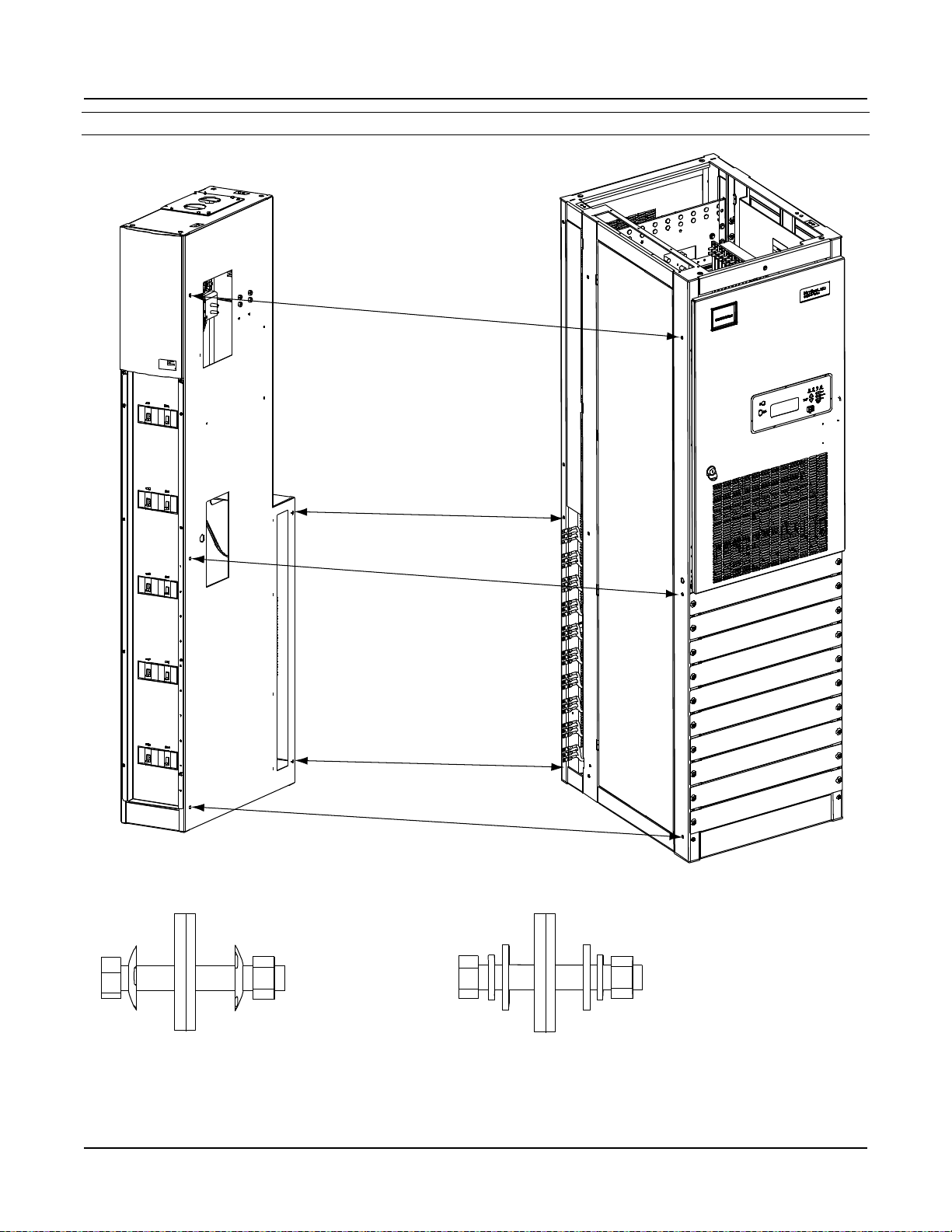
Page 10
Section 5957 Installation Guide
3/8-16 x 1-1/2" Bolt
3/8" Belleville Lock Washer
3/8" Belleville Lock Washer
(concave side of Belleville
Lock Washers face each other)
3/8” Hardened Flat Washer
(10 Places per Busbar)
POSITIVE
BUSBAR LINK
NEGATIVE
BUSBAR LINK
Slide Busbar Links Under
Bays' Upright Channels.
Use Bolt Holes as Shown
in Illustration.
Torque to 180 in-lbs.
Issue AM, March 26, 2014 Spec. No. 582140000 (Models 802NLDB, 802NLEB and 802NL-B)
Installing Power/Distribution Bay to Power/Distribution Bay
Negative and Positive Busbar Links (WITHOUT PDSC)
Page 8
This document is property of Emerson Network Power, Energy Systems, North America, Inc. and contains confidential and proprietary information owned by Emerson Network Power, Energy
Systems, North America, Inc. Any copying, use, or disclosure of it without the written permission of Emerson Network Power, Energy Systems, North America, Inc. is strictly prohibited.
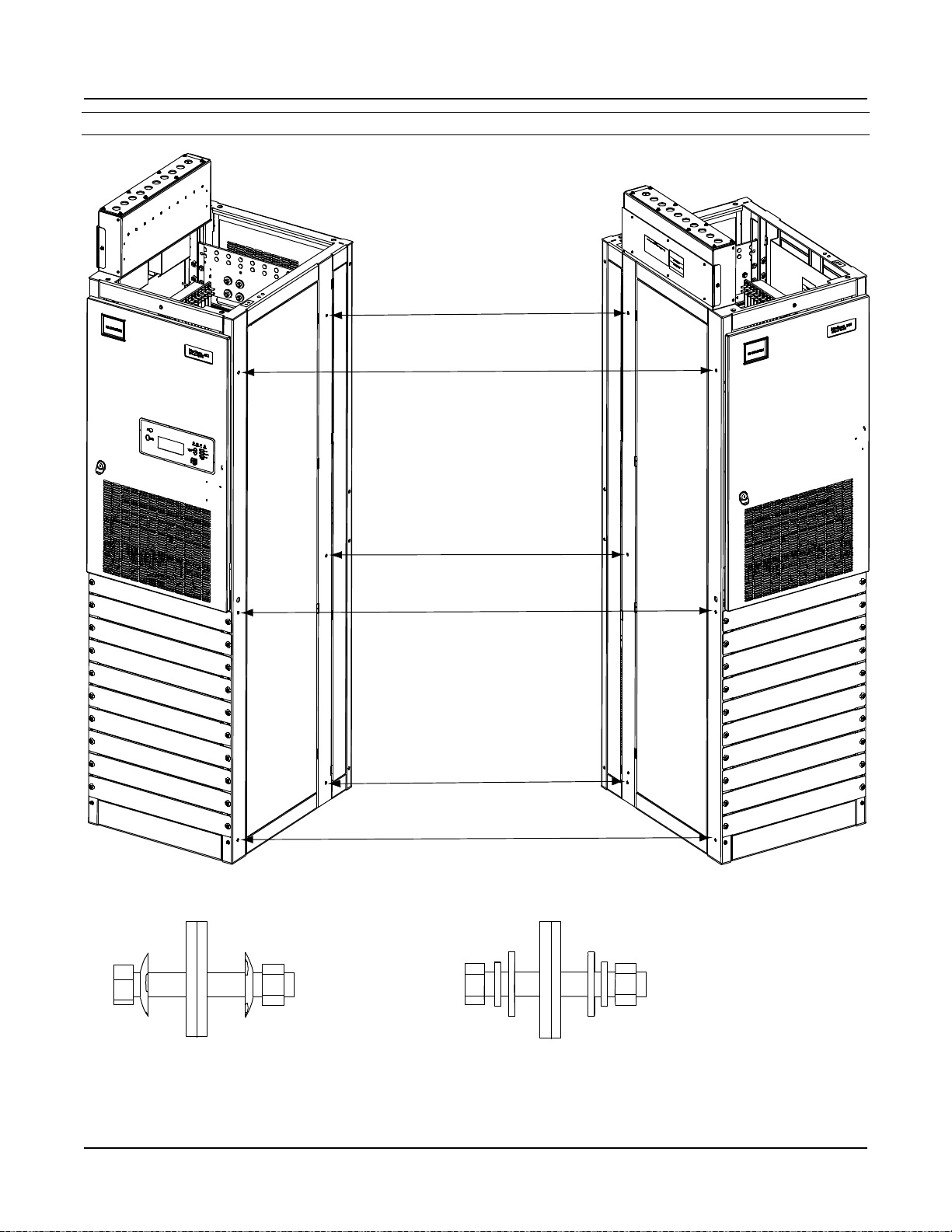
Page 11
Installation Guide Section 5957
Busbar Link
Cover Shield
(installed after
all mounting
and electrical
connection
procedures
are completed)
Slide Busbar Links Under
Bays' Upright Channels.
Use Bolt Holes as Shown
in Illustration.
Torque to 180 in-lbs.
3/8-16 x 1-1/2" Bolt
3/8" Belleville Lock Washer
3/8" Belleville Lock Washer
(concave side of Belleville
Lock Washers face each other)
3/8” Hardened Flat Washer
(10 Places per Busbar)
POSITIVE
BUSBAR LINK
NEGATIVE
BUSBAR LINK
Spec. No. 582140000 (Models 802NLDB, 802NLEB and 802NL-B) Issue AM, March 26, 2014
Installing Power/Distribution Bay to Power/Distribution Bay
Negative and Positive Busbar Links (WITH PDSC)
This document is property of Emerson Network Power, Energy Systems, North America, Inc. and contains confidential and proprietary information owned by Emerson Network Power, Energy
Systems, North America, Inc. Any copying, use, or disclosure of it without the written permission of Emerson Network Power, Energy Systems, North America, Inc. is strictly prohibited.
Page 9
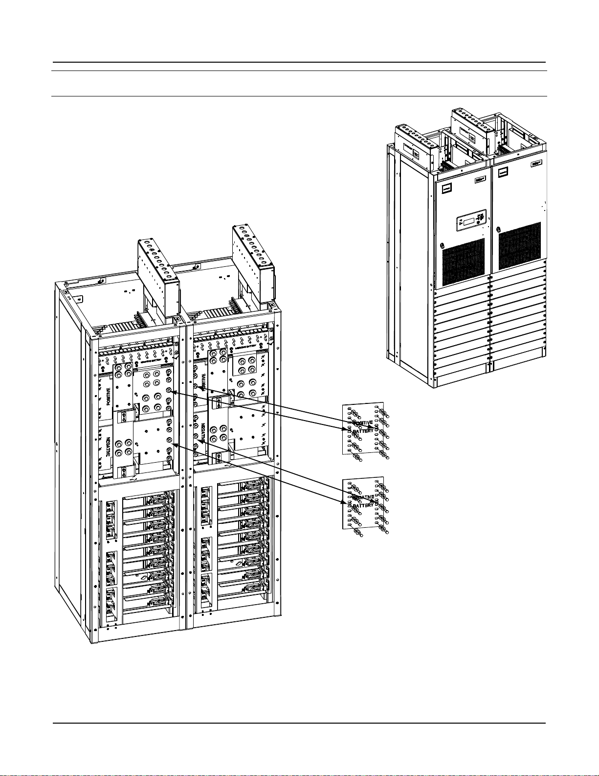
Page 12
Section 5957 Installation Guide
3/8-16 x 1-1/2" Bolt
3/8" Belleville Lock Washer
3/8" Belleville Lock Washer
(concave side of Belleville
Lock Washers face each other)
3/8” Hardened Flat Washer
POSITIVE
BUSBAR LINK
NEGATIVE
BUSBAR LINK
Existing Older Style Bay
side, use ALL bolt holes.
Slide Busbar Links Under
Bays' Upright Channels.
Torque to 180 in-lbs.
Newer Style Bay side,
use bolt holes as
shown in illustration.
Existing Older
Style Bay
Existing Older
Style Bay
Newer
Style Bay
Newer
Style Bay
List 1 and 11 shown.
List 2 and 12 w/ List 30 or 31 similar.
Issue AM, March 26, 2014 Spec. No. 582140000 (Models 802NLDB, 802NLEB and 802NL-B)
Installing Power/Distribution Bay to Power/Distribution Bay
Negative and Positive Busbar Links – New Style Bay Connected to an Existing Older Style Bay
Page 10
This document is property of Emerson Network Power, Energy Systems, North America, Inc. and contains confidential and proprietary information owned by Emerson Network Power, Energy
Systems, North America, Inc. Any copying, use, or disclosure of it without the written permission of Emerson Network Power, Energy Systems, North America, Inc. is strictly prohibited.
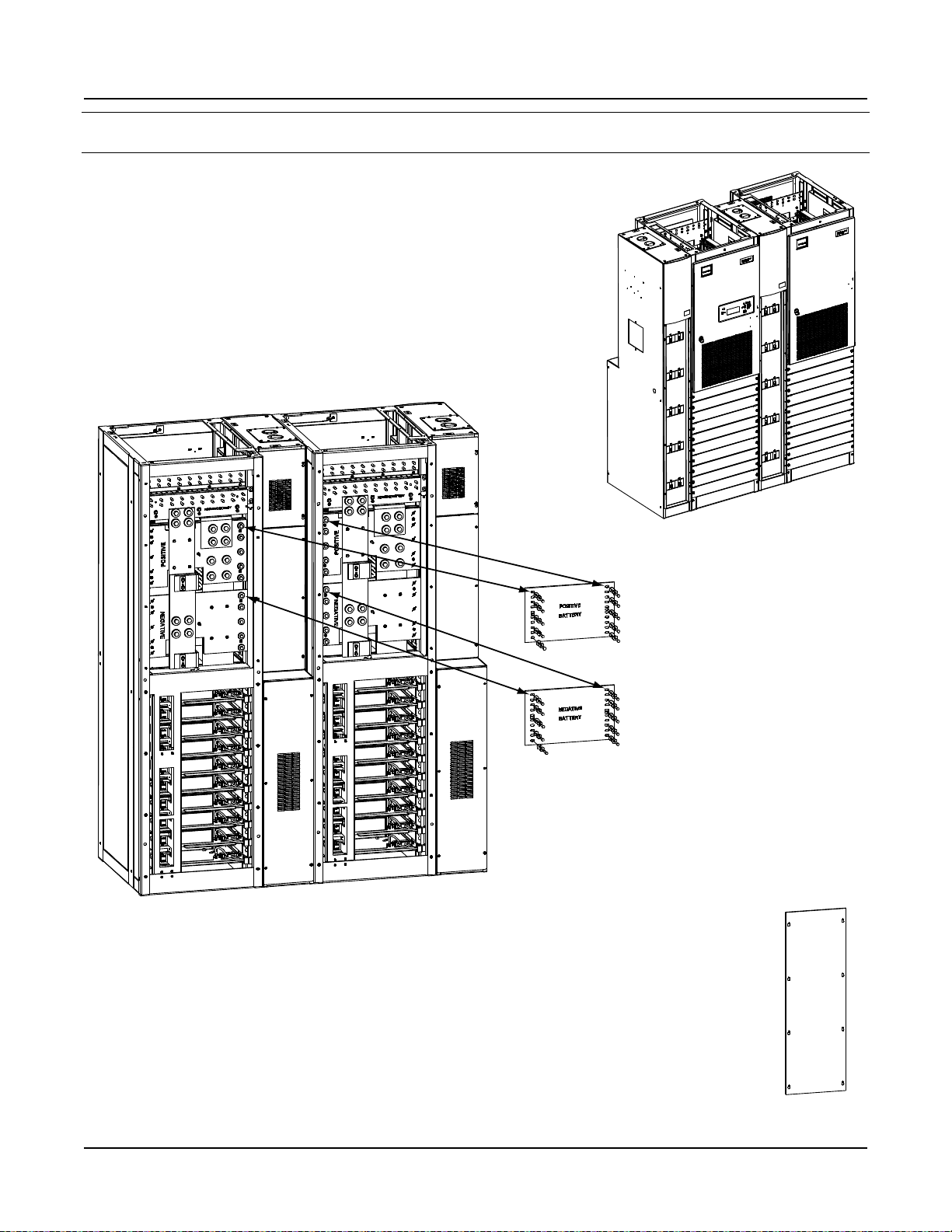
Page 13
Installation Guide Section 5957
Power/Distribution
Bay
Power/Distribution
Bay
PDSC
PDSC
Row of PDSC PCU
AC Input Connectors
Connectors
in PDSC
to
PCU Mtg.
Pos. #1
to
PCU Mtg.
Pos. #2
to
PCU Mtg.
Pos. #3
to
PCU Mtg.
Pos. #4
to
PCU Mtg.
Pos. #5
to
PCU Mtg.
Pos. #6
to
PCU Mtg.
Pos. #7
to
PCU Mtg.
Pos. #8
to
PCU Mtg.
Pos. #9
to
PCU Mtg.
Pos. #10
Torque to
23 in-lbs.
A
B
C
A
B
C
A
B
C
A
B
C
A
B
C
A
B
C
A
B
C
A
B
C
A
B
C
A
B
C
Row of PCU Mtg. Pos.
AC Input Connectors
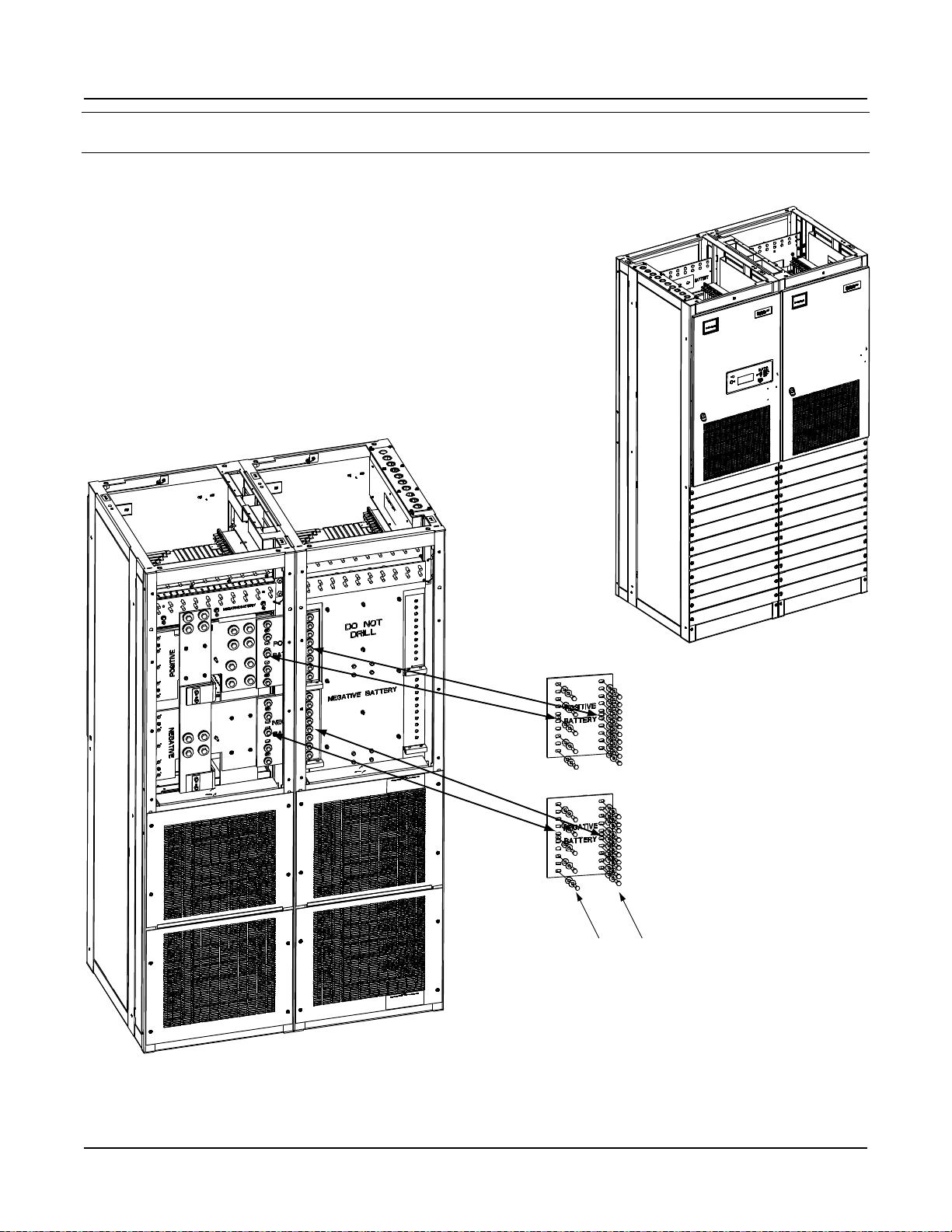
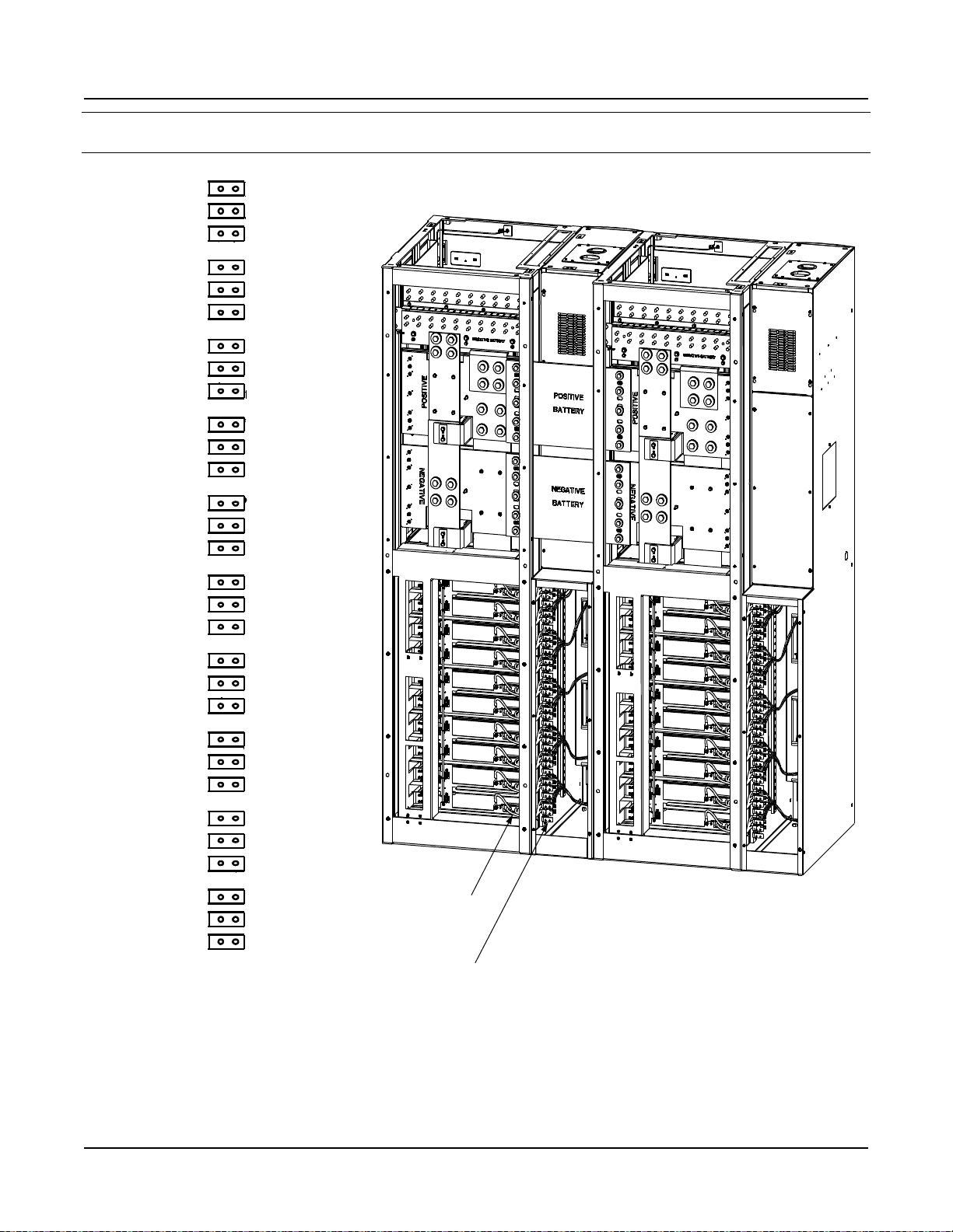
Spec. No. 582140000 (Models 802NLDB, 802NLEB and 802NL-B) Issue AM, March 26, 2014
Connecting Rectifier Mounting Position AC Input Connectors to PDSC
(Lists 2 and 12 Only)
This document is property of Emerson Network Power, Energy Systems, North America, Inc. and contains confidential and proprietary information owned by Emerson Network Power, Energy
Systems, North America, Inc. Any copying, use, or disclosure of it without the written permission of Emerson Network Power, Energy Systems, North America, Inc. is strictly prohibited.
Page 11
Page 14
Section 5957 Installation Guide
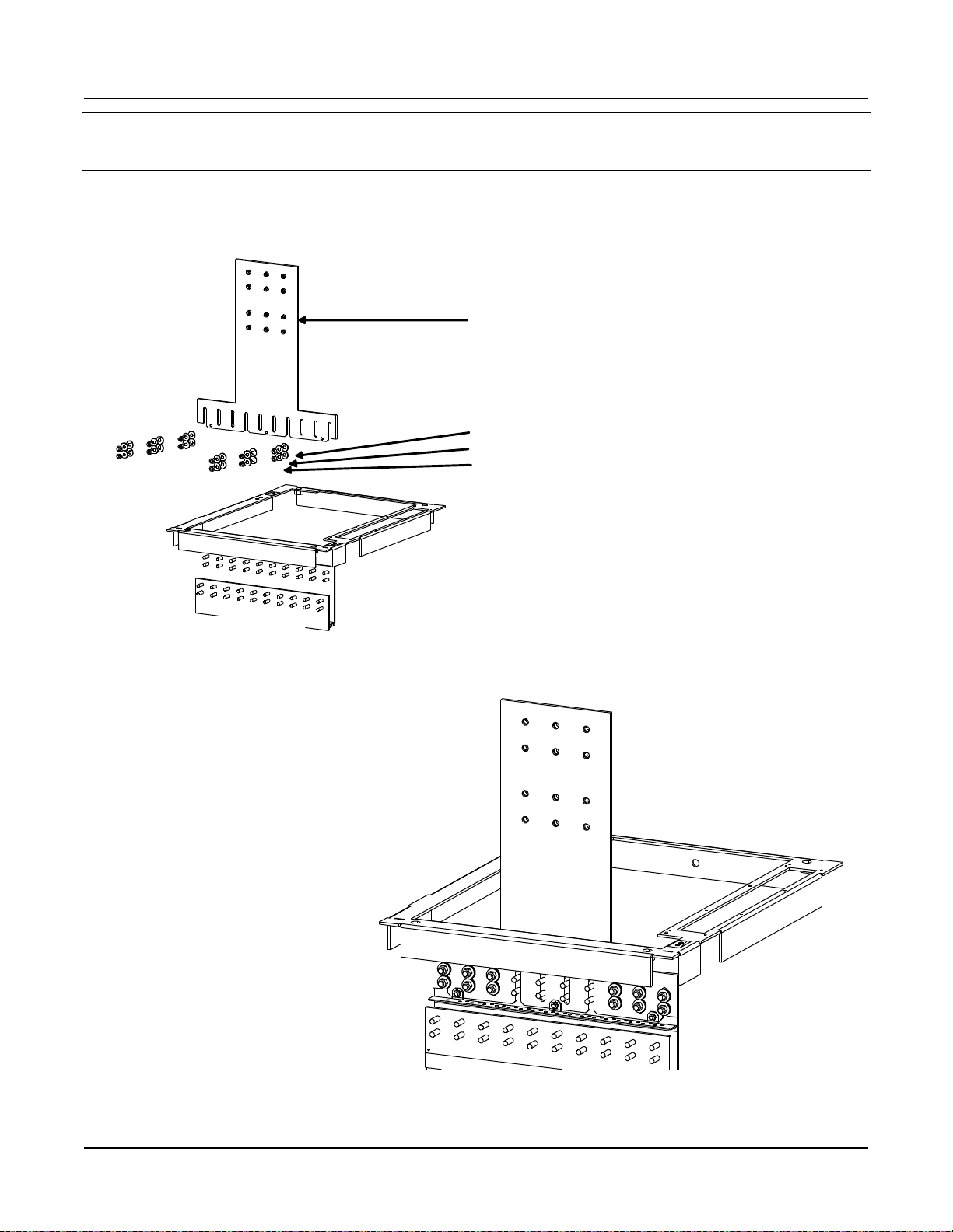
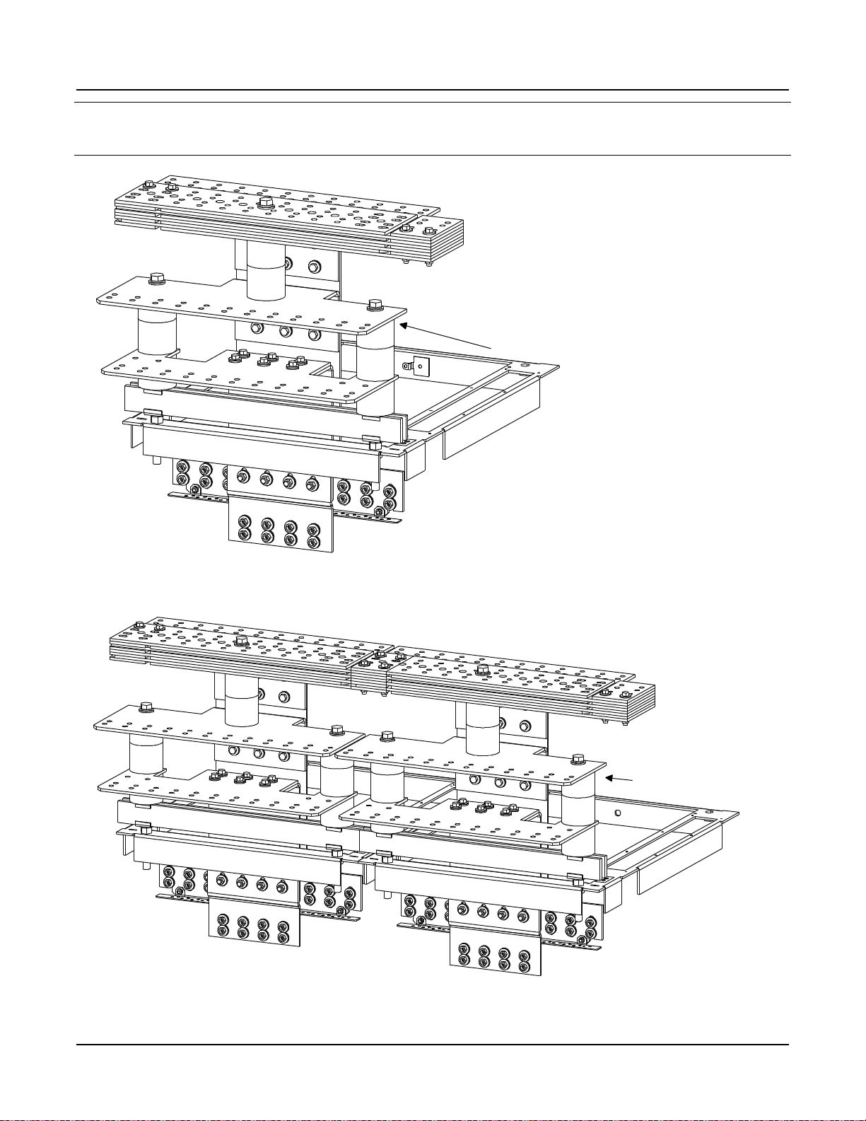
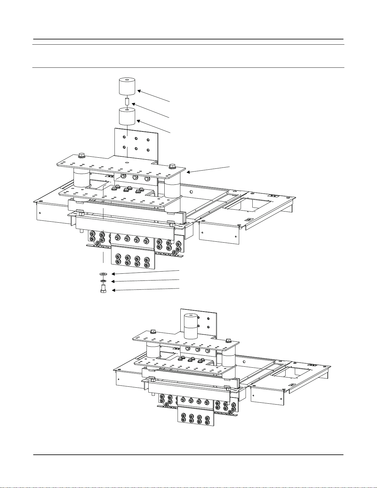
STEP 1
Install “Main Positive Busbar” onto Bay’s
Positive Busbar.Hand-tighten hardware.
(1) Main Positive Busbar, P/N 554877
Note:Apply Electrical Anti-Oxidation Compound
to Busbar Mating Surfaces.
(12) 3/8” Flat Washer, P/N 214204100
(12) 3/8” Belleville Washer, P/N 214825000
(12) 3/8-16 Hex Nut, P/N 228567100
Hand-tighten.
Note: Concave Side of Belleville Washer Faces
Busbar, Convex Side Faces Hex Nut.
Belleville Washer install between Hex Nut
and Flat Washer.
Rear Top
of Bay
Assembled
View
Do the following first before assembly:
1. Remove 552402 (1) and 116638 (4) from Bay.
2. Mount 554880 to the 554877 with 116638 (3).
Issue AM, March 26, 2014 Spec. No. 582140000 (Models 802NLDB, 802NLEB and 802NL-B)
Power/Distribution Bay
External Top-Mount Horizontal Battery Input Busbar Assembly (P/N 554873)
Assembly Procedure Step 1
Page 12
This document is property of Emerson Network Power, Energy Systems, North America, Inc. and contains confidential and proprietary information owned by Emerson Network Power, Energy
Systems, North America, Inc. Any copying, use, or disclosure of it without the written permission of Emerson Network Power, Energy Systems, North America, Inc. is strictly prohibited.
Page 15
Installation Guide Section 5957
Assembled
View
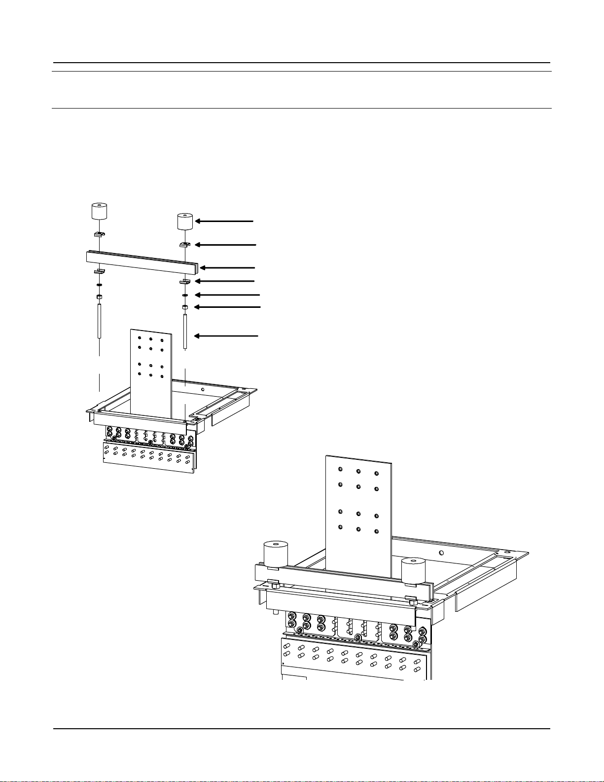
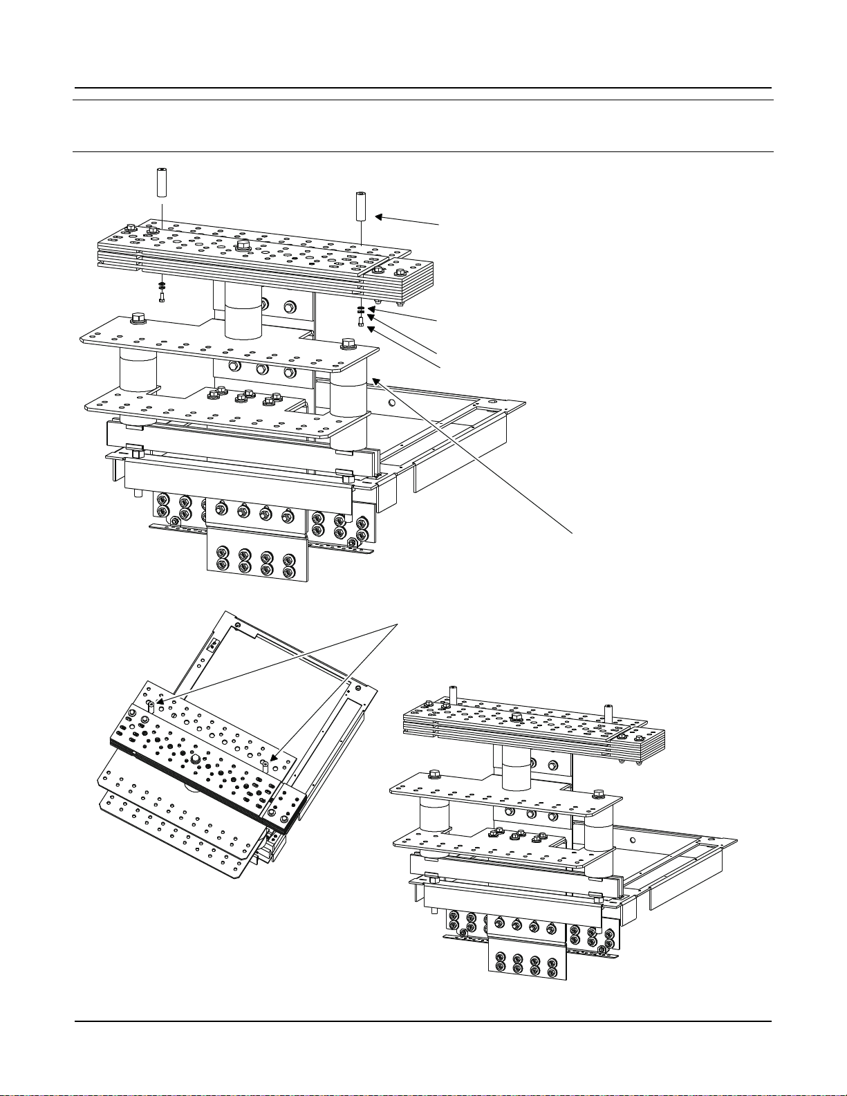
STEP 2
Install “Support Bar” and “Related
Hardware” onto Top of Bay.
(2) Threaded Insulator, P/N 245857200 Torque to 715 In-lbs.
(2) Support Bar Clip, P/N 351322300
(2) Support Bar, P/N 237790100
(2) 5/8” Lock Washer, P/N 215111800
(2) 5/8” Hex Nut, P/N 228580900 Leave 1/4” Space Between
Bottom of Nut and Top of Bay.
(2) 5/8-11 x 7” Threaded Rod, P/N 334317000
(2) Support Bar Clip, P/N 351322300
Rear Top
of Bay
Spec. No. 582140000 (Models 802NLDB, 802NLEB and 802NL-B) Issue AM, March 26, 2014
Power/Distribution Bay
External Top-Mount Horizontal Battery Input Busbar Assembly (P/N 554873)
Assembly Procedure Step 2
This document is property of Emerson Network Power, Energy Systems, North America, Inc. and contains confidential and proprietary information owned by Emerson Network Power, Energy
Systems, North America, Inc. Any copying, use, or disclosure of it without the written permission of Emerson Network Power, Energy Systems, North America, Inc. is strictly prohibited.
Page 13
Page 16
Section 5957 Installation Guide
Assembled
View
STEP 3
Install “Main Negative Busbar” onto Bay’s
Negative Busbar. Hand-tighten hardware.
(1) Main Negative Busbar, P/N 554875
Rear Top
of Bay
Note: Apply Electrical Anti-Oxidation Compound
to Busbar Mating Surfaces.
(8) 3/8” Flat Washer, P/N 214204100
(8) 3/8” Belleville Washer, P/N 214825000
(8) 3/8-16 Hex Nut, P/N 228567100 Hand-Tighten
Note: Concave Side of Belleville Washer Faces
Busbar,Convex Side Faces Hex Nut.
Belleville Washer Install between Hext Nut
and Flat Washer.
Mount 554876 to the 554875.
Hardware:
214204100 (4)
214825000 (4)
228567100 (4)
Issue AM, March 26, 2014 Spec. No. 582140000 (Models 802NLDB, 802NLEB and 802NL-B)
Power/Distribution Bay
External Top-Mount Horizontal Battery Input Busbar Assembly (P/N 554873)
Assembly Procedure Step 3
Page 14
This document is property of Emerson Network Power, Energy Systems, North America, Inc. and contains confidential and proprietary information owned by Emerson Network Power, Energy
Systems, North America, Inc. Any copying, use, or disclosure of it without the written permission of Emerson Network Power, Energy Systems, North America, Inc. is strictly prohibited.
Page 17
Installation Guide Section 5957
Note: Concave Side of Belleville Washer Faces
Busbar, Convex Side Faces Bolt Head.
Belleville Washer install between Bolt Head
and Flat Washer.
(1) Horizontal Landing Negative Busbar, P/N 514434
Note: Apply Electrical Anti-Oxidation Compound
to Busbar Mating Surfaces.
(6) 3/8” Belleville Washer, P/N 214825000
(6) 3/8-16 x 1-1/4” Bolt, P/N 227646800
(6) 3/8" Flat Washer, P/N 214204100
Assembled
View
Rear Top
of Bay
STEP 4
Install “Horizontal Landing Negative Busbar”
onto “Main Negative Busbar”.
Torque to 180 in-lbs.
Spec. No. 582140000 (Models 802NLDB, 802NLEB and 802NL-B) Issue AM, March 26, 2014
Power/Distribution Bay
External Top-Mount Horizontal Battery Input Busbar Assembly (P/N 554873)
Assembly Procedure Step 4
This document is property of Emerson Network Power, Energy Systems, North America, Inc. and contains confidential and proprietary information owned by Emerson Network Power, Energy
Systems, North America, Inc. Any copying, use, or disclosure of it without the written permission of Emerson Network Power, Energy Systems, North America, Inc. is strictly prohibited.
Page 15
Page 18
Section 5957 Installation Guide
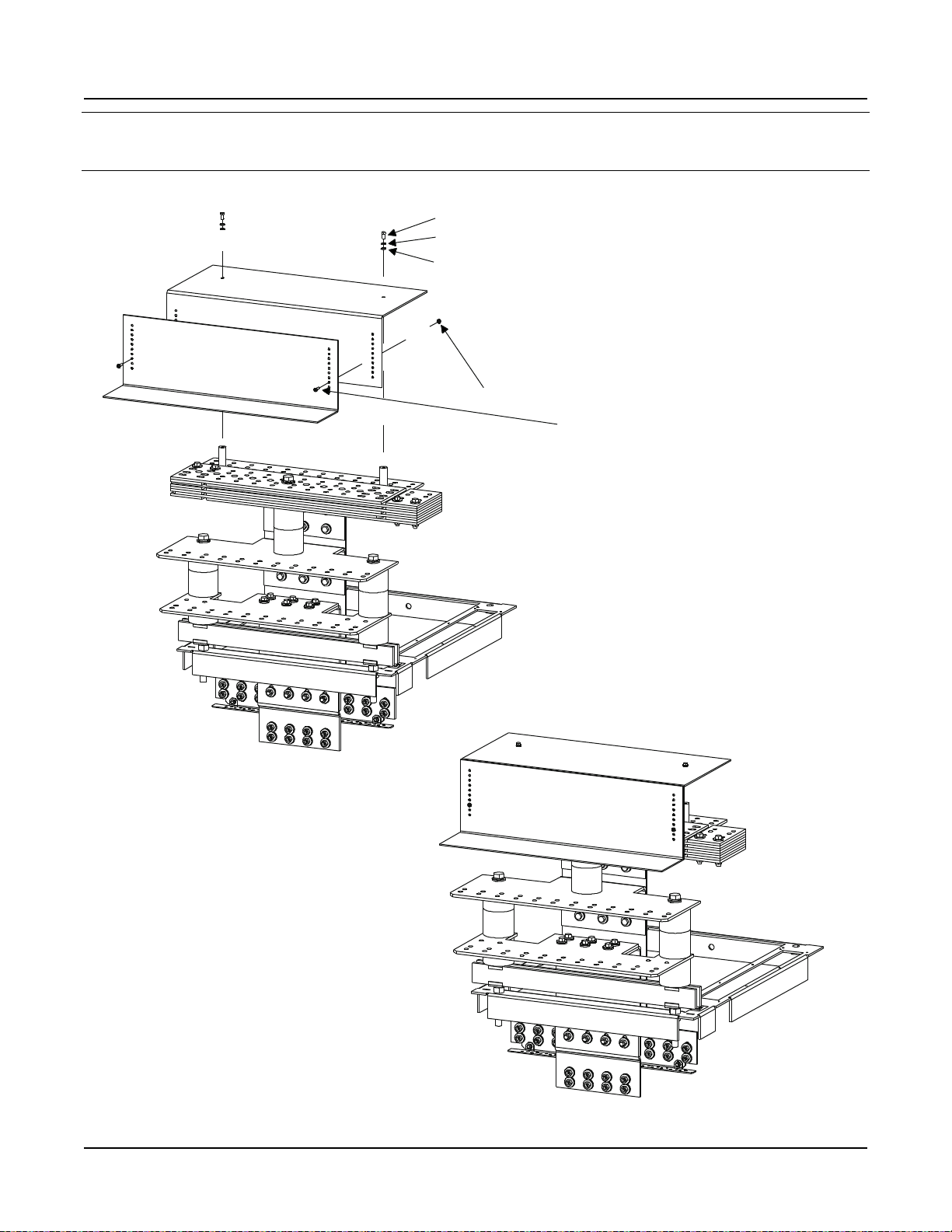
STEP 5
Install "Threaded Insulators" onto
"Horizontal Landing Negative Busbar".
(2) Threaded Insulator,P/N 245857200
(2) 5/8-11 x 1-1/4" Threaded Rod, P/N 334315700
(2) Threaded Insulator,P/N 245857200
(2) 5/8-11 x 1-1/2" Threaded Rod, P/N 334315900
Hand-Tighten
Hand-Tighten
Assembled
View
Rear Top
of Bay
Issue AM, March 26, 2014 Spec. No. 582140000 (Models 802NLDB, 802NLEB and 802NL-B)
Power/Distribution Bay
External Top-Mount Horizontal Battery Input Busbar Assembly (P/N 554873)
Assembly Procedure Step 5
Page 16
This document is property of Emerson Network Power, Energy Systems, North America, Inc. and contains confidential and proprietary information owned by Emerson Network Power, Energy
Systems, North America, Inc. Any copying, use, or disclosure of it without the written permission of Emerson Network Power, Energy Systems, North America, Inc. is strictly prohibited.
Page 19
Installation Guide Section 5957
STEP 6
Install "Horizontal Landing Positive Busbar"
onto "Main Positive Busbar".
(2) 5/8-11 x 1" Bolt, P/N 227655100
(2) 5/8" Lock Washer, P/N 215111800
(2) 5/8" Flat Washer, P/N 214201300
Torque to 715 in-lbs.
(1) Horizontal Landing Positive Busbar, P/N 514436
Note: Apply Electrical Anti-Oxidation Compound
to Busbar Mating Surfaces.
(6) 3/8" Flat Washer, P/N 214204100
(6) 3/8" Belleville Washer, P/N 214825000
(6) 3/8-16 x 1-1/4" Bolt, P/N 227646800
Torque to 180 in-lbs.
Note: Concave Side of Belleville Washer Faces
Busbar, Convex Side Faces Bolt Head.
Belleville Washer install between Bolt Head
and Flat Washer.
Assembled
View
Rear Top
of Bay
Spec. No. 582140000 (Models 802NLDB, 802NLEB and 802NL-B) Issue AM, March 26, 2014
Power/Distribution Bay
External Top-Mount Horizontal Battery Input Busbar Assembly (P/N 554873)
Assembly Procedure Step 6
This document is property of Emerson Network Power, Energy Systems, North America, Inc. and contains confidential and proprietary information owned by Emerson Network Power, Energy
Systems, North America, Inc. Any copying, use, or disclosure of it without the written permission of Emerson Network Power, Energy Systems, North America, Inc. is strictly prohibited.
Page 17
Page 20
Section 5957 Installation Guide
Torque these connections
to 180 in-lbs (20 places).
Rear Top
of Bay
STEP 7
Final Torque
Issue AM, March 26, 2014 Spec. No. 582140000 (Models 802NLDB, 802NLEB and 802NL-B)
Power/Distribution Bay
External Top-Mount Horizontal Battery Input Busbar Assembly (P/N 554873)
Assembly Procedure Step 7
Page 18
This document is property of Emerson Network Power, Energy Systems, North America, Inc. and contains confidential and proprietary information owned by Emerson Network Power, Energy
Systems, North America, Inc. Any copying, use, or disclosure of it without the written permission of Emerson Network Power, Energy Systems, North America, Inc. is strictly prohibited.
Page 21
Installation Guide Section 5957
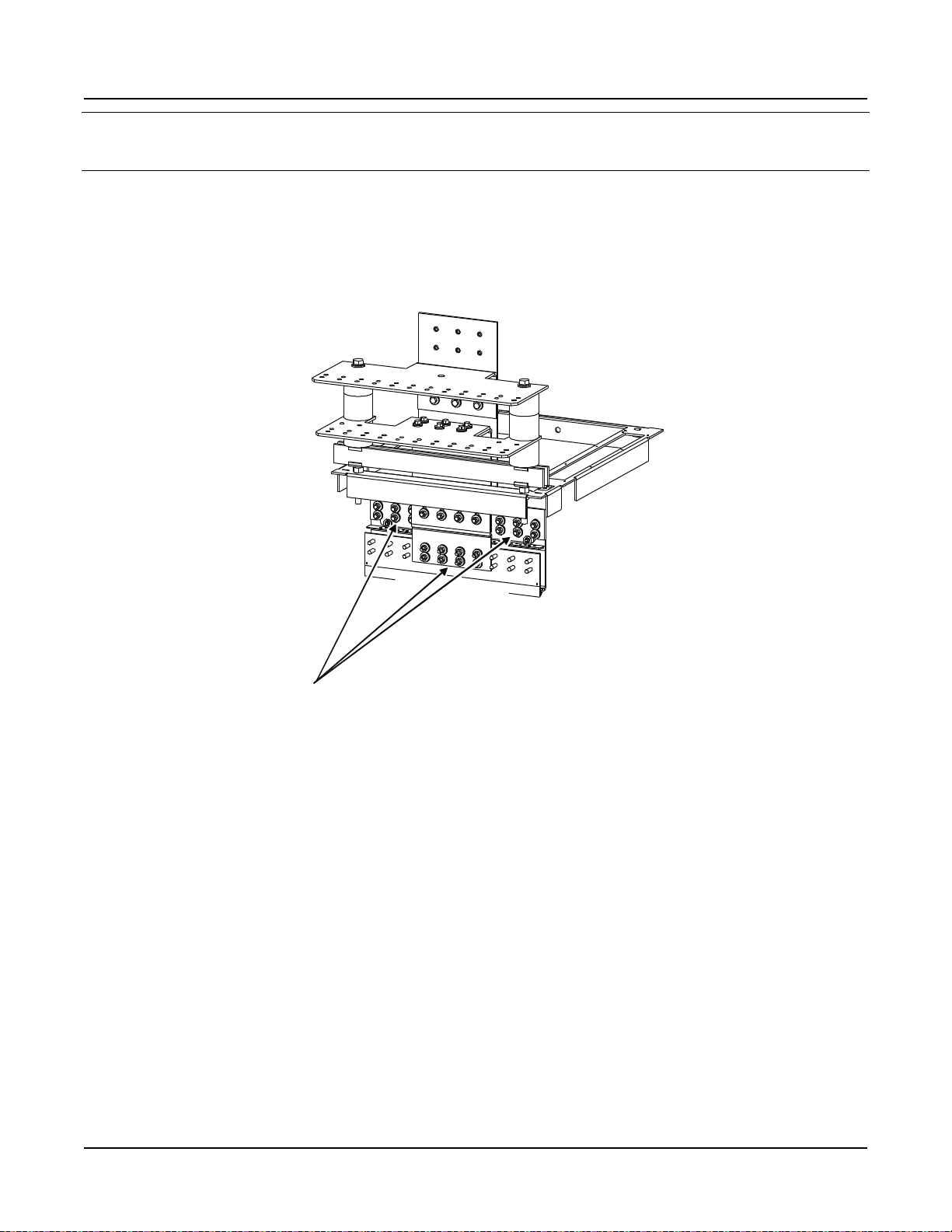
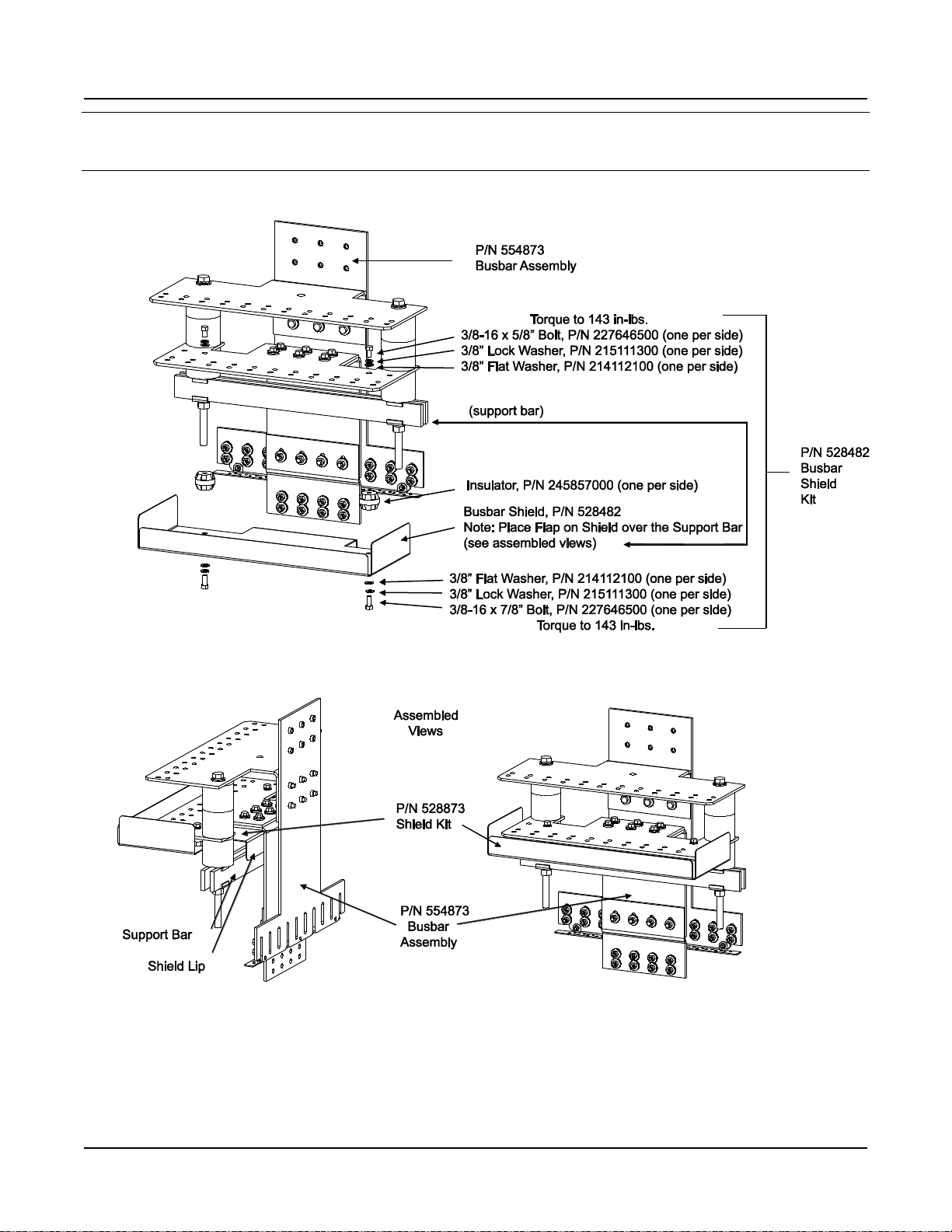
Spec. No. 582140000 (Models 802NLDB, 802NLEB and 802NL-B) Issue AM, March 26, 2014
Power/Distribution Bay
Busbar Shield Kit (P/N 528482)
Assembly Procedure
This document is property of Emerson Network Power, Energy Systems, North America, Inc. and contains confidential and proprietary information owned by Emerson Network Power, Energy
Systems, North America, Inc. Any copying, use, or disclosure of it without the written permission of Emerson Network Power, Energy Systems, North America, Inc. is strictly prohibited.
Page 19
Page 22
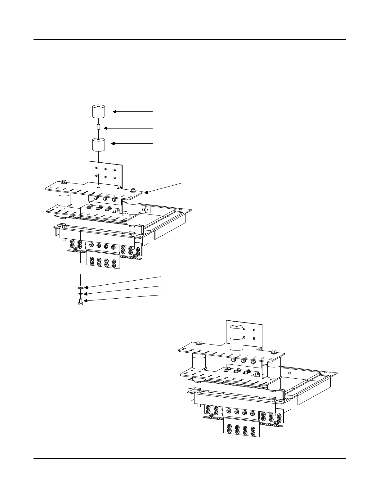
Section 5957 Installation Guide
STEP 1
Install "Threaded Insulators".
(1) Threaded Insulator, P/N 245857200
(1) 5/8-11 x 1-1/4" Threaded Rod, P/N 334315700
(1) Threaded Insulator, P/N 245857200
PreviouslyAssembled
Kit P/N 554873
(1) 5/8" Flat Washer, P/N 214201300
(1) 5/8" Lock Washer, P/N 215111800
(1) 5/8-11 x 1" Bolt, P/N 227655100
Hand-Tighten
Torque to 715 in-lbs.
Assembled
View
Rear
Top
of Bay
Issue AM, March 26, 2014 Spec. No. 582140000 (Models 802NLDB, 802NLEB and 802NL-B)
Power/Distribution Bay
External Top-Mount Ground (Load Return) Busbar Assembly (P/N 514688 or 514689)
Assembly Procedure Step 1
Page 20
This document is property of Emerson Network Power, Energy Systems, North America, Inc. and contains confidential and proprietary information owned by Emerson Network Power, Energy
Systems, North America, Inc. Any copying, use, or disclosure of it without the written permission of Emerson Network Power, Energy Systems, North America, Inc. is strictly prohibited.
Page 23
Installation Guide Section 5957
P/N214204100
(6)3/8" FlatWasher
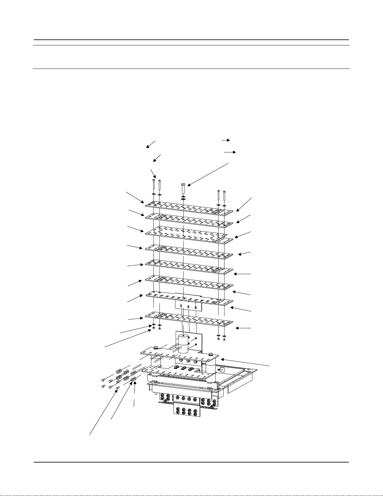
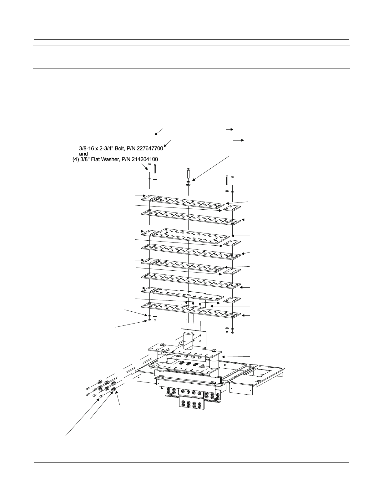
STEP 2A
Install "Busbars".
(see Step 2B for Bolt Hole Identification)
(see Step 2C for Assembled View)
Note: Apply ElectricalAnti-Oxidation
Compound to all Busbar
Mating Surfaces.
* Use "Spacer Busbars" or "Spacer Insulators"
Busbar Assy P/N 514688
Busbar Assy P/N 514689
(1)5/8-11x 1-3/4" Bolt,P/N 227653800
or Torque to 715 in-lbs.
5/8-11 x 2-3/4" Bolt,P/N 227653900
and
(1)5/8" LockWasher, P/N215111800
and
(1)5/8" Flat Washer, P/N214201300
Spacer Insulator,P/N514473,
orBusbarfromNext Bay*
P/N 514689 Only
Busbar,P/N514467
Spacer Insulator,P/N514473,
orBusbarfromNext Bay*
Busbar, P/N514467
P/N 514689 Only
Spacer Insulator,P/N514473,
orBusbarfromNext Bay*
P/N 514689 Only
Busbar, P/N514467
SpacerInsulator, P/N514473,
orBusbarfromNext Bay*
Busbar, P/N514467
Note: ConcaveSideofBelleville Washer Faces
Busbar,Convex SideFacesNut.
PreviouslyAssembled
KitP/N554873
Note: ConcaveSideofBelleville
Washer Faces Busbar,
ConvexSideFacesBolt Head.
Belleville Washer install between
Bolt HeadandFlat Washer.
Torque to 180 in-lbs.
P/N227646800
(6)3/8-16x1-1/4"Bolt
P/N214825000
(6)3/8" BellevilleWasher
P/N228567100
(4)3/8-16Hex Nut
P/N214825000
(4)3/8" BellevilleWasher
or BusbarfromNext Bay*
SpacerBusbar,P/N514472,
Busbar, P/N514541
orBusbarfrom Next Bay*
Spacer Busbar, P/N 514472,
P/N 514689 Only
Busbar, P/N514467
P/N 514689 Only
orBusbarfrom Next Bay*
Spacer Busbar, P/N 514472,
orBusbarfrom Next Bay*
Spacer Busbar, P/N 514472,
Busbar, P/N514522
P/N 514689 Only
Busbar, P/N514467
(4)3/8" FlatWasher, P/N214204100
and
3/8-16x 2-3/4" Bolt,P/N 227647700
or
(4)3/8-16x 2" Bolt,P/N 227647400
Torque to 180 in-lbs.
on end bays or stand-alone bays. For multiple
bays, 'sandwich' busbars of adjacent "Busbar
Assemblies" together.
Rear Top
of Bay
Spec. No. 582140000 (Models 802NLDB, 802NLEB and 802NL-B) Issue AM, March 26, 2014
Power/Distribution Bay
External Top-Mount Ground (Load Return) Busbar Assembly (P/N 514688 or 514689)
Assembly Procedure Step 2A
This document is property of Emerson Network Power, Energy Systems, North America, Inc. and contains confidential and proprietary information owned by Emerson Network Power, Energy
Systems, North America, Inc. Any copying, use, or disclosure of it without the written permission of Emerson Network Power, Energy Systems, North America, Inc. is strictly prohibited.
Page 21
Page 24
Section 5957 Installation Guide
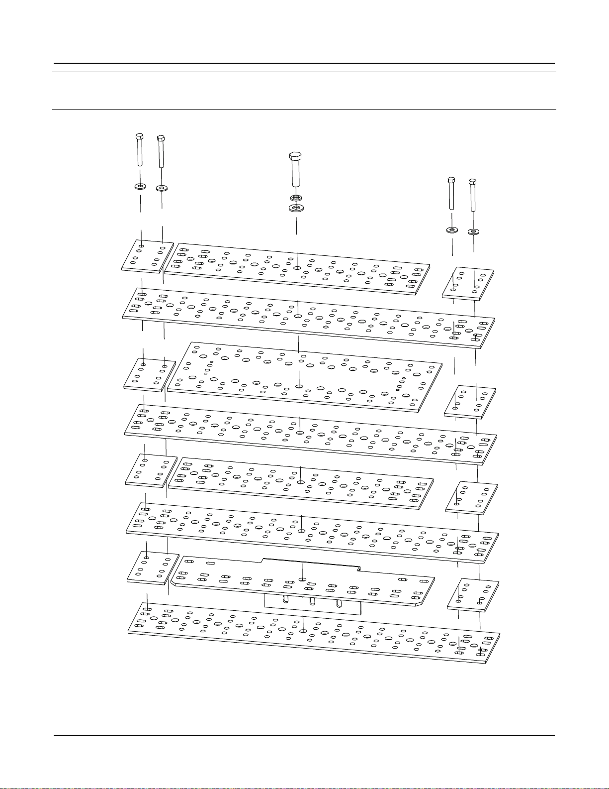
STEP 2B
Install "Busbars".
(Bolt Hole Identification)
Issue AM, March 26, 2014 Spec. No. 582140000 (Models 802NLDB, 802NLEB and 802NL-B)
Power/Distribution Bay
External Top-Mount Ground (Load Return) Busbar Assembly (P/N 514688 or 514689)
Assembly Procedure Step 2B
Page 22
This document is property of Emerson Network Power, Energy Systems, North America, Inc. and contains confidential and proprietary information owned by Emerson Network Power, Energy
Systems, North America, Inc. Any copying, use, or disclosure of it without the written permission of Emerson Network Power, Energy Systems, North America, Inc. is strictly prohibited.
Page 25
Installation Guide Section 5957
STEP 2C
Install "Busbars".
(Assembled Views)
Spacer Busbars
or Spacer Insulators
Installed
Previously Assembled
Kit P/N 554873
Assembled
Views
No Spacer Busbars or Spacer Insulators.
Busbars ofAdjacent Assemblies 'Sandwich'
and Bolted Together.
Previously Assembled
Kit P/N 554873
Spec. No. 582140000 (Models 802NLDB, 802NLEB and 802NL-B) Issue AM, March 26, 2014
Power/Distribution Bay
External Top-Mount Ground (Load Return) Busbar Assembly (P/N 514688 or 514689)
Assembly Procedure Step 2C
This document is property of Emerson Network Power, Energy Systems, North America, Inc. and contains confidential and proprietary information owned by Emerson Network Power, Energy
Systems, North America, Inc. Any copying, use, or disclosure of it without the written permission of Emerson Network Power, Energy Systems, North America, Inc. is strictly prohibited.
Page 23
Page 26
Section 5957 Installation Guide
STEP 3
Install "Cover" Mounting Standoffs.
(2) Standoff, P/N 117843
(2) 1/4" Flat Washer, P/N 214110100
(2) 1/4" Lock Washer, P/N 215111100
(2) 1/4-20 x 1/2" Bolt, P/N 227640200
Torque to 84 in-lbs.
Previously Assembled
Kit P/N 554873
DO NOT PERFORM THIS STEP if you are going to install
"Load Return Lug Extension Busbar Assembly" P/N 514543
Use These Holes
Assembled
View
Rear
Top
of Bay
Issue AM, March 26, 2014 Spec. No. 582140000 (Models 802NLDB, 802NLEB and 802NL-B)
Power/Distribution Bay
External Top-Mount Ground (Load Return) Busbar Assembly (P/N 514688 or 514689)
Assembly Procedure Step 3
Page 24
This document is property of Emerson Network Power, Energy Systems, North America, Inc. and contains confidential and proprietary information owned by Emerson Network Power, Energy
Systems, North America, Inc. Any copying, use, or disclosure of it without the written permission of Emerson Network Power, Energy Systems, North America, Inc. is strictly prohibited.
Page 27
Installation Guide Section 5957
STEP 4
Install "Covers".
(2) 1/4-20 x 1/2" Bolt, P/N 227640200
(2) 1/4" Lock Washer, P/N 215111100
(2) 1/4" Flat Washer, P/N 214110100
Torque to 45 in-lbs.
(2) 10-32 Lock Nut, P/N 104564
(2) 10-32 x 3/4" Tap Screw, P/N 218706500
DO NOT PERFORM THIS STEP if you are going to install
"Load Return Lug Extension Busbar Assembly" P/N 514543
P
/
N
5
1
4
5
2
0
P
/
N
5
1
4
5
2
1
Assembled
View
Rear
Top
of Bay
Spec. No. 582140000 (Models 802NLDB, 802NLEB and 802NL-B) Issue AM, March 26, 2014
Power/Distribution Bay
External Top-Mount Ground (Load Return) Busbar Assembly (P/N 514688 or 514689)
Assembly Procedure Step 4
This document is property of Emerson Network Power, Energy Systems, North America, Inc. and contains confidential and proprietary information owned by Emerson Network Power, Energy
Systems, North America, Inc. Any copying, use, or disclosure of it without the written permission of Emerson Network Power, Energy Systems, North America, Inc. is strictly prohibited.
Page 25
Page 28
Section 5957 Installation Guide
STEP 1
Install "Threaded Insulators".
(1) Threaded Insulator, P/N 245857200
(1) 5/8-11 x 1-1/4" Threaded Rod, P/N 334315700
(1) Threaded Insulator, P/N 245857200
Previously Assembled
Kit P/N 554873
(1) 5/8" Flat Washer, P/N 214201300
(1) 5/8" Lock Washer, P/N 215111800
(1) 5/8-11 x 1" Bolt, P/N 227655100
Torque to 715 in-lbs.
Assembled
View
Rear
Top
of Bay
Hand-Tighten
Issue AM, March 26, 2014 Spec. No. 582140000 (Models 802NLDB, 802NLEB and 802NL-B)
Power/Distribution Bay
External Top-Mount Ground (Load Return) Busbar Assembly (P/N 514690 or 514691)
Assembly Procedure Step 1
Page 26
This document is property of Emerson Network Power, Energy Systems, North America, Inc. and contains confidential and proprietary information owned by Emerson Network Power, Energy
Systems, North America, Inc. Any copying, use, or disclosure of it without the written permission of Emerson Network Power, Energy Systems, North America, Inc. is strictly prohibited.
Page 29
Installation Guide Section 5957
Torque to 180in-lbs.
BusbarAssy P/N 514690 (1)5/8-11 x 1-3/4" Bolt, P/N227653800
5/8-11 x 2-3/4"Bolt,P/N227653900
and
(1)5/8" LockWasher, P/N215111800
and
(1)5/8" Flat Washer,P/N 214201300
P/N214825000
P/N214825000
(4)3/8" Belleville Washer
P/N228567100
(4)3/8-16HexNut
Note: ConcaveSide of Belleville
Washer FacesBusbar,
Convex Side Faces Nut.
(6)3/8" Flat Washer
P/N214204100
(6)3/8" BellevilleWasher
P/N214825000
(6)3/8-16 x 1-1/4" Bolt
P/N227646800
Torqueto 180 in-lbs.
Note: ConcaveSide of Belleville
Washer FacesBusbar,
ConvexSide Faces BoltHead.
BellevilleWasherinstall between
BoltHead andFlat Washer.
PreviouslyAssembled
Kit P/N554873
Busbar, P/N514469
Busbar, P/N514541
Busbar, P/N514469
Busbar, P/N514467
P/N514691Only
Busbar, P/N514469
P/N514691Only
Busbar, P/N514522
Busbar, P/N514469
Busbar, P/N514467
P/N514691 Only
STEP 2A
Install "Busbars".
(see Step 2B for Bolt Hole Identification)
(see Step 2C for Assembled View)
Note: ApplyElectricalAnti-Oxidation
CompoundtoallBusbar
Mating Surfaces.
* Use"Spacer Busbars" or "Spacer Insulators"
on endbays or stand-alonebays.For multiple
bays, use "Spacer Busbars" andmoveout
to 'bridge'betweenbusbars of both
Assemblies (seeAssembled View).
(4)3/8-16x 2" Bolt, P/N227647400
or
BusbarAssy P/N 514691
or
Torqueto 715 in-lbs.
Spacer Busbar,P/N514472*
Spacer Insulator, P/N514473*
P/N514691Only
Spacer Busbar,P/N514472*
Spacer Insulator, P/N514473*
Spacer Busbar,P/N514472*
Spacer Insulator, P/N514473*
P/N514691Only
Spacer Busbar,P/N514472*
Spacer Insulator, P/N514473*
Spec. No. 582140000 (Models 802NLDB, 802NLEB and 802NL-B) Issue AM, March 26, 2014
Power/Distribution Bay
External Top-Mount Ground (Load Return) Busbar Assembly (P/N 514690 or 514691)
Assembly Procedure Step 2A
This document is property of Emerson Network Power, Energy Systems, North America, Inc. and contains confidential and proprietary information owned by Emerson Network Power, Energy
Systems, North America, Inc. Any copying, use, or disclosure of it without the written permission of Emerson Network Power, Energy Systems, North America, Inc. is strictly prohibited.
Page 27
Page 30
Section 5957 Installation Guide
* Use "Spacer Busbars" or "Spacer Insulators"
on end bays or stand-alone bays. For multiple
bays, use "Spacer Busbars" and move out to
'bridge' between busbars of both Assemblies
(seeAssembled View).
STEP 2B
Install "Busbars".
(Bolt Hole Identification)
Issue AM, March 26, 2014 Spec. No. 582140000 (Models 802NLDB, 802NLEB and 802NL-B)
Power/Distribution Bay
External Top-Mount Ground (Load Return) Busbar Assembly (P/N 514690 or 514691)
Assembly Procedure Step 2B
Page 28
This document is property of Emerson Network Power, Energy Systems, North America, Inc. and contains confidential and proprietary information owned by Emerson Network Power, Energy
Systems, North America, Inc. Any copying, use, or disclosure of it without the written permission of Emerson Network Power, Energy Systems, North America, Inc. is strictly prohibited.
Page 31

Installation Guide Section 5957
STEP 2C
Install "Busbars".
(Assembled Views)
Spacer Busbars
or Spacer Insulators
Installed
Previously Assembled
Kit P/N 554873
Assembled
Views
* Use "Spacer Busbars" or "Spacer Insulators"
on end bays or stand-alone bays. For multiple
bays, use "Spacer Busbars" and move out to
'bridge' between busbars of both Assemblies.
Previously Assembled
Kit P/N 554873
Spec. No. 582140000 (Models 802NLDB, 802NLEB and 802NL-B) Issue AM, March 26, 2014
Power/Distribution Bay
External Top-Mount Ground (Load Return) Busbar Assembly (P/N 514690 or 514691)
Assembly Procedure Step 2C
This document is property of Emerson Network Power, Energy Systems, North America, Inc. and contains confidential and proprietary information owned by Emerson Network Power, Energy
Systems, North America, Inc. Any copying, use, or disclosure of it without the written permission of Emerson Network Power, Energy Systems, North America, Inc. is strictly prohibited.
Page 29
Page 32

Section 5957 Installation Guide
STEP 3
Install "Cover" Mounting Standoffs.
(2) Standoff, P/N 117843
(2) 1/4" Flat Washer, P/N 214110100
(2) 1/4" Lock Washer, P/N 215111100
(2) 1/4-20 x 1/2" Bolt, P/N 227640200
Torque to 45 in-lbs.
Previously Assembled
Kit P/N 554873
DO NOT PERFORM THIS STEP if you are going to install
"Load Return Lug Extension Busbar Assembly" P/N 514543
Use These Holes
Assembled
Views
Rear
Top
of Bay
Issue AM, March 26, 2014 Spec. No. 582140000 (Models 802NLDB, 802NLEB and 802NL-B)
Power/Distribution Bay
External Top-Mount Ground (Load Return) Busbar Assembly (P/N 514690 or 514691)
Assembly Procedure Step 3
Page 30
This document is property of Emerson Network Power, Energy Systems, North America, Inc. and contains confidential and proprietary information owned by Emerson Network Power, Energy
Systems, North America, Inc. Any copying, use, or disclosure of it without the written permission of Emerson Network Power, Energy Systems, North America, Inc. is strictly prohibited.
Page 33

Installation Guide Section 5957
(2) 1/4-20 x 1/2" Bolt, P/N 227640200
(2) 1/4" Lock Washer, P/N 215111100
(2) 1/4" Flat Washer, P/N 214110100
(2) 10-32 Lock Nut, P/N 104564
(2) 10-32 x 3/4" Tap Screw, P/N 218706500
Assembled
View
Rear
Top
of Bay
Torque to 45 in-lbs.
STEP 4
Install "Covers".
DO NOT PERFORM THIS STEP if you are going to install
"Load Return Lug Extension Busbar Assembly" P/N 514543
P
/
N
5
1
4
5
2
1
P
/
N
5
1
4
5
1
9
Spec. No. 582140000 (Models 802NLDB, 802NLEB and 802NL-B) Issue AM, March 26, 2014
Power/Distribution Bay
External Top-Mount Ground (Load Return) Busbar Assembly (P/N 514690 or 514691)
Assembly Procedure Step 4
This document is property of Emerson Network Power, Energy Systems, North America, Inc. and contains confidential and proprietary information owned by Emerson Network Power, Energy
Systems, North America, Inc. Any copying, use, or disclosure of it without the written permission of Emerson Network Power, Energy Systems, North America, Inc. is strictly prohibited.
Page 31
Page 34

Section 5957 Installation Guide
STEP 1A
Install "Load Return Lug Extension Busbar"
(List 1 and 11 Bays).
Remove any
previously installed
bolts from these
four locations
Note:Apply Electrical Anti-Oxidation
Compound to all Busbar
Mating Surfaces.
(1*) Busbar,P/N 514542
(8*) 3/8-16 x 3" Bolt, P/N 227647800
(8*) 3/8" Flat Washer, P/N 214204100
(hardened, thicker than other Kit
supplied 3/8" flat washer)
(8*) 3/8" Belleville Washer, P/N 214825000
(8*) 3/8-16 Nut, P/N 228567100
* Quantities are per Kit,
two Kits shown in Illustrations.
Previously Assembled
Kit P/N 514688 or 514689
Previously Assembled
Kit P/N 554873
Note: Concave Side of Belleville
Washer Faces Busbar,
Convex Side Faces Bolt Head.
Front Top
of Bay
Assembled
View
Torque to 180 in-lbs.
Issue AM, March 26, 2014 Spec. No. 582140000 (Models 802NLDB, 802NLEB and 802NL-B)
Power/Distribution Bay
Load Return Lug Extension Busbar Assembly (P/N 514543)
Assembly Procedure Step 1A
Page 32
This document is property of Emerson Network Power, Energy Systems, North America, Inc. and contains confidential and proprietary information owned by Emerson Network Power, Energy
Systems, North America, Inc. Any copying, use, or disclosure of it without the written permission of Emerson Network Power, Energy Systems, North America, Inc. is strictly prohibited.
Page 35

Installation Guide Section 5957
STEP 2A
Install "Lug Mounting Bolts"
(List 1 and 11 Bays).
(24*) 3/8-16 x 1-1/4" Bolt, P/N 227646800
(24*) 3/8" Flat Washer, P/N 214112100
(thinner than other Kit
supplied 3/8" flat washer)
(24*) 3/8" Flat Washer, P/N 214112100
(thinner than other Kit
supplied 3/8" flat washer)
(24*) 3/8" Lock Washer, P/N 215111300
(24*) 3/8-16 Nut, P/N 228567100
PreviouslyAssembled
Kit P/N 514688 or 514689
PreviouslyAssembled
Kit P/N 554873
Torque to 300 in-lbs.
* Quantities are per Kit,
two Kits shown in Illustrations.
Front Top
of Bay
Assembled
View
PROCEDURE PROVIDED FOR REFERENCE ONLY,
INSTALL BOLTS AS LUGS ARE INSTALLED TO BUSBAR
Spec. No. 582140000 (Models 802NLDB, 802NLEB and 802NL-B) Issue AM, March 26, 2014
Power/Distribution Bay
Load Return Lug Extension Busbar Assembly (P/N 514543)
Assembly Procedure Step 2A
This document is property of Emerson Network Power, Energy Systems, North America, Inc. and contains confidential and proprietary information owned by Emerson Network Power, Energy
Systems, North America, Inc. Any copying, use, or disclosure of it without the written permission of Emerson Network Power, Energy Systems, North America, Inc. is strictly prohibited.
Page 33
Page 36

Section 5957 Installation Guide
STEP 3A
Install "Covers"
(List 1 and 11 Bays).
(2*) 10-32 Lock Nut, P/N 104564
(2*) 10-32 x 3/4" Tap Screw, P/N 218706500
* Parts are from the P/N 514688 or 514689 Kit.
Quantities are per Kit, two Kits shown in Illustrations.
The following parts are not used: (2) 1/4-20 x 1/2" Bolt
(P/N 227640200), (2) 1/4" Lock Washer (P/N 215111100),
(2) 1/4" Flat Washer (P/N 214110100)
Assembled
View
Rear Top
of Bay
Issue AM, March 26, 2014 Spec. No. 582140000 (Models 802NLDB, 802NLEB and 802NL-B)
Power/Distribution Bay
Load Return Lug Extension Busbar Assembly (P/N 514543)
Assembly Procedure Step 3A
Page 34
This document is property of Emerson Network Power, Energy Systems, North America, Inc. and contains confidential and proprietary information owned by Emerson Network Power, Energy
Systems, North America, Inc. Any copying, use, or disclosure of it without the written permission of Emerson Network Power, Energy Systems, North America, Inc. is strictly prohibited.
Page 37

Installation Guide Section 5957
(1*) Busbar, P/N 514542
(8*) 3/8-16 x 3" Bolt, P/N 227647800
(8*) 3/8" Flat Washer, P/N 214204100
(hardened, thicker than other Kit
supplied 3/8" flat washer)
(8*) 3/8" Belleville Washer, P/N 214825000
(8*) 3/8-16 Nut, P/N 228567100
* Quantities are per Kit,
two Kits shown in Illustrations.
Previously Assembled
Kit P/N 514690 or 514691
PreviouslyAssembled
Kit P/N 554873
Note: Concave Side of Belleville
Washer Faces Busbar,
Convex Side Faces Bolt Head.
Front Top
of Bay
Assembled
View
Torque to 180 in-lbs.
Note:Apply Electrical Anti-Oxidation
Compound to all Busbar
Mating Surfaces.
STEP 1B
Install "Load Return Lug Extension Busbar"
(List 2 and 12 Bays E/W List 30 or 31 PDSC).
Spec. No. 582140000 (Models 802NLDB, 802NLEB and 802NL-B) Issue AM, March 26, 2014
Power/Distribution Bay
Load Return Lug Extension Busbar Assembly (P/N 514543)
Assembly Procedure Step 1B
This document is property of Emerson Network Power, Energy Systems, North America, Inc. and contains confidential and proprietary information owned by Emerson Network Power, Energy
Systems, North America, Inc. Any copying, use, or disclosure of it without the written permission of Emerson Network Power, Energy Systems, North America, Inc. is strictly prohibited.
Page 35
Page 38

Section 5957 Installation Guide
(24*) 3/8-16 x 3" Bolt, P/N 227647800
(24*) 3/8" Flat Washer, P/N 214112100
(thinner than other Kit
supplied 3/8" flat washer)
(24*) 3/8" Flat Washer, P/N 214112100
(thinner than other Kit
supplied 3/8" flat washer)
(24*) 3/8" Lock Washer, P/N 215111300
(24*) 3/8-16 Nut, P/N 228567100
Previously Assembled
Kit P/N 514690 or 514691
Previously Assembled
Kit P/N 554873
Front Top
of Bay
Assembled
View
* Quantities are per Kit,
two Kits shown in Illustrations.
STEP 2B
Install "Lug Mounting Bolts"
(List 2 and 12 Bays E/W List 30 or 31 PDSC).
PROCEDURE PROVIDED FOR REFERENCE ONLY,
INSTALL BOLTS AS LUGS ARE INSTALLED TO BUSBAR
Torque to 300 in-lbs.
Issue AM, March 26, 2014 Spec. No. 582140000 (Models 802NLDB, 802NLEB and 802NL-B)
Power/Distribution Bay
Load Return Lug Extension Busbar Assembly (P/N 514543)
Assembly Procedure Step 2B
Page 36
This document is property of Emerson Network Power, Energy Systems, North America, Inc. and contains confidential and proprietary information owned by Emerson Network Power, Energy
Systems, North America, Inc. Any copying, use, or disclosure of it without the written permission of Emerson Network Power, Energy Systems, North America, Inc. is strictly prohibited.
Page 39

Installation Guide Section 5957
STEP 3B
Install "Covers"
(List 2 and 12 Bays E/W List 30 or 31 PDSC).
(2*) 10-32 Lock Nut, P/N 104564
(2*) 10-32 x 3/4" Tap Screw, P/N 218706500
* Parts are from the P/N 514690 or 514691 Kit.
Quantities are per Kit, two Kits shown in Illustrations.
The following parts are not used: (2) 1/4-20 x 1/2" Bolt
(P/N 227640200), (2) 1/4" Lock Washer (P/N 215111100),
(2) 1/4" Flat Washer (P/N 214110100)
Rear Top
of Bay
Assembled
View
Spec. No. 582140000 (Models 802NLDB, 802NLEB and 802NL-B) Issue AM, March 26, 2014
Power/Distribution Bay
Load Return Lug Extension Busbar Assembly (P/N 514543)
Assembly Procedure Step 3B
This document is property of Emerson Network Power, Energy Systems, North America, Inc. and contains confidential and proprietary information owned by Emerson Network Power, Energy
Systems, North America, Inc. Any copying, use, or disclosure of it without the written permission of Emerson Network Power, Energy Systems, North America, Inc. is strictly prohibited.
Page 37
Page 40

Section 5957 Installation Guide
STEP 1
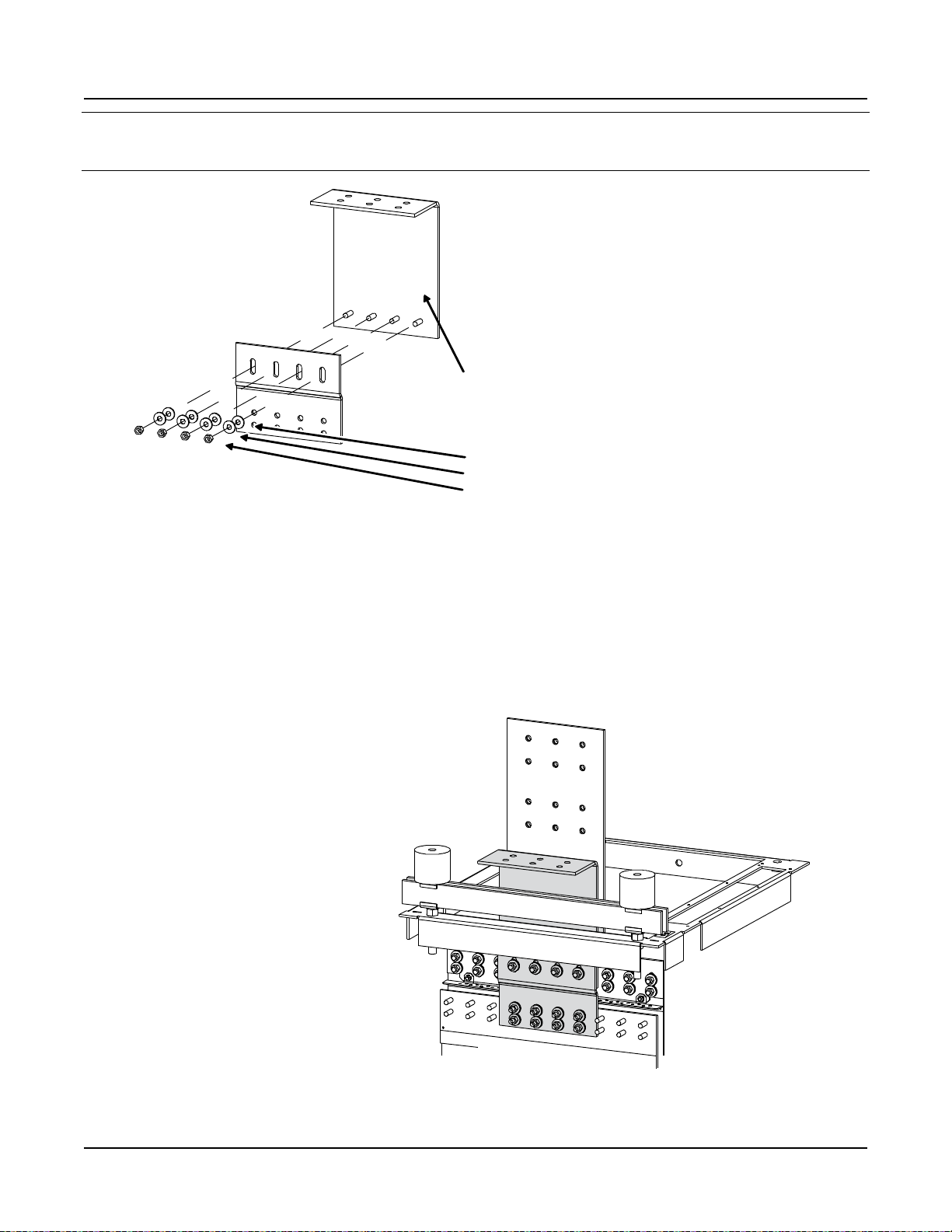
Install “Main Positive Busbar” onto
Bay Positive Busbar.
(1) Main Positive Busbar, P/N 554877
Note:Apply ElectricalAnti-Oxidation Compound
to busbar mating surfaces.
(12) 3/8” Flat Washer, P/N 214204100
(12) 3/8” Belleville Washer,P/N 214825000
(12) 3/8-16 Hex Nut, P/N 228567100
Hand-tighten only.
Note: Concave side of Bellville washer faces
busbar; convex side faces hex nut.
Rear Top
of Bay
Assembled
View
Do the following first before assembly:
1. Remove 552402 (1) and 116638 (4) from Bay.
2. Mount 554880 to the 554877 with 116638 (3).
Issue AM, March 26, 2014 Spec. No. 582140000 (Models 802NLDB, 802NLEB and 802NL-B)
Power/Distribution Bay
External Top-Mount Vertical Battery Input Busbar Assembly (P/N 554874)
Assembly Procedure Step 1
Page 38
This document is property of Emerson Network Power, Energy Systems, North America, Inc. and contains confidential and proprietary information owned by Emerson Network Power, Energy
Systems, North America, Inc. Any copying, use, or disclosure of it without the written permission of Emerson Network Power, Energy Systems, North America, Inc. is strictly prohibited.
Page 41

Installation Guide Section 5957
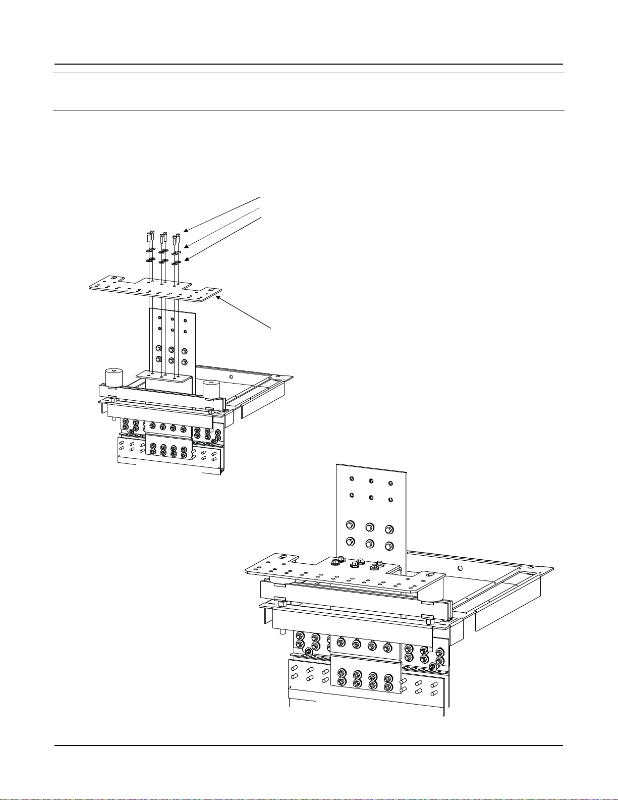
STEP 2
Install “Support Bar” and “Related
Hardware” onto Top of Bay.
(2) Threaded Insulator, P/N 245857200 Torque to 715 in-lbs.
(2) 5/8-11 x 7” Threaded Rod, P/N 334317000
(2) Support Bar Clip, P/N 351322300
(2) Support Bar, P/N 237790100
(2) Support Bar Clip, P/N 351322300
(2) 5/8” Lock Washer, P/N 215111800
(2) 5/8” Hex Nut, P/N 228580900 Leave 1/2” space between
bottom of nut and top of bay.
Rear Top
of Bay
Assembled
View
Spec. No. 582140000 (Models 802NLDB, 802NLEB and 802NL-B) Issue AM, March 26, 2014
Power/Distribution Bay
External Top-Mount Vertical Battery Input Busbar Assembly (P/N 554874)
Assembly Procedure Step 2
This document is property of Emerson Network Power, Energy Systems, North America, Inc. and contains confidential and proprietary information owned by Emerson Network Power, Energy
Systems, North America, Inc. Any copying, use, or disclosure of it without the written permission of Emerson Network Power, Energy Systems, North America, Inc. is strictly prohibited.
Page 39
Page 42

Section 5957 Installation Guide
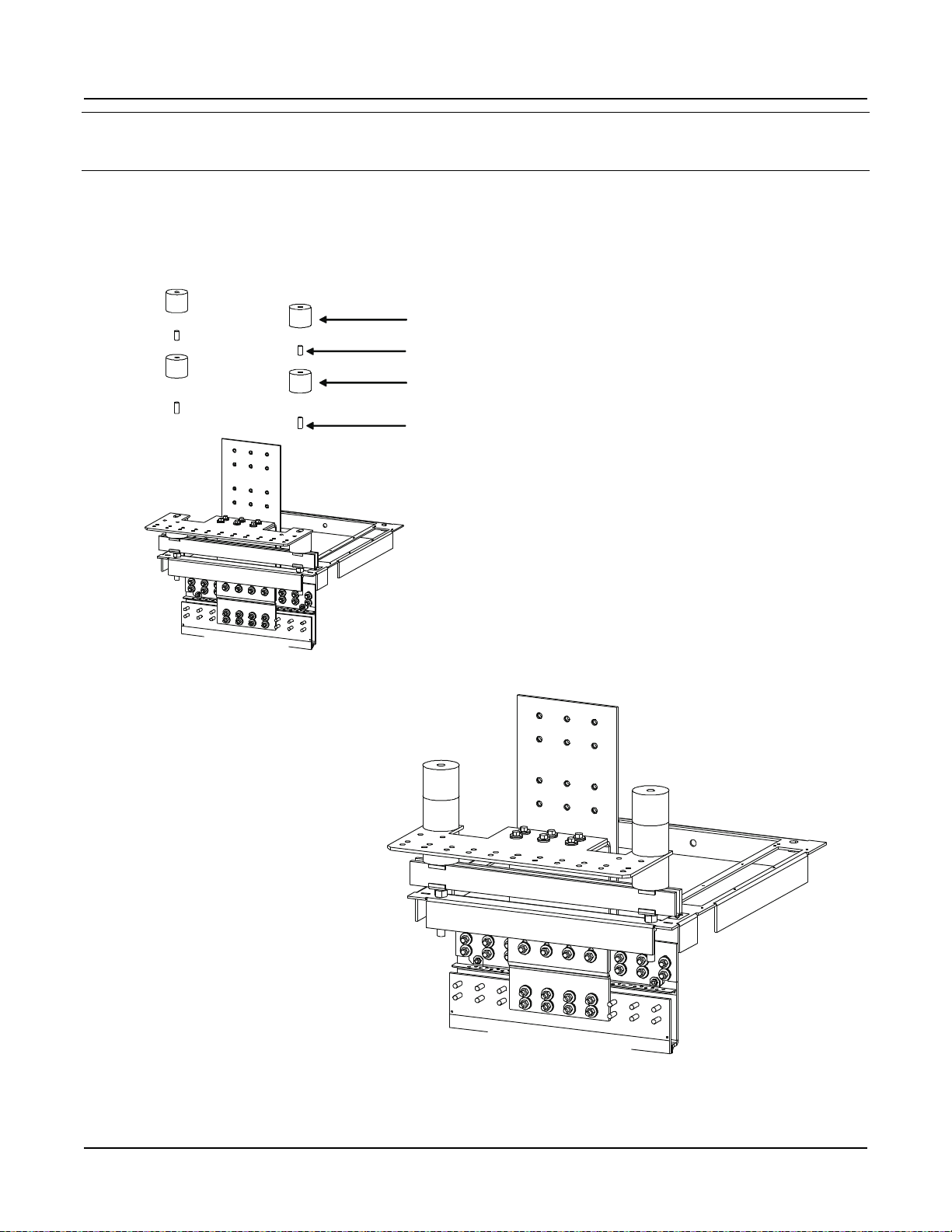
(1) Main Negative Busbar, P/N 554875
Note: Apply ElectricalAnti-Oxidation Compound
to busbar mating services.
Note: Concave side of Belleville washer faces
busbar; convex side faces hex nut.
(8) 3/8” Flat Washer, P/N 214204100
(8) 3/8” Belleville Washer, P/N 214825000
(8) 3/8-16 Hex Nut, P/N 228567100 Hand-tighten only.
Rear Top
of Bay
Assembled
View
STEP 3
Install “Main Negative Busbar” onto Bay
Negative Busbar.
Mount 554876 to the 554875.
Hardware:
214204100 (4)
214825000 (4)
228567100 (4)
Issue AM, March 26, 2014 Spec. No. 582140000 (Models 802NLDB, 802NLEB and 802NL-B)
Power/Distribution Bay
External Top-Mount Vertical Battery Input Busbar Assembly (P/N 554874)
Assembly Procedure Step 3
Page 40
This document is property of Emerson Network Power, Energy Systems, North America, Inc. and contains confidential and proprietary information owned by Emerson Network Power, Energy
Systems, North America, Inc. Any copying, use, or disclosure of it without the written permission of Emerson Network Power, Energy Systems, North America, Inc. is strictly prohibited.
Page 43

Installation Guide Section 5957
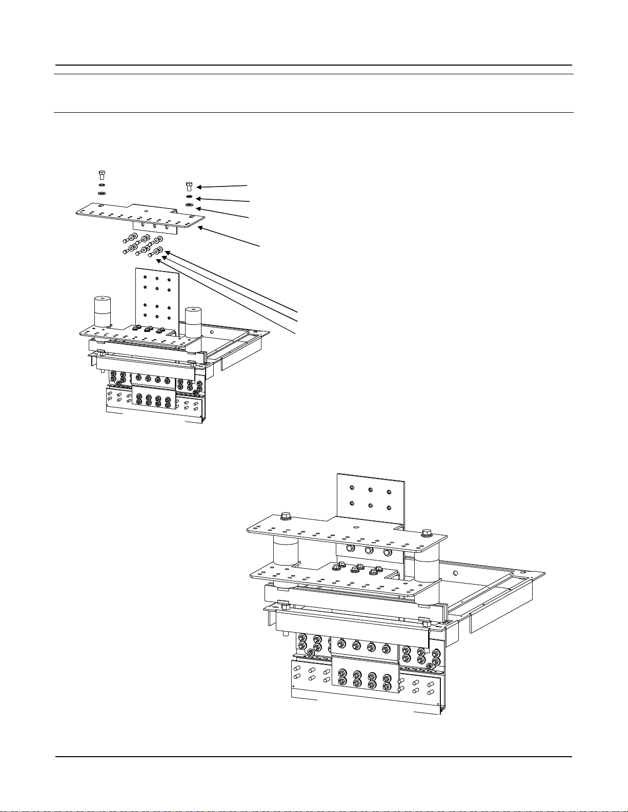
Note: Concave side of Belleville washer faces
busbar; convex side faces bolt head.
(6) 3/8-16 x 1-1/4” Bolt, P/N 227646800 Torque to 180 in-lbs.
(6) 3/8” Belleville Washer, P/N 214825000
(6) 3/8” Flat Washer, P/N 214204100
Note: Apply electrical anti-oxidation compound
to busbar mating surfaces.
(1) Vertical Landing Negative Busbar, P/N 548000
Rear Top
of Bay
Assembled
View
STEP 4
Install “Vertical Landing Negative Busbar”
onto “Main Negative Busbar”.
Spec. No. 582140000 (Models 802NLDB, 802NLEB and 802NL-B) Issue AM, March 26, 2014
Power/Distribution Bay
External Top-Mount Vertical Battery Input Busbar Assembly (P/N 554874)
Assembly Procedure Step 4
This document is property of Emerson Network Power, Energy Systems, North America, Inc. and contains confidential and proprietary information owned by Emerson Network Power, Energy
Systems, North America, Inc. Any copying, use, or disclosure of it without the written permission of Emerson Network Power, Energy Systems, North America, Inc. is strictly prohibited.
Page 41
Page 44

Section 5957 Installation Guide
(2) 5/8-11 x 1-1/2” Threaded Rod, P/N 334315900
(2) Threaded Insulator, P/N 245857200 Hand-tighten only.
(2) 5/8-11 x 1-1/4” Threaded Rod, P/N 334315700
(2) Threaded Insulator, P/N 245857200 Hand-tighten only.
Rear Top
of Bay
Assembled
View
STEP 5
Install “Threaded Insulators” onto
“Vertical Landing Negative Busbar”.
Issue AM, March 26, 2014 Spec. No. 582140000 (Models 802NLDB, 802NLEB and 802NL-B)
Power/Distribution Bay
External Top-Mount Vertical Battery Input Busbar Assembly (P/N 554874)
Assembly Procedure Step 5
Page 42
This document is property of Emerson Network Power, Energy Systems, North America, Inc. and contains confidential and proprietary information owned by Emerson Network Power, Energy
Systems, North America, Inc. Any copying, use, or disclosure of it without the written permission of Emerson Network Power, Energy Systems, North America, Inc. is strictly prohibited.
Page 45

Installation Guide Section 5957
(6) 3/8-16 x 1-1/4” Bolt, P/N 227646800 Torque to 180 in-lbs.
(6) 3/8” Belleville Washer, P/N 214825000
(6) 3/8” Flat Washer, P/N 214204100
(1) Vertical Landing Positive Busbar, P/N 548003
(2) 5/8-11 x 1” Bolt, P/N 227655100 Torque to 715 in-lbs.
(2) 5/8” Lock Washer, P/N 215111800
(2) 58” Flat Washer, P/N 214201300
STEP 6
Install “Vertical Landing Positive Busbar”
onto “Main Positive Busbar”.
Rear Top
of Bay
Assembled
View
Spec. No. 582140000 (Models 802NLDB, 802NLEB and 802NL-B) Issue AM, March 26, 2014
Power/Distribution Bay
External Top-Mount Vertical Battery Input Busbar Assembly (P/N 554874)
Assembly Procedure Step 6
This document is property of Emerson Network Power, Energy Systems, North America, Inc. and contains confidential and proprietary information owned by Emerson Network Power, Energy
Systems, North America, Inc. Any copying, use, or disclosure of it without the written permission of Emerson Network Power, Energy Systems, North America, Inc. is strictly prohibited.
Page 43
Page 46

Section 5957 Installation Guide
Torque these connections
to 180 in-lbs (20 places).
STEP 7
Final Torque
Rear Top
of Bay
Issue AM, March 26, 2014 Spec. No. 582140000 (Models 802NLDB, 802NLEB and 802NL-B)
Power/Distribution Bay
External Top-Mount Vertical Battery Input Busbar Assembly (P/N 554874)
Assembly Procedure Step 7
Page 44
This document is property of Emerson Network Power, Energy Systems, North America, Inc. and contains confidential and proprietary information owned by Emerson Network Power, Energy
Systems, North America, Inc. Any copying, use, or disclosure of it without the written permission of Emerson Network Power, Energy Systems, North America, Inc. is strictly prohibited.
Page 47

Installation Guide Section 5957
(2) Standoff Insulator, P/N 117843
(1) Plastic Shield, P/N 548002
(4) 14-20 x 3/8” Pan Head Tap Screw, P/N 218708200
STEP 8
Install Shield
Assembled
View
Spec. No. 582140000 (Models 802NLDB, 802NLEB and 802NL-B) Issue AM, March 26, 2014
Power/Distribution Bay
External Top-Mount Vertical Battery Input Busbar Assembly (P/N 554874)
Assembly Procedure Step 8
This document is property of Emerson Network Power, Energy Systems, North America, Inc. and contains confidential and proprietary information owned by Emerson Network Power, Energy
Systems, North America, Inc. Any copying, use, or disclosure of it without the written permission of Emerson Network Power, Energy Systems, North America, Inc. is strictly prohibited.
Page 45
Page 48

Section 5957 Installation Guide
3-Pole
1 12 13 24
25 36 37 48
Distribution Device
Top Mounting Studs
Distribution Device
Power System Connectors
Distribution Device
Bottom Mounting Studs
Distr.
Bus
#2
Distr.
Bus
#1
Right Half
Distr. Bus
#1 and #2
Left Half
Distr. Bus
#1 and #2
Belleville Lock Washer
3/8-16 Nut
Torque to
180 in-lbs
Torque to
84 in-lbs
Flat Washer
Lock Washer
1/4-20 Nut
Bullet Nose-Type Device
Mounting Assembly
Note: Each half of each bus MUST be populated
with distribution devices from left-to-right,
without skipping any distribution device mounting
positions within each half.
Front View
TPL Fuseholders
218 Circuit Breakers
1-Pole 2-Pole 3-Pole 4-Pole
2-Pole 3-Pole
Issue AM, March 26, 2014 Spec. No. 582140000 (Models 802NLDB, 802NLEB and 802NL-B)
Installing 218 Circuit Breakers, TPL Fuseholders, and Bullet Nose-Type Device Mounting Assemblies
into Power/Distribution Bays
Page 46
This document is property of Emerson Network Power, Energy Systems, North America, Inc. and contains confidential and proprietary information owned by Emerson Network Power, Energy
Systems, North America, Inc. Any copying, use, or disclosure of it without the written permission of Emerson Network Power, Energy Systems, North America, Inc. is strictly prohibited.
Page 49

Installation Guide Section 5957
* IncludesLoad Lug Adapter Plate,
plus 1/4" and 3/8" Mtg. Hardware.
Bus #1
Distribution Device
Mounting Location
Position 1 (left),
Position 24 (right)
Bus #2
Distribution Device
Mounting Location
Position 25 (left),
Position 48 (right)
Front View
Load Lug Adapter
Plate P/N 513701,
Kit P/N 520892*
Load Lug Adapter
Plate P/N 514765,
Kit P/N 520894*
Load Lug Adapter
Plate P/N 513702,
Kit P/N 520893*
Load Lug Adapter
Plate P/N 513700,
Kit P/N 520891*
to Distribution:
Bus #1
Position #12
to Distribution:
Bus #2
Position #25
to Distribution:
Bus #2
Position #36
to Distribution:
Bus #1
Position #1
to Distribution:
Bus #1
Position #13
to Distribution:
Bus #1
Position #24
to Distribution:
Bus #2
Position #37
to Distribution:
Bus #2
Position #48
1 12 13 24
25 36 37 48
Load Lug and/or
Load Lug Adapter Plate
Mounting Locations
REFER TO DISTRIBUTION DEVICES ILLUSTRATIONS
FOR PROPER LOAD LUG ADAPTER SELECTION
NOTE THATBULLET NOSE-TYPE DEVICE MOUNTING
ASSEMBLIES DO NOT REQUIRE LOAD LUG ADAPTER PLATES
Torque to
84 in-lbs
Hardware Build-Up
Load Lug Adapter Mounting Studs
Load Lug Adapter Plate
Flat Washer
Lock Washer
1/4-20 Nut
Spec. No. 582140000 (Models 802NLDB, 802NLEB and 802NL-B) Issue AM, March 26, 2014
Installing Load Lug Adapter Plates
into Power/Distribution Bays
This document is property of Emerson Network Power, Energy Systems, North America, Inc. and contains confidential and proprietary information owned by Emerson Network Power, Energy
Systems, North America, Inc. Any copying, use, or disclosure of it without the written permission of Emerson Network Power, Energy Systems, North America, Inc. is strictly prohibited.
Page 47
Page 50

Section 5957 Installation Guide
Issue AM, March 26, 2014 Spec. No. 582140000 (Models 802NLDB, 802NLEB and 802NL-B)
Installing 218 Circuit Breakers and TPL Fuseholders
into Distribution Only Bays
Page 48
This document is property of Emerson Network Power, Energy Systems, North America, Inc. and contains confidential and proprietary information owned by Emerson Network Power, Energy
Systems, North America, Inc. Any copying, use, or disclosure of it without the written permission of Emerson Network Power, Energy Systems, North America, Inc. is strictly prohibited.
Page 51

Installation Guide Section 5957
to Distribution:
Bus #2
Position #24
to Distribution:
Bus #2
Position #19
to Distribution:
Bus #2
Position #18
to Distribution:
Bus #2
Position #13
to Distribution:
Bus #4
Position #48
to Distribution:
Bus #4
Position #43
to Distribution:
Bus #4
Position #42
to Distribution:
Bus #4
Position #37
to Distribution:
Bus #1
Position #1
to Distribution:
Bus #1
Position #6
to Distribution:
Bus #1
Position #7
to Distribution:
Bus #1
Position #12
to Distribution:
Bus #3
Position #25
to Distribution:
Bus #3
Position #30
to Distribution:
Bus #3
Position #31
to Distribution:
Bus #3
Position #36
Rear cover panels removed in illustration for clarity.
Rear View Rear View
Load Lug and/or
Load Lug Adapter Kit
Mounting Locations
Spec. No. 582140000 (Models 802NLDB, 802NLEB and 802NL-B) Issue AM, March 26, 2014
Installing Load Lug Adapter Plates
into Distribution Only Bays
This document is property of Emerson Network Power, Energy Systems, North America, Inc. and contains confidential and proprietary information owned by Emerson Network Power, Energy
Systems, North America, Inc. Any copying, use, or disclosure of it without the written permission of Emerson Network Power, Energy Systems, North America, Inc. is strictly prohibited.
Page 49
Page 52

Section 5957 Installation Guide
NOTE THAT 1-POLE 218 CIRCUIT BREAKERS
DO NOT REQUIRE LOAD LUG ADAPTER PLATES
2-Position
Lug Adapter Kit
P/N 529132
3-Position
Lug Adapter Kit
P/N 529131
4-Position
Lug Adapter Kit
P/N 534420
1-Position Devices
(Load Busbars with NO
Lug Adapters Installed)
Issue AM, March 26, 2014 Spec. No. 582140000 (Models 802NLDB, 802NLEB and 802NL-B)
Installing Load Lug Adapter Plates
into Distribution Only Bays (continuation)
Page 50
This document is property of Emerson Network Power, Energy Systems, North America, Inc. and contains confidential and proprietary information owned by Emerson Network Power, Energy
Systems, North America, Inc. Any copying, use, or disclosure of it without the written permission of Emerson Network Power, Energy Systems, North America, Inc. is strictly prohibited.
Page 53

Installation Guide Section 5957
Customer
Supplied
Lug
Busbars
P/O Dist.
Bay
2-Position
Lug Adapter Kit
P/N 529132
Customer
Supplied
Lug
Customer
Supplied
Lugs
Customer
Supplied
Lugs
Busbars
P/O Dist.
Bay
Note: Apply Electrical Anti-Oxidation
Compound to all Busbar
Mating Surfaces.
Note: Concave Side of Belleville Washer Faces Busbar,
Convex Side Faces Bolt or Nut.
(1) Spacer Busbar,
P/N 528806
(1) Adapter Busbar,
P/N 528794
(2) 3/8-16 Hex Nut,
P/N 228567100
(2) 3/8" Flat Washer,
P/N 214204100
(1) 3/8-16 Hex Nut,
P/N 228567100
(1) 3/8" Flat Washer,
P/N 214204100
Torque to 180 in-lbs.
(1) 1/4-20 x 7/8" Bolt,
P/N 227640500
(1) 1/4" Flat Washer,
P/N 214110100
(2) 3/8-16 x 1-1/2" Bolt,
P/N 227647000
(2) 3/8" Belleville Lock Washer,
P/N 214825000
(4) 3/8-16 x 1-1/2" Bolt,
P/N 227647000
(4) 3/8" Flat Washer,
P/N 214112100
(1) 3/8-16 x 1" Bolt,
P/N 227646600
(1) 3/8" Belleville Lock Washer,
P/N 214825000
(1) 1/4-20 x 7/8" Bolt,
P/N 227640500
(1) 1/4" Flat Washer,
P/N 214110100
(1) Adapter Busbar,
P/N 528794
(8) 3/8-16 Hex Nut,
P/N 228567100
(8) 3/8" Lock Washer
P/N 215111300
(8) 3/8" Flat Washer,
P/N 214112100
Torque to 300 in-lbs.
Torque to 84 in-lbs.
Torque to 84 in-lbs.
(1) 1/4-20 Hex Nut,
P/N 228557100
(1) 1/4" Lock Washer
P/N 215111100
(1) 1/4" Flat Washer,
P/N 214110100
Spec. No. 582140000 (Models 802NLDB, 802NLEB and 802NL-B) Issue AM, March 26, 2014
Installing Load Lug Adapter Plates
into Distribution Only Bays (continuation)
This document is property of Emerson Network Power, Energy Systems, North America, Inc. and contains confidential and proprietary information owned by Emerson Network Power, Energy
Systems, North America, Inc. Any copying, use, or disclosure of it without the written permission of Emerson Network Power, Energy Systems, North America, Inc. is strictly prohibited.
Page 51
Page 54

Section 5957 Installation Guide
3-Position
Lug Adapter Kit
P/N 529131
Customer
Supplied
Lugs
Customer
Supplied
Lugs
Customer
Supplied
Lugs
Customer
Supplied
Lugs
Busbars
P/O Dist.
Bay
Busbars
P/O Dist.
Bay
Note: Apply Electrical Anti-Oxidation
Compound to all Busbar
Mating Surfaces.
Note: Concave Side of Belleville Washer Faces Busbar,
Convex Side Faces Bolt or Nut.
(1) Adapter Busbar,
P/N 528795
(1) Spacer Busbar,
P/N 528806
(1) Spacer Busbar,
P/N 528806
(1) Adapter Busbar,
P/N 528795
Torque to 180 in-lbs.
(4) 3/8-16 Hex Nut,
P/N 228567100
(4) 3/8" Flat Washer,
P/N 214204100
(4) 3/8-16 x 1-1/2" Bolt,
P/N 227647000
(4) 3/8" Belleville Lock Washer,
P/N 214825000
(4) 3/8-16 x 1" Bolt,
P/N 227646600
(4) 3/8" Belleville Lock Washer,
P/N 214825000
(4) 3/8-16 Hex Nut,
P/N 228567100
(4) 3/8" Flat Washer,
P/N 214204100
(2) 1/4-20 x 5/8" Bolt,
P/N 227640300
(2) 1/4" Lock Washer,
P/N 215111100
(2) 1/4" Flat Washer,
P/N 214110100
Torque to 180 in-lbs.
(2) 3/8-16 Hex Nut,
P/N 228567100
(2) 3/8" Flat Washer,
P/N 214204100
(4) 3/8-16 Hex Nut,
P/N 228567100
(4) 3/8" Flat Washer,
P/N 214204100
(4) 3/8-16 x 1-1/2" Bolt,
P/N 227647000
(4) 3/8" Belleville Lock Washer,
P/N 214825000
(2) 3/8-16 x 1" Bolt,
P/N 227646600
(2) 3/8" Belleville Lock Washer,
P/N 214825000
(1) 1/4-20 x 5/8" Bolt,
P/N 227640300
(1) 1/4" Lock Washer,
P/N 215111100
(1) 1/4" Flat Washer,
P/N 214110100
Torque to 84 in-lbs.
Torque to 84 in-lbs.
Issue AM, March 26, 2014 Spec. No. 582140000 (Models 802NLDB, 802NLEB and 802NL-B)
Installing Load Lug Adapter Plates
into Distribution Only Bays (continuation)
Page 52
This document is property of Emerson Network Power, Energy Systems, North America, Inc. and contains confidential and proprietary information owned by Emerson Network Power, Energy
Systems, North America, Inc. Any copying, use, or disclosure of it without the written permission of Emerson Network Power, Energy Systems, North America, Inc. is strictly prohibited.
Page 55

Installation Guide Section 5957
4-Position
Lug Adapter Kit
P/N 534420
Busbars
P/O Dist.
Bay
Customer
Supplied
Lugs
Customer
Supplied
Lugs
(4) 3/8-16 x 1-1/2" Bolt,
P/N 227647000
(4) 3/8" Belleville Lock Washer,
P/N 214825000
Torque to 180 in-lbs.
(1) Adapter Busbar,
P/N 534421
(1) Spacer Busbar,
P/N 528806
(1) Adapter Busbar,
P/N 534421
(8) 3/8-16 Hex Nut,
P/N 228567100
(8) 3/8" Flat Washer,
P/N 214204100
(4) 3/8-16 x 2" Bolt,
P/N 227647400
(4) 3/8" Belleville Lock Washer,
P/N 214825000
Note: Apply Electrical Anti-Oxidation
Compound to all Busbar
Mating Surfaces.
Note: Concave Side of Belleville Washer Faces Busbar,
Convex Side Faces Bolt or Nut.
Spec. No. 582140000 (Models 802NLDB, 802NLEB and 802NL-B) Issue AM, March 26, 2014
Installing Load Lug Adapter Plates
into Distribution Only Bays (continuation)
This document is property of Emerson Network Power, Energy Systems, North America, Inc. and contains confidential and proprietary information owned by Emerson Network Power, Energy
Systems, North America, Inc. Any copying, use, or disclosure of it without the written permission of Emerson Network Power, Energy Systems, North America, Inc. is strictly prohibited.
Page 53
Page 56

Section 5957 Installation Guide
1-Pole 218 Circuit
Breakers Assemblies
Load Lug Adapter Plate
for 1-Pole Devices
1.000"
3/8" Clearance Holes
Lug Adapter P/N 513700,
Kit P/N 520891
(see Notes 1, 2, 3)
2-Pole 218 Circuit
Breaker Assemblies
Load Lug Adapter Plate
for 2-Pole Devices
3/8" Clearance Holes
Lug Adapter P/N 513701,
Kit P/N 520892
(see Notes 1, 2, 3)
NO LUG ADAPTER KITS
REQUIRED WHEN USED IN
DISTRIBUTION ONLY BAYS
Lug Adapter Kits
Power/Distribution Bays
Lug Adapter Kits
Distribution Only Bays
2-Position
Lug Adapter Kit
P/N 529132
(see Notes 4, 6, 7, 8)
Lug Adapter Kits
Power/Distribution Bays
Lug Adapter Kits
Distribution Only Bays
Notes:
1. Maximum size of wire to be connected to a single lug position is 750 kcmil.
2. Maximum lug width is 1.937 inches.
3. Kit includes Load Lug Adapter Plate, plus 1/4" and 3/8" mtg. hardware.
4. Lug adapter accepts a maximum of (2) 750 kcmil or (4) 350 kcmil lugs.
5. Lug adapter accepts a maximum of (4) 750 kcmil lugs.
6. Lugs are not part of the kit, shown for illustration only.
7. Bay busbars are not part of the kit, shown for illustration only.
8. Two (2) kits shown for illustration of the kit installed on busbars with tops
even with each other and staggered.
1.000"
3/8" Clearance Hole
1.000"
Issue AM, March 26, 2014 Spec. No. 582140000 (Models 802NLDB, 802NLEB and 802NL-B)
218 Circuit Breakers Lug Adapter Kits
Page 54
This document is property of Emerson Network Power, Energy Systems, North America, Inc. and contains confidential and proprietary information owned by Emerson Network Power, Energy
Systems, North America, Inc. Any copying, use, or disclosure of it without the written permission of Emerson Network Power, Energy Systems, North America, Inc. is strictly prohibited.
Page 57

Installation Guide Section 5957
4-Pole 218 Circuit
Breaker Assemblies
3-Pole 218 Circuit
Breaker Assemblies
Load Lug Adapter Plate
for 3-Pole Devices
1.000"
2.000"
3/8" Clearance Holes
Lug Adapter P/N 513702,
Kit P/N 520893
(see Notes 1, 2, 3)
Lug Adapter Kits
Power/Distribution Bays
Load Lug Adapter Plate
for 4-Pole Devices
2.000"
1.000"
3/8" Clearance Holes
Lug Adapter P/N 514765,
Kit P/N 520894
(see Notes 1, 2, 3)
Lug Adapter Kits
Power/Distribution Bays
Notes:
1. Maximum size of wire to be connected to a single lug position is 750 kcmil.
2. Maximum lug width is 1.937 inches.
3. Kit includes Load Lug Adapter Plate, plus 1/4" and 3/8" mtg. hardware.
4. Lug adapter accepts a maximum of (2) 750 kcmil or (4) 350 kcmil lugs.
5. Lug adapter accepts a maximum of (4) 750 kcmil lugs.
6. Lugs are not part of the kit, shown for illustration only.
7. Bay busbars are not part of the kit, shown for illustration only.
8. Two (2) kits shown for illustration of the kit installed on busbars with tops
even with each other and staggered.
3-Position
Lug Adapter Kit
P/N 529131
(see Notes 5, 6, 7, 8)
Lug Adapter Kits
Distribution Only Bays
3/8" Clearance Hole
1.000"
4-Position
Lug Adapter Kit
P/N 534420
(see Notes 5, 6, 7)
Lug Adapter Kits
Distribution Only Bays
3/8" Clearance Hole
1.000"
Spec. No. 582140000 (Models 802NLDB, 802NLEB and 802NL-B) Issue AM, March 26, 2014
This document is property of Emerson Network Power, Energy Systems, North America, Inc. and contains confidential and proprietary information owned by Emerson Network Power, Energy
Systems, North America, Inc. Any copying, use, or disclosure of it without the written permission of Emerson Network Power, Energy Systems, North America, Inc. is strictly prohibited.
Page 55
Page 58

Section 5957 Installation Guide
Fuseholder Assembly
P/N 514403
TPL Fuse
Load Lug Adapter Plate
1.000"
3/8" Clearance Holes
Lug Adapter P/N 513701,
Kit P/N 520892
(see Notes 1, 2, 3)
Notes:
1. Maximum size of wire to be connected to a single lug position is 750 kcmil.
2. Maximum lug width is 1.937 inches.
3. Kit includes Load Lug Adapter Plate, plus 1/4" and 3/8" mtg. hardware.
4. Lug adapter accepts a maximum of (2) 750 kcmil or (4) 350 kcmil lugs.
5. Lug adapter accepts a maximum of (4) 750 kcmil lugs.
6. Lugs are not part of the kit, shown for illustration only.
7. Bay busbars are not part of the kit, shown for illustration only.
8. Two (2) kits shown for illustration of the kit installed on busbars with tops
even with each other and staggered.
Lug Adapter Kits
Power/Distribution Bays
2-Position
Lug Adapter Kit
P/N 529132
(see Notes 4, 6, 7, 8)
Lug Adapter Kits
Distribution Only Bays
3/8" Clearance Hole
1.000"
GMT-18/100A
Alarm Fuse
and GMT-X
Safety Fuse Cover
Issue AM, March 26, 2014 Spec. No. 582140000 (Models 802NLDB, 802NLEB and 802NL-B)
TPL Fuses Lug Adapter Kits
Page 56
This document is property of Emerson Network Power, Energy Systems, North America, Inc. and contains confidential and proprietary information owned by Emerson Network Power, Energy
Systems, North America, Inc. Any copying, use, or disclosure of it without the written permission of Emerson Network Power, Energy Systems, North America, Inc. is strictly prohibited.
Page 59

Installation Guide Section 5957
Fuseholder Assembly
P/N 514404
TPL Fuse
GMT-18/100A
Alarm Fuse
and GMT-X
Safety Fuse Cover
Notes:
1. Maximum size of wire to be connected to a single lug position is 750 kcmil.
2. Maximum lug width is 1.937 inches.
3. Kit includes Load Lug Adapter Plate, plus 1/4" and 3/8" mtg. hardware.
4. Lug adapter accepts a maximum of (2) 750 kcmil or (4) 350 kcmil lugs.
5. Lug adapter accepts a maximum of (4) 750 kcmil lugs.
6. Lugs are not part of the kit, shown for illustration only.
7. Bay busbars are not part of the kit, shown for illustration only.
8. Two (2) kits shown for illustration of the kit installed on busbars with tops
even with each other and staggered.
Load Lug Adapter Plate
1.000"
2.000"
3/8" Clearance Holes
Lug Adapter P/N 513702,
Kit P/N 520893
(see Notes 1, 2, 3)
Lug Adapter Kits
Power/Distribution Bays
3-Position
Lug Adapter Kit
P/N 529131
(see Notes 5, 6, 7, 8)
Lug Adapter Kits
Distribution Only Bays
3/8" Clearance Hole
1.000"
Spec. No. 582140000 (Models 802NLDB, 802NLEB and 802NL-B) Issue AM, March 26, 2014
This document is property of Emerson Network Power, Energy Systems, North America, Inc. and contains confidential and proprietary information owned by Emerson Network Power, Energy
Systems, North America, Inc. Any copying, use, or disclosure of it without the written permission of Emerson Network Power, Energy Systems, North America, Inc. is strictly prohibited.
Page 57
Page 60

Section 5957 Installation Guide
TLS/TPS Fuses
Bullet Nose Device
Mounting Assembly,
P/N 513747
Fuseholder Assembly
P/N 514403 P/N 514404
TPL Fuses
Flat Washer
Lock Washer
Nut
Torque to
168 in-lbs
TPL
Fuse
Bullet Nose-Type
Circuit Breakers
Bullet Nose Device
Mounting Assembly,
P/N 513747
Toggle-handle
Breaker
Rocker-handle
Breaker
Issue AM, March 26, 2014 Spec. No. 582140000 (Models 802NLDB, 802NLEB and 802NL-B)
Installing TPL Fuses, TLS/TPS Fuses, and Bullet Nose-Type Circuit Breakers
Page 58
This document is property of Emerson Network Power, Energy Systems, North America, Inc. and contains confidential and proprietary information owned by Emerson Network Power, Energy
Systems, North America, Inc. Any copying, use, or disclosure of it without the written permission of Emerson Network Power, Energy Systems, North America, Inc. is strictly prohibited.
Page 61

Installation Guide Section 5957
TLS/TPS Fuses
Bullet Nose-Type
Circuit Breakers
Toggle
Handle
Breaker
Rocker
Handle
Breaker
Load leads are connected to load busbars.
These busbars provide 1/4-20 threaded holes
on 5/8” centers for installation of customer
provided two-hole lugs. Customer must
provide lug mounting bolts and additional
hardware. Bolt length: 3/4”.
Note:
Spec. No. 582140000 (Models 802NLDB, 802NLEB and 802NL-B) Issue AM, March 26, 2014
Installing TPL Fuses, TLS/TPS Fuses, and Bullet Nose-Type Circuit Breakers
This document is property of Emerson Network Power, Energy Systems, North America, Inc. and contains confidential and proprietary information owned by Emerson Network Power, Energy
Systems, North America, Inc. Any copying, use, or disclosure of it without the written permission of Emerson Network Power, Energy Systems, North America, Inc. is strictly prohibited.
Page 59
Page 62

Section 5957 Installation Guide
MCA Customer Alarm Relay
Circuit Card P/N 514348.
MCA I/O Circuit Card
P/N 524550
Install in any position in seven-slot
card cage in any bay. Component
side faces left as viewed from the front.
Power/Distribution Bay Shown,
Power Only Bay Similar
Issue AM, March 26, 2014 Spec. No. 582140000 (Models 802NLDB, 802NLEB and 802NL-B)
Installing the MCA Customer Alarm Relay Circuit Card(s) and MCA I/O Circuit Card(s)
into Power/Distribution and Power Only Bays
Page 60
This document is property of Emerson Network Power, Energy Systems, North America, Inc. and contains confidential and proprietary information owned by Emerson Network Power, Energy
Systems, North America, Inc. Any copying, use, or disclosure of it without the written permission of Emerson Network Power, Energy Systems, North America, Inc. is strictly prohibited.
Page 63

Installation Guide Section 5957
MCA Circuit Card
(Primary Power/Distribution
or Power Only Bay)
or
Router Circuit Card
(Secondary Power/Distribution Bays
and Distribution Only Bays)
MCA Circuit Card P/N 509478
(Primary Power/Distribution
or Power Only Bay)
RJ-45
Jack
MCA
Network
Connector
(for Left
Expansion)
MCA
Network
Connector
(for Right
Expansion)
1 10
RJ-45
Jack
RJ-45
Jack
RJ-45
Jack
RJ-45
Jack
RJ-45
Jack
MCA
Network
Connector
(for Left
Expansion)
MCA
Network
Connector
(for Right
Expansion)
MCA
Network
Connector
(for Left
Expansion)
MCA
Network
Connector
(for Right
Expansion)
Router Circuit Card P/N 509509
(Secondary Power/Distribution Bays,
Secondary Power Only Bays,
and Distribution Only Bays)
Router Circuit Card P/N 509509
(Secondary Power/Distribution Bays,
Secondary Power Only Bays,
and Distribution Only Bays)
MCA Network Cable
(Yellow Cable)
DO NOT USE BOTH
RJ-45 CONNECTORS
IN THE PRIMARY BAY
Power/Distribution Bay (front view)
(Power Only Bay Similar)
SYSTEM MONITORING
AND CONTROL SECTION
Front View
Distribution Only Bay
Front View
* In a Distribution Only Bay, install the
supplied ferrite cable clamp onto the
cable near the router circuit card.
Emerson P/N 242941100
FairRite P/N 0443164251
Steward P/N 28A20025-0A0
Spec. No. 582140000 (Models 802NLDB, 802NLEB and 802NL-B) Issue AM, March 26, 2014
MCA Network Bay-Bay Interconnections
This document is property of Emerson Network Power, Energy Systems, North America, Inc. and contains confidential and proprietary information owned by Emerson Network Power, Energy
Systems, North America, Inc. Any copying, use, or disclosure of it without the written permission of Emerson Network Power, Energy Systems, North America, Inc. is strictly prohibited.
Page 61
Page 64

Section 5957 Installation Guide
Front Door Removed in
Illustration for Clarity
Distribution Only Bay
Connect BAT RTN to this Terminal
Issue AM, March 26, 2014 Spec. No. 582140000 (Models 802NLDB, 802NLEB and 802NL-B)
Distribution Only Bay RTN Connection to System Monitoring and Control Section
Page 62
This document is property of Emerson Network Power, Energy Systems, North America, Inc. and contains confidential and proprietary information owned by Emerson Network Power, Energy
Systems, North America, Inc. Any copying, use, or disclosure of it without the written permission of Emerson Network Power, Energy Systems, North America, Inc. is strictly prohibited.
Page 65

Installation Guide Section 5957
SYSTEM MONITORING
AND CONTROL SECTION
MCA Battery Charge Digital Temperature
Compensation Probe Connector
(Primary Bay Only)
External
CAN BUS
Port
Battery Charge Digital
Temperature Compensation Probe
Power/Distribution Bay Shown,
Power Only Bay Similar
Spec. No. 582140000 (Models 802NLDB, 802NLEB and 802NL-B) Issue AM, March 26, 2014
MCA Battery Charge Digital Temperature Compensation Probe Connection
to Primary Power/Distribution and Power Only Bays
This document is property of Emerson Network Power, Energy Systems, North America, Inc. and contains confidential and proprietary information owned by Emerson Network Power, Energy
Systems, North America, Inc. Any copying, use, or disclosure of it without the written permission of Emerson Network Power, Energy Systems, North America, Inc. is strictly prohibited.
Page 63
Page 66

Section 5957 Installation Guide
SYSTEM MONITORING
AND CONTROL SECTION
MCA Circuit Card
(Primary Bay)
(See Detail A)
Seven-Slot Card Cage for MCA Circuit Cards
and/or LMS Input/Output (I/O) Circuit Cards.
(See Detail B)
Power/Distribution Bay Shown,
Power Only Bay Similar
Issue AM, March 26, 2014 Spec. No. 582140000 (Models 802NLDB, 802NLEB and 802NL-B)
MCA External Alarm, Reference, and Control Connections to Primary Power/Distribution and Power Only
Bays and I/O Card Connections to Primary and Secondary Power/Distribution and Power Only Bays
Page 64
This document is property of Emerson Network Power, Energy Systems, North America, Inc. and contains confidential and proprietary information owned by Emerson Network Power, Energy
Systems, North America, Inc. Any copying, use, or disclosure of it without the written permission of Emerson Network Power, Energy Systems, North America, Inc. is strictly prohibited.
Page 67

Installation Guide Section 5957
Detail A
MCA Circuit Card P/N 509478
(Primary Bay)
Remote
Equalize
Remote
HVS
PCU
Emergency
Stop (ESTOP)
Test
Input**
Dry Relay Contact
Closure to Activate
** Apply Test contact closure, then apply
HVS or ESTOP closure to test these circuits.
See MCA display to verify circuits operational.
External
Voltage Input
(for MCA Alarms
and Meter Reading*)
-VSense +VSense
1 10
* Automatic internal sense when not connected.
Note: If connected and removed, external
A/D Volt Alarm activates. Clear alarm by updating
inventory.
Fuse @
1-1/3 Amps
28-16 AWG
Torque to 2.0 in-lbs
Spec. No. 582140000 (Models 802NLDB, 802NLEB and 802NL-B) Issue AM, March 26, 2014
This document is property of Emerson Network Power, Energy Systems, North America, Inc. and contains confidential and proprietary information owned by Emerson Network Power, Energy
Systems, North America, Inc. Any copying, use, or disclosure of it without the written permission of Emerson Network Power, Energy Systems, North America, Inc. is strictly prohibited.
Page 65
Page 68

Section 5957 Installation Guide
MCA I/O Circuit Cards
(Primary and/or Secondary Bays)
(P/N 524550, 1 analog input, 1 analog output, 4 binary inputs)
1
12
TB1
B1***
B2***
B3***
B4***
A1 IN*
A1 OUT**
+
_
+
_
1
9
10
18
K3
K2
K1
K6
K5
K4
NC
COM
NO
NC
COM
NO
NC
COM
NO
NC
COM
NO
NC
COM
NO
NC
COM
NO
TB1
MCA Customer Alarm
Relay Circuit Card P/N 514348
(Primary and/or Secondary Bays)
Notes
NC = Normally Closed
COM = Common
NO = Normally Open
All relay contacts are shown
with the relay deenergized.
* 0-50 mv DC Shunt Input
** 0-50 mv DC Output for Remote Plant Output Current Monitoring
*** Dry Contacts, Circuit Closure to ActivateAlarm
Issue AM, March 26, 2014 Spec. No. 582140000 (Models 802NLDB, 802NLEB and 802NL-B)
Page 66
This document is property of Emerson Network Power, Energy Systems, North America, Inc. and contains confidential and proprietary information owned by Emerson Network Power, Energy
Systems, North America, Inc. Any copying, use, or disclosure of it without the written permission of Emerson Network Power, Energy Systems, North America, Inc. is strictly prohibited.
Page 69

Installation Guide Section 5957
1
9
10
18
K3
K2
K1
K6
K5
K4
NC
COM
NO
NC
COM
NO
NC
COM
NO
NC
COM
NO
NC
COM
NO
NC
COM
NO
TB1
Notes
NC = Normally Close Contact
COM = Common
NO = Normally Open Contact
All relay contacts are shown
with the relay de-energized.
All relays are energized
during normal operation,
and de-energized
during an alarm condition.
#1 #2 #3 #4 #5 #6 #7
1
9
10
18
K3
K2
K1
K6
K5
K4
NC
COM
NO
NC
COM
NO
NC
COM
NO
NC
COM
NO
NC
COM
NO
NC
COM
NO
TB1
1
9
10
18
K3
K2
K1
K6
K5
K4
NC
COM
NO
NC
COM
NO
NC
COM
NO
NC
COM
NO
NC
COM
NO
NC
COM
NO
TB1
1
9
10
18
K3
K2
K1
K6
K5
K4
NC
COM
NO
NC
COM
NO
NC
COM
NO
NC
COM
NO
NC
COM
NO
NC
COM
NO
TB1
1
9
10
18
K3
K2
K1
K6
K5
K4
NC
COM
NO
NC
COM
NO
NC
COM
NO
NC
COM
NO
NC
COM
NO
NC
COM
NO
TB1
1
9
10
18
K3
K2
K1
K6
K5
K4
NC
COM
NO
NC
COM
NO
NC
COM
NO
NC
COM
NO
NC
COM
NO
NC
COM
NO
TB1
1
9
10
18
K3
K2
K1
K6
K5
K4
NC
COM
NO
NC
COM
NO
NC
COM
NO
NC
COM
NO
NC
COM
NO
NC
COM
NO
TB1
#1
#3
#5
#7
#6
#4
#2
AC MAJOR
OVER
CURRENT
RECT. MINOR
UNDEFINED
MCA FAIL
AC
MINOR
AC MAJOR
OVER
CURRENT
RECT. MINOR
UNDEFINED
MCA FAIL
AC
MINOR
AUDIBLE
HIGH
VOLTAGE #2
VERY LOW
VOLTAGE
RECT. MAJOR
RECT. FAIL
TEST/EQ
AUDIBLE
HIGH
VOLTAGE #2
VERY LOW
VOLTAGE
RECT. MAJOR
RECT. FAIL
TEST/EQ
AC FAIL
MINOR
MAJOR
HIGH
VOLTAGE #1
BATTERY ON
DISCHARGE
BREAKER/FUSE
AC FAIL
MINOR
MAJOR
HIGH
VOLTAGE #1
BATTERY ON
DISCHARGE
BREAKER/FUSE
UNDEFINED
UNDEFINED
UNDEFINED
Controller Conditions
that are Logged and
that Light the Bay #1
Alarm LED
UNDEFINED
UNDEFINED
Spec. No. 582140000 (Models 802NLDB, 802NLEB and 802NL-B) Issue AM, March 26, 2014
Default MCA Customer Alarm Relay Assignments
This document is property of Emerson Network Power, Energy Systems, North America, Inc. and contains confidential and proprietary information owned by Emerson Network Power, Energy
Systems, North America, Inc. Any copying, use, or disclosure of it without the written permission of Emerson Network Power, Energy Systems, North America, Inc. is strictly prohibited.
Page 67
Page 70

Section 5957 Installation Guide
LMS LOCAL PORT
(USB)
(active only if
optional LMS installed)
(Provided via a USB to RS-232 PortAdapter Unit)
Primary
Bay
Detail A
15
9 6
Mating Connector
in Power System Wire Harness
(9-Pin Female D-Type Jack)
If required to connect to a serial
port, disconnect the factory plug to
the “USB to RS-232 Port Adapter
Unit” and connect to this plug.
Power/Distribution Bay Shown,
Power Only Bay Similar
Issue AM, March 26, 2014 Spec. No. 582140000 (Models 802NLDB, 802NLEB and 802NL-B)
MCA Local Control Panel and Display and LMS Local Port
Page 68
This document is property of Emerson Network Power, Energy Systems, North America, Inc. and contains confidential and proprietary information owned by Emerson Network Power, Energy
Systems, North America, Inc. Any copying, use, or disclosure of it without the written permission of Emerson Network Power, Energy Systems, North America, Inc. is strictly prohibited.
Page 71

Installation Guide Section 5957
Spec. No. 582140000 (Models 802NLDB, 802NLEB and 802NL-B) Issue AM, March 26, 2014
LMS Local Port
Introduction
The LMS Local Port is provided via a USB to RS-232 Port Adapter Unit. The proper
device driver must be installed on the computer to be connected to the USB port. Use
one of the following procedures to install the device driver.
Installing the USB Device Driver from the Furnished CD
A device driver CD is supplied with the USB to RS-232 Port Adapter Unit. The proper
driver must be installed on the computer to be connected to the USB port. Use the
provided CD to install the driver.
Downloading the USB Driver from the Web
1) Go to this link http://vscom.de/downloadcenter.htm.
2) Select “USB to Serial Drivers” from the Product Category drop-down menu.
3) Select your product model’s “Driver and Documentation” to download the files.
4) Select your computer’s operating system.
5) Run or save the application.
Setting up your Computer to Access the Power System
1) Select Hyper terminal.
2) Connect using one of the unused COM ports. (e.g. COM 5)
3) Set Bit Per Second to 19200.
4) Set Data Bits to 8.
5) Set Parity to None.
6) Set Stop bits to 1.
7) Set Flow control to Hardware.
8) Select OK.
9) In Hyper terminal press ENTER.
10) Enter the password 6.
11) Enter “?” to see commands.
This document is property of Emerson Network Power, Energy Systems, North America, Inc. and contains confidential and proprietary information owned by Emerson Network Power, Energy
Systems, North America, Inc. Any copying, use, or disclosure of it without the written permission of Emerson Network Power, Energy Systems, North America, Inc. is strictly prohibited.
Page 69
Page 72

Section 5957 Installation Guide
Two holes with 1/4-20 captive
nuts provided for installation of
customer provided two-hole lug
with 1/4" bolt clearance holes
on 5/8" centers
Two holes with 1/4-20 captive
nuts provided for installation of
customer provided two-hole lug
with 1/4" bolt clearance holes
on 5/8" centers
Top View
Recm. Torque
1/4" Hardware
using Belleville
Lock Washer
60 in-lbs.
Power/Distribution Bay Shown,
Power Only Bay Similar
Issue AM, March 26, 2014 Spec. No. 582140000 (Models 802NLDB, 802NLEB and 802NL-B)
Power/Distribution and Power Only Bays Frame Grounding Connection
Page 70
This document is property of Emerson Network Power, Energy Systems, North America, Inc. and contains confidential and proprietary information owned by Emerson Network Power, Energy
Systems, North America, Inc. Any copying, use, or disclosure of it without the written permission of Emerson Network Power, Energy Systems, North America, Inc. is strictly prohibited.
Page 73

Installation Guide Section 5957
1/4" clearance holes
on 5/8” centers are
provided for installation
of customer provided
two-hole lug.
1/4" clearance holes
on 5/8” centers are
provided for installation
of customer provided
two-hole lug.
Top View
Distribution Only Bay
Recm. Torque
1/4” Hardware
using Belleville
Lock Washer
60 in-lbs.
Spec. No. 582140000 (Models 802NLDB, 802NLEB and 802NL-B) Issue AM, March 26, 2014
Distribution Only Bay Frame Grounding Connection
This document is property of Emerson Network Power, Energy Systems, North America, Inc. and contains confidential and proprietary information owned by Emerson Network Power, Energy
Systems, North America, Inc. Any copying, use, or disclosure of it without the written permission of Emerson Network Power, Energy Systems, North America, Inc. is strictly prohibited.
Page 71
Page 74

* Includes Load Lug Adapter Plate,
plus 1/4" and 3/8" Mtg. Hardware.
Bus #1
Distribution Device
Mounting Location
Position 1 (left),
Position 24 (right)
Bus #2
Distribution Device
Mounting Location
Position 25 (left),
Position 48 (right)
Front View
Load Lug and/or Load Lug Adapter Plate
Mounting Location Dimensions
0.625"
0.765"
1/4-20 Studs
and Hardware
Load Lug Adapter
Plate P/N 513701,
Kit P/N 520892*
Load Lug Adapter
Plate P/N 514765,
Kit P/N 520894*
Load Lug Adapter
Plate P/N 513702,
Kit P/N 520893*
Load Lug Adapter
Plate P/N 513700,
Kit P/N 520891*
to Distribution:
Bus #1
Position #12
to Distribution:
Bus #2
Position #25
to Distribution:
Bus #2
Position #36
to Distribution:
Bus #1
Position #1
to Distribution:
Bus #1
Position #13
to Distribution:
Bus #1
Position #24
to Distribution:
Bus #2
Position #37
to Distribution:
Bus #2
Position #48
1 12 13 24
25 36 37 48
Connect Load Leads Here
(Load LugAdapter Plates
may be Required. Refer to
Previous Illustrations)
Recm. Torque
1/4" Hardware
using Belleville
Lock Washer,
60 in-lbs.
1/4" Hardware
using flat washer
and lock washer,
84 in-lbs.
3/8" Hardware
using Belleville
Lock Washer,
180 in-lbs.
3/8" Hardware
using flat washer
and lock washer,
300 in-lbs.
Section 5957 Installation Guide
Issue AM, March 26, 2014 Spec. No. 582140000 (Models 802NLDB, 802NLEB and 802NL-B)
Load Connections to Power/Distribution Bays
Page 72
This document is property of Emerson Network Power, Energy Systems, North America, Inc. and contains confidential and proprietary information owned by Emerson Network Power, Energy
Systems, North America, Inc. Any copying, use, or disclosure of it without the written permission of Emerson Network Power, Energy Systems, North America, Inc. is strictly prohibited.
Page 75

Installation Guide Section 5957
Recm. Torque
3/8" Hardware using Belleville
Lock Washer, 180 in-lbs.
3/8" Hardware using flat washer
and lock washer, 300 in-lbs.
Top Front of Bay
Load Return Connections
to Optional Top-Mount
BusbarAssemblies
Spec. No. 582140000 (Models 802NLDB, 802NLEB and 802NL-B) Issue AM, March 26, 2014
This document is property of Emerson Network Power, Energy Systems, North America, Inc. and contains confidential and proprietary information owned by Emerson Network Power, Energy
Systems, North America, Inc. Any copying, use, or disclosure of it without the written permission of Emerson Network Power, Energy Systems, North America, Inc. is strictly prohibited.
Page 73
Page 76

Section 5957 Installation Guide
Internal Ground Busbar
Assembly P/N 554862
Internal Ground Busbar
Assembly P/N 555214
Internal Ground Busbar Assembly P/N 555214
Internal Ground Busbars
Mounting Locations
Internal Ground Busbar Assembly P/N 554862
Issue AM, March 26, 2014 Spec. No. 582140000 (Models 802NLDB, 802NLEB and 802NL-B)
Load Connections to Power/Distribution Bays Optional Internal Ground (Load Return) Busbar Assembly
Page 74
This document is property of Emerson Network Power, Energy Systems, North America, Inc. and contains confidential and proprietary information owned by Emerson Network Power, Energy
Systems, North America, Inc. Any copying, use, or disclosure of it without the written permission of Emerson Network Power, Energy Systems, North America, Inc. is strictly prohibited.
Page 77

Installation Guide Section 5957
to Distribution:
Bus #2
Position #24
to Distribution:
Bus #2
Position #19
to Distribution:
Bus #2
Position #18
to Distribution:
Bus #2
Position #13
to Distribution:
Bus #4
Position #48
to Distribution:
Bus #4
Position #43
to Distribution:
Bus #4
Position #42
to Distribution:
Bus #4
Position #37
to Distribution:
Bus #1
Position #1
to Distribution:
Bus #1
Position #6
to Distribution:
Bus #1
Position #7
to Distribution:
Bus #1
Position #12
to Distribution:
Bus #3
Position #25
to Distribution:
Bus #3
Position #30
to Distribution:
Bus #3
Position #31
to Distribution:
Bus #3
Position #36
Rear cover panels removed in illustration for clarity.
Rear View Rear View
Connect Load Leads Here
(Load Lug Adapter Plates
May Be Required, Refer to
Previous Illustrations)
2-Position
Lug Adapter Kit
P/N 529132
3-Position
Lug Adapter Kit
P/N 529131
4-Position
Lug Adapter Kit
P/N 534420
Recm. Torque
3/8" Hardware
using Belleville
Lock Washer,
180 in-lbs
3/8" Hardware
using flat washer
and lock washer,
300 in-lbs
Spec. No. 582140000 (Models 802NLDB, 802NLEB and 802NL-B) Issue AM, March 26, 2014
Load Connections to Distribution Only Bays
This document is property of Emerson Network Power, Energy Systems, North America, Inc. and contains confidential and proprietary information owned by Emerson Network Power, Energy
Systems, North America, Inc. Any copying, use, or disclosure of it without the written permission of Emerson Network Power, Energy Systems, North America, Inc. is strictly prohibited.
Page 75
Page 78

Section 5957 Installation Guide
Note: Load leads are connected to load busbars.
These busbars provide 1/4-20 threaded holes
on 5/8" centers for installation of customer
provided two-hole lugs. Customer must
provide lug mounting bolts and additional
hardware. Bolt length: 3/4".
Recm. Torque
1/4" Hardware
using Belleville
Lock Washer,
60 in-lbs
1/4" Hardware
using flat washer
and lock washer,
84 in-lbs
Issue AM, March 26, 2014 Spec. No. 582140000 (Models 802NLDB, 802NLEB and 802NL-B)
Load Connections to Distribution Only Bay Optional Bullet Device Panel
Page 76
This document is property of Emerson Network Power, Energy Systems, North America, Inc. and contains confidential and proprietary information owned by Emerson Network Power, Energy
Systems, North America, Inc. Any copying, use, or disclosure of it without the written permission of Emerson Network Power, Energy Systems, North America, Inc. is strictly prohibited.
Page 79

Installation Guide Section 5957
Wire Size
24 to 14 AWG.
Torque 5.0 in-lbs.
Load Return
Connections
-48V Load
Connections
Load Lead Connections (-48V) or
Ground/Return to GMT Module (+Ground)
DANGER
Ensure leads are connected to
proper polarity for the device
installed, either a Distribution
Device (load lead connection)
or ground/return to GMT Module
(ground connection).
List C Fuse/Circuit Breaker Panel
GMT Module
P/N 509128
NOT
USED
Connect Ground for
GMT Module at either
of these two points
F11
F12
F1 thru F10
GMT Module
P/N 509128
Spec. No. 582140000 (Models 802NLDB, 802NLEB and 802NL-B) Issue AM, March 26, 2014
Installing and Wiring Optional Bullet Nose-Type 10-Position GMT Fuse Module (P/N 509128)
This document is property of Emerson Network Power, Energy Systems, North America, Inc. and contains confidential and proprietary information owned by Emerson Network Power, Energy
Systems, North America, Inc. Any copying, use, or disclosure of it without the written permission of Emerson Network Power, Energy Systems, North America, Inc. is strictly prohibited.
Page 77
Page 80

Section 5957 Installation Guide
PCU #1
PCU #2
PCU #3
PCU #4
PCU #5
PCU #6
PCU #7
PCU #9
PCU #10
Front View
PCU #1
A B C
PCU #2
A B C
PCU #3
A B C
PCU #7
A B C
PCU #8
A B C
PCU #9
A B C
PCU #10
A B C
PCU #6
A B C
PCU #5
A B C
PCU #4
A B C
480VAC (List A) or 208VAC (List B), 3 Phase, 60Hz
Separate Feed per PCU
PCUAC INPUT: 1/4-20 Studs on 5/8" Centers for Installation of Customer Provided Two-Hole Lugs
Frame Ground
(1/4-20 Studs
for Installation of
Customer Provided
One-Hole Lugs)
Recm. Torque
Using supplied
1/4" hardware,
84 in-lbs.
Cover Removed
in Illustration
Issue AM, March 26, 2014 Spec. No. 582140000 (Models 802NLDB, 802NLEB and 802NL-B)
AC Input Connections to Lists 1 and 11 Power/Distribution Bays (w/out PDSC)
(Ten AC Feeds)
Page 78
This document is property of Emerson Network Power, Energy Systems, North America, Inc. and contains confidential and proprietary information owned by Emerson Network Power, Energy
Systems, North America, Inc. Any copying, use, or disclosure of it without the written permission of Emerson Network Power, Energy Systems, North America, Inc. is strictly prohibited.
Page 81

Installation Guide Section 5957
A B C
Rear View
Optional Bolt-On PCU
AC Input Service Cabinet
Ensure that each bay is wired into the PDSC as detailed in
"Chapter 2. Placing the Bays and Installing Internal/External Busbars".
Frame Ground Nuts
to Secure Lugs and Lug
Mounting Hardware
(3/8-16 on 1" Centers)
(Accessed from Inside Cabinet)
3/8-16 x 1.25 Studs (6) on 1" Centers
for Installation of Customer Provided Lugs
Recm. Torque
3/8" Hardware
using Belleville
Lock Washer
180 in-lbs, using
flat washer and
lock washer
300 in-lbs.
480VAC (List A) or 208VAC (List B), 3 Phase, 60Hz
Single Feed
Spec. No. 582140000 (Models 802NLDB, 802NLEB and 802NL-B) Issue AM, March 26, 2014
AC Input Connections to Lists 2 and 12 Power/Distribution Bays (with PDSC)
(One AC Feed)
This document is property of Emerson Network Power, Energy Systems, North America, Inc. and contains confidential and proprietary information owned by Emerson Network Power, Energy
Systems, North America, Inc. Any copying, use, or disclosure of it without the written permission of Emerson Network Power, Energy Systems, North America, Inc. is strictly prohibited.
Page 79
Page 82

Section 5957 Installation Guide
Note: Remove factory installed
shorting plates. See previous
page for illustration with
shorting plates installed.
Feed #1
A
Feed #1
B
Feed #1
C
Feed #2
A
Feed #2
B
Feed #2
C
Rear View
Optional Bolt-On PCU
AC Input Service Cabinet
Ensure that each bay is wired into the PDSC as detailed in
"Chapter 2. Placing the Bays and Installing Internal/External Busbars".
Frame Ground Nuts
to Secure Lugs and Lug
Mounting Hardware
(3/8-16 on 1" Centers)
(Accessed from Inside Cabinet)
3/8-16 x 1.25 Studs (12) on 1" Centers
for Installation of Customer Provided Lugs
Recm. Torque
3/8" Hardware
using Belleville
Lock Washer
180 in-lbs, using
flat washer and
lock washer
300 in-lbs.
480VAC (List A) or 208VAC (List B), 3 Phase, 60Hz
Two Feeds:
Feed #1 Powers PCU #1, #3, #5, #7, #9
Feed #2 Powers PCU #2, #4, #6, #8, #10
Issue AM, March 26, 2014 Spec. No. 582140000 (Models 802NLDB, 802NLEB and 802NL-B)
AC Input Connections to Lists 2 and 12 Power/Distribution Bays (with PDSC)
(Two AC Feeds)
Page 80
This document is property of Emerson Network Power, Energy Systems, North America, Inc. and contains confidential and proprietary information owned by Emerson Network Power, Energy
Systems, North America, Inc. Any copying, use, or disclosure of it without the written permission of Emerson Network Power, Energy Systems, North America, Inc. is strictly prohibited.
Page 83

Installation Guide Section 5957
Rectifier #1
Rectifier #2
Rectifier #3
Rectifier #4
Rectifier #5
Rectifier #6
Rectifier #7
Rectifier #8
Rectifier #9
Rectifier #10
Front View
Feed #1
A B C A B C
Feed #2
480VAC (List A) or 208VAC (List B), 3 Phase, 60Hz
Five AC Feeds
(Feed #1 Powers Rectifiers #1 and#2)
(Feed #2 Powers Rectifiers #3 and#4)
(Feed #3 Powers Rectifiers #5 and#6)
(Feed #4 Powers Rectifiers #7 and#8)
(Feed #5 Powers Rectifiers #9 and#10)
Frame
Ground
Frame
Ground
Front Door Removed
in Illustration for
Clarity Only
Feed #3
C
B
A
Feed #5
Feed #4
A
B
C
A
B
C
(3/8-16 Studs
on 1" Centers)
(3/8-16 Studs
on 1" Centers)
(3/8-16 Studs
on 1" Centers)
(3/8-16 Studs
on 1" Centers)
Spec. No. 582140000 (Models 802NLDB, 802NLEB and 802NL-B) Issue AM, March 26, 2014
AC Input Connections to Lists 3 and 13 Power Only Bays
(Five AC Feeds)
This document is property of Emerson Network Power, Energy Systems, North America, Inc. and contains confidential and proprietary information owned by Emerson Network Power, Energy
Systems, North America, Inc. Any copying, use, or disclosure of it without the written permission of Emerson Network Power, Energy Systems, North America, Inc. is strictly prohibited.
Page 81
Page 84

Section 5957 Installation Guide
Feed #1
C B A A B C
Feed #2
480VAC (List A) or 208VAC (List B), 3 Phase, 60Hz
Two AC Feeds
(Feed #1 Powers Rectifiers #1, #3, #5, #7, #9)
(Feed #2 Powers Rectifiers #2, #4, #6, #8, #10)
Rectifier #1
Rectifier #2
Rectifier #3
Rectifier #4
Rectifier #5
Rectifier #6
Rectifier #7
Rectifier #8
Rectifier #9
Rectifier #10
Front View
Frame
Ground
Front Door Removed
in Illustration for
Clarity Only
Frame
Ground
(3/8-16 Studs
on 1" Centers)
(3/8-16 Studs
on 1" Centers)
(3/8-16 Studs
on 1" Centers)
(3/8-16 Studs
on 1" Centers)
Issue AM, March 26, 2014 Spec. No. 582140000 (Models 802NLDB, 802NLEB and 802NL-B)
AC Input Connections to Lists 4 and 14 Power Only Bays
(Two AC Feeds)
Page 82
This document is property of Emerson Network Power, Energy Systems, North America, Inc. and contains confidential and proprietary information owned by Emerson Network Power, Energy
Systems, North America, Inc. Any copying, use, or disclosure of it without the written permission of Emerson Network Power, Energy Systems, North America, Inc. is strictly prohibited.
Page 85

Installation Guide Section 5957
Rectifier #1
Rectifier #2
Rectifier #3
Rectifier #4
Rectifier #5
Rectifier #6
Rectifier #7
Rectifier #8
Rectifier #9
Rectifier #10
Front View
Front Door Removed
in Illustration for
Clarity Only
480VAC (List A) or 208VAC (List B), 3 Phase, 60Hz
Ten AC Feeds
Feed #1
Feed #3
Feed #5
Feed #7
Feed #9
Feed #2
Feed #4
Feed #6
Feed #8
Feed #10
A
B
C
A
B
C
A
B
C
A
B
C
A
B
C
A
B
C
A
B
C
A
B
C
A
B
C
A
B
C
Frame
Ground
(1/4-20 Studs
on 5/8" Centers)
(1/4-20 Studs
on 1" Centers)
(1/4-20 Studs
on 5/8" Centers)
Spec. No. 582140000 (Models 802NLDB, 802NLEB and 802NL-B) Issue AM, March 26, 2014
AC Input Connections to Lists 5 and 15 Power Only Bays
(Ten AC Feeds)
This document is property of Emerson Network Power, Energy Systems, North America, Inc. and contains confidential and proprietary information owned by Emerson Network Power, Energy
Systems, North America, Inc. Any copying, use, or disclosure of it without the written permission of Emerson Network Power, Energy Systems, North America, Inc. is strictly prohibited.
Page 83
Page 86

Section 5957 Installation Guide
Recm. Torque
3/8" Hardware using Belleville
Lock Washer 180 in-lbs, using
flat washer and lock washer
300 in-lbs.
Issue AM, March 26, 2014 Spec. No. 582140000 (Models 802NLDB, 802NLEB and 802NL-B)
Battery Connections to Power/Distribution Bays
Page 84
This document is property of Emerson Network Power, Energy Systems, North America, Inc. and contains confidential and proprietary information owned by Emerson Network Power, Energy
Systems, North America, Inc. Any copying, use, or disclosure of it without the written permission of Emerson Network Power, Energy Systems, North America, Inc. is strictly prohibited.
Page 87

Installation Guide Section 5957
POSITIVE BATTERY
(GROUND RETURN +48V)
NEGATIVE BATTERY
(SUPPLY -48V)
Top Rear
of Bay
Recm. Torque
3/8" Hardware
using Belleville
Lock Washer
180 in-lbs, using
flat washer and
lock washer
300 in-lbs.
Spec. No. 582140000 (Models 802NLDB, 802NLEB and 802NL-B) Issue AM, March 26, 2014
This document is property of Emerson Network Power, Energy Systems, North America, Inc. and contains confidential and proprietary information owned by Emerson Network Power, Energy
Systems, North America, Inc. Any copying, use, or disclosure of it without the written permission of Emerson Network Power, Energy Systems, North America, Inc. is strictly prohibited.
Page 85
Page 88

Section 5957 Installation Guide
Top Rear
of Bay
POSITIVE BATTERY
(GROUND RETURN +48V)
NEGATIVE BATTERY
(SUPPLY–48V)
Recm. Torque
3/8” Hardware:
Using Bellevile Washer
180 in-lbs.
Using Flat Washer & Lock Washer
300 in-lbs
Issue AM, March 26, 2014 Spec. No. 582140000 (Models 802NLDB, 802NLEB and 802NL-B)
Page 86
This document is property of Emerson Network Power, Energy Systems, North America, Inc. and contains confidential and proprietary information owned by Emerson Network Power, Energy
Systems, North America, Inc. Any copying, use, or disclosure of it without the written permission of Emerson Network Power, Energy Systems, North America, Inc. is strictly prohibited.
Page 89

Installation Guide Section 5957
POSITIVE BATTERY
(GROUND RETURN)
NEGATIVE BATTERY
(SUPPLY -48V)
2.000"
1.000"
1.000"
3/8-16 Stud
(40)
Rear View
Power Only Bays
Spec. No. 582140000 (Models 802NLDB, 802NLEB and 802NL-B) Issue AM, March 26, 2014
Battery Connections to Power Only Bays
This document is property of Emerson Network Power, Energy Systems, North America, Inc. and contains confidential and proprietary information owned by Emerson Network Power, Energy
Systems, North America, Inc. Any copying, use, or disclosure of it without the written permission of Emerson Network Power, Energy Systems, North America, Inc. is strictly prohibited.
Page 87
Page 90

Section 5957 Installation Guide
3/8" Clearance Hole (22)
2.031"
1.00"
Rear View
Distribution Bay
1.00"
1.00"
1.00"
1.00"
1.00"
1.00"
1.00"
DC Input
(Supply -48V)
Issue AM, March 26, 2014 Spec. No. 582140000 (Models 802NLDB, 802NLEB and 802NL-B)
Battery Connection to Distribution Only Bays
Page 88
This document is property of Emerson Network Power, Energy Systems, North America, Inc. and contains confidential and proprietary information owned by Emerson Network Power, Energy
Systems, North America, Inc. Any copying, use, or disclosure of it without the written permission of Emerson Network Power, Energy Systems, North America, Inc. is strictly prohibited.
Page 91

Installation Guide Section 5957
Spec. No. 582140000 (Models 802NLDB, 802NLEB and 802NL-B) Issue AM, March 26, 2014
Installing Rectifiers into Power/Distribution and Power Only Bays
Install Rectifiers from top to bottom, starting with the top most mounting position. (In the MCA display messages,
the Rectifiers are numbered from 1 to 10, starting with the top most position.) The Rectifier weighs approximately
40 lbs.
Procedure
1) Remove the blank panel from the Rectifier mounting position. Save this panel. The panel must be reinstalled if a Rectifier is removed.
Note: In the next step, a safety latch is present on the left-hand (as viewed from the front) side panel of each
Rectifier. The latch is designed to prevent the Rectifier from inadvertently being removed completely
from the Bay once it has been installed. It should not be necessary to depress the safety latch release
when installing the Rectifier.
2) Install the Rectifier into the bay by sliding it evenly into its mounting position. Secure the Rectifier to the
bay by tightening the captive fasteners on the Rectifier.
3) Perform steps 1) and 2) for each Rectifier to be installed.
This document is property of Emerson Network Power, Energy Systems, North America, Inc. and contains confidential and proprietary information owned by Emerson Network Power, Energy
Systems, North America, Inc. Any copying, use, or disclosure of it without the written permission of Emerson Network Power, Energy Systems, North America, Inc. is strictly prohibited.
Page 89
Page 92

Section 5957 Installation Guide
SYSTEM MONITORING
AND CONTROL SECTION
MCA Circuit Card
(Primary Bay)
or
Router Circuit Card
(Secondary Bay)
Bus #1
Monitoring
Circuit Card
(behind panel)
Bus #2
Monitoring
Circuit Card
(behind panel)
Power/Distribution Bay Shown,
Power Only Bay Similar
Issue AM, March 26, 2014 Spec. No. 582140000 (Models 802NLDB, 802NLEB and 802NL-B)
Switch and Jumper Options
Page 90
This document is property of Emerson Network Power, Energy Systems, North America, Inc. and contains confidential and proprietary information owned by Emerson Network Power, Energy
Systems, North America, Inc. Any copying, use, or disclosure of it without the written permission of Emerson Network Power, Energy Systems, North America, Inc. is strictly prohibited.
Page 93

Installation Guide Section 5957
Distribution Only Bay
Distribution
Bus Monitoring
Circuit Card
Front Door Removed in
Illustration for Clarity
Distribution Bays
Spec. No. 582140000 (Models 802NLDB, 802NLEB and 802NL-B) Issue AM, March 26, 2014
This document is property of Emerson Network Power, Energy Systems, North America, Inc. and contains confidential and proprietary information owned by Emerson Network Power, Energy
Systems, North America, Inc. Any copying, use, or disclosure of it without the written permission of Emerson Network Power, Energy Systems, North America, Inc. is strictly prohibited.
Page 91
Page 94

Section 5957 Installation Guide
The individual switches of S1 have the following functions.
Note that the switch ON position is the UP position.
Switch of S1
Designation
Function
1
MCA
When in the ON position,
the MCA section of the
circuit card is disabled.
2
MON
When in the ON position,
changing Power System
settings via LMS is disabled.
3
KEY
When in the ON position,
changing Power System
settings via MCA Keypad is
disabled.
4
PRO
When in the ON position,
the remote uploading of new
firmware into the circuit card
is forced. This switch is used
for diagnostic purposes only.
MCA CIRCUIT CARD
(P/N 509478)
(PRIMARY BAY)
S1
1 2 3 4
ON = UP
J4
MCA DISTRIBUTION BUS MONITORING CIRCUIT CARD (P/N 524982)
Issue AM, March 26, 2014 Spec. No. 582140000 (Models 802NLDB, 802NLEB and 802NL-B)
Setting Switch S1 on the MCA Circuit Card in the Primary Power/Distribution and Power Only Bay
Page 92
This document is property of Emerson Network Power, Energy Systems, North America, Inc. and contains confidential and proprietary information owned by Emerson Network Power, Energy
Systems, North America, Inc. Any copying, use, or disclosure of it without the written permission of Emerson Network Power, Energy Systems, North America, Inc. is strictly prohibited.
Page 95

Installation Guide Section 5957
Spec. No. 582140000 (Models 802NLDB, 802NLEB and 802NL-B) Issue AM, March 26, 2014
Setting Jumper J4 on MCA Distribution Bus Monitoring Circuit Cards
Note: If a jumper is changed on a live system, an alarm is generated. Update Inventory to clear the alarm.
If the jumper is installed between the two pins of J4 on ALL MCA Distribution Bus Monitoring Circuit Cards, then
there is NO A or B distribution designation in the MCA display of distribution items. If any MCA Distribution
Bus Monitoring Circuit Card has the jumper removed, that distribution bus is designated as B. Those that have
the jumper remaining (installed) are designated as A.
This document is property of Emerson Network Power, Energy Systems, North America, Inc. and contains confidential and proprietary information owned by Emerson Network Power, Energy
Systems, North America, Inc. Any copying, use, or disclosure of it without the written permission of Emerson Network Power, Energy Systems, North America, Inc. is strictly prohibited.
Page 93
Page 96

Section 5957 Installation Guide
Issue
Change
Number
(ECO)
Description of Change
AA
LLP203036
New
AB
LLP203842
P/N 528482 Busbar Shield Kit added.
AC
LLP203895
Populating distribution device restrictions added.
AD
LLP209720
Distribution Only Bays Added.
AE
LLP211532
Model number changed, 480V Rectifier changed.
AF
LLP215440
Implementation of new spiral bound covers.
AG
LLP216269
Input redesigned. LMS Local Port on front door now USB (was RS-232).
Distribution Only Bay Options deleted.
AH
LLP216553
Added P/N 547999 External Top-Mount Vertical Battery Input Busbar Assembly.
AJ
LLP216965
Added 582140001 distribution only bay and List C; added USB to Serial
Converter Unit instructions, and USB type in illustration label, instructions to
download and install USB drivers to customer computer, instructions on how to
connect new bay to an old system
AK
LLP217313
Replaced 514431 with 554873, 547999 with 554874 and updated all related
drawings accordingly. Reinstated 58214000016.
AL
LLP217720
Added Power Only Bay.
AM
LLP220220
Update Insulator Part Number from 245827100 to 245857000.
Issue AM, March 26, 2014 Spec. No. 582140000 (Models 802NLDB, 802NLEB and 802NL-B)
REVISION RECORD
Page 94
This document is property of Emerson Network Power, Energy Systems, North America, Inc. and contains confidential and proprietary information owned by Emerson Network Power, Energy
Systems, North America, Inc. Any copying, use, or disclosure of it without the written permission of Emerson Network Power, Energy Systems, North America, Inc. is strictly prohibited.
Page 97

Technical Support
Email
DCpower.TAC@Emerson.com
OSP.TAC@Emerson.com
Answers technical product and system
questions; determines status of warranties and
contractual agreements for repair.
Phone
1.800.800.5260
Services - Design, Deployment & Optimization
Email
ES.Services@Emerson.com
Provides quotes and bid responses, order
placement and scheduling for design, and
deployment and optimization services.
Download service & maintenance reports
online.
Phone
1.800.800.1280, option 7
FreedomCare
Secure.EmersonNetworkPower.com
Spare Parts
Email
DCpower.Spares@Emerson.com
OSP.Spares@Emerson.com
Pricing and PO processing of spare parts,
including but not limited to breakers, cables,
fuses, rectifier fans, misc. breaker and fuse
panels, enclosure fans, doors & switches, etc.
Phone
1.800.800.1280, option 5
DC Power Depot Repair
Email
DCpower.Repair@Emerson.com
Creates and processes RMAs, determines
lead times and pricing, provides repair
shipping information and status.
Phone
1.800.800.1280, option 6
DC Power Product Training
Email
DCpower.Training@Emerson.com
Requests for quotes, order placement and
scheduling.
Phone
1.800.800.1280, option 8
NetPerform™ Optimization Services
At Emerson Network Power, we understand the importance of reliable equipment – it’s critical to both
your business and your bottom line. That is why we offer a wide array of services to meet all of your
network infrastructure needs.
For More Information
To learn more about service offerings from Emerson Network Power, please contact your sales
representative, call 1-800-800-1280 option 7, email ES.Services@Emerson.com or visit
www.EmersonNetworkPower.com/EnergySystems.
Page 98

 Loading...