

Page 1
A technical manual from the experts
in Business-Critical Continuity
™
NetSure™ -48V DC Power System
Installation Instructions
Section 5876 (Issue AT, April 26, 2013)
SPEC. NO. MODEL
802NLDB
582140000
802NLEB
802NL-B
Page 2

Business-Critical Continuity™, Emerson Network Power, and the Emerson Network
Power logo are trademarks and service marks of Emerson Electric Co.
Lorain
®
and Vortex® are registered trademarks of Emerson
Network Power, Energy Systems, North America, Inc.
NetSure™, NetSpan™, NetReach™, NetXtend™, and NetPerform™
are trademarks of Emerson Network Power, Energy Systems, North America, Inc.
All other trademarks are the property of their respective owners.
The products covered by this instruction manual are manufactured and/or
sold by Emerson Network Power, Energy Systems, North America, Inc.
The information contained in this document is subject to change without notice and may not be
suitable for all applications. While every precaution has been taken to ensure the accuracy and
completeness of this document, Emerson Network Power, Energy Systems, North America, Inc.
assumes no responsibility and disclaims all liability for damages resulting from use of this information
or for any errors or omissions. Refer to other local practices or building codes as applicable for the correct
methods, tools, and materials to be used in perf orming procedures not specifical ly des c ribed in this doc ument.
This document is the property of Emerson Network Power, Energy Systems, North America, Inc.
and contains confidential and proprietary information owned by Emerson Network Power, Energy
Systems, North America, Inc. Any copying, use or disclosure of it without the written permission
of Emerson Network Power, Energy Systems, North America, Inc. is strictly prohibited.
Copyright
©
2013, Emerson Network Power, Energy Systems, North America, Inc.
All rights reserved throughout the world.
Page 3

Installation Instructions Section 5876
Spec. No. 582140000 (Models 802
NLDB, 802NLEB and 802NL-B) Issue AT, April 26, 2013
STATIC WARNING
The printed circuit cards used in this equipm ent contain static sensitive com ponents. The warnings l isted below
must be observed to pre vent damage to these components. D isregarding any of these warni ngs may result in
personal injury or damage to the equipment.
1. Strictly adhere to the procedures provided in this document.
2. Before touching any static sensitive component or printed circuit card containing such a component,
discharge all static electricity from yourself by wearing a wrist strap grounded through a one m egohm
resistor. Some wrist strap s, such as Emerson Network Power Part Number 631810600, have a b uilt-in
one megohm resistor; no external resistor is necessary. Read and follow wrist strap manufacturer’s
instructions outlining use of a specific wrist strap.
3. Do not touch the traces or components on a pr inted circuit card conta ining static sensitive com ponents.
Handle the printed circuit card only by the edges that do not have connector pads.
4. After removing a printed cir cuit c ard conta ining a st atic s ensitive component, place the printed circu it card
only on conductive or anti-static material such as conductive foam, conducti ve plastic, or aluminum foil.
Do not use ordinary Styrofoam or ordinary plastic.
5. Store and ship static sens itive devices or print ed circuit cards contain ing such com ponents only in static
shielding containers.
6. If necessary to repair a pr int ed circuit c ard c ontain ing a static s ensitiv e com ponent , wear an appropr iate ly
grounded wrist strap , work on a conductive surfac e, use a grounded soldering iron, a nd use grounded
test equipment.
Static Warning Page 1 of 2
This document is property of Emerson Network Power, Energy Systems, North America, Inc. and contains confidential and proprietary information owned by Emerson Network Power, Energy
Systems, North America, Inc. Any copying, use, or disclosure of it without the written permission of Emerson Network Power, Energy Systems, North America, Inc. is strictly prohibited.
Page 4

Section 5876 Installation Instructions
Issue AT, April 26, 2013 Spec. No. 582140000 (Models 802
NLDB, 802NLEB and 802NL-B)
This Page Intentionally Left Blank
Page 2 of 2 Static Warning
This document is property of Emerson Network Power, Energy Systems, North America, Inc. and contains confidential and proprietary information owned by Emerson Network Power, Energy
Systems, North America, Inc. Any copying, use, or disclosure of it without the written permission of Emerson Network Power, Energy Systems, North America, Inc. is strictly prohibited.
Page 5

Installation Instructions Section 5876
Spec. No. 582140000 (Models 802
NLDB, 802NLEB and 802NL-B) Issue AT, April 26, 2013
FCC INFORMATION
The MCA Interface Modem Option (if installed) has been granted a registration number by the Federal
Communications Comm iss ion, under Part 68 rules a nd regu lations f or direct c onnection to the te lephone lin es. In
order to comply with these FCC rules, the following instructions m ust be carefully read and applicable portions
followed completely:
a) Direct connection to the telephone lines may be made only through the standard plug- ended cord
furnished to the utilit y-installed jack . No connection m ay be made to party or c oin phone lines. Pri or to
connecting the device to the telephone lines, you must:
b) Call your telephone company and inform them you have an FC C regis tered dev ice you des ire to c onnect
to their telephone l ines. Give them the num ber(s) of the line(s ) to be used, the m ake and model of the
device, the FCC registr atio n num ber and ringer equi valenc e. T his information will b e found o n the de vice
or enclosed with instructions as well as the jack suitable for your device.
c) After the telephone compan y has been advised of the above you ma y connect your device if the jack is
available, or after the telephone company has made the installation.
d) Repairs may be made only by the manufacturer or his author ized service agenc y. Unauthorized repairs
void registration and warr anty. Contact seller or manufac turer for details of permissible user perf ormed
routine repairs, and where and how to have other than routine repairs.
e) If, through abnormal circumstances, har m to the te lephone lines is caus ed, it sh ould be unpl ugged unti l it
can be determined if your device or the telephone line is the source. If your device is the source, it should
not be reconnected until necessary repairs are effected.
f) Should the telephone company notify you that your device is causing harm, the device should be
unplugged. The teleph one company wil l, where practi cable, notif y you, that tem porary disc ontinuance of
service may be require d. However, where prior notice is not pract icable, the telephone company ma y
temporarily discontinue service, if such action is reasonably necessary, in such cases the telephone
company must (A) Promptly notify you of such tempor ary discontinuance, (B) Afford you the opportunity
to correct the condition and (C) Inform you of your rights to bring a complaint to the FCC under their rules.
g) The telephone company may make changes in its communications facilities, equipment, operations or
procedures, where such action is reasonably required in the operation of its business and is not
inconsistent with FCC rules. If such changes can be reasonably expected to render any customer’s
devices incompatib le with telepho ne compan y facilities , or require m odification o r alteration, or otherwise
materially affect its performance, written notification must be given to the user, to allow uninterrupted
service.
The following inform ation is provided here and on a label attach ed to the outside of the MCA Interfac e Modem
Option (if installed).
JACK RINGER EQUIVALENCE FCC REGISTRATION NUMBER
RJ-11 0.2A B46USA-22429-MM-E
FCC Information Page 1 of 2
This document is property of Emerson Network Power, Energy Systems, North America, Inc. and contains confidential and proprietary information owned by Emerson Network Power, Energy
Systems, North America, Inc. Any copying, use, or disclosure of it without the written permission of Emerson Network Power, Energy Systems, North America, Inc. is strictly prohib ited.
Page 6

Section 5876 Installation Instructions
Issue AT, April 26, 2013 Spec. No. 582140000 (Models 802
NLDB, 802NLEB and 802NL-B)
This Page Intentionally Left Blank
Page 2 of 2 FCC Information
This document is property of Emerson Network Power, Energy Systems, North America, Inc. and contains confidential and proprietary information owned by Emerson Network Power, Energy
Systems, North America, Inc. Any copying, use, or disclosure of it without the written permission of Emerson Network Power, Energy Systems, North America, Inc. is strictly prohibited.
Page 7

Installation Instructions Section 5876
Spec. No. 582140000 (Models 802
NLDB, 802NLEB and 802NL-B) Issue AT, April 26, 2013
TABLE OF CONTENTS
CONTENTS
PAGE
CHAPTER 1 GENERAL INFORMATION AND INSTALLATION CHECKLIST ..................... 1-1
Preface ............................................................................................................................................................. 1-1
Installation Acceptance Checklist .................................................................................................................... 1-1
CHAPTER 2 PLACING THE BAYS AND INST ALLING
INTERNAL/EXTERNAL BUSBARS....................................................................................... 2-1
General Requirements ..................................................................................................................................... 2-2
Placing and Securing List 1 and List 11 Power/Dis tri but ion Bays (without PDSC) ......................................... 2-3
Placing and Securing List 2 and List 12 Power/Distribution Bays (with PDSC) .............................................. 2-5
Placing and Securing List 3, 4, 5, 13, 14, and 15 Power Only Bays ............................................................... 2-7
Placing and Securing List 16 Distribution Only Bays ....................................................................................... 2-9
Installing Power/Distribution Bay to Power/Distribution Bay Negative and Positive Busbar Links ................ 2-19
Installing Power/Distribution Bay to Power/Distribution Bay Negative and Positive Busbar Links
(Newer Style Bay to an Existing Older Style Bay) ......................................................................................... 2-22
Connecting Power/Distribution Bay Rectifier Mounting Position AC Input Connectors to PDSC (Lists 2
and 12 Only) ................................................................................................................................................... 2-24
Installing Power/Distribution Bay External Top-Mount Horizont al Bat tery Input Busbar Assembl y, P/N
554873 (if furnished) ...................................................................................................................................... 2-25
Installing Optional Power/Distribution Bay Busbar Shield Kit, P/N 528482 (if furnished) .............................. 2-34
Installing Power/Distribution Bay External Top-Mount Ground (Load Return) Busbar Assembly; P/N
514688, 514689, 514690, or 514691 (if furnished) ........................................................................................ 2-35
Installing Power/Distri bution Bay Load Return Lug Extension Busbar Assembly, P/N 514543 (if
furnished) ....................................................................................................................................................... 2-51
Installing Power/Distribution Bay External Top-Mount Vertical Battery Input Busbar Assembly, P/N
554874 (if furnished) ...................................................................................................................................... 2-60
CHAPTER 3 INSTALLING DISTRIBUTION DEVICES, MCA CIRCUIT CARDS, AND
LMS CIRCUIT CARDS ........................................................................................................... 3-1
Installing Distribution Fuses and Circuit Breakers ........................................................................................... 3-1
Installing 218 Circuit Breakers, TPL Fuseholders, and Bullet Nose-Type Device Mounting
Assemblies into Power/Distribution Bays .................................................................................................. 3-1
Installing 218 Circuit Breakers and TPL Fuseholders into Distribution Only Bays .................................... 3-2
Installing TPL Fuses .................................................................................................................................. 3-2
Installing TLS/TPS Fuses .......................................................................................................................... 3-3
Installing Bullet Nose-Type Circuit Breakers ............................................................................................. 3-3
Installing an Optional Bullet Nose-Type 10-Position GMT Fuse Module .................................................. 3-3
Storing Spare Fuses .................................................................................................................................. 3-3
Recording Fuse and Circuit Breaker Sizes ............................................................................................... 3-3
Installing MCA and LMS Circuit Cards ........................................................................................................... 3-18
Circuit Card Handling .............................................................................................................................. 3-18
Identifying the Circuit Cards .................................................................................................................... 3-18
Installing LMS Circuit Cards .................................................................................................................... 3-18
Installing MCA Customer Alarm Relay Circuit Card(s) and MCA I/O Circuit Card(s) ............................. 3-18
Table of Contents Page i
This document is property of Emerson Network Power, Energy Systems, North America, Inc. and contains confidential and proprietary information owned by Emerson Network Power, Energy
Systems, North America, Inc. Any copying, use, or disclosure of it without the written permission of Emerson Network Power, Energy Systems, North America, Inc. is strictly prohibited.
Page 8

Section 5876 Installation Instructions
Issue AT, April 26, 2013 Spec. No. 582140000 (Models 802
NLDB, 802NLEB and 802NL-B)
CHAPTER 4 MAKING ELECTRICAL CONNECTI ONS ......................................................... 4-1
Observe the Following Admonishments .......................................................................................................... 4-2
Wiring Considerations ...................................................................................................................................... 4-3
MCA Network Interconnections Between Bays ............................................................................................... 4-4
Distribution Only Bay BAT RTN Connection to System Monitoring and Control Section ................................ 4-7
MCA Battery Charge Digital Temperature Compensation Probe Connection ................................................. 4-7
MCA External CAN Bus Port Connectio n ........................................................................................................ 4-7
MCA External Alarm, Reference, and Control Connections and MCA I/O Circuit Card Connections ............. 4-9
Connections to Terminal Block TB1 on MCA Circuit Card P/N 509478 .................................................... 4-9
Connections to MCA Customer Alarm Relay Circuit Cards .................................................................... 4-10
Connections to MCA I/O Circuit Cards .................................................................................................... 4-10
LMS Connections (if LMS Furnished) ............................................................................................................ 4-22
LMS Local Port ........................................................................................................................................ 4-28
LMS Network Interconnections Between Bays and Optional LMS Expansion Assembly(s) ................... 4-29
Bay Frame Grounding Connections ............................................................................................................... 4-32
Load Connections .......................................................................................................................................... 4-34
Power/Distribution Ba y ............................................................................................................................ 4-34
Distribution Only Bay ............................................................................................................................... 4-38
AC Input and AC Input Ground Connections ................................................................................................. 4-43
Wiring Routing Guidelines ....................................................................................................................... 4-43
AC Input Connections to Lists 1 and 11 Bays (w/out PDSC) .................................................................. 4-44
AC Input Connections to Lists 2 and 12 Bays (with PDSC) .................................................................... 4-46
AC Input Connections to Lists 3 and 13 Bays ......................................................................................... 4-50
AC Input Connections to Lists 4 and 14 Bays ......................................................................................... 4-52
AC Input Connections to Lists 5 and 15 Bays ......................................................................................... 4-54
Battery Connections ....................................................................................................................................... 4-56
Power/Distribution Bay ............................................................................................................................ 4-56
Power Only Bay ....................................................................................................................................... 4-59
Distribution Only Bay ............................................................................................................................... 4-60
Re-Install Shields and Cover Panels ............................................................................................................. 4-61
MCA “Alternate Current Limit” Feature .......................................................................................................... 4-62
Admonishments ....................................................................................................................................... 4-62
MCA “Power Share” Feature.......................................................................................................................... 4-63
Admonishments ....................................................................................................................................... 4-63
Requirements and Conditions ................................................................................................................. 4-63
Paralleling the Existing and New Power Systems ................................................................................... 4-64
Operation ................................................................................................................................................. 4-66
Connecting the 582140000 System to Other Systems .................................................................................. 4-67
Connecting a 582140000 Main Power Bay to a 582121100 Power Bay and/or
582121900/582121901 Distribution Bay (MCA and LMS Interconnections) ........................................... 4-67
Connecting a 582140000 Main Power Bay to a Medium Vortex Power System when the MCA is
located in the PCU Intelligence Shelf (MCA Interconnections) ............................................................... 4-69
Connecting a 582140000 Main Power Bay to a Medium Vortex Power System when the MCA is
Located in the Distribution Cabinet (MCA and LMS Interconnections) ................................................... 4-71
Connecting a 582140000 Main Power Bay to a Legacy Power System (LMS Interconnections) .......... 4-73
Page ii Table of Contents
This document is property of Emerson Network Power, Energy Systems, North America, Inc. and contains confidential and proprietary information owned by Emerson Network Power, Energy
Systems, North America, Inc. Any copying, use, or disclosure of it without the written permission of Emerson Network Power, Energy Systems, North America, Inc. is strictly prohibited.
Page 9

Installation Instructions Section 5876
Spec. No. 582140000 (Models 802
NLDB, 802NLEB and 802NL-B) Issue AT, April 26, 2013
CHAPTER 5 INSTALLING THE RECTIF IERS AND INITIALLY STARTING THE
POWER SYSTEM .................................................................................................................. 5-1
Installing the Rectifiers ..................................................................................................................................... 5-2
Setting Switch S1 on the MCA Circuit Card in the Prim ary Power/Distribution or Power Only Bay ................ 5-3
Setting Jumper J4 on MCA Distribution Bus Monitoring Circuit Cards ............................................................ 5-3
Initially Starting, Configuring, and Checking System Operation ...................................................................... 5-7
Observe the Following Admonishment ...................................................................................................... 5-7
MCA (Meter, Control, Alarm Panel) ........................................................................................................... 5-7
Initial Startup Preparation ........................................................................................................................ 5-14
Initially Starting the System ..................................................................................................................... 5-14
MCA Initializa t io n ..................................................................................................................................... 5-14
Checking the Inventory and Setting the Number of PCU (Rectifier) Positions Available in the
System ..................................................................................................................................................... 5-18
Setting the Date and Time ....................................................................................................................... 5-19
Setting the Temperature Units (degrees C or degrees F) ....................................................................... 5-19
Setting and Testing MCA Customer Alarm Relays (and MCA Relay Function Channels) ..................... 5-20
Setting MCA I/O Circuit Card Parameters ............................................................................................... 5-22
Checking Manual Test/Equalize and Manually Initiated Timed Test/Equalize ........................................ 5-22
Checking High Voltage Shutdo wn ........................................................................................................... 5-25
Checking Remote High Voltage Shutdown and Rectifier Emergency Shutdown (ESTOP) Inputs ......... 5-25
Checking Remote High Voltage Shutdown ............................................................................................. 5-26
Checking Emergency Shut do wn and Fire Alarm Disconnect .................................................................. 5-27
Checking Remote Test/Equalize ............................................................................................................. 5-27
Checking MCA Audible Alarm and MCA Audible Alarm Cutoff ............................................................... 5-27
Checking AC Fail Alarm .......................................................................................................................... 5-28
Checking Rectifier Fail Alarm .................................................................................................................. 5-29
Checking System High Voltage Alarm 1 ................................................................................................. 5-29
Checking System High Voltage Alarm 2 ................................................................................................. 5-30
Checking System Battery Is On Discharge Alarm ................................................................................... 5-31
Checking Very Low Voltage Alarm .......................................................................................................... 5-32
Checking Total Distribution Load Alarm .................................................................................................. 5-33
Checking Distribution Group A Load Alarm ............................................................................................. 5-33
Checking Distribution Group B Load Alarm ............................................................................................. 5-34
Checking Fuse Alarm/Circuit Breaker Alarm ........................................................................................... 5-35
Checking Metering Functions .................................................................................................................. 5-36
Checking System Status ......................................................................................................................... 5-38
Checking and Configuring the LMS System ............................................................................................ 5-39
REVISION RECORD
Table of Contents Page iii
This document is property of Emerson Network Power, Energy Systems, North America, Inc. and contains confidential and proprietary information owned by Emerson Network Power, Energy
Systems, North America, Inc. Any copying, use, or disclosure of it without the written permission of Emerson Network Power, Energy Systems, North America, Inc. is strictly prohibited.
Page 10

Section 5876 Installation Instructions
Issue AT, April 26, 2013 Spec. No. 582140000 (Models 802
NLDB, 802NLEB and 802NL-B)
This Page Intentionally Left Blank
Page iv Table of Contents
This document is property of Emerson Network Power, Energy Systems, North America, Inc. and contains confidential and proprietary information owned by Emerson Network Power, Energy
Systems, North America, Inc. Any copying, use, or disclosure of it without the written permission of Emerson Network Power, Energy Systems, North America, Inc. is strictly prohibited.
Page 11

Installation Instructions Section 5876
Spec. No. 582140000 (Models 802
NLDB, 802NLEB and 802NL-B) Issue AT, April 26, 2013
CHAPTER 1 GENERAL INFORMATION AND INSTALLATION CHECKLIST
TABLE OF CONTENTS
Preface .................................................................................................................... 1-1
Installation Acceptance Checklist ............................................................................ 1-1
PREFACE
This document (Section 5876) provides Ins ta llati on Instructions for NetSure™ Power
System Model 802
(480V Input Power/Distribution and Power Only Bays) and 802
Bay); Spec. No. 582140000. For a condensed version of these instructions, refer to the
Installation Guide (Section 5957) located in the separate INSTALLATION MANUAL.
For User Instructions, refer to Section 5877 provided on the CD (Electronic
Documentation Package) furnished with your system.
NLDB (208V Input Power/Distribution and Power Only Bays), 802NLEB
NL-B (Distribution Only
Refer to SAG582140000 (System Application Guide) for additional information. The SAG
can be accessed via the CD (Electronic Documentation Package) furnished with your
system.
For a color MCA Menu Tree, refer to Section 5886. Section 5886 is provided in the
separate INSTAL LAT IO N MAN U AL and the CD CARRIER MANUAL (it is also provided
on the CD).
Your Power System may contain an optional LMS Monitoring System, refer to Section
5879 (LMS1000 Installation Instructions) and Section 5847 (LMS1000 User Instructions)
provided on the CD (Electronic Documentation Package) furnished with your system.
INSTALLATION ACCEPTANCE CHECKLIS T
Provided below is an Installation Acceptance Checklist. This checklist helps ensure
proper installation and initial operation of the system. As the procedures presented in
Chapters 2 through 5 of this document are completed, check the appropriate box on this
list. If the procedure is not required to be performed for your installation site, also check
the box in this list to indicate that the procedure was read. When installation is done,
ensure that each block in this list has been checked. Some of these procedures may
have been factory performed for you.
Note: The system is not powered up until the end of this checklist.
Note: Some of these procedures may have been performed at the factory for you.
Chapter 2. Placing the Bays and Installing Internal/External Busbars
Bays (and PDSC if furnished) Bolted Together (if required) and Mounted to Floor
Bay-to-Bay Busbar Links Installed (if required)
PDSC (if furnished) AC Input Connectors Connected to Power/Distribution Bay
External Top-Mount Busbar Assemblies Installed (if furnished)
Chapter 1. General Information and Installation Checklist Page 1-1
This document is property of Emerson Network Power, Energy Systems, North America, Inc. and contains confidential and proprietary information owned by Emerson Network Power, Energy
Systems, North America, Inc. Any copying, use, or disclosure of it without the written permission of Emerson Network Power, Energy Systems, North America, Inc. is strictly prohibited.
Page 12

Section 5876 Installation Instructions
Issue AT, April 26, 2013 Spec. No. 582140000 (Models 802
Chapter 3. Installing Distribution Devices, MCA Relay Circuit Cards, MCA I/O Circuit Cards, and LMS Circuit Cards
NLDB, 802NLEB and 802NL-B)
Distribution Fuses and Circuit Breakers Installed
Distribution Lug Adapter Plates Installed
MCA Customer Alarm Relay Circuit Card(s) Installed (if required)
MCA I/O Circuit Card(s) Installed (if required)
LMS CPU Circuit Card Installed (if required)
LMS Modem Circuit Card Installed (if required)
LMS Four Input Analog Circuit Card Installed (if required)
after Making any Jumper Adjustment as Required
LMS Eight Input Analog Circuit Card Installed (if required)
LMS Twelve Input Analog Circuit Card Installed (if required)
LMS Four Input Binary Circuit Card Installed (if required)
LMS Eight Input Binary Circuit Card Installed (if required)
after Making any Jumper Adjustment as Required
LMS Four Output (Form-C) Relay Circuit Card Installed (if required)
after Making any Jumper Adjustment as Required
LMS Eight Input Temperature Circuit Card Installed (if required)
and Ground Lead Attached to Frame Ground
Chapter 4. Making Electrical Connectio n s
MCA Network Bay Interconnections Made
MCA Battery Charge Digital Temperature Compensation Probe Mounted and
Connected (if furnished)
MCA External Alarm, Reference, and Control Connections Made
Connections Made to all MCA I/O Circuit Cards Installed
External LMS CPU/Hardware Fail Alarm Connections Made (as required)
LMS Local Port Connections Made (if required)
LMS Ethernet Port Connections Made (if required)
LMS Modem Port Connections Made (if required)
LMS OEM (RS-485) Port Connections Made (if required)
Connections Made to all LMS Four Input Analog Circuit Cards Installed
Connections Made to all LMS Eight Input Analog Circuit Cards Installed
Connections Made to all LMS Twelve Input Analog Circuit Cards Installed
Connections Made to all LMS Four Input Binary Circuit Cards Installed
Connections Made to all LMS Eight Input Binary Circuit Cards Installed
Connections Made to all LMS Four Output (Form-C) Relay Circuit Cards Installed
Page 1-2 Chapter 1. General Information and Installation Checklist
This document is property of Emerson Network Power, Energy Systems, North America, Inc. and contains confidential and proprietary information owned by Emerson Network Power, Energy
Systems, North America, Inc. Any copying, use, or disclosure of it without the written permission of Emerson Network Power, Energy Systems, North America, Inc. is strictly prohibited.
Page 13

Installation Instructions Section 5876
Spec. No. 582140000 (Models 802
NLDB, 802NLEB and 802NL-B) Issue AT, April 26, 2013
Connections Made to all LMS Eight Input Temperature Circuit Cards Installed
LMS Energy Management Connections Made (as required)
LMS Sequential Start Connections Made (as required)
LMS Expansion Assembly(s) (if furnished) Interconnected to Customer Equipment
LMS Network Bay and Optional LMS Expansion Cabinet(s) and Assembly(s)
Interconnections Made (as required)
Frame Grounding Connections Made
Load Connections Made
AC Input and AC Input Ground Connections Made
Battery Connections Made
All Shields and Cover Panels in Re-Installed
MCA “Power Share” Connections Made (if required)
Connections to Other Systems Made (if required)
Chapter 5. Installing the Rectifiers and Initially Starting the Power System
Rectifiers Installed
Router Circuit Cards Switches Set
MCA Distribution Bus Monitor ing Circ uit Cards Jumper Set
System Started, Configured, and Checked
LMS Checked and Configured (as required)
Chapter 1. General Information and Installation Checklist Page 1-3
This document is property of Emerson Network Power, Energy Systems, North America, Inc. and contains confidential and proprietary information owned by Emerson Network Power, Energy
Systems, North America, Inc. Any copying, use, or disclosure of it without the written permission of Emerson Network Power, Energy Systems, North America, Inc. is strictly prohibited.
Page 14

Section 5876 Installation Instructions
Issue AT, April 26, 2013 Spec. No. 582140000 (Models 802
NLDB, 802NLEB and 802NL-B)
This Page Left Intentionally Blank
Page 1-4 Chapter 1. General Information and Installation Checklist
This document is property of Emerson Network Power, Energy Systems, North America, Inc. and contains confidential and proprietary information owned by Emerson Network Power, Energy
Systems, North America, Inc. Any copying, use, or disclosure of it without the written permission of Emerson Network Power, Energy Systems, North America, Inc. is strictly prohibited.
Page 15

Installation Instructions Section 5876
Spec. No. 582140000 (Models 802
NLDB, 802NLEB and 802NL-B) Issue AT, April 26, 2013
CHAPTER 2 PLACING THE BAYS AND INSTALLING INTERNAL/EXTERNAL BUSBARS
TABLE OF CONTENTS
General Requirements .................................................................................................... 2-2
Placing and Securing List 1 and List 11 Power/Distribution Bays (without PDSC) ......... 2-3
Placing and Securing List 2 and List 12 Power/Distribution Bays (with PDSC) .............. 2-5
Placing and Securing List 3, 4, 5, 13, 14, and 15 Power Only Bays ............................... 2-7
Placing and Securing List 16 Distribution Only Bays ...................................................... 2-9
Installing Power/Distribution Bay to Power/Distribution Bay Negative and Positive
Busbar Links .................................................................................................................. 2-19
Installing Power/Distribution Bay to Power/Distribution Bay Negative and Positive
Busbar Links (Newer Style Bay to an Existing Older Style Bay) ................................... 2-22
Connecting Power/Distribution Bay Rectifier Mounting Position AC Input
Connectors to PDSC (Lists 2 and 12 Only) ................................................................... 2-24
Installing Power/Distribution Bay External Top-Mount Horizont al Bat tery Input
Busbar Assembly, P/N 554873 (if furnished) ................................................................ 2-25
Installing Optional Power/Distribution Bay Busbar Shield Kit, P/N 528482 (if
furnished) ....................................................................................................................... 2-34
Installing Power/Distribution Bay External Top-Mount Ground (Load R etur n)
Busbar Assembly; P/N 514688, 514689, 514690, or 514691 (if furnished) .................. 2-35
Installing Power/Distribution Bay Load Return Lug Extension Busbar Assembly,
P/N 514543 (if furnished)............................................................................................... 2-51
Installing Power/Distribution Bay External Top-Mount Vertica l Battery Input
Busbar Assembly, P/N 554874 (if furnished) ................................................................ 2-60
Chapter 2. Placing the Bays and Installing Internal/External Busbars Page 2-1
This document is property of Emerson Network Power, Energy Systems, North America, Inc. and contains confidential and proprietary information owned by Emerson Network Power, Energy
Systems, North America, Inc. Any copying, use, or disclosure of it without the written permission of Emerson Network Power, Energy Systems, North America, Inc. is strictly prohibited.
Page 16

Section 5876 Installation Instructions
Issue AT, April 26, 2013 Spec. No. 582140000 (Models 802
NLDB, 802NLEB and 802NL-B)
GENERAL REQUIREMENTS
• The installer should be familiar with the installation requirements and techniques to
be used in securing the bay(s) to the floor.
• This product is intended only for installation in a Restricted Access Location on or
above a non-combustible surface.
• This product is intended for installation in Network Telecommunication Facilities (CO,
vault, hut, or other environmentally controlled electronic equipment enclosure).
• This product is intended to be connected to the common bonding network in a
Network Telecommunication Facility (CO, vault, hut, or other environmentally
controlled electronic equipment enclosure).
• Front and rear access is required for installation.
• Typical industry standards recommended minimum aisle space clearance is 2' 6" for
the front of the bay(s) and 2' for the rear of the bay(s). See also next paragraph.
• Rectifier ventilating openings must not be blocked and temperature of air entering
Rectifiers must not exceed rated Operating Ambient Temperature Range found in
System Application Guide SAG582140000. Distance from rear of a
Power/Distribution or Power Only Bay to a wall or other solid structure must not be
less than 6 inches. This assures proper airflow through the Rectifiers.
• The system consists of from 1 to 10 bays, depending upon your power requirements.
All bays that are designed to be bussed together must be placed in a line adjacent to
each other, with no space between bays. It is recommended to place the Primary
Power/Distribution or Power Only Bay on the far right or far left end of the bay lineup, and to expand the system to the left or right of the Prim ar y Power/Dist ri but ion or
Power Only Bay. This allows simple cable connections between bays, and a
consistent MCA Bay numbering scheme. The Primary Power/Distribution or Power
Only Bay is identified by the MCA as Bay #1. The other bays are numbered
consecutively, following the bay-to-bay cabling scheme. Thus, bays are numbered
#1-#10 from right to left or from left to right. The Primary Power/Distribution or Po w er
Only Bay may be placed in the middle of the bay line-up, expanding the system to the
left and right of the Primary Power/Distribution or Power Only Bay. In this
configuration, bay-to-bay cabling MUST start with the Primary Power/Distribution or
Power Only Bay, then each Secondary Power/Distribution or Power Only Bay and
Distribution On ly Ba ys are daisy-chained into the cabling string. Remember, the
Primary Power/Distribut ion or Power Only Bay is identified by the MCA as Bay #1,
the other bays are numbered consecutively following the bay-to-bay cabling scheme.
Page 2-2 Chapter 2. Placing the Bays and Installing Internal/Extern al Busbars
This document is property of Emerson Network Power, Energy Systems, North America, Inc. and contains confidential and proprietary information owned by Emerson Network Power, Energy
Systems, North America, Inc. Any copying, use, or disclosure of it without the written permission of Emerson Network Power, Energy Systems, North America, Inc. is strictly prohibited.
Page 17

Installation Instructions Section 5876
Spec. No. 582140000 (Models 802
NLDB, 802NLEB and 802NL-B) Issue AT, April 26, 2013
PLACING AND SECURING LIST 1 AND LIST 11 POWER/DISTRIBUTION B AYS (WI THO UT P DS C)
Note: If you are installing List 2 and List 12 bays (with List 30, 31, or 32 PDSC), skip this
procedure and refer to “Placing and Securing List 2 and List 12 Power/Distribution
Bays (with PDSC)".
• PDSC = AC Input 'Power Distribution Service Cabinet'.
• Refer to Figure 2-1 through Figure 2-9 as this procedure is performed. Figure 2-1
provides a floor hole drilling pattern.
• Bays are typically placed next to each other and bolted together. Refer to the
previous Section, GENERAL REQUIREMENTS, for bay line-up recommendations.
Procedure
Preparing the Bays
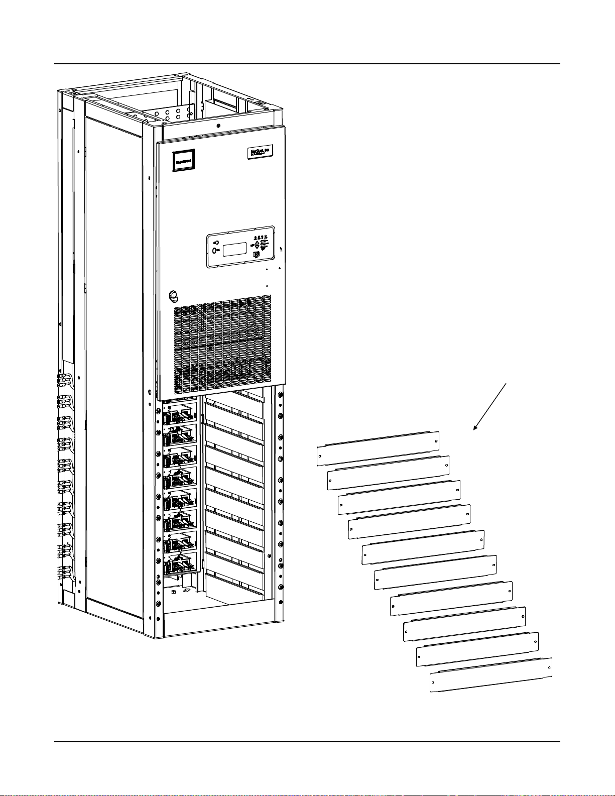
1) Remove all front Rectifier mounting position blank cover panels from each
Power/Distribution Bay to provide access to bay's floor mounting holes and
leveling feet. Cover panels will be re-installed in empty Rectifier mounting
positions after all Rectifiers are installed. To do so: Remove the screws and
ground washers securing the cover panel. Remove the cover panel.
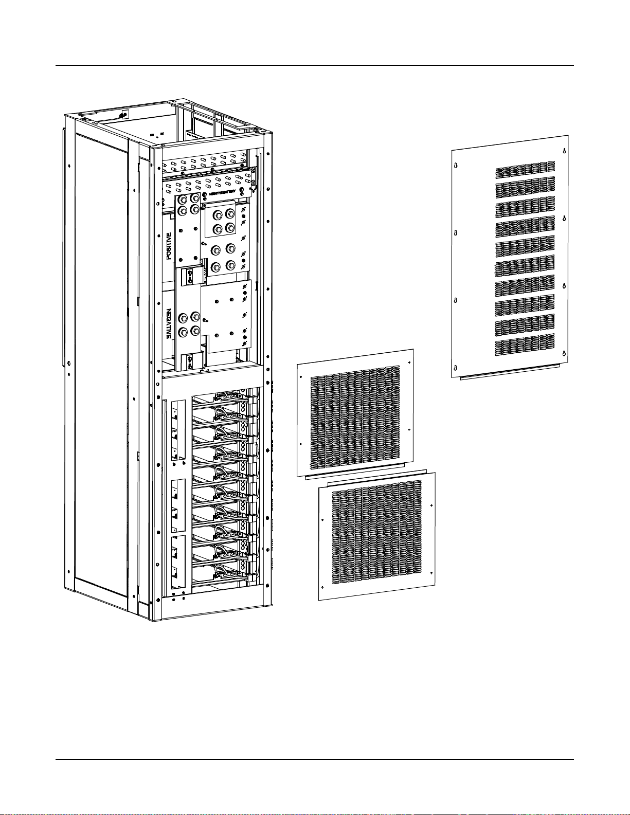
2) Remove the three rear cover panels from each Power/Distribution Bay. These
cover panels will be re-installed after all mounting and electrical connection
procedures have been completed. To do so:
Top Panel: Loosen the screws
securing the cover panel. Lift the cover panel until the screw heads clear the
keyhole slots. Remove the cover panel.
Lower Panels:
Remove the screws and
ground washers securing the panel. Remove the panel.
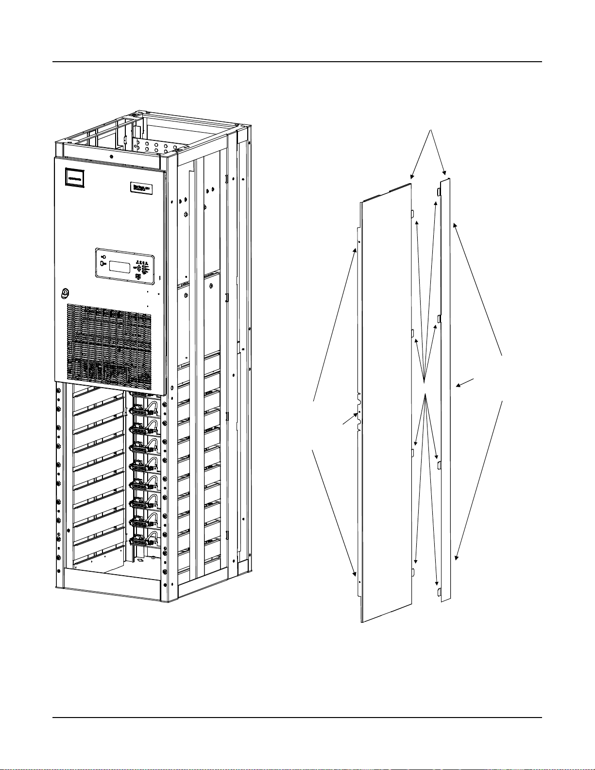
3) Remove the side cover panels from each Power/Distribution Bay (two per side)
as follows, if equipped. Note that you may leave the side cover panels on the
"outside side" of the two end bays.
a) Remove the rear-most side cover panel as follows: Remove the screws
and ground washers securing the side cover panel. Screws are accessible
from the rear of the bay through holes in the side channels. After removing
screws, pivot rear edge of cover panel outward, then slide cover panel
toward rear of bay to disengage tabs at the front of the cover panel from slots
in the bay.
b) Remove the front-most side cover panel as follows: Open the bay's front
door. Remove the screws and ground washers securing the side cover
panel. Screws are accessible from the front of the bay through holes in the
side channels. After removing screws, pivot front edge of cover panel
outward, then slide cover panel toward front of bay to disengage tabs at the
rear of the cover panel from slots in the bay.
Placing and Securing the Bay(s)
1) Place bay(s) in position. Note that clearance holes for 1/4” bolts are provided in
the side rails of each bay. These holes are for bolting the bays together.
2) Level bay(s) as required, using leveling feet in base plate. Adjust leveling feet so
that all bays are even at top, and bolt holes in the side of each bay line up with
holes in the adjacent bay(s).
3) Bolt all bays together. Use 1/4” hardware, six places per pair of bays. Use a
ground washer in two locations with the 1/4" hard w are bolt i ng two bays together.
Chapter 2. Placing the Bays and Installing Internal/External Busbars Page 2-3
This document is property of Emerson Network Power, Energy Systems, North America, Inc. and contains confidential and proprietary information owned by Emerson Network Power, Energy
Systems, North America, Inc. Any copying, use, or disclosure of it without the written permission of Emerson Network Power, Energy Systems, North America, Inc. is strictly prohibited.
Page 18

Section 5876 Installation Instructions
Issue AT, April 26, 2013 Spec. No. 582140000 (Models 802
NLDB, 802NLEB and 802NL-B)
Note: A ground washer is an internal-external tooth, dish-type lock washer.
When installing ground washers, ensure that the ground washer is
oriented so that the teeth dig into the paint on the metal part the ground
washer is secured to (concave side faces the metal part).
4) Install shims between bottom of each bay and the floor as required to distribute
floor loading.
5) Secure bay(s) to floor using fastening hardware per site requirements.
Installing Side Cover Panels on End Bays
1) If the outside sides of the end bays do not have side cover panels, install them
now (two per side). Note that ground washers are used with each screw
securing the side cover panels.
a) Install the rear-most side cover panel as follows: Insert tabs at front of
cover panel into slots in bay. Pivot cover panel into position against side of
bay. Install the previously removed screws and ground washers into cover
panel from rear of bay.
b) Install the front-most side cover panel as follows: Open the bay's front
door. Insert tabs at rear of cover panel into slots in bay. Pivot cover panel
into position against side of bay. Install the previously removed screws and
ground washers into cover panel from front of bay.
Page 2-4 Chapter 2. Placing the Bays and Installing Internal/Extern al Busbars
This document is property of Emerson Network Power, Energy Systems, North America, Inc. and contains confidential and proprietary information owned by Emerson Network Power, Energy
Systems, North America, Inc. Any copying, use, or disclosure of it without the written permission of Emerson Network Power, Energy Systems, North America, Inc. is strictly prohibited.
Page 19

Installation Instructions Section 5876
Spec. No. 582140000 (Models 802
NLDB, 802NLEB and 802NL-B) Issue AT, April 26, 2013
PLACING AND SECURING LIST 2 AND LIST 12 POWER/DISTRIBUTION B AYS (WI TH P DS C)
Note: If you are installing List 1 and List 11 Bays (without List 30, 31, or 32 PDSC), skip
this procedure and refer to “Placing and Securing List 1 and List 11
Power/Distribution Bays (without PDSC)".
• PDSC = AC Input 'Power Distribution Service Cabinet'.
• Refer to Figure 2-1 through Figure 2-9 as this procedure is performed. Figure 2-2
provides a floor hole drilling pattern.
• Bays are typically placed next to each other and bolted together. Refer to the
previous Section, GENERAL REQUIREMENTS, for bay line-up recommendations.
PDSCs are located to the left (as viewed from the front) of each Power/Distribution
Bay.
Procedure
Preparing the Bays and PDSCs
1) Remove all front Rectifier mounting position blank cover panels from each
Power/Distribution Bay to provide access to bay's floor mounting holes and
leveling feet. Cover panels will be re-installed in empty Rectifier mounting
positions after all Rectifiers are installed. To do so: Remove the screws and
ground washers securing the cover panel. Remove the cover panel.
2) Remove the three rear cover panels from each Power/Distribution Bay. These
cover panels will be re-installed after all mounting and electrical connection
procedures have been completed. To do so:
Top Panel: Loosen the screws
securing the cover panel. Lift the cover panel until the screw heads clear the
keyhole slots. Remove the cover panel.
Lower Panels:
Remove the screws and
ground washers securing the panel. Remove the panel.
3) Remove the side cover panels from each Power/Distribution Bay (two per side)
as follows, if equipped. Note that you may leave the side cover panels on the
"outside side" of the right-most (as viewed from the front) end bay.
a) Remove the rear-most side cover panel as follows: Remove the screws
and ground washers securing the side cover panel. Screws are accessible
from the rear of the bay through holes in the side channels. After removing
screws, pivot rear edge of cover panel outward, then slide cover panel
toward rear of bay to disengage tabs at the front of the cover panel from slots
in the bay.
b) Remove the front-most side cover panel as follows: Open the bay's front
door. Remove the screws and ground washers securing the side cover
panel. Screws are accessible from the front of the bay through holes in the
side channels. After removing screws, pivot front edge of cover panel
outward, then slide cover panel toward front of bay to disengage tabs at the
rear of the cover panel from slots in the bay.
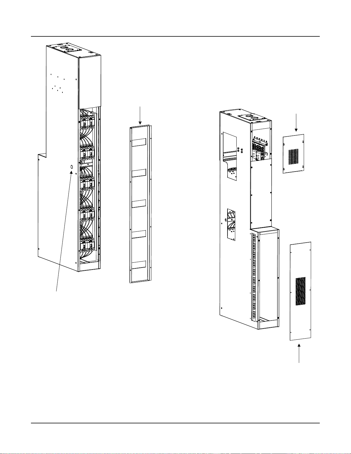
4) Remove the front cover panel from each PDSC. This cover panel will be reinstalled after all mounting and electrical connection procedures have been
completed. To do so: Remove the screws and ground washers securing the
cover panel. Remove the cover panel.
5) Remove the rear lower cover panel from each PDSC. This cover panel will be
re-installed after all mounting and electrical connection procedures have been
completed. To do so: Remove the screws and grou nd wash er s sec uring the
cover panel. Remove the cover panel.
Chapter 2. Placing the Bays and Installing Internal/External Busbars Page 2-5
This document is property of Emerson Network Power, Energy Systems, North America, Inc. and contains confidential and proprietary information owned by Emerson Network Power, Energy
Systems, North America, Inc. Any copying, use, or disclosure of it without the written permission of Emerson Network Power, Energy Systems, North America, Inc. is strictly prohibited.
Page 20

Section 5876 Installation Instructions
Issue AT, April 26, 2013 Spec. No. 582140000 (Models 802
NLDB, 802NLEB and 802NL-B)
6) Remove the rear upper cover panel from each PDSC. This cover panel will be
re-installed after all mounting and electrical connection procedures have been
completed.. To do so: Loosen the screws securing the cover panel. Lift the
cover panel until the screw heads clear the keyhole slots. Remove the cover
panel.
7) Remove the plug-button located on the left side (towards the front) of each
PDSC, except the end PDSC. This opening is provided for data communications
cable routing between bays.
Placing and Securing the Bay(s) and PDSCs
1) Place bay(s) and PDSC(s) in position. Note that PDSCs are placed to the left (as
viewed from the front) of each bay. Note that clearance holes for 1/4” bolts are
provided in the side rails of each bay and PDSC. These holes are for bolting the
bays and PDSCs together.
2) Level bay(s) and PDSC(s) as required, using leveling feet in base plate. Adjust
leveling feet so that all bays and PDSCs are even at top, and bolt holes in the
side of each bay and PDSC line up with holes in the adjacent cabinet(s).
3) Bolt all bays and PDSCs together. Use 1/4” hardware, five places per pair of
cabinets. Use a ground washer in two locations with the 1/4" hardware bolting
two cabinets together.
Note: A ground washer is an internal-external tooth, dish-type lock washer.
When installing ground washers, ensure that the ground washer is
oriented so that the teeth dig into the paint on the metal part the ground
washer is secured to (concave side faces the metal part).
4) Install shims between bottom of each bay and the floor as required to distribute
floor loading.
5) Secure Power/Distribution Bay(s) and PDSC(s) to floor using fastening hardware
per site requirements.
Installing Side Cover Panels on Right-Most End Bay
1) If the outside side of the right-most end bay does not have side cover panels,
install them now (two per side). Note that ground washers are used with each
screw securing the side cover panels.
a) Install the rear-most side cover panel as follows: Insert tabs at front of
cover panel into slots in bay. Pivot cover panel into position against side of
bay. Install the previously removed screws and ground washers into cover
panel from rear of bay.
b) Install the front-most side cover panel as follows: Open the bay's front
door. Insert tabs at rear of cover panel into slots in bay. Pivot cover panel
into position against side of bay. Install the previously removed screws and
ground washers into cover panel from front of bay.
Page 2-6 Chapter 2. Placing the Bays and Installing Internal/Extern al Busbars
This document is property of Emerson Network Power, Energy Systems, North America, Inc. and contains confidential and proprietary information owned by Emerson Network Power, Energy
Systems, North America, Inc. Any copying, use, or disclosure of it without the written permission of Emerson Network Power, Energy Systems, North America, Inc. is strictly prohibited.
Page 21

Installation Instructions Section 5876
Spec. No. 582140000 (Models 802
NLDB, 802NLEB and 802NL-B) Issue AT, April 26, 2013
PLACING AND SECURING LIST 3, 4, 5, 13, 14, AND 15 POWER ONLY BAYS
• Figure 2-1 provides a floor hole drilling pattern.
• Bays are typically placed next to each other and bolted together. Refer to the
previous Section, GENERAL REQUIREMENTS, for bay line-up recommendations.
Procedure
1) Remove all front Rectifier mounting position blank cover panels from each Power
Only Bay to provide access to bay's floor mounting holes and leveling feet.
Cover panels will be re-installed in empt y Rectifier mounti ng pos it ions after all
Rectifiers are installed. To do so: Remove the screws and ground washers
securing the cover panel. Remove the cover panel.
2) Remove the three rear cover panels from each Power Only Bay. These cover
panels will be re-installed after all mounting and electrical connection procedures
have been completed. To do so:
cover panel. Lift the cover panel until the screw heads clear the keyhole slots.
Remove the cover panel.
Lower Panels:
washers securing the panel. Remove the panel.
3) Remove the side cover panels from each Power Only Bay (two per side) as
follows, if equipped. Note that you may leave the side cover panels on the
"outside side" of the two end bays.
Top Panel: Loosen the screws securing the
Remove the screws and ground
a) Remove the rear-most side cover panel as follows: Remove the screws
and ground washers securing the side cover panel. Screws are accessible
from the rear of the bay through holes in the side channels. After removing
screws, pivot rear edge of cover panel outward, then slide cover panel
toward rear of bay to disengage tabs at the front of the cover panel from slots
in the bay.
b) Remove the front-most side cover panel as follows: Open the bay's front
door. Remove the screws and ground washers securing the side cover
panel. Screws are accessible from the front of the bay through holes in the
side channels. After removing screws, pivot front edge of cover panel
outward, then slide cover panel toward front of bay to disengage tabs at the
rear of the cover panel from slots in the bay.
4) Place bay(s) in position. Note that clearance holes for 1/4” bolts are provided in
the side rails of each bay. These holes are for bolting the bays together.
5) Level bay(s) as required, using leveling feet in base plate. Adjust leveling feet so
that all bays are even at top, and bolt holes in the side of each bay line up with
holes in the adjacent bay(s).
6) Bolt all bays together. Use 1/4” hardware, six places per pair of bays. Use a
ground washer in two locations with the 1/4" hardware bolting two bays together.
Note: A ground washer is an inter nal-external tooth, dish-type lock washer.
When installing ground washers, ensure that the ground washer is
oriented so that the teeth dig into the paint on the metal part the ground
washer is secured to (concave side faces the metal part).
7) Install shims between bottom of each bay and the floor as required to distribute
floor loading.
8) Secure bay(s) to floor using fastening hardware per site requirements.
Chapter 2. Placing the Bays and Installing Internal/External Busbars Page 2-7
This document is property of Emerson Network Power, Energy Systems, North America, Inc. and contains confidential and proprietary information owned by Emerson Network Power, Energy
Systems, North America, Inc. Any copying, use, or disclosure of it without the written permission of Emerson Network Power, Energy Systems, North America, Inc. is strictly prohibited.
Page 22

Section 5876 Installation Instructions
Issue AT, April 26, 2013 Spec. No. 582140000 (Models 802
NLDB, 802NLEB and 802NL-B)
9) If the outside sides of the end bays do not have side cover panels, install them
now (two per side). Note that ground washers are used with each screw
securing the side cover panels.
a) Install the rear-most side cover panel as follows: Insert tabs at front of
cover panel into slots in bay. Pivot cover panel into position against side of
bay. Install the previously removed screws and ground washers into cover
panel from rear of bay.
b) Install the front-most side cover panel as follows: Open the bay's front
door. Insert tabs at rear of cover panel into slots in bay. Pivot cover panel
into position against side of bay. Install the previously removed screws and
ground washers into cover panel from front of bay.
Page 2-8 Chapter 2. Placing the Bays and Installing Internal/Extern al Busbars
This document is property of Emerson Network Power, Energy Systems, North America, Inc. and contains confidential and proprietary information owned by Emerson Network Power, Energy
Systems, North America, Inc. Any copying, use, or disclosure of it without the written permission of Emerson Network Power, Energy Systems, North America, Inc. is strictly prohibited.
Page 23

Installation Instructions Section 5876
Spec. No. 582140000 (Models 802
NLDB, 802NLEB and 802NL-B) Issue AT, April 26, 2013
PLACING AND SECURING LIST 16 DISTRIBUTION ONLY BAYS
• Figure 2-3 provides List 16 Distribution Only Bay hole drilling patterns.
• Bays are typically placed next to each other and bolted together. Refer to the
previous Section, GENERAL REQUIREMENTS, for bay line-up recommendations.
Procedure
1) If bays are to be placed next to each other, remove the side cover panels from
the sides that will be placed next to another bay (leaving the side cover panels on
the "outside side" of the two end bays). Install side cover panels on end bays as
required.
2) Place bay(s) in position. Note that clearance holes for 1/4” bolts are provided in
the side rails of each bay. These holes are for bolting the bays together.
3) Remove the lower rear cover panel from each bay to provide access to bay's
floor mounting holes. These cover panels will be re-installed after all mounting
and electrical connection procedures have been completed.
4) Level bay(s) as required, using the leveling nut provided in base plate. Adjust
leveling bolts so that all bays are even at top, and bolt holes in the side of each
bay line up with holes in the adjacent bay(s).
5) Bolt all bays together. Use 1/4” hardware, seven places per pair of bays. Use a
ground washer in two locations with the 1/4" hardware bolting two bays together.
Note: A ground washer is an internal-external tooth, dish-type lock washer.
When installing ground washers, ensure that the ground washer is
oriented so that the teeth dig into the paint on the metal part the ground
washer is secured to (concave side faces the metal part).
6) Install shims between bottom of each bay and the floor as required to distribute
floor loading.
7) Secure bay(s) to floor using fastening hardware per site requirements.
8) If the outside sides of the end bays do not have side cover panels, install them
now (two per side). Note that ground washers are used with each screw
securing the side cover panels.
Chapter 2. Placing the Bays and Installing Internal/External Busbars Page 2-9
This document is property of Emerson Network Power, Energy Systems, North America, Inc. and contains confidential and proprietary information owned by Emerson Network Power, Energy
Systems, North America, Inc. Any copying, use, or disclosure of it without the written permission of Emerson Network Power, Energy Systems, North America, Inc. is strictly prohibited.
Page 24
Section 5876 Installation Instructions
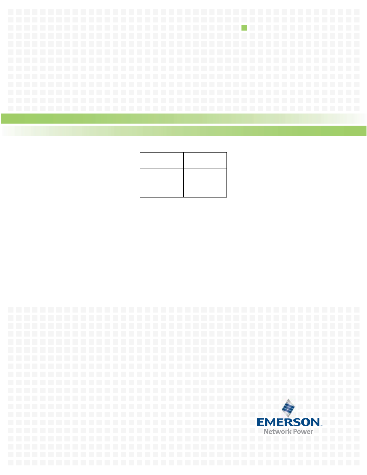
0.750 X 2.000 SLOT
Issue AT, April 26, 2013 Spec. No. 582140000 (Models 802
NLDB, 802NLEB and 802NL-B)
2.19
FRONT
(4 PLACES)
3/8-16 Floor
Leveling Bolts
19.62
24.00
3.44
30.00
24.12
2.44
2.19
Floor Hole Drilling Pattern
Power/Distribution Bay
Figure 2-1
Floor Mounting Hole Dimensions
(Primary and Secondary Power/Distribution Bays without PDSC)
(Power Only Bays Have the Same Hole Pattern)
(all dimensions in inches)
Page 2-10 Chapter 2. Placing the Bays and Installing Internal/External Busbars
This document is property of Emerson Network Power, Energy Systems, North America, Inc. and contains confidential and proprietary information owned by Emerson Network Power, Energy
Systems, North America, Inc. Any copying, use, or disclosure of it without the written permission of Emerson Network Power, Energy Systems, North America, Inc. is strictly prohibited.
Page 25
Installation Instructions Section 5876
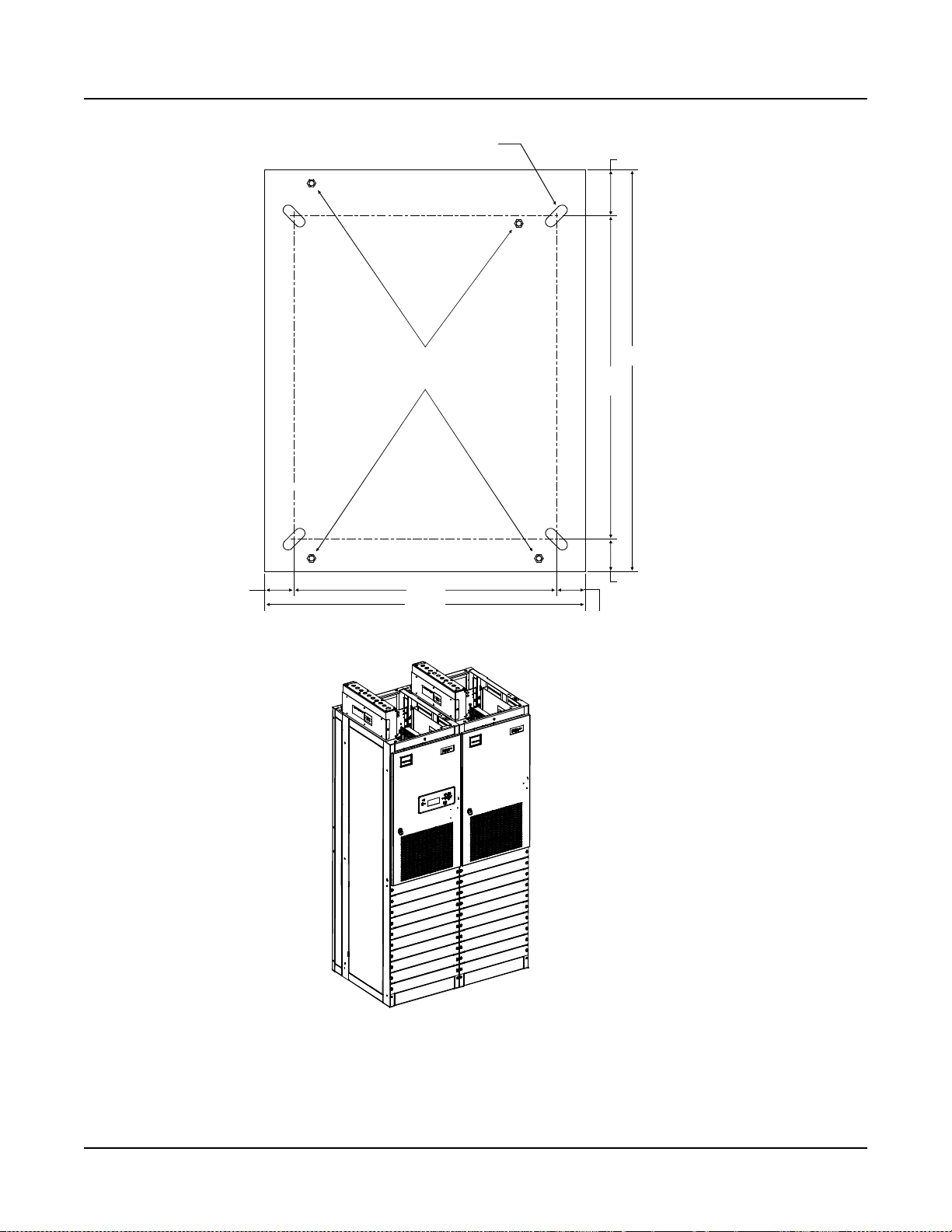
3/8-16 Floor
Leveling Bolts
FRONT
19.62
24.00
2.19
24.12
30.00
2.44
3.44
0.750 X 2.000 SLOT
(4 PLACES)
2.19
9.85
5.63
2.11
2.11
POWER/
DISTRIBUTION BAY
AC POWER
DISTRIBUTION
SERVICE CABINET
0.750 X 2.000 SLOT
(4 PLACES)
3/8-16
Floor
Leveling
Bolts
Floor Hole Drilling Pattern
Power/Distribution Bay
and PDSC
Spec. No. 582140000 (Models 802
NLDB, 802NLEB and 802NL-B) Issue AT, April 26, 2013
Figure 2-2
Floor Mounting Hole Dimensions
Primary and Secondary Power/ Distr i but ion Bays with PDSC
(all dimensions in inches)
Chapter 2. Placing the Bays and Installing Internal/External Busbars Page 2-11
This document is property of Emerson Network Power, Energy Systems, North America, Inc. and contains confidential and proprietary information owned by Emerson Network Power, Energy
Systems, North America, Inc. Any copying, use, or disclosure of it without the written permission of Emerson Network Power, Energy Systems, North America, Inc. is strictly prohibited.
Page 26
Section 5876 Installation Instructions
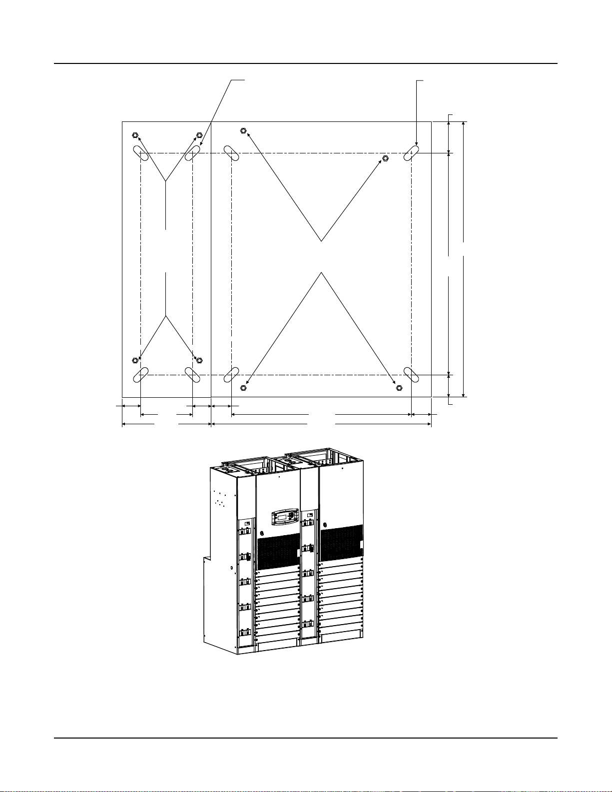
Front
3/8-16
Welded Nut (4)
0.812 Dia.
(8 PLACES)
25.875
23.250
27.625
25.375
19.500
26.625
24.000
3.063
1.750
1.875
2.750
4.063
30.000
31.375
19.500
5.937
Issue AT, April 26, 2013 Spec. No. 582140000 (Models 802
NLDB, 802NLEB and 802NL-B)
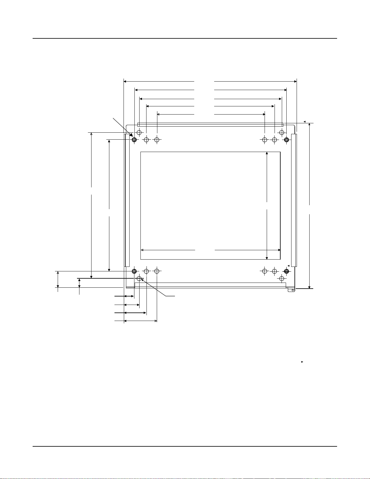
Figure 2-3
Floor Mounting Hole Dimensions - Distribution Only Bay
(all dimensions in inches)
Page 2-12 Chapter 2. Placing the Bays and Installing Internal/External Busbars
This document is property of Emerson Network Power, Energy Systems, North America, Inc. and contains confidential and proprietary information owned by Emerson Network Power, Energy
Systems, North America, Inc. Any copying, use, or disclosure of it without the written permission of Emerson Network Power, Energy Systems, North America, Inc. is strictly prohibited.
Page 27
Installation Instructions Section 5876
PCU Mounting Posi
tion
Blank Cover Panels
Spec. No. 582140000 (Models 802
NLDB, 802NLEB and 802NL-B) Issue AT, April 26, 2013
Figure 2-4
Removing Rectifier Mounting Position Blank Cover Panels from Power/Distribution Bay
Chapter 2. Placing the Bays and Installing Internal/External Busbars Page 2-13
This document is property of Emerson Network Power, Energy Systems, North America, Inc. and contains confidential and proprietary information owned by Emerson Network Power, Energy
Systems, North America, Inc. Any copying, use, or disclosure of it without the written permission of Emerson Network Power, Energy Systems, North America, Inc. is strictly prohibited.
Page 28
Section 5876 Installation Instructions
Rear
Cover
Panels
Issue AT, April 26, 2013 Spec. No. 582140000 (Models 802
NLDB, 802NLEB and 802NL-B)
Figure 2-5
Removing Rear Cover Panels from Power/Distribution Bay
Page 2-14 Chapter 2. Placing the Bays and Installing Internal/External Busbars
This document is property of Emerson Network Power, Energy Systems, North America, Inc. and contains confidential and proprietary information owned by Emerson Network Power, Energy
Systems, North America, Inc. Any copying, use, or disclosure of it without the written permission of Emerson Network Power, Energy Systems, North America, Inc. is strictly prohibited.
Page 29
Installation Instructions Section 5876
Remove/Install
Screws through
Rear of Bay at
these Points
Side
Cover
Panels
TABS
Remove/Install
Screws through
Front of Bay at
these Points
Spec. No. 582140000 (Models 802
NLDB, 802NLEB and 802NL-B) Issue AT, April 26, 2013
Figure 2-6
Removing Side Cover Panels from Po wer /Distributio n Bay
Chapter 2. Placing the Bays and Installing Internal/External Busbars Page 2-15
This document is property of Emerson Network Power, Energy Systems, North America, Inc. and contains confidential and proprietary information owned by Emerson Network Power, Energy
Systems, North America, Inc. Any copying, use, or disclosure of it without the written permission of Emerson Network Power, Energy Systems, North America, Inc. is strictly prohibited.
Page 30
Section 5876 Installation Instructions
Front
Cover
Panel Rear Upper
Cover Panel
Rear Lower
Cover Panel
Remove Plug-Button
on all but End Cabinet
Issue AT, April 26, 2013 Spec. No. 582140000 (Models 802
NLDB, 802NLEB and 802NL-B)
Page 2-16 Chapter 2. Placing the Bays and Installing Internal/External Busbars
This document is property of Emerson Network Power, Energy Systems, North America, Inc. and contains confidential and proprietary information owned by Emerson Network Power, Energy
Systems, North America, Inc. Any copying, use, or disclosure of it without the written permission of Emerson Network Power, Energy Systems, North America, Inc. is strictly prohibited.
Figure 2-7
Removing Front and Rear Cover Panels, and Plug-Button
from PDSC (AC Input 'Power Distribution Service Cabinet')
Page 31

Installation Instructions Section 5876
Hardware Build-Up: (use ground washers
in ce
nter tie points each side)
Bolt
, Ground Washer, Bay/Cabinet
Sides,
Ground Washer, Nut
Hardware Build-Up: (use in remain
ing connection points)
Bolt, L
ock Washer, Flat Washer, Bay/C
abinet Sides,
Flat Washer, Lo
ck Washer, Nut
Bay/Cabinet S
ides Bay/Cabinet Sides
Holes for Bolting
Power/Distribution
Bays a
nd PDSCs
Togethrer
Spec. No. 582140000 (Models 802
NLDB, 802NLEB and 802NL-B) Issue AT, April 26, 2013
Chapter 2. Placing the Bays and Installing Internal/External Busbars Page 2-17
This document is property of Emerson Network Power, Energy Systems, North America, Inc. and contains confidential and proprietary information owned by Emerson Network Power, Energy
Systems, North America, Inc. Any copying, use, or disclosure of it without the written permission of Emerson Network Power, Energy Systems, North America, Inc. is strictly prohibited.
Figure 2-8
Bolting Power/Distribut ion Bay to PDSC Cabinet
Page 32

Section 5876 Installation Instructions
Hardware Build-Up: (use ground washers
in center tie points each side)
Bolt, Ground Washer, Bay/Cabinet Sides,
Ground Washer, Nut
Hardware Build-Up: (use in remaining connection points)
Bolt, Lock Washer,Flat Washer, Bay/Cabinet Sides,
Flat Washer, Lock Washer, Nut
Bay/Bay Sides Bay/Bay Sides
Holes for Bolting
Power/Distribution
Bays Togethrer
Issue AT, April 26, 2013 Spec. No. 582140000 (Models 802
NLDB, 802NLEB and 802NL-B)
Figure 2-9
Bolting Power/Distribut ion Bay to Power/Distribution Bay
Page 2-18 Chapter 2. Placing the Bays and Installing Internal/External Busbars
This document is property of Emerson Network Power, Energy Systems, North America, Inc. and contains confidential and proprietary information owned by Emerson Network Power, Energy
Systems, North America, Inc. Any copying, use, or disclosure of it without the written permission of Emerson Network Power, Energy Systems, North America, Inc. is strictly prohibited.
Page 33

Installation Instructions Section 5876
Spec. No. 582140000 (Models 802
NLDB, 802NLEB and 802NL-B) Issue AT, April 26, 2013
INSTALLING POWER/DISTRIBUTION BAY TO POWER/DISTRIBUTION B AY NEGATIVE AND POSITIVE BUSBAR LINKS
Note: Refer to the next procedure to connect the newer style bay to an existing older
style bay.
Note: Apply electrical anti-oxidation compound to mating surfaces of busbars before
connecting together.
Procedure
1) Refer to Figure 2-10 or Figure 2-11 and install the "Negative Busbar Link"
between the "Negative Side" of one bay and the "Negative Side" of the adjacent
bay. Use the supplied 3/8-16 x 1-1/2" bolts and hardware. Hardware build-up is :
Bolt, Belleville Lock Washer, Belleville Lock Washer (concave side of Belleville
lock washers face each other), Hardened Flat Washer. Torque to 180 in-lbs.
2) Refer to Figure 2-10 or Figure 2-11 and install the "Positive Busbar Link "
between the "Positive Side" of one bay and the "Positive Side" of the adjacent
bay. Use the supplied 3/8-16 x 1-1/2" bolts and hardware. Hardware build-up is :
Bolt, Belleville Lock Washer, Belleville Lock Washer (concave side of Belleville
lock washers face each other), Hardened Flat Washer. Torque to 180 in-lbs.
3) For bays with PDSCs, the busbar link cover shield is installed after all mounting
and electrical connection procedures are completed.
4) Repeat these steps for each adjacent bay.
Chapter 2. Placing the Bays and Installing Internal/External Busbars Page 2-19
This document is property of Emerson Network Power, Energy Systems, North America, Inc. and contains confidential and proprietary information owned by Emerson Network Power, Energy
Systems, North America, Inc. Any copying, use, or disclosure of it without the written permission of Emerson Network Power, Energy Systems, North America, Inc. is strictly prohibited.
Page 34

Section 5876 Installation Instructions
3/8-16 x 1-1/2" Bolt
3/8" Belleville Lock Washer
3/8" Belleville Lock Washer
(concave side of Belleville
Lock Washers face each other)
3/8” Hardened Flat Washer
(10 Places per Busbar)
POSITIVE
BUSBAR LINK
NEGATIVE
BUSBAR LINK
Slide Busbar Links Under
Bays' Upright Channels.
Use Bolt Holes as Shown
in Illustration.
Torque to 180 in-lbs.
Issue AT, April 26, 2013 Spec. No. 582140000 (Models 802
NLDB, 802NLEB and 802NL-B)
Figure 2-10
Installing Power/Distribution Bay to Power/Distribution Bay Negative and Positive Busbar Links
(Lists 1 and 11)
Page 2-20 Chapter 2. Placing the Bays and Installing Internal/External Busbars
This document is property of Emerson Network Power, Energy Systems, North America, Inc. and contains confidential and proprietary information owned by Emerson Network Power, Energy
Systems, North America, Inc. Any copying, use, or disclosure of it without the written permission of Emerson Network Power, Energy Systems, North America, Inc. is strictly prohibited.
Page 35

Installation Instructions Section 5876
Spec. No. 582140000 (Models 802
NLDB, 802NLEB and 802NL-B) Issue AT, April 26, 2013
POSITIVE
BUSBAR LINK
3/8-16 x 1-1/2" Bolt
3/8" Belleville Lock Washer
3/8" Belleville Lock Washer
(concave side of Belleville
Lock Washers face each other)
3/8” Hardened Flat Washer
(10 Places per Busbar)
NEGATIVE
BUSBAR LINK
Slide Busbar Links Under
Bays' Upright Channels.
Use Bolt Holes as Shown
in Illustration.
Torque to 180 in-lbs.
(installed after
and electrical
are completed)
Busbar Link
Cover Shield
all mounting
connection
procedures
Figure 2-11
Installing Power/Distribution Bay to Power/Distribution Bay Negative and Positive Busbar Links
(Lists 2 and 12, w/ List 30 or 31)
Chapter 2. Placing the Bays and Installing Internal/External Busbars Page 2-21
This document is property of Emerson Network Power, Energy Systems, North America, Inc. and contains confidential and proprietary information owned by Emerson Network Power, Energy
Systems, North America, Inc. Any copying, use, or disclosure of it without the written permission of Emerson Network Power, Energy Systems, North America, Inc. is strictly prohibited.
Page 36

Section 5876 Installation Instructions
Issue AT, April 26, 2013 Spec. No. 582140000 (Models 802
NLDB, 802NLEB and 802NL-B)
INSTALLING POWER/DISTRIBUTION BAY TO POWER/DISTRIBUTION B AY NEGATIVE AND POSITIVE BUSBAR LINKS (NEWER STYLE BAY TO AN EXISTING OLDER STYLE BAY)
Note: Apply electrical anti-oxidation compound to mating surfaces of busbars before
connecting together.
Procedure
1) Refer to Figure 2-12 and install the "Negati ve Busbar Link " betwee n the
"Negative Side" of one bay and the "Negative Side" of the adjacent bay. Use the
supplied 3/8-16 x 1-1/2" bolts and hardware. Hardware build-up is: Bolt,
Belleville Lock Washer, Belleville Lock Washer (concave side of Belleville lock
washers face each other), Hardened Flat Washer. Torque to 180 in-lbs.
2) Refer to Figure 2-12 and install the "Positive Busbar Link " between the "P os itive
Side" of one bay and the "Positive Side" of the adjacent bay. Use the supplied
3/8-16 x 1-1/2" bolts and hardware. Hardware build-up is: Bolt, Belleville Lock
Washer, Belleville Lock Washer (concave side of Belleville lock washers face
each other), Hardened Flat Washer. Torque to 180 in-lbs.
3) For bays with PDSCs, the busbar link cover shield is installed after all mounting
and electrical connection procedures are completed.
4) Repeat these steps for each adjacent bay.
Page 2-22 Chapter 2. Placing the Bays and Installing Internal/External Busbars
This document is property of Emerson Network Power, Energy Systems, North America, Inc. and contains confidential and proprietary information owned by Emerson Network Power, Energy
Systems, North America, Inc. Any copying, use, or disclosure of it without the written permission of Emerson Network Power, Energy Systems, North America, Inc. is strictly prohibited.
Page 37

Installation Instructions Section 5876
Newer
Spec. No. 582140000 (Models 802
NLDB, 802NLEB and 802NL-B) Issue AT, April 26, 2013
Newer
Style Bay
Existing Older
Style Bay
Style Bay
Existing Older
Style Bay
POSITIVE
BUSBAR LINK
3/8-16 x 1-1/2" Bolt
3/8" Belleville Lock Washer
3/8" Belleville Lock Washer
(concave side of Belleville
Lock Washers face each other)
3/8” Hardened Flat Washer
NEGATIVE
BUSBAR LINK
Newer Style Bay side,
use bolt holes as
Existing Older Style Bay
side, use ALL bolt holes.
shown in illustration.
Slide Busbar Links Under
Bays' Upright Channels.
Torque to 180 in-lbs.
List 1 and 11 shown.
List 2 and 12 w/ List 30 or 31 similar.
Figure 2-12
Installing Power/Distribution Bay to Power/Distribution Bay Negative and Positive Busbar Links
(Newer Style Bay Connected to an Existing Older Style Bay
Chapter 2. Placing the Bays and Installing Internal/External Busbars Page 2-23
This document is property of Emerson Network Power, Energy Systems, North America, Inc. and contains confidential and proprietary information owned by Emerson Network Power, Energy
Systems, North America, Inc. Any copying, use, or disclosure of it without the written permission of Emerson Network Power, Energy Systems, North America, Inc. is strictly prohibited.
Page 38

Section 5876 Installation Instructions
Power/Distribution
Bay
Power/Distribution
Bay
PDSC
PDSC
Row of PDSC PCU
AC Input Connectors
Connectors
in PDSC
to
PCU Mtg.
Pos. #1
to
PCU Mtg.
Pos. #2
to
PCU Mtg.
Pos. #3
to
PCU Mtg.
Pos. #4
to
PCU Mtg.
Pos. #5
to
PCU Mtg.
Pos. #6
to
PCU Mtg.
Pos. #7
to
PCU Mtg.
Pos. #8
to
PCU Mtg.
Pos. #9
to
PCU Mtg.
Pos. #10
Torque to
23 in-lbs.
A
B
C
A
B
C
A
B
C
A
B
C
A
B
C
A
B
C
A
B
C
A
B
C
A
B
C
A
B
C
Row of PCU Mtg. Pos.
AC Input Connectors
Issue AT, April 26, 2013 Spec. No. 582140000 (Models 802
NLDB, 802NLEB and 802NL-B)
CONNECTING POWER/DISTRIBUTION BAY RECTIFIER MOUNTING POSITION AC INPUT CONNECTORS TO PDSC (LISTS 2 AND 12 ONLY)
Procedure
1) Refer to Figure 2-13, and feed the wires from the Rectifier Mounting Position AC
Input Connectors located in a Power/Distribution Bay through the side of the
Rectifier Mounting Position AC Input Cover and into the PDSC. Connect the
wires to the appropriate connectors provided in the PDSC. Observe the labels
on the wires (A, B, C). Torque each connection to 23 in-lbs.
2) Repeat this step for each bay.
Page 2-24 Chapter 2. Placing the Bays and Installing Internal/External Busbars
This document is property of Emerson Network Power, Energy Systems, North America, Inc. and contains confidential and proprietary information owned by Emerson Network Power, Energy
Systems, North America, Inc. Any copying, use, or disclosure of it without the written permission of Emerson Network Power, Energy Systems, North America, Inc. is strictly prohibited.
Connecting Rectifier Mounting Position AC Input Connectors to PDSC (Lists 2 and 12 Only)
Figure 2-13
Page 39

Installation Instructions Section 5876
Spec. No. 582140000 (Models 802
NLDB, 802NLEB and 802NL-B) Issue AT, April 26, 2013
INSTALLING POWER/DISTRIBUTION BAY EXTERNAL TOPMOUNT HORIZONTAL BATTERY INPUT BUSBAR ASSEMBLY,
P/N 554873 (IF FURNISHED)
Tools and Material Required to Install the Busbar Assembly
a) 9/16" Wrench (for 3/8" Hardware)
b) 15/16" Wrench (for 5/8" Hardware)
c) Channel Locks
d) Anti-Oxidation Compound
e) Torque Wrench
Installation Procedure
Danger: Before performing this procedure, ensure that the Power/Distribution Bay
is COMPLETELY DISCONNECTED from all power sources.
Note: Apply electrical anti-oxidation compound to mating surfaces of busbars before
connecting together.
Assemble the Busbar Kit to the top of the bays as shown in Figure 2-14 through Figure
2-21. Refer to Figure 2-21
for an assembled view.
Chapter 2. Placing the Bays and Installing Internal/External Busbars Page 2-25
This document is property of Emerson Network Power, Energy Systems, North America, Inc. and contains confidential and proprietary information owned by Emerson Network Power, Energy
Systems, North America, Inc. Any copying, use, or disclosure of it without the written permission of Emerson Network Power, Energy Systems, North America, Inc. is strictly prohibited.
Page 40

Section 5876 Installation Instructions
STEP 1
Install “Main Positive Busbar” onto Bay’s
Positive Busbar. Hand-tighten hardware.
(1) Main Positive Busbar, P/N 554877
Note:Apply Electrical Anti-Oxidation Compound
to Busbar Mating Surfaces.
(12) 3/8” Flat Washer, P/N 214204100
(12) 3/8” Belleville Washer,P/N 214825000
(12) 3/8-16 Hex Nut, P/N 228567100
Hand-tighten.
Note: Concave Side of Belleville Washer Faces
Busbar, Convex Side Faces Hex Nut.
Belleville Washer install between Hex Nut
and Flat Washer
.
Rear Top
of Bay
Assembled
View
Do the following first before assembly:
1. Remove 552402 (1) and 116638 (4) from Bay.
2. Mount 554880 to the 554877 with 116638 (3).
Issue AT, April 26, 2013 Spec. No. 582140000 (Models 802
NLDB, 802NLEB and 802NL-B)
Figure 2-14
Power/Distribution Ba y Ext ernal Top-Mount Horizontal Busbar Assembly (P/N 554873)
Assembly Procedure Step 1
Page 2-26 Chapter 2. Placing the Bays and Installing Internal/External Busbars
This document is property of Emerson Network Power, Energy Systems, North America, Inc. and contains confidential and proprietary information owned by Emerson Network Power, Energy
Systems, North America, Inc. Any copying, use, or disclosure of it without the written permission of Emerson Network Power, Energy Systems, North America, Inc. is strictly prohibited.
Page 41

Installation Instructions Section 5876
Assembled
View
STEP 2
Install “Support Bar” and “Related
Hardware” onto Top of Bay.
(2) Threaded Insulator, P/N 245857200 Torque to 715 In-lbs.
(2) Support Bar Clip, P/N 351322300
(2) Support Bar, P/N 237790100
(2) 5/8” Lock Washer, P/N 215111800
(2) 5/8” Hex Nut, P/N 228580900 Leave 1/4” Space Between
Bottom of Nut and Top of Bay.
(2) 5/8-11 x 7” Threaded Rod, P/N 334317000
(2) Support Bar Clip, P/N 351322300
Rear Top
of Bay
Spec. No. 582140000 (Models 802
NLDB, 802NLEB and 802NL-B) Issue AT, April 26, 2013
Figure 2-15
Power/Distribution Ba y Ext ernal Top-Mount Horizontal Busbar Assembly (P/N 554873)
Assembly Procedure Step 2
Chapter 2. Placing the Bays and Installing Internal/External Busbars Page 2-27
This document is property of Emerson Network Power, Energy Systems, North America, Inc. and contains confidential and proprietary information owned by Emerson Network Power, Energy
Systems, North America, Inc. Any copying, use, or disclosure of it without the written permission of Emerson Network Power, Energy Systems, North America, Inc. is strictly prohibited.
Page 42

Section 5876 Installation Instructions
Issue AT, April 26, 2013 Spec. No. 582140000 (Models 802
NLDB, 802NLEB and 802NL-B)
STEP 3
Install “Main Negative Busbar” onto Bay’s
Negative Busbar. Hand-tighten hardware.
(1) Main Negative Busbar,P/N554875
Note:ApplyElectricalAnti-Oxidation Compound
to Busbar Mating Surfaces.
(8) 3/8” Flat Washer, P/N 214204100
(8) 3/8” Belleville Washer, P/N 214825000
(8) 3/8-16 Hex Nut, P/N 228567100 Hand-Tighten
Note: Concave Side of Belleville Washer Faces
Busbar,ConvexSideFacesHex Nut.
Belleville Washer Install between Hext Nut
and Flat Washer.
Mount 554876 to the 554875.
Hardware:
214204100 (4)
214825000 (4)
228567100 (4)
Assembled
View
Rear Top
of Bay
Figure 2-16
Power/Distribution Ba y Ext ernal Top-Mount Horizontal Busbar Assembly (P/N 554873)
Assembly Procedure Step 3
Page 2-28 Chapter 2. Placing the Bays and Installing Internal/External Busbars
This document is property of Emerson Network Power, Energy Systems, North America, Inc. and contains confidential and proprietary information owned by Emerson Network Power, Energy
Systems, North America, Inc. Any copying, use, or disclosure of it without the written permission of Emerson Network Power, Energy Systems, North America, Inc. is strictly prohibited.
Page 43

Installation Instructions Section 5876
Note: Concave Side of Belleville Washer Faces
Busbar, Convex Side Faces Bolt Head.
Belleville Washer install between Bolt Head
and Flat Washer.
(1) Horizontal Landing Negative Busbar, P/N 514434
Note: Apply ElectricalAnti-Oxidation Compound
to Busbar Mating Surfaces.
(6) 3/8” Belleville Washer, P/N 214825000
(6) 3/8-16 x 1-1/4” Bolt, P/N 227646800
(6) 3/8" Flat Washer, P/N 214204100
Assembled
View
Rear Top
of Bay
STEP 4
Install “Horizontal Landing Negative Busbar”
onto “Main Negative Busbar”.
Torque to 180 in-lbs.
Spec. No. 582140000 (Models 802
NLDB, 802NLEB and 802NL-B) Issue AT, April 26, 2013
Figure 2-17
Power/Distribution Ba y Ext ernal Top-Mount Horizontal Busbar Assembly (P/N 554873)
Assembly Procedure Step 4
Chapter 2. Placing the Bays and Installing Internal/External Busbars Page 2-29
This document is property of Emerson Network Power, Energy Systems, North America, Inc. and contains confidential and proprietary information owned by Emerson Network Power, Energy
Systems, North America, Inc. Any copying, use, or disclosure of it without the written permission of Emerson Network Power, Energy Systems, North America, Inc. is strictly prohibited.
Page 44

Section 5876 Installation Instructions
STEP 5
Install "Threaded Insulators" onto
"Horizontal Landing Negative Busbar".
(2) Threaded Insulator, P/N 245857200
(2) 5/8-11 x 1-1/4" Threaded Rod, P/N 334315700
(2) Threaded Insulator, P/N 245857200
(2) 5/8-11 x 1-1/2"Threaded Rod, P/N 334315900
Hand-Tighten
Hand-Tighten
Assembled
View
Rear Top
of Bay
Issue AT, April 26, 2013 Spec. No. 582140000 (Models 802
NLDB, 802NLEB and 802NL-B)
Figure 2-18
Power/Distribution Ba y Ext ernal Top-Mount Horizontal Busbar Assembly (P/N 554873)
Assembly Procedure Step 5
Page 2-30 Chapter 2. Placing the Bays and Installing Internal/External Busbars
This document is property of Emerson Network Power, Energy Systems, North America, Inc. and contains confidential and proprietary information owned by Emerson Network Power, Energy
Systems, North America, Inc. Any copying, use, or disclosure of it without the written permission of Emerson Network Power, Energy Systems, North America, Inc. is strictly prohibited.
Page 45

Installation Instructions Section 5876
STEP 6
Install "Horizontal Landing Positive Busbar"
onto "Main Positive Busbar".
(2) 5/8-11 x 1" Bolt, P/N 227655100
(2) 5/8" Lock Washer, P/N 215111800
(2) 5/8" Flat Washer, P/N 214201300
Torque to 715 in-lbs.
(1) Horizontal Landing Positive Busbar, P/N 514436
Note: Apply Electrical Anti-Oxidation Compound
to Busbar Mating Surfaces.
(6) 3/8" Flat Washer, P/N 214204100
(6) 3/8" Belleville Washer, P/N 214825000
(6) 3/8-16 x 1-1/4" Bolt, P/N 227646800
Torque to 180 in-l
bs.
Note: Concave Side of Belleville Washer Faces
Busbar, Convex Side Faces Bolt Head.
Belleville Washer install between Bolt Head
and Flat Washer.
Assembled
View
Rear Top
of Bay
Spec. No. 582140000 (Models 802
NLDB, 802NLEB and 802NL-B) Issue AT, April 26, 2013
Figure 2-19
Power/Distribution Ba y Ext ernal Top-Mount Horizontal Busbar Assembly (P/N 554873)
Assembly Procedure Step 6
Chapter 2. Placing the Bays and Installing Internal/External Busbars Page 2-31
This document is property of Emerson Network Power, Energy Systems, North America, Inc. and contains confidential and proprietary information owned by Emerson Network Power, Energy
Systems, North America, Inc. Any copying, use, or disclosure of it without the written permission of Emerson Network Power, Energy Systems, North America, Inc. is strictly prohibited.
Page 46

Section 5876 Installation Instructions
Torque these c
onnections
to 180 in-lbs (20 pl
aces).
Rear Top
of Bay
STEP 7
Final Torque
Issue AT, April 26, 2013 Spec. No. 582140000 (Models 802
NLDB, 802NLEB and 802NL-B)
Figure 2-20
Power/Distribution Ba y Ext ernal Top-Mount Horizontal Busbar Assembly (P/N 554873)
Assembly Procedure Step 7
Page 2-32 Chapter 2. Placing the Bays and Installing Internal/External Busbars
This document is property of Emerson Network Power, Energy Systems, North America, Inc. and contains confidential and proprietary information owned by Emerson Network Power, Energy
Systems, North America, Inc. Any copying, use, or disclosure of it without the written permission of Emerson Network Power, Energy Systems, North America, Inc. is strictly prohibited.
Page 47

Installation Instructions Section 5876
Spec. No. 582140000 (Models 802
NLDB, 802NLEB and 802NL-B) Issue AT, April 26, 2013
Assembled View from Rear of Bay
Assembled View from Front of Bay
Figure 2-21
Power/Distribution Ba y Ext ernal Top-Mount Horizontal Busbar Assembly (P/N 554873)
Assembled Views
Chapter 2. Placing the Bays and Installing Internal/External Busbars Page 2-33
This document is property of Emerson Network Power, Energy Systems, North America, Inc. and contains confidential and proprietary information owned by Emerson Network Power, Energy
Systems, North America, Inc. Any copying, use, or disclosure of it without the written permission of Emerson Network Power, Energy Systems, North America, Inc. is strictly prohibited.
Page 48

Section 5876 Installation Instructions
P/N 554873
Busbar Assembly
Torque to 143 in-lbs.
3/8-16 x 5/8" Bolt, P/N 227646500 (one per side)
3/8" Lock Washer, P/N 215111300 (one per side)
3/8" Flat Washer,P/N 214112100(one per side)
(support bar)
Insulator, P/N 245857100 (one per side)
Busbar Shield, P/N 528481
Note: Place Flap on Shield over Support Bar
(see assembled views)
3/8" Flat Washer,P/N 214112100 (one per side)
3/8" Lock Washer,P/N 215111300 (one per side)
3/8-16 x 7/8" Bolt, P/N 227646700 (one per side)
Torque to 143 in-lbs.
P/N 528482
Busbar
Shield
Kit
Assembled
Views
P/N 528482
Shield Kit
P/N 554873
Busbar
Assembly
Support Bar
Shield Lip
Issue AT, April 26, 2013 Spec. No. 582140000 (Models 802
NLDB, 802NLEB and 802NL-B)
INSTALLING OPTIONAL POWER/DISTRIBUTION BAY BUSBAR SHIELD KIT, P/N 528482 (IF FURNI SHED)
Tools and Material Required to Install the Busbar Assembly
a) 9/16" Wrench (for 3/8" Hardware)
b) Torque Wrench
Installation Procedure
Danger: Before performing this procedure, ensure that the Power/Distribution Bay
is COMPLETELY DISCONNECTED from all power sources.
Assemble the "Busbar Shield Kit, P/N 528482" to each "External Top-Mount Horizontal
Battery Input Busbar Assembly, P/N 554873" as shown in Figure 2-22.
Optional Power/Distribution Bay Busbar Shield Kit (P/N 528482)
Figure 2-22
Page 2-34 Chapter 2. Placing the Bays and Installing Internal/External Busbars
This document is property of Emerson Network Power, Energy Systems, North America, Inc. and contains confidential and proprietary information owned by Emerson Network Power, Energy
Systems, North America, Inc. Any copying, use, or disclosure of it without the written permission of Emerson Network Power, Energy Systems, North America, Inc. is strictly prohibited.
Page 49

Installation Instructions Section 5876
Spec. No. 582140000 (Models 802
NLDB, 802NLEB and 802NL-B) Issue AT, April 26, 2013
INSTALLING POWER/DISTRIBUTION BAY EXTERNAL TOP-MOUNT GROUND (LOAD RETURN) BUSBAR ASSEMBLY; P/N 514688, 514689, 514690, OR 514691 (IF FURNISHED)
Tools and Material Required to Install the Busbar Assembly
a) 3/8" Wrench (for #10 Hardware)
b) 7/16" Wrench (for 1/4" Hardware)
c) 9/16" Wrench (for 3/8" Hardware)
d) 15/16" Wrench (for 5/8" Hardware)
e) Channel Locks
f) Cross-Blade Screwdriver
g) Anti-Oxidation Compound
h) Torque Wrench
Installation Procedure for P/N 514688 and 514689
Danger: Before performing this procedure, ensure that the Power/Distribution Bay
is COMPLETELY DISCONNECTED from all power sources.
Note: Apply electrical anti-oxidation compound to mating surfaces of busbars before
connecting together.
Assemble the Busbar Kit to the top of the bays as shown in Figure 2-23 through Figure
2-28. Refer to Figure 2-29 and Figure 2-30 for assembled views. Note that these Busbar
Kits require "External Top-Mount Horizontal Batt ery Input Busbar Assembl y", P/N
554873. These Busbar Kits attach to the P/N 554873 Busbar Kit .
IF YOU ARE ALSO INSTALLING "LOAD RETURN LUG
EXTENSION BUSBAR ASSEMBLY" P/N 514543, DO NOT
PERFORM STEP 3 (Installi ng Cover Mount ing Standoffs)
AND STEP 4 (Installing Covers) O F THIS PROCE DURE .
Chapter 2. Placing the Bays and Installing Internal/External Busbars Page 2-35
This document is property of Emerson Network Power, Energy Systems, North America, Inc. and contains confidential and proprietary information owned by Emerson Network Power, Energy
Systems, North America, Inc. Any copying, use, or disclosure of it without the written permission of Emerson Network Power, Energy Systems, North America, Inc. is strictly prohibited.
Page 50

Section 5876 Installation Instructions
STEP 1
Install "Threaded Insulators".
(1) Threaded Insulator,P/N 245857200
(1) 5/8-11 x 1-1/4" Threaded Rod, P/N 334315700
(1) Threaded Insulator,P/N 245857200
Previously Assembled
Kit P/N 554873
(1) 5/8" Flat Washer, P/N 214201300
(1) 5/8" Lock Washer, P/N 215111800
(1) 5/8-11 x 1" Bolt, P/N 227655100
Hand-Tighten
Torque to 715 in-lbs.
Assembled
View
Rear
Top
of Bay
Issue AT, April 26, 2013 Spec. No. 582140000 (Models 802
NLDB, 802NLEB and 802NL-B)
Figure 2-23
Power/Distribution Ba y Ext ernal Top-Mount Ground (Load Return) Busbar Assembly (P/N 514688 or 514689)
Assembly Procedure Step 1
Page 2-36 Chapter 2. Placing the Bays and Installing Internal/External Busbars
This document is property of Emerson Network Power, Energy Systems, North America, Inc. and contains confidential and proprietary information owned by Emerson Network Power, Energy
Systems, North America, Inc. Any copying, use, or disclosure of it without the written permission of Emerson Network Power, Energy Systems, North America, Inc. is strictly prohibited.
Page 51

Installation Instructions Section 5876
P/N214204100
(6)3/8" Flat Washer
STEP 2A
Install "Busbars".
(see Step 2B for Bolt Hole Identification)
(see Step 2C for Assembled View)
Note: Apply Electrical Anti-Oxidation
Compound to all Busbar
Mating Surfaces.
* Use "Spacer Busbars" or "Spacer Insulators"
Busbar Assy P/N 514688
Busbar Assy P/N 514689
(1)5/8-11 x 1-3/4" Bolt, P/N 227653800
or
Torque to 715 in-lbs.
5/8-11 x2-3/4" Bolt, P/N227653900
and
(1)5/8" Lock Washer, P/N 215111800
and
(1)5/8" Flat Washer, P/N
214201300
Spacer Insulator, P/N 514473,
orBusbar fromNext Bay*
P/N 514689 Only
Busbar,P/N 514467
Spacer Insulator, P/N 514473,
orBusbar fromNext Bay*
Busbar, P/N 514467
P/N 514689 Only
Spacer Insulator, P/N 514473,
orBusbar fromNext Bay*
P/N 514689 Only
Busbar, P/N 514467
SpacerInsulator, P/N 514473,
orBusbar fromNext Bay*
Busbar, P/N 514467
Note: Concave Side of Belleville Washer Faces
Busbar,Convex Side FacesNut.
PreviouslyAssembled
KitP/N 554873
Note: Con
cave Side of Belleville
Washer Faces Busbar,
ConvexSideFacesBoltHead.
Belleville Washer install between
Bolt HeadandFlatWasher.
Torque to 180 in-lbs.
P/N227646800
(6)3/8-16 x 1-1/4" Bolt
P/N214825000
(6)3/8" Belleville Washer
P/N228567100
(4)3/8-16 HexNut
P/N214825000
(4)3/8" BellevilleWasher
or Busbar fromNextBay*
SpacerBusbar, P/N514472,
Busbar, P/N 514541
orBusbar fromNext Bay*
Spacer Busbar, P/N 514472,
P/N 514689 Only
Busbar, P/N 514467
P/N 514689 Only
orBusbar fromNext Bay*
Spacer Busbar, P/N 514472,
orBusbar fromNext Bay*
Spacer Busbar, P/N 514472,
Busbar, P/N 514522
P/N 514689 Only
Busbar, P/N 514467
(4)3/8" Flat Washer, P/N214204100
and
3/8-16x 2-3/4" Bolt,P/N 227647700
or
(4)3/8-16x 2" Bolt, P/N227647400
Torque to 180 in-lbs.
on end bays or stand-alone bays. For multiple
bays, 'sandwich' busbars of adjacent "Busbar
Assemblies" together.
Rear Top
of Bay
Spec. No. 582140000 (Models 802
NLDB, 802NLEB and 802NL-B) Issue AT, April 26, 2013
Power/Distribution Ba y Ext ernal Top-Mount Ground (Load Return) Busbar Assembly (P/N 514688 or 514689)
Chapter 2. Placing the Bays and Installing Internal/External Busbars Page 2-37
This document is property of Emerson Network Power, Energy Systems, North America, Inc. and contains confidential and proprietary information owned by Emerson Network Power, Energy
Systems, North America, Inc. Any copying, use, or disclosure of it without the written permission of Emerson Network Power, Energy Systems, North America, Inc. is strictly prohibited.
Figure 2-24
Assembly Procedure Step 2A
Page 52

Section 5876 Installation Instructions
STEP 2B
Install "Busbars".
(Bolt Hole Identification)
Issue AT, April 26, 2013 Spec. No. 582140000 (Models 802
NLDB, 802NLEB and 802NL-B)
Figure 2-25
Power/Distribution Ba y Ext ernal Top-Mount Ground (Load Return) Busbar Assembly (P/N 514688 or 514689)
Assembly Procedure Step 2B
Page 2-38 Chapter 2. Placing the Bays and Installing Internal/External Busbars
This document is property of Emerson Network Power, Energy Systems, North America, Inc. and contains confidential and proprietary information owned by Emerson Network Power, Energy
Systems, North America, Inc. Any copying, use, or disclosure of it without the written permission of Emerson Network Power, Energy Systems, North America, Inc. is strictly prohibited.
Page 53

Installation Instructions Section 5876
STEP 2C
Install "Busbars".
(Assembled Views)
Spacer Busbars
or Spacer Insulators
Installed
Previously Assembled
Kit P/N 554873
Assembled
Views
No Spacer Busbars or Spacer Insulators.
Busbars of Adjacent Assemblies 'Sandwich'
and Bolted Together.
Previously Assembled
Kit P/N 554873
Spec. No. 582140000 (Models 802
NLDB, 802NLEB and 802NL-B) Issue AT, April 26, 2013
Figure 2-26
Power/Distribution Ba y Ext ernal Top-Mount Ground (Load Return) Busbar Assembly (P/N 514688 or 514689)
Assembly Procedure Step 2C
Chapter 2. Placing the Bays and Installing Internal/External Busbars Page 2-39
This document is property of Emerson Network Power, Energy Systems, North America, Inc. and contains confidential and proprietary information owned by Emerson Network Power, Energy
Systems, North America, Inc. Any copying, use, or disclosure of it without the written permission of Emerson Network Power, Energy Systems, North America, Inc. is strictly prohibited.
Page 54

Section 5876 Installation Instructions
STEP 3
Install "Cover" Mounting Standoffs.
(2) Standoff, P/N 117843
(2) 1/4" Flat Washer, P/N 214110100
(2) 1/4" Lock Washer, P/N 215111100
(2) 1/4-20 x 1/2" Bolt, P/N 227640200
Torque to 84 in-lbs.
Previously Assembled
Kit P/N 554873
DO NOT PERFORM THIS STEP if you are going to install
"Load Return Lug Extension BusbarAssembly" P/N 514543
Use These Holes
Assembled
View
Rear
Top
of Bay
Issue AT, April 26, 2013 Spec. No. 582140000 (Models 802
NLDB, 802NLEB and 802NL-B)
Figure 2-27
Power/Distribution Ba y Ext ernal Top-Mount Ground (Load Return) Busbar Assembly (P/N 514688 or 514689)
Assembly Procedure Step 3
Page 2-40 Chapter 2. Placing the Bays and Installing Internal/External Busbars
This document is property of Emerson Network Power, Energy Systems, North America, Inc. and contains confidential and proprietary information owned by Emerson Network Power, Energy
Systems, North America, Inc. Any copying, use, or disclosure of it without the written permission of Emerson Network Power, Energy Systems, North America, Inc. is strictly prohibited.
Page 55

Installation Instructions Section 5876
STEP 4
Install "Covers".
(2) 1/4-20 x 1/2" Bolt, P/N 227640200
(2) 1/4" Lock Washer, P/N 215111100
(2) 1/4" Flat Washer, P/N 214110100
Torque to 45 in-lbs.
(2) 10-32 Lock Nut, P/N 104564
(2) 10-32 x 3/4" Tap Screw, P/N 218706500
DO NOT PERFORM THIS STEP if you are going to install
"Load Return Lug Extension Busbar Assembly" P/N 514543
P
/
N
5
1
4
5
2
0
P
/
N
5
1
4
5
2
1
Assembled
View
Rear
Top
of Bay
Spec. No. 582140000 (Models 802
NLDB, 802NLEB and 802NL-B) Issue AT, April 26, 2013
Figure 2-28
Power/Distribution Ba y Ext ernal Top-Mount Ground (Load Return) Busbar Assembly (P/N 514688 or 514689)
Assembly Procedure Step 4
Chapter 2. Placing the Bays and Installing Internal/External Busbars Page 2-41
This document is property of Emerson Network Power, Energy Systems, North America, Inc. and contains confidential and proprietary information owned by Emerson Network Power, Energy
Systems, North America, Inc. Any copying, use, or disclosure of it without the written permission of Emerson Network Power, Energy Systems, North America, Inc. is strictly prohibited.
Page 56

Section 5876 Installation Instructions
Assembled Views P/N 514691
Assembled Views P/N 514690
Assembled Views P/N 514689
Assembled Views P/N 514688
Issue AT, April 26, 2013 Spec. No. 582140000 (Models 802
NLDB, 802NLEB and 802NL-B)
Figure 2-29
Power/Distribution Ba y Ext ernal Top-Mount Ground (Load Return)
Busbar Assembly (P/N 514688, 514689 , 514690, and 514691)
Assembled Views
Page 2-42 Chapter 2. Placing the Bays and Installing Internal/External Busbars
This document is property of Emerson Network Power, Energy Systems, North America, Inc. and contains confidential and proprietary information owned by Emerson Network Power, Energy
Systems, North America, Inc. Any copying, use, or disclosure of it without the written permission of Emerson Network Power, Energy Systems, North America, Inc. is strictly prohibited.
Page 57

Installation Instructions Section 5876
P/N 514688 or 514689
P/N 554873
Front View BusbarAssembly
Assembled on Top of Bays
(List 1 and 11 Bays)
P/N 514690 or 514691
P/N 554873
Spec. No. 582140000 (Models 802
NLDB, 802NLEB and 802NL-B) Issue AT, April 26, 2013
Figure 2-30
Power/Distribution Ba y Ext ernal Top-Mount Ground (Load Return)
Busbar Assembly (P/N 514688, 514689 , 514690, and 514691)
Assembled on Top of Bays
Chapter 2. Placing the Bays and Installing Internal/External Busbars Page 2-43
This document is property of Emerson Network Power, Energy Systems, North America, Inc. and contains confidential and proprietary information owned by Emerson Network Power, Energy
Systems, North America, Inc. Any copying, use, or disclosure of it without the written permission of Emerson Network Power, Energy Systems, North America, Inc. is strictly prohibited.
Page 58

Section 5876 Installation Instructions
Issue AT, April 26, 2013 Spec. No. 582140000 (Models 802
NLDB, 802NLEB and 802NL-B)
Installation Procedure for P/N 514690 and 514691
Danger: Before performing this procedure, ensure that the Power/Distribution Bay
is COMPLETELY DISCONNECTED from all power sources.
Note: Apply electrical anti-oxidation compound to mating surfaces of busbars before
connecting together.
Assemble the Busbar Kit to the top of the bays as shown in Figure 2-31 through Figure
2-36. Refer to Figure 2-35 and Figure 2-36
for assembled views. Note that these Busbar
Kits require "External Top-Mount Horizontal Battery Input Busbar Assembly", P/N
554873. These Busbar Kits attach to the P/N 554873 Busbar Kit .
Page 2-44 Chapter 2. Placing the Bays and Installing Internal/External Busbars
This document is property of Emerson Network Power, Energy Systems, North America, Inc. and contains confidential and proprietary information owned by Emerson Network Power, Energy
Systems, North America, Inc. Any copying, use, or disclosure of it without the written permission of Emerson Network Power, Energy Systems, North America, Inc. is strictly prohibited.
Page 59

Installation Instructions Section 5876
STEP 1
Install "Threaded Insulators".
(1) Threaded Insulator, P/N 245857200
(1) 5/8-11 x 1-1/4" Threaded Rod, P/N 334315700
(1) Threaded Insulator, P/N 245857200
Previously Assembled
Kit P/N 554873
(1) 5/8" Flat Washer, P/N 214201300
(1) 5/8" Lock Washer, P/N 215111800
(1) 5/8-11 x 1" Bolt, P/N 227655100
Torque to 715 in-lbs.
Assembled
View
Rear
Top
of Bay
Hand-Tighten
Spec. No. 582140000 (Models 802
NLDB, 802NLEB and 802NL-B) Issue AT, April 26, 2013
Figure 2-31
Power/Distribution Ba y Ext ernal Top-Mount Ground (Load Return) Busbar Assembly (P/N 514690 or 514691)
Assembly Procedure Step 1
Chapter 2. Placing the Bays and Installing Internal/External Busbars Page 2-45
This document is property of Emerson Network Power, Energy Systems, North America, Inc. and contains confidential and proprietary information owned by Emerson Network Power, Energy
Systems, North America, Inc. Any copying, use, or disclosure of it without the written permission of Emerson Network Power, Energy Systems, North America, Inc. is strictly prohibited.
Page 60

Section 5876 Installation Instructions
Torque to 180in-lbs.
BusbarAssy P/N 514690 (1)5/8-11 x 1-3/4" Bolt, P/N 227653800
5/8-11 x 2-3/4"Bolt, P/N227653900
and
(1)5/8" Lock Washer, P/N 215111800
and
(1)5/8" Flat Washer, P/N 214201300
P/N214825000
P/N214825000
(4)3/8"BellevilleWasher
P/N228567100
(4)3/8-16 Hex Nut
Note: Concave Side of Belleville
Washer FacesBusbar,
Convex SideFaces Nut.
(6)3/8" Flat Washer
P/N214204100
(6)3/8" BellevilleWasher
P/N214825000
(6)3/8-16x 1-1/4"Bolt
P/N22764680
0
Torqueto 180in-lbs.
Note: ConcaveSideof Belleville
Washer FacesBusbar,
ConvexSideFaces Bolt Head.
BellevilleWasher install between
BoltHeadandFlatWasher.
PreviouslyAssembled
KitP/N 554873
Busbar, P/N 514469
Busbar, P/N 514541
Busbar, P/N 514469
Busbar, P/N 514467
P/N514691Only
Busbar, P/N 514469
P/N514691Only
Busbar, P/N 514522
Busbar, P/N 514469
Busbar, P/N 514467
P/N514691Only
STEP 2A
Install "Busbars".
(see Step 2B for Bolt Hole Identification)
(s
ee Step 2C forAssembled View)
Note:ApplyElectrical Anti-Oxidation
Compoundto all Busbar
Mating Surfaces.
* Use "Spacer Busbars" or"Spacer Insulators"
on end bays or stand-alone bays.Formultiple
bays, use"SpacerBusbars" andmove out
to 'bridge'betweenbusbars of both
Assemblies(seeAssembledView).
(4)3/8-16 x 2" Bolt,P/N227647400
or
BusbarAssy P/N 514691
or
Torqueto 715in-lbs.
Spacer Busbar, P/N 514472*
Spacer Insulator, P/N514473*
P/N514691 Only
Spacer Busbar, P/N 514472*
Spacer Insulator, P/N514473*
Spacer Busbar, P/N 514472*
Spacer Insulator, P/N514473*
P/N514691 Only
Spacer Busbar, P/N 514472*
Spacer Insulator, P/N514473*
Issue AT, April 26, 2013 Spec. No. 582140000 (Models 802
NLDB, 802NLEB and 802NL-B)
Power/Distribution Ba y Ext ernal Top-Mount Ground (Load Return) Busbar Assembly (P/N 514690 or 514691)
Page 2-46 Chapter 2. Placing the Bays and Installing Internal/External Busbars
This document is property of Emerson Network Power, Energy Systems, North America, Inc. and contains confidential and proprietary information owned by Emerson Network Power, Energy
Systems, North America, Inc. Any copying, use, or disclosure of it without the written permission of Emerson Network Power, Energy Systems, North America, Inc. is strictly prohibited.
Figure 2-32
Assembly Procedure Step 2A
Page 61

Installation Instructions Section 5876
* Use "Spacer Busbars" or "Spacer Insulators"
on end bays or stand-alone bays. For multiple
bays, use "Spacer Busbars" and move out to
'bridge' between busbars of both Assemblies
(seeAssembled View).
STEP 2B
Install "Busbars".
(Bolt Hole Identification)
Spec. No. 582140000 (Models 802
NLDB, 802NLEB and 802NL-B) Issue AT, April 26, 2013
Power/Distribution Ba y Ext ernal Top-Mount Ground (Load Return) Busbar Assembly (P/N 514690 or 514691)
Chapter 2. Placing the Bays and Installing Internal/External Busbars Page 2-47
This document is property of Emerson Network Power, Energy Systems, North America, Inc. and contains confidential and proprietary information owned by Emerson Network Power, Energy
Systems, North America, Inc. Any copying, use, or disclosure of it without the written permission of Emerson Network Power, Energy Systems, North America, Inc. is strictly prohibited.
Figure 2-33
Assembly Procedure Step 2B
Page 62

Section 5876 Installation Instructions
STEP 2C
Install "Busbars".
(Assembled Views)
Spacer Busbars
or Spacer Insulators
Installed
Previously Assembled
Kit P/N 554873
Assembled
Views
* Use "Spacer Busbars" or "Spacer Insulators"
on end bays or stand-alone bays. For multiple
bays, use "Spacer Busbars" and move out to
'bridge' between busbars of both Assemblies.
Previously Assembled
Kit P/N 554873
Issue AT, April 26, 2013 Spec. No. 582140000 (Models 802
NLDB, 802NLEB and 802NL-B)
Figure 2-34
Power/Distribution Ba y External Top-Mount Ground (Load Return) Busbar Assembly (P/N 514690 or 514691)
Assembly Procedure Step 2C
Page 2-48 Chapter 2. Placing the Bays and Installing Internal/External Busbars
This document is property of Emerson Network Power, Energy Systems, North America, Inc. and contains confidential and proprietary information owned by Emerson Network Power, Energy
Systems, North America, Inc. Any copying, use, or disclosure of it without the written permission of Emerson Network Power, Energy Systems, North America, Inc. is strictly prohibited.
Page 63

Installation Instructions Section 5876
STEP 3
Install "Cover" Mounting Standoffs.
(2) Standoff, P/N 117843
(2) 1/4" Flat Washer, P/N 214110100
(2) 1/4" Lock Washer, P/N 215111100
(2) 1/4-20 x 1/2" Bolt, P/N 227640200
Torque to 45 in-lbs.
Previously Assembled
Kit P/N 554873
DO NOT PERFORM THIS STEP if you are going to install
"Load Return Lug Extension Busbar Assembly" P/N 514543
Use These Holes
Assembled
Views
Rear
Top
of Bay
Spec. No. 582140000 (Models 802
NLDB, 802NLEB and 802NL-B) Issue AT, April 26, 2013
Figure 2-35
Power/Distribution Ba y Ext ernal Top-Mount Ground (Load Return) Busbar Assembly (P/N 514690 or 514691)
Assembly Procedure Step 3
Chapter 2. Placing the Bays and Installing Internal/External Busbars Page 2-49
This document is property of Emerson Network Power, Energy Systems, North America, Inc. and contains confidential and proprietary information owned by Emerson Network Power, Energy
Systems, North America, Inc. Any copying, use, or disclosure of it without the written permission of Emerson Network Power, Energy Systems, North America, Inc. is strictly prohibited.
Page 64

Section 5876 Installation Instructions
(2) 1/4-20 x 1/2" Bolt, P/N 227640200
(2) 1/4" Lock Washer, P/N 215111100
(2) 1/4" Flat Washer, P/N 214110100
(2) 10-32 Lock Nut, P/N 104564
(2) 10-32 x 3/4" Tap Screw, P/N 218706500
Assembled
View
Rear
Top
of Bay
Torque to 45 in-lbs.
STEP 4
Install "Covers".
DO NOT PERFORM THIS STEP if you are going to install
"Load Return Lug Extension Busbar Assembly" P/N 514543
P
/
N
5
1
4
5
2
1
P
/
N
5
1
4
5
1
9
Issue AT, April 26, 2013 Spec. No. 582140000 (Models 802
NLDB, 802NLEB and 802NL-B)
Figure 2-36
Power/Distribution Ba y Ext ernal Top-Mount Ground (Load Return) Busbar Assembly (P/N 514690 or 514691)
Assembly Procedure Step 4
Page 2-50 Chapter 2. Placing the Bays and Installing Internal/External Busbars
This document is property of Emerson Network Power, Energy Systems, North America, Inc. and contains confidential and proprietary information owned by Emerson Network Power, Energy
Systems, North America, Inc. Any copying, use, or disclosure of it without the written permission of Emerson Network Power, Energy Systems, North America, Inc. is strictly prohibited.
Page 65

Installation Instructions Section 5876
Spec. No. 582140000 (Models 802
NLDB, 802NLEB and 802NL-B) Issue AT, April 26, 2013
INSTALLING POWER/DIS TRIBUTION BAY LOAD RETURN LUG EXTENSION BUSBAR ASSEMBLY, P/N 514543 (IF FURNISHED)
Tools and Material Required to Install the Busbar Assembly
a) 9/16" Wrench (for 3/8" Hardware)
b) Cross-Blade Screwdriver
c) Anti-Oxidation Compound
d) Torque Wrench
Installation Procedure
Danger: Before performing this procedure, ensure that the Power/Distribution Bay
is COMPLETELY DISCONNECTED from all power sources.
Note: Apply electrical anti-oxidation compound to mating surfaces of busbars before
connecting together.
Assemble the Busbar Kit to the top of the bays as shown in Figure 2-37 through Figure
2-42. Refer to Figure 2-43 and Figure 2-44
Kit requires "External Top-Mount Ground (Load Return) Busbar Assembly" P/N 514688,
514689, 514690, or 514691. This Busbar Kit attaches to the P/N 514688, 514689,
514690, and 514691 Busbar Kits.
for assembled views. Note that this Busbar
Chapter 2. Placing the Bays and Installing Internal/External Busbars Page 2-51
This document is property of Emerson Network Power, Energy Systems, North America, Inc. and contains confidential and proprietary information owned by Emerson Network Power, Energy
Systems, North America, Inc. Any copying, use, or disclosure of it without the written permission of Emerson Network Power, Energy Systems, North America, Inc. is strictly prohibited.
Page 66

Section 5876 Installation Instructions
STEP 1A
Install "Load Return Lug Extension Busbar"
(List 1 and 11 Bays).
Remove any
previously installed
bolts from these
four locations
Note:Apply ElectricalAnti-Oxidation
Compound to all Busbar
Mating Surfaces.
(1*) Busbar, P/N 514542
(8*) 3/8-16 x 3" Bolt, P/N 227647800
(8*) 3/8" Flat Washer, P/N 214204100
(hardened, thicker than other Kit
supplied 3/8" flat washer)
(8*) 3/8" Belleville Washer, P/N 214825000
(8*) 3/8-16 Nut, P/N 228567100
* Quantities are per Kit,
two Kits shown in Illustrations.
Previously Assembled
Kit P/N 514688 or 514689
Previously Assembled
Kit P/N 554873
Note: Concave Side of Belleville
Washer Faces Busbar,
Convex Side Faces Bolt Head.
Front Top
of Bay
Assembled
View
Torque to 180 in-lbs.
Issue AT, April 26, 2013 Spec. No. 582140000 (Models 802
NLDB, 802NLEB and 802NL-B)
Power/Distribution Ba y Load Retur n Lug Extension Busbar Assembly (P/N 514543)
Figure 2-37
Assembly Procedure Step 1A
Page 2-52 Chapter 2. Placing the Bays and Installing Internal/External Busbars
This document is property of Emerson Network Power, Energy Systems, North America, Inc. and contains confidential and proprietary information owned by Emerson Network Power, Energy
Systems, North America, Inc. Any copying, use, or disclosure of it without the written permission of Emerson Network Power, Energy Systems, North America, Inc. is strictly prohibited.
Page 67

Installation Instructions Section 5876
STEP 2A
Install "Lug Mounting Bolts"
(List 1 and 11 Bays).
(24*) 3/8-16 x 1-1/4" Bolt, P/N 227646800
(24*) 3/8" Flat Washer, P/N 214112100
(thinner than other Kit
supplied 3/8" flat washer)
(24*) 3/8" Flat Washer, P/N 214112100
(thinner than other Kit
supplied 3/8" flat washer)
(24*) 3/8" Lock Washer, P/N 215111300
(24*) 3/8-16 Nut, P/N 228567100
Previously Assembled
Kit P/N 514688 or 514689
Previously Assembled
Kit P/N 554873
Torque to 300 in-lbs.
* Quantities are per Kit
,
two Kits shown in Illustrations.
Front Top
of Bay
Assembled
View
PROCEDURE PROVIDED FOR REFERENCE ONLY,
INSTALL BOLTS AS LUGS ARE INSTALLED TO BUSBAR
Spec. No. 582140000 (Models 802
NLDB, 802NLEB and 802NL-B) Issue AT, April 26, 2013
Figure 2-38
Power/Distribution Ba y Load Retur n Lug Ext ensi on Bu s bar Assembly (P/N 514543)
Assembly Procedure Step 2A
Chapter 2. Placing the Bays and Installing Internal/External Busbars Page 2-53
This document is property of Emerson Network Power, Energy Systems, North America, Inc. and contains confidential and proprietary information owned by Emerson Network Power, Energy
Systems, North America, Inc. Any copying, use, or disclosure of it without the written permission of Emerson Network Power, Energy Systems, North America, Inc. is strictly prohibited.
Page 68

Section 5876 Installation Instructions
STEP 3A
Install "Covers"
(List 1 and 11 Bays).
(2*) 10-32 Lock Nut, P/N 104564
(2*) 10-32 x 3/4" Tap Screw, P/N 218706500
* Parts are from the P/N 514688 or 514689 Kit.
Quantities are per Kit, two Kits shown in Illustrations.
The following parts are not used: (2) 1/4-20 x 1/2" Bolt
(P/N 227640200), (2) 1/4" Lock Washer (P/N 215111100),
(2) 1/4" Flat Washer (P/N 214110100)
Assembled
View
Rear Top
of Bay
Issue AT, April 26, 2013 Spec. No. 582140000 (Models 802
NLDB, 802NLEB and 802NL-B)
Power/Distribution Ba y Load Retur n Lug Ext ensi on Bu s bar Assembly (P/N 514543)
Assembly Procedure Step 3A
Figure 2-39
Page 2-54 Chapter 2. Placing the Bays and Installing Internal/External Busbars
This document is property of Emerson Network Power, Energy Systems, North America, Inc. and contains confidential and proprietary information owned by Emerson Network Power, Energy
Systems, North America, Inc. Any copying, use, or disclosure of it without the written permission of Emerson Network Power, Energy Systems, North America, Inc. is strictly prohibited.
Page 69

Installation Instructions Section 5876
(1*) Busbar, P
/N 514542
(8*) 3/8-16 x 3" Bolt,
P/N 227647800
(8*) 3/8" Flat Wa
sher, P/N 214204100
(hardene
d, thicker than other Kit
suppl
ied 3/8" flat washer)
(8*) 3/8
" Belleville Washer, P/N 21482
5000
(8*) 3/8-16 Nut, P/N 22856
7100
* Quantities are per Kit,
two Kits shown in Illustration
s.
Previously Assembled
Kit P
/N 514690 or 514691
Previously
Assembled
Kit P/N 554873
Note:
Concave Side of Belleville
Wa
sher Faces Busbar,
Convex Side
Faces Bolt Head.
Front Top
of B
ay
As
sembled
View
Torque to 180
in-lbs.
Note:Apply Electrica
lAnti-Oxidation
Compound to
all Busbar
Mating Surfaces.
STEP 1B
Install "Load Return Lug
Extension Busbar"
(List 2 and 1
2 Bays E/W List 30 or 31 PDSC).
Spec. No. 582140000 (Models 802
NLDB, 802NLEB and 802NL-B) Issue AT, April 26, 2013
Figure 2-40
Power/Distribution Ba y Load Retur n Lug Ext ensi on Busbar Assembly (P/N 514543)
Assembly Procedure Step 1B
Chapter 2. Placing the Bays and Installing Internal/External Busbars Page 2-55
This document is property of Emerson Network Power, Energy Systems, North America, Inc. and contains confidential and proprietary information owned by Emerson Network Power, Energy
Systems, North America, Inc. Any copying, use, or disclosure of it without the written permission of Emerson Network Power, Energy Systems, North America, Inc. is strictly prohibited.
Page 70

Section 5876 Installation Instructions
(24*) 3/8-16 x 3" Bolt, P/N 227647800
(24*) 3/8" Flat Washer, P/N 214112100
(thinner than other Kit
supplied 3/8" flat washer)
(24*) 3/8" Flat Washer, P/N 214112100
(thinner than other Kit
supplied 3/8" flat washer)
(24*) 3/8" Lock Washer, P/N 215111300
(24*) 3/8-16 Nut, P/N 228567100
Previously Assembled
Kit P/N 514690 or 514691
Previously Assembled
Kit P/N 554873
Front Top
of Bay
Assembled
View
* Quantities are per Kit,
two Kits shown in Illustrations.
STEP 2B
Install "L
ug Mounting Bolts"
(List 2 and 12 Bays E/W List 30 or 31 PDSC).
PROCEDURE PROVIDED FOR REFERENCE ONLY,
INSTALL BOLTS AS LUGS ARE INSTALLED TO BUSBAR
Torque to 300 in-lbs.
Issue AT, April 26, 2013 Spec. No. 582140000 (Models 802
NLDB, 802NLEB and 802NL-B)
Figure 2-41
Power/Distribution Ba y Load Retur n Lug Ext ensi on Bu s bar Assembly (P/N 514543)
Assembly Procedure Step 2B
Page 2-56 Chapter 2. Placing the Bays and Installing Internal/External Busbars
This document is property of Emerson Network Power, Energy Systems, North America, Inc. and contains confidential and proprietary information owned by Emerson Network Power, Energy
Systems, North America, Inc. Any copying, use, or disclosure of it without the written permission of Emerson Network Power, Energy Systems, North America, Inc. is strictly prohibited.
Page 71

Installation Instructions Section 5876
STEP 3B
Install "Covers"
(List 2 and 12 Bays E/W List 30 or 31 PDSC).
(2*) 10-32 Lock Nut, P/N 104564
(2*) 10-32 x 3/4" Tap Screw, P/N 218706500
* Parts are from the P/N 514690 or 514691 Kit.
Quantities are per Kit, two Kits shown in Illustrations.
The following parts are not used: (2) 1/4-20 x 1/2" Bolt
(P/N 227640200), (2) 1/4" Lock Washer (P/N 215111100),
(2) 1/4" Flat Washer (P/N 214110100)
Rear Top
of Bay
Assembled
View
Spec. No. 582140000 (Models 802
NLDB, 802NLEB and 802NL-B) Issue AT, April 26, 2013
Figure 2-42
Power/Distribution Ba y Load Retur n Lug Ext ensi on Bu s bar Assembly (P/N 514543)
Assembly Procedure Step 3B
Chapter 2. Placing the Bays and Installing Internal/External Busbars Page 2-57
This document is property of Emerson Network Power, Energy Systems, North America, Inc. and contains confidential and proprietary information owned by Emerson Network Power, Energy
Systems, North America, Inc. Any copying, use, or disclosure of it without the written permission of Emerson Network Power, Energy Systems, North America, Inc. is strictly prohibited.
Page 72

Section 5876 Installation Instructions
Assembled View P/N 514543
P/N 514543
P/N 514688
or 514689
P/N 554873
P/N 514543
P/N 514690
or 514691
P/N 554873
BusbarAssembly Assembled on Top of Bays (List 1 and 11Bays)
BusbarAssembly Assembled on Top of Bays (List 2 and 12 Bays w/ List 30 or 31 PDSC)
Issue AT, April 26, 2013 Spec. No. 582140000 (Models 802
NLDB, 802NLEB and 802NL-B)
Figure 2-43
Power/Distribution Ba y Load Retur n Lug Ext ensi on Bu s bar Assembly (P/N 514543)
Assembled Views
Page 2-58 Chapter 2. Placing the Bays and Installing Internal/External Busbars
This document is property of Emerson Network Power, Energy Systems, North America, Inc. and contains confidential and proprietary information owned by Emerson Network Power, Energy
Systems, North America, Inc. Any copying, use, or disclosure of it without the written permission of Emerson Network Power, Energy Systems, North America, Inc. is strictly prohibited.
Page 73

Installation Instructions Section 5876
Spec. No. 582140000 (Models 802
NLDB, 802NLEB and 802NL-B) Issue AT, April 26, 2013
Figure 2-44
Power/Distribution Ba y Load Retur n Lug Ext ensi on Bu s bar Assembly (P/N 514543)
Assembled on Top of Bays
Chapter 2. Placing the Bays and Installing Internal/External Busbars Page 2-59
This document is property of Emerson Network Power, Energy Systems, North America, Inc. and contains confidential and proprietary information owned by Emerson Network Power, Energy
Systems, North America, Inc. Any copying, use, or disclosure of it without the written permission of Emerson Network Power, Energy Systems, North America, Inc. is strictly prohibited.
Page 74

Section 5876 Installation Instructions
Issue AT, April 26, 2013 Spec. No. 582140000 (Models 802
NLDB, 802NLEB and 802NL-B)
INSTALLING POWER/DISTRIBUTION BAY EXTERNAL TOPMOUNT VERTICAL BATTERY INPUT BUSBAR ASSEMBLY, P/N
554874 (IF FURNISHED)
Tools and Material Required to Install the Busbar Assembly
a) 9/16" Wrench (for 3/8" Hardware)
b) 15/16" Wrench (for 5/8" Hardware)
c) Channel Locks
d) Anti-Oxidation Compound
e) Torque Wrench
Installation Procedure
Danger: Before performing this procedure, ensure that the Power/Distribution Bay
is COMPLETELY DISCONNECTED from all power sources.
Note: Apply electrical anti-oxidation compound to mating surfaces of busbars before
connecting together.
Assemble the Busbar Kit to the top of the bays as shown in Figure 2-45 through Figure
.
2-52
Page 2-60 Chapter 2. Placing the Bays and Installing Internal/External Busbars
This document is property of Emerson Network Power, Energy Systems, North America, Inc. and contains confidential and proprietary information owned by Emerson Network Power, Energy
Systems, North America, Inc. Any copying, use, or disclosure of it without the written permission of Emerson Network Power, Energy Systems, North America, Inc. is strictly prohibited.
Page 75

Installation Instructions Section 5876
STEP 1
Install “Main Positive Busbar” onto
Bay Positive Busbar.
(1) Main Positive Busbar, P/N 554877
Note:Apply ElectricalAnti-Oxidation Compound
to busbar mating surfaces.
(12) 3/8” Flat Washer,P/N 214204100
(12) 3/8” Belleville Washer,P/N 214825000
(12) 3/8-16 Hex Nut, P/N 228567100
Hand-tighten only.
Note: Concave side of Bellville washer faces
busbar; convex side faces hex nut.
Rear Top
of Bay
Assembled
View
Do the following first before assembly:
1. Remove 55
2402 (1) and 116638 (4) from Bay.
2. Mount 554880 to the 554877 with 116638 (3).
Spec. No. 582140000 (Models 802
NLDB, 802NLEB and 802NL-B) Issue AT, April 26, 2013
Figure 2-45
Power/Distribution Ba y Ext ernal Top-Mount Vertical Busbar Assembly (P/N 554874)
Assembly Procedure Step 1
Chapter 2. Placing the Bays and Installing Internal/External Busbars Page 2-61
This document is property of Emerson Network Power, Energy Systems, North America, Inc. and contains confidential and proprietary information owned by Emerson Network Power, Energy
Systems, North America, Inc. Any copying, use, or disclosure of it without the written permission of Emerson Network Power, Energy Systems, North America, Inc. is strictly prohibited.
Page 76

Section 5876 Installation Instructions
STEP 2
Install “Support Bar” and “Related
Hardware” onto Top of Bay.
(2) Threaded Insulator, P/N 245857200 Torque to 715 in-lbs.
(2) 5/8-11 x 7” Threaded Rod, P/N 334317000
(2) Support Bar Clip, P/N 351322300
(2) Support Bar, P/N 237790100
(2) Support Bar Clip, P/N 351322300
(2) 5/8” Lock Washer,P/N 215111800
(2) 5/8” Hex Nut, P/N 228580900 Leave 1/2” space between
bottom of nut and top of bay.
Rear Top
of Bay
Assembled
View
Issue AT, April 26, 2013 Spec. No. 582140000 (Models 802
NLDB, 802NLEB and 802NL-B)
Figure 2-46
Power/Distribution Ba y Ext ernal Top-Mount Vertical Busbar Assembly (P/N 554874)
Assembly Procedure Step 2
Page 2-62 Chapter 2. Placing the Bays and Installing Internal/External Busbars
This document is property of Emerson Network Power, Energy Systems, North America, Inc. and contains confidential and proprietary information owned by Emerson Network Power, Energy
Systems, North America, Inc. Any copying, use, or disclosure of it without the written permission of Emerson Network Power, Energy Systems, North America, Inc. is strictly prohibited.
Page 77

Installation Instructions Section 5876
(1) Main Negative Busbar, P/N 554875
Note: Apply Electrical Anti-Oxidation Compound
to busbar mating services.
Note: Concave side of Belleville washer faces
busbar; convex side faces hex nut.
(8) 3/8” Flat Washer, P/N 214204100
(8) 3/8” Belleville Washer, P/N 214825000
(8) 3/8-16 Hex Nut, P/N 228567100 Hand-tighten only.
Rear Top
of Bay
Assembled
View
STEP 3
Install “Main Negative Busbar” onto Bay
Negative Busbar.
Mount 554876 to the 554875.
Hardware:
214204100 (4)
21
4825000 (4)
228567100 (4)
Spec. No. 582140000 (Models 802
NLDB, 802NLEB and 802NL-B) Issue AT, April 26, 2013
Power/Distribution Ba y Ext ernal Top-Mount Vertical Busbar Assembly (P/N 554874)
Figure 2-47
Assembly Procedure Step 3
Chapter 2. Placing the Bays and Installing Internal/External Busbars Page 2-63
This document is property of Emerson Network Power, Energy Systems, North America, Inc. and contains confidential and proprietary information owned by Emerson Network Power, Energy
Systems, North America, Inc. Any copying, use, or disclosure of it without the written permission of Emerson Network Power, Energy Systems, North America, Inc. is strictly prohibited.
Page 78

Section 5876 Installation Instructions
Note: Concave side of Belleville washer faces
busbar; convex side faces bolt head.
(6) 3/8-16 x 1-1/4” Bolt, P/N 227646800 Torque to 180 in-lbs.
(6) 3/8” Belleville Washer, P/N 214825000
(6) 3/8” Flat Washer, P/N 214204100
Note: Apply electrical anti-oxidation compound
to busbar mating surfaces.
(1) Vertical Landing Negative Busbar, P/N 548000
Rear Top
of Bay
Assembled
View
STEP 4
Install “Vertical Landing Negative Busbar”
onto “Main Negative Busbar”.
Issue AT, April 26, 2013 Spec. No. 582140000 (Models 802
NLDB, 802NLEB and 802NL-B)
Figure 2-48
Power/Distribution Ba y Ext ernal Top-Mount Vertical Busbar Assembly (P/N 554874)
Assembly Procedure Step 4
Page 2-64 Chapter 2. Placing the Bays and Installing Internal/External Busbars
This document is property of Emerson Network Power, Energy Systems, North America, Inc. and contains confidential and proprietary information owned by Emerson Network Power, Energy
Systems, North America, Inc. Any copying, use, or disclosure of it without the written permission of Emerson Network Power, Energy Systems, North America, Inc. is strictly prohibited.
Page 79

Installation Instructions Section 5876
(2) 5/8-11 x 1-1/2”Threaded Rod, P/N 334315900
(2) Threaded Insulator, P/N 245857200 Hand-tighten only.
(2) 5/8-11 x 1-1/4”Threaded Rod, P/N 334315700
(2) Threaded Insulator, P/N 245857200 Hand-tighten only.
Rear Top
of Bay
Assembled
View
STEP 5
Install “Threaded Insulators” onto
“Vertical Landing Negative Busbar”.
Spec. No. 582140000 (Models 802
NLDB, 802NLEB and 802NL-B) Issue AT, April 26, 2013
Figure 2-49
Power/Distribution Ba y Ext ernal Top-Mount Vertical Busbar Assembly (P/N 554874)
Assembly Procedure Step 5
Chapter 2. Placing the Bays and Installing Internal/External Busbars Page 2-65
This document is property of Emerson Network Power, Energy Systems, North America, Inc. and contains confidential and proprietary information owned by Emerson Network Power, Energy
Systems, North America, Inc. Any copying, use, or disclosure of it without the written permission of Emerson Network Power, Energy Systems, North America, Inc. is strictly prohibited.
Page 80

Section 5876 Installation Instructions
(6) 3/8-16 x 1-1/4” Bolt, P/N 227646800 Torque to 180 in-lbs.
(6) 3/8” Belleville Washer, P/N 214825000
(6) 3/8” Flat Washer, P/N 214204100
(1) Vertical Landing Positive Busbar, P/N 548003
(2) 5/8-11 x 1” Bolt, P/N 227655100 Torque to 715 in-lbs.
(2) 5/8” Lock Washer, P/N 215111800
(2) 58” Flat Washer, P/N 214201300
STEP 6
Install “Vertical Landing Positive Busbar”
onto “Main Positive Busbar”.
Rear Top
of Bay
Assembled
View
Issue AT, April 26, 2013 Spec. No. 582140000 (Models 802
NLDB, 802NLEB and 802NL-B)
Figure 2-50
Power/Distribution Ba y Ext ernal Top-Mount Vertical Busbar Assembly (P/N 554874)
Assembly Procedure Step 6
Page 2-66 Chapter 2. Placing the Bays and Installing Internal/External Busbars
This document is property of Emerson Network Power, Energy Systems, North America, Inc. and contains confidential and proprietary information owned by Emerson Network Power, Energy
Systems, North America, Inc. Any copying, use, or disclosure of it without the written permission of Emerson Network Power, Energy Systems, North America, Inc. is strictly prohibited.
Page 81

Installation Instructions Section 5876
Torque these c
onnections
to 180 in-lbs (20 places).
STEP 7
Final Torque
Rear
Top
of Bay
Spec. No. 582140000 (Models 802
NLDB, 802NLEB and 802NL-B) Issue AT, April 26, 2013
Figure 2-51
Power/Distribution Ba y Ext ernal Top-Mount Vertical Busbar Assembly (P/N 554874)
Assembly Procedure Step 7
Chapter 2. Placing the Bays and Installing Internal/External Busbars Page 2-67
This document is property of Emerson Network Power, Energy Systems, North America, Inc. and contains confidential and proprietary information owned by Emerson Network Power, Energy
Systems, North America, Inc. Any copying, use, or disclosure of it without the written permission of Emerson Network Power, Energy Systems, North America, Inc. is strictly prohibited.
Page 82

Section 5876 Installation Instructions
(2) Standoff Insulator, P/N 117843
(1) Plastic Shield, P/N 548002
(4) 14-20 x 3/8” Pan Head Tap Screw, P/N 218708200
STEP 8
Install Shield
Assembled
View
Issue AT, April 26, 2013 Spec. No. 582140000 (Models 802
NLDB, 802NLEB and 802NL-B)
Figure 2-52
Power/Distribution Ba y Ext ernal Top-Mount Vertical Busbar Assembly (P/N 554874)
Assembly Procedure Step 8
Page 2-68 Chapter 2. Placing the Bays and Installing Internal/External Busbars
This document is property of Emerson Network Power, Energy Systems, North America, Inc. and contains confidential and proprietary information owned by Emerson Network Power, Energy
Systems, North America, Inc. Any copying, use, or disclosure of it without the written permission of Emerson Network Power, Energy Systems, North America, Inc. is strictly prohibited.
Page 83

Installation Instructions Section 5876
Spec. No. 582140000 (Models 802
NLDB, 802NLEB and 802NL-B) Issue AT, April 26, 2013
CHAPTER 3 INSTALLING DISTRIBUT ION DEVICES AND MCA/LMS CIRCUIT CARDS
TABLE OF CONTENTS
Installing Distribution Fuses and Circuit Breakers ........................................................... 3-1
Installing 218 Circuit Breakers, TPL Fuseholders, and Bullet Nose-Type
Device Mounting Assemblies into Power/Distribution Bays ..................................... 3-1
Installing 218 Circuit Breakers and TPL Fuseholders into Distribution Only
Bays .......................................................................................................................... 3-2
Installing TPL Fuses ................................................................................................. 3-2
Installing TLS/TPS Fuses ......................................................................................... 3-3
Installing Bullet Nose-T ype Circuit Breakers ............................................................ 3-3
Installing an Optional Bullet Nose-Type 10-Position GMT Fuse Module.................. 3-3
Storing Spare Fuses ................................................................................................. 3-3
Recording Fuse and Circuit Breaker Sizes ............................................................... 3-3
Installing MCA and LMS Circuit Cards .......................................................................... 3-18
Circuit Card Handling .............................................................................................. 3-18
Identifying the Circuit Cards .................................................................................... 3-18
Installing LMS Circuit Cards .................................................................................... 3-18
Installing MCA Customer Alarm Relay Circuit Card(s) and MCA I/O Circuit
Card(s) .................................................................................................................... 3-18
INSTALLING DISTRIBUTION FUS E S AND CIRCUIT BREAKERS
Installing 218 Circuit Breakers, TPL Fuseholders, and Bullet Nose-Type Device Mounting Assemblies into Power/Distribution Bays
Note: Each distribution bus is divided into half. Each half MUST be populated with
distribution devices from left-to-right, without skipping any distribution device
mounting positions within each half.
Procedure
1) Orient the device over its mounting location as shown in Figure 3-1. Slide the
device over the top and bottom mounting studs, and plug the device into the
mating connector located on the bay. Ensure correct alignment of the mating
pins as you plug the device in.
2) Place a Belleville lock washer and 3/8-16 nut on each bottom stud.
Hand-tighten.
3) Place a flat washer, lock washer, and 1/4-20 nut on each top stud.
Hand-tighten.
4) Torque the bottom 3/8-16 nuts to 180 in-lbs.
5) Torque the top 1/4-20 nuts to 84 in-lbs.
6) Install Load Lug Adapter plates as required. Refer to Figure 3-2 for location and
the numbering scheme for the load lug mounting locations. Refer to Figure 3-5
Chapter 3. Installing Distribution Devices and MCA/LMS Circuit Cards Page 3-1
This document is property of Emerson Network Power, Energy Systems, North America, Inc. and contains confidential and proprietary information owned by Emerson Network Power, Energy
Systems, North America, Inc. Any copying, use, or disclosure of it without the written permission of Emerson Network Power, Energy Systems, North America, Inc. is strictly prohibited.
Page 84

Section 5876 Installation Instructions
Issue AT, April 26, 2013 Spec. No. 582140000 (Models 802
NLDB, 802NLEB and 802NL-B)
and Figure 3-6 for load lug adapter selection. Hardware build-up is 1/4 inch flat
washer, 1/4 inch lock washer, and 1/4-20 nut. Torque to 84 in-lbs. Note that
Bullet Nose-Type devices do not require load lug adapter plates.
Installing 218 Circuit Breakers and TPL Fuseholders into Distribution Only Bays
Note: Each distribution bus is divided into half, and each half MUST be popul ated wit h
distribution devices as shown in the following illustrations, without skipping any
distribution device mounting positions within each half.
Procedure
1) Orient the device over its mounting location as shown in Figure 3-3. Slide the
device over the left and right mounting studs, and plug the device into the mating
connector located on the bay. Ensure correct alignment of the mating pins as
you plug the device in.
2) Place a Belleville lock washer and 3/8-16 nut on each inner stud.
Hand-tighten.
3) Place a flat washer, lock washer, and 1/4-20 nut on each outer stud.
Hand-tighten.
4) Torque the inner 3/8-16 nuts to 180 in-lbs.
5) Torque the outer 1/4-20 nuts to 84 in-lbs.
6) Install Load Lug Adapter plates as required. Refer to Figure 3-4 for location and
the numbering scheme for the load lug mounting locations. Refer to Figure 3-5
through Figure 3-6 for load lug adapter selection and installation details. Note
that 1-pole devices do not require load lug adapter plates. Note that Bullet
Nose-Type devices CANNOT be used in Distribution Only Bays.
Installing TPL Fuses
Refer to Figure 3-7.
Procedure
1) Remove the fuseholder portion from the mounted fuseholder body by grasping its
handle and pulling it straight out. Install the TPL fuse into the fuseholder portion.
Secure the fuse with the flat washer, lock washer, and nut provided.
Recommended torque is 168 in-lbs. When done, push the fuseholder portion
securely back into the mounted fuseholder body.
2) Ensure an alarm fuse is installed in the GMT-type fuseholder located adjacent to
the TPL fuseholder. The alarm fuse should be a Bussmann GMT 18/100 ampere
alarm fuse. Emerson Network Power P/N 248610301.
3) Ensure a safety fuse cover is installed on the GMT alarm fuse. Emerson
Network Power P/N 248898700.
Page 3-2 Chapter 3. Installing Distribution Devices and MCA/LMS Circuit Cards
This document is property of Emerson Network Power, Energy Systems, North America, Inc. and contains confidential and proprietary information owned by Emerson Network Power, Energy
Systems, North America, Inc. Any copying, use, or disclosure of it without the written permission of Emerson Network Power, Energy Systems, North America, Inc. is strictly prohibited.
Page 85

Installation Instructions Section 5876
Spec. No. 582140000 (Models 802
NLDB, 802NLEB and 802NL-B) Issue AT, April 26, 2013
Installing TLS/TPS Fuses
Refer to Figure 3-7 and Figure 3-8.
Procedure
1) Orient the Bullet Nose-Type Fuseholder over its mounting position and firmly
press to seat the bullet-type connectors.
2) Remove the fuseholder portion from the mounted fuseholder body by pulling it
straight out. Install the TLS/TPS fuse into the fuseholder. When done, push the
fuseholder portion back into the mounted fuseholder body.
3) Ensure an alarm fuse is installed in the GMT-type fuseholder provided on the
mounted fuseholder body. The alarm fuse should be a Bussmann GMT 18/100
ampere alarm fuse. Emerson Network Power P/N 248610301.
4) Ensure a safety fuse cover is installed on the GMT alarm fuse. Emerson
Network Power P/N 248898700.
Installing Bullet Nose-Type Circuit Breakers
Refer to Figure 3-7 and Figure 3-8.
Procedure
1) Orient the circuit breaker over its mounting position with the ON position at top
and firmly press to seat the bullet-type connectors.
Installing an Optional Bull et Nose-Type 10-Position GMT Fuse Module
Refer to the procedure Installing and Wiring an Optional Bullet Nose-Type 10-Position
GMT Fuse Module in “Chapter 4. Making Electrical Connec ti ons” .
Storing Spare Fuses
Spare fuses may be stored in holders provided inside the bay, behind the MCA
Distribution Bus Monitoring circuit card hinged panels.
Recording Fuse and Circuit Breaker Sizes
Record all fuse and circuit breaker sizes installed on the cards provided on the MCA
Distribution Bus Monitoring circuit card hinged panels.
Chapter 3. Installing Distribution Devices and MCA/LMS Circuit Cards Page 3-3
This document is property of Emerson Network Power, Energy Systems, North America, Inc. and contains confidential and proprietary information owned by Emerson Network Power, Energy
Systems, North America, Inc. Any copying, use, or disclosure of it without the written permission of Emerson Network Power, Energy Systems, North America, Inc. is strictly prohibited.
Page 86

Section 5876 Installation Instructions
3-Pole
1 12 13 24
25 36 37 48
Distribution Device
Top Mounting Studs
Distribution Device
Power System Connectors
Distribution Device
Bottom Mounting Studs
Distr.
Bus
#2
Distr.
Bus
#1
Right Half
Distr. Bus
#1 and #2
Left Half
Distr. Bus
#1 and #2
Belleville Lock Washer
3/8-16 Nut
Torque to
180 in-lbs
Torque to
84 in-lbs
Flat Washer
Lock Washer
1/4-20 Nut
Bullet Nose-Type Device
Mounting Assembly
Note: Each half of each bus MUST be populated
with distribution devices from left-to-right,
without skippi
ng any distribution device mounting
positions within each half.
Front View
TPL Fuseholders
218 Circuit Breakers
1-Pole 2-Pole 3-Pole 4-Pole
2-Pole 3-Pole
Issue AT, April 26, 2013 Spec. No. 582140000 (Models 802
NLDB, 802NLEB and 802NL-B)
Figure 3-1
Page 3-4 Chapter 3. Installing Distribution Devices and MCA/LMS Circuit Cards
This document is property of Emerson Network Power, Energy Systems, North America, Inc. and contains confidential and proprietary information owned by Emerson Network Power, Energy
Systems, North America, Inc. Any copying, use, or disclosure of it without the written permission of Emerson Network Power, Energy Systems, North America, Inc. is strictly prohibited.
Installing 218 Circuit Breakers, TPL Fuseholders, and Bullet Nose-Type
Device Mounting Assemblies into Power/Distribution Bays
Page 87

Installation Instructions Section 5876
* Includes Load Lug Adapter Plate,
plus 1/4" and 3/8" Mtg. Hardware.
Bus #1
Distribution Device
Mounting Location
Position 1 (left),
Position 24 (right)
Bus #2
Distribution Device
Mounting Location
Position 25 (left),
Position 48 (right)
Front View
Load Lug Adapter
Plate P/N 513701,
Kit P/N 520892*
Load Lug Adapter
Plate P/N 514765,
Kit P/N 520894*
Load Lug Adapter
Plate P/N 513702,
Kit P/N 520893*
Load Lug Adapter
Plate P/N 513700,
Kit P/N 520891*
to Distribution:
Bus #1
Position #12
to Distribution:
Bus #2
Position #25
to Distribution:
Bus #2
Position #36
to Distribution:
Bus #1
Position #1
to Distribution:
Bus #1
Position #13
to Distribution:
Bus #1
Position #24
to Distribution:
Bus #2
Position #37
to Distribution:
Bus #2
Position #48
1 12 13 24
25 36 37 48
Load Lug and/or
Load Lug Adapter Plate
Mounting Locations
REFER TO DISTRIBUTION DEVICES ILLUSTRATIONS
FOR PROPER LOAD LUG ADAPTER SELECTION
NOTE THAT BULLET NOSE
-TYPE DEVICE MOUNTING
ASSEMBLIES DO NOT REQUIRE LOAD LUG ADAPTER PLATES
Torque to
84 in-lbs
Hardware Build-Up
Load Lug Adapter Mounting Studs
Load Lug Adapter Plate
Flat Washer
Lock Washer
1/4-20 Nut
Spec. No. 582140000 (Models 802
NLDB, 802NLEB and 802NL-B) Issue AT, April 26, 2013
Figure 3-2
Installing Load Lug Adapter Plates into Power/Distribution Bays
Chapter 3. Installing Distribution Devices and MCA/LMS Circuit Cards Page 3-5
This document is property of Emerson Network Power, Energy Systems, North America, Inc. and contains confidential and proprietary information owned by Emerson Network Power, Energy
Systems, North America, Inc. Any copying, use, or disclosure of it without the written permission of Emerson Network Power, Energy Systems, North America, Inc. is strictly prohibited.
Page 88

Section 5876 Installation Instructions
Issue AT, April 26, 2013 Spec. No. 582140000 (Models 802
NLDB, 802NLEB and 802NL-B)
Figure 3-3
Installing 218 Circuit Breakers and TPL Fuseholders into Distribution Only Bays
Page 3-6 Chapter 3. Installing Distribution Devices and MCA/LMS Circuit Cards
This document is property of Emerson Network Power, Energy Systems, North America, Inc. and contains confidential and proprietary information owned by Emerson Network Power, Energy
Systems, North America, Inc. Any copying, use, or disclosure of it without the written permission of Emerson Network Power, Energy Systems, North America, Inc. is strictly prohibited.
Page 89

Installation Instructions Section 5876
to Distribution:
Bus #2
Position #24
to Distribution:
Bus #2
Position #19
to Distribution:
Bus #2
Position #18
to Distribution:
Bus #2
Position #13
to Distribution:
Bus #4
Position #48
to Distribution:
Bus #4
Position #43
to Distribution:
Bus #4
Position #42
to Distribution:
Bus #4
Position #37
to Distribution:
Bus #1
Position #1
to Distribution:
Bus #1
Position #6
to Distribution:
Bus #1
Position #7
to Distribution:
Bus #1
Position #12
to Distribution:
Bus #3
Position #25
to Distribution:
Bus #3
Position #30
to Distribution:
Bus #3
Position #31
to Distribution:
Bus #3
Position #36
Rear cover panels removed in illustration for clarity.
Rear View Rear View
Load Lug and/or
Load Lug Adapter Kit
Mounting Locations
Spec. No. 582140000 (Models 802
NLDB, 802NLEB and 802NL-B) Issue AT, April 26, 2013
Figure 3-4 (cont’d on next page)
Installing Load Lug Adapter Plates into Distribution Only Bays
Chapter 3. Installing Distribution Devices and MCA/LMS Circuit Cards Page 3-7
This document is property of Emerson Network Power, Energy Systems, North America, Inc. and contains confidential and proprietary information owned by Emerson Network Power, Energy
Systems, North America, Inc. Any copying, use, or disclosure of it without the written permission of Emerson Network Power, Energy Systems, North America, Inc. is strictly prohibited.
Page 90

Section 5876 Installation Instructions
NOTE THAT 1-POLE 218 CIRCUIT BREAKERS
DO NOT REQUIRE LOAD LUG ADAPTER PLATES
2-Position
Lug Adapter Kit
P/N 529132
3-Position
Lug Adapter Kit
P/N 529131
4-Position
Lug Adapter Kit
P/N 534420
1-Position Devices
(Load Busbars with NO
Lug Adapters Installed)
Issue AT, April 26, 2013 Spec. No. 582140000 (Models 802
NLDB, 802NLEB and 802NL-B)
Installing Load Lug Adapter Plates into Distribution Only Bays
Figure 3-4 (cont’d from previous page, cont’d on next page)
Page 3-8 Chapter 3. Installing Distribution Devices and MCA/LMS Circuit Cards
This document is property of Emerson Network Power, Energy Systems, North America, Inc. and contains confidential and proprietary information owned by Emerson Network Power, Energy
Systems, North America, Inc. Any copying, use, or disclosure of it without the written permission of Emerson Network Power, Energy Systems, North America, Inc. is strictly prohibited.
Page 91

Installation Instructions Section 5876
Customer
Supplied
Lug
Busbars
P/O Dist.
Bay
2-Position
Lug Adapter Kit
P/N 529132
Customer
Supplied
Lug
Customer
Supplied
Lugs
Customer
Supplied
Lugs
Busbars
P/O Dist.
Bay
Note: Apply Electrical Anti-Oxidation
Compound to all Busbar
Mating Surfaces.
Note: Concave Side of Belleville Washer Faces Busbar,
Convex Side Faces Bolt or Nut.
(1) Spacer Busbar,
P/N 528806
(1) Adapter Busbar,
P/N 528794
(2) 3/8-16 Hex Nut,
P/N 228567100
(2) 3/8" Flat Washer,
P/N 214204100
(1) 3/8-16 Hex Nut,
P/N 228567100
(1) 3/8" Flat Washer,
P/N 214204100
Torque to 180 in-lbs.
(1) 1/4-20 x 7/8" Bolt,
P/N 227640500
(1) 1/4" Flat Washer,
P/N 214110100
(2) 3/8-16 x 1-1/2" Bolt,
P/N 227647000
(2) 3/8" Belleville Lock Washer,
P/N 214825000
(4) 3/8-16 x 1-1/2" Bolt,
P/N 227647000
(4) 3/8" Flat Washer,
P/N 214112100
(1) 3/8-16 x 1" Bolt,
P/N 227646600
(1) 3/8" Belleville Lock Washer,
P/N 214825000
(1) 1/4-20 x 7/8" Bolt,
P/N 227640500
(1) 1/4" Flat Washer,
P/N 214110100
(1) Adapter Busbar,
P/N 528794
(8) 3/8-16 Hex Nut,
P/N 228567100
(8) 3/8" Lock Washer
P/N 215111300
(8) 3/8" Flat Washer,
P/N 214112100
Torque to 300 in-lbs.
Torque to 84 in-lbs.
Torque to 84 in-lbs.
(1) 1/4-20 Hex Nut,
P/N 228557100
(1) 1/4" Lock Washer
P/N 215111100
(1) 1/4" Flat Washer,
P/N 214110100
Spec. No. 582140000 (Models 802
NLDB, 802NLEB and 802NL-B) Issue AT, April 26, 2013
Figure 3-4 (cont’d from previous page, cont’d on next page)
Installing Load Lug Adapter Plates into Distribution Only Bays
Chapter 3. Installing Distribution Devices and MCA/LMS Circuit Cards Page 3-9
This document is property of Emerson Network Power, Energy Systems, North America, Inc. and contains confidential and proprietary information owned by Emerson Network Power, Energy
Systems, North America, Inc. Any copying, use, or disclosure of it without the written permission of Emerson Network Power, Energy Systems, North America, Inc. is strictly prohibited.
Page 92

Section 5876 Installation Instructions
3-Position
Lug Adapter Kit
P/N 529131
Customer
Supplied
Lugs
Customer
Supplied
Lugs
Customer
Supplied
Lugs
Customer
Supplied
Lugs
Busbars
P/O Dist.
Bay
Busbars
P/O Dist.
Bay
Note: Apply Electrical Anti-Oxidation
Compound to all Busbar
Mating Surfaces.
Note: Concave Side of Belleville Washer Faces Busbar,
Convex Side Faces Bolt or Nut.
(1) Adapter Busbar,
P/N 528795
(1) Spacer Busbar,
P/N 528806
(1) Spacer Busbar,
P/N 528806
(1) Adapter Busbar,
P/N 528795
Torque to 180 in-lbs.
(4) 3/8-16 Hex Nut,
P/N 228567100
(4) 3/8" Flat Washer,
P/N 214204100
(4) 3/8-16 x 1-1/2" Bolt,
P/N 227647000
(4) 3/8" Belleville Lock Washer,
P/N 214825000
(4) 3/8-16 x 1" Bolt,
P/N 227646600
(4) 3/8" Belleville Lock Washer,
P/N 214825000
(4) 3/8-16 Hex Nut,
P/N 228567100
(4) 3/8" Flat Washer,
P/N 214204100
(2) 1/4-20 x 5/8" Bolt,
P/N 227640300
(2) 1/4" Lock Washer,
P/N 215111100
(2) 1/4" Flat Washer,
P/N 214110100
Torque to 180 in-lbs.
(2) 3/8-16 Hex Nut,
P/N 228567100
(2) 3/8" Flat Washer,
P/N 214204100
(4) 3/8-16 Hex Nut,
P/N 228567100
(4) 3/8" Flat Washer,
P/N 214204100
(4) 3/8-16 x 1-1/2" Bolt,
P/N 227647000
(4) 3/8" Belleville Lock Washer,
P/N 214825000
(2) 3/8-16 x 1" Bolt,
P/N 227646600
(2) 3/8" Belleville Lock Washer,
P/N 214825000
(1) 1/4-20 x 5/8" Bolt,
P/N 227640300
(1) 1/4" Lock Washer,
P/N 215111100
(1) 1/4" Flat Washer,
P/N 214110100
Torque to 84 in-lbs.
Torque to 84 in-lbs.
Issue AT, April 26, 2013 Spec. No. 582140000 (Models 802
NLDB, 802NLEB and 802NL-B)
Figure 3-4 (cont’d from previous page, cont’d on next page)
Installing Load Lug Adapter Plates into Distribution Only Bays
Page 3-10 Chapter 3. Installing Distribution Devices and MCA/LMS Circuit Cards
This document is property of Emerson Network Power, Energy Systems, North America, Inc. and contains confidential and proprietary information owned by Emerson Network Power, Energy
Systems, North America, Inc. Any copying, use, or disclosure of it without the written permission of Emerson Network Power, Energy Systems, North America, Inc. is strictly prohibited.
Page 93

Installation Instructions Section 5876
4-Position
Lug Adapter Kit
P/N 534420
Busbars
P/O Dist.
Bay
Customer
Supplied
Lugs
Customer
Supplied
Lugs
(4) 3/8-16 x 1-1/2" Bolt,
P/N 227647000
(4) 3/8" Belleville Lock Washer,
P/N 214825000
Torque to 180 in-lbs.
(1) Adapter Busbar,
P/N 534421
(1) Spacer Busbar,
P/N 528806
(1) Adapter Busbar,
P/N 534421
(8) 3/8-16 Hex Nut,
P/N 228567100
(8) 3/8" Flat Washer,
P/N 214204100
(4) 3/8-16 x 2" Bolt,
P/N 227647400
(4) 3/8" Belleville Lock Washer,
P/N 214825000
Note: Apply Electrical Anti-Oxidation
Compound to all Busbar
Mating Surfaces.
Note: Concave Side of Belleville Washer Faces Busbar,
Convex Side Faces Bolt or Nut.
Spec. No. 582140000 (Models 802
NLDB, 802NLEB and 802NL-B) Issue AT, April 26, 2013
Chapter 3. Installing Distribution Devices and MCA/LMS Circuit Cards Page 3-11
This document is property of Emerson Network Power, Energy Systems, North America, Inc. and contains confidential and proprietary information owned by Emerson Network Power, Energy
Systems, North America, Inc. Any copying, use, or disclosure of it without the written permission of Emerson Network Power, Energy Systems, North America, Inc. is strictly prohibited.
Figure 3-4 (cont’d from previous page)
Installing Load Lug Adapter Plates into Distribution Only Bays
Page 94

Section 5876 Installation Instructions
Issue AT, April 26, 2013 Spec. No. 582140000 (Models 802
NLDB, 802NLEB and 802NL-B)
1-Pole 218 Circuit
Breakers Assemblies
1.000"
1.000"
Lug Adapter Kits
Power/Distribution Bays
3/8" Clearance Holes
Lug Adapter P/N 513700,
Kit P/N 520891
(see Notes 1, 2, 3)
Load Lug Adapter Plate
for 1-Pole Devices
Lug Adapter Kits
Power/Distribution Bays
3/8" Clearance Holes
Lug Adapter Kits
Distribution Only Bays
NO LUG ADAPTER KITS
REQUIRED WHEN USED IN
DISTRIBUTION ONLY BAYS
Lug Adapter Kits
Distribution Only Bays
3/8" Clearance Hole
1.000"
Lug Adapter P/N 513701,
Kit P/N 520892
(see Notes 1, 2, 3)
Load Lug Adapter Plate
for 2-Pole Devices
2-Pole 218 Circuit
Breaker Assemblies
Notes:
1. Maximum size of wire to be connected to a single lug position is 750 kcmil.
2. Maximum lug width is 1.937 inches.
3. Kit includes Load Lug Adapter Plate, plus 1/4" and 3/8" mtg. hardware.
4. Lug adapter accepts a maximum of (2) 750 kcmil or (4) 350 kcmil lugs.
5. Lug adapter accepts a maximum of (4) 750 kcmil lugs.
6. Lugs are not part of the kit, shown for illustration only.
7. Bay busbars are not part of the kit, shown for illustration only.
8. Two (2) kits shown for illustration of the kit installed on busbars with tops
even with each other and staggered.
Figure 3-5A
218 Circuit Breakers Lug Adapter Kits
2-Position
Lug Adapter Kit
P/N 529132
(see Notes 4, 6, 7, 8)
Page 3-12 Chapter 3. Installing Distribution Devices and MCA/LMS Circuit Cards
This document is property of Emerson Network Power, Energy Systems, North America, Inc. and contains confidential and proprietary information owned by Emerson Network Power, Energy
Systems, North America, Inc. Any copying, use, or disclosure of it without the written permission of Emerson Network Power, Energy Systems, North America, Inc. is strictly prohibited.
Page 95

Installation Instructions Section 5876
4-Pole 218 Circuit
Breaker Assemblies
3-Pole 218 Circuit
Breaker Assemblies
Load Lug Adapter Plate
for 3-Pole Devices
1.000"
2.000"
3/8" Clearance Holes
Lug Adapter P/N 513702,
Kit P/N 520893
(see Notes 1, 2, 3)
Lug Adapter Kits
Power/Distribution Bays
Load Lug Adapter Plate
for 4-Pole Devices
2.000"
1.000"
3/8" Clearance Holes
Lug Adapter P/N 514765,
Kit P/N 520894
(see Notes 1, 2, 3)
Lug Adapter Kits
Power/Distribution Bays
Notes:
1. Maximum size of wire to be connected to a single lug position is 750 kcmil.
2. Maximum lug width is 1.937 inches.
3. Kit includes Load Lug Adapter Plate, plus 1/4" and 3/8" mtg. hardware.
4. Lug adapter accepts a maximum of (2) 750 kcmil or (4) 350 kcmil lugs.
5. Lug adapter accepts a maximum of (4) 750 kcmil lugs.
6. Lugs are not part of the kit, shown for illustration only.
7. Bay busbars are not part of the kit, shown for illustration only.
8. Two (2) kits shown for illustration of the kit installed on busbars with tops
even with each other and staggered.
3-Position
Lug Adapter Kit
P/N 529131
(see Notes 5, 6, 7, 8)
Lug Adapter Kits
Distribution Only Bays
3/8" Clearance Hole
1.000"
4-Position
Lug Adapter Kit
P/N 534420
(see Notes 5, 6, 7)
Lug Adapter Kits
Distribution Only Bays
3/8" Clearance Hole
1.000"
Spec. No. 582140000 (Models 802
NLDB, 802NLEB and 802NL-B) Issue AT, April 26, 2013
218 Circuit Breakers Lug Adapter Kits
Figure 3-5B
Chapter 3. Installing Distribution Devices and MCA/LMS Circuit Cards Page 3-13
This document is property of Emerson Network Power, Energy Systems, North America, Inc. and contains confidential and proprietary information owned by Emerson Network Power, Energy
Systems, North America, Inc. Any copying, use, or disclosure of it without the written permission of Emerson Network Power, Energy Systems, North America, Inc. is strictly prohibited.
Page 96

Section 5876 Installation Instructions
Fuseholder Assembly
P/N 514403
TPL Fuse
Load Lug Adapter Plate
1.000"
3/8" Clearance Holes
Lug Adapter P/N 513701,
Kit P/N 520892
(see Notes 1, 2, 3)
Notes:
1. Maximum size of wire to be connected to a single lug position is 750 kcmil.
2. Maximum lug width is 1.937 inches.
3. Kit includes Load Lug Adapter Plate, plus 1/4" and 3/8" mtg. hardware.
4. Lug adapter accepts a maximum of (2) 750 kcmil or (4) 350 kcmil lugs.
5. Lug adapter accepts a maximum of (4) 750 kcmil lugs.
6. Lugs are not part of the kit, shown for illustration only.
7. Bay busbars are not part of the kit, shown for illustration only.
8. Two (2) kits shown for illustration of the kit installed on busbars with tops
even with each other and staggered.
Lug Adapter Kits
Power/Distribution Bays
2-Position
Lug Adapter Kit
P/N 529132
(see Notes 4, 6, 7, 8)
Lug Adapter Kits
Distribution Only Bays
3/8" Clearance Hole
1.000"
GMT-18/100A
Alarm Fuse
and GMT-X
Safety Fuse Cover
Issue AT, April 26, 2013 Spec. No. 582140000 (Models 802
NLDB, 802NLEB and 802NL-B)
TPL Fuses Lug Adapter Kits
Figure 3-6A
Page 3-14 Chapter 3. Installing Distribution Devices and MCA/LMS Circuit Cards
This document is property of Emerson Network Power, Energy Systems, North America, Inc. and contains confidential and proprietary information owned by Emerson Network Power, Energy
Systems, North America, Inc. Any copying, use, or disclosure of it without the written permission of Emerson Network Power, Energy Systems, North America, Inc. is strictly prohibited.
Page 97

Installation Instructions Section 5876
Fuseholder Assembly
P/N 514404
TPL Fuse
GMT-18/100A
Alarm Fuse
and GMT-X
Safety Fuse Cover
Notes:
1. Maximum size of wire to be connected to a single lug position is 750 kcmil.
2. Maximum lug width is 1.937 inches.
3. Kit includes Load Lug Adapter Plate, plus 1/4" and 3/8" mtg. hardware.
4. Lug adapter accepts a maximum of (2) 750 kcmil or (4) 350 kcmil lugs.
5. Lug adapter accepts a maximum of (4) 750 kcmil lugs.
6. Lugs are not part of the kit, shown for illustration only.
7. Bay busbars are not part of the kit, shown for illustration only.
8. Two (2) kits shown for illustration of the kit installed on busbars with tops
even with each other and staggered.
Load Lug Adapter Plate
1.000"
2.000"
3/8" Clearance Holes
Lug Adapter P/N 513702,
Kit P/N 520893
(see Notes 1, 2, 3)
Lug Adapter Kits
Power/Distribution Bays
3-Position
Lug Adapter Kit
P/N 529131
(see Notes 5, 6, 7, 8)
Lug Adapter Kits
Distribution Only Bays
3/8" Clearance Hole
1.000"
Spec. No. 582140000 (Models 802
NLDB, 802NLEB and 802NL-B) Issue AT, April 26, 2013
TPL Fuses Lug Adapter Kits
Figure 3-6B
Chapter 3. Installing Distribution Devices and MCA/LMS Circuit Cards Page 3-15
This document is property of Emerson Network Power, Energy Systems, North America, Inc. and contains confidential and proprietary information owned by Emerson Network Power, Energy
Systems, North America, Inc. Any copying, use, or disclosure of it without the written permission of Emerson Network Power, Energy Systems, North America, Inc. is strictly prohibited.
Page 98

Section 5876 Installation Instructions
TLS/TPS Fuses
Bullet Nose Device
Mounting Assembly,
P/N 513747
Shorter s ide
to the top.
Longer side
to the
bottom.
Loosen (2) screws & lift
retainer (removed here
to show detail).
Bullet Nose-Type
Fuseholder, P/N 117201
GMT-18/100A
Alarm Fuse
& GMT-X
Safety Fuse Cover
TLS/TPS
Fuse
Fuseholder Assembly
P/N 514403 P/N 514404
TPL Fuses
Flat Washer
Lock Washer
Nut
Torque to
168 in-lbs
GMT-18/100A
Alarm Fuse
& GMT-X
Safety Fuse Cover
TPL
Fuse
Bullet Nose-Type
Circuit Breakers
Bullet Nose Device
Mounting Assembly,
P/N 513747
Shorter s ide
to the top.
Longer side to
the bottom.
Loosen (2) screws & lift
retainer (removed here
to show detail).
Toggle-handle
Breaker
Rocker-handle
Breaker
Issue AT, April 26, 2013 Spec. No. 582140000 (Models 802
NLDB, 802NLEB and 802NL-B)
Installing TPL Fuses, TLS/TPS Fuses, and Bullet Nose-Type Circuit Breakers
Page 3-16 Chapter 3. Installing Distribution Devices and MCA/LMS Circuit Cards
This document is property of Emerson Network Power, Energy Systems, North America, Inc. and contains confidential and proprietary information owned by Emerson Network Power, Energy
Systems, North America, Inc. Any copying, use, or disclosure of it without the written permission of Emerson Network Power, Energy Systems, North America, Inc. is strictly prohibited.
Figure 3-7
Page 99

Installation Instructions Section 5876
TLS/TPS Fuses
Bullet Nose-Type
Circuit Breakers
Toggle
Handle
Breaker
Rocker
Handle
Breaker
Bullet Nose-Type
Fuseholder,
P/N 117201
GMT-18/100A
Alarm Fuse
& GMT-X
Safety Fuse Cover
TLS/TPS
Fuse
Shorter side
to the top.
Longer side
to the
bottom.
Longer
side to the
bottom.
Shorter
side to the
top.
Load leads are connected to load busbars.
These busbars provide 1/4-20 threaded holes
on 5/8” centers for installation of customer
provided two-hole lugs. Customer must
provide lug mounting bolts and additional
hardware. Bolt length: 3/4”.
Note:
Spec. No. 582140000 (Models 802
NLDB, 802NLEB and 802NL-B) Issue AT, April 26, 2013
Chapter 3. Installing Distribution Devices and MCA/LMS Circuit Cards Page 3-17
This document is property of Emerson Network Power, Energy Systems, North America, Inc. and contains confidential and proprietary information owned by Emerson Network Power, Energy
Systems, North America, Inc. Any copying, use, or disclosure of it without the written permission of Emerson Network Power, Energy Systems, North America, Inc. is strictly prohibited.
Installing TLS/TPS Fuses and Bullet Nose-Type Circuit Breakers (List C)
Figure 3-8
Page 100

Section 5876 Installation Instructions
Issue AT, April 26, 2013 Spec. No. 582140000 (Models 802
NLDB, 802NLEB and 802NL-B)
INSTALLING MCA AND LMS CIRCUIT CARDS
Circuit Card Handling
Warning: Before h andling any circuit card, read and follow the instructions
contained on the Static Warning Page located at the beginning of this
manual.
A static wrist strap grounded through a one meg o hm resistor should
always be worn when handling the circ u it cards.
Identifying the Circuit Cards
Circuit cards can be identified through two methods as described below.
a) The Emerson Network Power part number printed on the outside of the shipping
carton.
b) The Emerson Network Power part number silkscreened on the component side
of the circuit card.
Installing LMS Circuit Cards
Refer to the separate LMS Installation Instructions (Section 5879) for a procedure to
install LMS CPU, LMS Modem, and LMS Input/Output (I/O) circuit cards. Section 5879
can be accessed from the CD (Electronic Documentation Package) furnished with your
system.
Installing MCA Customer Alarm Relay Circuit Card(s) and MCA I/O Circuit Card(s)
Refer to the following procedure, and install the MCA Customer Alarm Relay circuit
card(s) and MCA I/O Circuit Card(s) into the respective mounting position(s) of the
Primary and Secondary Power/ Distr i but ion and Power Only Bay(s), as required.
Refer to Figure 3-9 and Figure 3-10.
Procedure
1) Open the bay's front door to access the MCA circuit card mounting positions.
2) Connect an approved grounding strap to your wrist. Attach the other end to a
suitable ground.
3) Loosen the two screws securing the circuit card retaining angle, and slide the
retaining angle down.
4) Unpack the MCA circuit card(s) to be installed.
MCA Customer Alarm Relay Circuit Card: P/N 514348.
MCA I/O Circuit Card: P/N 524550.
5) Each MCA circuit card can be installed in any of the circuit card mounting
positions in any bay. Circuit cards are installed in the bay with the component
side facing the left as viewed from the front. Slide the circuit card(s) into its
mounting location, ensuring the rear edge connector is firmly seated.
Note: The recommended method is to populate LMS Input/Output circuit cards
from left to right, and MCA circuit cards from right to left.
Note: If you are using the default MCA Relay Function Channel configurations
and the default MCA Customer Alarm Relay assignments, refer to Figure
4-5 for required card locations.
Page 3-18 Chapter 3. Installing Distribution Devices and MCA/LMS Circuit Cards
This document is property of Emerson Network Power, Energy Systems, North America, Inc. and contains confidential and proprietary information owned by Emerson Network Power, Energy
Systems, North America, Inc. Any copying, use, or disclosure of it without the written permission of Emerson Network Power, Energy Systems, North America, Inc. is strictly prohibited.
 Loading...