

Page 1
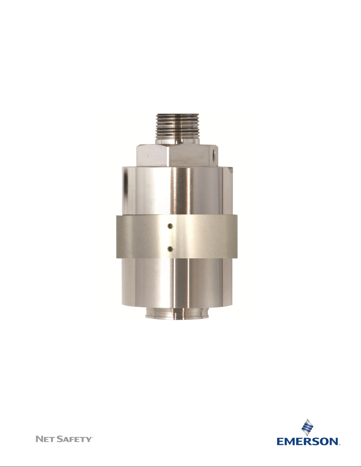
Net Safety™ SC311
Infrared Combustible Sensor
Reference Manual
00809-0100-4311, Rev AA
May 2019
Page 2

Important instructions
Net Safety™ designs, manufactures, and tests products to function within specific conditions. Because these products are
sophisticated technical instruments, the owner and operation personnel must strictly adhere to both the information printed on
the product nameplate and all instructions provided in this manual prior to installation, operation, and maintenance.
WARNING
Explosions and hazardous substances
Installing, operating, or maintaining a Net Safety product improperly could lead to serious injury or death from explosion or
exposure to dangerous substances.
Comply with all information on the product, in this manual, and in any local and national codes that apply to this product.
Use Net Safety parts and work procedures specified in this manual.
WARNING
Physical access
Unauthorized personnel may potentially cause significant damage to and/or misconfiguration of end users’ equipment. This
could be intentional or unintentional and needs to be protected against.
Physical security is an important part of any security program and fundamental to protecting your system. Restrict physical
access by unauthorized personnel to protect end users’ assets. This is true for all systems used within the facility.
Notice
The contents of this publication are presented for informational purposes only, and while every effort has been made to ensure
their accuracy, they are not to be construed as warranties or guarantees, expressed or implied, regarding the products or services
described herein or their use or applicability. All sales are governed by Net Safety™'s terms and conditions, which are available
upon request.
Net Safety does not assume responsibility for the selection, use, or maintenance of this product. Responsibility for proper
selection, use, and maintenance of any Net Safety product remains solely with the purchaser and end user.
To the best of Net Safety's knowledge, the information herein is complete and accurate. Net Safety makes no warranties,
expressed or implied, including implied warranties of merchantability and fitness for a particular purpose, with respect to this
manual, and in no event, shall Net Safety be liable for any incidental, punitive, special, or consequential damages, including, but
not limited to, loss of production, loss of profits, loss of revenue, or use and costs incurred including without limitation for capital,
fuel and power, and claims of third parties.
All rights reserved. No part of this work may be reproduced or copied in any form or by any means (graphic, electronic, or
mechanical) without first receiving written permission from Emerson.
Warranty
Three years
2
Page 3

Reference Manual
00809-0100-4311 May 2019
Introduction
1 Introduction
1.1 Models covered
The Net Safety™ SC311 infrared combustible gas sensor is designed specifically for use
with the Net Safety Millennium II transmitter (models M21, M22, or M2B). This sensor is
both versatile and reliable for fast, accurate, and continuous monitoring of gases in
extreme environments.
The sensor consists of an explosion-proof enclosure (housing) rated for hazardous
locations and a replaceable sensor module. This sensor must only be used with a Net
Safety Millennium II series transmitter. If the sensor is connected to any other model of
transmitter, it will not function and may damage the sensor or transmitter.
1.2 Service support
For technical support, contact your local Emerson representative or the Technical Support
department at +1 866 347 3427 (toll free) or [email protected].
1.3 Return of material
To expedite the repair and return of this product, proper communication between the
customer and the factory is important.
Prerequisites
Before returning a product for repair, call +1 866 347 3427 (toll free) or email
[email protected] for a Return Material Authorization (RMA) number.
On the return of the equipment, include the following information:
1. RMA number provided to you by Net Safety™.
2. Company name and contact information.
3. Purchase order, from your company, authorizing repairs or request for quote.
Procedure
1. Ship all equipment, prepaid to:
Emerson Automation Solutions
6021 Innovation Blvd
Shakopee, MN 55379
2. Mark all packages with Return for Repair and include RMA number and type of return
(e.g., return for evaluation).
Pack items to protect them from damage and use anti-static bags or aluminumbacked cardboard as protection from electrostatic damage.
Net Safety SC311 3
Page 4

Introduction Reference Manual
May 2019 00809-0100-4311
Important
All equipment must be shipped prepaid. Emerson will not accept collect shipments.
1.4 Product recycling/disposal
Consider recycling equipment and packaging. Dispose of the product and packaging in
accordance with local and national legislations and regulations.
4 Emerson.com/FlameGasDetection
Page 5

Reference Manual
00809-0100-4311 May 2019
Install
2 Install
2.1 Unpack and inspect
Carefully remove all the components from the packaging and check them against the
enclosed packing list. Inspect all components for any obvious damage such as broken or
loose parts. If you find any components missing or damaged, notify your local Net Safety
representative or the factory immediately.
2.2 Locate sensor
Prior to installation, plan where to place the sensor. Although there are no absolute rules
determining the quantity of detectors or location of a sensor, consider the following
points.
CAUTION
™
Avoid placing the sensor where it may be exposed to splashing or direct water sprays. A
splashguard may be required to protect the sensor.
• Carefully locate the sensor in an area where gases may potentially accumulate,
considering that light gases tend to rise and heavy gases tend to accumulate in low
areas.
• Use redundant systems to enhance protection and reliability.
• Consider the air movement patterns within the facility.
• Consider the construction of the facility, such as trenches where heavy gases or peaks
where light gases may accumulate.
• Seek advice from experts knowledgeable about the primary gas to be detected.
• Refer to the regulatory publications that discuss guidelines for your industry.
2.3 Direct mount or sensor separation
2.3.1 Direct mount
You can attach the sensor directly to a Net Safety™ Millennium II transmitter and place it in
an appropriate location for detecting the target gas or separate the sensor and remotely
mount it away from the transmitter.
Make sure the sensor is accessible for calibration and maintenance purposes and that the
transmitter is accessible and visible.
Net Safety SC311 5
Page 6
Install
May 2019 00809-0100-4311
Reference Manual
2.3.2 Remote mount
If mounting the sensor remotely, make sure it is connected to a certified junction box.
Locate the transmitter near eye-level for easy access and the mount the sensor where gas
is likely to accumulate.
To ease the calibration process, attach a calibration cup (CCS-1) to the bottom of the
sensor housing and run calibration tubing from the calibration cup to a convenient place
for applying calibration gas, eliminating the need to access the sensor directly. To
compensate for distance, you may decrease the calibration tubing length so that the end
of the tubing to the gas canister is still accessible or increase the calibration gas flow rate
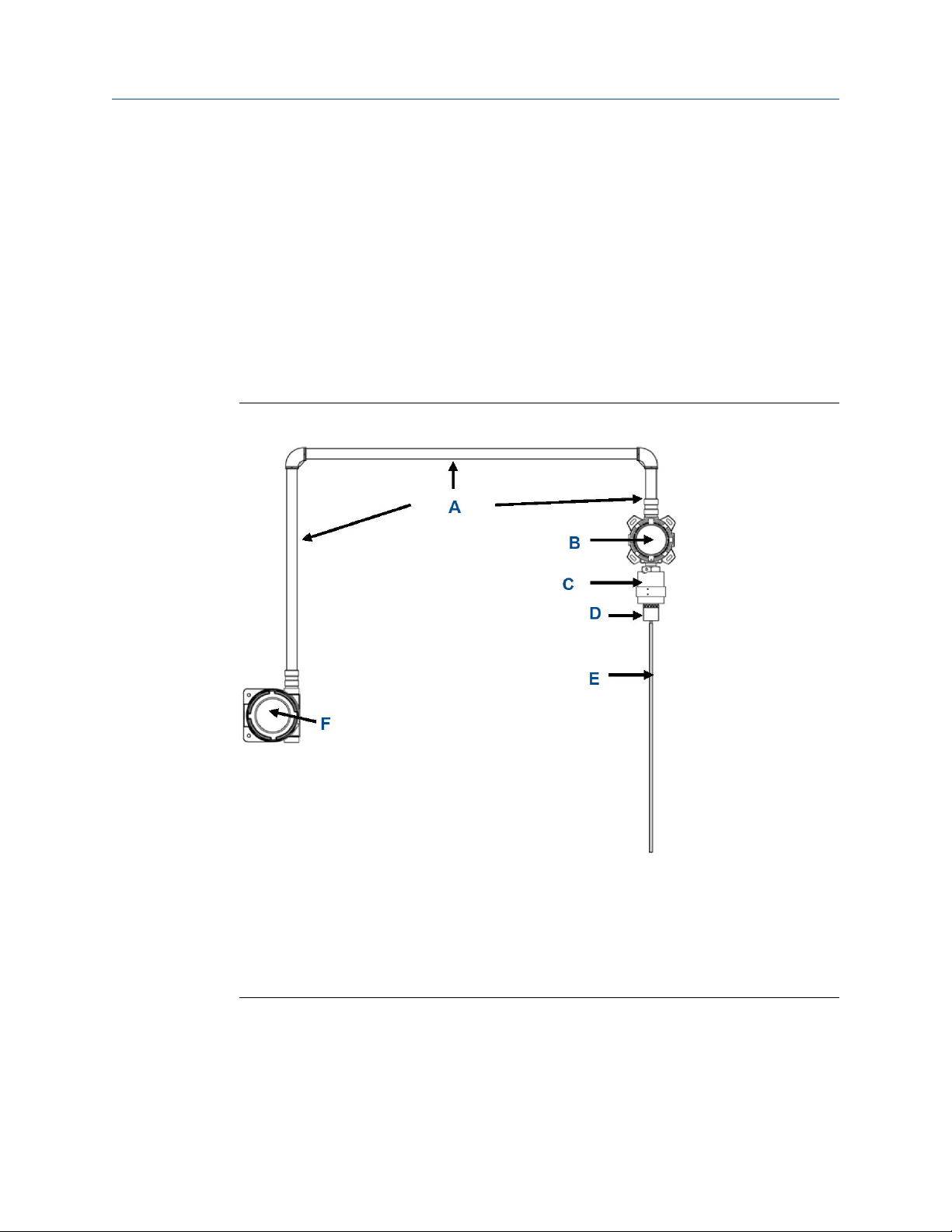
between the calibration gas cylinder and sensor. Refer to Figure 2-1 for an example of
sensor separation.
Figure 2-1: Example of Sensor Separation
A. Conduit
B. Separation junction box
C. Net Safety™ Millennium II SC311 sensor
D. CCS-1 calibration cup
E. Calibration tubing
F. Net Safety Millennium II transmitter
For tubing lengths less than 10 ft. (3 m), use an 0.5 LPM regulator; for lengths greater than
10 ft. (3 m), use a 1.0 LPM regulator. On initial install, confirm readings directly at the
transmitter by applying a known gas concentration to the sensor and comparing the
output results. Readings should be accurate to the calibration gas concentration used,
taking into account the sensor accuracy specifications in .
6 Emerson.com/FlameGasDetection
Page 7
Reference Manual Install
00809-0100-4311 May 2019
2.4 Dimensions
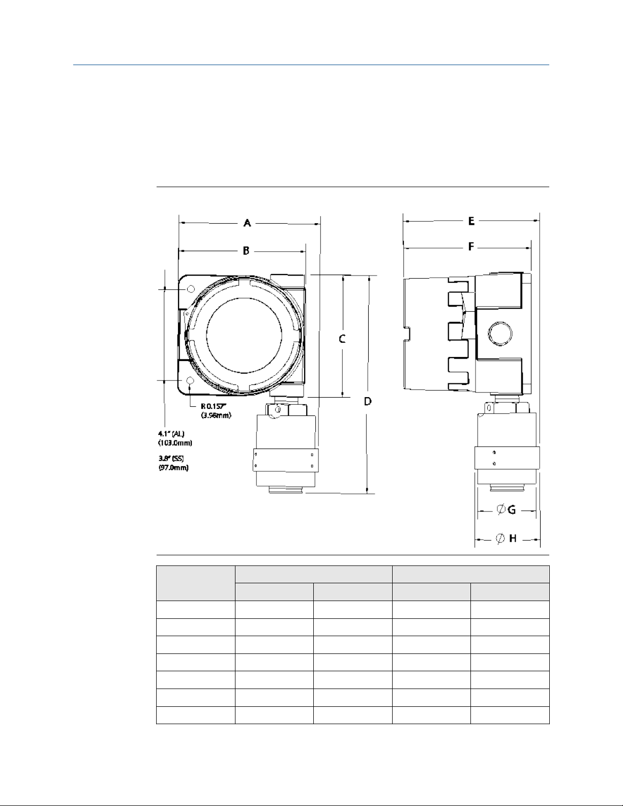
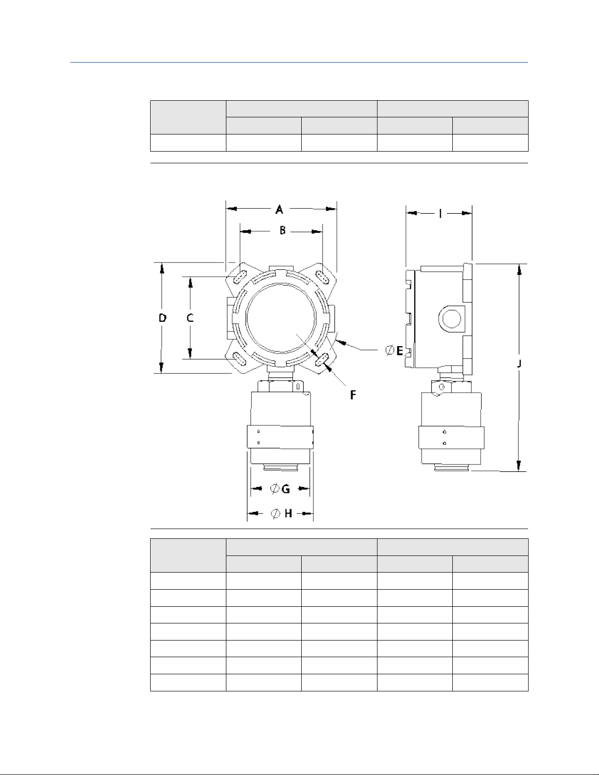
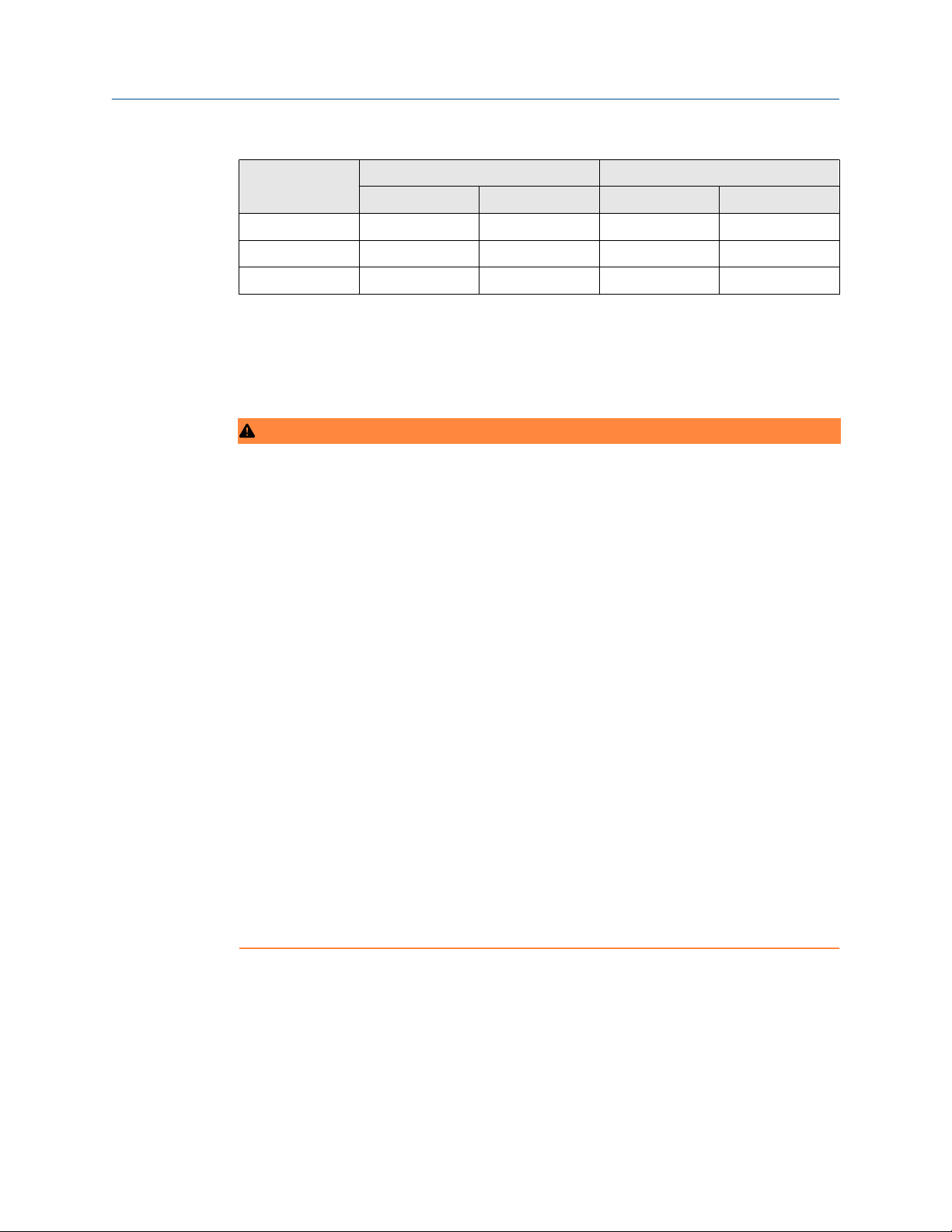
The following tables outline the dimensions of the sensor when connected to either the
Net Safety™ Millennium II transmitter or the Net Safety Millennium II basic transmitter/
junction box. Both the transmitter and sensor enclosures are offered in aluminum and
stainless steel.
Figure 2-2: Net Safety Millennium II (M21 or M22) Enclosure and Sensor Dimensions
Dimensions Stainless steel Aluminum
in. mm in. mm
A 5.9 150 6.3 160
B 5.1 130 5.6 142
C 4.6 117 5.4 137
D 8.9 226 9.7 246
E 6.0 152 6.0 152
F 5.8 147 5.7 145
G 2.6 66 2.6 66
Net Safety SC311 7
Page 8
Install Reference Manual
May 2019 00809-0100-4311
Dimensions Stainless steel Aluminum
in. mm in. mm
H 2.9 74 2.9 74
Figure 2-3: Net Safety Millennium II Basic (M2B) or Junction Box (JB) Enclosure and
Sensor Dimensions
Dimensions Stainless steel Aluminum
in. mm in. mm
A 4.7 119 4.8 122
B 3.6 91 3.6 91
C 3.6 91 3.6 91
D 4.7 199 4.8 122
E 5.1 130 5.1 130
F 0.3 7.6 0.3 7.6
G 2.6 66 2.6 66
8 Emerson.com/FlameGasDetection
Page 9
Reference Manual
00809-0100-4311 May 2019
Dimensions Stainless steel Aluminum
in. mm in. mm
H 2.9 74 2.9 74
I 2.8 71 3.0 76
J 8.9 226 9.0 229
Install
2.5 Wire
2.5.1 Field installation
WARNING
Follow guidelines
Failure to follow safety instructions could result in serious injury or death.
Ensure only qualified personnel perform the installation.
Electrical shock
Electrical shock could cause death or serious injury.
Use extreme caution when making contact with the leads and terminals.
Explosions
Do not open the transmitter, sensor, or junction box enclosure when in a classified area
or when an explosive atmosphere may be present unless the power to the transmitter
and sensor has been removed.
Wiring codes and regulations may vary.
Wiring must comply with all applicable regulations relating to the installation of
electrical equipment in a hazardous area and is the installer's responsibility.
If in doubt, consult a qualified official before wiring the system.
When separating the sensor from the transmitter, Emerson highly recommends
using shielded cable to protect against interference caused by extraneous electrical
or electromagnetic noise.
In applications where the wiring is installed in a conduit, do not use the conduit for
wiring to other equipment.
2.5.2
Net Safety SC311 9
External ground
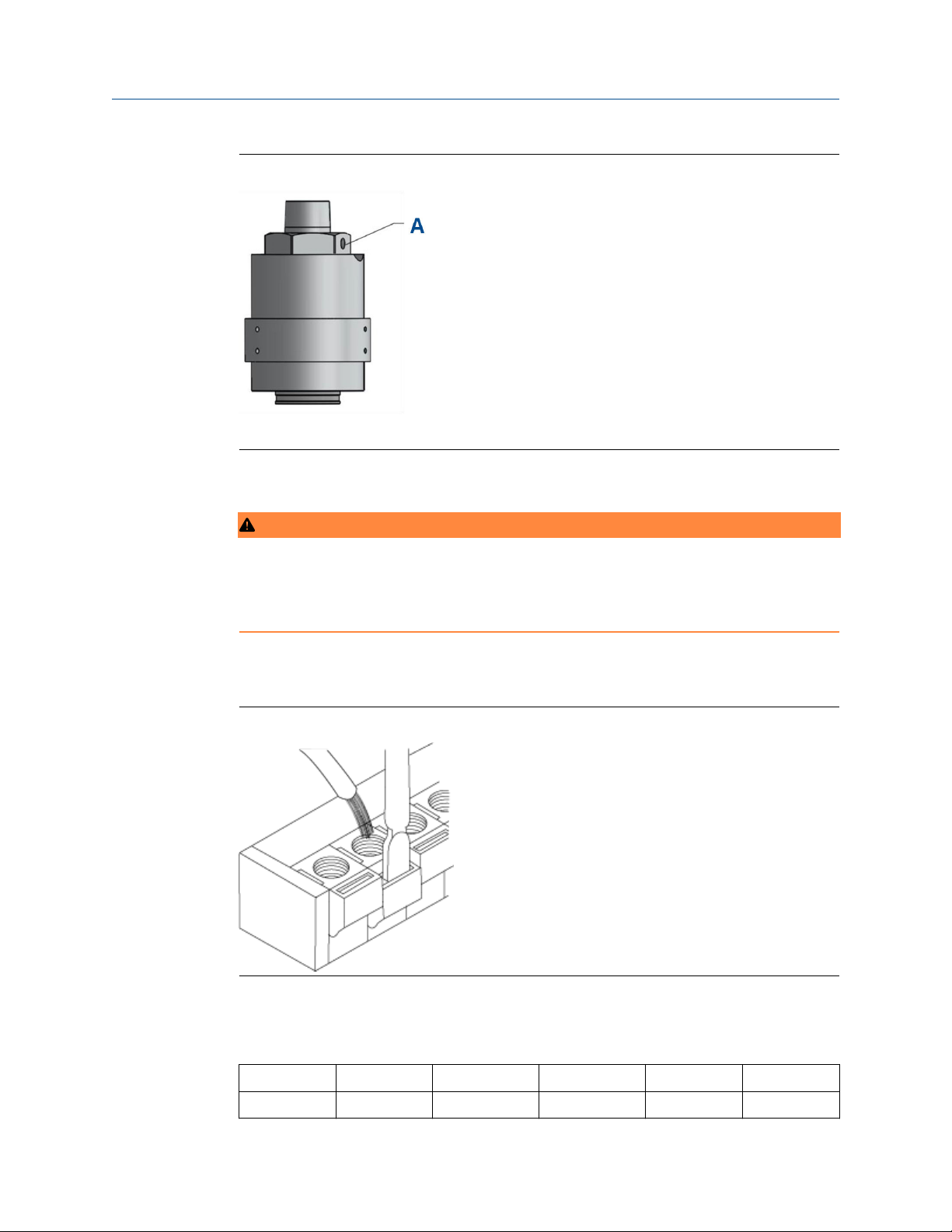
In order to ensure proper operation of the sensor, an external ground is required. The
external ground must be connected to the grounding point on the enclosure according to
IECEx requirements. Refer to Figure 2-4 for grounding connection location.
Page 10
Install Reference Manual
May 2019 00809-0100-4311
Figure 2-4: External Grounding Point
A. External earth ground point
2.5.3
Wire sensor
WARNING
Do not open the transmitter, sensor, or junction box enclosure when in a classified area
or when an explosive atmosphere may be present unless the power to the sensor has
been removed.
When connecting cable wires, use a small flathead screwdriver to gently press down and
hold the spring connector open. Insert the appropriate wire into the open connector hole,
releasing the screwdriver to secure the wire. Refer to Figure 2-5.
Figure 2-5: Terminal Connection
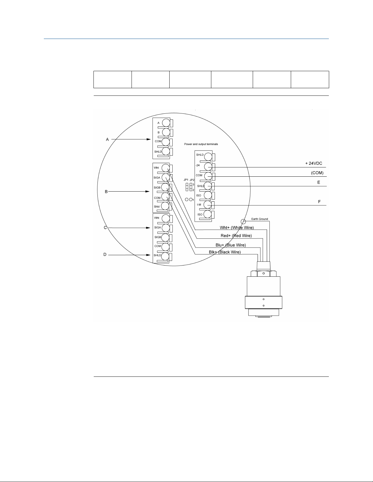
Connect sensor wires to the sensor terminals in the applicable transmitter. Refer to the
Table 2-1 for the wire colors and their purposes..
Table 2-1: Sensor wires and Millennium II series Terminal definitions
Sensor wire White Red Blue Black Green
Marked +Vdc Sig A Sig B COM
10 Emerson.com/FlameGasDetection
Page 11
Reference Manual
00809-0100-4311 May 2019
Table 2-1: Sensor wires and Millennium II series Terminal definitions (continued)
Install
Function
Figure 2-6: Net Safety Millennium II M21 Sensor Wiring
10.5 - 32 Vdc
connection
Communication signal A
Communication signal B
Common/
supply ground
Earth ground
A. Modbus® terminals
B. Channel 1 sensor terminals
C. Channel 2 sensor terminals
D. Net Safety™ Millennium II transmitter terminal board
E. Channel #1 4-20 mA signal
F. Channel #2 4-20 mA signal
2.5.4
Net Safety SC311 11
Installation checklist
Review the following checklist prior to turning on power to the sensor after completing
installation.
• Ensure transmitter and sensor are properly and firmly mounted.
• Ensure that stopping plug is tightened on any unused conduit entries.
Page 12

Install Reference Manual
May 2019 00809-0100-4311
• Ensure transmitter and sensor are not being obstructed, transmitter and sensor are
accessible, and target gas is not inhibited from reaching sensor.
• Remove the red protective plastic cap/cover from sensor mouth.
• If calibration cups or splash guards are fitted to sensor, ensure a snug fit.
• Ensure adherence to applicable local guidelines and requirements on wiring and
sealing of equipment in hazardous and non-hazardous areas.
• Ensure that proper shielding and grounding practices are adhered to and local codes
are being followed.
• Check system operational voltage and conditions and ensure that they are within the
applicable specifications of the sensor.
• Verify wiring at all termination and junction points (transmitter, junction box, and
power supply).
• If the sensor housing has been opened, ensure that the sensor module is properly
seated and making a good connection. Refer to Replace sensor for more details.
• Perform initial calibration as per Calibrate.
12 Emerson.com/FlameGasDetection
Page 13

Reference Manual Operate
00809-0100-4311 May 2019
3 Operate
3.1 Configuration settings
You can access all configuration settings for the Net Safety™ SC311 through the Net Safety
Millennium II series of transmitters.When using the Net Safety Millennium II transmitter,
access configuration settings by selecting menu options through the main display.
Tip
Refer to the relevant transmitter manual prior to calibrating.
3.2 Power up
When power is applied to the sensor by the transmitter, a warm-up routine will begin, and
the sensor will be automatically tested to ensure proper functioning. The warm-up time
for the Net Safety™ SC311 is typically 90 seconds. Refer to the Net Safety Millennium II
Transmitter Reference Manual or the Net Safety Millennium II Basic Transmitter Reference
Manual for status indicators during this period.
3.3 Communication
The Net Safety™ SC311 sensor uses a proprietary protocol to communicate with the Net
Safety Millennium II series transmitters.
Never connect these sensors to a device other than Net Safety Millennium II series
transmitters. Selected DIP switches and menu options allow communication between
transmitters and sensors. The sensor's memory stores configuration settings. Incorrect
settings will cause sensors not to communicate properly with transmitters. If any
problems develop, see Troubleshoot.
3.4 Net Safety™ Millennium II basic transmitter configuration
When using the Net Safety SC311 with the Net Safety Millennium II basic transmitter, set
the transmitter DIP switch as follows.
Table 3-1: Net Safety Millennium II Basic Transmitter DIP Switch 2 Positions
Gas curve Position 1 Position 2 Position 3 Position 4
Methane (0) Off Off Off Off
Propane (1)
n-Butane (2)
Iso-Pentane (3)
n-Pentane (4)
(1)
On Off Off Off
(1)
Off On off Off
(1)
On On Off Off
(1)
Off Off On Off
Net Safety SC311 13
Page 14

Operate Reference Manual
May 2019 00809-0100-4311
Table 3-1: Net Safety Millennium II Basic Transmitter DIP Switch 2 Positions
(continued)
Gas curve Position 1 Position 2 Position 3 Position 4
Ethane (5) On Off On Off
(1)
(1)
Off On On Off
Off Off Off On
Iso-Butane (6)
Ethylene (7) On On On Off
Hexane (8)
Propylene (9) On Off Off On
(1) Gas is not third party performance verified.
3.5 Fault conditions
The sensor provides a number of fault conditions that the transmitter translates into an
analog or fault relay output. These fault conditions are outlined in the following table:
Table 3-2: Fault Conditions
Fault condition Analog output (mA) Fault relay output
Span calibration failure 2.5 Fault
Zero calibration failure 2.5 Fault
Sensor over-range 2.5 Fault
Low temperature 2.5 Fault
High temperature 2.5 Fault
Low voltage 2.5 Fault
High voltage 2.5 Fault
Replace sensor (during calibration cycle) Momentary 2.5 Momentary fault
Memory fault 2.5 Fault
Power supply fault 2.5 Fault
14 Emerson.com/FlameGasDetection
Page 15

Reference Manual Output
00809-0100-4311 May 2019
4 Output
4.1 Alarm and fault outputs
Sensor alarm and fault outputs are generated by the Net Safety™ Millennium II series
transmitters based on communication with sensors; however, some output values,
registers, etc. may vary depending on sensor type. The default alarm levels (points) for the
sensor are: 20 percent for the low level and 40 percent for the high level.
4.1.1 Other available outputs
All available outputs are associated with the Net Safety™ Millennium II series transmitters.
These outputs are: 4-20 mA output, relay output, RS 485 Modbus® (RTU) output and
HART® communication output. Refer to the Net Safety Millennium II Basic Transmitter
Reference Manual or the Net Safety Millennium II Multichannel Transmitter Reference
Manual for more information.
4.1.2
Modbus registers
Table 4-1 below shows the user accessible Modbus registers and meaning.
Table 4-1: Modbus Registers
Register # Meaning Readable Writeable
40001
40002 Sensor status X
40003 Sensor temperature X
40009 Select target gas X X
40101 Resets the sensor X
40102 Initialize zero & span
40104 Zero only
(1) To calibrate sensor, enter channel number.
(2) To zero sensor, enter channel number.
Note
For the Net Safety™ Millennium II Basic Transmitter enter 1 in register 40102 to calibrate
the sensor and 1 in register 40104 to zero the sensor.
Concentration value as calculated by
sensor
(1)
(2)
X
X
X
Net Safety SC311 15
Page 16

Output Reference Manual
May 2019 00809-0100-4311
16 Emerson.com/FlameGasDetection
Page 17

Reference Manual Maintenance
00809-0100-4311 May 2019
5 Maintenance
5.1 Calibrate
Note
According to instrumentation best practices, the Net Safety™ SC311 should be powered
up for at least 30-60 minutes prior to completing the first calibration.
You must calibrate the infrared sensor with the target gas for the application and the gas
the sensor is programmed for. The calibration gas can be either air or nitrogen based.
Calibrate the sensor every twelve months. In environments where the sensor may be
routinely exposed to gas concentrations or airborne contaminants, verify or calibrate the
sensor more frequently. The calibration gas must be between 5 and 113 °F (-15 and 45 °C)
to meet accuracy specifications.
Since external factors can affect the sensor's ability to properly detect gas, Emerson highly
recommends quarterly inspections and bump tests to ensure proper operation of the gas
detection system.
If using accessories with the sensor, calibrate with these accessories in place.
5.1.1
There are specific steps to be followed when calibrating with the Net Safety Millennium II
transmitters. Refer to the appropriate transmitter manual for calibration procedures.
Follow these steps to obtain accurate results.
Calibrate with the Net Safety™ Millennium II Basic Transmitter
When using the IR sensor with the Net Safety Millennium II Basic Digital Transmitter
Model, access a specific Modbus® register to select or change the target gas. Write to
register 40009 using the preset single register command 0x06 to change the target gas.
To select the target gas, enter the gas curve number that corresponds to the target gas
from Table 5-1 below.
The table below outlines the primary detected gases of this sensor, however, multiple
other gases are detectable. Please contact your representative regarding any gases not
included in this table.
Table 5-1: Target Gas with Gas Curve Numbers
Target gas Gas curve numbers
Methane 0
Propane 1
*n-Butane 2
*Iso-Pentane 3
*n-Pentane 4
Ethane 5
Net Safety SC311 17
Page 18

Maintenance
May 2019 00809-0100-4311
Reference Manual
Table 5-1: Target Gas with Gas Curve Numbers (continued)
Target gas Gas curve numbers
*Iso-Butane 6
Ethylene 7
*Hexane 8
* Indicates gases not performance certified.
When using the IR sensor with the Net Safety Millennium II Basic analog, analog HART
®
and relay transmitter models, make use of the transmitter’s DIP Switch 2 positions, as seen
in Table 5-2 below, to select the target gas, and then follow the normal calibration
procedure to perform calibrations. Use 50% LEL of the specific gas to be detected for
calibration. See Table 5-2 and Full Calibration / Normal Calibration Procedure below.
If calibration is not successful perform a manual reset. See Net Safety Millennium II Basic
Reference Manual for manual reset.
Example: If the target gas is propane, set Dip Switch 2 position 1 in the ON position and
positions, 2, 3 and 4 in the OFF position. This corresponds to propane (Curve 2); then use
50% LEL propane for calibration.
Table 5-2: Net Safety Millennium II Basic Transmitter DIP Switch 2 Positions/Combinations
Position 1 Position 2 Position 3 Position 4 Gas curves
OFF OFF OFF OFF Curve 1 (methane)
ON OFF OFF OFF Curve 2 (propane)
OFF ON OFF OFF * Curve 3 (n-butane)
ON ON OFF OFF
OFF OFF ON OFF * Curve 5 (n-pentane)
ON OFF ON OFF Curve 6 (ethane)
OFF ON ON OFF *Curve 7 (iso-butane)
ON ON ON OFF Curve 8 (ethylene)
OFF OFF OFF ON *Curve 9 (hexane)
ON OFF OFF ON Curve 10 (TBA)
OFF ON OFF ON Curve 11 (TBA)
ON ON OFF ON Curve 12 (TBA)
OFF OFF ON ON Curve 13 (TBA)
ON OFF ON ON Curve 14 (TBA)
OFF ON ON ON Curve 15 (TBA)
*Curve 4 (isopentane)
ON ON ON ON Curve 16 (TBA)
* Indicates gases not performance certified
18 Emerson.com/FlameGasDetection
Page 19

Reference Manual
00809-0100-4311 May 2019
Maintenance
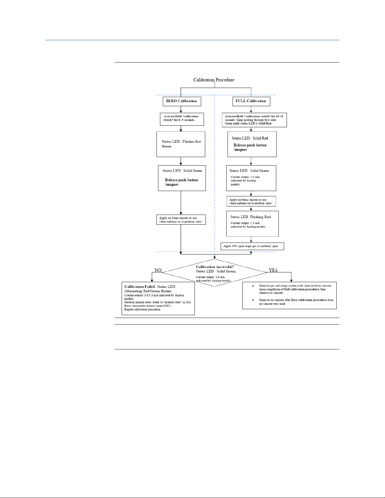
If the sensor’s configuration setting (curve) is setup correctly as desired, refer to
Millennium II Basic Transmitter calibration procedure below and/or Figure 5-1 before
attempting calibration.
You can calibrate with either the magnet (non-intrusive) or the push button (intrusive).
Procedure
1. Confirm successful power up of transmitter, (green blip/blink of status LED every
second: no fault indicated).
2. Bypass any output alarms (recommended).
3. For analog model connect a standard current meter to the transmitter’s test jacks.
This is not required but gives visual confirmation.
4. Press and hold the push button (or activate the reed switch using the magnet) for at
least 15 seconds, the status LED flashes green fast and then goes solid green (first
solid green).
5. Keep holding push button or magnet, after which status LED goes solid red. When
this occurs, release push button or remove magnet.
6. When the current output is 3 mA (indicated by analog models) and the status LED is
once again solid green (second solid green), apply zero gas (clean air).
Recommendation: Flow zero air at a rate of 0.5 liter per minute or more to the
sensor.
7. When the current output is 3.3 mA (indicated by analog models) and the status LED
is flashing red, apply specific calibration gas (50 percent of full span).
Recommendation: Flow span gas at a rate of 0.5 liter per minute to the sensor for
direct sensor calibrations. If sensor is remotely mounted and long tubing run is
used, increase gas flow rate (e.g. 1.0 liter per minute) to ensure tubing length does
not affect calibration results.
8. When the current output is 3.6 mA (indicated by analog models) and the status LED
is solid green, remove the gas.
9. Apply zero gas (clean air) again to purge the system.
After the sensor is purged of gas, the detector will return to normal operation.
Note
When calibrating with the Net Safety Millennium II Basic Transmitter always use 50
percent span gas (half the scale). Calibration gas can be air balanced or nitrogen
balanced for IR sensors. You can also access calibration instructions from the HART
Communicator with the analog/HART model transmitter. For HART menu structure,
see Net Safety Millennium II Basic Transmitter Reference Manual.
Zero calibration option: This option is useful if the sensor’s zero point has drifted as
a result of a change in the ambient conditions. Only select the zero calibration
option if a sensor is only being zeroed (this not a complete calibration). It does not
require the application of span gas, as only the sensor’s zero point is adjusted.
Ensure that no contaminants are present if the surrounding air is to be used for
zeroing. If Zero calibration is needed, at Step 4, hold the push button or activate
reed switch (for 6-9 seconds) using the magnet until the status LED goes solid
green, and then release the switch. Zero calibration will begin immediately. See
Figure 5-1 for additional reference.
Net Safety SC311 19
Page 20
Maintenance
May 2019 00809-0100-4311
Figure 5-1: Calibration Flow chart for Millennium II Basic Transmitter
Reference Manual
Note
See the Net Safety Millennium II Basic Transmitter Reference Manual when locating
calibration switch (push button) or magnetic switch.
5.1.2
Calibrate with the Net Safety™ Millennium II MultiChannel Transmitter
The Net Safety Millennium II Transmitter allows monitoring and detection of various
combustible gases. The following procedures are specific to this transmitter; follow them
to ensure accurate calibration and detection of gases.
To select the target gas:
20 Emerson.com/FlameGasDetection
Page 21

Reference Manual
00809-0100-4311 May 2019
Maintenance
Procedure
1. Enter the Main menu, first by pressing any key to get the enter main menu
prompt, then press menu button 1 (reed switch 1) to select yes.
2. Select the up arrow key (menu button 1 or reed switch 1) or down arrow key
(menu button 2 or reed switch 2), until Select Gas Type is displayed.
3. Select the Enter key (menu button 3 or reed switch 3) to enter the option.
4. If configuring channel 1's gas type, select it with the Enter key (menu button 3 or
reed switch 3.
5. If configuring channel 2's gas type, use the down arrow key (menu button 2 or reed
switch 2) and then select it with the Enter key (menu button 3 or reed switch 3).
6. If the gas type displayed is not the required target gas, select the down arrow key
(menu button 2 or reed switch 2 until the desired target gas is found.
7. Activate the enter key (menu button 3 or reed switch 3) to select the specific gas
to be detected.
8. Use the down arrow key (menu button 2 or reed switch 2) and then the Enter key
(menu button 3or reed switch 3) until the main menu is completely exited.
Refer to the Net Safety Millennium II Transmitter calibration procedure below
and/or Figure 5-2 before attempting calibration. If the sensor’s target gas is setup
correctly as desired, follow the steps below for full calibration/normal calibration
procedure.
Important
Always use 50 percent span gas (half the scale) of the specific target gas when
calibrating this sensor.
Note that if a calibration is not successful the transmitter will display the message
Span failed, and you will have to initiate a manual reset. Refer to the Net Safety
Millennium II Multi-Channel Transmitter Reference Manual for manual reset.
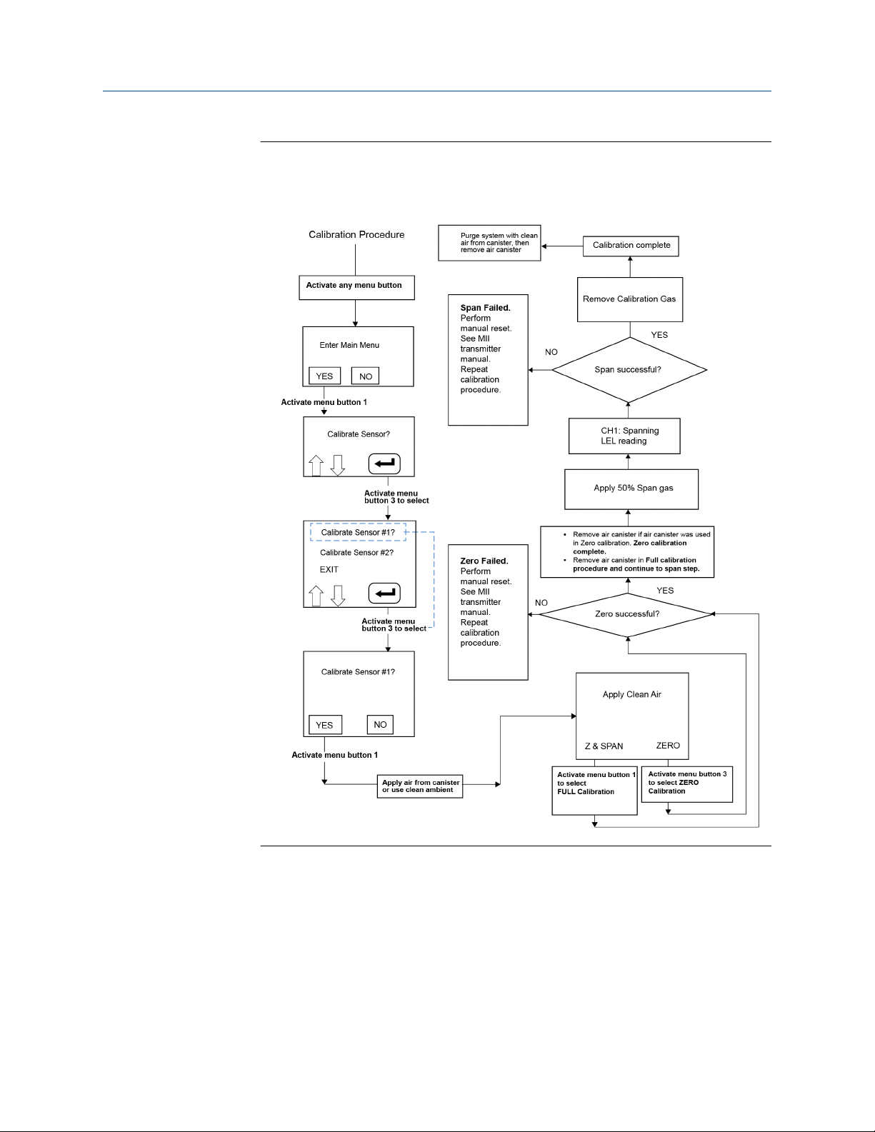
9. Enter the main menu, first by pressing any key to get the enter main menu
prompt, and then pressing or selecting menu button 1 or reed switch 1 to select
yes.
10. When Calibrate Sensor? is displayed, select the Enter key (menu button 3or
reed switch 3).
11. When Calibrate Sensor #1? is highlighted, press the Enter key (menu button
3or reed switch 3) if calibrating this sensor.
12. If calibrating sensor 2, select the down arrow key (menu button 2or reed switch 2)
to scroll to Calibrate Sensor #2?
13. When the desired sensor to be calibrated (1 or 2) is highlighted, activate the enter
key (menu button 3or reed switch 3).
14. Select YES (menu button 1or reed switch 1) to confirm the selection.
15. Apply clean air when Apply Clean Air is displayed; then select Z & Span using
( (menu button 1or reed switch 1) for normal calibration.
The transmitter will display Setting zero as the sensor is being zeroed. (Ensure
no contaminant gases are around if using ambient air).
Net Safety SC311 21
Page 22

Maintenance Reference Manual
May 2019 00809-0100-4311
16. Apply 50 percent calibration gas when prompted.
Recommendation: Flow span gas at a rate of 0.5 liter per minute to the sensor for
direct calibrations. If sensor is remotely mounted and long tubing run is used,
increase gas flow rate (e.g. 1.0 liter per minute) to ensure tubing length does not
affect calibration results.
17. The display will show Spanning with the gas value (% LEL) as the gas is detected.
18. Remove the calibration gas when Remove Cal Gas is displayed.
19. The transmitter displays Cal Complete when calibration is complete.
20. Apply zero gas (clean air) to purge system.
Note
Calibration gas can be air or nitrogen balanced. You can also access calibration
instructions from the HART® Communicator with the single channel Net Safety
Millennium II Transmitter model.
Zero calibration option: This option is useful if the sensor’s zero point has drifted as
a result of a change in the ambient conditions. Only select the Zero calibration
option if the sensor is only being zeroed (this not a complete calibration). The
application of span gas is not required, as only the sensor’s zero point is adjusted.
Ensure that no contaminants are present if using the surrounding air for zeroing. If
you need zero calibration, at Step 7 above, select Zero using menu button 3or
reed switch 3.See Figure 5-2 for additional reference. The chart shows calibration
steps for channel 1. Calibration steps for channel 2 are similar.
22 Emerson.com/FlameGasDetection
Page 23
Reference Manual
00809-0100-4311 May 2019
Figure 5-2: Calibration Flow chart for Net Safety Millennium II Multi-Channel
Transmitter
Maintenance
5.1.3 Cross sensitivities
Infrared sensors react to most compounds containing a carbon-hydrogen bond
(hydrocarbons) in varying degress, potentially providing a response from the sensors.
You need to consider other gases present within this particular application for their impact
on this sensor. For more information, please contact the manufacturer.
Net Safety SC311 23
Page 24

Maintenance
May 2019 00809-0100-4311
Reference Manual
5.2 Replace sensor
Emerson pre-calibrates sensors at the factory; however you must field calibrate as part of
commissioning. When you cannot calibrate or the sensor is not operating properly, you
may need to replace the sensor module.
WARNING
Do not open the transmitter, sensor, or junction box enclosure when in a classified area
or when an explosive atmosphere may be present unless the power to the sensor has
been removed.
CAUTION
Avoid touching any electronic components, as they may be susceptible to electrostatic
discharge (ESD). Refer to Electrostatic sensitive device (ESD) for further information
and proper handling instructions of electronic components.
Procedure
1. Remove power from the sensor.
2. Remove the locking ring by loosening the set crews with 1.5 mm Allen Key tool.
3. Remove the bottom part of the sensor enclosure by turning in a counter clockwise
direction to expose sensor module.
4. Carefully remove the sensor module from the sensor housing by pulling on the gold
sensor until the sensor cell and sensor board have been fully removed from the
housing.
In some cases, the sensor cell may disconnect from the board. This is normal, and
you can easily fit the sensor cell back onto the sensor board.
5. Disconnect the wire assembly from the sensor board to remove the sensor from the
housing.
6. Properly dispose of the old sensor module as per local guidelines and regulations.
7. Remove the replacement sensor module from its packaging, being careful not to
touch any electronic components, as this may cause problems due to unwanted
electrostatic discharge (ESD).
8. Connect the wire assembly from the sensor housing to the sensor board, being
careful not to touch any electronic components on the board.
9. Align the replacement sensor module banana plugs with the standoffs in the
housing and press the replacement sensor into place.
10. Install and hand-tighten the bottom part of the sensor enclosure by turning in a
clockwise direction.
11. Install the locking ring by tightening the set screws with 1.5 mm Allen key tool.
12. Restore power to sensor via transmitter.
24 Emerson.com/FlameGasDetection
Page 25

Reference Manual Maintenance
00809-0100-4311 May 2019
5.3 Troubleshoot
Emerson did not design sensors or transmitters to be repaired in the field. If problems
should develop, first check for faulty wiring, confirm proper voltage to sensor, and
attempt a calibration.
If problems persist, please contact the Flame and Gas Detection Customer Care team first
by phone to try and resolve any issues. If issues cannot be resolved, please follow the
procedure in Return of material.
5.4 Storage
Store the sensor and its electronic components/parts in locations free from dust, liquid
spills, contaminants, and moisture.
Make sure the storage temperature is well within the limits of the certified temperatures
of the equipment. See Specifications for certified temperatures.
5.5 Spare parts and accessories
Table 5-3: Available Spare Parts
Description Net Safety™ Part Number
Calibration cup/splash guard CCS-1
Calibration kit CAL-KIT-1
Calibration gas CAL-CYL-AIR (103 L air)
CAL-CYL-BUT (103 L butane)
CAL-CYL-ETH-A-50 (103 L ethylene)
CAL-CYL-HYD (103 L hydrogen)
CAL-CYL-METH (103 L methane)
CAL-CYL-PENT (103 L pentane)
CAL-CYL-PRO (103 L propane)
Ingress protection filter IPF-001
Separation kit JB-MPD-A: aluminum
JB-MPD-S: 316 stainless steel
Replacement sensor module SC311-100
Note
The Net Safety SC311 is not certified for performance when the calibration cup, ingress
protection filter, or dust guard is attached.
Net Safety SC311 25
Page 26

Maintenance Reference Manual
May 2019 00809-0100-4311
5.6 Return of material
To expedite the repair and return of this product, proper communication between the
customer and the factory is important.
Prerequisites
Before returning a product for repair, call +1 866 347 3427 (toll free) or email
[email protected] for a Return Material Authorization (RMA) number.
On the return of the equipment, include the following information:
1. RMA number provided to you by Net Safety™.
2. Company name and contact information.
3. Purchase order, from your company, authorizing repairs or request for quote.
Procedure
1. Ship all equipment, prepaid to:
Emerson Automation Solutions
6021 Innovation Blvd
Shakopee, MN 55379
2. Mark all packages with Return for Repair and include RMA number and type of return
(e.g., return for evaluation).
Pack items to protect them from damage and use anti-static bags or aluminumbacked cardboard as protection from electrostatic damage.
Important
All equipment must be shipped prepaid. Emerson will not accept collect shipments.
26 Emerson.com/FlameGasDetection
Page 27

Reference Manual Electrostatic sensitive device (ESD)
00809-0100-4311 May 2019
A Electrostatic sensitive device (ESD)
Definition
The most common cause of ESD is physical contact. Touching an object can cause a
discharge of electrostatic energy (ESD). If the charge is sufficient and occurs near
electronic components, it can damage or destroy those components. In some cases,
damage is instantaneous, and an immediate malfunction occurs. However, symptoms are
not always immediate; performance may be marginal or seemingly normal for an
indefinite period of time, followed by a sudden failure.
To eliminate potential ESD damage, review the following guidelines:
• Handle boards by metal shields, taking care not to touch electronic components.
• Wear grounded wrist or foot straps, ESD shoes, or heel grounders to dissipate
unwanted static energy.
• Prior to handling boards, dispel any charge in your body or equipment.
• Ensure all components are transported and stored in static safe packaging.
• When returning boards, carefully package in the original carton and static protective
wrapping.
• Ensure all personnel are educated and trained in ESD control procedures.
In general, exercise accepted and proven precautions normally observed when handling
electrostatic sensitive devices. A warning label is placed on the packaging, identifying
product using electrostatic sensitive semiconductor devices.
Electrostatic discharge (ESD) is the transfer, between bodies, of an
electrostatic charge caused by direct contact or induced by an electrostatic
field.
Net Safety SC311 27
Page 28

Electrostatic sensitive device (ESD) Reference Manual
May 2019 00809-0100-4311
28 Emerson.com/FlameGasDetection
Page 29

Reference Manual Wire resistance table
00809-0100-4311 May 2019
B Wire resistance table
Distance: feet
(meters)
100 (30.5) 1.02 0.64 0.40 0.25
200 (61) 2.03 1.28 0.80 0.51
300 (91.4) 3.05 1.92 1.20 0.76
400 (121.9) 4.06 2.55 1.61 1.01
500 (152.4) 5.08 3.20 2.01 1.26
600 (182.9) 6.09 3.83 2.41 1.52
700 (213.4) 7.11 4.47 2.81 1.77
800 (243.8) 8.12 5.11 3.21 2.02
900 (274.3) 9.14 5.75 3.61 2.27
1000 (304.8) 10.20 6.39 4.02 2.53
1250 (381) 12.70 7.99 5.03 3.16
1500 (457.2) 15.20 9.58 6.02 3.79
1750 (533.4) 17.80 11.20 7.03 4.42
2000 (609.6) 20.30 12.80 8.03 5.05
2250 (685.8) 22.80 14.40 9.03 5.68
2500 (762) 25.40 16.00 10.00 6.31
AWG #20
0.5 mm2 (ohms)
AWG #18
0.8 mm2 (ohms)
AWG #16
1.0 mm2 (ohms)
AWG #14
2.0 mm2 (ohms)
3000 (914.4) 30.50 19.20 12.00 7.58
3500 (1066.8) 35.50 22.40 14.10 8.84
4000 (1219.2) 40.60 25.50 16.10 10.00
4500 (1371.6) 45.70 28.70 18.10 11.40
5000 (1524) 50.10 32.00 20.10 12.60
5500 (1676.4) 55.80 35.10 22.10 13.91
6000 (1828.8) 61.00 38.30 24.10 15.20
6500 (1981.2) 66.00 41.50 26.10 16.40
7000 (2133.6) 71.10 44.70 28.10 17.70
7500 (2133.6) 76.10 47.90 30.10 19.00
8000 (2438.4) 81.20 51.10 23.10 20.20
9000 (2743.2) 91.40 57.50 36.10 22.70
10000 (3048) 102.00 63.90 40.20 25.30
Resistance shown is one way. This figure should be doubled when determining closed loop
resistance.
Net Safety SC311 29
Page 30

Wire resistance table Reference Manual
May 2019 00809-0100-4311
30 Emerson.com/FlameGasDetection
Page 31

Reference Manual Specifications
00809-0100-4311 May 2019
C Specifications
Voltage range 10.5 to 32 Vdc
Performance
T50 < 4.3 sec
Response time
Accuracy ± 5% LEL or 10% of applied, whichever is greater
Zero drift < 5% full scale per year
Repeatability ±2% LEL Full Scale
Detection range 0-100% LEL
Calibration frequency 12 months
Environmental
T60 < 7.0 sec
T90 < 11.0 sec
(1)
(1)
Storage temperature -40 °F to +158 °F (-40 °C to +70 °C)
Operating temperature -40 °F to +167 °F (-40 °C to +75 °C)
Relative humidity 0 – 99% relative humidity, non-dondensing
Enclosure material (housing) 316 stainless steel and 6061 aluminum
Ingress protection IP64
Weight
Separation Up to 2000 ft. (610 m) with 18 AWG (1.02 mm2) wire
Warranty 5 years
(1) Methane at room temperature
Stainless steel: 3.5 lb. (1.4 kg)
Aluminum: 1 lb. (0.4 kg)
Net Safety SC311 31
Page 32

Specifications Reference Manual
May 2019 00809-0100-4311
32 Emerson.com/FlameGasDetection
Page 33

Reference Manual Product certifications
00809-0100-4311 May 2019
D Product certifications
D.1 North America
D.1.1 Hazardous locations
Class I, Division 1, Groups BCD T5
Class I, Zone 1, AEx/Ex d IIB +H2 T5
-40 °C ≤ Ta ≤ +75 °C
D.1.2
Performance
CSA C22.2 No. 152: 2006
FM Class 6310, 6320: 2001
ANSI/ISA 12.13.01:2000
D.2 IECEx
Ex d IIB+H2 T5 Gb
IECEx FMG 12.0007X
Special conditions for safe use:
1. Consult the manufacturer if dimensional inforation on the flameproof joints is
necessary.
2. The flying leads of the Net Safety™ Millennium II sensor shall be suitably protected
against mechanical damage and terminated within a terminal or junction facility
suitable for the conditions of use.
D.3 FC models
Net Safety™ SC311 infrared sensors, models SC311x-100-ASSY-FC, when used with
wireless capable Net Safety Millennium II transmitters, carry the following certifications.
All certifications outlined above do not pertain to these models.
D.3.1
Net Safety SC311 33
North America (-FC models)
Class I, Division 1, Groups BCD T5
Class I, Zone 1, AEx/Ex d IIB+ H2 T5
Page 34

Product certifications Reference Manual
May 2019 00809-0100-4311
-40 °C ≤ Ta ≤ +75 °C
CSA C22.2 No. 152 FM6320
D.3.2 IECEx (-FC models)
Ex d IIB+H2 T5 Gb
-40 °C ≤ Ta ≤ +75 °C
IECEx FMG 12.0007X
Special conditions for safe use
1. Consult the manufacturer if dimensional information on the flameproof joints is
necessary.
2. The flying leads of the Net Safety™ Millennium II sensor shall be suitably protected
against mechanical damage and terminated within a terminal or junction facility
suitable for the conditions of use.
34 Emerson.com/FlameGasDetection
Page 35
Reference Manual Ordering information
00809-0100-4311 May 2019
E Ordering information
Model
SC311 Net Safety™ Millennium II infrared combustible gas sensor
Housing
A Aluminum
S Stainless steel
Range
100-ASSY 100% LEL
Wireless
FC When used with wireless capable Net Safety Millennium II
transmitters
Net Safety SC311 35
Page 36

00809-0100-4311
Rev. AA
2019
GLOBAL HEADQUARTERS
6021 Innovation Blvd.
Shakopee, MN 55379
+1 866 347 3427
+1 952 949 7001
[email protected]
EUROPE
Emerson Automation Solutions
Neuhofstrasse 19a PO Box 1046
CH-6340 Baar
Switzerland
+41 (0) 41 768 6111
+41 (0) 41 768 6300
[email protected]
Linkedin.com/company/Emerson-Automation-Solutions
twitter.com/rosemount_news
Facebook.com/Rosemount
youtube.com/RosemountMeasurement
MIDDLE EAST AND AFRICA
Emerson Automation Solutions
Emerson FZE
Jebel Ali Free Zone
Dubai, United Arab Emirates, P.O. Box 17033
+971 4 811 8100
+971 4 886 5465
[email protected]
©
2019 Emerson. All rights reserved.
The Emerson logo is a trademark and service mark of Emerson Electric Co. Net Safety is a
mark of one of the Emerson family of companies. All other marks are the property of their
respective owners.
ASIA-PACIFIC
Emerson Automation Solutions
1 Pandan Crescent
Singapore 128461
Republic of Singapore
+65 6 777 8211
+65 6 777 0947
[email protected]
 Loading...