

Page 1

Surge an
d Signal Protection
for Business-Critical Continuity
Liebert Hybrid Advantage
Total Protection For Your High Availability Systems
Page 2
Multi-Stage System of Suppression
S•A•D Hybrid Technology
The Liebert Hybrid Advantage is the first hybrid product in the industry to offer a
true, coordinated multi-stage system of suppression. It integrates the fast response
time of the Silicone Avalanche Diode (SAD) with the high-energy capability of
the standard Liebert Interceptor MOV (Metal Oxide Varistor). Its patent-pending
Surge Current Transition Circuit continually monitors the operating level of the
SAD-switching to the secondary network of MOVs long before component failure
becomes a concern.
Other "hybrid" products fall into one of
two categories:
Self-sacrificing: This system significantly degrades or
fails with nominal fluctuations or high-energy events.
This design is extremely inconvenient to the customer,
and more importantly, it leaves an opportunity for
critical load upsets/failures.
Oversized components: Large components allow the
system to deal with nominal line voltage, as a result
clamping levels increase, defeating what it is designed
to do.
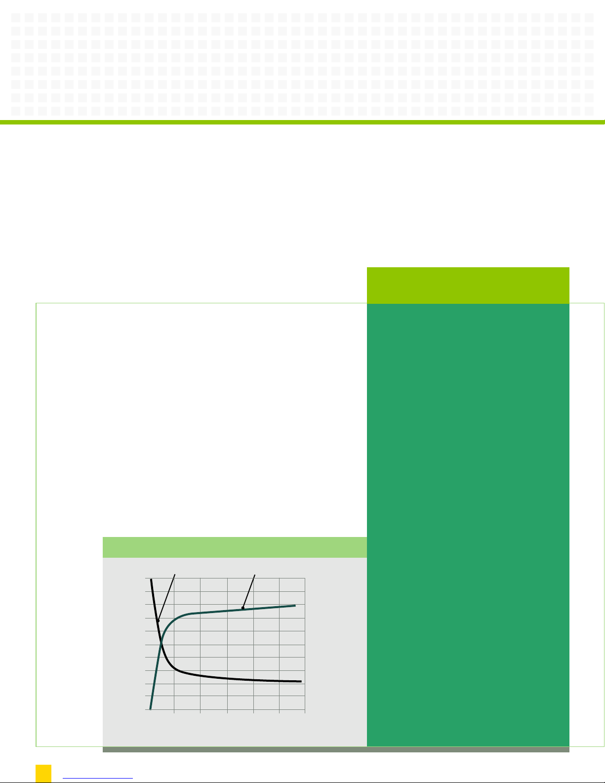
Typical Hybrid Advantage Surge Current Sharing Data
Hy
0 5,000 10,000 15,000 20,000 25,000 30,000
Total Surge Current (Amperes)
Percentage of Surge Current (%)
100.0
90.0
80.0
70.0
60.0
50.0
40.0
30.0
20.0
10.0
0.0
e
odul
AD M
d S
i
br
rc
e
t
In
tor MOV Module
p
e
The Liebert Answer:
The transitional method
Our answer lies in a two-part design
that actively disconnects the nominally
close components during a sustained
overvoltage and transitions from a
sensitive SAD circuit to a hardier MOV
array when subjected to damaging
transient levels.
First, a solid state comparator network
actively switches the SAD components out
of the transient control circuit when
exposed to line voltages in excess of their
Maximum Continuous Operating Voltage
(MCOV). While SAD components are
removed from the system, an appropriately
sized transient control network is available
for continued protection. During this
t phase, the nominal levels are
onnec
c
is
d
continually monitored until the system
voltage is stable, at which point the SAD
ght back on line
u
o
uit is br
irc
c
Second, a regulated amount of high-
nergy surge current is transitioned to
e
ondary MOV suppression modules.
ec
the s
This is accomplished through an
tching network utilizing a
a
e m
anc
ped
im
series of controlled copper geometries in
conjunction with custom engineered
nergy component
-e
gh
ge/hi
a
olt
-v
gh
hi
distribution. This ultimately limits the
amount of high-energy surge current
through the SAD module to an acceptable
evel and diverting the remaining surge
l
current through the MOV module.
.
2
Page 3
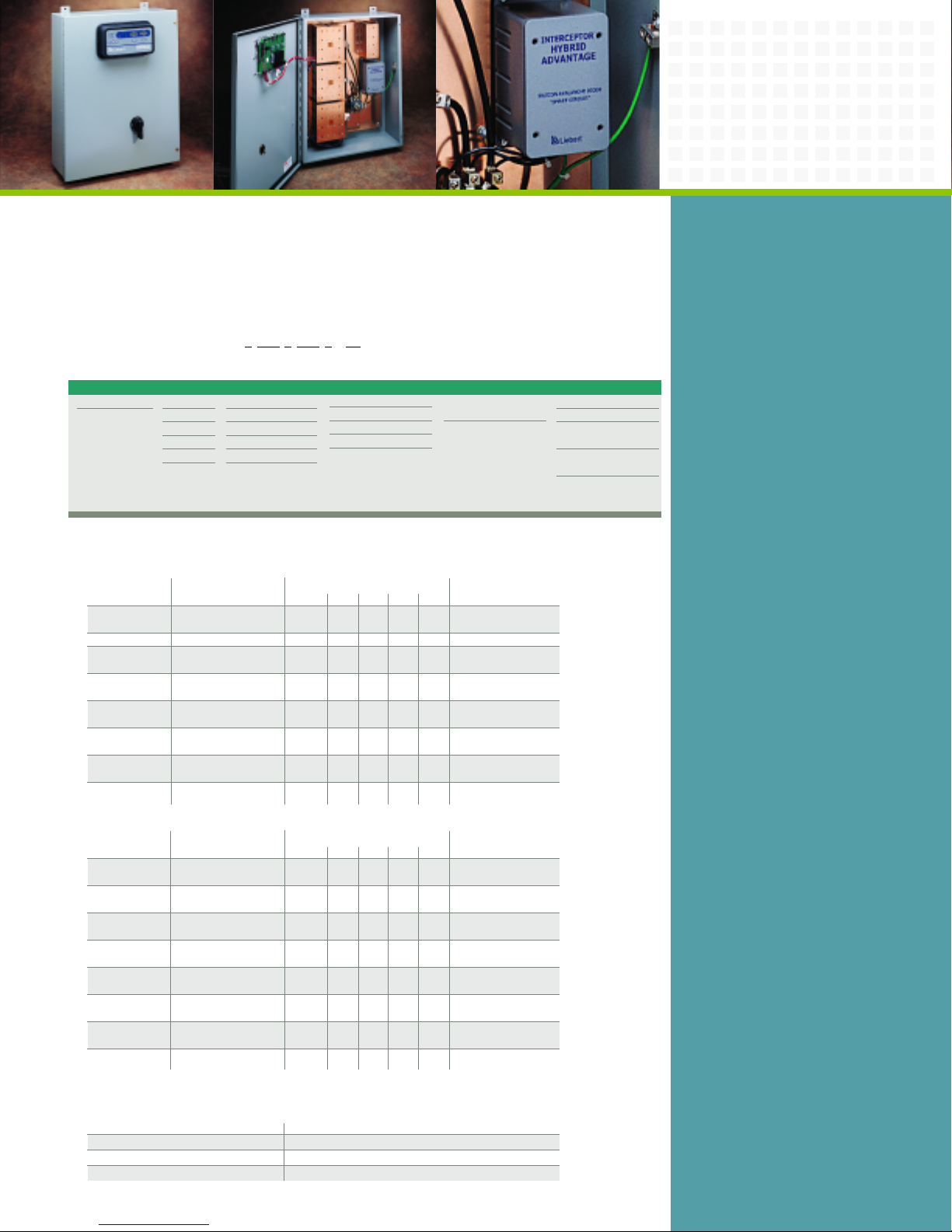
ebert Hybrid Advantage features
The Li
ast response time of the Silicone
the f
valanche Diode (SAD).
A
Specifying The Appropriate Model
All model numbers begin with a prefix. Use Chart A to build your Liebert Hybrid
dvantage starting with the SAD Surge Energy column. Moving left to right, choose the
A
correct configuration from each column for your application. Your completed model
number should look similar to the example below:
Example Part Number: H 2 120 Y 444 R - 03
Chart A
AD Surge Energy
S
250J
1
2 500J
-N Voltage
L
120V
120
208 208V
230V
230
240V
240
277 277V
480V
480
onfiguration
C
Single Phase L-N
N
L Single Phase L-L
Split Phase
S
3 Phase Wye
Y
D 3 Phase Delta
3 Phase Hi-Leg
H
e Current Rating
Surg
111 250kA Per Phase
320kA Per Phase
222
400kA Per Phase
333
444 750kA Per Phase
onnection Type
C
“blank” Compression
R
ugs
L
Rotar y
Disconnect
Liebert Hybrid Advantage Models
Medium Exposure Units
Model Configuration Surge Current Capability (kAmps) Dimensions* (inches)
H1/H2xxxS111 Split Single Phase 250 125 125 125 20 x 16 x 9
H1/H2xxxY111 Three Phase Wye 250 125 125 125 20 x 16 x 9
H1/H2xxxD110 Three Phase Delta 250 125 125 20 x 16 x 9
H1/H2xxxH111 Three Phase Delta 250 125 125 125 20 x 16 x 9
H1/H2xxxS222 Split Single Phase 320 160 160 160 24 x 20 x 9
H1/H2xxxY222 Three Phase Wye 320 160 160 160 24 x 20 x 9
H1/H2xxxD220 Three Phase Delta 320 160 160 24 x 20 x 9
H1/H2xxxH222 Three Phase Delta 320 160 160 160 24 x 20 x 9
High Exposure Units
Model Configuration Surge Current Capability (kAmps) Dimensions* (inches)
H1/H2xxxS333 Split Single Phase 400 200 200 200 24 x 24 x 9
H1/H2xxxY333 Three Phase Wye 400 200 200 200 24 x 24 x 9
H1/H2xxxD330 Three Phase Delta 400 200 200 24 x 24 x 9
H1/H2xxxH333 Three Phase Delta 400 200 200 200 24 x 24 x 9
H1/H2xxxS444 Split Single Phase 750 375 375 375 30x 24 x 9
H1/H2xxxY444
H1/H2xxxD440 Three Phase Delta 750 375 375 30x 24 x 9
H1/H2xxxH444 Three Phase Delta 750 375 375 375 30x 24 x 9
*Optional Disconnect Doesn’t Change Dimensions
(250kAmp and 320kAmp current capacity units)
Phase L-G L-L L-N N-G H x W x D
3 wire and ground
3 wire and ground
Hi-Leg, 4 wire and ground
3 wire and ground
4 wire and ground
3 wire and ground
Hi-Leg 4 wire and ground
(400kAmp and 750kAmp current capacity units)
Phase L-G L-L L-N N-G H x W x D
3 wire and ground
4 wire and ground
e and ground
4 wir
eg, 4 wire and ground
-L
Hi
3 wire and ground
ee Phase Wye 750 375 375 375 30x 24 x 9
Thr
4 wir
3 wire and ground
Hi-Leg 4 wire and ground
e and gr
und
o
onitoring Options
M
LED
01
04 LED, Alarm
LED, Surge
05
ounter
C
06 LED, Alarm,
ge Counter
Sur
03 LED, Alarm, Dual
Surge Counters
At a Glance
n
Unique "Surge Current Transition
Circuit" allows for seamless
transition from primary (SAD
technology) to secondary
(MOV array technology)
suppression system. A true,
shared suppression system.
n
Industry’s only Active Disconnect
System protects against system
failure and degradation due to
overvoltages.
n
Lowest UL 1449 clamping voltages
achieved—330VAC line to neutral
for a 120/208V Wye unit.
n
Technology of choice for speed,
allowing picosecond response time.
n
All surge suppression components
used are computer tested and
matched. SAD’s are matched to +/1% and MOVs are matched to 1 volt
for optimum reliability and long life.
n
Matched low impedance buss
system for both SAD and MOV
modules.
n
Liebert Hybrid Advantage builds
pon industry standard
u
Interceptor® Series design. Unique
benefits include:
— Patented component level
ding neutral
ing — inc
or
monit
to ground.
Unique sand-packed silver fuse
—
network UL Rated at 300kAIC
for safety.
t surge current capability
s
ghe
Hi
—
vi
and sur
ear warranty on parts and
10-y
—
5-year on-site labor, backed by
Emerson Power Service.
lu
y in the industry.
lit
i
b
a
v
Nominal Voltage Codes
Split Single Phase, 3 Wire plus Ground 120/240
Three Phase Wye, 4 Wire plus Ground 120/208, 230/400, 277/480
e Delta, 3 Wire plus Ground 208, 240, 400, 480
s
a
h
ee P
Thr
hase Delta Hi-Leg, 4 Wire plus Ground 120/240
ee P
Thr
Note: For other voltage configurations not listed, please consult factory.
(substitute for xxx to complete model number)
3
Page 4

Emerson Network Power.
The global leader in enabling Business-Critical Continuity.
EmersonNetworkPower.com
AC Power Systems
Connectivity
DC Power Systems
Embedded Power
Integrated Cabinet Solutions
Outside Plant
Power Switching & Controls
Precision Cooling
Site Monitoring
Surge & Signal Protection
Services
Liebert Corporation
1050 Dearborn Drive
P.O. Box 29186
Columbus, Ohio 43229
800 877 9222 Phone (U.S. &
Canada Onl
y)
614 888 0246 Phone (Outside U.S.)
614 841 6022
FAX
Via
Leonardo Da Vinci 8
Zona Industriale Tognana
35028 Piove Di Sacco (PD)
Italy
39 049 9719 111 Phone
39 049 5841 257 FAX
Emerson Network Power Asia Pacific
7/F., Dah Sing Financial Centre
108 Gloucester Rd, Wanchai
Hong Kong
852 25722201 Phone
852 28029250 FAX
liebert.com
Technical Support
800 288 6169 Toll-Free
607 724 2484 Phone
607 722 8713 Fax
Specifications
Connection Means Parallel Connected
gency Listing UL 1449 Listed (Second Edition), UL 1283, CUL
A
Protection Modes All modes standard (L-N, L-G, N-G, L-L); Optional – any combination
Surge Current Capacity 250 to 750kAmps per phase depending on model
imary Stage Joule H1 Models – 250 Joules
Pr
ating (L-N) per phase H2 Models – 500 Joules
R
EMI/RFI Filtering 41 dB at 100 KHz, 31 dB at 1 MHz, 35 dB at 10 MHz, 53 dB at 100 MHz
Response Time Picosecond range
epetitive Surge 15,000 - 120,000 10kA Category C3 surges per phase depending on model
R
Enclosure NEMA 12 standard Optional - NEMA 3R, 4, 4X and caseless
Line Frequency 47-63 Hertz
Line Voltage +/-15% nominal
Temperature -40 to +60 degrees C
Relative Humidity 0 to 95% noncondensing
Altitude 0 to 18,000 feet
Audible noise Less than 45 dBa
Warranty 10-years parts, 5-year labor
Standard Features Unit status indicators, Dual, isolated form C dry contacts
Optional Features Integral disconnect, Audible alarm, Transient counter – single or dual
While every precaution has been taken to ensure accuracy and
c
om
pleteness in this literature, Liebert Corporation assumes no
responsibility, and disclaims all liability for damages resulting
from use of this information or for any errors or omissions.
© 2005 Liebert Corporation. All rights reserved throughout
the world. Specifications subject to change without notice.
All names referred to are trademarks or registered trademarks
of their respective owners.
ebert and the Liebert logo are registered trademarks
® Li
f the Li
o
e
tion.
a
por
or
t C
r
be
Emerson Network Power and the Emerson Network Power logo are trademarks and service marks of Emerson Electric Co. ©2005 Emerson Electric Co.
SL-22060 (R3/06) Printed in USA
 Loading...