

Page 1
Instruction Manual
HAS8xE-IM-A TEX
08/2004
Instruction Manual
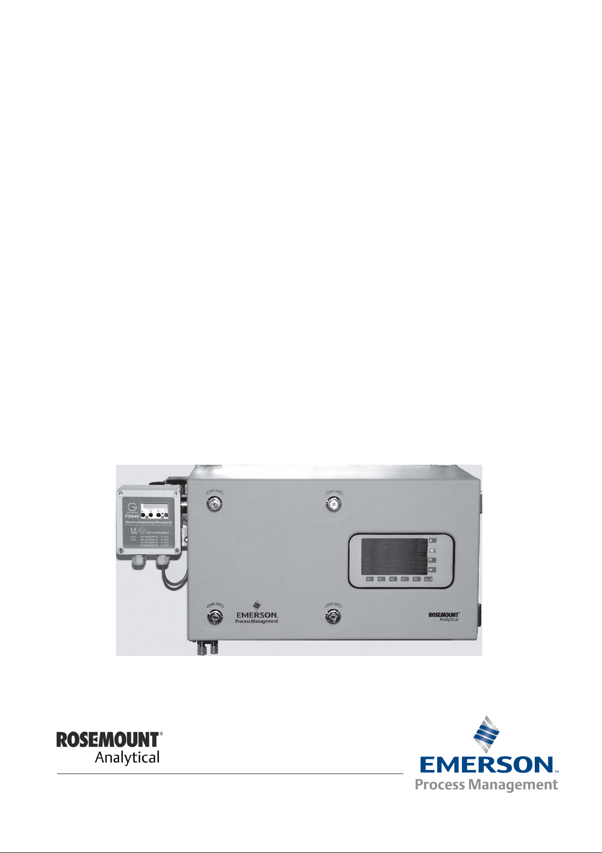
BINOS 100 F & MLT 2
Addendum for Pressurized Analyzers
intended to be used in
Hazardous Areas classified Zone 2
rd
Edition 08/2004
3
www.EmersonProcess.com
Page 2
BINOS 100 F & MLT 2 Addendum for Zone 2 Instruction Manual
HAS8XE-IM-ATEX
08/2004
ESSENTIAL INSTRUCTIONS
READ THIS P AGE BEFORE PROCEEDING!
Emerson Process Management (Rosemount Analytical) designs, manufactures and test s
its products to meet many national and international standards. Because these instruments
are sophisticated technical products, you MUST properly install, use, and maintain
them to ensure they continue to operate within their normal specifications. The following
instructions MUST be adhered to and integrated into your safety program when installing,
using and maintaining Emerson Process Management (Rosemount Analytical) products.
Failure to follow the proper instructions may cause any one of the following situations to
occur: Loss of life; personal injury; property damage; damage to this instrument; and warranty
invalidation.
• Read all instructions prior to installing, operating, and servicing the product.
• If you do not understand any of the instructions, contact your Emerson Process
Management (Rosemount Analytical) representative for clarification.
• Follow all warnings, cautions, and instructions marked on and supplied with the product.
• Inform and educate your personnel in the proper installation, operation, and
maintenance of the product.
• Install your equipment as specified in the Installation Instructions of the appropriate
Instruction Manual and per applicable local and national codes. Connect all products
to the proper electrical and pressure sources.
• T o ensure proper performance, use qualified personnel to install, operate, update, program,
and maintain the product.
• When replacement parts are required, ensure that qualified people use replacement parts
specified by Emerson Process Management (Rosemount Analytical). Unauthorized parts
and procedures can affect the product’s performance, place the safe operation of your
process at risk, and VOID YOUR W ARRANTY. Look-alike substitutions may result in fire,
electrical hazards, or improper operation.
• Ensure that all equipment doors are closed and protective covers are in place, except
when maintenance is being performed by qualified persons, to prevent electrical
shock and personal injury.
The information contained in this document is subject to change without notice. Misprints
reserved.
1st Edition 11/2003 2nd Edition 01/2004
3rd Edition 08/2004
© 2003-2004 by Emerson Process Management
Emerson Process Management
GmbH & Co. OHG
Industriestrasse 1
D-63594 Hasselroth
Germany
T +49 (0) 6055 884-0
F +49 (0) 6055 884-209
Internet: www.EmersonProcess.com
Page 3

ATEX Instruction Manual
HAS8xE-IM-ATEX
January 2004
The purpose of this manual is to provide additional information
concerning the components, functions, installation and maintenance of
EEx p pressurized MLT 2 and BINOS
installed and operated at hazardous locations, classified Zone 2, to
measure FLAMMABLE, but NON-EXPLOSIVE gases or gas mixtures.
The user should become thoroughly familiar with the operation of this
equipment before operating it.
Some sections may describe equipment not used in your configuration.
This ATEX instruction manual is a supplement to the analyzers standard
instruction manual! In addition to this manual, the manuals of all devices
necessary for operating the system must be observed. Read all manuals
completely to be familiar with the operation of this equipment at
hazardous locations.
PREFACE
100 F analyzers intended to be
MLT 2 / BINOS 100 F
Some technical specifications in this manual may be different to those
in the associated manuals for the analyzers and additional equipment.
In this case the technical specifications listed in this manual are valid
only.
Emerson Process Management Manufacturing GmbH & Co. OHG
P - 1
Page 4
MLT 2 / BINOS 100 F
The following definitions apply to WARNINGS, CAUTIONS and NOTES found
throughout this publication.
ATEX Instruction Manual
HAS8xE-IM-ATEX
January 2004
DEFINITIONS
Highlights an operation or
maintenance procedure,
practice, condition,
statement, etc. If not strictly
observed, could result in
injury, death, or long-term
health hazards of personnel.
Highlights an essential operating
procedure, condition or statement.
Highlights an operation or
maintenance procedure,
practice, condition,
statement, etc. If not strictly
observed, could result in
damage to or destruction of
equipment, or loss of
effectiveness.
NOTE
Emerson Process Management Manufacturing GmbH & Co. OHGP - 2
Page 5
ATEX Instruction Manual
HAS8xE-IM-ATEX
January 2004
MLT 2 / BINOS 100 F
IMPORTANT
SAFETY INSTRUCTIONS
SAFETY SUMMARY
If this equipment is used in a manner not specified in these instructions, protective
systems may be impaired.
PRODUCTS DESCRIBED IN THIS MANUAL SHALL NOT BE
SUPPLIED WITH EXPLOSIVE GASES!
PRODUCTS DESCRIBED IN THIS MANUAL ARE NOT
DESIGNED FOR USE IN ANY LIFE SUPPORT AND/OR
SAFETY EQUIPMENT WHERE FAILURE TO PERFORM CAN
REASONABLY BE EXPECTED TO RESULT IN PERSONAL
INJURY OR DEATH.
AUTHORIZED PERSONNEL
To avoid loss of life, personal injury and damage to this equipment and on-site property,
do not operate or service this instrument before reading and understanding this
instruction manual and receiving appropriate training.
SAVE THESE INSTRUCTIONS.
Emerson Process Management Manufacturing GmbH & Co. OHG
P - 3
Page 6

MLT 2 / BINOS 100 F
TERMS USED IN THIS MANUAL
ATEX
Directive 94/9/EC, commonly called the
ATEX („Atmosphères Explosibles“)
products directive.
Area Classification
ATEX Instruction Manual
HAS8xE-IM-ATEX
January 2004
Zone 1
Where ignitable concentrations of
flammable gases can exist some of the time
under normal operating conditions.
(A guideline value [not part of a standard ]
is 10 to 1.000 hours per year.)
Equipment to be used in Zone 1 has to be
classified Category 2.
Explosion Protection
External Explosion Protection
The „External explosion protection“ serves
to prevent penetration of explosive gas
mixtures into the analyzer enclosure. In
addition it avoids ignition on the surface. For
this reason the analyzer is purged with
protective gas and held at an internal
overpressure compared to the surrounding
atmosphere.
Zone 2
Where ignitable concentrations of
flammable gases are not likely to exist under
normal operating conditions.
(A guideline value [not part of a standard ] is
less than 10 hours per year.)
Equipment to be used in Zone 2 has to be
classified Category 3.
Internal Explosion Protection
The „Internal explosion protection“ serves to
prevent ignition of gas being present in the
analyzer’s Containment System (CS;=
sample gas path).
Dependent on the gas composition several
options are available:
None required (if gas is noncombustible),
dilution by purge gas or/and internal
overpressure of the analyzer’s enclosure
compared to the CS.
Containment System
The part of the analyzer containing the gas that may constitute an internal source of release.
Lower Explosion Limit (LEL)
Volume ratio of flammable gas in air below
which an explosive gas atmosphere will not
be formed: the mixture of gas and air lacks
sufficient fuel (gas) to burn.
Upper Explosion Limit (UEL)
Volume ratio of flammable gas in air above
which an explosive gas atmosphere will not
be formed: the mixture of gas and air is too
rich in fuel (deficient in oxygen) to burn.
Emerson Process Management Manufacturing GmbH & Co. OHGP - 4
Page 7

ATEX Instruction Manual
HAS8xE-IM-ATEX
January 2004
MLT 2 / BINOS 100 F
Terms used in this manual
Flammable Gas(es)
Gases and gas mixtures are assigned to be
flammable if they might become ignitable
when in a mixture with air.
Protective Gas
Air or inert gas used for purging and
maintaining an overpressure and, if
required, dilution.
Pre-Purging
The pre-purging phase serves to remove any
combustible gas out of the analyzer’s
enclosure prior to switching on the analyzer.
During this time the housing is purged with
5 times its own volume.
Explosive Gas(es)
Gases and gas mixtures are assigned to be
explosive if they consist of a flammable gas
in a mixture with air and the concentration is
inbetween the explosive limits.
Dilution
The continuous supply of a protective gas,
after purging, at such a rate that the
concentration of a flammable mixture inside
the pressurized enclosure is maintained at
a value outside the explosive limits except
in a dilution area.
Pressurization Modes
Pressurization mode „Continuous
Flow“
In EEx p „continuous flow mode“ the
protective gas flows with higher rates
through the enclosure. Flow rates are
calculated to hold an overpressure of > 1
mbar compared to atmospheric.
Emerson Process Management Manufacturing GmbH & Co. OHG
Pressurization mode „Leakage
Compensation“
In EEx p „leakage compensation mode“ just
as much protective gas is used to hold an
overpressure of > 1 mbar compared to
atmospheric.
P - 5
Page 8

MLT 2 / BINOS 100 F
ATEX Instruction Manual
HAS8xE-IM-ATEX
January 2004
Emerson Process Management Manufacturing GmbH & Co. OHGP - 6
Page 9

ATEX Instruction Manual
HAS8xE-IM-ATEX
January 2004
MLT 2 / BINOS 100 F
TABLE OF CONTENTS
Preface P-1
Definitions ..................................................................................................................... P-2
Safety Instructions ...................................................................................................... P-3
Terms used in this manual ........................................................................................... P-4
SECTION 1
Technical Description 1-1
1-1 Application and Principle of Operation .......................................................... 1-1
1-2 unused .............................................................................................................. 1-2
1-3 Specification .................................................................................................... 1-3
1-3-1 Installation Site ................................................................................................... 1-3
1-3-2 Explosion Protection .......................................................................................... 1-3
1-3-3 Pressurization Conditions ................................................................................... 1-3
1-3-4 Purge Gas Conditions ........................................................................................ 1-4
1-3-5 Sample Gas Conditions ..................................................................................... 1-5
1-3-6 Differential Pressure Monitoring ......................................................................... 1-5
1-4 Additional Safety Measures ............................................................................ 1-6
SECTION 2
Installation 2-1
2-1 General ............................................................................................................. 2-1
2-2 Installation of the Unit...................................................................................... 2-1
2-3 Dimensional Drawings .................................................................................... 2-2
2-3-1 Single Enclosure Analyzer .................................................................................. 2-2
2-3-2 Dual Enclosure Analyzer ..................................................................................... 2-4
2-4 Connection of Sample Gas and Protective Gas (Purge Gas) ....................... 2-6
2-4-1 Hints on Flammable Gases ................................................................................ 2-7
2-4-2 MLT 2 Gas Flow Diagrams ................................................................................. 2-8
2-4-3 BINOS® 100 F Gas Flow Diagrams .................................................................. 2-10
2-5 Safety Device Settings .................................................................................. 2-13
2-6 Special Remarks and Instructions ............................................................... 2-13
2-7 Electrical Connections .................................................................................. 2-14
2-7-1 Cable Gland Assembly Instruction for Shielded Cables ..................................... 2-14
2-7-2 Mains Connection............................................................................................. 2-15
2-7-2-1 Purge System .................................................................................................. 2-15
2-7-2-2 Analyzer ........................................................................................................... 2-17
2-7-3 Pressurization System Alarm Contacts ............................................................. 2-17
2-7-4 Differential Pressure Switch(es) ....................................................................... 2-18
Emerson Process Management Manufacturing GmbH & Co. OHG
i - 1
Page 10

ATEX Instruction Manual
HAS8xE-IM-ATEX
MLT 2 / BINOS 100 F
January 2004
SECTION 3
Startup 3-1
3-1 Final Check ...................................................................................................... 3-1
3-2 Switching On .................................................................................................... 3-1
SECTION 4
Maintenance 4-1
4-1 Maintenance Interval ....................................................................................... 4-1
4-2 Gasanalyzer ..................................................................................................... 4-1
4-3 Pressurization Systems and Other Additional Equipment ........................... 4-2
4-4 Verifications and Tests on Modified or Repaired Electrical Apparatus ....... 4-2
4-4-1 Preparations ...................................................................................................... 4-2
4-4-2 Overpressure Test .............................................................................................. 4-3
4-4-3 Leakage Test ..................................................................................................... 4-3
4-4-4 Removal of Modifications ................................................................................... 4-4
APPENDIX A-1
A-1 Declarations .....................................................................................................A-1
A-2 Circuit Diagrams .............................................................................................. A-3
A-2-1 MLT 2, single ...................................................................................................... A-3
A-2-2 MLT 2, dual ......................................................................................................... A-7
A-2-3 BINOS® 100 F .................................................................................................. A-11
Emerson Process Management Manufacturing GmbH & Co. OHGi - 2
Page 11

ATEX Instruction Manual
HAS8xE-IM-ATEX
January 2004
SECTION 1
Technical Description
1-1 Application and Principle of Operation
MLT 2 / BINOS 100 F
The gas analyzers of type BINOS 100 F
and MLT 2 are intended to measure gas
components within gas mixtures. In
combination with an approbriate certified
purge system (protection method
„Pressurized Enclosure“ EEx p) they can be
installed and operated in hazardous areas
of Zone 2.
Pressurization acts as external explosion
protection and prevents external explosive
atmosphere to penetrate into the analyzer
by holding the enclosure at an overpressure
compared to the surrounding
The type of purge system used varies
dependent on the area where the analyzer
is intended to be installed. Both systems
offer two modes of operation:
• EEx p with continuous flow
and
• EEx p with leakage compensation.
Dependent on the sample gas composition
it may be necessary to take care of internal
explosion protection which refers to the
sample gas path (containment system) in
the analyzer.
One of the following protection methods is
used:
• Nonflammable gases and gas
mixtures below the LEL: It must be
ensured that the sample gas in the
containment system always remains
below the lower explosive limit!
• Flammable gases and gas mixtures
may be analyzed when the sample gas
is diluted below ¼ LEL outside the
analyzer, so the resulting sample gas
is to be categorized „nonflammable“.
The diluting system must ensure that the
gas in the containment system always
remains below ¼ LEL.
• Flammable gases and gas mixtures
may be analyzed when the analyzer
enclosure has an internal overpressure
of > 50 Pa over the pressure in the
containment system. To ensure this
condition a differential pressure switch
is used and connected between
containment system and analyzer
enclosure. In case the pressure
decreases below the level of 50 Pa the
switch is activated and may be used to
activate an alarm or analyzer shut-off.
If more than one switch is needed
because more than one flammable gas
is supplied to the analyzer, the contacts
of these switches have to be connected
in series. Purge medium may be inert
gas or air. Flame arrestors are required
for all gas inlets and outlets carrying
flammable gases.
• Explosive gases must not be
connected to the analyzer!
Emerson Process Management Manufacturing GmbH & Co. OHG
1 - 1
Page 12

MLT 2 / BINOS 100 F
1-2 Unused
ATEX Instruction Manual
HAS8xE-IM-ATEX
January 2004
1-2 Instrument Layout
Emerson Process Management Manufacturing GmbH & Co. OHG1 - 2
Page 13

ATEX Instruction Manual
HAS8xE-IM-ATEX
January 2004
1-3 Specification
1-3 Specification
1-3-1 Installation Site
Hazardous area: Zone 2 (Category 3),
1-3-2 Explosion Protection
MLT 2 / BINOS 100 F
Concepts:
Category 3: Pressurized enclosure
(EEx p) using simplified
purge with either leakage
compensation mode or
continuous flow
Temperature class: T4
1-3-3 Pressurization Conditions
Volume of pressurized enclosure:
single enclosure: approx. 56 l
dual enclosure: approx. 112 l
Pre-purge phase:
Duration:
single enclosure: 5 minutes
dual enclosure: 17 minutes
Options: Intrinsically safe (EEx i) digital,
analog, network or Foundation
Fieldbus outputs.
Intrinsically safe (EEx i) paramagnetic Oxygen sensor or thermal conductivity sensor.
Applicable Standards:
EN 50014:1997 + amendments 1 & 2,
EN 50016:1995,
EN 50020:1994
Flow of protective gas:
single enclosure: 8 Nm³/h
dual enclosure: 7 Nm³/h
Minimum overpressure during
operation:
1 mbar against external Ex Zone and
>50 Pa against Containment System if
flammable gases are supplied.
Emerson Process Management Manufacturing GmbH & Co. OHG
1 - 3
Page 14
MLT 2 / BINOS 100 F
1-3-4 Purge Gas Conditions
1-3-4 Purge Gas Conditions
Purge gas: • Inert gas (e.g. Nitrogen)
• Air (from an ex-free zone)
Temperature: As ambient, but min. 20 °C to 35 °C.
Medium has to be dry and free from
dust, oil, corrosive or aggressive
components!
Input pressure at
inlet of EEx p device: • 3,000 to 4,000 hPa (3 to 4 bar)
ATEX Instruction Manual
HAS8xE-IM-ATEX
January 2004
Minimum internal
overpressure of
the enclosure: • 1 mbar
Maximum internal
overpressure of
the enclosure: • 25 mbar
Pre-purging phase Single enclosure analyzer Dual enclosure analyzer
Duration of
pre-purging phase: 5 min. 17 min.
Flow rate during
pre-purging phase: 8 Nm³/h 7 Nm³/h
(= 133.4 l/min.) (= 117 l/min.)
Flow rate during
pre-purging phase 22 Nm³/h 22 Nm³/h
(@ 25 mbar overpressure): (= 367 l/min.) (= 367 l/min.)
Emerson Process Management Manufacturing GmbH & Co. OHG1 - 4
Page 15

ATEX Instruction Manual
HAS8xE-IM-ATEX
January 2004
MLT 2 / BINOS 100 F
1-3-5 Sample Gas Conditions
1-3-5 Sample Gas Conditions
Applicable gases: Nonflammable gases or
gas mixtures which always Flammable gases
remain below LEL
Maximum sample
gas pressure: atmospheric or atmospheric or
<1500 hPa at normal <1500 hPa at normal
atmospheric pressure, atmospheric pressure,
dependend on gas dependend on gas
measuring principle measuring principle
and
overpressure < 13 mbar
against surrounding atmosphere
Sample gas flow: for all sample gases refer to the corresponding analyzer data sheet
1-3-6 Differential Pressure Monitoring
For analyzers connected to flammable gases (either sample gas or span gas) the operator
needs to ensure that the pressure within the containment system always remains at minimum
50 Pa below the pressure within the analyzer enclosure. This ensures that in case of a leak the
flammable gas does not enter the enclosure.
An additional differential pressure switch is provided to monitor the pressure difference:
In case the pressure difference decreases below 50 Pa the contact opens.
It is the user’s responsiblity how to use the signal within his system:
The limit of 50 Pa is the least permissible value given by the standards, higher values are
acceptable, too.
Flame arrestors are required for gas inlets and outlets.
Electrical and mechanical connections are shown in section 2 „Installation“.
Emerson Process Management Manufacturing GmbH & Co. OHG
1 - 5
Page 16

MLT 2 / BINOS 100 F
1- Additional Safety Measures
1-4 Additional Safety Measures
• Exhaust gas lines must end outside the
hazardous area at a safe point. Sample
gas lines may be returned to the
sampling point.
• If gas exhaust lines end within the
hazardous area gas inlet and outlet
have to be equipped with flame
arrestors.
• The maximum permissible gas
pressure depends on the type of
connected gas. See section 1-3-5 for
detailed information.
ATEX Instruction Manual
HAS8xE-IM-ATEX
January 2004
Emerson Process Management Manufacturing GmbH & Co. OHG1 - 6
Page 17
ATEX Instruction Manual
HAS8xE-IM-ATEX
January 2004
MLT 2 / BINOS 100 F
SECTION 2
Installation
Before starting to install this equipment, read the corresponding sections of the
analyzer’s instruction manual and the manuals of the additional equipment!
Failure to follow the safety instructions could result in serious injury or death.
2-1 General
Proper functioning of the Emerson Process
Management gas analyzers depends on
proper installation. All procedures in this
section, in the corresponding sections of the
analyzer instruction manual and the manuals
of the attached safety devices must be
followed carefully.
2-2 Installation of the Unit
Install the assembled unit as described in
the analyzer’s instruction manual: Refer to
the dimensional drawings in this manual
(fig. 2-1a/b and 2-2a/b) to ensure the
designated location is dimensioned
sufficiently.
The weight of an assembled unit may be up
to approx. 40 kg incl. pressurization system.
Take care to use anchors and
bolts specified to be used for
the weight of the units!
Take care the wall the unit is
intended to be installed at is
solid and stable to hold the
units!
Emerson Process Management Manufacturing GmbH & Co. OHG
2 - 1
Page 18

MLT 2 / BINOS 100 F
2-3 Dimensional Drawings
2-3 Dimensional Drawings
2-3-1 Single Enclosure Analyzer
ATEX Instruction Manual
HAS8xE-IM-ATEX
January 2004
Standard version w/o pressurization system
Fig. 2-1a
Single enclosure analyzer (dimensions in mm)
Emerson Process Management Manufacturing GmbH & Co. OHG2 - 2
Page 19

ATEX Instruction Manual
HAS8xE-IM-ATEX
January 2004
MLT 2 / BINOS 100 F
2-3-1 Single Enclosure Analyzer
with Category 3 pressurization system
Fig. 2-1b
Single enclosure analyzer (dimensions in mm)
Emerson Process Management Manufacturing GmbH & Co. OHG
2 - 3
Page 20

MLT 2 / BINOS 100 F
2-3-2 Dual Enclosure Analyzer
2-3-2 Dual Enclosure Analyzer
ATEX Instruction Manual
HAS8xE-IM-ATEX
January 2004
Standard version w/o pressurization system
Fig. 2-2a
Dual enclosure analyzer (dimensions in mm)
Emerson Process Management Manufacturing GmbH & Co. OHG2 - 4
Page 21

ATEX Instruction Manual
HAS8xE-IM-ATEX
January 2004
MLT 2 / BINOS 100 F
2-3-2 Dual Enclosure Analyzer
with Category 3 pressurization system
Fig. 2-2b
Dual enclosure analyzer (dimensions in mm)
Emerson Process Management Manufacturing GmbH & Co. OHG
2 - 5
Page 22

MLT 2 / BINOS 100 F
2-4 Connection of Sample Gas and Protective Gas (Purge Gas)
2-4 Connection of Sample Gas and
Protective Gas (Purge Gas)
ATEX Instruction Manual
HAS8xE-IM-ATEX
January 2004
When the analyzer with assembled EEx p
safety device has been fixed, connect the
gas lines according the diagram (fig. 2-3).
The following conditions must be observed
for trouble free operation:
• The operator must ensure the minimum
pressure of the protective gas at the
point of installation.
A pressure of 3,000 ... 4,000 hPa
(3...4 bar) must be applied to the
protective gas inlet of the EEx p safety
device.
• The EEx safety device is delivered with
fixed basic parameters. The minimum
purge gas pressure is preset to
14 mbar. Useful modifications such as
increasing the max. purge gas
pressure must only be done after
studying the appropriate sections of the
manual of the EEx p safety device.
• Flammable sample gas must not be
supplied to the analyzer until the prepurging phase has ended.
Emerson Process Management Manufacturing GmbH & Co. OHG2 - 6
Page 23

ATEX Instruction Manual
HAS8xE-IM-ATEX
January 2004
2-4-1 Hints on Flammable Gases
2-4-1 Hints on Flammable Gases
• When applying flammable gases (either
as sample gas or span gas) the
corresponding gas inlets and outlets
must be equipped with flame arrestors.
• To avoid internal release of flammable
gases the minimum pressure specified
for the pressurized enclosure is at least
50 Pa higher than the maximum
pressure specified for the containment
system. A differential pressure switch is
provided with the system to operate if
the pressure difference falls below
50 Pa.
MLT 2 / BINOS 100 F
The 50 Pa limit is the value
defined by the associated
standards. It is not allowed
to decrease this value but
higher values are allowed
and may be set dependent
on the application and differential pressure switch
used.
The purpose(s) for which the differential pressure switch is used (i.e. to activate
disconnection of power or to sound an alarm or otherwise maintain the safety
of the installation) is the responsibility of the user!
Take care of the possible formation of flammable mixtures due to the possibility
of air penetration into the containment system and the resulting additional
precautions that may be necessary.
Emerson Process Management Manufacturing GmbH & Co. OHG
2 - 7
Page 24

MLT 2 / BINOS 100 F
2-4-2 MLT 2 Gas Flow Diagrams
2-4-2 MLT 2 Gas Flow Diagrams
ATEX Instruction Manual
HAS8xE-IM-ATEX
January 2004
Fig. 2-3a
Gas Flow Diagram
Emerson Process Management Manufacturing GmbH & Co. OHG2 - 8
Page 25

ATEX Instruction Manual
HAS8xE-IM-ATEX
January 2004
2-4-2 MLT 2 Gas Flow Diagrams
2-4-2 MLT 2 Gas Flow Diagrams (cont’d)
MLT 2 / BINOS 100 F
Emerson Process Management Manufacturing GmbH & Co. OHG
Fig. 2-3b
Gas Flow Diagram
2 - 9
Page 26

MLT 2 / BINOS 100 F
2-4-3 BINOS® 100 F Gas Flow Diagrams
2-4-3 BINOS® 100 F Gas Flow Diagrams
ATEX Instruction Manual
HAS8xE-IM-ATEX
January 2004
Fig. 2-3c
Gas Flow Diagram
Emerson Process Management Manufacturing GmbH & Co. OHG2 - 10
Page 27

ATEX Instruction Manual
HAS8xE-IM-ATEX
January 2004
2-4-3 BINOS® 100 F Gas Flow Diagrams
2-4-3 BINOS® 100 F Gas Flow Diagrams (cont’d)
MLT 2 / BINOS 100 F
Emerson Process Management Manufacturing GmbH & Co. OHG
Fig. 2-3d
Gas Flow Diagram
2 - 11
Page 28

MLT 2 / BINOS 100 F
2-4-3 BINOS® 100 F Gas Flow Diagrams
2-4-3 BINOS® 100 F Gas Flow Diagrams
ATEX Instruction Manual
HAS8xE-IM-ATEX
January 2004
Fig. 2-3e
Gas Flow Diagram
Emerson Process Management Manufacturing GmbH & Co. OHG2 - 12
Page 29

ATEX Instruction Manual
HAS8xE-IM-ATEX
January 2004
2-5 Safety Device Settings
2-5 Safety Device Settings
MLT 2 / BINOS 100 F
The EEx safety device is delivered with fixed
basic parameters. The purge gas pressure
is preset to 14 hPa (rel.; for flammable
gases). Useful modifications such as
increasing the max. purge gas pressure
must only be done after studying the
appropriate sections of the manual of the
EEx p safety device.
2-6 Special Remarks and Instructions
It is not allowed to change
the internal purge medium
path.
The pressurization system is provided with
a bypass function to switch off the automatic
monitoring facility. It is therefore also
possible to switch on the pressurized system
with the housing door open for setting work
resp. to keep the analyzer powered even if
the front door is opened.
The use of this function is
intended for maintenance
purposes only!
This facility should however
only be used when it has
been ascertained that there is
no explosive atmosphere in
the vicinity of the unit (fire
safety certificate).
As the parameters are selected to be in
conformance with the type test results, some
of them are not allowed to be changed!
This applies to the pre-purge time, which is
adjusted to ensure a 5 times volume
exchange within the analyzer enclosure at a
preset purge medium flow!
When maintenance work has been finished
is has to be verified that the bypass is turned
off!
The pressurization system M code, preset
to 0001, must be replaced by an individual
code which must then be entered.
The pressurization system by-pass code,
preset to 0002, should for safety reasons
be replaced by an individual code, unequal
Zero.
Emerson Process Management Manufacturing GmbH & Co. OHG
2 - 13
Page 30

MLT 2 / BINOS 100 F
2-7 Electrical Connections
2-7 Electrical Connections
Installation of and connecting
the power supply lines and
signal lines is permitted to
qualified personnel only!
The standard EN 60079-14
„Electrical Installations in
Hazardous Areas“ and all
related standards have to be
observed.
Failure to follow the proper
instructions may cause any one
of the following situations to
occur: Loss of life; personal
injury; property damage;
damage to this instrument; and
warranty invalidation.
ATEX Instruction Manual
HAS8xE-IM-ATEX
January 2004
• All connections have to be done
according to the schematics delivered
together with the equipment.
• A mains switch or ciruit-breaker must be
provided at the building installation.
• The equipment enclosure must be
connected to an earthing or equipotential
bonding conductor.
• All cables introduced into the enclosure
must be kept as short as possible.
• The cable glands are designed to fix
single cables only, with diameters from 7
to 12 mm.
• Use only shielded cables for signal lines!
To ensure proper electromagnetic
compatibility (EMC) it is recommended
to follow the installation steps given
below.
2-7-1 Cable Gland Assembly Instruction for Shielded Cables
1. Strip the cable
insulation
2. Uncover the
shielding
3. Feed cable through
gland nut and into
fixing element
4. Put the shielding net
over the element the
way that it covers the
o-ring 2 mm.
Emerson Process Management Manufacturing GmbH & Co. OHG2 - 14
5. Stick the fixing
element into the
neck and fix the
gland.
Page 31

ATEX Instruction Manual
HAS8xE-IM-ATEX
January 2004
2-7-2 Mains Connection
MLT 2 / BINOS 100 F
2-7-2 Mains Connection
Recommended standard mains connection
is done by using separate cords for analyzer
and pressurization system.
This configuration allows to activate the
safety device indepently from the analyzer
to purge the analyzer enclosure before
switching on.
2-7-2-1 Purge System
Remove the pressurization system control
unit’s cover.
The mains power line cord has to be
connected to the terminals 7 (N) and 9 (L) ,
the PE conductor is connected to separated
terminals in the lower left corner ot the
enclosure (fig. 2-4).
In case of pressurization
failure the analyzer will not be
shut off!
If automatic shut off is
required an external switch
(relay), additional wiring and
use of alarm contacts is
needed!
Verify that the mains voltage
at the point of installation
meets the system nominal
voltage!
Re-install the cover!
PE terminals
Fig. 2-4
Terminal location pressurization system control unit
Emerson Process Management Manufacturing GmbH & Co. OHG
Terminal 9 (L; Hi)
Terminal 7 (N; Lo)
2 - 15
Page 32

MLT 2 / BINOS 100 F
2-7-2 Mains Connection
2-7-2-2 Analyzer
ATEX Instruction Manual
HAS8xE-IM-ATEX
January 2004
The mains power line cord has to be
connected to the terminals provided at the
analyzer enclosure’s inner left side, near the
EMC line filter (fig. 2-5).
Fig. 2-5
Terminal location inside analyzer
Verify that the mains voltage
at the point of installation
meets the analyzer nominal
voltage!
EMC line filter
Terminals
By default the analyzer has to be supplied
separatly to the pressurization unit. This
Omitting the pre-purge sequence
The pre-purging sequence can be refrained
if it is ensured that at the moment of
activating the analyzer the atmosphere
inside the enclosure and the appropriate
pipes is well below 25 % LEL.
allows to shut on the safety device for prepurging the analyzer, while this is still shut
off!
It is the responsibility of the
user to omit pre-purging!
Emerson Process Management Manufacturing GmbH & Co. OHG2 - 16
Page 33

ATEX Instruction Manual
HAS8xE-IM-ATEX
January 2004
2-7-3 Pressurization System Alarm Contacts
MLT 2 / BINOS 100 F
In this case the analyzer mains cord may be
connected to terminals 8 (L), 10 (N) and PE
of the pressurization unit instead of
connecting it to a mains outlet.
So only one single outlet is required for the
system.
2-7-3 Pressurization System Alarm Contacts
The pressurization control unit provides
alarm contacts which are widely
programmable.
Refer to the unit’s instruction manual for
information about available options and how
to setup the contacts.
In each case applies:
In case of pressurization
failure the analyzer will not be
shut off!
If automatic shut off is
required an external switch
(relay), additional wiring and
use of alarm contacts is
needed!
The purpose(s) for which the alarm contacts are used (i.e. to activate
disconnection of power or to sound an alarm or otherwise maintain the safety
of the installation) is the responsibility of the user!
Emerson Process Management Manufacturing GmbH & Co. OHG
2 - 17
Page 34

MLT 2 / BINOS 100 F
2-7-4 Differential Pressure Switch(es)
2-7-4 Differential Pressure Switch(es)
ATEX Instruction Manual
HAS8xE-IM-ATEX
January 2004
The contact of the differential pressure
switch is connected to terminals X30
installed inside the analyzer.
The contact opens if the differential pressure
decreases below 50 Pa.
To use this alarm contact the user must
connect his external monitoring system to
these terminals.
Refer to the schematics in appendix to see
how to connect the switch.
It is the responsibility of the user to
connect other circuitry than
specified for scanning the differential pressure switch.
Take into account the risk of igniting
flammable gas by sparking
contacts!
The contacts must be
connected to signal circuitry
(amplifier, relay) providing
output signals according
NAMUR resp. EN 50227 only.
The standard specifies all
essential data and operating
conditions.
Consult factory for
applicable circuitry which is
available from various
manufacturers.
The purpose(s) for which the differential pressure switch is used (i.e. to activate
disconnection of power or to sound an alarm or otherwise maintain the safety
of the installation) is the responsibility of the user!
Emerson Process Management Manufacturing GmbH & Co. OHG2 - 18
Page 35

ATEX Instruction Manual
HAS8xE-IM-ATEX
January 2004
MLT 2 / BINOS 100 F
SECTION 3
Startup
Startup can only be done properly by personnel being familiar with the contents
of all applicable manuals and related instructions!
Especially the warnings provided by the documentation have to be observed!
3-1 Final Check
Make sure that the analyzer and the related
pressurization system have been setup as
described in section 2 and all covers and
doors are closed and fixed.
All unused cable glands need to be sealed
using the supplied approved sealing plug
(part no. ETC00791; fig. 3-1)
Unused cable gland openings in the
enclosure need to be covered using a
special screw (part no. ETC 000790; fig. 3-2).
Fig. 3-1
Cable gland sealing plug
Use only the components listed
above as these are ATEX
approved for use in hazardous
areas!
3-2 Switching On
In a next step the analyzer may be powered
by opening the purge gas supply and
switching on the power supply.
Emerson Process Management Manufacturing GmbH & Co. OHG
Fig. 3-2
Cable gland hexagon socket screw sealing plug
3 - 1
Page 36

MLT 2 / BINOS 100 F
ATEX Instruction Manual
HAS8xE-IM-ATEX
January 2004
Emerson Process Management Manufacturing GmbH & Co. OHG3 - 2
Page 37

ATEX Instruction Manual
HAS8xE-IM-ATEX
January 2004
MLT 2 / BINOS 100 F
SECTION 4
Maintenance
After maintenance or replacement of parts concerning explosion protection an
authority on explosion protection has to verify that the analyzer still meets the
requirements for explosion protection before it is switched on again.
If parts essential for explosion protection are repaired they have to be routine
tested!
The authority has to issue a certificate for this and/or attach a test label to the
equipment before startup after maintenance or replacement of parts.
4-1 Maintenance Interval
To ensure the performance and safety of the
equipment it has to be checked on a regular
basis, at least once a year. Special care has
to be taken for the EEx p saftey device and
parts ensuring explosion protection (e.g.
gaskets).
4-2 Gasanalyzer
Refer to the associated manual for detailed
information on maintenance, replacement of
parts and how to carry out a containment
system leak test.
It is the operators/owners
responsibility to extend the
maintenance interval with
respect to negative
influences of gases or
environment on materials in
contact with the sample gas
or ensuring explosion
protection (e.g. gaskets).
Emerson Process Management Manufacturing GmbH & Co. OHG
4 - 1
Page 38

MLT 2 / BINOS 100 F
4-3 Pressurization Systems and
Other Additional Equipment
Refer to the associated manuals for detailed
information on maintenance and
replacement of parts.
4-4 Verifications and Tests on
Modified or Repaired Electrical
Apparatus
ATEX Instruction Manual
HAS8xE-IM-ATEX
January 2004
Modifications made on the electrical
apparatus affecting the integrity of the type
of protection or the temperature of the
apparatus shall be permitted only if the
modified apparatus is resubmitted to a
testing station.
4-4-1 Preparations
To do the routine tests the following steps
have to be performed:
• Disconnect the analyzer and the
pressurization unit from power.
• Seal the purge medium outlet at the
pressurization unit (1“ opening at the left
side).
• Disconnect the containment system
gas connectors from the external gas
lines.
• Disconnect one of the containment
system gas connectors inside the
analyzer and seal the other one.
In the case of repairs of electrical apparatus
affecting the type of protection, the parts
which have been repaired should be
subjected to new routine verifications and
tests. These test s need not necessarily be
made by the manufacturer.
(Remark: Now it must be possible set
the enclosure under pressure by
applying an external gas (e.g.
compressed air) to the gas connector.)
• Connect an external source of
compressed air as described in the
drawing on the next page (fig. 4-1). The
manometer needs to have a measuring
range of 50 to 100 mbar with a resolution
of 0.1 mbar. The flowmeter needs to
have a measuring range of 10 l/min,
resolution 0.1 l/min.
Emerson Process Management Manufacturing GmbH & Co. OHG4 - 2
Page 39

ATEX Instruction Manual
HAS8xE-IM-ATEX
January 2004
MLT 2 / BINOS 100 F
Fig. 4-1
Setup for routine tests
4-4-2 Overpressure Test
A pressure of 37.5 mbar (= 1.5 times the
maximum overpressure specified) has to be
applied to the pressurized enclosure. To do
this the following has to be performed:
• Carefully apply a pressure of 37.5 mbar
to the enclosure and hold this pressure
for a period of 2 minutes +/- 10 seconds.
The test is considered to be satisfactory if
no permanent deformation occures which
would invalidate the type of protection.
Keep the modifications to carry out the
leakage test (sec. 4-4-3).
4-4-3 Leakage Test
The leakage of the enclosure has to be
measured with an overpressure of 25 mbar
applied to the pressurized enclosure. To do
this the following steps have to be
performed:
• Make sure the modifications as
described in the section 4-4-1are still
existent.
• Apply an overpressure of 25 mbar to
the analyzer enclosure and take the
reading of the flow meter.
The test is considered to be satisfacotry if
the measured value is acceptable
compared to the following values.
Acceptable flow values are:
• all analyzers: 3 l/minute maximum
Emerson Process Management Manufacturing GmbH & Co. OHG
4 - 3
Page 40

MLT 2 / BINOS 100 F
4-4-4 Removal of Modifications
Remove all the modifications described in
section 4-4-1. Take special care of the gas
connections to be tightend.
ATEX Instruction Manual
HAS8xE-IM-ATEX
January 2004
Emerson Process Management Manufacturing GmbH & Co. OHG4 - 4
Page 41

ATEX Instruction Manual
HAS8xE-IM-ATEX
August 2004
A-1 Declarations
MLT 2 / BINOS 100 F
APPENDIX
Emerson Process Management Manufacturing GmbH & Co. OHG
A- 1
Page 42

MLT 2 / BINOS 100 F
ATEX Instruction Manual
HAS8xE-IM-ATEX
August 2004
A-1 Declarations
Emerson Process Management Manufacturing GmbH & Co. OHGA- 2
Page 43

ATEX Instruction Manual
HAS8xE-IM-ATEX
August 2004
MLT 2 / BINOS 100 F
A-1 Declarations
Emerson Process Management Manufacturing GmbH & Co. OHG
A- 3
Page 44

MLT 2 / BINOS 100 F
A-2 Circuit Diagrams
A-2-1 MLT 2, single
ATEX Instruction Manual
HAS8xE-IM-ATEX
August 2004
A-2 Circuit Diagrams
Emerson Process Management Manufacturing GmbH & Co. OHGA- 4
Page 45

ATEX Instruction Manual
HAS8xE-IM-ATEX
August 2004
MLT 2 / BINOS 100 F
A-2-1 MLT 2 Circuit Diagrams
Emerson Process Management Manufacturing GmbH & Co. OHG
A- 5
Page 46

MLT 2 / BINOS 100 F
A-2-1 MLT 2 Circuit Diagrams
ATEX Instruction Manual
HAS8xE-IM-ATEX
August 2004
Emerson Process Management Manufacturing GmbH & Co. OHGA- 6
Page 47

ATEX Instruction Manual
HAS8xE-IM-ATEX
August 2004
MLT 2 / BINOS 100 F
A-2-1 MLT 2 Circuit Diagrams
Emerson Process Management Manufacturing GmbH & Co. OHG
A- 7
Page 48

MLT 2 / BINOS 100 F
A-2-2 MLT 2 Circuit Diagrams
A-2-2 MLT 2, dual
ATEX Instruction Manual
HAS8xE-IM-ATEX
August 2004
Emerson Process Management Manufacturing GmbH & Co. OHGA- 8
Page 49

ATEX Instruction Manual
HAS8xE-IM-ATEX
August 2004
MLT 2 / BINOS 100 F
A-2-2 MLT 2 Circuit Diagrams
Emerson Process Management Manufacturing GmbH & Co. OHG
A- 9
Page 50

MLT 2 / BINOS 100 F
A-2-2 MLT 2 Circuit Diagrams
ATEX Instruction Manual
HAS8xE-IM-ATEX
August 2004
Emerson Process Management Manufacturing GmbH & Co. OHGA- 10
Page 51

ATEX Instruction Manual
HAS8xE-IM-ATEX
August 2004
MLT 2 / BINOS 100 F
A-2-2 MLT 2 Circuit Diagrams
Emerson Process Management Manufacturing GmbH & Co. OHG
A- 11
Page 52

MLT 2 / BINOS 100 F
A-2-2 BINOS® 100 F Circuit Diagrams
A-2-3 BINOS® 100 F
ATEX Instruction Manual
HAS8xE-IM-ATEX
August 2004
Emerson Process Management Manufacturing GmbH & Co. OHGA- 12
Page 53

ATEX Instruction Manual
HAS8xE-IM-ATEX
August 2004
A-2-2 BINOS® 100 F Circuit Diagrams
MLT 2 / BINOS 100 F
Emerson Process Management Manufacturing GmbH & Co. OHG
A- 13
Page 54

BINOS 100 F & MLT 2 Addendum Zone 2
WORLD HEADQUARTERS
ROSEMOUNT ANAL YTICAL EUROPE
Emerson Process Management
GmbH & Co. OHG
Industriestrasse 1
63594 Hasselroth
Germany
T 49 6055 884 0
F 49 6055 884209
Emerson Process Management
Rosemount Analytical Inc.
6565 P Davis Industrial Parkway
Solon, OH 44139 USA
T 440.914.1261
Toll Free in US and Canada 800.433.6076
F 440.914.1271
e-mail: gas.csc@EmersonProcess.com
www.raihome.com
GAS CHROMAT OGRAPHY CENTER
AND LATIN AMERICA
Emerson Process Management
Rosemount Analytical Inc.
11100 Brittmoore Park Drive
Houston, TX 77041
T 713 467 6000
F 713 827 3329
Instruction Manual
HAS8xE-IM-A TEX
08/2004
EUROPE, MIDDLE EAST AND AFRICA
Emerson Process Management
Shared Services Limited
Heath Place
Bognor Regis
West Sussex PO22 9SH
England
T 44 1243 863121
F 44 1243 845354
ASIA-PACIFIC
Emerson Process Management
Asia Pacific Private Limited
1 Pandan Crescent
Singapore 128461
Republic of Singapore
T 65 6 777 8211
F 65 6 777 0947
e-mail: analytical@ap.emersonprocess.com
© Emerson Process Management GmbH & Co. OHG 2007
 Loading...