

Page 1
Diesel Engine Fire Pump Controller
for Class 1, Division 2 Hazardous Locations
Page 2
Class 1, Division 2 hazardous locations, T3
temperature rating.
Firetrol® FTA1100H combined automatic and
manual Mark II based diesel engine fi re pump con-
trollers are intended for starting and monitoring fi re
pump diesel engines in Class1, Division 2 hazardous locations. The controllers have a temperature
rating of T3. They are available for use with 12 or
24 volt negative ground systems using lead acid or
Nickel-Cadmium batteries, and available with 10 or
20 amp charging circuits. The controller monitors,
displays and records fi re pump system information.
Metering
• The controller provides display of incoming
AC power line voltages.
• Total engine run time may be displayed.
• Pressure is displayed in PSI or Bars in 1 psi increments (0.1 bar). The controller is supplied
as standard with a 0-300 psi (0-20.7 bars)
stainless steel pressure transducer for fresh
water applications and optionally with a 0-600
psi (0-41.4 bars) pressure transducer.
Controllers can be ordered for copper corro-
sive applications.
• Battery voltages and charging currents are
displayed on the main screen
Engine Control
The controller provides the following program-
mable engine control functions:
• Sequential Start Time (On Delay) - 0-60 Seconds
• Minimum Run Time - 0-60 Minutes
• Off Delay Time - 0-60 Minutes
• Weekly Test Time/Duration/Frequency
• AC Power Loss Start Delay Time - 5-300 Seconds
• Manual Stop Only - Yes/No
time and date stamp. The display is a 128x64 Backlit
LCD capable of customized graphics. The display
and interface are NEMA rated for Type 2, 3R, 4, 4X,
and 12 protection and is fully accessible without
opening the controller door. The user interface
utilizes multiple levels of password protection for
system security. A minimum of 3 password levels
are provided.
Enclosures
The standard enclosures are NEMA Type 4X (IEC
IP66), 12 Gauge, Seam Welded, #316 Stainless
Steel, Polished and Brushed fi nish. The controller
should be installed in an area with protection from
direct sunlight and with an ambient temperature
above 41
– NEMA Type 4X (IEC IP66), 12 Gauge, Seam
NEMA enclosures listed meet or exceed referenced
IEC designations.
º F (5º C). Optional enclosure types include:
Welded, #316 Stainless Steel, Painted Finish
Operator Interface
The fi re pump controllers feature an operator inter-
face with user keypad. The interface monitors and
displays motor operating conditions, including all
alarms, events, and pressure conditions. All alarms,
events, and pressure conditions are displayed with a
Approvals
Firetrol fire pump controllers are listed by Underwriters’ Laboratories, Inc., in accordance with
UL1604, Electrical Equipment for Use in Class 1 and
II, Division 2, and Class III Hazardous (Classifi ed) Loca-
tions and UL698, Industrial Control Equipment for Use
Page 3

in Hazardous (Classifi ed) Locations. They are built
to meet or exceed the requirements of NFPA 20,
Installation of Centrifugal Fire Pumps, and NFPA 70,
National Electrical Code.
Definitions*
A Class I, Division II location is a location:
• in which volatile fl ammable liquids or fl ammable
gases are handled, processed, or used, but in
which the liquids, vapors, or gases will normally
be confi ned within closed containers or closed
systems from which they can escape only in
case of accidental rupture or breakdown of such
containers or systems or in case of abnormal
operation of equipment; or
• in which ignitable concentrations of gases or
vapors are normally prevented by positive mechanical ventilation, and which might become
hazardous through failure or abnormal operation
of the ventilating equipment; or
•
that is adjacent to a Class I, Division I location,
and to which ignitable concentrations of gases
or vapors might occasionally be communicated
unless such communication is prevented by
adequate positive-pressure ventilation from
a source of clean air and effective safeguards
against ventilation failure are provided.
T3 temperature rating:
Indicates the maximum surface temperature of
any component at 40
T3 = less than or equal to 200°C (392°F)
* Source - Underwriters Laboratories
°C (104°F) ambient.
Battery Chargers
The controllers are supplied with two fully auto-
matic, 200 amp hour, 4 step battery chargers. The
chargers feature Switching Technology and 10Adc
Pulse-Width Modulated Output Current. The 4 step
charging cycle is as follows:
Step 1 - Qualifi cation Stage
During this stage, the battery charger checks
Standard features include:
The Firetrol Mark IIXG fire pump controller
monitors, displays and records fi re pump system
information. The system is standard on all diesel
engine fi re pump controllers. A USB Host control-
ler and port are also included as standard.
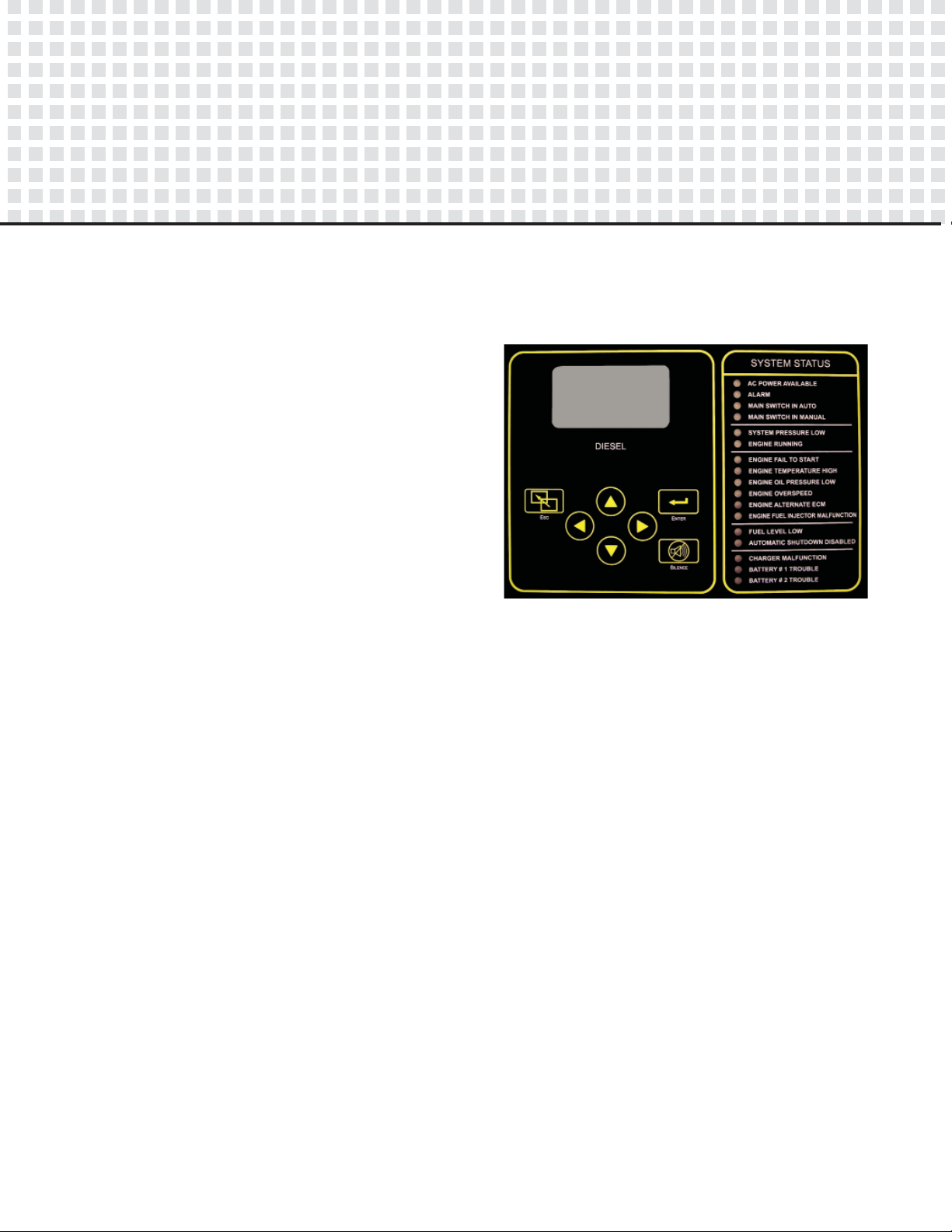
Door mounted display/interface panel featuring a 128 x 64 pixel backlit LCD Graphical Display,
Membrane Type User Control Push-buttons and
easy to read LED Indicators for:
• AC Power Available
• Alarm
• Main Switch In Auto
• Main Switch In Manual
• System Pressure Low
• Engine Running
• Engine Fail To Start
• Engine Temperature High
• Engine Oil Pressure Low
• Engine Overspeed
• Engine Alternate ECM
• Engine Fuel Injector Malfunction
• Fuel Level Low
• Automatic Shutdown Disabled
• Charger Malfunction
• Battery #1 Trouble
• Battery #2 Trouble
Additionally, the controller is constructed with
the following features specifi cally for the C1, D2
application:
• Top Mounted Enclosure Lifting Brackets
• Hermetically Sealed Pilot Devices and Relays
• SIS Type Wiring and Sleeve Type Wire Markers
• Stainless Steel Back Pan
• Door Stop Bracket (Holds door in open position)
• Enclosure Gland Plate
• ECD Drains (To drain accumulated condensate)
• External White Nameplates with Black Nomenclature
• 6” Base Mounting Legs
• Door Clamps and Padlock Hasp
Page 4

the batteries to insure they can accept a fast
charge. It also checks for missing or defective
batteries. If a missing or defective battery is
detected, a fault will be given.
Step 2 - Fast Charge Stage
Charges the batteries until they reach peak
voltage.
Step 3 - Bulk Charge Stage
Charges the batteries at a constant potential
of peak voltage until current reaches 500mA.
Step 4 - Float Charge Stage
Trickle charges the batteries to maintain peak
potential.
The battery chargers also feature the following:
• Selectable AC power voltage
• Selectable battery voltage
• Selectable battery type
• AC power fuse
• DC power fuse
• Charge cycle reset push-button
20 Amp Charging Circuit
When required, the controller can optionally
be supplied with a 20 Amp charging circuit. This is
accomplished by supplying 4 battery chargers in
parallel sets. The synchronization of the chargers is
accomplished by utilizing our unique Charger Link
module.
Optional 4-Charger, 20 Amp confi guration
Emerson Network Power - Global Headquarters
1050 Dearborn Drive
Columbus, OH 43085
Tel +1 614 888 0246
EmersonNetworkPower.com
While every precaution has been taken to ensure accuracy and completeness herein, ASCO assumes no responsibility, and disclaims all liability, for damages resulting from use
of this information or for any errors or omissions. Information and specifications are subject to change without notice.
Emerson, Consider It Solved., Emerson Network Power, the Emerson Network Power Logo, ASCO, Firetrol and the Firetrol Logo are trademarks or registered trademarks of
Emerson Electric Co. All other names and logos referred to are trade names, trademarks, or registered trademarks of their respective owners. ©2013 Emerson Electric Co.
CB1100H-50 (B)
ASCO Power Technologies - Firetrol Brand Products
111 Corning Road, Suite 120
Cary, NC 27518
Tel +1 1 460 5200 FaY +1 1 460 5250
Firetrol.com
 Loading...