


026-1400 Rev 3 22-MAR-2011
Facility Status Display (FSD)
Installation and Operation Manual


Retail Solutions
3240 Town Point Drive NW Suite 100
Kennesaw, GA 30144, USA
Phone: 770-425-2724
Fax: 770-425-9319
ALL RIGHTS RESERVED.
The information contained in this manual has been carefully checked and is believed to be accurate. However, Computer Process Controls, Inc. assumes no responsibility for any inaccuracies that may be contained herein. In no event will
Computer Process Controls, Inc. be liable for any direct, indirect, special, incidental, or consequential damages resulting
from any defect or omission in this manual, even if advised of the possibility of such damages. In the interest of continued
product development, Computer Process Controls, Inc. reserves the right to make improvements to this manual, and the
products described herein, at any time without notice or obligation.
CE/FCC COMPLIANCE NOTICE
Class A compliance for Facility Status Display under Part 15 of the FCC Rules and CE EN 55022. In a domestic environment this product may cause radio interference in which case the user may be required to take adequate measures.
READ ALL INSTRUCTIONS CAREFULLY
If the equipment is not used in the manner specified by the manufacturer, the protection provided
by the equipment may be impaired.


Table of Contents
1 INTRODUCTION.......................................................................................................................................................... 1
2 INSTALLATION ........................................................................................................................................................... 2
2.1. W
2.2. A
2.3. M
IRING ......................................................................................................................................................................... 2
LARM RELAYS............................................................................................................................................................ 3
OUNTING.................................................................................................................................................................... 3
3 SET UP FSD AND E2 COMMUNICATION .............................................................................................................. 5
3.1. STEP 1: A
3.2. STEP 2: S
3.3. STEP 3: S
DD FSD TO E2............................................................................................................................................. 5
ET UP IP ADDRESS FOR THE FSD ................................................................................................................ 5
ET THE E2 IP ADDRESS IN FSD ................................................................................................................... 6
4 ALARM OVERVIEW................................................................................................................................................... 7
4.1. A
LARM FILTERING........................................................................................................................................................ 7
4.1.1. Alarm Snoozing ..................................................................................................................................................... 7
5 FSD SCREEN NAVIGATION ..................................................................................................................................... 8
5.1. H
OME SCREEN ............................................................................................................................................................. 8
5.2. A
LARM LIST SCREEN ................................................................................................................................................... 8
5.2.1. Advisory Detail Screen ......................................................................................................................................... 9
5.3. D
ATA POINTS SCREEN ................................................................................................................................................. 9
5.3.1. Data Points Detail Screen .................................................................................................................................. 10
5.4. FSD C
ONFIGURATION SCREEN .................................................................................................................................. 11
5.4.1. Alarms Tab.......................................................................................................................................................... 11
5.4.1.1. Show RTN Alarms............................................................................................................................................................ 11
5.4.1.2. Show Reset Advisories ..................................................................................................................................................... 12
5.4.1.3. Display Asset/Alarm ......................................................................................................................................................... 12
5.4.1.4. Show Notices .................................................................................................................................................................... 12
5.4.1.5. Filter Advisories ............................................................................................................................................................... 12
5.4.1.6. Sort Data Points ................................................................................................................................................................ 12
5.4.1.7. Audible Alarm .................................................................................................................................................................. 12
5.4.1.8. Snooze Delay .................................................................................................................................................................... 13
5.4.1.9. Min Alarm Priority ........................................................................................................................................................... 13
5.4.2. Communications Tab ........................................................................................................................................ 13
5.4.2.1. E2 IP Address ................................................................................................................................................................... 13
5.4.2.2. E2 IP Port .......................................................................................................................................................................... 13
5.4.2.3. Display Number ................................................................................................................................................................ 13
5.4.3. General Tab ........................................................................................................................................................ 13
5.4.4. About Tab............................................................................................................................................................ 14
5.4.5. Backlight Time-out Setting.................................................................................................................................. 14
6 E2 DATA POINT SETUP FOR FSD ......................................................................................................................... 16
7 E2 ETHERNET PEER COMMUNICATIONS ........................................................................................................ 18
7.1. E
THERNET IP CONFIGURATIONS ................................................................................................................................ 18
7.2. H
ARDWARE SPECIFICATIONS...................................................................................................................................... 18
7.2.1. Components......................................................................................................................................................... 18
7.3. S
OFTWARE SPECIFICATIONS ....................................................................................................................................... 19
7.4. E
THERNET NETWORK LAYOUTS................................................................................................................................. 19
7.4.1. Closed Network Layout .................................................................................................................................... 19
7.4.2. Open Network Layout ...................................................................................................................................... 19
Table of Contents • v

7.5. SOFTWARE SETUP ....................................................................................................................................................... 20
7.6. T
ROUBLESHOOTING .................................................................................................................................................... 20
8 E2 ALARM ANNUNCIATOR SETUP...................................................................................................................... 21
9 SOFTWARE UPDATES ............................................................................................................................................. 21
10 SPECIFICATIONS.................................................................................................................................................... 22
vi • FSD Installation and Operation Manual 026-1400 Rev 3 22-MAR-2011

1 Introduction
One of the most important features of the E2 facility management system is to put vital system information at the fingertips of the service technician or store
manager. The FSD reports alarm information and
more, (such as temperatures, occupancy, case status,
and setpoints) and provides a centralized device for
store personnel to review information by communicating with the E2 via Ethernet connectivity (minimum E2 firmware revision 2.65F01).
can be installed virtually anywhere with a standard
Ethernet connection and 120V power source. Features include:
• 6” LCD touch screen (with backlight).
• Mounting plate for recessed installation.
• Audible alarm buzzer (with silence setting) and
red alarm LED (illuminates when there is an active advisory).
• Auxiliary relay provides a dry contact closure
that follows the alarm relay output.
• Connectivity with E2 via TCP/IP Ethernet.
• Remote software upgrading of the FSD.
• Display of up to 200 alarms.
• Display of up to 150 customizable data points.
Figure 1-1 - Facility Status Display
The FSD has a touch screen color display for quick
navigation and can be mounted in a separate, remote
location from the E2 controller, which enables alarms
and other relevant store information to be viewed
from where it is most convenient for the user.
The FSD can be configured to filter out notices
and/or return-to-normal alarms, and provides a quick
review of all advisories and detailed advisory information. The FSD also receives alerts and provides annunciated alarms and alarm information directly to
store and department managers. This compact unit
Introduction • 1
2 Installation
Inside Back of Enclosure
9.0”
STEP 3
8.0”
Transformer
G
r
o
u
n
d
1
2
0
V
A
C
N
e
u
t
r
a
l
2
0
8
V
A
C
2
4
0
V
A
C
Hot in
FSD Circuit
Board
RS2
32
AUX
++_
+
__
E
a
r
t
h
G
r
o
u
n
d
A
l
a
r
m
L
E
D
H
o
r
n
V
d
e
O
u
t
D
i
s
p
l
a
y
STEP 1
This section of the manual covers wiring and
mounting for the FSD.
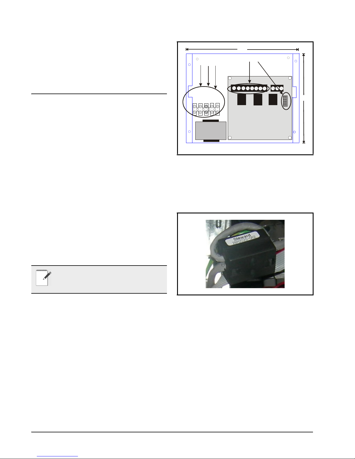
2.1. Wiring
1. Step 1: Using the four screws on the front of
the mounting plate, unscrew the cover of the
FSD and remove, exposing the back of the
enclosure. Once the top has been separated
from the back of the enclosure, unplug the 8pin connector and RS232 cable (Step 1 of
Figure 2-1) from the circuit board (P/N 537-
1100).
2. Step 2: Mount the base enclosure and refer to
Section 2.3., Mounting for instructions.
3. Step 3: Once the unit has been mounted,
depending on the voltage input, wire either
120VAC, 208VAC, or 240VAC Hot leg to
the corresponding terminal block label. Then
wire the Neutral or L2 leg to the terminal
block labeled Neutral. Wire Ground to
Ground as indicated by Step 3 of Figure 2-1.
Figure 2-1 - 8-Pin Connector and RS232 Cable Connections
4. Step 4: Open the ferrite (P/N 090-0008) and
run the Ethernet cable through, wrapping the
cable around the ferrite twice (two turns),
near the Ethernet port (LAN) on the back of
the display, and close the ferrite (Figure 2-2)
around the Ethernet cable.
NOTE: Provide either 120VAC, 208VAC, or
240VAC (40VA max) to the FSD terminal
block through a store circuit breaker. The
breaker size should be 20 amps or less.
Figure 2-2 - Ferrite Installation on Ethernet Cable
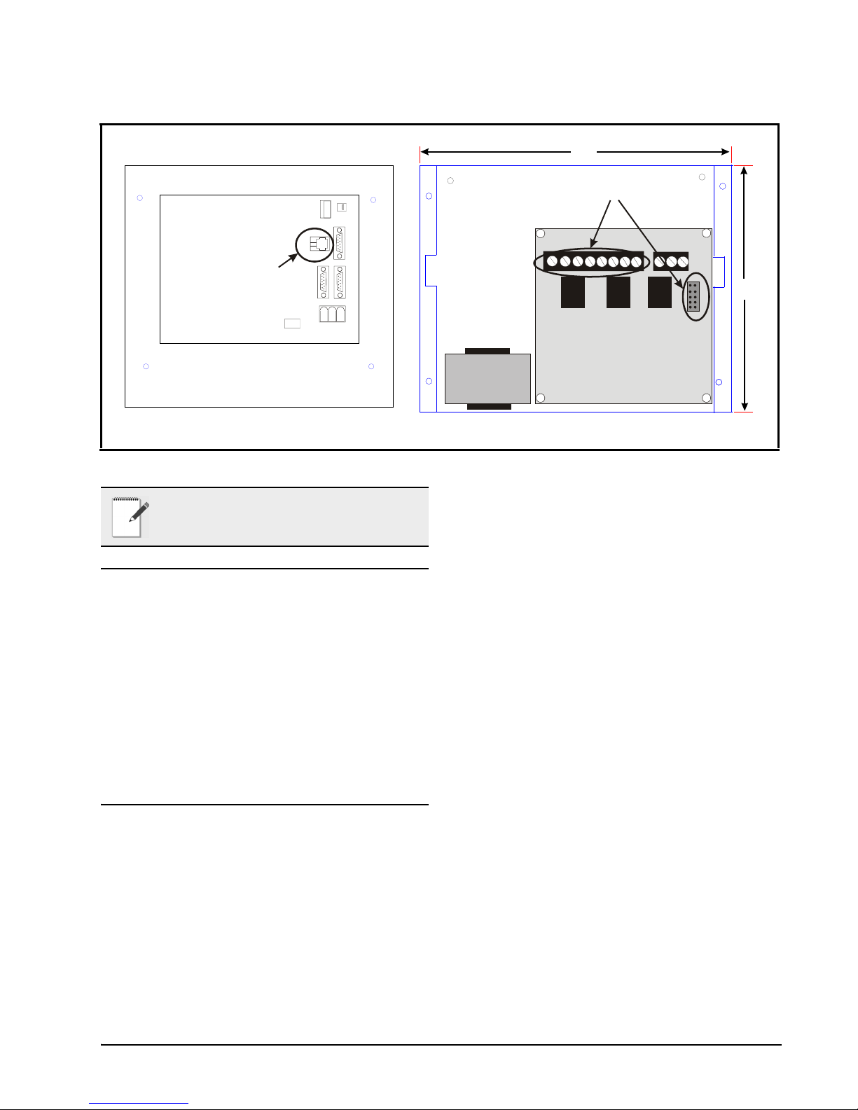
5. Step 5: Plug the Ethernet cable into the RJ45
connector (LAN) on the back of the FSD’s
display module (P/N 750-5100) as indicated
by Step 5 of Figure 2-3.
6. Step 6: Reconnect the 8-pin connector and
RS232 cable to the circuit board in
Step 6 of Figure 2-3.
7. Step 7: Replace the mounting plate back onto
the enclosure and attach using the four
screws.
2 • FSD Installation and Operation Manual 026-1400 Rev 3 22-MAR-2011
Inside Back of Enclosure
9.0”
8.0”
Transformer
Back of FSD Panel
L
A
N
C
O
M
1
C
O
M
2
C
O
M
3
G
N
D
-
v
d
c
+
v
d
c
FSD Circuit
Board
RS2
3
2
A
U
X
+
+_+__
E
a
r
t
h
G
r
o
u
n
d
A
l
a
r
m
L
E
D
H
o
r
n
V
d
e
O
u
t
D
i
s
p
l
a
y
STEP 5
STEP 6
O
N
/
O
F
F
S
w
i
t
c
h
Figure 2-3 - Wiring Layout of FSD Enclosure
NOTE: Do not exceed the maximum Ethernet
cable length of 328 feet (100 meters).
2.2. Alarm Relays
• An audible alarm will sound when a new advisory has been received.
• The red alarm LED on the front of the display
module illuminates any time there is an active
advisory.
• The auxiliary relay (dry contact closure) will
activate any time there is an active advisory.
This output allows an external alarm indicator
to be installed away from the board.
2.3. Mounting
The FSD is recess-mounted into a wall or other
mounting surface. The face plate with the LCD display (front portion of the unit) will mount flush
against the surface around the outside of the opening
once the power supply box has been mounted inside
the wall.
1. Cut a rectangular hole into the mounting surface 8.0” high by 9.0” wide, by at least
3.875” deep (20.32 cm high by 22.86 cm
wide by at least 9.84 cm deep). When cutting
the mounting hole, allow at least 1/2” (1.27
cm) clearance around the hole for face plate
mounting (Figure 2-5).
2. Once this hole is cut, mount the unit as
desired (Figure 2-4), and position the enclosure so that the four support tabs are flush
against the outside lip of the opening in the
wall.
3. Use a screwdriver to bend the four push-out
tabs (two on each side) against the inside of
the drywall so that they hold the power supply box in place.
Alarm Relays Installation • 3

Figure 2-4 - Mounting The Power Supply Box
Open Side of
Power Supply Box
Mount Back Portion of FSD Power Supply Box
Inside Wall
9.0”
8.0”
Support
Tabs (4)
3
.
8
7
5
”
Push-out
Tabs
Conduit
Knock-outs
Drawing Not To Scale
Face Plate
Screw Holes (4)
Open Side of
Power Supply Box
9.0”
8.0”
1/2”
1/2”
leave ½” clearance
each side for face plate
1/2”
1/2”
Figure 2-5 - Leave 1/2” For Face Plate Mounting
4 • FSD Installation and Operation Manual 026-1400 Rev 3 22-MAR-2011

3 Set Up FSD and E2
Communication
Because the FSD device retrieves all software information from the E2 controller, communication
must be established between the FSD and the E2 at
start-up. To start, add the FSD application to the E2.
3.1. STEP 1: Add FSD to E2
1. Log into the E2 controller and press the
Menu button.
F2: NEXT TAB to go to the ECT
tab, cursor down to Status Display,
and then enter the desired number of
devices (Figure 3-2).
2. Press
3. Press
4. Press
5. Enter the desired number of Status Display
(System Configuration)
(Network Setup)
(Connected I/O Boards & Control-
lers).
devices.
• If using an E2 controller with firmware version 2.80 or below, cursor
down to ECT Devices section and
then add the desired number of Sta-
tus Display devices (Figure 3-1).
Figure 3-2 - Connected I/O Screen Setup (E2 firmware versions
2.81 and above)
3.2. STEP 2: Set Up IP
Address for the FSD
DHCP is enabled by default. If you have a DHCP
server, the FSD will retrieve an IP Address automatically. If you wish to set up a static IP Address, follow
these steps:
1. Touch the tool icon and enter the passcode on the security screen (default code is
400) as shown in Figure 5-10.
2. Select the General tab and the Exit
Application button.
3. A loader screen will appear. Touch Exit
Loader at the top right of the screen.
Figure 3-1 - Connected I/O Screen (E2 firmware versions 2.80
and below)
• If using an E2 controller with firmware version 2.81 or above, press the
STEP 1: Add FSD to E2 Set Up FSD and E2 Communication • 5
4. The desktop screen will appear. Select Start
> Settings > Network and Dial-up
Connections.
5. Double-click the icon labeled SMSC91181.
6. From the IP Address tab, (Figure 3-3)
choose Specify an IP address. (If using a
Hostname for E2 instead of an IP Address,
contact your IT administrator and continue

from Step 9.)
Figure 3-3 - IP Address Tab
7. Toggle the virtual keyboard by touching the
keyboard/pen icon on the lower right to
toggle the virtual keyboard:
8. Enter the IP Address, Subnet Mask, and
Default Gateway as specified by your IT
administrator.
9. Click OK to save; close the next window.
10. Once at the desktop screen, click the reboot
code is 400) into the blank field on the first
boot loader screen (Figure 3-5) and touch
Configure. (Touching the inside of this field
will toggle the virtual keyboard.)
Figure 3-5 - First Boot Loader/Startup Screen
2. On the second boot loader screen,
(Figure 3-6) enter the IP Address or Hostname of the E2 that the FSD will be communicating with. (If using a Hostname for E2
instead of an IP Address, contact your IT
administrator for the Hostname.)
icon at the bottom of the screen. Click
OK on the Do you want to reboot? window:
Figure 3-4 - Click OK
3.3. STEP 3: Set the E2 IP
Address in FSD
To set up the FSD, the E2’s IP address or Hostname that the FSD will communicate with must be entered.
When the FSD is powered up for the first time, the
Start-up or Boot Loader screens will appear.
1. Log on by entering the passcode (default
Figure 3-6 - Second Boot Loader/Startup Screen
3. Touch Apply.
4. Reboot the unit by cycling power.
6 • FSD Installation and Operation Manual 026-1400 Rev 3 22-MAR-2011

4 Alarm Overview
The FSD contains an audible alarm that can be enabled or disabled by the installer or service technician
and is pass-code protected. See Section 5.4.1., Alarms
Tab for alarm parameter configuration details.
The audible alarm will annunciate any time there
is an active alarm displayed on the alarm. If alarming
or Snoozing is active and the filtered alarm list indicates that no alarm is active, any active state (alarm or
Snooze) will be canceled automatically.
Automatic color-coding allows for simple differentiation between those advisories that are urgent and
those that have already been resolved.
The FSD retrieves an alarm list from the controller
approximately every 20 seconds, depending on your
connection speed and other factors. The FSD will receive the alarm list from a single E2 or multiple E2s
if one is configured as the alarm annunciator (Section
8, E2 Alarm Annunciator Setup).
If a new alarm is detected while in snooze delay,
the snooze will be cancelled and the audible alarm
will be activated.
4.1. Alarm Filtering
Alarms can be filtered by:
• Setting the minimum alarm priority - specifies
a minimum priority for alarms to be filtered.
Alarms with a priority greater than the Minimum Alarm Priority will not be shown. Alarms
with a priority equal to or lower than this value
will be shown.
• Return to Normal flag
• Show Notices flag
TEXT
COLOR
Red Active advisory and/or failure
Yellow Active Notice
Green Return-To-Normal Advisories
Blue Acknowledged Alarms, Reset
alarms
Table 4-1 - Advisory Text Color Key
ADVISORY STATE
4.1.1. Alarm Snoozing
The Snooze Alarm allows the user to silence the
audible alarm for a configurable amount of time. If
the alarm is still active after the Snooze Delay, or if
another advisory is generated, the audible alarm will
re-activate. The maximum snooze time is 4 hours.
Snooze Delay and disable settings are part of passcode protected setup under Configuration Setup in the
FSD. When an alarm is in snooze, the Home screen
(see Figure 5-1) will indicate the remaining snooze
time.
Alarm parameters can also be set up in the E2 under General setup of the Facility Status Display application (Figure 6-1).
If an alarm is found active in the filtered list, the
FSD will:
• Indicate the alarm by asserting a visual indication (the blinking word alarm and sounding a
horn if internal/external horn is enabled).
• Enable the Snooze Alarm. If Snooze is active,
the remaining snooze time will be displayed in
place of the Snooze Alarm button.
The alarm light remains illuminated as long as any
advisory is active (independent of audible alarm) with
visible countdown timer (if Snooze is enabled) until
audible alarms is reactivated.
Alarm Filtering Alarm Overview • 7
An audible alarm is activated any time an advisory
is active (in Alarm or Fail State). Snoozing does not
change the state of advisories in E2.
Once an audible alarm has annunciated, the alarm
may be “snoozed” by touching Snooze Alarm on the
Home screen. The audible alarm can be disabled
through the E2 or the FSD alarm configuration screen
(see Figure 5-11) under the Audible Alarm setting.
NOTE: If communications are lost between the
E2 and the FSD, an alarm will generate. The
delay for the alarm will be consistent with the
offline delays used in the E2 for board offline
alarming.

5 FSD Screen
Navigation
The FSD provides users with real-time alarm and
system information that is read-only.
ICON ACTION
Displays the Home screen of the FSD
and the most active advisory in the
alarm list.
Displays list of multiple advisories in
the alarm log and places a selected advisory on the Home screen.
Displays expanded details of a selected advisory (including any advisory on
the Home screen) or a data point on the
Status screen.
Toggles display of data point information based on data points that have
been set up in the E2.
Opens security screen to access FSD
configuration settings.
UP arrow scrolls upward through
items on each screen and through multiple alarms on the Home screen.
DOWN arrow scrolls downward
through items on each screen and
through multiple alarms on the Home
screen.
Table 5-1 - Icon Descriptions
5.1. Home Screen
The Home screen is the single alarm screen or
main screen. The FSD displays this screen when first
powered up and displays the first (most recent) alarm
entry screen. The Home screen is also displayed when
the user touches the Home icon from any screen.
Figure 5-1 - Home or Main Screen
Touching the Home icon from any screen will take
you to the most recent alarm in the list. The Home
screen displays basic information about an E2 alarm
along with information such as the FSD name, current
time and date. The Home screen also displays whether the FSD is communicating with the E2 or if communication with the E2 has been interrupted or
stopped.
If no alarms are being generated, the Home screen
will display “No Alarms - System Normal” message
in green.
If alarms have been generated, the UP arrow will
scroll up to the previous alarm. Touching the DOWN
arrow will scroll down to the next alarm in the list.
8 • FSD Installation and Operation Manual 026-1400 Rev 3 22-MAR-2011
5.2. Alarm List Screen
The Alarm List screen shows all filtered alarms in
a list called the alarm log. Multiple alarm entries are
shown with a scroll bar to navigate through the alarm
list. UP and DOWN arrows will page up and page
down on this screen.

Figure 5-2 - Alarm List Screen
Title Data Point
Data Points Screen Name
If the alarm list is empty, “System Normal - No
Alarms” is displayed.
To see a detailed status of an advisory, select the
advisory in the list and touch the magnifying glass
(details icon) and the Advisory Detail screen for
exceeded) the configured priority of the advisory, Return-To-Normal information, and if available, the
limit that was exceeded.
5.3. Data Points Screen
The Data Points screen is a view-only screen that
shows the list of all data points being monitored by
the FSD.
that advisory will open. Touch the bell (advisory)
icon again to place that advisory on the Home screen.
5.2.1. Advisory Detail Screen
Advisory Details shows expanded information
about the selected advisory:
Figure 5-3 - Advisory Detail Screen
• Current alarm number with the total number of
alarms in the alarm list
• Alarm summary for single alarm
Time stamp, alarm ID string, associated property,
data point information, current status, why the alarm
was triggered (for example, if a case temp limit was
Figure 5-4 - Data Points Screen
In Figure 5-4, the Data Points screen name is dis-
played across the top of the screen (in this example, it
is called Department Status). This name is configured under the Status Title parameter under FSD
General Setup in the E2 controller (Figure 6-1).
The Title Data Point string name and pointer display to the right of the Data Points screen name. In
Figure 5-4, Season is the Title Data Point string name
followed by the pointer value, WINT. The Title Data
Point string and pointer can be configured also in the
FSD General Setup tab in the E2 controller
(Figure 6-1).
See Section 6, E2 Data Point Setup for FSD to
configure these parameters for the FSD Data Point
screen.
Data Points Screen FSD Screen Navigation • 9

5.3.1. Data Points Detail Screen
When a data point is selected on the Data Points
screen (Figure 5-4) and the details icon is
touched, all details about the pointer will be displayed
such as notice, alarm (Figure 5-6), and override
(Figure 5-7) status information when these values are
active:
Figure 5-7 - Detailed Information if Data Point is in Override
If no data point is selected when the details icon is
touched, a reminder will appear:
Figure 5-5 - Detailed Data Point Information
Figure 5-6 - Detailed Information if the Data Point Failed
Figure 5-8 - Select A Data Point Reminder Screen
If a pointer has not been defined in the E2 applica-
tion, a three-dash result will appear. If this three-dash
(- - -) value is selected and the details icon is
touched, the following message will appear:
10 • FSD Installation and Operation Manual 026-1400 Rev 3 22-MAR-2011
Figure 5-9 - No Pointer Is Defined Message

5.4.1. Alarms Tab
5.4. FSD Configuration
Screen
The Configuration screen has four tabs that are
used to configure the FSD. When the tool icon is
touched, the security login screen appears:
Figure 5-10 - Security Screen Login - Enter Passcode
Configure alarm information on the Alarms tab
with the following parameters:
• Show RTN Alarms
• Show Reset Advisories
• Display Asset/Alarm
• Show Notices
• Filter Advisories
• Sort Data Points
• Audible Alarm settings
• Set snooze delay in minutes
• Set minimum alarm priority
Enter the passcode (the default code is 400 and can
be configured in the E2 under Facility Status Display
General Setup under the Pass Code parameter
(Figure 6-1) and touch Enter to open the first Configuration screen (Figure 5-11).
• Cancel exits the log in screen and returns you
to the Home screen.
• Clear erases the numbers entered in the login
field and allows you to re-enter the passcode.
The FSD Configuration has four configuration
tabs located across the top with three command keys
that appear along the bottom of each configuration
screen. Touch Toggle Keyboard to open an onscreen “qwerty” style keypad for configuring parameters. Touch OK to save and exit to the Home screen,
Cancel to discard changes and exit to the Home
screen.
Figure 5-11 - Alarm Configuration
These alarm parameters can also be set up in the
E2 under General setup of the Facility Status Display
application (Figure 6-1).
5.4.1.1. Show RTN Alarms
This alarm setting determines visibility of an
alarm on the FSD that has been returned to normal
(RTN). For example, if a case goes into alarm, the
FSD will see the alarm; however, if the alarm returns
to normal, the alarm will not be visible on the FSD, although it is seen in the individual controller’s alarm
log as Return-To-Normal. Enable the checkbox to
show returned-to-normal alarms, uncheck to filter
out.
FSD Configuration Screen FSD Screen Navigation • 11

5.4.1.2. Show Reset Advisories
This alarm setting enables you to display or hide
reset alarms on the FSD. Reset alarms are alarms that
have been forced to normal condition or “Reset-toNormal.” Enable the checkbox to show reset alarms
or uncheck to filter out.
5.4.1.3. Display Asset/Alarm
This setting determines how advisory information
will display on the FSD main alarm screen (whether
alarm is displayed over asset or vice versa). Alarm describes the type of alarm that was generated, while as-
set details the source where the alarm occurred.
If the Display Asset/Alarm checkbox is unchecked, the main alarm screen will display advisory
information in the normal order, that is, alarm over
asset. In Figure 5-12, the alarm name (“Failed Sensor
or Bad Wiring”) is displayed over the asset detail
(“E3.1 >> EC2 391 CC_001 >> TERM TEMP”).
If the checkbox is enabled, alarm information will
display in the reverse order (i.e., asset over alarm).
Refer to Figure 5-13 for a sample illustration.
Figure 5-13 - Reversed Setting -Asset over Alarm
5.4.1.4. Show Notices
This notice setting determines whether the FSD
will display notices along with other types of advisories, or whether these notices will be filtered out of the
FSD. Enable this box to show Notices in the alarm
list, uncheck to filter out.
Figure 5-12 - Normal Setting - Alarm over Asset
5.4.1.5. Filter Advisories
This setting causes the FSD to display only advisory information of points that are included in the
monitored data point list. Advisories that are outside
the monitored data point list will be excluded from the
display list. Enable the checkbox to filter advisories,
or uncheck to filter out.
5.4.1.6. Sort Data Points
If this setting is enabled, it will cause points with
active advisory to display on top of the list of monitored data points on the FSD.
5.4.1.7. Audible Alarm
Audible Alarm will be active any time there is an
active alarm or a fail advisory displayed. The Audible
Alarm drop-down list allows you to configure the audible alarm buzzer on the FSD with three settings: Ex-
ternal, Internal, and None.
• External is the default. This setting enables the
audible external horn connected to the relay
board as the alarm indicator.
12 • FSD Installation and Operation Manual 026-1400 Rev 3 22-MAR-2011
• Internal enables the touch-screen beep as the

alarm indicator.
5.4.2.2. E2 IP Port
• None disables all audible alarm indicators.
5.4.1.8. Snooze Delay
Snooze Delay sets the number of minutes to silence the audible alarm buzzer when the snooze button on the FSD is touched.
5.4.1.9. Min Alarm Priority
This alarm priority setting specifies a minimum
priority for alarms to be filtered. Alarms with a priority greater than the Minimum Alarm Priority will not
be shown. Alarms with a priority equal to or lower
than this value will be shown.
(1 to 99 range: 1=highest, 99=lowest)
5.4.2. Communications Tab
The E2 IP Port is the port number used by the FSD
to connect with the E2 unit. The port number in this
field must match the FSD Client Port field in the E2
for the FSD and the E2 to communicate. The default
port is 14106.
Press Alt + T on the E2 to locate the FSD Client
Port field. If a different port is desired, enter that port
number in this field.
5.4.2.3. Display Number
The display number is the FSD device number in
the E2. This number is the FSD’s unique address and
the application to which it corresponds.
5.4.3. General Tab
Under General configuration the FSD name is
shown with Reboot Unit and Exit Application options. Touch Reboot Unit to restart the FSD. Exit
Application will exit this General configuration
screen and go to the Boot Loader or Start up screen.
Figure 5-14 - Communications Screen - Set E2 Parameters
5.4.2.1. E2 IP Address
Enter the IP address or Hostname of the E2 from
which the FSD will be receiving alarms. Note that if
more than one
be set up as the alarm annunciator for that site. (See
Section 6, E2 Data Point Setup for FSD.) The FSD
will receive alarms from that alarm-annunciator E2
for the entire site. The FSD will point only to a single
E2 at a site (it will not poll multiple controllers for
alarms).
For multiple E2s at a site, enter the IP address of
the alarm-annunciator E2. If one E2 is located at a
site, enter the IP address for that single E2.
FSD Configuration Screen FSD Screen Navigation • 13
E2 controller is at a site, one E2 must
Figure 5-15 - General FSD Information Screen

5.4.4. About Tab
Read-only, general information about the FSD is
displayed on this screen including copyright and revision information. Touch OK or Cancel to exit the
About screen and return to the Home screen.
Figure 5-16 - FSD About Tab
5.4.5. Backlight Time-out Setting
screen.
Figure 5-18 - General FSD Information Screen
4. The desktop screen will appear
(Figure 5-19). Press and hold on the desktop
screen to bring up the pop-up desktop menu
and select Properties.
To increase the life of the display, the FSD’s backlight time-out setting is pre-configured to turn off the
backlight automatically if the device is idle for more
than 10 minutes. To change the backlight setting:
1. Touch the tool icon and enter the passcode on the security screen as shown in Fig-
ure 5-10.
2. Select the General tab and touch the Exit
Application button (Figure 5-17).
Figure 5-19 - Desktop Screen
Figure 5-17 - General FSD Information Screen
3. A loader screen will appear (Figure 5-18).
Touch Exit Loader at the top right of the
14 • FSD Installation and Operation Manual 026-1400 Rev 3 22-MAR-2011

The Display Properties window (Figure 5-20)
opens:
Figure 5-20 - Display Properties Window - Backlight Settings
5. Select the Backlight tab to configure the
Automatically turn off backlight while on
external power setting, and from the drop-
down list, choose when the backlight will
automatically turn off.
6. To save your settings, touch and drag the
Display Properties window to the left until
you see OK in the upper right corner. Touch
OK to save and return to the desktop screen.
FSD Configuration Screen FSD Screen Navigation • 15

6 E2 Data Point
Setup for FSD
Set up data points that will be monitored.
1. Log into the E2 controller.
2. Go to the Facility Status Display application
setup (Menu, 5, #107 on the Configured
Applications menu).
3. Press F5 Setup and enter the number of data
points to be set up in the Num Data Points
field (a maximum of 150 data points can be
entered).
the FSD Data Point screen (Figure 5-4).
The number of data points entered will automatically update under Data Points (Data Pts) and Point
Names (Pts Names) setup.
Figure 6-1 - Enter the Number of Data Points to Set Up
4. In the Status Title field, enter the name you
wish to appear as the Data Points screen
name on the FSD Data Points screen (Figure
5-4).
5. Enter the pointer and string values for the
Title Data Point in the Title Data Pt and
Title Data Str fields, respectively. This will
change the default Title Data Point details on
Figure 6-2 - Enter the Title Data Point Pointer and String Values
If the Title Data Point parameters are not changed,
the FSD Data Points screen will use the default values
set for these parameters (i.e., the Global Data’s OAT).
6. Press F2 Next Tab to go the Data Pts setup
and enter the desired data points to be monitored by pressing F4: Look Up.
Data Points are entered in Controller:Applica-
tion:Property format (see Figure 6-3 for an exam-
ple).
7. Using F4: Look Up, choose the name of the
controller for Controller: (THIS.03.1), the
name of the application for Application:
(STANDARD CKT01), and which input or
output of that application you wish to moni-
16 • FSD Installation and Operation Manual 026-1400 Rev 3 22-MAR-2011

tor for Property:(CONTROL TEMP).
Figure 6-3 - Example of Data Point(s) Setup in E2
A point name is the unique name given to the data
point (specified by the user) and will be displayed on
the FSD screen.
When setting up data points for multiple E2s at a
site, note that F4: Lookup will not allow you to select
data points from another (remote) E2 unless you are
running E2 firmware revision 2.69F01 or higher.
For E2 firmware prior to revision 2.69F01, data
points can be selected from a remote E2 by connecting the data points to Global Data.
Ethernet peer communications is required for boxto-box hookup. For more information, refer to Sec-
tion 7, E2 Ethernet Peer Communications.
NOTE: Colons “:” cannot be used in the text
you enter when naming the data point, as colons are already used to separate each value.
NOTE: If a pointer is undefined in the E2
application, it will display as three dashes
(- - -) on the Facility Status Display screen.
8. Go to the Pts Names tab and enter a name
for the data point (Figure 6-4).
Figure 6-4 - Entering a Data Point Name
9. After entering the data point, enter a
unique name in the Data Name field on
this screen. If no name is assigned, the
data point will be displayed in the default
Controller:Application:Property format.
FSD Configuration Screen E2 Data Point Setup for FSD • 17

7 E2 Ethernet Peer
Communications
Communication between E2 controller version
2.10 or greater may now be implemented through an
Ethernet network using TCP/IP protocol. To utilize
peer connections over Ethernet, the following tasks
must be performed:
• Upgrade the E2 controller firmware to version
2.10 or greater.
• Install an industry-standard Ethernet switch(es)
or hub(s) in an area or areas nearby the E2 controllers.
• Install Ethernet straight-through cabling at the
site from each E2 to the switch or hub. Installation of RJ-45 connectors may be necessary to
achieve this goal. The recommended cabling is
CAT 5.
(straight-through cable).
• 328 feet (100 meters) is the maximum distance
allowed between devices before a switch or hub
must be added.
7.2.1. Components
Equipment
Type
Ethernet Five- or
Nine-port Switch
(may require an
additional power
supply)
* Industrial grade
* Operating/storage temp range:
* Vibration: IEC68-2-6
* RH: 5 to 95%
* UL 508A, CE approved
* Supports 10Base-T crossover
* Supports all IEEE 802.3 protocol
* Supports Auto Crossover MDI/
* Screw-terminal power connec-
Specifications
-40°F to 185°F
cable
MDI-X
tors
7.1. Ethernet IP
Configurations
If using an open network configuration (see Sec-
tion 7.4.2., Open Network Layout), contact your IT
Network Administrator for all IP configuration information (IP Address, Subnet Mask, Primary and Default Gateway settings).
7.2. Hardware
Specifications
Standard industry-accepted practices for wiring of
Ethernet networks are expected. E2 controllers use a
star topology, identical to PC deployment. This includes a unique “point-to-point” run from a switch or
hub to the controller (see Table 7-1 for hub part numbers for ordering). This is done with Category5 (or
better) cable. Maximum distance for a run of 10BaseT
is 328 feet (100 meters) (11.5 dB loss max).
Ethernet Surge
and Lightning
Protector
(recommended)
10-Base-T/100Base-TX Hub
10-Base-T/100Base-TX Hub
Table 7-1 - Equipment for E2 Ethernet Peer Communications
NOTE: An external power supply may be
needed.
* Industrial grade
* Surge capacity: 1 kA / line
*Operating temp range: -40°F to
185°F
*Max frequency: 155 MHz
*Clamp and rated: 10V and 5V
Room Temperature
(0 to 50 C)
P/N 570-0100
Extended Temperature
(-40 to 65 C) P/N 570-0200
• The maximum number of controllers allowed
on an IP subnet is 20. All E2 controllers that
must communicate with each other must be on
the same subnet.
• Recommended Ethernet cabling is CAT 5
18 • FSD Installation and Operation Manual 026-1400 Rev 3 22-MAR-2011

7.3. Software
Specifications
TCP/IP
E2 controller versions 2.10 and later communicate
between controllers using the TCP/IP protocol. TCP
Port 7238 is the default for connections established
between the controllers. All peer communications occur over this port.
7.4. Ethernet Network
Layouts
The two types of network options for E2 controllers using Ethernet communications are:
1. “Closed Network” - E2 devices are not con-
nected to a store’s LAN. (The only devices
on the network are the E2 controllers themselves.) This network type is used if there is
no need to integrate the network into the
company’s intranet.
2. “Open Network” - E2 devices are connected
to the store’s LAN. (Devices on the network
include E2s and other Ethernet-TCP/IP
devices.) This network type is used if the
network will be connected to the store’s
LAN.
NOTE: The gateway E2 is the E2 controller at
a remote site to which UltraSite directly connects. It is through this E2 that UltraSite com-
municates with the other controllers (defined
as the “non-gateway” E2s and external entities such as
UltraSite, InSite, Site Manager, etc.).
7.4.1. Closed Network Layout
Figure 7-1 - Closed Network Layout
7.4.2. Open Network Layout
NOTE: Contact your IT Network Administrator for setup parameters for both closed
and open networks.
The E2 peer Ethernet network facilitates communications between E2 controllers. These include at
least the following:
• Routing of messages between external entities
such as UltraSite, InSite, Site Manager, and
non-gateway E2 controllers.
• Distribution of global data and other network
variables such as system time, controller identification, etc.
• Communication between E2 controller applications such as Remote Login and Remote File
Services.
Software Specifications E2 Ethernet Peer Communications • 19
Figure 7-2 - Open Network Layout

7.5. Software Setup
1. Log on to the E2 controller
2. Navigate to the TCP/IP setup screen
(Alt + T).
4. Change Network Type to: Ethernet (ETH)
and press Enter. The Group Name field is
now visible.
NOTE: If unsure of any tab settings, it is recommended that the default settings be used.
NOTE: DHCP does not have to be enabled if
you have the IP Address, Subnet Mask, and
Primary Gateway settings. (Contact your IT
Network Administrator for all IP configuration
information.) If you do not have the IP configuration
settings, and there is a DHCP server on the network, set
DHCP Enabled to Yes and it will retrieve the information from the server and populate those fields. E2 controllers must all have the same Ethernet Subnet in order
to communicate box-to-box.
5. Once the Ethernet network type is enabled,
enter a unique site name in the Group Name
field.
NOTE: The site name is the unique identifier
for the site that will allow the controllers within
the same group to share data.
Figure 7-3 - TCPIP Setup Screen
3. Tab over to the Peer Netwrk tab:
Figure 7-5 - Peer Network Tab - Set Group Name
All controllers that you would like to appear in this
group must all have the same group name and must be
using the same network type.
7.6. Troubleshooting
Network troubleshooting is outside the scope of
this section (Section 7, E2 Ethernet Peer Communi-
cations). Consult your IT Network Administrator for
any additional information needed.
Figure 7-4 - Peer Network Tab - Set Network Type
20 • FSD Installation and Operation Manual 026-1400 Rev 3 22-MAR-2011

8E2 Alarm
9Software
Annunciator
Setup
If more than one E2 is at a site, set up one E2 as the
alarm annunciator. The FSD will receive alarms from
that alarm-annunciator E2 for the entire site.
Any E2 on the network that has a modem or Ethernet connection can be set up as an alarm annunciator,
but only one alarm annunciator per network is allowed. To set up from the Main Menu:
1. Press
2. Press
3. Press
4. Set Alarm Annunc field to Ye s .
(System Configuration)
(System Information)
(General Controller Info)
Updates
Updates to FSD application functionality will automatically be synched with the update of E2’s firmware. Any software the device runs will be retrieved
from the configured E2.
Figure 8-1 - Alarm Annunciator Setup
NOTE: When the E2 is set up as an Alarm Annunciator, the Home screen on the E2 becomes
the Alarm Log.
Troubleshooting E2 Alarm Annunciator Setup • 21

10 Specifications
Voltage Input 120VAC, 208VAC, or 240VAC +10%, -15%
Transformer Output
to Circuit Board
Maximum Current 1.0 amp
Humidity 10 to 95% @ 104°F (40°C) (relative humidity, non-condensing)
Operating Temp 32 to 122°F (0 to 50°C)
Storage Temp -4 to 140°F (-20 to 60°C)
Dimensions Screen (diagonal): 3.5” / Flush mounting plate: 9” x 10” / Mounting hole: 9” x 8”
Table 10-1 - Facility Status Display Specifications
24VAC
22 • FSD Installation and Operation Manual 026-1400 Rev 3 22-MAR-2011
 Loading...